WO2017204010A1 - シートベルト装置 - Google Patents
シートベルト装置 Download PDFInfo
- Publication number
- WO2017204010A1 WO2017204010A1 PCT/JP2017/018152 JP2017018152W WO2017204010A1 WO 2017204010 A1 WO2017204010 A1 WO 2017204010A1 JP 2017018152 W JP2017018152 W JP 2017018152W WO 2017204010 A1 WO2017204010 A1 WO 2017204010A1
- Authority
- WO
- WIPO (PCT)
- Prior art keywords
- seat belt
- belt
- pretensioner
- lap
- retractor
- Prior art date
- Legal status (The legal status is an assumption and is not a legal conclusion. Google has not performed a legal analysis and makes no representation as to the accuracy of the status listed.)
- Ceased
Links
Images


Classifications
-
- B—PERFORMING OPERATIONS; TRANSPORTING
- B60—VEHICLES IN GENERAL
- B60R—VEHICLES, VEHICLE FITTINGS, OR VEHICLE PARTS, NOT OTHERWISE PROVIDED FOR
- B60R22/00—Safety belts or body harnesses in vehicles
- B60R22/18—Anchoring devices
- B60R22/195—Anchoring devices with means to tension the belt in an emergency, e.g. means of the through-anchor or splitted reel type
-
- B—PERFORMING OPERATIONS; TRANSPORTING
- B60—VEHICLES IN GENERAL
- B60R—VEHICLES, VEHICLE FITTINGS, OR VEHICLE PARTS, NOT OTHERWISE PROVIDED FOR
- B60R22/00—Safety belts or body harnesses in vehicles
- B60R22/28—Safety belts or body harnesses in vehicles incorporating energy-absorbing devices
-
- B—PERFORMING OPERATIONS; TRANSPORTING
- B60—VEHICLES IN GENERAL
- B60R—VEHICLES, VEHICLE FITTINGS, OR VEHICLE PARTS, NOT OTHERWISE PROVIDED FOR
- B60R22/00—Safety belts or body harnesses in vehicles
- B60R22/34—Belt retractors, e.g. reels
- B60R22/36—Belt retractors, e.g. reels self-locking in an emergency
- B60R22/38—Belt retractors, e.g. reels self-locking in an emergency responsive only to belt movement
Definitions
- the present invention relates to a seat belt device provided with a pretensioner which is provided in a vehicle such as an automobile and increases the restraining force of an occupant by the seat belt by pulling the lap belt of the seat belt in an emergency such as a vehicle collision.
- a seat belt device in an emergency (hereinafter simply referred to as an emergency) in which a greater deceleration than usual occurs on a vehicle such as a collision.
- an emergency in which a greater deceleration than usual occurs on a vehicle such as a collision.
- a three-point seat belt device is widely known as a seat belt device.
- a seat belt pulled out from a retractor is guided by a belt guide anchor, and a leading end thereof is fixed to a vehicle body.
- a tongue is slidably supported on the seat belt guided by the belt guide anchor.
- the seat belt is attached to the occupant by engaging the tongue with a buckle fixed to the vehicle body.
- the seat belt between the belt guide anchor and the tongue functions as a shoulder belt that is worn on the shoulder and chest of the occupant.
- a seat belt between the front end fixed to the vehicle body and the tongue functions as a lap belt that is attached to the lap (waist) of the occupant.
- the retractor locking mechanism is activated to prevent the seat belt from being pulled out, so that the shoulder and chest of the occupant are restrained by the shoulder belt, and the occupant's waist is restrained by the lap belt.
- a configuration in which a pretensioner is provided in a retractor is known.
- the pretensioner is activated to quickly reduce the looseness of the seat belt and improve the occupant restraint effect.
- the pretensioner in order to improve the restraining force of the occupant's waist by the lap belt, it is necessary to increase the output of the pretensioner.
- the restraining force by the shoulder belt exceeds the restraining force by the lap belt. Rise.
- the restraining force by the shoulder belt may increase beyond the desired range.
- a seat belt apparatus in which a pretensioner is provided not only at a retractor but also at a lap anchor part has been proposed (see, for example, JP-A-2001-287622).
- the retractor pretensioner is actuated to wind up the seat belt with the retractor, and then the lap anchor portion pretensioner is actuated to pull the seat belt to quickly reduce the looseness of the seat belt.
- the occupant restraining force by the lap belt can be efficiently improved by increasing the output of the pretensioner of the lap anchor portion.
- providing two pretensioners has a problem of increasing costs.
- An object of the present invention is to provide a seat belt device capable of improving the occupant restraining force by a lap belt efficiently and at low cost.
- the seat belt device of the present invention includes a seat belt, a retractor that winds up the seat belt, a tongue that is slidably supported by the seat belt and that divides the seat belt into a shoulder belt and a lap belt, and the tongue And a pretensioner that pulls the front end portion of the seat belt that is operated in an emergency and is pulled out of the retractor to apply tension to the seat belt, and the pretensioner applies to the lap belt.
- the tension is greater than the tension applied to the shoulder belt.
- the pretensioner pulls the front end portion of the seat belt pulled out from the retractor, the occupant restraining force by the lap belt can be improved efficiently. Further, since the pretensioner is provided only at the front end portion of the seat belt, the cost of the seat belt device can be suppressed.
- FIG. 1 is a configuration diagram of a seat belt device according to an embodiment.
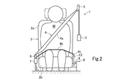
- FIG. 2 is a schematic view of the seat belt device when the seat belt is worn as viewed from the front in the vehicle front-rear direction.
- FIG. 3A is a diagram illustrating an example of the belt load by the seat belt device according to the embodiment
- FIG. 3B is a diagram illustrating an example of the belt load by the seat belt device according to the comparative example.
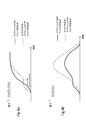
- 4A is a graph showing a change in tension applied to the shoulder belt
- FIG. 4B is a graph showing a change in tension applied to the lap belt.
- FIG. 1 is a configuration diagram of a seat belt device 1 according to an embodiment.
- FIG. 2 is a schematic view of the seat belt device 1 when the occupant wears the seat belt as viewed from the front in the vehicle front-rear direction.
- the seat belt device 1 is a three-point seat belt device, and includes a seat belt retractor 3 (hereinafter referred to as “retractor 3”), a seat belt 4, and a vehicle seat 2.
- a guide anchor 5, a tongue 6 and a buckle 7 are provided.
- the seat belt 4 is formed by webbing, is wound around the retractor 3 so as to be drawable, and restrains the occupant M in an emergency.
- the guide anchor 5 (shoulder anchor) guides the seat belt 4 pulled out from the retractor 3 toward the shoulder of the occupant M.
- the tongue 6 is slidably supported by the seat belt 4 guided from the guide anchor 5.
- the buckle 7 is fixed to the floor of the vehicle body or the vehicle seat 2, and the tongue 6 is inserted and engaged so as to be detachable.
- the seat belt 4 includes a shoulder belt 4a that restrains the shoulder and chest of the occupant M and a lap belt 4b that restrains the waist and the like of the occupant M.
- the seat belt 4 is partitioned by a tongue 6 into a shoulder belt 4a and a lap belt 4b.
- the seatbelt 4 mounting operation and mounting release operation in the seatbelt apparatus 1 are the same as those of a conventionally known seatbelt apparatus.
- the retractor 3 is a take-up device that enables the seat belt 4 to be taken up and pulled out, and restricts the seat belt 4 from being pulled out from the retractor 3 when acceleration of a predetermined value or more is detected in an emergency or the like. To do.
- the retractor 3 is provided with a load limiter mechanism (not shown) that keeps the restraining force of the seat belt 4 applied to the occupant M at a constant level.
- the pretensioner 8 is disposed on the opposite side of the buckle 7 with the vehicle seat 2 interposed therebetween, that is, on the passenger's boarding / exiting side of the vehicle.
- the main body 8a of the pretensioner 8 is fixed to a vehicle body frame 9 extending in the vehicle front-rear direction.
- the pretensioner 8 functions as a lap pretensioner, operates in the initial stage of an emergency, pulls and tensions the lap belt 4b, and increases the restraining force of the occupant M by the seat belt 4 (particularly, the lap belt 4b).
- a cylinder 8b and a gas generator 8c are connected to the main body 8a of the pretensioner 8.
- the gas generator 8c injects gas into the cylinder 8b when an acceleration of a predetermined value or more is detected.
- a piston (not shown) is provided so as to be airtight and slidable.
- the piston moves in the cylinder 8b by the gas injected from the gas generator 8c.
- This piston is connected to the front end 4c of the seat belt 4 through the connecting member 13. As the piston moves in the cylinder 8b, the lap belt 4b is pulled toward the main body 8a by the connecting member 13. Thereby, tension is applied to the seat belt 4 (particularly, the lap belt 4b), and the occupant M is restrained by the seat belt 4.
- the pretensioner provided in the seat belt device 1 is only the pretensioner 8 that functions as a lap pretensioner, and the retractor 3 and the buckle 7 are not provided with a pretensioner.
- the pretensioner 8 is activated to retract the seat belt 4.
- the pretensioner 8 By retracting the seat belt 4, slack between the occupant M and the seat belt 4 is removed, and the occupant M is restrained to the vehicle seat 2.
- the seat belt 4 As the seat belt 4 is retracted by the pretensioner 8, the seat belt 4 is pulled out from the retractor 3, and a pawl (not shown) rotates to engage (lock) the lock teeth. As a result, the rotation of the locking base (not shown) in the seat belt pull-out direction is locked.
- the load limiter of the retractor 3 is actuated to feed the seat belt 4 from the retractor 3.
- the seat belt 4 extends, and the load applied to the occupant M, particularly the chest of the occupant M, is alleviated.
- the tension (load) of the lap belt 4b is 2 ⁇ F1.
- a retractor 3A with a pretensioner is used, and the front end 4c of the seatbelt 4 is fixed to the floor of the vehicle body, a vehicle body frame, etc.
- the tension (load) of the shoulder belt 4a is 2 ⁇ F2
- the tension (load) of the lap belt 4b is 2 ⁇ F3 (F2> F3).
- the wrap pretensioner according to the present embodiment has the same tension (load) as that of the shoulder belt 4a as compared with the configuration in which the retractor is provided with the pretensioner.
- the tension (load) of the belt 4b can be increased.
- the pretensioner may be provided only in the lap anchor part, and the cost can be reduced as compared with the configuration in which the pretensioner is provided in both the retractor and the wrap anchor part.
- FIG. 4a shows a change in tension applied to the shoulder belt 4a when the seat belt 4 is pulled by the pretensioner 8 as shown in FIG. 3a and when the seat belt 4 is pulled by the pretensioner of the retractor 3A as shown in FIG. 3b. It is a graph which shows.
- FIG. 4b is a graph showing a change in tension applied to the lap belt 4b.
- the tension applied to the lap belt 4b is higher than that in the case where the seat belt 4 is wound up by the pretensioner of the retractor 3A. It can be launched quickly.
- the tension of the lap belt 4b quickly rises, the maximum tension thereafter decreases.
Landscapes
- Engineering & Computer Science (AREA)
- Mechanical Engineering (AREA)
- Automotive Seat Belt Assembly (AREA)
Abstract
ラップベルトによる乗員拘束力を効率良くかつ低コストに向上させることができるシートベルト装置を提供する。本発明のシートベルト装置は、シートベルト4と、シートベルト4を巻き取るリトラクタ3と、シートベルト4に摺動可能に支持されかつシートベルト4をショルダーベルト4aとラップベルト4bとに区画するタング6と、タング6が着脱されるバックル7と、緊急時に作動してリトラクタ3から引き出されるシートベルト4の先端部4cを引っ張り、シートベルト4に張力を付与するプリテンショナ8と、を備える。プリテンショナ8がラップベルト4bに付与する張力は、ショルダーベルト4aに付与する張力よりも大きい。
Description
本発明は、自動車等の車両に設けられ、車両衝突時等の緊急時にシートベルトのラップベルトを引っ張ることでシートベルトによる乗員の拘束力を高めるプリテンショナを備えるシートベルト装置に関する。
従来、自動車等の車両シートに付設されているシートベルト装置においては、衝突時等の車両に通常時より大きな減速度が作用した緊急時(以下、単に緊急時という)に、乗員がシートベルトにより拘束される。シートベルト装置として、一般に3点式シートベルト装置が広く知られている。例えば、3点式シートベルト装置では、リトラクタから引き出されたシートベルトがベルトガイドアンカでガイドされ、その先端が車体に固定される。ベルトガイドアンカでガイドされたシートベルトには、タングが摺動可能に支持されている。タングが車体に固定されたバックルに係合されることで、シートベルトが乗員に装着されるようになっている。
シートベルトが乗員に装着された状態では、ベルトガイドアンカとタングとの間のシートベルトが乗員の肩および胸に装着されるショルダーベルトとして機能する。また、車体に固定された先端とタングとの間のシートベルトが乗員のラップ(腰)に装着されるラップベルトとして機能する。緊急時には、リトラクタのロック機構が作動してシートベルトの引き出しが阻止されることにより、ショルダーベルトで乗員の肩および胸が拘束され、またラップベルトで乗員の腰が拘束される。
リトラクタにプリテンショナを設ける構成が知られている。緊急時の初期に、プリテンショナが作動してシートベルトの緩みを迅速に低減し、乗員の拘束効果を向上させている。このようなシートベルト装置において、ラップベルトによる乗員の腰部分の拘束力を向上させるには、プリテンショナの出力を大きくする必要があるが、ラップベルトによる拘束力以上に、ショルダーベルトによる拘束力が高まる。
ラップベルトによる拘束力が所望の値となるようにプリテンショナの出力を上げた場合、ショルダーベルトによる拘束力が所望の範囲以上に上昇することがあった。従来のシートベルト装置では、ショルダーベルトによる乗員拘束力を同程度に維持しつつ、ラップベルトによる乗員拘束力を効率良く向上させることは困難であった。
プリテンショナをリトラクタだけでなく、ラップアンカ部にも設けたシートベルト装置が提案されている(例えば特開2001-287622号公報参照)。緊急時には、まず、リトラクタのプリテンショナを作動してリトラクタでシートベルトを巻き取り、その後、ラップアンカ部のプリテンショナを作動してシートベルトを引っ張ることで、シートベルトの緩みを迅速に低減する。
このように、2つのプリテンショナを備えたシートベルト装置では、ラップアンカ部のプリテンショナの出力を上げることで、ラップベルトによる乗員拘束力を効率良く向上させることができる。しかし、プリテンショナを2つ設けることはコストを増加させるという問題があった。
本発明は、ラップベルトによる乗員拘束力を効率良くかつ低コストに向上させることができるシートベルト装置を提供することを目的とする。
本発明のシートベルト装置は、シートベルトと、前記シートベルトを巻き取るリトラクタと、前記シートベルトに摺動可能に支持されかつ前記シートベルトをショルダーベルトとラップベルトとに区画するタングと、前記タングが着脱されるバックルと、緊急時に作動して前記リトラクタから引き出されるシートベルトの先端部を引っ張り、前記シートベルトに張力を付与するプリテンショナと、を備え、前記プリテンショナが前記ラップベルトに付与する張力は、前記ショルダーベルトに付与する張力よりも大きいことを特徴とする。
本発明の一態様では、前記シートベルトの先端部にのみプリテンショナが設けられている。
本発明のシートベルト装置では、プリテンショナが、リトラクタから引き出されるシートベルトの先端部を引っ張るため、ラップベルトによる乗員拘束力を効率良く向上させることができる。また、シートベルトの先端部にのみプリテンショナが設けられているため、シートベルト装置のコストを抑えることができる。
以下、図面を参照して実施の形態について説明する。
図1は、実施の形態に係るシートベルト装置1の構成図である。図2は、乗員がシートベルトを装着した時のシートベルト装置1を車両前後方向の前方向から見た模式図である。
図1、図2に示す通り、シートベルト装置1は三点式シートベルト装置であり、車両シート2の近傍に配置されたシートベルトリトラクタ3(以下、「リトラクタ3」と記載する)、シートベルト4、ガイドアンカ5、タング6及びバックル7を備える。シートベルト4は、ウェビングで形成され、リトラクタ3に引き出し可能に巻き取られるとともに緊急時に乗員Mを拘束する。ガイドアンカ5(ショルダーアンカ)は、リトラクタ3から引き出されたシートベルト4を乗員Mのショルダの方へガイドする。タング6は、ガイドアンカ5からガイドされてきたシートベルト4に摺動自在に支持される。バックル7は、車体の床又は車両シート2に固定されかつタング6が係脱可能に挿入係合される。
シートベルト4は乗員Mの肩および胸等を拘束するショルダーベルト4aと、乗員Mの腰等を拘束するラップベルト4bとを含む。シートベルト4は、タング6によりショルダーベルト4aとラップベルト4bとに区画される。
このシートベルト装置1におけるシートベルト4の装着操作および装着解除操作は、従来公知のシートベルト装置と同じである。
リトラクタ3は、シートベルト4の巻き取り及び引き出しを可能にする巻き取り装置であって、緊急時等に所定値以上の加速度が検知されると、シートベルト4がリトラクタ3から引き出されることを制限する。リトラクタ3には、乗員Mに加わるシートベルト4の拘束力を一定レベルに保つロードリミッタ機構(図示略)が設けられている。
リトラクタ3から引き出されたシートベルト4の先端部4cは、連結部材13を介して、プリテンショナ8に接続されている。先端部4cは、シートベルト4のラップベルト4bからシートベルト4の先端側に続く部分である。
プリテンショナ8は車両シート2を挟んでバックル7と反対側、すなわち車両における乗員Mの乗降側に配置されている。プリテンショナ8の本体部8aは、車両前後方向に延在する車体フレーム9に固定されている。プリテンショナ8は、ラッププリテンショナとして機能し、緊急時の初期に作動してラップベルト4bを引っ張って緊張し、シートベルト4(特に、ラップベルト4b)による乗員Mの拘束力を高める。
プリテンショナ8の本体部8aには、シリンダ8b及びガスジェネレータ8cが連結されている。ガスジェネレータ8cは、所定値以上の加速度が検知されることによって、シリンダ8b内にガスを注入する。
シリンダ8b内にはピストン(図示略)が気密かつ摺動可能に設けられている。ガスジェネレータ8cから注入されたガスにより、このピストンがシリンダ8b内を移動する。
このピストンは、連結部材13を介して、シートベルト4の先端部4cに接続されている。ピストンがシリンダ8b内を移動することで、ラップベルト4bが連結部材13によって本体部8a側に引っ張られる。これにより、シートベルト4(特に、ラップベルト4b)に張力が付与されて、乗員Mはシートベルト4により拘束される。
シートベルト装置1に設けられるプリテンショナは、ラッププリテンショナとして機能するプリテンショナ8のみであり、リトラクタ3やバックル7にはプリテンショナは設けられていない。
このようなシートベルト装置1では、車両衝突時等の緊急時に、図示しないセンサにより所定値以上の加速度が検知されると、プリテンショナ8が作動し、シートベルト4を引き込む。シートベルト4を引き込むことで、乗員Mとシートベルト4との間のたるみを取り除き、乗員Mを車両シート2に拘束する。
プリテンショナ8によるシートベルト4の引き込みに伴い、リトラクタ3からシートベルト4が引き出され、パウル(図示略)が回動してロック歯に係合(ロック)する。これにより、ロッキングベース(図示略)のシートベルト引き出し方向の回転がロックされる。
その後、乗員Mが慣性力で前方に移動し始める。このとき、シートベルト4に所定の負荷がかかると、リトラクタ3のロードリミッタが作動してリトラクタ3からシートベルト4を送り出す。これにより、シートベルト4が伸びて、乗員M、特に乗員Mの胸部に加わる負荷が緩和される。
本実施の形態では、プリテンショナ8がラップベルト4bを引っ張るため、ラップベルトbによる乗員拘束力(張力)を、ショルダーベルト4aによる乗員拘束力(張力)よりも高くすることができる。
例えば、プリテンショナ8がF1の力でシートベルト4を引き込む場合、シートベルト4の各部には、図3aに示すような張力(荷重)がかかる。すなわち、ショルダーベルト4aの張力(荷重)は2×F2(F1>F2)となる。ラップベルト4bの張力(荷重)は2×F1となる。
一方、図3bに示すように、プリテンショナ付のリトラクタ3Aを使用し、シートベルト4の先端部4cを車体の床や車体フレーム等に固定し、リトラクタ3AのプリテンショナによりF1の力でシートベルト4を引き込む場合、ショルダーベルト4aの張力(荷重)は2×F2となり、ラップベルト4bの張力(荷重)は2×F3(F2>F3)となる。
このように、同パワーのプリテンショナを使用した場合でも、ラッププリテンショナとした本実施形態は、リトラクタにプリテンショナを設ける構成と比較して、ショルダーベルト4aの張力(荷重)は同じまま、ラップベルト4bの張力(荷重)を上げることができる。プリテンショナは、ラップアンカ部にのみ設ければよく、リトラクタとラップアンカ部の両方にプリテンショナを設ける構成と比較して、コストを削減できる。
図4aは、図3aに示すようにプリテンショナ8でシートベルト4を引き込む場合と、図3bに示すようにリトラクタ3Aのプリテンショナでシートベルト4を引き込む場合の、ショルダーベルト4aにかかる張力の変化を示すグラフである。
図3bに示す構成では、リトラクタ3Aのプリテンショナでシートベルト4を巻き取った後、パウルがロックするまでにシートベルト4が僅かにリトラクタ3Aから引き出される(ロックペイアウト)。そのため、図4aに示すように、ショルダーベルト4aにかかる張力が低下する期間がある。
一方、本実施形態によれば、プリテンショナ8がシートベルト4を巻き取る際にロックペイアウトの分も巻き取り、パウルがロックする。そのため、ショルダーベルト4aにかかる張力が低下することなく速やかに立ち上がる。
図4bはラップベルト4bにかかる張力の変化を示すグラフである。本実施形態によれば、ラップアンカ部に設けたプリテンショナ8でシートベルト4を巻き取るため、リトラクタ3Aのプリテンショナでシートベルト4を巻き取る場合と比較して、ラップベルト4bにかかる張力を速やかに立ち上げることができる。また、ラップベルト4bの張力が速やかに立ち上がることで、その後の最大張力が低くなる。
上記実施の形態は、いずれも本発明の一例であり、本発明は図示の状態に限定されない。
本出願は、2016年5月27日付で出願された日本特許出願2016-106499に基づいており、その全体が引用により援用される。
本出願は、2016年5月27日付で出願された日本特許出願2016-106499に基づいており、その全体が引用により援用される。
Claims (2)
- シートベルトと、
前記シートベルトを巻き取るリトラクタと、
前記シートベルトに摺動可能に支持されかつ前記シートベルトをショルダーベルトとラップベルトとに区画するタングと、
前記タングが着脱されるバックルと、
緊急時に作動して前記リトラクタから引き出されるシートベルトの先端部を引っ張り、前記シートベルトに張力を付与するプリテンショナと、
を備え、
前記プリテンショナが前記ラップベルトに付与する張力は、前記ショルダーベルトに付与する張力よりも大きいことを特徴とするシートベルト装置。 - 請求項1において、前記シートベルトの先端部にのみプリテンショナが設けられていることを特徴とするシートベルト装置。
Applications Claiming Priority (2)
| Application Number | Priority Date | Filing Date | Title |
|---|---|---|---|
| JP2016-106499 | 2016-05-27 | ||
| JP2016106499A JP2017210211A (ja) | 2016-05-27 | 2016-05-27 | シートベルト装置 |
Publications (1)
| Publication Number | Publication Date |
|---|---|
| WO2017204010A1 true WO2017204010A1 (ja) | 2017-11-30 |
Family
ID=60411245
Family Applications (1)
| Application Number | Title | Priority Date | Filing Date |
|---|---|---|---|
| PCT/JP2017/018152 Ceased WO2017204010A1 (ja) | 2016-05-27 | 2017-05-15 | シートベルト装置 |
Country Status (2)
| Country | Link |
|---|---|
| JP (1) | JP2017210211A (ja) |
| WO (1) | WO2017204010A1 (ja) |
Citations (9)
| Publication number | Priority date | Publication date | Assignee | Title |
|---|---|---|---|---|
| JP2002527281A (ja) * | 1998-10-13 | 2002-08-27 | ブリード・オートモーティブ・テクノロジイ・インコーポレーテッド | シート・ベルト・プレテンショナ |
| JP2004106651A (ja) * | 2002-09-17 | 2004-04-08 | Takata Corp | 乗員保護装置 |
| JP2004322737A (ja) * | 2003-04-22 | 2004-11-18 | Honda Motor Co Ltd | シートベルトプリテンショナのカバー構造 |
| JP2006199197A (ja) * | 2005-01-21 | 2006-08-03 | Mazda Motor Corp | ラップアウタプリテンショナーの配設構造 |
| JP2012066804A (ja) * | 2010-08-25 | 2012-04-05 | Mazda Motor Corp | 車両の車体下部構造 |
| US20130099471A1 (en) * | 2011-10-21 | 2013-04-25 | Tk Holdings Inc. | Seatbelt to pretensioner connector assembly |
| JP2014028601A (ja) * | 2012-07-31 | 2014-02-13 | Takata Corp | ラッププリテンショナ装置及びそれを備えるシートベルト装置 |
| JP2014113931A (ja) * | 2012-12-10 | 2014-06-26 | Mitsubishi Automob Eng Co Ltd | ラッププリテンショナの取付け構造 |
| US20140265290A1 (en) * | 2013-03-15 | 2014-09-18 | Autoliv Asp, Inc. | Reduced width linear pretensioner for motor vehicle seatbelt restraint systems |
-
2016
- 2016-05-27 JP JP2016106499A patent/JP2017210211A/ja active Pending
-
2017
- 2017-05-15 WO PCT/JP2017/018152 patent/WO2017204010A1/ja not_active Ceased
Patent Citations (9)
| Publication number | Priority date | Publication date | Assignee | Title |
|---|---|---|---|---|
| JP2002527281A (ja) * | 1998-10-13 | 2002-08-27 | ブリード・オートモーティブ・テクノロジイ・インコーポレーテッド | シート・ベルト・プレテンショナ |
| JP2004106651A (ja) * | 2002-09-17 | 2004-04-08 | Takata Corp | 乗員保護装置 |
| JP2004322737A (ja) * | 2003-04-22 | 2004-11-18 | Honda Motor Co Ltd | シートベルトプリテンショナのカバー構造 |
| JP2006199197A (ja) * | 2005-01-21 | 2006-08-03 | Mazda Motor Corp | ラップアウタプリテンショナーの配設構造 |
| JP2012066804A (ja) * | 2010-08-25 | 2012-04-05 | Mazda Motor Corp | 車両の車体下部構造 |
| US20130099471A1 (en) * | 2011-10-21 | 2013-04-25 | Tk Holdings Inc. | Seatbelt to pretensioner connector assembly |
| JP2014028601A (ja) * | 2012-07-31 | 2014-02-13 | Takata Corp | ラッププリテンショナ装置及びそれを備えるシートベルト装置 |
| JP2014113931A (ja) * | 2012-12-10 | 2014-06-26 | Mitsubishi Automob Eng Co Ltd | ラッププリテンショナの取付け構造 |
| US20140265290A1 (en) * | 2013-03-15 | 2014-09-18 | Autoliv Asp, Inc. | Reduced width linear pretensioner for motor vehicle seatbelt restraint systems |
Also Published As
| Publication number | Publication date |
|---|---|
| JP2017210211A (ja) | 2017-11-30 |
Similar Documents
| Publication | Publication Date | Title |
|---|---|---|
| JP4621281B2 (ja) | シートベルトプリテンショナー | |
| CN100515837C (zh) | 安全带收紧器 | |
| US5667246A (en) | Method and apparatus for reducing occupant injury in frontal collisions | |
| US6840544B2 (en) | Restraint system tensioning device with load limiting capability | |
| CN103221260B (zh) | 附安全带座椅的座椅靠背移动防止装置 | |
| US10703332B2 (en) | Three-point seatbelt device | |
| JP2006290053A (ja) | シートベルト装置 | |
| CN106080497A (zh) | 座椅安全带卷收器及座椅安全带装置 | |
| US7232155B2 (en) | Seatbelt apparatus | |
| US7237800B2 (en) | Occupant protection system | |
| CN107933494B (zh) | 预紧器和包括该预紧器的安全带组件 | |
| US10399539B2 (en) | Pretensioner and safety belt assembly having the same | |
| CN105383436B (zh) | 具有楔形夹具和负荷限制器的座椅安全带伸缩器 | |
| JP2002211354A (ja) | プリテンショナ装置 | |
| JP6284501B2 (ja) | シートベルト装置 | |
| JP2001287622A (ja) | 車両のシートベルトプリテンショナー作動方法 | |
| WO2017204010A1 (ja) | シートベルト装置 | |
| JP2002211352A (ja) | プリテンショナ装置 | |
| JP2009161144A (ja) | プリテンショナ及びシートベルト装置 | |
| JP5420264B2 (ja) | 車両用シート | |
| JP2022071614A (ja) | バックルプリテンショナ及びシートベルト装置 | |
| JP2018184082A (ja) | シートベルト装置 | |
| JP5314442B2 (ja) | プリテンショナを備えるシートベルト装置 | |
| JP6273926B2 (ja) | シートベルト装置 | |
| CN112203909A (zh) | 安全带卷收器 |
Legal Events
| Date | Code | Title | Description |
|---|---|---|---|
| 121 | Ep: the epo has been informed by wipo that ep was designated in this application |
Ref document number: 17802604 Country of ref document: EP Kind code of ref document: A1 |
|
| NENP | Non-entry into the national phase |
Ref country code: DE |
|
| 122 | Ep: pct application non-entry in european phase |
Ref document number: 17802604 Country of ref document: EP Kind code of ref document: A1 |