WO2017195263A1 - 永久磁石型モータ - Google Patents
永久磁石型モータ Download PDFInfo
- Publication number
- WO2017195263A1 WO2017195263A1 PCT/JP2016/063825 JP2016063825W WO2017195263A1 WO 2017195263 A1 WO2017195263 A1 WO 2017195263A1 JP 2016063825 W JP2016063825 W JP 2016063825W WO 2017195263 A1 WO2017195263 A1 WO 2017195263A1
- Authority
- WO
- WIPO (PCT)
- Prior art keywords
- permanent magnet
- hole
- rotor core
- type motor
- magnet type
- Prior art date
Links
Images


Classifications
-
- H—ELECTRICITY
- H02—GENERATION; CONVERSION OR DISTRIBUTION OF ELECTRIC POWER
- H02K—DYNAMO-ELECTRIC MACHINES
- H02K1/00—Details of the magnetic circuit
- H02K1/06—Details of the magnetic circuit characterised by the shape, form or construction
- H02K1/22—Rotating parts of the magnetic circuit
- H02K1/27—Rotor cores with permanent magnets
- H02K1/2706—Inner rotors
- H02K1/272—Inner rotors the magnetisation axis of the magnets being perpendicular to the rotor axis
- H02K1/274—Inner rotors the magnetisation axis of the magnets being perpendicular to the rotor axis the rotor consisting of two or more circumferentially positioned magnets
- H02K1/2753—Inner rotors the magnetisation axis of the magnets being perpendicular to the rotor axis the rotor consisting of two or more circumferentially positioned magnets the rotor consisting of magnets or groups of magnets arranged with alternating polarity
- H02K1/276—Magnets embedded in the magnetic core, e.g. interior permanent magnets [IPM]
- H02K1/2766—Magnets embedded in the magnetic core, e.g. interior permanent magnets [IPM] having a flux concentration effect
-
- H—ELECTRICITY
- H02—GENERATION; CONVERSION OR DISTRIBUTION OF ELECTRIC POWER
- H02K—DYNAMO-ELECTRIC MACHINES
- H02K2213/00—Specific aspects, not otherwise provided for and not covered by codes H02K2201/00 - H02K2211/00
- H02K2213/03—Machines characterised by numerical values, ranges, mathematical expressions or similar information
-
- H—ELECTRICITY
- H02—GENERATION; CONVERSION OR DISTRIBUTION OF ELECTRIC POWER
- H02K—DYNAMO-ELECTRIC MACHINES
- H02K29/00—Motors or generators having non-mechanical commutating devices, e.g. discharge tubes or semiconductor devices
- H02K29/03—Motors or generators having non-mechanical commutating devices, e.g. discharge tubes or semiconductor devices with a magnetic circuit specially adapted for avoiding torque ripples or self-starting problems
Definitions
- the present invention relates to a permanent magnet type motor provided with a permanent magnet for constituting a field pole, and more particularly to a permanent magnet type motor having a permanent magnet for constituting a field pole embedded in a rotor.
- IPM Interior Permanent Magnet
- SPM Surface Permanent Magnet
- Patent Document 1 and Patent Document 2 Conventional permanent magnet type motors disclosed in Patent Document 1 and Patent Document 2 can be used for various applications.
- the permanent magnet motor is used in an environment where the motor is used, for example, an electric power steering device that assists the steering of a vehicle driver.
- the operating sound and vibration when the permanent magnet motor is driven are transmitted to the driver, and in some cases, the driver may feel uncomfortable. Therefore, the conventional permanent magnet type motor has a problem that even if torque ripple and cogging torque are reduced as described above, it is necessary to further reduce operation noise and vibration during driving depending on the application. It was.
- the present invention has been made to solve the above-mentioned problems in the conventional permanent magnet type motor, and provides a permanent magnet type motor that can further reduce operation noise and vibration during driving. With the goal.
- the permanent magnet type motor is: A stator core in which a plurality of electromagnetic steel plates are laminated in the axial direction, and teeth and slots are alternately formed in the circumferential direction; An armature coil including a conductor inserted into the slot and mounted on the stator core; A plurality of electromagnetic steel plates are laminated in the axial direction, and a rotor core arranged so that an outer peripheral surface opposes the inner peripheral surface of the stator core via a predetermined gap; A plurality of permanent magnets embedded in the rotor core and forming a plurality of field poles in the rotor core; A permanent magnet motor with The armature coil is constituted by at least two sets of coils having substantially the same configuration,
- the rotor core is A plurality of through holes arranged at intervals around the axis of the rotor core; A plurality of through-hole enlarged portions provided respectively connected to the plurality of through-holes; A bridge portion located at a boundary portion between the adjacent field poles and surrounding the adjacent through-
- the armature coil is constituted by at least two sets of coils having substantially the same configuration
- the rotor core has a plurality of through holes arranged at intervals around the axis of the rotor core. And a part of the outer peripheral surface of the rotor core that surrounds each through-hole enlarged part of the adjacent through-hole, located at the boundary part between adjacent through-holes, and the through-hole enlarged part provided in each of the plurality of through-holes
- the plurality of permanent magnets are individually inserted into the plurality of through-holes and embedded in the rotor core, and the bridge portion is located in a portion other than the bridge portion in the rotor core.
- production of a vibration can be suppressed.
- FIG. 1 is an axial sectional view of a permanent magnet type motor according to Embodiment 1 of the present invention.
- the permanent magnet type motor shown in FIG. 1 is used, for example, in an electric power steering device for a vehicle.
- a permanent magnet type motor (hereinafter simply referred to as a motor) 2 shown in FIG. 1 is an IPM motor, and can be broadly divided into a cylindrical motor case 25 and an inner peripheral surface of the motor case 25.
- the stator 22 fixed to the rotor 22, the rotor 23 disposed so that the outer peripheral surface faces the inner peripheral surface of the stator 22 with a predetermined gap, the rotor shaft 40 to which the rotor 23 is fixed, and the motor case
- the frame 28 is disposed so as to close one end portion 251 in the axial direction of the opened motor case 25, and the outer peripheral surface is in contact with the inner peripheral surface of the motor case 25 and is fixed to the motor case 25.
- the first bearing 51 is inserted into a through hole 282 provided in the central portion in the radial direction of the frame 28 and is held by the frame 28.
- a wall 253 that closes the other end 252 of the motor case 25 is formed integrally with the motor case 25.
- the second bearing 52 is inserted into a through hole 254 provided at the radial center portion of the wall portion 253 of the motor case 25 and held by the wall portion 253.
- One end portion 41 in the axial direction of the rotor shaft 40 is rotatably supported by the first bearing 51, and the other end portion 42 in the axial direction of the rotor shaft 40 is freely rotatable by the second bearing 52. It is supported.
- the output shaft 21 is fixed to the other axial end portion 42 of the rotor shaft 40 and is connected to, for example, a speed reduction mechanism (not shown).
- the stator 22 includes a stator core 22a configured by laminating a large number of electromagnetic steel plates in the axial direction, and an armature coil 24 mounted on the stator core 22a as described later.
- the armature coil 24 is composed of two sets of three-phase armature coils having substantially the same configuration.
- the rotor 23 includes a rotor core 23a configured by laminating a large number of electromagnetic steel plates in the axial direction, and a multi-pole pair permanent magnet, which will be described later, embedded in the rotor core 23a.
- the rotor 23 is fixed to the rotor shaft 40 by passing through the rotor shaft 40 at the center in the radial direction.
- connection ring 27 includes a holder 271 configured in an annular shape by an insulator, and a plurality of annular connection conductors 272 inserted into a concave groove formed in the holder 271 and fixed to the holder 271.
- the connection ring 27 is disposed in the immediate vicinity of the armature coil 24 and is fixed to a support body 60 fixed to one axial end of the stator 22.
- the support 60 made of an insulator is fixed to both ends of the stator 24 in the axial direction, and supports the end of the armature coil 24 in the axial direction.
- the two sets of three-phase armature coils constituting the armature coil 24 are respectively connected to a three-phase ⁇ connection or a three-phase Y connection by a connection ring 27.
- the first winding end portion 26 a made of three conductors is connected to each phase winding of one of the three-phase armature coils of the two sets of three-phase armature coils via the connection conductor 272 of the connection ring 27.
- One end is connected, and the other end is connected to the connector 30 via a first through hole 28a of the frame 28 and a through hole (not shown) of the bracket 29.
- the second winding end portion 26 b made of three conductors is connected to each phase winding of the other three-phase armature coil of the two sets of three-phase armature coils via the connection conductor 272 of the connection ring 27.
- One end is connected, and the other end is connected to the connector 30 via a second through hole 28b of the frame 28 and a through hole (not shown) of the bracket 29.
- the connector 30 is fixed to the bracket 29, and connects the first winding end portion 26a and the second winding end portion 26b to a power conversion device (not shown) such as an inverter via the cable 31. To do.
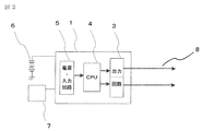
- FIG. 2 is an explanatory diagram of a control unit in the permanent magnet type motor according to Embodiment 1 of the present invention.
- the control unit 1 includes a power source / input circuit 5, a CPU (central processing unit) 4 that calculates a control amount, and an output circuit 3.
- the power source / input circuit 5 is connected to an external power source 6 such as a battery mounted on a vehicle or the like, and supplies power from the external power source 6 to the UPU 4 and the output circuit 3, and various types provided in the vehicle or the like. And an input circuit connected to the sensor 7.
- an external power source 6 such as a battery mounted on a vehicle or the like
- an input circuit connected to the sensor 7.
- the CPU 4 calculates and outputs a control amount for controlling the output of the output circuit based on various information input from the various sensors 7 via the power source / input circuit 5, for example, information such as vehicle speed and steering torque. This is given to the circuit 3.
- the output circuit 3 includes, for example, a power conversion circuit composed of a three-phase bridge circuit composed of a plurality of switching elements and the like. A three-phase output current controlled based on the controlled amount is generated.
- the output current output from the output circuit 3 of the control unit 1 is supplied to the cable 31 shown in FIG.
- the output current from the output circuit 3 supplied to the cable 31 is supplied to one of the three-phase armature coils constituting the armature coil 24 via the connector 30 and the first winding end portion 26a.
- the output current from the output circuit 3 supplied to the cable 31 is supplied to the other three-phase armature coil constituting the armature coil 24 via the connector 30 and the second winding end portion 26b.
- the control unit 1 transmits various information from the sensors 7 to the CPU 4 via the power source / input circuit 5, calculates a control amount and outputs it to the output circuit 3.
- a three-phase current is supplied to the armature coil 24.
- a phase current having a phase difference of 120 degrees is supplied to the coils of each phase in one of the three-phase armature coils and the other three-phase armature coil constituting the armature coil 24,
- One three-phase armature coil and the other three-phase armature coil are supplied with a three-phase current whose phase is shifted by, for example, an electrical angle of 30 degrees.
- the control unit 1 controls the driving of the output circuit 3 based on the control amount calculated by the CPU 4, thereby controlling various motors such as the control of the rotational speed of the output shaft 21 of the motor 2 and the control of the output torque. It can be carried out.
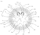
- FIG. 3 is a cross-sectional view perpendicular to the axial direction of the permanent magnet type motor according to Embodiment 1 of the present invention
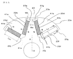
- FIG. 4A is the rotor of the permanent magnet type motor according to Embodiment 1 of the present invention. It is explanatory drawing of these, Comprising: A part of rotor 23 shown in FIG. 3 is expanded and shown. 3 and 4A, the stator core 22a of the stator 22 includes 48 slots 22b and 48 teeth 22c positioned between adjacent slots 22b. Four coil conductors 24a constituting the armature coil 24 are inserted into each slot 22b.
- the stator core 22a is configured by laminating a large number of electromagnetic steel sheets in the axial direction. At least a part of the electromagnetic steel sheets, for example, half of the electromagnetic steel sheets, are connected to each other at the tips of adjacent teeth 22c. It is configured to be. Thereby, especially cogging torque can be reduced.
- the rotor core 23a is configured by laminating a large number of electromagnetic steel plates in the axial direction, and is disposed so as to be symmetrically inclined at a predetermined angle with respect to the radial line X that intersects the axis O of the rotor core 23a.
- Eight pairs of through-hole pairs 231 formed of the first through-holes 23b and the second through-holes 23c are arranged at intervals of 45 degrees around the axis.
- Each of the eight through-hole pairs 231 is arranged in a V shape so that the interval facing the outer side in the radial direction of the rotor core 23a is smaller than the interval facing the inner side in the radial direction of the rotor core 23a.
- Each through-hole has a substantially rectangular cross-sectional shape having a pair of long sides facing each other and a pair of short sides facing each other.
- the first through hole 23b and the second through hole 23c in the eight through hole pairs 231 have a first permanent magnet 41a and a second permanent magnet 41b each having a substantially rectangular cross section. Are inserted individually. More specifically, in the first permanent magnet 41a and the second permanent magnet 41b, one end surface portion constituting one magnetic pole is opposed to one long side portion of the through hole, and the other constituting the other magnetic pole. Is inserted into the through-hole so that the end surface portion thereof faces the other long side portion of the through-hole.
- the first permanent magnet 41a and the second permanent magnet 41b inserted into the two adjacent through-hole pairs 231 and 231 respectively constitute a first permanent magnet pair 410 and a second permanent magnet pair 411.
- the first permanent magnet pair 410 including the first permanent magnet 41 a and the second permanent magnet 41 b and the second permanent magnet pair 411 are provided only in the two adjacent through-hole pairs 231.
- the first permanent magnet 41a is inserted into the other six through holes 231, the first permanent magnet pair 410 including the first permanent magnet 41a and the second permanent magnet 41b, and the second permanent magnet 41b. Permanent magnet pairs 411 are alternately inserted.
- the plurality of permanent magnets constitute a plurality of permanent magnet pairs arranged so that the end surfaces of different polarities are substantially opposed to each other, and the respective permanent magnet pairs are opposed to each other on the outer side in the radial direction of the rotor core 23a.
- positions at V shape so that it may become smaller than the space
- the first permanent magnet 41a in the first permanent magnet pair 410 shown in FIG. 3 is magnetized so that the left end surface portion in the drawing is the S pole and the right end surface portion is the N pole
- the second permanent magnet 41b is magnetized so that the left end face in the figure is an S pole and the right end face is an N pole
- the first permanent magnet 41a in the second permanent magnet pair 411 is magnetized so that the left end face portion in the drawing has an N pole and the right end face portion has an S pole
- the second permanent magnet 41b has The left end face in the figure is magnetized so as to be an N pole and the right end face is an S pole.
- the first permanent magnet pairs 410 and the second permanent magnet pairs 411 are alternately arranged around the axis of the rotor 23.
- the end face of the N pole of the first permanent magnet 41a faces the end face of the S pole of the second permanent magnet 41b.
- the end surface portion of the S pole of the first permanent magnet 41a faces the end surface portion of the N pole of the second permanent magnet 41b.
- the end surface portion of the N pole of the second permanent magnet 41 b in the first permanent magnet pair 410 is opposed to the end surface portion of the N pole of the first permanent magnet 41 a in the second permanent magnet pair 411. is doing.
- the end face of the S pole of the first permanent magnet 41a in the first permanent magnet pair 410 is the end face of the S pole of the second permanent magnet in the second permanent magnet pair on the left side not shown. It faces the part.
- the end face of the S pole of the second permanent magnet 41b in the second permanent magnet pair 411 is the end face of the S pole of the first permanent magnet in the first permanent magnet pair on the right side (not shown). It faces the part. The same applies to other first permanent magnet pairs and second permanent magnet pairs not shown.
- the rotor core 23a includes a portion where the first permanent magnet 41a and the second permanent magnet 41b in the first permanent magnet pair 410 face each other at a narrow interval in the vicinity of the outer peripheral surface of the rotor core 23a, and the second permanent magnet.
- the first permanent magnet 41a and the second permanent magnet 41b in the pair 411 are provided with bridge portions 23e that respectively surround portions facing each other at a narrow interval in the vicinity of the outer peripheral surface of the rotor core 23a.
- the rotor core 23a includes a field pole 23d in which the first permanent magnet pair 410 and the second permanent magnet pair 411 are opposed to each other at a wide interval in the vicinity of the outer peripheral surface of the rotor core 23a.
- the bridge portion 23e is located at a boundary portion between adjacent field poles 23d.
- the rotor core 23a is not a perfect circle, and the radius of the rotor core 23a in the bridge portion 23e is smaller than the radius of the rotor core 23a in the portion other than the bridge portion 23e. Further, the rotor core 23a in the field pole 23d has a maximum radius at the center thereof, and is configured such that the radius decreases as the bridge portion 23e is approached.
- the field pole 23d is sandwiched between end faces of permanent magnets having the same polarity, and constitutes an N-pole or S-pole field pole.
- the N pole end surface portion of the second permanent magnet 41 b in the first permanent magnet pair 410 and the N pole end surface portion of the first permanent magnet 41 a in the second permanent magnet pair 411 are arranged.
- the sandwiched field pole 23d constitutes an N pole, the end face of the S pole of the first permanent magnet 41a in the first permanent magnet pair 410, and the second permanent magnet pair on the left side.
- the field pole 23d sandwiched between the end faces of the S pole of the second permanent magnet constitutes the S pole.
- N-pole field poles 23 d and S-pole field poles 23 d are alternately arranged on the peripheral surface portion of the rotor 23.
- the first through hole 23b and the second through hole 23c each have a substantially rectangular cross-sectional shape having a pair of long side portions facing each other and a pair of short side portions facing each other.
- the one permanent magnet 41a and the second permanent magnet 41b have one end surface portion constituting one magnetic pole facing one long side portion of the first through hole 23b or the second through hole 23c, and the other The other end surface part which comprises a magnetic pole is inserted in each through-hole so that the other long side part of a through-hole may be opposed.
- the through-hole enlarged portion 23g is provided to be connected to the first through-hole 23b and the second through-hole 23c, respectively.
- the through-hole enlarged portion 23g forms an enlarged space in contact with the end surface portion on the circumferential surface portion side of the rotor core 23a in the corresponding first permanent magnet 41a and second permanent magnet 41b.
- the through-hole enlarged portions 23g in the first through-hole 23b and the second through-hole 23c and the bridge portion 23e in the rotor core 23a have an important role in the flow of magnetic flux as will be described later. ing.
- the armature coil 24 attached to the stator core 22a is energized by the current from the control unit 1 to generate a magnetic flux that flows through the teeth 22c, and N and S rotating magnetic fields are generated in the stator 22.
- the rotor 23 is rotated by the attractive force and the repulsive force with the N pole and the S pole formed on the field pole 23d of the rotor 23.
- the magnetic flux generated from the N pole of the second permanent magnet 41b in the first permanent magnet pair 410 and the N pole of the first permanent magnet 41a in the second permanent magnet pair 411 is The field pole 23d of the rotor core 23a sandwiched between the permanent magnet pair 410 and the second permanent magnet pair 411 reaches the field pole 23d on the left side through the gap between the rotor 23 and the stator 22, and the first permanent magnet In the magnet pair 410, the magnetic field flows from the first permanent magnet 41a to the S pole of the first permanent magnet 41a, and between the field pole 23d sandwiched between the first permanent magnet pair 410 and the second permanent magnet pair 411 and the rotor 23. It reaches the field pole 23d on the right side through a gap with the stator 22 and flows in a magnetic path reaching the S pole of the second permanent magnet 41b in the second permanent magnet pair 411.
- the magnetic flux generated from the N pole of the first permanent magnet 41a is transferred to the magnetic path reaching the S pole of the adjacent second permanent magnet 41b via the rotor core 23a.
- the magnetic flux generated from the N pole of the second permanent magnet 41b flows through the magnetic pole reaching the S pole of the first permanent magnet 41a via the field pole 23d of the rotor core 23 and the bridge portion 23e.
- the magnetic flux generated from the N pole of the first permanent magnet 41a is transferred to the S pole of the second permanent magnet 41b via the field pole 23d and the bridge portion 23e of the rotor core 23a.
- the magnetic flux generated from the N pole of the second permanent magnet 41b flows through the magnetic path to the S pole of the adjacent first permanent magnet 41a via the rotor core 23a.
- the amount of magnetic flux flowing in the first magnetic path including the gap between the rotor 23 and the stator 22 is only the amount of magnetic flux flowing in the second magnetic path including the bridge portion 23e of the rotor core 23 without including the gap. Will be reduced. As a result, the amount of magnetic flux emitted from the field magnetic pole 23d of the rotor 23 to the gap is reduced, and the rotational speed and torque at which the rotor 23 rotates is reduced.
- the bridge portion 23e of the rotor core 23d is provided with a thin portion having a smaller cross-sectional area than the field pole 23d of the rotor core 23a.
- the magnetic resistance of the second magnetic path passing through the bridge portion 23e is increased, and the amount of magnetic flux flowing through the second magnetic path is reduced.
- the amount of magnetic flux released into the gap between the rotor 23 and the stator 22, that is, the amount of magnetic flux flowing through the first magnetic path described above increases.
- Wb is the minimum radial width of the rotor core 23a in the bridge portion 23e
- tb is the thickness of the electromagnetic steel plate in the bridge portion 23e
- tr is the thickness in a portion other than the bridge portion 23e of the electromagnetic steel plate.
- the magnetic resistance of the second magnetic path is increased by forming the thin portion according to the above (1).
- the magnetic flux flowing through the second magnetic path can be suppressed.
- the electromagnetic steel plate constituting the rotor core 23 is configured such that the thickness of the electromagnetic steel plate is different between the bridge portion 23e and the other portion, and the thin portion is formed by the above (2), whereby the above-mentioned second The magnetic resistance of the magnetic path is increased, and the magnetic flux flowing through the second magnetic path can be suppressed.
- the length of the pair of opposing surface portions in the first through hole 23b and the second through hole 23c is Lc, and the length Lm of each end surface portion in the first permanent magnet 41a and the second permanent magnet 41b.
- Lc Lm It is configured to satisfy. This prevents the magnetic flux flowing between the end face portions of the first permanent magnet 41a and the second permanent magnet 41b and the rotor core 23 from being suppressed by the space portion of the through-hole expanding portion 3g. Because.
- the first permanent magnet 41a and the second permanent magnet 41b are arranged at the inner diameter of the rotor core 23a at the position facing the inner side in the radial direction of the rotor 23.
- the side through hole 23j may be formed.
- the inner diameter side through holes 23j may be provided separately so as to correspond to the first permanent magnet 41a and the second permanent magnet 41b, respectively.
- the inner diameter side through hole 23j may or may not be connected to the first through hole 23b and the second through hole 23c.
- the inner diameter side through hole 23j can suppress the flow of the magnetic flux directly between the adjacent first permanent magnet 41a and the second permanent magnet 41b in the same manner as the above-described through hole enlarged portion 23g.
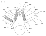
- FIG. 4B is an explanatory diagram of a rotor in a permanent magnet type motor according to a modification of the first embodiment of the present invention.
- the 1st through-hole 23b which inserts the 1st permanent magnet 41a
- the 2nd through-hole 23c which inserts the 2nd permanent magnet 41b
- the shape is different.
- the first through hole 23b is formed such that the length Lc of the opposing surface portion on the left side of the drawing is smaller than the length Lc of the opposing surface portion on the right side of the drawing
- the second through hole 23c is The length Lc of the opposing surface portion on the right side of the drawing is formed to be smaller than the length Lc of the opposing surface portion on the left side of the drawing.
- the through-hole enlarged portion 23g connected to the first through-hole 23b is enlarged to the middle of the left end surface portion of the first permanent magnet 41a and is connected to the second through-hole 23c.
- the through-hole expanding portion 23g thus expanded is expanded up to the middle of the right end surface portion of the second permanent magnet 41a.
- the length Lc of the opposite end face on the right side of the drawing of the first through-hole 23b is substantially equal to the length Lm of the right end face portion of the drawing of the first permanent magnet 41a, but the end face on the left side of the drawing.
- the length Lc of the portion is relative to the length Lm of the left end surface portion of the first permanent magnet 41a in the drawing. Lc ⁇ Lm It is formed to become.
- the length Lc of the opposing surface portion on the left side of the drawing of the second through hole 23c is substantially equal to the length Lm of the end surface portion on the left side of the drawing of the first permanent magnet 41a.
- the length Lc of the surface portion is relative to the length Lm of the right end surface portion of the first permanent magnet 41a. Lc ⁇ Lm It is formed to become.
- the amount of magnetic flux flowing from the end face of the N pole in the first permanent magnet 41a and the second permanent magnet 41b to the field pole 23d of the rotor core 23a is suppressed, and the first permanent magnet 41a from the field pole 23d of the rotor core 23a is suppressed.
- the magnet 41a and the second permanent magnet 41b the amount of magnetic flux flowing through the end face of the south pole is suppressed.
- the first permanent magnet 41a and the second permanent magnet 41b have an inner diameter at a position of the rotor core 23a at a position facing the inner side in the radial direction of the rotor 23.
- the side through hole 23j may be formed.
- the inner diameter side through hole 23j may be provided separately so as to correspond to the first permanent magnet 41a and the second permanent magnet 41b, respectively.
- the inner diameter side through hole 23j may or may not be connected to the first through hole 23b and the second through hole 23c.
- the inner diameter side through hole 23j can suppress the flow of the magnetic flux directly between the adjacent first permanent magnet 41a and the second permanent magnet 41b in the same manner as the above-described through hole enlarged portion 23g.
- the conventional permanent magnet type motor is configured so that the cogging torque and torque ripple phase generated by each permanent magnet is canceled by the entire rotor.
- the torque is reduced. There is a problem that the ripple becomes large.
- a motor that can reduce torque ripple by providing a thin wall portion in the outer peripheral shape of the rotor and the bridge portion in the vicinity of the through hole in which the permanent magnet is embedded.
- the cogging torque can be further reduced, resulting in motor vibration and noise during driving. Can be suppressed.
- FIG. 5 is an explanatory diagram of a rotor in a permanent magnet type motor according to the second embodiment of the present invention, and the same or equivalent parts as those in the first embodiment are denoted by the same reference numerals.
- the plurality of permanent magnets 41 are arranged so as to form a polygonal shape in the vicinity of the outer peripheral surface of the rotor core 23 da, and constitute the magnetic poles of the permanent magnet 41.
- the end surface portion to be arranged is arranged in a direction orthogonal to the radial direction of the rotor core 23a.
- Each permanent magnet 41 is magnetized in the reverse polarity with respect to the adjacent permanent magnet 41 as shown in FIG.
- a bridge portion 23e is provided on the rotor core 23a between the adjacent permanent magnets 41. Further, at both ends in the length direction of the through hole 23b1 for embedding the permanent magnet 41 in the rotor core 23a, through hole enlarged portions 23g are provided close to both ends in the length direction of the permanent magnet 41, respectively. Yes.
- the bridge portion 23e includes a thin portion as in the case of the first embodiment, and the flow of magnetic flux flowing between the adjacent permanent magnets 41 via the bridge portion 23e is the same as in the case of the first embodiment.
- the amount of magnetic flux from the field pole of the rotor that is suppressed and flows in the gap between the rotor and the stator can be increased.
- a thin part is formed by comprising.
- a through-hole width expanding portion 23k formed with a width larger than the width of the permanent magnet 41 is provided on the inner side in the radial direction of the rotor in each through-hole 23b1.
- the permanent magnet 41 in which the radially inner end surface portion of the rotor core 23a is magnetized to the N pole the amount of magnetic flux flowing from the N pole end surface portion to the rotor core 23a is suppressed, and the rotor core In the permanent magnet 41 whose inner end surface portion in the radial direction of 23a is magnetized to the S pole, the amount of magnetic flux flowing from the rotor core 23a to the S end surface portion is suppressed.
- the other configuration of the permanent magnet type motor according to the second embodiment of the present invention is the same as that of the permanent magnet type motor according to the first embodiment.
- the permanent magnet type motor according to the second embodiment of the present invention in which the permanent magnets are embedded in the polygonal shape has an effect of reducing torque ripple, similar to the permanent magnet type motor according to the first embodiment described above.
- FIG. 6 is an explanatory view of a rotor in a permanent magnet type motor according to Embodiment 3 of the present invention.
- the same or equivalent parts as those in Embodiments 1 and 2 are given the same reference numerals. It is attached.
- eight permanent magnets 41 are radially arranged in the radial direction of the rotor core 23a with a predetermined angular interval.
- the eight permanent magnets 41 are arranged so that the magnetization directions are alternately reversed.
- the length in the radial direction of the rotor core 23a in the through hole 23b2 for embedding each permanent magnet 41 in the rotor core 23a is set larger than the length in the radial direction of the rotor core 23a in the permanent magnet 41.
- Each permanent magnet 41 is inserted into the through hole 23b2 so as to be in contact with or close to the radially inner end surface portion of the rotor core 23a in the through hole 23b2, and in the radial direction of the rotor core 23a in the through hole 23b2.
- the permanent magnet 41 does not exist on the outer end surface portion.
- the end surface portion where the permanent magnet 41 does not exist in the through hole 23b2 becomes the through hole enlarged portion 23g.
- the bridge portion 23e includes a thin portion as in the first and second embodiments.
- a method of forming the thin portion in the bridge portion 23e as in the case of the first embodiment, at least one of the above (1), (2), and (3) is satisfied.
- a thin part is formed by comprising.
- the rotor core 23a positioned between the adjacent permanent magnets 41 is magnetized by the adjacent permanent magnets 41 to become an N-pole field pole and an S-pole field pole, and the bridge portion 23e exists at the boundary between the respective field poles. is doing. Since the radius of the rotor core 23a in the bridge portion 23e is set smaller than the radius of the rotor core 23a in the portion other than the bridge portion 23e, the gap between the rotor core 23a and the stator core teeth at the boundary portion of the field pole is set. Thus, the cogging torque can be reduced.
- both end faces of the permanent magnet 41 face the stator teeth, and the generated torque is larger than that in the second embodiment. Become.
- the radius of the rotor core a at the bridge portion that is radially embedded in the rotor core and that exists at the boundary between adjacent field poles. Is formed smaller than the radius of the rotor core 23a constituting the field pole, and the bridge portion 23e has a thin portion as in the case of the first and second embodiments. Therefore, torque ripple and cogging torque There is an effect that both of them can be reduced.
- the present invention is not limited to the permanent magnet type motors according to the above-described first, second, and third embodiments, and the first, second, and third embodiments are not limited to the scope of the present invention. It is possible to appropriately combine the configurations, add some modifications to the configurations, or partially omit the configurations.
- the permanent magnet type motor according to the present invention can be used in the field of electric power steering devices used for vehicles such as automobiles, and in the automobile industry.
- 2 permanent magnet type motor 21 output shaft, 22 stator, 22a stator core, 22b slot, 22c teeth, 23 rotor, 23a rotor core, 23b first through hole, 23c second through hole, 23b1, 23b2 through hole, 23d field Magnetic pole, 23e bridge part, 23f opposing surface part, 23g through hole enlarged part, 23j inner diameter side through hole, 23k through hole enlarged width part, 231 through hole pair, 41 permanent magnet, 41a first permanent magnet, 41b second permanent Magnet, 410 first permanent magnet pair, 411 second permanent magnet pair, 24 armature coil, 24a coil conductor, 25 motor case, 28 frame, 29 bracket, 40 rotor shaft, 51 first bearing, 52nd 2 bearings.
Abstract
永久磁石型モータのロータコアに永久磁石を挿入する貫通孔に貫通孔拡大部と、隣接する貫通孔拡大部を包囲してロータコアの外周面の一部を構成するブリッジ部とを備え、ブリッジ部は、ロータコアに於けるブリッジ部以外の部位に対して薄肉に形成された薄肉部を備えている。
Description
この発明は、界磁極を構成するための永久磁石を備えた永久磁石型モータ、特に、界磁極を構成するための永久磁石をロータに埋設した永久磁石型モータに関するものである。
周知のように、永久磁石型モータのうち、界磁極を構成する永久磁石をロータに埋設した永久磁石型モータは、IPM(Interior Permanent Magnet)モータと称される。特許文献1に開示された従来のIPMモータに於いて、永久磁石の存在する部分のロータの直径は、永久磁石が存在しないない部分のロータの直径より大きく構成されており、ロータが回転したとき、ステータのティースの先端面とロータの外周面との間隙が変化することにより、トルクリップルを低減するように構成されている。
又、周知のように、永久磁石型モータのうち、界磁極を構成する永久磁石をロータの外周面に露出して配置した永久磁石型モータは、SPM(Surface Permanent Magnet)モータと称される。特許文献2に開示された従来のSPMモータは、実質的に同一構成の2組のステータ巻線を備えており、2組のステータ巻線を位相差制御することにより、トルクリップルのみならずコギングトルクをも低減するように構成されている。
特許文献1や特許文献2に開示された従来の永久磁石型モータは、様々な用途に使用され得るが、その使用されている環境、例えば車両の運転者の操舵をアシストする電動パワーステアリング装置に使用されている環境に於いて、永久磁石型モータの駆動時に於ける動作音と振動が運転者に伝達され、場合によっては運転者に不快感を与える原因となることがあった。従って、従来の永久磁石型モータは、前述のようにトルクリップルやコギングトルクが低減されてはいても、その用途によっては駆動時の動作音や振動の更なる低減が必要であるという課題があった。
この発明は、従来の永久磁石型モータに於ける前述のような課題を解決するためになされたもので、駆動時の動作音や振動を一層低減することができる永久磁石型モータを提供することを目的とする。
この発明による永久磁石型モータは、
複数の電磁鋼板が軸方向に積層され、ティースとスロットが周方向に交互に形成されたステータコアと、
前記スロットに挿入された導体を含み、前記ステータコアに装着された電機子コイルと、
複数の電磁鋼板が軸方向に積層され、外周面が前記ステータコアの内周面に対して所定の空隙を介して対抗するように配置されたロータコアと、
前記ロータコアに埋設され、前記ロータコアに複数の界磁極を形成する複数の永久磁石と、
を備えた永久磁石型モータであって、
前記電機子コイルは、実質的に同一構成の少なくとも2組のコイルにより構成され、
前記ロータコアは、
前記ロータコアの軸心の周りに間隔を介して配置された複数の貫通孔と、
前記複数の貫通孔に夫々連結して設けられた複数の貫通孔拡大部と、
隣接する前記界磁極の境界部に位置し、隣接する前記貫通孔拡大部を包囲して前記ロータコアの前記外周面の一部を構成するブリッジ部と、
を備え、
前記複数の永久磁石は、前記複数の貫通孔に個々に挿入されて前記ロータコアに埋設され、
前記ブリッジ部は、前記ロータコアに於ける前記ブリッジ部以外の部位に対して薄肉に形成された薄肉部を備えている、
ことを特徴とする。
この発明による永久磁石型モータは、電機子コイルは、実質的に同一構成の少なくとも2組のコイルにより構成され、ロータコアは、ロータコアの軸心の周りに間隔を介して配置された複数の貫通孔と、複数の貫通孔に夫々設けられた貫通孔拡大部と、隣接する界磁極の境界部に位置し、隣接する貫通孔の夫々の貫通孔拡大部を包囲してロータコアの外周面の一部を構成するブリッジ部とを備え、前記複数の永久磁石は、前記複数の貫通孔に個々に挿入されて前記ロータコアに埋設され、前記ブリッジ部は、前記ロータコアに於ける前記ブリッジ部以外の部位に対して薄肉に形成された薄肉部を備えているように構成されているので、駆動時の音の発生や振動の発生を抑制することができる。
実施の形態1.
以下、この発明の実施の形態1による永久磁石型モータを図に基づいて詳細に説明する。図1は、この発明の実施の形態1による永久磁石型モータに於ける軸方向の断面図である。図1に示される永久磁石型モータは、例えば車両の電動パワーステアリング装置に使用される。
以下、この発明の実施の形態1による永久磁石型モータを図に基づいて詳細に説明する。図1は、この発明の実施の形態1による永久磁石型モータに於ける軸方向の断面図である。図1に示される永久磁石型モータは、例えば車両の電動パワーステアリング装置に使用される。
図1に示される永久磁石型モータ(以下、単に、モータと称する)2は、IPMモータであって、大別すれば、円筒形に形成されたモータケース25と、モータケース25の内周面に固定されたステータ22と、ステータ22の内周面に対して所定の間隙を介して外周面が対向するように配置されたロータ23と、ロータ23を固定した回転子軸40と、モータケース25の軸方向の一端部251の内周面に外周面が当接してモータケース25に固定されたフレーム28と、フレーム28の軸方向の一端面281に当接し、モータケース25の軸方向の一端部251に固定されたブラケット29と、を備えている。
フレーム28は、開口されたモータケース25の軸方向の一端部251を閉塞するように配置され、外周面がモータケース25の内周面に当接してモータケース25に固定されている。第1の軸受51は、フレーム28の径方向の中央部に設けられた貫通孔282に挿入されてフレーム28に保持されている。モータケース25の他端部252を閉塞する壁部253は、モータケース25と一体に形成されている。第2の軸受52は、モータケース25の壁部253の径方向の中央部に設けられた貫通孔254に挿入されて壁部253に保持されている。
回転子軸40の軸方向の一端部41は、第1の軸受51に回動自在に支持され、回転子軸40の軸方向の他端部42は、第2の軸受52により回動自在に支持されている。出力軸21は、回転子軸40の軸方向の他端部42に固定され、例えば減速機構(図示せず)に連結される。
ステータ22は、多数の電磁鋼板が軸方向に積層されて構成されたステータコア22aと、ステータコア22aに後述するように装着された電機子コイル24とを備えている。電機子コイル24は、実質的に同一構成の2組の3相電機子コイルにより構成されている。ロータ23は、多数の電磁鋼板が軸方向に積層されて構成されたロータコア23aと、このロータコア23aに埋設された後述する複数極対の永久磁石を備えている。ロータ23は、径方向中央部が回転子軸40に貫通されて回転子軸40に固定されている。
接続リング27は、絶縁物により環状に構成されたホルダ271と、ホルダ271に形成された凹溝に挿入されてホルダ271に固定された複数の環状の接続導体272とを備えている。接続リング27は、電機子コイル24の直近に配置され、ステータ22の一方の軸方向の端部に固定された支持体60に固定されている。
絶縁物により構成された支持体60は、ステータ24の軸方向の両端部に夫々固定され、電機子コイル24の軸方向の端部を支持している。電機子コイル24を構成する2組の3相電機子コイルは、夫々、接続リング27により3相Δ結線、若しくは3相Y結線されている。
3本の導体からなる第1の巻線端部26aは、接続リング27の接続導体272を介して2組の3相電機子コイルのうちの一方の3相電機子コイルの各相巻線に一端が接続され、他端がフレーム28の第1の貫通孔28a及びブラケット29の貫通孔(図示せず)を介してコネクタ30に接続されている。
3本の導体からなる第2の巻線端部26bは、接続リング27の接続導体272を介して2組の3相電機子コイルのうちの他方の3相電機子コイルの各相巻線に一端が接続され、他端がフレーム28の第2の貫通孔28b及びブラケット29の貫通孔(図示せず)を介してコネクタ30に接続されている。コネクタ30は、ブラケット29に固定されており、第1の巻線端部26aと第2の巻線端部26bとを、ケーブル31を介してインバータ等の電力変換装置(図示せず)に接続する。
次に、以上のように構成された永久磁石型モータを制御する制御ユニットについて説明する。図2は、この発明の実施の形態1による永久磁石型モータに於ける制御ユニットの説明図である。図2に於いて、制御ユニット1は、電源・入力回路5と、制御量を算出するCPU(central processing unit)4と、出力回路3とを備えている。
電源・入力回路5は、車両等に搭載されたバッテリ等の外部電源6に接続され、外部電源6からの電力をUPU4及び出力回路3に供給する電源回路と、車両等に設けられている各種センサ7に接続される入力回路とを備えている。
CPU4は、電源・入力回路5を介して各種センサ類7から入力される各種情報、例えば車速や操舵トルク等の情報に基づいて、出力回路の出力を制御するための制御量を演算して出力回路3に与える。出力回路3は、例えば、複数個のスイッチング素子等により構成された3相ブリッジ回路からなる電力変換回路を備え、電源・入力回路5を介して外部電源6から電力の供給を受け、CPU4により演算された制御量に基づいて制御された3相の出力電流を発生する。
制御ユニット1の出力回路3から出力された出力電流は、ハーネス8を介して図1に示すケーブル31に供給される。ケーブル31に供給された出力回路3からの出力電流は、コネクタ30、及び第1の巻線端部26aを介して電機子コイル24を構成する一方の3相電機子コイルに供給される。同様に、ケーブル31に供給された出力回路3からの出力電流は、コネクタ30、及び第2の巻線端部26bを介して電機子コイル24を構成する他方の3相電機子コイルに供給される。
制御ユニット1は、前述のようにセンサ類7からの各種情報を電源・入力回路5を介してCPU4に伝達し、制御量を算出して出力回路3へ出力し、出力回路3からモータ2の電機子コイル24へ3相電流を供給する。その際、電機子コイル24を構成する一方の3相電機子コイルと他方の3相電機子コイルに於ける各相のコイルには夫々120度の位相差を有する相電流が供給され、更に、一方の3相電機子コイルと他方の3相電機子コイルには互いに位相が例えば電気角30度ずれた3相電流が供給される。制御ユニット1は、CPU4により算出する制御量に基づいて出力回路3を駆動を制御することで、モータ2の出力軸21の回転速度の制御や、出力トルクの制御等、様々なモータの制御を行うことができる。
次にモータ2のステータ22及びロータ23の構成について説明する。図3は、この発明の実施の形態1による永久磁石型モータに於ける軸方向に対して垂直方向の断面図、図4Aは、この発明の実施の形態1による永久磁石型モータに於けるロータの説明図であって、図3に示すロータ23の一部を拡大して示している。図3及び図4Aに於いて、ステータ22のステータコア22aは、48個のスロット22bと、隣接するスロット22b同士の間に位置する48個のティース22cを備えている。夫々のスロット22bには、電機子コイル24を構成する4本のコイル導体24aが挿入されている。
ステータコア22aは、前述のように多数の電磁鋼板が軸方向に積層されて構成されているが、その電磁鋼板の少なくとも一部、例えば半数の電磁鋼板は、隣接するティース22cの先端部が互いに連結されるように構成されている。これにより、特にコギングトルクを低減させることができる。
ロータコア23aは、前述のように多数の電磁鋼板が軸方向に積層されて構成されており、ロータコア23aの軸心Oと交わる径方向の直線Xに対して対称的に所定角度で傾斜して配置された第1の貫通孔23bと第2の貫通孔23cからなる貫通孔対231が、軸心の周りに45度の間隔で8対配置されている。8つの貫通孔対231の夫々は、ロータコア23aの径方向の外側で対向する間隔が、ロータコア23aの径方向の内側で対向する間隔よりも小さくなるようにV字状に配置されている。夫々の貫通孔は、互いに対向する一対の長辺部と互いに対向する一対の短辺部とを有する実質的に長方形の断面形状を備えている。
8つの貫通孔対231に於ける第1の貫通孔23bと第2の貫通孔23cには、夫々、断面が実質的に長方形に形成された第1の永久磁石41aと第2の永久磁石41bが個々に挿入されている。より詳しく説明すると、第1の永久磁石41aと第2の永久磁石41bは、一方の磁極を構成する一方の端面部が貫通孔の一方の長辺部に対向し、他方の磁極を構成する他方の端面部が貫通孔の他方の長辺部に対向するように、前記貫通孔に挿入されている。
隣接する2つの貫通孔対231、231に夫々挿入された第1の永久磁石41aと第2の永久磁石41bは、第1の永久磁石対410と、第2の永久磁石対411を構成する。尚、図3には、隣接する2つの貫通孔対231にのみ、第1の永久磁石41aと第2の永久磁石41bからなる第1の永久磁石対410と、第2の永久磁石対411が挿入されていることを図示しているが、他の6つの貫通孔231にも同様に、第1の永久磁石41aと第2の永久磁石41bからなる第1の永久磁石対410と、第2の永久磁石対411が交互に挿入されている。複数の永久磁石は、異極性の端面部同士が実質的に対向するように配置された複数の永久磁石対を構成し、夫々の永久磁石対は、ロータコア23aの径方向の外側で対向する間隔が、ロータコア23aの径方向の内側で対向する間隔よりも小さくなるようにV字状に配置されている。
図3に示す第1の永久磁石対410に於ける第1の永久磁石41aは、図の左側端面部がS極、右側端面部がN極となるように着磁され、第2の永久磁石41bは、図の左側端面部がS極、右側端面部がN極となるように着磁されている。一方、第2の永久磁石対411に於ける第1の永久磁石41aは、図の左側端面部がN極、右側端面部がS極となるように着磁され、第2の永久磁石41bは、図の左側端面部がN極、右側端面部がS極となるように着磁されている。第1の永久磁石対410と第2の永久磁石対411は、ロータ23の軸心の周りに交互に配置されている。
図3に示すように、第1の永久磁石対410に於いて、第1の永久磁石41aのN極の端面部は、第2の永久磁石41bのS極の端面部と対向している。第2の永久磁石対411に於いて、第1の永久磁石41aのS極の端面部は、第2の永久磁石41bのN極の端面部と対向している。このように、第1の永久磁石対410と第2の永久磁石対411は、いずれも第1の永久磁石41aと第2の永久磁石41bが異極性の端面部同士で対向している。図示していない他の第1の永久磁石対と第2の永久磁石対も同様である。
又、第1の永久磁石対410に於ける第2の永久磁石41bのN極の端面部は、第2の永久磁石対411に於ける第1の永久磁石41aのN極の端面部と対向している。第1の永久磁石対410に於ける第1の永久磁石41aのS極の端面部は、図示していない左隣の第2の永久磁石対に於ける第2の永久磁石のS極の端面部と対向している。第2の永久磁石対411に於ける第2の永久磁石41bのS極の端面部は、図示していない右隣の第1の永久磁石対に於ける第1の永久磁石のS極の端面部と対向している。図示していない他の第1の永久磁石対と第2の永久磁石対も同様である。
ロータコア23aは、第1の永久磁石対410に於ける第1の永久磁石41aと第2の永久磁石41bとがロータコア23aの外周面の近傍で狭い間隔で対向する部分、及び第2の永久磁石対411に於ける第1の永久磁石41aと第2の永久磁石41bとがロータコア23aの外周面の近傍で狭い間隔で対向する部分を、夫々包囲するブリッジ部23eを備えている。又、ロータコア23aは、第1の永久磁石対410と第2の永久磁石対411とがロータコア23aの外周面の近傍で広い間隔で対向する界磁極23dとを備えている。ブリッジ部23eは、隣接する界磁極23dの境界部に位置している。
ロータコア23aは真円ではなく、ブリッジ部23eに於けるロータコア23aの半径は、ブリッジ部23e以外の部位に於けるロータコア23a半径よりも小さく形成されている。又、界磁極23dに於けるロータコア23aは、その中央部の半径が最大であり、ブリッジ部23eに近づくにつれて半径が小さくなるように構成されている。界磁極23dは、同極性の永久磁石の端面部に挟まれており、N極又はS極の界磁極を構成する。
即ち、第1の永久磁石対410に於ける第2の永久磁石41bのN極の端面部と、第2の永久磁石対411に於ける第1の永久磁石41aのN極の端面部とに挟まれた界磁極23dはN極を構成し、第1の永久磁石対410に於ける第1の永久磁石41aのS極の端面部と、左隣の第2の永久磁石対に於ける第2の永久磁石のS極の端面部とに挟まれた界磁極23dはS極を構成する。又、第2の永久磁石対411に於ける第2の永久磁石41bのS極の端面部と、右隣の第1の永久磁石対に於ける第1の永久磁石のS極の端面部とに挟まれた界磁極23dはS極を構成する。従って、ロータ23の周面部に、N極の界磁極23dとS極の界磁極23dとが交互に配置されている。
第1の貫通孔23bと第2の貫通孔23cは、夫々、互いに対向する一対の長辺部と互いに対向する一対の短辺部とを有する実質的に長方形の断面形状を備えており、第1の永久磁石41aと第2の永久磁石41bは、一方の磁極を構成する一方の端面部が第1の貫通孔23b又は第2の貫通孔23cの一方の長辺部に対向し、他方の磁極を構成する他方の端面部が貫通孔の他方の長辺部に対向するように、夫々の貫通孔に挿入されている。
貫通孔拡大部23gは、第1の貫通孔23bと第2の貫通孔23cに夫々連結して設けられている。貫通孔拡大部23gは、対応する第1の永久磁石41aと第2の永久磁石41bに於けるロータコア23aの周面部側の端面部に接した拡大空間を形成する。第1の貫通孔23bと第2の貫通孔23cに於ける夫々の貫通孔拡大部23gと、ロータコア23aに於けるブリッジ部23eは、後述するように、磁束の流通に関して重要な役割を有している。
前述のようにステータコア22aに装着された電機子コイル24は、制御ユニット1からの電流により付勢されてティース22cを流れる磁束を発生し、ステータ22にN極及びS極の回転磁界が生じる。その結果、ロータ23の界磁極23dに形成されたN極及びS極との吸引力及び反発力によりロータ23が回転することになる。
ここで、第1の永久磁石41aと第2の永久磁石41bとが発生する磁束の流れについて述べる。第1の永久磁石対410に於ける第2の永久磁石41bのN極と、第2の永久磁石対411に於ける第1の永久磁石41aのN極とから発生した磁束は、第1の永久磁石対410と第2の永久磁石対411とに挟まれたロータコア23aの界磁極23dからロータ23とステータ22との間の空隙を介して左隣の界磁極23dに至り、第1の永久磁石対410に於ける第1の永久磁石41aのS極に至る磁路に流れると共に、第1の永久磁石対410と第2の永久磁石対411とに挟まれた界磁極23dからロータ23とステータ22との間の空隙を介して右隣の界磁極23dに至り、第2の永久磁石対411に於ける第2の永久磁石41bのS極に至る磁路に流れる。
更に、第1の永久磁石対410に於いては、第1の永久磁石41aのN極から発生した磁束は、ロータコア23aを介して隣接する第2の永久磁石41bのS極に至る磁路に流れると共に、第2の永久磁石41bのN極から発生した磁束は、ロータコア23の界磁極23dとブリッジ部23eを介して第1の永久磁石41aのS極に至る磁路に流れる。第2の永久磁石対411に於いては、第1の永久磁石41aのN極から発生した磁束は、ロータコア23aの界磁極23d及びブリッジ部23eを介して第2の永久磁石41bのS極に至る磁路に流れると共に、第2の永久磁石41bのN極から発生した磁束は、ロータコア23aを介して隣接する第1の永久磁石41aのS極に至る磁路に磁束が流れる。
つまり、第1の永久磁石41aのN極と第2の永久磁石41bのN極から発生した磁束の流れる磁路には、ロータコア23の界磁極23dから前述の空隙と隣接する左右の界磁極23dとを介して第1の永久磁石41aのS極及び第2の永久磁石41bのS極に至る第1の磁路と、前述の空隙を介さずにロータコア23のブリッジ部23eを介して隣接する第1の永久磁石41aのS極及び第2の永久磁石41bのS極に至る第2の磁路とが存在することになる。
従って、ロータ23とステータ22との間の空隙を含む第1の磁路に流れる磁束の量は、空隙を含まずにロータコア23のブリッジ部23eを含む第2の磁路を流れる磁束の量だけ減少することになる。その結果、ロータ23の界磁極23dから空隙に放出される磁束の量が減少し、ロータ23の回転する回転速度及びトルクが減少することになる。
そこで、この発明の実施の形態1による永久磁石型モータは、空隙を介さずに第2の磁路により第1の永久磁石41aと第2の永久磁石41bのN極からS極へ直接流れる磁束を抑制するように、ロータコア23dのブリッジ部23eに、ロータコア23aの界磁極23dよりも断面積が小さく形成された薄肉部を備えている。
ロータコア23dのブリッジ部23eに薄肉部が形成されることにより、ブリッジ部23eを経由する前述の第2の磁路の磁気抵抗が増大して第2の磁路を流れる磁束の量が減少し、その結果、ロータ23とステータ22との間の空隙に放出される磁束の量、つまり前述の第1の磁路を流れる磁束の量が増大することになる。
次に、ブリッジ部23eに薄肉部を形成する仕方について説明する。今、ブリッジ部23eに於けるロータコア23aの径方向の最小幅をWb、ブリッジ部23eに於ける電磁鋼板の板厚をtb、電磁鋼板のブリッジ部23e以外の部位に於ける板厚をtr、隣接する貫通孔拡大部23gが対向する最少間隔をWa、としたとき、
Wb≦tb(=tr) ・・・(1)
tb≦tr ・・・(2)
Wa≦tb ・・・(3)
により示される上記(1)、(2)、(3)のうちの少なくとも何れか一つを満足するように構成することで、薄肉部が形成される。
Wb≦tb(=tr) ・・・(1)
tb≦tr ・・・(2)
Wa≦tb ・・・(3)
により示される上記(1)、(2)、(3)のうちの少なくとも何れか一つを満足するように構成することで、薄肉部が形成される。
ブリッジ部23eとそれ以外の部位とで電磁鋼板が同一の板厚を備えている場合に、上記(1)により薄肉部を形成することにより、前述の第2の磁路の磁気抵抗が増大し、第2の磁路を流れる磁束を抑制することができる。
又、ロータコア23を構成する電磁鋼板がブリッジ部23eとそれ以外の部位とで電磁鋼板の板厚が異なるように構成し、上記(2)により薄肉部を形成することにより、前述の第2の磁路の磁気抵抗が増大し、第2の磁路を流れる磁束を抑制することができる。
更に、上記(3)により薄肉部を形成することにより、第1の永久磁石41aのN極からブリッジ部23eを介して第1の永久磁石41aのS極へ磁束が直接至ることを抑制すると共に、第2の永久磁石41bのN極からブリッジ部23eを介して第2の永久磁石41bのS極へ磁束が直接至ることを抑制することができる。
次に、第1の貫通孔23b、及び第2の貫通孔23cについて説明する。第1の貫通孔23bと第2の貫通孔23cに於ける一対の対向面部の長さをLc、第1の永久磁石41aと第2の永久磁石41bに於ける夫々の端面部の長さLm、としたとき、図4Aに示す実施の形態1では、
Lc≧Lm
を満足するように構成されている。これは、第1の永久磁石41aと第2の永久磁石41bの夫々の端面部とロータコア23との間に流れる磁束が、貫通孔拡大部3gの空間部により抑制されることがないようにするためである。
Lc≧Lm
を満足するように構成されている。これは、第1の永久磁石41aと第2の永久磁石41bの夫々の端面部とロータコア23との間に流れる磁束が、貫通孔拡大部3gの空間部により抑制されることがないようにするためである。
又、図4Aに破線で示すように、第1の永久磁石41aと第2の永久磁石41bとがロータ23の径方向の内側で近接して対向する位置に於けるロータコア23aの部位に、内径側貫通孔23jを形成しても良い。図4Aでは、内径側貫通孔23jは、ステータ22が近くに存在はしていないので、第1の永久磁石41aと第2の永久磁石41bとに跨って共通に一つだけ設けられている場合を示している。内径側貫通孔23jを第1の永久磁石41aと第2の永久磁石41bに個々に対応するように別々に設けても良い。尚、内径側貫通孔23jは、第1の貫通孔23bと第2の貫通孔23cに連結されていても良いし連結されていなくても良い。内径側貫通孔23jは、前述の貫通孔拡大部23gと同様に隣接する第1の永久磁石41aと第2の永久磁石41bとの間に直接磁束が流れることを抑制することができる。
次に、この発明の実施の形態1による永久磁石型モータの変形例について説明する。図4Bは、この発明の実施の形態1の変形例による永久磁石型モータに於けるロータの説明図である。図4Bに示す実施の形態1の変形例に於いては、第1の永久磁石41aを挿入する第1の貫通孔23bと、第2の永久磁石41bを挿入する第2の貫通孔23cと、の形状が異なっている。即ち、第1の貫通孔23bは、図の左側の対向面部の長さLcが図の右側の対向面部の長さLcよりも小さく形成されているのに対し、第2の貫通孔23cは、図右側の対向面部の長さLcが図の左側の対向面部の長さLcより小さく形成されている。換言すれば、第1の貫通孔23bに連結された貫通孔拡大部23gは、第1の永久磁石41aの図の左側の端面部の途中まで拡大されており、第2の貫通孔23cに連結された貫通孔拡大部23gは、第2の永久磁石41aの図の右側の端面部の途中まで拡大されている。
従って、第1の貫通孔23bの図の右側の対向端面の長さLcは、第1の永久磁石41aの図の右側の端面部の長さLmと実質的に等しいが、図の左側の端面部の長さLcは、第1の永久磁石41aの図の左側の端面部の長さLmに対して、
Lc≦Lm
となるように形成されている。
Lc≦Lm
となるように形成されている。
一方、第2の貫通孔23cの図の左側の対向面部の長さLcは、第1の永久磁石41aの図の左側の端面部の長さLmと実質的に等しいが、図の右側の対向面部の長さLcは、第1の永久磁石41aの図の右側の端面部の長さLmに対して、
Lc≦Lm
となるように形成されている。
Lc≦Lm
となるように形成されている。
従って、第1の永久磁石41a及び第2の永久磁石41bに於けるN極の端面部からロータコア23aの界磁極23dに流れる磁束の量が抑制され、ロータコア23aの界磁極23dから第1の永久磁石41a及び第2の永久磁石41bに於けるS極の端面部に流れる磁束の量が抑制される。
尚、図4Bに破線で示すように、第1の永久磁石41aと第2の永久磁石41bとがロータ23の径方向の内側で近接して対向する位置に於けるロータコア23aの部位に、内径側貫通孔23jを形成しても良い。図4Bでは、内径側貫通孔23jは、ステータ22が近くに存在はしていないので、第1の永久磁石41aと第2の永久磁石41bとに跨って共通に一つだけ設けられている場合を示している、内径側貫通孔23jを第1の永久磁石41aと第2の永久磁石41bに個々に対応するように別々に設けても良い。尚、内径側貫通孔23jは、第1の貫通孔23bと第2の貫通孔23cに連結されていても良いし連結されていなくても良い。内径側貫通孔23jは、前述の貫通孔拡大部23gと同様に隣接する第1の永久磁石41aと第2の永久磁石41bとの間に直接磁束が流れることを抑制することができる。
従来の永久磁石型モータでは、夫々の永久磁石によって発生するコギングトルク及びトルクリップルの位相がロータ全体で打ち消されるように構成されているが、一つの永久磁石が、理想位置からずれた場合にトルクリップルが大きくなるという課題がある。
一般に、ステータに設けられたスロットの数をS、ロータに設けられた永久磁石の対数、即ち界磁極の数をP、とすると、
S=6nP
但し、nは任意の整数
とすることで、夫々の永久磁石によって発生するコギングトルク及びトルクリップルの位相を合わせることができる。その結果、永久磁石が理想位置からずれた場合に於いても、コギングトルク及びトルクリップルの増大を抑えることができ、永久磁石の位置精度を緩和させることができる。
S=6nP
但し、nは任意の整数
とすることで、夫々の永久磁石によって発生するコギングトルク及びトルクリップルの位相を合わせることができる。その結果、永久磁石が理想位置からずれた場合に於いても、コギングトルク及びトルクリップルの増大を抑えることができ、永久磁石の位置精度を緩和させることができる。
この発明の実施の形態1による永久磁石型モータの場合、前述の通り、ロータ23は16個の永久磁石による8極の界磁極を備え、ステータ22は48個のスロットを備えている。従って、前述の[S=6nP(但し、n=1)]に合致し、夫々の永久磁石によって発生するコギングトルク及びトルクリップルの位相を合わせることができる。その結果、永久磁石が理想位置からずれた場合に於いても、コギングトルク及びトルクリップルの増大を抑えることができ、永久磁石の位置精度を緩和させることができる。
以上のように、ロータの外周形状、及び永久磁石を埋設する貫通孔の近傍であるブリッジ部に薄肉部を設けることにより、トルクリップルを低減できるモータを提供することができる。更に、2組の3相巻線による位相差制御、加えてティース先端部の少なくとも一部を連結することにより、さらにコギンクトルクを低減することができ、ひいては駆動時のモータの振動や、音の発生を抑制することができる。
実施の形態2.
次に、この発明の実施の形態2による永久磁石モータについて説明する。図5は、この発明の実施の形態2による永久磁石型モータに於けるロータの説明図であって、前述の実施の形態1の場合と同一若しくは同等部位には同一符号を付している。実施の形態2による永久磁石型モータは、図5に示すように、複数の永久磁石41は、ロータコア23daの外周面の近傍で多角形状を構成するように配置され、永久磁石41の磁極を構成する端面部は、ロータコア23aの径方向に対して直交する方向に配置されている。
次に、この発明の実施の形態2による永久磁石モータについて説明する。図5は、この発明の実施の形態2による永久磁石型モータに於けるロータの説明図であって、前述の実施の形態1の場合と同一若しくは同等部位には同一符号を付している。実施の形態2による永久磁石型モータは、図5に示すように、複数の永久磁石41は、ロータコア23daの外周面の近傍で多角形状を構成するように配置され、永久磁石41の磁極を構成する端面部は、ロータコア23aの径方向に対して直交する方向に配置されている。
夫々の永久磁石41は、図5に示すように隣接する永久磁石41に対して逆極性に着磁されている。隣接する永久磁石41同士の間に於けるロータコア23aには、ブリッジ部23eが設けられている。又、永久磁石41をロータコア23aに埋設するための貫通孔23b1の長さ方向の両端部には、永久磁石41の長さ方向の両端部に近接して貫通孔拡大部23gが夫々設けられている。
ブリッジ部23eは、前述の実施の形態1の場合と同様に薄肉部を備えており、実施の形態1の場合と同様にブリッジ部23eを介して隣接する永久磁石41間に流れる磁束の流れが抑制され、ロータとステータとの間の間隙に流れるロータの界磁極からの磁束の量を増大させることができる。
ブリッジ部23eに薄肉部を形成する仕方としては、前述の実施の形態1の場合と同様に、前述の(1)、(2)、(3)のうちの少なくとも何れか一つを満足するように構成することで薄肉部が形成される。
又、夫々の貫通孔23b1に於けるロータの径方向の内側に、永久磁石41の幅よりも大きな幅に形成された貫通孔幅拡大部23kを設けている。この貫通孔幅拡大部23kの長さをLk、永久磁石41の端面部の長さをLmとすると、
Lk<Lm
の関係を有している。
Lk<Lm
の関係を有している。
その結果、ロータコア23aの径方向の内側の端面部がN極に着磁された永久磁石41にあっては、そのN極の端面部からロータコア23aに流れる磁束の量が抑制され、又、ロータコア23aの径方向の内側の端面部がS極に着磁された永久磁石41にあっては、ロータコア23aからそのSの端面部に流れる磁束の量が抑制される。
尚、この発明の実施の形態2による永久磁石型モータのその他の構成は、前述の実施の形態1による永久磁石型モータと同様である。
以上のように多角形状に永久磁石を埋設したこの発明の実施の形態2による永久磁石型モータは、前述の実施の形態1による永久磁石型モータと同様に、トルクリップルを低減できる効果がある。
実施の形態3.
次に、この発明の実施の形態3による永久磁石モータについて説明する。図6は、この発明の実施の形態3による永久磁石型モータに於けるロータの説明図であって、前述の実施の形態1及び実施の形態2の場合と同一若しくは同等部位には同一符号を付している。実施の形態3による永久磁石型モータは、図6に示すように、8個の永久磁石41がロータコア23aの径方向に所定の角度間隔を介して放射状に配置されている。
次に、この発明の実施の形態3による永久磁石モータについて説明する。図6は、この発明の実施の形態3による永久磁石型モータに於けるロータの説明図であって、前述の実施の形態1及び実施の形態2の場合と同一若しくは同等部位には同一符号を付している。実施の形態3による永久磁石型モータは、図6に示すように、8個の永久磁石41がロータコア23aの径方向に所定の角度間隔を介して放射状に配置されている。
前述の8個の永久磁石41は、交互に着磁方向が逆となるように配置されている。夫々の永久磁石41をロータコア23aに埋設するための貫通孔23b2に於けるロータコア23aの径方向の長さは、永久磁石41に於けるロータコア23aの径方向の長さよりも大きく設定されている。夫々の永久磁石41は、貫通孔23b2に於けるロータコア23aの径方向の内側の端面部に当接若しくは近接するように貫通孔23b2に挿入され、貫通孔23b2に於けるロータコア23aの径方向の外側の端面部には永久磁石41は存在しない。貫通孔23b2に於ける永久磁石41が存在していない端面部が貫通孔拡大部23gとなる。
ブリッジ部23eは、前述の実施の形態1、2の場合と同様に薄肉部を備えている。ブリッジ部23eに薄肉部を形成する仕方としては、前述の実施の形態1の場合と同様に、前述の(1)、(2)、(3)のうちの少なくとも何れか一つを満足するように構成することで薄肉部が形成される。ブリッジ部23eに薄肉部を備えることにより、ブリッジ部23eを介して永久磁石41のN極とS極との間に流れる磁束の流れが抑制され、ロータとステータとの間の間隙に流れるロータの界磁極からの磁束の量を増大させることができる。
隣接する永久磁石41同士の間に位置するロータコア23aは、隣接する永久磁石41により磁化されてN極の界磁極、及びS極の界磁極となり、ブリッジ部23eは夫々の界磁極の境界に存在している。ブリッジ部23eに於けるロータコア23aの半径は、ブリッジ部23e以外の部位に於けるロータコア23aの半径より小さく設定されているので、界磁極の境界部に於けるロータコア23aとステータコアのティースとの間の間隙が大きくなり、コギングトルクの低減を図ることができる。
又、実施の形態2の永久磁石型モータの構造と比較して、永久磁石41の両端面がステータのティースに対して対向することとなり、発生トルクは実施の形態2の場合よりもよりも大きくなる。
以上のように、この発明の実施の形態3による永久磁石型モータによれば、放射状に永久磁石をロータコアに埋設し、隣接する界磁極の境界部に存在するブリッジ部に於けるロータコアaの半径が、界磁極を構成するロータコア23aの半径より小さく形成され、更に、ブリッジ部23eは、前述の実施の形態1、2の場合と同様に薄肉部を備えているので、トルクリップル、及びコギングトルクの両方を低減することができる効果がある。
尚、この発明は、前述の実施の形態1、2、及び3による永久磁石型モータに限定されるものではなく、この発明の趣旨を逸脱しない範囲において、実施の形態1、2、及び3の構成を適宜組み合わせたり、その構成に一部変形を加えたり、構成を一部省略することが可能である。
この発明による永久磁石型モータは、例えば自動車等の車両に用いられる電動パワーステアリング装置の分野、ひいては自動車産業の分野に利用することができる。
2 永久磁石型モータ、21 出力軸、22 ステータ、22a ステータコア、22bスロット、22c ティース、23 ロータ、23a ロータコア、23b 第1の貫通孔、23c 第2の貫通孔、23b1、23b2 貫通孔、23d 界磁極、23e ブリッジ部、23f 対向面部、23g 貫通孔拡大部、23j 内径側貫通孔、23k 貫通孔拡大幅部、231 貫通孔対、41 永久磁石、41a 第1の永久磁石、41b 第2の永久磁石、410 第1の永久磁石対、411 第2の永久磁石対、24 電機子コイル、24a コイル導体、25 モータケース、28 フレーム、29 ブラケット、40 回転子軸、51 第1の軸受、52 第2の軸受。
Claims (10)
- 複数の電磁鋼板が軸方向に積層され、ティースとスロットが周方向に交互に形成されたステータコアと、
前記スロットに挿入された導体を含み、前記ステータコアに装着された電機子コイルと、
複数の電磁鋼板が軸方向に積層され、外周面が前記ステータコアの内周面に対して所定の空隙を介して対抗するように配置されたロータコアと、
前記ロータコアに埋設され、前記ロータコアに複数の界磁極を形成する複数の永久磁石と、
を備えた永久磁石型モータであって、
前記電機子コイルは、実質的に同一構成の少なくとも2組のコイルにより構成され、
前記ロータコアは、
前記ロータコアの軸心の周りに間隔を介して配置された複数の貫通孔と、
前記複数の貫通孔に夫々連結して設けられた複数の貫通孔拡大部と、
隣接する前記界磁極の境界部に位置し、隣接する前記貫通孔拡大部を包囲して前記ロータコアの前記外周面の一部を構成するブリッジ部と、
を備え、
前記複数の永久磁石は、前記複数の貫通孔に個々に挿入されて前記ロータコアに埋設され、
前記ブリッジ部は、前記ロータコアに於ける前記ブリッジ部以外の部位に対して断面積が小さく形成された薄肉部を備えている、
ことを特徴とする永久磁石型モータ。 - 前記ブリッジ部の薄肉部は、
前記ブリッジ部に於ける前記ロータコアの径方向の最小幅をWb、前記ブリッジ部に於ける前記電磁鋼板の板厚をtb、前記電磁鋼板の前記ブリッジ部以外の部位に於ける板厚をtr、隣接する前記貫通孔拡大部が対向する最少間隔をWa、としたとき、
Wb≦tb(=tr) ・・・(1)
tb≦tr ・・・(2)
Wa≦tb ・・・(3)
により示される前記(1)、(2)、(3)のうちの少なくとも何れか一つを満足するように構成されている、
ことを特徴とする請求項1に記載の永久磁石型モータ。 - 前記スロットの数をS、前記界磁極の数をPとしたとき、
S=6nP (nは任意の整数)
を満足するように構成されている、
ことを特徴とする請求項1又は2に記載の永久磁石型モータ。 - 前記貫通孔は、互いに対向する一対の長辺部と互いに対向する一対の短辺部とを有する実質的に長方形の断面形状を備え、
前記永久磁石は、一方の磁極を構成する一方の端面部が前記貫通孔の一方の前記長辺部に対向し、他方の磁極を構成する他方の端面部が前記貫通孔の他方の長辺部に対向するように、前記貫通孔に挿入され、
前記貫通孔の前記長辺部の長さをLc、前記永久磁石の前記端面部の長さLm、としたとき、
前記貫通孔に於ける前記一対の長辺部のうちの少なくとも一方の長辺部は、
Lc≧Lm
を満足するように構成されている、
ことを特徴とする請求項1から3のうちの何れか一項に記載の永久磁石型モータ。 - 前記貫通孔は、互いに対向する一対の長辺部と互いに対向する一対の短辺部とを有する実質的に長方形の断面形状を備え、
前記永久磁石は、一方の磁極を構成する一方の端面部が前記貫通孔の一方の前記長辺部に対向し、他方の磁極を構成する他方の端面部が前記貫通孔の他方の長辺部に対向するように、前記貫通孔に挿入され、
前記貫通孔の前記長辺部の長さをLc、前記永久磁石の前記端面部の長さLm、としたとき、
前記貫通孔に於ける前記一対の長辺部のうちの一方の長辺部は、
Lc<Lm
を満足するように構成されている、
ことを特徴とする請求項1から3のうちの何れか一項に記載の永久磁石型モータ。 - 前記複数の永久磁石は、異極性の端面部同士が実質的に対向するように配置された複数の永久磁石対を構成し、
前記夫々の永久磁石対は、前記ロータコアの径方向の外側で対向する間隔が前記ロータコアの径方向の内側で対向する間隔よりも小さくなるようにV字状に配置された一対の前記永久磁石により構成されている、
ことを特徴とする請求項1から5のうちの何れか一項に記載の永久磁石型モータ。 - 前記複数の永久磁石は、前記ロータコアの軸心の周りに所定の角度間隔を介して放射線状に配置されている、
ことを特徴とする請求項1から5のうちの何れか一項に記載の永久磁石型モータ。 - 前記複数の永久磁石は、前記ロータコアの外周面の近傍で多角形状を構成するように配置され、
前記永久磁石の磁極を構成する端面部は、前記ロータコアの径方向に対して直交する方向に配置されている、
ことを特徴とする請求項1から5のうちの何れか一項に記載の永久磁石型モータ。 - 前記ブリッジ部に於ける前記ロータコアの半径は、前記ブリッジ部以外の部位に於ける前記ロータコアの半径よりも小さく形成されている、
ことを特徴とする請求項1から8のうちの何れか一項に記載の永久磁石型モータ。 - 前記複数のティースの内の少なくとも一部分のティースは、隣接するティースの先端部同士が結合するように構成されている、
ことを特徴とする請求項1から9のうちの何れか一項に記載の永久磁石型モータ。
Priority Applications (5)
| Application Number | Priority Date | Filing Date | Title |
|---|---|---|---|
| PCT/JP2016/063825 WO2017195263A1 (ja) | 2016-05-10 | 2016-05-10 | 永久磁石型モータ |
| CN201680085374.5A CN109075682B (zh) | 2016-05-10 | 2016-05-10 | 永磁体型电动机 |
| US16/066,337 US10916983B2 (en) | 2016-05-10 | 2016-05-10 | Permanent-magnet motor |
| JP2018516239A JP6723349B2 (ja) | 2016-05-10 | 2016-05-10 | 永久磁石型モータ |
| EP16901612.8A EP3457546B1 (en) | 2016-05-10 | 2016-05-10 | Permanent magnet motor |
Applications Claiming Priority (1)
| Application Number | Priority Date | Filing Date | Title |
|---|---|---|---|
| PCT/JP2016/063825 WO2017195263A1 (ja) | 2016-05-10 | 2016-05-10 | 永久磁石型モータ |
Publications (1)
| Publication Number | Publication Date |
|---|---|
| WO2017195263A1 true WO2017195263A1 (ja) | 2017-11-16 |
Family
ID=60266397
Family Applications (1)
| Application Number | Title | Priority Date | Filing Date |
|---|---|---|---|
| PCT/JP2016/063825 WO2017195263A1 (ja) | 2016-05-10 | 2016-05-10 | 永久磁石型モータ |
Country Status (5)
| Country | Link |
|---|---|
| US (1) | US10916983B2 (ja) |
| EP (1) | EP3457546B1 (ja) |
| JP (1) | JP6723349B2 (ja) |
| CN (1) | CN109075682B (ja) |
| WO (1) | WO2017195263A1 (ja) |
Cited By (2)
| Publication number | Priority date | Publication date | Assignee | Title |
|---|---|---|---|---|
| CN111740519A (zh) * | 2020-08-17 | 2020-10-02 | 南京凌鸥创芯电子有限公司 | 一种电动三轮车永磁同步电机的调速控制方法及电机 |
| WO2021235267A1 (ja) * | 2020-05-18 | 2021-11-25 | パナソニックIpマネジメント株式会社 | 回転子及び電動機 |
Families Citing this family (3)
| Publication number | Priority date | Publication date | Assignee | Title |
|---|---|---|---|---|
| US11424666B1 (en) | 2021-03-18 | 2022-08-23 | Maxxwell Motors, Inc. | Manufactured coil for an electrical machine |
| TWI801840B (zh) * | 2021-04-14 | 2023-05-11 | 東元電機股份有限公司 | 具有邊緣缺口之轉子結構 |
| US20230060549A1 (en) * | 2021-08-30 | 2023-03-02 | Abb Schweiz Ag | Tapped winding method for extended constant horsepower speed range |
Citations (6)
| Publication number | Priority date | Publication date | Assignee | Title |
|---|---|---|---|---|
| JP2005080474A (ja) * | 2003-09-03 | 2005-03-24 | Asmo Co Ltd | ブラシレスモータ |
| JP2008099418A (ja) * | 2006-10-11 | 2008-04-24 | Matsushita Electric Ind Co Ltd | 永久磁石埋込型電動機 |
| JP2008236890A (ja) * | 2007-03-20 | 2008-10-02 | Yaskawa Electric Corp | 電磁鋼板形成体、電磁鋼板積層体、これを備えた永久磁石形同期回転電機用回転子、永久磁石形同期回転電機、該回転電機を用いた車両、昇降機、流体機械、加工機 |
| WO2013054439A1 (ja) * | 2011-10-14 | 2013-04-18 | 三菱電機株式会社 | 永久磁石型モータ |
| WO2013098921A1 (ja) * | 2011-12-26 | 2013-07-04 | 三菱電機株式会社 | 永久磁石埋込型モータの回転子ならびにこれを用いた圧縮機、送風機および冷凍空調装置 |
| JP2014090550A (ja) * | 2012-10-29 | 2014-05-15 | Suzuki Motor Corp | Ipm型電動回転機 |
Family Cites Families (22)
| Publication number | Priority date | Publication date | Assignee | Title |
|---|---|---|---|---|
| JPS5778332A (en) * | 1980-10-31 | 1982-05-17 | Hitachi Ltd | Armature |
| JP2006014457A (ja) * | 2004-06-24 | 2006-01-12 | Fanuc Ltd | 同期電動機 |
| JP4358703B2 (ja) * | 2004-08-05 | 2009-11-04 | アスモ株式会社 | 埋込磁石型モータ |
| JP4736472B2 (ja) * | 2005-02-28 | 2011-07-27 | パナソニック株式会社 | 電動機 |
| JP4867194B2 (ja) | 2005-04-28 | 2012-02-01 | トヨタ自動車株式会社 | ロータ |
| JP4842670B2 (ja) * | 2006-02-27 | 2011-12-21 | トヨタ自動車株式会社 | ロータおよび電動車両 |
| JP4793249B2 (ja) | 2006-04-20 | 2011-10-12 | 株式会社豊田自動織機 | 永久磁石埋設型回転電機及びカーエアコン用モータ並びに密閉型電動圧縮機 |
| JP4541341B2 (ja) * | 2006-10-27 | 2010-09-08 | スミダ電機株式会社 | コイル、コイルユニット、ステータ、コイルの製造方法、及びコイルユニットの製造方法 |
| CN102668329B (zh) * | 2009-11-17 | 2014-09-17 | 三菱电机株式会社 | 永久磁铁式同步马达 |
| JP5331761B2 (ja) | 2010-08-09 | 2013-10-30 | 株式会社日立製作所 | 永久磁石式回転電機 |
| JP5413358B2 (ja) * | 2010-12-07 | 2014-02-12 | 株式会社安川電機 | 電動機 |
| CN202231588U (zh) * | 2011-09-22 | 2012-05-23 | 佛山市威灵洗涤电机制造有限公司 | 永磁电机 |
| EP2592718A2 (en) * | 2011-11-08 | 2013-05-15 | Kabushiki Kaisha Yaskawa Denki | Rotor core, rotor, and rotating electric machine |
| WO2013114542A1 (ja) | 2012-01-30 | 2013-08-08 | 三菱電機株式会社 | 永久磁石埋込型電動機の回転子、及びこの回転子を備えた電動機、及びこの電動機を備えた圧縮機、及びこの圧縮機を備えた空気調和機 |
| JP2013162556A (ja) * | 2012-02-01 | 2013-08-19 | Suzuki Motor Corp | 電動回転機 |
| JP5974599B2 (ja) * | 2012-04-12 | 2016-08-23 | 株式会社デンソー | 回転電機 |
| JP2014072995A (ja) | 2012-09-28 | 2014-04-21 | Suzuki Motor Corp | Ipm型電動回転機 |
| JP2014155357A (ja) * | 2013-02-12 | 2014-08-25 | Mitsuba Corp | ブラシレスモータ |
| CN103259356B (zh) * | 2013-05-13 | 2016-06-08 | 广东威灵电机制造有限公司 | 永磁电机的转子 |
| TWI508414B (zh) * | 2013-11-12 | 2015-11-11 | Hon Hai Prec Ind Co Ltd | 轉子及採用該轉子之馬達 |
| SI24435A (sl) * | 2014-01-14 | 2015-01-30 | Letrika D.D. | Razdeljena reža rotorskega paketa z vogalnim zračnim žepkom |
| JP6327446B2 (ja) * | 2014-03-18 | 2018-05-23 | 日本電産株式会社 | モータ |
-
2016
- 2016-05-10 WO PCT/JP2016/063825 patent/WO2017195263A1/ja unknown
- 2016-05-10 US US16/066,337 patent/US10916983B2/en active Active
- 2016-05-10 JP JP2018516239A patent/JP6723349B2/ja active Active
- 2016-05-10 EP EP16901612.8A patent/EP3457546B1/en active Active
- 2016-05-10 CN CN201680085374.5A patent/CN109075682B/zh active Active
Patent Citations (6)
| Publication number | Priority date | Publication date | Assignee | Title |
|---|---|---|---|---|
| JP2005080474A (ja) * | 2003-09-03 | 2005-03-24 | Asmo Co Ltd | ブラシレスモータ |
| JP2008099418A (ja) * | 2006-10-11 | 2008-04-24 | Matsushita Electric Ind Co Ltd | 永久磁石埋込型電動機 |
| JP2008236890A (ja) * | 2007-03-20 | 2008-10-02 | Yaskawa Electric Corp | 電磁鋼板形成体、電磁鋼板積層体、これを備えた永久磁石形同期回転電機用回転子、永久磁石形同期回転電機、該回転電機を用いた車両、昇降機、流体機械、加工機 |
| WO2013054439A1 (ja) * | 2011-10-14 | 2013-04-18 | 三菱電機株式会社 | 永久磁石型モータ |
| WO2013098921A1 (ja) * | 2011-12-26 | 2013-07-04 | 三菱電機株式会社 | 永久磁石埋込型モータの回転子ならびにこれを用いた圧縮機、送風機および冷凍空調装置 |
| JP2014090550A (ja) * | 2012-10-29 | 2014-05-15 | Suzuki Motor Corp | Ipm型電動回転機 |
Non-Patent Citations (1)
| Title |
|---|
| See also references of EP3457546A4 * |
Cited By (3)
| Publication number | Priority date | Publication date | Assignee | Title |
|---|---|---|---|---|
| WO2021235267A1 (ja) * | 2020-05-18 | 2021-11-25 | パナソニックIpマネジメント株式会社 | 回転子及び電動機 |
| CN111740519A (zh) * | 2020-08-17 | 2020-10-02 | 南京凌鸥创芯电子有限公司 | 一种电动三轮车永磁同步电机的调速控制方法及电机 |
| CN111740519B (zh) * | 2020-08-17 | 2022-12-09 | 南京凌鸥创芯电子有限公司 | 一种电动三轮车永磁同步电机的调速控制方法及电机 |
Also Published As
| Publication number | Publication date |
|---|---|
| EP3457546A4 (en) | 2019-05-22 |
| EP3457546A1 (en) | 2019-03-20 |
| CN109075682B (zh) | 2020-07-07 |
| CN109075682A (zh) | 2018-12-21 |
| EP3457546B1 (en) | 2021-04-28 |
| US10916983B2 (en) | 2021-02-09 |
| US20190058365A1 (en) | 2019-02-21 |
| JP6723349B2 (ja) | 2020-07-15 |
| JPWO2017195263A1 (ja) | 2018-09-27 |
Similar Documents
| Publication | Publication Date | Title |
|---|---|---|
| US7737594B2 (en) | Axial gap type motor | |
| US9071118B2 (en) | Axial motor | |
| WO2017195263A1 (ja) | 永久磁石型モータ | |
| US11456633B2 (en) | Permanent magnet rotating electric machine | |
| US10367385B2 (en) | Motor | |
| WO2009081766A1 (ja) | 電動機および回転電機用ロータ | |
| WO2013047076A1 (ja) | 回転電機 | |
| US7994676B2 (en) | Reluctance motor rotor and reluctance motor equipped with the same | |
| US20190097474A1 (en) | Rotary electric machine, electric power steering device, and method of manufacturing a rotary electric machine | |
| JP2007252184A (ja) | 回転電機 | |
| JP2014050211A (ja) | 永久磁石回転電機 | |
| JP4732930B2 (ja) | 同期機 | |
| JP2014103789A (ja) | 永久磁石埋込型モータ | |
| JP6201405B2 (ja) | 回転電機 | |
| JP2016178863A (ja) | 車両用ブラシレスモータ | |
| JP5940354B2 (ja) | 電動パワーステアリングシステム用モータのロータ及び電動パワーステアリングシステム用モータ | |
| JP2017063594A (ja) | ブラシレスモータ | |
| JP5114135B2 (ja) | アキシャルギャップ型モータ | |
| JP5324025B2 (ja) | 回転電機 | |
| CN215120517U (zh) | 步进马达 | |
| JP4392417B2 (ja) | 回転子側面にコイルを有した永久磁石式回転電機 | |
| JP2009219194A (ja) | 回転電機 | |
| JP2005348572A (ja) | アキシャルギャップ型回転電機のロータ構造 | |
| JP2008099344A (ja) | 軸方向空隙型電動機 | |
| TW202203550A (zh) | 旋轉電機 |
Legal Events
| Date | Code | Title | Description |
|---|---|---|---|
| ENP | Entry into the national phase |
Ref document number: 2018516239 Country of ref document: JP Kind code of ref document: A |
|
| NENP | Non-entry into the national phase |
Ref country code: DE |
|
| 121 | Ep: the epo has been informed by wipo that ep was designated in this application |
Ref document number: 16901612 Country of ref document: EP Kind code of ref document: A1 |
|
| ENP | Entry into the national phase |
Ref document number: 2016901612 Country of ref document: EP Effective date: 20181210 |