WO2017188148A1 - 電磁シールド具及びワイヤーハーネス - Google Patents
電磁シールド具及びワイヤーハーネス Download PDFInfo
- Publication number
- WO2017188148A1 WO2017188148A1 PCT/JP2017/016033 JP2017016033W WO2017188148A1 WO 2017188148 A1 WO2017188148 A1 WO 2017188148A1 JP 2017016033 W JP2017016033 W JP 2017016033W WO 2017188148 A1 WO2017188148 A1 WO 2017188148A1
- Authority
- WO
- WIPO (PCT)
- Prior art keywords
- long
- short
- metal sheet
- electromagnetic shielding
- outer edge
- Prior art date
- Legal status (The legal status is an assumption and is not a legal conclusion. Google has not performed a legal analysis and makes no representation as to the accuracy of the status listed.)
- Ceased
Links
Images


Classifications
-
- H—ELECTRICITY
- H05—ELECTRIC TECHNIQUES NOT OTHERWISE PROVIDED FOR
- H05K—PRINTED CIRCUITS; CASINGS OR CONSTRUCTIONAL DETAILS OF ELECTRIC APPARATUS; MANUFACTURE OF ASSEMBLAGES OF ELECTRICAL COMPONENTS
- H05K9/00—Screening of apparatus or components against electric or magnetic fields
- H05K9/0007—Casings
-
- H—ELECTRICITY
- H02—GENERATION; CONVERSION OR DISTRIBUTION OF ELECTRIC POWER
- H02G—INSTALLATION OF ELECTRIC CABLES OR LINES, OR OF COMBINED OPTICAL AND ELECTRIC CABLES OR LINES
- H02G3/00—Installations of electric cables or lines or protective tubing therefor in or on buildings, equivalent structures or vehicles
- H02G3/02—Details
- H02G3/04—Protective tubing or conduits, e.g. cable ladders or cable troughs
- H02G3/0462—Tubings, i.e. having a closed section
- H02G3/0487—Tubings, i.e. having a closed section with a non-circular cross-section
-
- B—PERFORMING OPERATIONS; TRANSPORTING
- B60—VEHICLES IN GENERAL
- B60R—VEHICLES, VEHICLE FITTINGS, OR VEHICLE PARTS, NOT OTHERWISE PROVIDED FOR
- B60R16/00—Electric or fluid circuits specially adapted for vehicles and not otherwise provided for; Arrangement of elements of electric or fluid circuits specially adapted for vehicles and not otherwise provided for
- B60R16/02—Electric or fluid circuits specially adapted for vehicles and not otherwise provided for; Arrangement of elements of electric or fluid circuits specially adapted for vehicles and not otherwise provided for electric constitutive elements
- B60R16/0207—Wire harnesses
- B60R16/0215—Protecting, fastening and routing means therefor
-
- H—ELECTRICITY
- H01—ELECTRIC ELEMENTS
- H01B—CABLES; CONDUCTORS; INSULATORS; SELECTION OF MATERIALS FOR THEIR CONDUCTIVE, INSULATING OR DIELECTRIC PROPERTIES
- H01B7/00—Insulated conductors or cables characterised by their form
- H01B7/0045—Cable-harnesses
-
- H—ELECTRICITY
- H01—ELECTRIC ELEMENTS
- H01R—ELECTRICALLY-CONDUCTIVE CONNECTIONS; STRUCTURAL ASSOCIATIONS OF A PLURALITY OF MUTUALLY-INSULATED ELECTRICAL CONNECTING ELEMENTS; COUPLING DEVICES; CURRENT COLLECTORS
- H01R13/00—Details of coupling devices of the kinds covered by groups H01R12/70 or H01R24/00 - H01R33/00
- H01R13/648—Protective earth or shield arrangements on coupling devices, e.g. anti-static shielding
- H01R13/658—High frequency shielding arrangements, e.g. against EMI [Electro-Magnetic Interference] or EMP [Electro-Magnetic Pulse]
- H01R13/6591—Specific features or arrangements of connection of shield to conductive members
- H01R13/6592—Specific features or arrangements of connection of shield to conductive members the conductive member being a shielded cable
- H01R13/6593—Specific features or arrangements of connection of shield to conductive members the conductive member being a shielded cable the shield being composed of different pieces
-
- H—ELECTRICITY
- H01—ELECTRIC ELEMENTS
- H01R—ELECTRICALLY-CONDUCTIVE CONNECTIONS; STRUCTURAL ASSOCIATIONS OF A PLURALITY OF MUTUALLY-INSULATED ELECTRICAL CONNECTING ELEMENTS; COUPLING DEVICES; CURRENT COLLECTORS
- H01R4/00—Electrically-conductive connections between two or more conductive members in direct contact, i.e. touching one another; Means for effecting or maintaining such contact; Electrically-conductive connections having two or more spaced connecting locations for conductors and using contact members penetrating insulation
- H01R4/10—Electrically-conductive connections between two or more conductive members in direct contact, i.e. touching one another; Means for effecting or maintaining such contact; Electrically-conductive connections having two or more spaced connecting locations for conductors and using contact members penetrating insulation effected solely by twisting, wrapping, bending, crimping, or other permanent deformation
- H01R4/18—Electrically-conductive connections between two or more conductive members in direct contact, i.e. touching one another; Means for effecting or maintaining such contact; Electrically-conductive connections having two or more spaced connecting locations for conductors and using contact members penetrating insulation effected solely by twisting, wrapping, bending, crimping, or other permanent deformation by crimping
-
- H—ELECTRICITY
- H02—GENERATION; CONVERSION OR DISTRIBUTION OF ELECTRIC POWER
- H02G—INSTALLATION OF ELECTRIC CABLES OR LINES, OR OF COMBINED OPTICAL AND ELECTRIC CABLES OR LINES
- H02G3/00—Installations of electric cables or lines or protective tubing therefor in or on buildings, equivalent structures or vehicles
- H02G3/02—Details
- H02G3/04—Protective tubing or conduits, e.g. cable ladders or cable troughs
- H02G3/0462—Tubings, i.e. having a closed section
-
- H—ELECTRICITY
- H05—ELECTRIC TECHNIQUES NOT OTHERWISE PROVIDED FOR
- H05K—PRINTED CIRCUITS; CASINGS OR CONSTRUCTIONAL DETAILS OF ELECTRIC APPARATUS; MANUFACTURE OF ASSEMBLAGES OF ELECTRICAL COMPONENTS
- H05K9/00—Screening of apparatus or components against electric or magnetic fields
- H05K9/0073—Shielding materials
- H05K9/0098—Shielding materials for shielding electrical cables
-
- H—ELECTRICITY
- H01—ELECTRIC ELEMENTS
- H01R—ELECTRICALLY-CONDUCTIVE CONNECTIONS; STRUCTURAL ASSOCIATIONS OF A PLURALITY OF MUTUALLY-INSULATED ELECTRICAL CONNECTING ELEMENTS; COUPLING DEVICES; CURRENT COLLECTORS
- H01R2201/00—Connectors or connections adapted for particular applications
- H01R2201/26—Connectors or connections adapted for particular applications for vehicles
Definitions
- the present invention relates to an electromagnetic shielding tool that shields noise electromagnetic waves and a wire harness including the same.
- Patent Document 1 discloses an electromagnetic shielding tool that shields electromagnetic noise by surrounding a plurality of electric wires with a metal cloth.
- the electromagnetic shielding tool includes two brackets that hold the first outer edge of the metal cloth and the second outer edge opposite to the first outer edge in an annular shape.
- the metal cloth is joined to two long parts with which a bracket is equipped by pressure bonding or welding.
- the joining force may be insufficient with only these two long portions. For this reason, there was a possibility that noise absorption performance might fall because it became difficult to maintain the shape of metal cloth.
- an object of the present invention is to provide a technique that facilitates maintaining the shape of a metal sheet in an electromagnetic shield.
- the first aspect is formed of a metal sheet and a conductive material, and the first outer edge portion and the first outer edge portion of the four outer edges of the metal sheet are opposite to each other.
- the first short part, the second long part, and the second short part, and the first long part, the first short part, and the second long part are joined to the metal sheet.
- Each of the first short part and the second short part is shorter than each of the first long part and the second long part, and both ends of the first short part are interposed through bent parts.
- Each of the first elongated portion and the second elongated portion, and one end of the second elongated portion is interposed between the bent portions. And the other end is connected to the first long portion via a connecting portion, and the connecting portion is connected to the other end of the second short portion. It is a part extended outside, and the other end of the second short part is unevenly distributed at a position closer to the first long part than the second long part.
- a 2nd aspect is an electromagnetic shielding tool of the 1st aspect, Comprising:
- the said connection part is formed in the plate shape extended in parallel with the main surface of a said 1st elongate part while connecting with a said 1st elongate part.
- a first connecting piece and a second connecting piece that is continuous with the second short part and is formed in a plate shape that extends perpendicularly to the second short part.
- the third aspect is the electromagnetic shielding tool according to the first aspect or the second aspect, wherein the second short part is connected to the metal sheet.
- a 4th aspect is formed with a metal sheet and an electroconductive material, and makes the 1st outer edge part and the 2nd outer edge part on the opposite side to said 1st outer edge part cyclically
- a pair of brackets to hold, each of the pair of brackets, a first elongate portion arranged in series along each of the first outer edge portion and the second outer edge portion of the metal sheet, Including a short part, a second long part, a second short part and a third short part, the first long part, the first short part and the second long part are the metal
- Each of the first short part, the second short part, and the third short part is shorter than each of the first long part and the second long part, Both ends of the first short part are connected to the first long part and the second long part via a bent part, respectively, Of both ends of the short portion, one end is connected to the second long portion via a bent portion, and the other end is connected to one end of the third short portion via a
- a 5th aspect is an electromagnetic shielding tool of any one of the 1st aspect to the 4th aspect, Comprising: Between said 1st long part, said 2nd long part, and said 1st short part.
- Each of the bent portions is a portion that is not joined to the metal sheet.
- a sixth aspect is the electromagnetic shield device according to any one of the first aspect to the fifth aspect, wherein the first long part, the second long part, and the first short part are a base part, The metal sheet is sandwiched and held between the base and the folded portion.
- the seventh aspect includes the electromagnetic shielding tool according to any one of the first to sixth aspects and an electric wire inserted through the electromagnetic shielding tool.
- the eighth aspect is the wire harness according to the seventh aspect, wherein the number of the electric wires inserted through the electromagnetic shield is a multiple of three.
- the first short part connecting them is also joined to the metal sheet.
- a bracket can be firmly attached to a metal sheet. Therefore, since it becomes easy to maintain the shape of the metal sheet, it is possible to suppress a decrease in noise absorption performance.
- region joined to a metal sheet is extended long from one end of the second short part to the other end so that the other end of the second short part is unevenly distributed at a position close to the first long part. Can be long. Thereby, a 2nd short part can be stably joined to a metal sheet.
- the first connecting portion is bent by bending the first long portion, the first short portion, the second long portion, and the second short portion.
- the first outer edge portion or the second outer edge portion of the metal sheet can be formed in an annular shape by superimposing the pieces and the second connecting pieces in parallel.
- the second long short part connecting the first long part and the second long part is also joined to the metal sheet, so that the bracket is firmly attached to the metal sheet. Can be installed on.
- the first short part connecting them is also joined to the metal sheet.
- a bracket can be firmly attached to a metal sheet. Therefore, since it becomes easy to maintain the shape of the metal sheet, it is possible to suppress a decrease in noise absorption performance.
- the metal sheet joined to the bracket can be prevented from receiving stress from the bent portion at the time of bending the bracket. Damage such as peeling or tearing of the metal sheet can be reduced.
- the metal sheet can be sandwiched by bending the folded portion so as to approach the base portion. For this reason, an electromagnetic sheet can be easily joined to the 1st long part, the 2nd long part, and the 1st short part.
- the first short portion connecting them is also joined to the metal sheet.
- a bracket can be firmly attached to a metal sheet. Therefore, since it becomes easy to maintain the shape of the metal sheet, it is possible to suppress a decrease in noise absorption performance. Thus, electromagnetic noise from the electric wire can be suitably shielded.
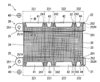
- FIG. 1 is a plan view of an electromagnetic shielding tool 10 according to the first embodiment.
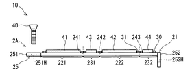
- FIG. 2 is a front view of the electromagnetic shielding tool 10 according to the first embodiment.
- FIG. 3 is a cross-sectional view of a joining portion (crimping portion) between the long portion 221 and the metal sheet 30 in the electromagnetic shielding tool 10.
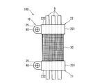
- FIG. 4 is a plan view of the wire harness 100 according to the first embodiment.
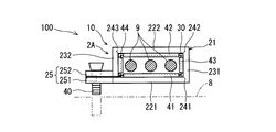
- FIG. 5 is a front view of the wire harness 100 according to the first embodiment.
- the electromagnetic shielding tool 10 shown in FIGS. 1 and 2 is in a deployed state, and the electromagnetic shielding tool 10 shown in FIGS. 4 and 5 is in a state of being held in an annular shape.
- the electromagnetic shield 10 is a component that is attached to an electric wire of a wire harness mounted on a vehicle and shields noise electromagnetic waves with a conductive metal sheet (metal sheet 30) surrounding the electric wire.
- the electromagnetic shielding tool 10 includes a pair of bracket main body portions 21 and 22, a metal sheet 30, and a pair of screws 40 that are fixing tools.
- the metal sheet 30 is joined to each of the bracket body parts 21 and 22.
- the pair of screws 40 is a fixture for holding each of the bracket main body portions 21 and 22 in an annular shape.
- the pair of bracket main bodies 21 and 22 and the pair of screws 40 constitute a pair of brackets 2A and 2B. That is, the electromagnetic shielding tool 10 includes a pair of brackets 2A and 2B.
- the bracket 2A is fixed to a metal casing (housing 8) of a device to which one end of the electric wire 9 is connected, and the other end of the electric wire 9 is connected to the bracket 2B. It is fixed to the casing of the equipment to be used.
- the wire harness 100 includes a plurality of (here, three) electric wires 9 and an electromagnetic shield 10 that collectively covers the periphery of the plurality of electric wires 9.
- the wire harness 100 includes a cylindrical electromagnetic shield 10 and a plurality of electric wires 9 inserted through the cylindrical electromagnetic shield 10. It is assumed that the electromagnetic shield 10 of the wire harness 100 covers only one electric wire 9. Moreover, the electromagnetic shielding tool 10 is also assumed to cover a number of wires (3, 6, 9,...) That is a multiple of 3.
- the electric wire 9 is an insulated wire composed of a core wire made of a conductive material and an insulating coating made of an insulating material covering the periphery of the core wire.
- a metal terminal (not shown) is connected to the core wire at the end of the electric wire 9.
- the electric wire 9 may be hold
- Such an electric wire holding member is considered to be a thermoplastic resin member molded by insert molding using the electric wire 9 as an insert portion.
- the metal sheet 30 included in the electromagnetic shielding tool 10 is a sheet-like member that is a metal yarn fabric.
- the metal sheet 30 is, for example, a metal cloth having a stitch structure formed by weaving a metal thread mainly composed of a conductive metal (copper or the like) in the longitudinal direction and the transverse direction.
- the metal sheet 30 has the softness
- the electromagnetic shielding tool 10 may include a metal foil as the metal sheet 30 instead of the metal cloth.
- the metal sheet 30 has conductivity and flexibility.
- first outer edge part 31 a first outer edge part 31, a second outer edge part 32, a third outer edge part 33, and a fourth outer edge part 34, respectively.
- the first outer edge portion 31 is a portion of the four outer edges of the metal sheet 30 that occupies a certain range from the outer edge forming one end in the longitudinal direction (axial direction) of the electric wire 9 to be attached to the inside.
- the second outer edge portion 32 is a portion occupying a certain range inward from the outer edge on the opposite side to the first outer edge portion 31 among the four outer edges of the metal sheet 30.
- the third outer edge portion 33 and the fourth outer edge portion 34 are outer edge portions other than the first outer edge portion 31 and the second outer edge portion 32 among the outer edge portions of the metal sheet 30.
- the third outer edge portion 33 and the fourth outer edge portion 34 are outer edge portions forming both ends in the circumferential direction surrounding the periphery of the electric wire 9 in the metal sheet 30.
- the metal sheet 30 is joined to the bracket body 21 at the first outer edge 31.
- the metal sheet 30 is joined to the bracket body 22 at the second outer edge portion 32.
- the metal sheet 30 is electrically connected to the casing 8 of another device via the pair of brackets 2A and 2B, and serves as casing grounding.
- Bracket> The bracket body parts 21 and 22 are plate-like members formed of a conductive material.
- the bracket main body portions 21 and 22 are formed into an annular shape shown in FIGS. 4 and 5 by bending.
- the bracket main bodies 21 and 22 are metal members such as copper alloy, iron or stainless steel, for example, and a plating layer is appropriately formed on the surface.
- the bracket main bodies 21 and 22 are members that are fixed to the metal housing 8 and relay electrical connection between the metal sheet 30 and the housing 8.
- bracket body parts 21 and 22 are mirror images, the structure of the bracket body part 21 will be described below.
- the bracket main body portion 21 includes a plate-like base portion 201 along the first outer edge portion 31 of the metal sheet 30.
- the base body 201 is valley-folded at three places (bending parts 241, 242, 243), whereby the bracket main body part 21 is formed in an annular shape (substantially rectangular tube shape) (see FIG. 5).
- the base 201 is divided into a pair of long portions 221, 222 and a pair of short portions 231, 232 by three bent portions 241, 242, 243.
- the pair of long portions 221 and 222 are portions spanned across the plurality of electric wires 9 to be shielded.
- the pair of long portions 221 and 222 have substantially the same length.
- the pair of long portions 221 and 222 face each other so as to extend in parallel to each other.
- the shape and length of the pair of long portions 221 and 222 are not limited to this, and differ depending on the arrangement state of the plurality of electric wires 9 or the shape of the electric wire holding member.
- the long portions 221 and 222 may have a non-linear shape such as a portion that bends in an arc.
- the pair of long portions 221 and 222 are joined to the metal sheet 30 in a state of being arranged in series along the first outer edge portion 31.
- the metal sheet 30 and the pair of long portions 221 and 222 are joined by, for example, pressure bonding, welding, or both.
- bonding by pressure bonding is adopted as will be described later.
- the pair of long portions 221 and 222 of the bracket body portion 21 are joined to the first outer edge portion 31, and the pair of long portions 221 and 222 of the bracket body portion 22 are joined to the second outer edge portion 32. Yes.
- the pair of long portions 221 and 222 includes plate-like folded portions 41 and 42 each having one end connected to the base 201.
- the metal sheet 30 is clamped by the base part 201 and the folding
- the pair of short portions 231 and 232 are joined to the metal sheet 30 in a state of being arranged in series along the first outer edge portion 31.
- Each of the pair of short portions 231 and 232 is shorter than each of the pair of long portions 221 and 222.
- One end of the short part 231 is connected to the other end of the long part 221 through the bending part 241, and the other end of the short part 231 is connected to one end of the long part 222 through the bending part 242.
- One end of the short part 232 is connected to the other end of the long part 222 via the bent part 243.
- the pair of short portions 231 and 232 have substantially the same length.
- the pair of short parts 231 and 232 face each other so as to extend in parallel to each other.
- the shape and length of the pair of short portions 231 and 232 are not limited to this, and differ depending on the arrangement state of the plurality of electric wires 9 or the shape of the electric wire holding member.
- the pair of short portions 231 and 232 include plate-like folded portions 43 and 44 each having one end connected to the base 201.
- the metal sheet 30 is sandwiched between the base 201 and the folded portions 43 and 44 by being crimped to the base 201 with the folded portions 43 and 44 sandwiching the metal sheet 30 therebetween.
- the metal sheet 30 When joining the metal sheet 30 to the pair of brackets 2A and 2B by welding, the metal sheet 30 may be broken during welding. Therefore, it is desirable to join the metal sheet 30 by crimping the folded portions 41 to 44.
- the three bent portions 241 to 243 are portions that are bent in a valley shape when the bracket main body portions 21 and 22 are formed into an annular shape. Note that it is not essential to bend the bent portions 241 to 243 so that the bent portions 241 to 243 can be bent.
- the bent portions 241 to 243 are positioned so as not to overlap the folded portions 41 to 44.
- the bent portions 241, 242, and 243 are non-joined portions that are not joined to the metal sheet 30. Since the thickness of the bent portions 241 to 243 is the thickness of only the base portion 201, bending at these portions is easier than the joining portion (the portion overlapping the bent portions 241 to 243 of the base portion 201).
- joining means attaching or fixing an object to another object by means such as crimping or welding.
- the non-joined portion is a portion where the metal sheet 30 can be easily separated from the bracket main body portions 21 and 22.
- the bent portions 241 to 243 As non-joined portions, it is possible to prevent the bent portions 241 to 243 from exerting stress on the metal sheet 30 when being bent at these portions. Therefore, the metal sheet 30 can be suitably held in an annular shape by the bent bracket body portions 21 and 22.
- joining with the bracket main-body parts 21 and 22 and the metal sheet 30 may be performed by welding.
- the folding portions 41 to 44 can be omitted.
- the bent portions 241 to 243 be non-joined portions that are not welded. Accordingly, it is possible to prevent the bending portions 241 to 243 from applying stress to the metal sheet 30 when the bending portions 241 to 243 are bent. For this reason, for example, by bending the bracket body portions 21 and 22, the welded portion of the metal sheet 30 (the portion of the metal sheet 30 bonded by melting and solidifying the metal sheet 30 or the bracket body portions 21 and 22). ), It is possible to suppress the occurrence of damage such as peeling or tearing.
- the connecting portion 25 includes connecting pieces 251 and 252 formed in a plate shape connected to both ends of the base 201.
- the connecting piece 251 is connected to one end side of the long portion 221 in the base portion 201, and the connecting piece 252 is connected to the other end side of the short portion 232 in the base portion 201.
- the connecting piece 251 is a plate-like portion extending in parallel with the main surface of the base 201 (the widest surface and the surface joined to the metal sheet 30), and the connecting piece 252. Is a plate-like portion extending in a direction perpendicular to the main surface of the base 201. That is, in the bracket main body portions 21 and 22 in the unfolded state, the connecting pieces 251 and 252 are plate-like portions that are orthogonal to each other.
- the connecting piece 252 becomes substantially parallel to the connecting piece 251 and overlapped as shown in FIG. Thereby, the bracket main body portions 21 and 22 are formed in an annular shape, and the first outer edge portion 31 and the second outer edge portion 32 of the metal sheet 30 are formed in an annular shape.
- connection pieces 251 and 252 are formed with screw holes 251H and 252H which are through holes.
- the screw holes 251H and 252H are vertically overlapped by overlapping the connecting pieces 251 and 252.
- the connecting pieces 251 and 252 are connected by attaching the screw 40 to the screw holes 251H and 252H.
- the connecting portion 25 including the connecting pieces 251 and 252 and the screw 40 are an example of a connecting portion.
- the connecting portion is not limited to the configuration of the connecting pieces 251 and 252 and the screw 40, and can be appropriately changed in design.
- the connecting portion 25 extends in parallel with the base portion 201, and the connecting portion 25 may extend in a direction inclined with respect to the base portion 201.
- brackets 2 ⁇ / b> A and 2 ⁇ / b> B are held in an annular shape, the metal sheet 30 joined to the bracket main body 21 and the bracket main body 22 is held in a cylindrical shape surrounding the wire 9.
- the connecting piece 252 of the connecting portion 25 is a portion extending outward from the other end of the short portion 232 (second short portion).
- the other end of the short part 232 (that is, the bent part connected to the connecting piece 252) is closer to the long part 221 (first long part) than the long part 222 (second long part). It is unevenly distributed at a close position.
- the region (joint surface) of the short portion 232 to be bonded to the metal sheet 30 can be made as long as possible. Thereby, the folding
- the short portion 231 that connects them is also joined to the metal sheet 30, so the pair of brackets 2 ⁇ / b> A and 2 ⁇ / b> B are firmly attached to the metal sheet 30. it can.
- the short part 232 that connects the pair of long parts 221 and 222 via the connecting part 25 is also joined to the metal sheet 30, the pair of brackets 2A and 2B can be firmly attached to the metal sheet 30.
- the metal sheet 30 is firmly attached to the pair of brackets 2A and 2B, so that the shape of the metal sheet 30 can be prevented from collapsing. Thereby, it can suppress that the noise absorption performance of the electromagnetic shielding tool 10 falls.
- each of the bracket main body portions 21 and 22 is configured by one plate-like member.
- FIG. 6 is a front view of a wire harness 100A provided with the electromagnetic shielding tool 10A according to the second embodiment.
- the electromagnetic shielding tool 10A includes a bracket 2C having a bracket body 21A.
- the bracket body 21A has a configuration similar to that of the bracket body 21, but a portion corresponding to the short portion 232 is a short portion 232a (second short portion).
- the other end side of the short part 232a is connected to the long part 221 through the connecting part 25 and the short part 232b (third short part).
- the short part 232 b is connected to one end side of the long part 221 through the bent part 244.
- the other end of the short portion 232 a is set at a substantially central position of the long portion 221 and the long portion 222, and is shorter than the short portion 232, and is joined to the metal sheet 30.
- the bent portion is omitted.
- the bracket 2C is inferior to the bracket 2A in terms of the joining force because the bracket 2C is not joined to the metal sheet 30 by the short portion 232a.
- the bracket 2C can be firmly attached to the metal sheet 30.
Landscapes
- Engineering & Computer Science (AREA)
- Mechanical Engineering (AREA)
- Architecture (AREA)
- Civil Engineering (AREA)
- Structural Engineering (AREA)
- Microelectronics & Electronic Packaging (AREA)
- Shielding Devices Or Components To Electric Or Magnetic Fields (AREA)
- Details Of Indoor Wiring (AREA)
- Insulated Conductors (AREA)
Priority Applications (2)
| Application Number | Priority Date | Filing Date | Title |
|---|---|---|---|
| CN201780024805.1A CN109076724B (zh) | 2016-04-28 | 2017-04-21 | 电磁屏蔽件以及线束 |
| US16/095,824 US10595449B2 (en) | 2016-04-28 | 2017-04-21 | Electromagnetic shielding device and wire harness |
Applications Claiming Priority (2)
| Application Number | Priority Date | Filing Date | Title |
|---|---|---|---|
| JP2016-090490 | 2016-04-28 | ||
| JP2016090490A JP6614017B2 (ja) | 2016-04-28 | 2016-04-28 | 電磁シールド具及びワイヤーハーネス |
Publications (1)
| Publication Number | Publication Date |
|---|---|
| WO2017188148A1 true WO2017188148A1 (ja) | 2017-11-02 |
Family
ID=60161510
Family Applications (1)
| Application Number | Title | Priority Date | Filing Date |
|---|---|---|---|
| PCT/JP2017/016033 Ceased WO2017188148A1 (ja) | 2016-04-28 | 2017-04-21 | 電磁シールド具及びワイヤーハーネス |
Country Status (4)
| Country | Link |
|---|---|
| US (1) | US10595449B2 (cg-RX-API-DMAC7.html) |
| JP (1) | JP6614017B2 (cg-RX-API-DMAC7.html) |
| CN (1) | CN109076724B (cg-RX-API-DMAC7.html) |
| WO (1) | WO2017188148A1 (cg-RX-API-DMAC7.html) |
Cited By (1)
| Publication number | Priority date | Publication date | Assignee | Title |
|---|---|---|---|---|
| US20220176898A1 (en) * | 2019-03-29 | 2022-06-09 | Autonetworks Technologies, Ltd. | Wiring module |
Citations (3)
| Publication number | Priority date | Publication date | Assignee | Title |
|---|---|---|---|---|
| JP2012222888A (ja) * | 2011-04-05 | 2012-11-12 | Sumitomo Wiring Syst Ltd | ワイヤハーネスの配索構造 |
| JP2014123623A (ja) * | 2012-12-20 | 2014-07-03 | Auto Network Gijutsu Kenkyusho:Kk | 電磁シールド部材およびワイヤーハーネス |
| JP2015153591A (ja) * | 2014-02-13 | 2015-08-24 | 住友電気工業株式会社 | 端子台 |
Family Cites Families (9)
| Publication number | Priority date | Publication date | Assignee | Title |
|---|---|---|---|---|
| JPH0755027Y2 (ja) * | 1989-09-14 | 1995-12-18 | 富士通株式会社 | ケーブルクランプ |
| JP3713528B2 (ja) * | 2001-12-26 | 2005-11-09 | 株式会社オートネットワーク技術研究所 | 機器取付け用ワイヤーハーネス |
| JP2009048952A (ja) * | 2007-08-22 | 2009-03-05 | Auto Network Gijutsu Kenkyusho:Kk | シールド導電体 |
| JP2009054363A (ja) * | 2007-08-24 | 2009-03-12 | Yazaki Corp | 導体シート及びこの導体シートを備えたシールドハーネス |
| JP5293644B2 (ja) * | 2010-03-02 | 2013-09-18 | 住友電装株式会社 | ワイヤハーネスの配索構造 |
| CN102884591B (zh) * | 2010-08-31 | 2015-08-12 | 3M创新有限公司 | 高密度屏蔽电缆和其他屏蔽电缆、系统以及方法 |
| WO2013074149A1 (en) * | 2011-11-14 | 2013-05-23 | 3M Innovative Properties Company | Wide pitch differential pair cable |
| JP5942703B2 (ja) * | 2012-01-23 | 2016-06-29 | 株式会社オートネットワーク技術研究所 | 電磁シールド具及びワイヤハーネス |
| JP5772772B2 (ja) * | 2012-09-11 | 2015-09-02 | 株式会社オートネットワーク技術研究所 | 電磁シールド具及びワイヤハーネス |
-
2016
- 2016-04-28 JP JP2016090490A patent/JP6614017B2/ja active Active
-
2017
- 2017-04-21 WO PCT/JP2017/016033 patent/WO2017188148A1/ja not_active Ceased
- 2017-04-21 CN CN201780024805.1A patent/CN109076724B/zh active Active
- 2017-04-21 US US16/095,824 patent/US10595449B2/en active Active
Patent Citations (3)
| Publication number | Priority date | Publication date | Assignee | Title |
|---|---|---|---|---|
| JP2012222888A (ja) * | 2011-04-05 | 2012-11-12 | Sumitomo Wiring Syst Ltd | ワイヤハーネスの配索構造 |
| JP2014123623A (ja) * | 2012-12-20 | 2014-07-03 | Auto Network Gijutsu Kenkyusho:Kk | 電磁シールド部材およびワイヤーハーネス |
| JP2015153591A (ja) * | 2014-02-13 | 2015-08-24 | 住友電気工業株式会社 | 端子台 |
Cited By (2)
| Publication number | Priority date | Publication date | Assignee | Title |
|---|---|---|---|---|
| US20220176898A1 (en) * | 2019-03-29 | 2022-06-09 | Autonetworks Technologies, Ltd. | Wiring module |
| US11878640B2 (en) * | 2019-03-29 | 2024-01-23 | Autonetworks Technologies, Ltd. | Wiring module |
Also Published As
| Publication number | Publication date |
|---|---|
| JP2017199839A (ja) | 2017-11-02 |
| CN109076724A (zh) | 2018-12-21 |
| JP6614017B2 (ja) | 2019-12-04 |
| US10595449B2 (en) | 2020-03-17 |
| CN109076724B (zh) | 2020-02-14 |
| US20190320559A1 (en) | 2019-10-17 |
Similar Documents
| Publication | Publication Date | Title |
|---|---|---|
| CN104067468B (zh) | 电磁屏蔽件以及线束 | |
| JP6394524B2 (ja) | 電磁シールド部材及び電磁シールド部材付配線装置 | |
| JP6979957B2 (ja) | 電磁シールド構造およびワイヤハーネス | |
| CN111210927B (zh) | 导电部件 | |
| CN107533887B (zh) | 导电部件 | |
| JP6377694B2 (ja) | 端子金具固定構造およびワイヤハーネス | |
| CN110506375B (zh) | 线束 | |
| JP6774627B2 (ja) | 電線の接合構造及びワイヤハーネス | |
| JP6614017B2 (ja) | 電磁シールド具及びワイヤーハーネス | |
| JP6156173B2 (ja) | 電磁シールド部品 | |
| JP2016100200A (ja) | シールド電線及びその製造方法 | |
| JP6409672B2 (ja) | 電線モジュール | |
| WO2016080522A1 (ja) | 導電部材及び電磁シールド具 | |
| JP2006269666A (ja) | シールド構造体 | |
| JP2022138798A (ja) | ワイヤーハーネスおよび接地構造体 | |
| WO2017175699A1 (ja) | 導体の接続構造およびワイヤハーネス | |
| JP2007012515A (ja) | シールド導電体 | |
| JP6556512B2 (ja) | ワイヤハーネス | |
| JP5772698B2 (ja) | 電磁シールド具及びワイヤハーネス | |
| JP6326271B2 (ja) | 電線のシールド構造 | |
| JP2016072583A (ja) | 電磁シールド部材 | |
| JP5835118B2 (ja) | 固定具 | |
| JP2010055821A (ja) | 導電体及び導電体の製造方法 | |
| JP2017126403A (ja) | シールド電線及びシールド電線の製造方法 |
Legal Events
| Date | Code | Title | Description |
|---|---|---|---|
| NENP | Non-entry into the national phase |
Ref country code: DE |
|
| 121 | Ep: the epo has been informed by wipo that ep was designated in this application |
Ref document number: 17789431 Country of ref document: EP Kind code of ref document: A1 |
|
| 122 | Ep: pct application non-entry in european phase |
Ref document number: 17789431 Country of ref document: EP Kind code of ref document: A1 |