WO2017187967A1 - 光学センサ - Google Patents
光学センサ Download PDFInfo
- Publication number
- WO2017187967A1 WO2017187967A1 PCT/JP2017/014839 JP2017014839W WO2017187967A1 WO 2017187967 A1 WO2017187967 A1 WO 2017187967A1 JP 2017014839 W JP2017014839 W JP 2017014839W WO 2017187967 A1 WO2017187967 A1 WO 2017187967A1
- Authority
- WO
- WIPO (PCT)
- Prior art keywords
- space
- emitting element
- light
- light emitting
- receiving element
- Prior art date
- Legal status (The legal status is an assumption and is not a legal conclusion. Google has not performed a legal analysis and makes no representation as to the accuracy of the status listed.)
- Ceased
Links
Images








Classifications
-
- G—PHYSICS
- G01—MEASURING; TESTING
- G01N—INVESTIGATING OR ANALYSING MATERIALS BY DETERMINING THEIR CHEMICAL OR PHYSICAL PROPERTIES
- G01N21/00—Investigating or analysing materials by the use of optical means, i.e. using sub-millimetre waves, infrared, visible or ultraviolet light
- G01N21/17—Systems in which incident light is modified in accordance with the properties of the material investigated
- G01N21/59—Transmissivity
-
- G—PHYSICS
- G01—MEASURING; TESTING
- G01N—INVESTIGATING OR ANALYSING MATERIALS BY DETERMINING THEIR CHEMICAL OR PHYSICAL PROPERTIES
- G01N33/00—Investigating or analysing materials by specific methods not covered by groups G01N1/00 - G01N31/00
- G01N33/26—Oils; Viscous liquids; Paints; Inks
- G01N33/28—Oils, i.e. hydrocarbon liquids
- G01N33/2888—Lubricating oil characteristics, e.g. deterioration
-
- H—ELECTRICITY
- H10—SEMICONDUCTOR DEVICES; ELECTRIC SOLID-STATE DEVICES NOT OTHERWISE PROVIDED FOR
- H10N—ELECTRIC SOLID-STATE DEVICES NOT OTHERWISE PROVIDED FOR
- H10N10/00—Thermoelectric devices comprising a junction of dissimilar materials, i.e. devices exhibiting Seebeck or Peltier effects
- H10N10/10—Thermoelectric devices comprising a junction of dissimilar materials, i.e. devices exhibiting Seebeck or Peltier effects operating with only the Peltier or Seebeck effects
- H10N10/13—Thermoelectric devices comprising a junction of dissimilar materials, i.e. devices exhibiting Seebeck or Peltier effects operating with only the Peltier or Seebeck effects characterised by the heat-exchanging means at the junction
-
- H—ELECTRICITY
- H10—SEMICONDUCTOR DEVICES; ELECTRIC SOLID-STATE DEVICES NOT OTHERWISE PROVIDED FOR
- H10N—ELECTRIC SOLID-STATE DEVICES NOT OTHERWISE PROVIDED FOR
- H10N10/00—Thermoelectric devices comprising a junction of dissimilar materials, i.e. devices exhibiting Seebeck or Peltier effects
- H10N10/10—Thermoelectric devices comprising a junction of dissimilar materials, i.e. devices exhibiting Seebeck or Peltier effects operating with only the Peltier or Seebeck effects
- H10N10/17—Thermoelectric devices comprising a junction of dissimilar materials, i.e. devices exhibiting Seebeck or Peltier effects operating with only the Peltier or Seebeck effects characterised by the structure or configuration of the cell or thermocouple forming the device
Definitions
- the present invention relates to an optical sensor.
- an optical sensor for detecting deterioration of lubricating oil in a machine is a first space between a light emitting element that emits light and a gap forming member in which a gap for oil that is a gap for oil to enter is formed.
- the space between the light receiving element that detects light and the gap forming member is the second space, and on the surface where the gap forming member is bonded to the light emitting element, the light receiving element and the support member that supports the gap forming member,
- a configuration is disclosed in which grooves are formed around the opening in the first space and the opening in the second space (see, for example, Japanese Patent No. 5839436 (Patent Document 1)).
- Patent Document 1 describes that an annular groove is formed in order to prevent the adhesive that fixes the gap forming member to the support member from entering the first space and the second space. . If an excessive amount of adhesive is applied in order to securely fix the gap forming member to the support member, the adhesive may protrude into the first space or the second space. The first space and the second space form an optical path from the light emitting element to the light receiving element. Therefore, there is a possibility that the adhesive that protrudes into the first space or the second space interferes with the optical path and obstructs light, thereby reducing the detection accuracy of the optical sensor. On the other hand, when the amount of the adhesive is insufficient, there is a possibility that the fixing strength of the gap forming member to the support member is insufficient, or that the lubricating oil leaks between the gap forming member and the support member. .
- An object of the present invention is to provide an optical sensor that can reliably support a member that forms an optical path without interfering with the optical path from the light emitting element to the light receiving element.
- the optical sensor of the present invention includes a light emitting element that emits light and a light receiving element that receives light emitted by the light emitting element.
- the optical path from the light emitting element to the light receiving element passes through an oil intrusion space that is a space for oil to enter.
- the optical sensor further includes a substrate on which one or both of the light emitting element and the light receiving element are mounted, a housing member in which a housing space for housing the substrate is formed, and a sealing resin that fills the housing space and seals the substrate And.
- the member that forms the optical path can be reliably supported without interfering with the optical path from the light emitting element to the light receiving element.
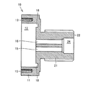
- FIG. 5 is a cross-sectional view of the fixing member taken along the line VV in FIGS.
- FIG. 8 is a cross-sectional view of the holding member taken along line IX-IX in FIG. 7.
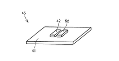
- FIG. 24 is a cross-sectional view of the fixing member taken along line XXIV-XXIV in FIGS. It is a perspective view which shows schematic structure of a light reception / light emitting element module. It is sectional drawing of the state in which the optical sensor based on 2nd embodiment was installed in the machine. It is sectional drawing of the optical sensor based on 3rd embodiment.
- FIG. 1 is a front view of an optical sensor 1 according to the first embodiment.
- the optical sensor 1 is a device that is attached to a machine and detects impurities in the lubricating oil of the machine.
- the machine to which the optical sensor 1 is attached may be, for example, a machine mounted on a work vehicle represented by a mining machine.
- the optical sensor 1 may be attached to, for example, a gear box, a transaxle or a hydraulic system.
- the optical sensor 1 includes a fixing member 10 for fixing the optical sensor 1 to a machine.
- the fixing member 10 has a bolt shape and has a head portion 11 and a screw portion 21.
- the head 11 has a regular hexagonal columnar outer shape.
- a screw thread is formed on the outer peripheral surface of the screw portion 21.
- the screw portion 21 has a tip surface 22.
- the screw portion 21 is formed with a groove in which a part of the front end surface 22 is recessed. This groove constitutes an oil intrusion space 23 for the lubricating oil to enter.
- the optical sensor 1 also includes a lid member 60 disposed away from the head 11 of the fixing member 10, a heat insulating member 70 disposed between the fixing member 10 and the lid member 60, and the fixing member 10 and the lid member. And a plurality of bolts 80 that are integrally connected to each other.
- the fixing member 10 and the lid member 60 are made of a material having high thermal conductivity such as metal.
- the fixing member 10 and the lid member 60 may be formed of, for example, a steel material or an aluminum alloy.
- the heat insulating member 70 is formed of a material having low thermal conductivity such as a resin in order to suppress heat transfer between the fixing member 10 and the lid member 60.
- the heat insulating member 70 is formed of a material having a lower thermal conductivity than that of the fixing member 10 and the lid member 60.
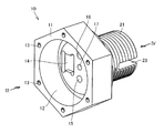
- FIG. 2 is a perspective view of the fixing member 10 shown in FIG.
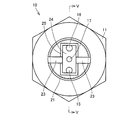
- FIG. 3 is an external view of the fixing member 10 as viewed from the direction of arrow III in FIG. 4 is an external view of the fixing member 10 as viewed from the direction of arrow IV in FIG.
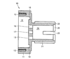
- FIG. 5 is a cross-sectional view of the fixing member 10 taken along line VV in FIGS.
- the head portion 11 and the screw portion 21 of the fixing member 10 are formed hollow.
- a hollow housing space 12 is formed inside the head 11.
- a hollow housing space 24 is formed inside the screw portion 21.
- An annular groove 18 in which the bottom surface is recessed in an annular shape and a recess 14 in which the bottom surface is recessed in a substantially rectangular shape are formed on the bottom surface of the accommodation space 12.
- a plurality of bottomed screw holes 13 are also formed in the head 11.
- the screw holes 13 are formed near the apexes of a regular hexagon when the head 11 is viewed in plan.
- the screw holes 13 are formed in the same number as the bolts 80 shown in FIG.
- the fixing member 10 and the lid member 60 are integrated with each other by fastening the bolt 80 to each screw hole 13.
- the through hole includes wiring through holes 15 and 16 through which a wiring to be described later passes, and a fixing hole 17 for fixing a holding member to be described later.
- the fixing hole 17 is formed at the center position of the fixing member 10 shown in FIGS.
- the wiring through holes 15 and 16 are formed at positions spaced equidistant from the center of the fixing member 10.
- the wiring through holes 15 and 16 and the fixing hole 17 are formed in a straight line as shown in FIGS.
- the above-described arrangement of the wiring through holes 15 and 16 and the fixing hole 17 is an example, and their positions are changed depending on the thickness and / or eccentricity of the element.
- the screw portion 21 is formed with an enlarged space 25 that is a hollow space.
- the enlarged diameter space 25 is open to the distal end surface 22 of the screw portion 21.
- the accommodation space 24 opens to the distal end surface 22 of the screw portion 21 through the enlarged diameter space 25.
- the enlarged space 25 communicates with the accommodation space 24.
- the enlarged space 25 has an inner diameter larger than the inner diameter of the accommodation space 24.
- the groove forming the oil intrusion space 23 formed in the screw portion 21 is divided into two by an accommodation space 24 and a diameter expansion space 25.
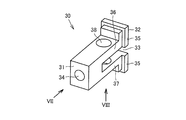
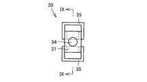
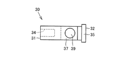
- FIG. 6 is a perspective view of the holding member 30.
- FIG. 7 is an external view of the holding member 30 as seen from the direction of arrow VII in FIG.
- FIG. 8 is an external view of the holding member 30 as seen from the direction of the arrow VIII in FIG.
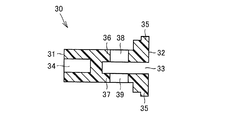
- FIG. 9 is a cross-sectional view of the holding member 30 along the line IX-IX in FIG.
- the holding member 30 has a distal end surface 31 and a proximal end surface 32.
- the distal end surface 31 and the proximal end surface 32 each have a planar shape.
- the distal end surface 31 and the proximal end surface 32 are provided in parallel.
- the front end surface 31 is formed in a rectangular shape.
- a bottomed hole 34 is formed in the central portion of the distal end surface 31.
- An insert nut is inserted into the hole 34.
- the base end face 32 may be disk-shaped, and in this case, the accommodation space 24 formed in the fixing member 10 is cylindrical.
- the passing length of the distal end surface 31 is smaller than the passing length of the proximal end surface 32.
- the holding member 30 has a larger diameter at the proximal end surface 32 than at the distal end surface 31.
- the holding member 30 has an enlarged diameter portion 35 on the proximal end surface 32.
- the shape of the outer periphery of the enlarged diameter portion 35 is substantially the same as the shape of the inner periphery of the enlarged diameter space 25 of the fixing member 10.
- the outer peripheral shape of the distal end surface 31 is smaller than the inner peripheral shape of the accommodation space 24 of the fixing member 10.
- the holding member 30 is formed with a groove in which a part of the base end face 32 is recessed.
- the base end face 32 has a shape in which a rectangular shape is divided into two by the groove.
- the groove extends in the short-side direction of a rectangle that forms the outer edge shape of the base end face 32.
- the groove formed in the base end face 32 constitutes an oil intrusion space 33 for the lubricating oil to enter.
- the width of the oil entry space 33 of the holding member 30 (the passing dimension of the oil entry space 33 in the vertical direction in FIG. 9) is the width of the oil entry space 23 of the fixing member 10 (the oil in the vertical direction in FIG. 5). It is equal to the passing dimension of the intrusion space 23).
- the holding member 30 in the vicinity of the base end face 32 is divided into a light receiving element support portion 36 and a light emitting element support portion 37 by an oil intrusion space 33.
- the light receiving element support portion 36 is formed with a through-hole penetrating the light receiving element support portion 36. This through hole constitutes a light receiving element receiving hole 38 for receiving the light receiving element.
- the light emitting element support portion 37 is formed with a through hole penetrating the light emitting element support portion 37.
- the through hole constitutes a light emitting element accommodation hole 39 for accommodating the light emitting element.
- the holding member 30 may be a resin molded product.
- the holding member 30 may be made of a metal material such as an aluminum alloy.
- FIG. 10 is a perspective view showing a state in which the holding member 30 is assembled to the fixing member 10.
- FIG. 11 is a perspective view of the state in which the holding member 30 is assembled to the fixing member 10 as seen from different angles.
- the holding member 30 has a shape in which the proximal end surface 32 has a larger outer diameter than the distal end surface 31.
- the expanded diameter portion 35 is substantially engaged with the expanded diameter space 25 as shown in FIGS. .
- the distal end surface 22 of the fixing member 10 and the proximal end surface 32 of the holding member 30 are substantially on the same plane.
- the oil intrusion space 23 formed in the fixing member 10 and the oil intrusion space 33 formed in the holding member 30 have the same width.
- the inner wall surface of the oil ingress space 23 and the inner wall surface of the oil ingress space 33 are on substantially the same plane.
- the outer peripheral shape of the holding member 30 in the vicinity of the front end surface 31 is smaller than the inner peripheral shape of the accommodation space 24. Therefore, as shown in FIGS. 10 and 11, in a state where the holding member 30 is accommodated in the accommodation space 24, a part of the accommodation space 24 still exists as a hollow space.
- the housing space 24 is partitioned by the holding member 30 to form two hollow spaces. One hollow space communicates with the wiring through hole 15, and the other hollow space communicates with the wiring through hole 16. One hollow space communicates with the accommodation space 12 through the wiring through hole 15. The other hollow space communicates with the accommodation space 12 through the wiring through hole 16.
- the hole 34 formed in the holding member 30 communicates with the fixing hole 17 of the fixing member 10.
- the hole 34 communicates with the accommodation space 12 through the fixing hole 17.
- FIG. 12 is a schematic diagram showing a schematic configuration of the light receiving element module 40.
- the light receiving element module 40 has a substrate 41.
- a light receiving element 42 is mounted on the main surface of the substrate 41.
- the light receiving element 42 is an electronic component that receives light emitted from the light emitting element 52, and is, for example, a photodiode.
- a wiring 43 is connected to the substrate 41. The amount of light received by the light receiving element 42 is output to the outside via the wiring 43.
- FIG. 13 is a schematic diagram showing a schematic lattice of the light emitting element module 50.
- the light emitting element module 50 has a substrate 51.
- a light emitting element 52 is mounted on the main surface of the substrate 51.
- the light emitting element 52 is an electronic component that emits monochromatic light, for example.
- the light emitting element 52 is, for example, a red LED (Light Emitting Diode).
- Wirings 53 and 54 are connected to the substrate 51. Power is supplied to the light emitting element 52 via the wirings 53 and 54, and a signal instructing the presence or absence of light emission and the light emission amount is input to the light emitting element 52.
- the light emitting element 52 may be a white LED that emits white light, and in this case, the light receiving element 42 may be an RGB sensor that detects the color of the received light.
- FIG. 14 is a partial cross-sectional view showing a state where the light receiving element module 40 and the light emitting element module 50 are assembled to the holding member 30.
- the light receiving element 42 is accommodated in the light receiving element accommodation hole 38 formed in the light receiving element support portion 36 of the holding member 30.
- the light emitting element 52 is accommodated in the light emitting element accommodation hole 39 formed in the light emitting element support portion 37 of the holding member 30.
- the light receiving element 42 and the light emitting element 52 face each other with the oil entry space 33 interposed therebetween.
- the light receiving element 42 and the light emitting element 52 are exposed in the oil penetration space 33.
- the light receiving element 42 and the light emitting element 52 have oil tightness (or air tightness), so that the lubricating oil in the oil intrusion space 33 is prevented from entering the light receiving element 42 and the light emitting element 52. Yes.
- the substrate 41 on which the light receiving element 42 is mounted and the substrate 51 on which the light emitting element 52 is mounted extend toward the distal end surface 31 along the outer surface of the holding member 30.
- the wiring 43 and the wirings 53 and 54 further extend beyond the distal end surface 31.
- the wiring 43 extends through the wiring through hole 16 to the accommodation space 12.
- the wirings 53 and 54 pass through the wiring through hole 15 and extend to the accommodation space 12.
- FIG. 15 is a perspective view of the heat insulating member 70.
- the heat insulating member 70 has a hollow cylindrical shape.
- the heat insulating member 70 may have a hollow prismatic shape.
- the heat insulating member 70 has one end 71 and the other end 72.
- a hollow housing space 73 is formed inside the heat insulating member 70.
- FIG. 16 is a plan view of the lid member 60.
- FIG. 16 shows the lid member 60 in a state where the bolt 80 (FIG. 1) is not attached as viewed from the top to the bottom in FIG. 1.
- the lid member 60 in plan view has a regular hexagonal outer shape.
- the lid member 60 has a substantially flat shape, and has a first surface 61 and a second surface 62 opposite to the first surface 61 (not shown in FIG. 16).
- the lid member 60 is formed with a plurality of depressions 63 in which the first surface 61 is recessed at each vertex of the hexagon.
- the lid member 60 is also formed with the same number of through-holes 64 as the depression 63 that penetrates the lid member 60 in the thickness direction at the position of the depression 63.
- FIG. 17 is a perspective view showing a schematic configuration of the thermoelectric power generation unit 100.
- the thermoelectric power generation unit 100 is attached to the second surface 62 side of the lid member 60.
- the second surface 62 is formed with an annular groove 65 in which the second surface 62 is recessed in an annular shape.
- An island-shaped portion 66 is formed on the inner peripheral side of the annular groove 65.
- the thermoelectric power generation unit 100 is fixed to the island portion 66.
- the thermoelectric power generation unit 100 mainly includes a thermoelectric power generation module 101, a column member 120, and substrates 131 and 132.
- the column member 120 has a quadrangular columnar shape. The base end of the column member 120 is fixed to the lid member 60.
- the thermoelectric power generation module 101 is attached to the tip of the column member 120.
- the column member 120 may be formed integrally with the lid member 60. Alternatively, the column member 120 may be fixed to the lid member 60 using a heat conductive adhesive.
- the column member 120 is thermally integrated with the lid member 60.
- the column member 120 is formed of a material having high thermal conductivity such as a metal material. Column member 120 may be formed of a material with high heat dissipation, such as an aluminum alloy.
- the thermoelectric power generation module 101 may be attached to the tip of the column member 120 opposite to that in FIG. 17 or may be attached while the column member 120 is divided into two.
- the substrates 131 and 132 are attached to the side surface of the column member 120 via the attachment member 140.
- the substrates 131 and 132 may be attached to the lid member 60.
- the attachment member 140 is, for example, an adhesive sheet-like member, and may be attached to the side surface of the column member 120 and the substrates 131 and 132.
- An electronic component 133 is mounted on the substrate 131.
- An electronic component 134 is mounted on the substrate 132.
- the electronic components mounted on the boards 131 and 132 may constitute a power supply circuit.
- the electronic components mounted on the boards 131 and 132 may constitute a wireless communication circuit that wirelessly transmits the detection result of the light receiving element 42.
- thermoelectric power generation module 101 and the substrate 131 are electrically connected by wirings 111 and 112.
- the substrate 131 and the substrate 132 are electrically connected to each other.
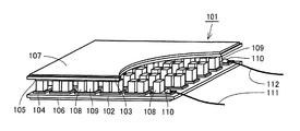
- FIG. 18 is a perspective view showing a schematic configuration of the thermoelectric power generation module 101.
- the thermoelectric power generation module 101 is joined between a heat radiation side substrate 102 and a cooling side substrate 103 so that p-type thermoelectric conversion elements 108 and n-type thermoelectric conversion elements 109 are alternately electrically connected in series. It is configured.
- Al 2 O 3 (aluminum oxide), AlN (aluminum nitride), SiC (silicon carbide), Si 3 N 4 (silicon nitride) and an insulating layer on the outer peripheral surface are used as the heat dissipation side substrate 102 and the cooling side substrate 103. It is made of formed metal or the like.
- thermoelectric conversion elements 108 and n-type thermoelectric conversion elements 109 are mounted on each of the independent heat radiation side electrodes 104. Thereby, the p-type thermoelectric conversion element 108 and the n-type thermoelectric conversion element 109 are electrically connected to the electrode 104 on the heat radiation side.
- a plurality of cooling-side electrodes 105 are formed on the element mounting surface (lower surface) of the cooling-side substrate 103 by plating or the like.
- a pair of p-type thermoelectric conversion elements 108 and n-type thermoelectric conversion elements 109 made of BiTe-based materials are mounted on each of the independent cooling-side electrodes 105.
- the p-type thermoelectric conversion element 108 and the n-type thermoelectric conversion element 109 are electrically connected to the cooling-side electrode 105.
- the position of the heat-dissipating electrode 104 is shifted relative to the cooling electrode 105.
- the plurality of p-type thermoelectric conversion elements 108 and n-type thermoelectric conversion elements 109 joined between the heat radiation side electrode 104 and the cooling side electrode 105 are alternately electrically connected in series. .
- a metallized layer 106 is formed on the back surface (lower surface) of the element mounting surface of the substrate 102 on the heat dissipation side for bonding with a heat dissipation object.
- a metallized layer 107 for bonding with the object to be cooled is also formed on the back surface (upper surface) of the element mounting surface of the substrate 103 on the cooling side.
- wirings 111 and 112 are attached to supply power to the thermoelectric power generation module 101.
- the wiring 111 is attached by solder 110 on the heat radiation side electrode 104 on which only one p-type thermoelectric conversion element 108 is mounted.
- a wiring 112 is attached by solder 110 on the heat radiation side electrode 104 on which only one n-type thermoelectric conversion element 109 is mounted. Thereby, the wirings 111 and 112 are electrically connected to the electrode 104 on the heat radiation side.
- the thermoelectric power generation module 101 converts the temperature difference between the heat dissipation side substrate 102 and the cooling side substrate 103 into electric power.
- the thermoelectric power generation module 101 supplies the generated power to the light emitting element 52, the light receiving element 42, and the electronic circuit mounted on the substrates 131 and 132.
- FIG. 19 is a cross-sectional view showing a state where the optical sensor 1 according to the first embodiment is installed in a machine.
- the machine in which the optical sensor 1 is installed has a housing 200.
- the optical sensor 1 is fixed to the housing 200 by fastening the screw portion 21 of the fixing member 10 to the housing 200.
- the screw portion 21 is fastened to the housing 200 by grasping the hexagonal column-shaped head 11 using a tool (not shown) and rotating the head 11 with respect to the screw hole provided in the housing 200.
- Lubricating oil 201 exists in the internal space of the housing 200.
- a sealing material (not shown) is provided between the outer surface of the housing 200 and the head 11.
- the substrates 41 and 51 are accommodated in the accommodation space 24 that exists as a hollow space in a state where the holding member 30 is assembled to the fixing member 10.
- the housing space 24 is filled with a sealing resin 29.
- the sealing resin 29 covers the entire periphery of the substrates 41 and 51.
- the substrates 41 and 51 accommodated in the accommodation space 24 and a part of the wirings 43, 53 and 54 are sealed with a sealing resin 29.
- the lubricant 201 is prevented from reaching the substrates 41 and 51.
- the light receiving element 42 and the light emitting element 52 have oil tightness. Therefore, it is suppressed that each electronic component which comprises the light receiving element module 40 and the light emitting element module 50 receives the bad influence by the lubricating oil 201.
- the fixing hole 17 of the fixing member 10 is a bolt hole, and the assembly strength of the holding member 30 and the fixing member 10 is improved by rotating a bolt (not shown) and screwing it into an insert nut embedded in the hole 34. Yes.
- the accommodating space 12 (FIGS. 2 and 5) formed inside the head 11 of the fixing member 10, a part of the heat insulating member 70, the thermoelectric power generation module 101 not shown in FIG. A part, a part of the substrate 131, and a part of the substrate 132 (not shown in FIG. 19) are accommodated.
- the fixing member 10 and the lid member 60 are spaced apart in the vertical direction in FIG. 19, and the bottom surface of the accommodation space 12 and the second surface 62 (FIG. 17) face each other.
- the bottom surface of the accommodation space 12 and the second surface 62 are arranged substantially in parallel.
- the heat insulating member 70 and the thermoelectric power generation unit 100 are disposed between the fixing member 10 and the lid member 60.
- the column member 120 and the substrates 131 and 132 are disposed between the fixing member 10 and the lid member 60.
- the heat insulating member 70 thermally separates the fixing member 10 and the lid member 60.
- One end portion 71 (FIG. 15) of the heat insulating member 70 is accommodated in an annular groove 65 (FIG. 17) formed on the second surface 62 of the lid member 60.
- the other end 72 (FIG. 15) of the heat insulating member 70 is accommodated in an annular groove 18 (FIGS. 2 and 5) formed on the bottom surface of the accommodation space 12.
- the heat insulating member 70 is disposed between the lid member 60 and the fixing member 10
- the heat insulating member 70 is not fixed to the lid member 60, and the heat insulating member 70 is fixed to the fixing member 10. There is not.
- One end portion 71 of the heat insulating member 70 is in contact with the lid member 60 in an unfixed state.
- the other end 72 of the heat insulating member 70 is in contact with the fixing member 10 in an unfixed state.
- An O-ring (not shown) is disposed between one end 71 of the heat insulating member 70 and the lid member 60 and between the other end 72 of the heat insulating member 70 and the fixing member 10.
- One end 71 of the heat insulating member 70 is in contact with the lid member 60 via an O-ring.
- the other end 72 of the heat insulating member 70 is in contact with the fixing member 10 via an O-ring.
- the O-ring is provided to seal a hollow housing space 73 formed inside the heat insulating member 70.
- the thermoelectric power generation unit 100 is accommodated in the accommodation space 73.
- the substrate 102 (FIG. 18) on the heat dissipation side of the thermoelectric power generation module 101 is disposed in a recess 14 (FIGS. 2 and 5) formed on the bottom surface of the accommodation space 12.
- the substrate 102 on the heat radiation side is in contact with the bottom surface of the accommodation space 12 via a member such as a carbon sheet that has good thermal conductivity and deforms in the thickness direction.
- the substrate 102 on the heat dissipation side is in contact with the fixing member 10.
- the electrode 104 on the heat dissipation side is in thermal contact with the fixing member 10 via the substrate 102 on the heat dissipation side.
- the cooling-side substrate 103 (FIG. 18) of the thermoelectric power generation module 101 is in contact with the column member 120.
- the substrate 103 on the cooling side is in thermal contact with the lid member 60 via the column member 120.
- the cooling-side electrode 105 is in thermal contact with the lid member 60 via the column member 120 and the cooling-side substrate 103.
- the column member 120 is in contact with the lid member 60 and the substrate 103 on the cooling side of the thermoelectric power generation module 101.
- the fixing member 10 is heated by heat transfer from the lubricating oil 201.
- the lid member 60 is exposed to the atmosphere.
- the fixing member 10 constitutes a high temperature side heat conductor.
- the lid member 60 constitutes a low temperature side heat conductor.
- the heat radiation side electrode 104 constitutes a high temperature side electrode in thermal contact with the high temperature side heat conductor.
- the cooling-side electrode 105 constitutes a low-temperature electrode that is in thermal contact with the low-temperature heat conductor.
- the column member 120 constitutes a heat conduction member that contacts the low-temperature side heat conductor and the thermoelectric power generation module 101.
- the thermoelectric power generation module 101 is provided on the high temperature side with respect to the column member 120.
- the bolt 80 passes through a through hole 64 (FIG. 16) formed in the lid member 60 and is fastened to a screw hole 13 (FIGS. 3 and 5) formed in the head 11 of the fixing member 10.
- the bolt 80 is a separate member different from the heat insulating member 70.
- the fixing member 10 and the lid member 60 are fastened together by bolts 80 with the heat insulating member 70 interposed therebetween.
- the head of the bolt 80 is in contact with the lid member 60.
- the screw portion of the bolt 80 is in contact with the head portion 11 of the fixing member 10.
- the bolt 80 is in contact with both the lid member 60 and the fixing member 10.
- the bolt 80 directly engages with the fixing member 10 and the lid member 60 without engaging with the heat insulating member 70, and fastens the fixing member 10 and the lid member 60 together.
- the bolt 80 constitutes an integrated member that integrates the high temperature side heat conductor and the low temperature side heat conductor.
- the extending direction of the bolt 80 (vertical direction in FIG. 19) is equal to the extending direction of the column member 120 of the thermoelectric power generation unit 100.
- the heat-dissipation-side electrode 104 and the cooling-side electrode 105 of the thermoelectric power generation module 101 are arranged side by side with a space in the vertical direction in FIG. This corresponds to the direction in which the cooling side electrodes 105 are arranged.
- the bolt 80 extends along the thickness direction of the lid member 60 having a substantially flat outer shape, and extends in a direction orthogonal to the bottom surface of the accommodating space 12 and the second surface 62 arranged in parallel to each other.
- the heat insulating member 70 has a cylindrical shape, and the bolt 80 extends along the axial direction of the heat insulating member 70.
- the bolt 80 may be formed of a metal material such as an aluminum alloy.
- the bolt 80 may be formed of a resin material, for example, an electrically insulating material such as an engineering plastic.
- the light emitting element 52 and the light receiving element 42 face each other with the oil intrusion space 33 interposed therebetween.
- the oil entry space 33 formed between the light receiving element support 36 and the light emitting element support 37 of the holding member 30 is disposed on the optical path from the light emitting element 52 to the light receiving element 42.
- Lubricating oil 201 has entered the oil intrusion spaces 23 and 33.
- the light emitting element 52 and the light receiving element 42 are exposed to the lubricating oil 201.
- the optical path from the light emitting element 52 to the light receiving element 42 passes through an oil intrusion space 33 that is a space for the lubricating oil 201 to enter.
- a white arrow shown in FIG. 19 indicates a light traveling path which is emitted by the light emitting element 52 and passes through the oil intrusion space 33 and is received by the light receiving element 42.
- the light emitting element 52 receives a supply of electric power from the thermoelectric power generation module 101 and emits monochromatic light.
- the light emitted by the light emitting element 52 passes through the lubricating oil 201 in the oil intrusion space 33 and reaches the light receiving element 42.
- the light receiving element 42 receives light that has reached the light receiving element 42.
- the light receiving element 42 outputs the amount of received light as an electrical signal. Based on the amount of light received by the light receiving element 42 in an electronic circuit formed on the substrates 131 and 132 or an external device, the amount of foreign matter such as abrasion powder in the lubricating oil 201 is calculated. Based on the data on the amount of foreign matter, the deterioration of the lubricating oil 201 can be monitored to detect an abnormality in the work vehicle or the mechanical device.
- the optical sensor 1 of the present embodiment includes a light emitting element 52 that emits light, and a light receiving element 42 that receives light emitted by the light emitting element 52.
- An optical path from the light emitting element 52 to the light receiving element 42 passes through an oil intrusion space 33 that is a space for oil to enter.
- the optical sensor 1 also fills the accommodation space 24 with the substrate 51 on which the light emitting element 52 is mounted, the substrate 41 on which the light receiving element 42 is mounted, the fixing member 10 in which the accommodation space 24 for accommodating the substrates 41 and 51 is formed. And a sealing resin 29 for sealing the substrates 41 and 51.
- the fixing member 10 constitutes a housing member that houses the substrates 41 and 51 inside.
- the housing space 24 in which the substrates 41 and 51 are accommodated is filled with the sealing resin 29 and the substrates 41 and 51 are sealed, the substrate 51 on which the light emitting element 52 is mounted and the substrate 41 on which the light receiving element 42 is mounted. Can be reliably supported.
- the light emitting element 52 and the light receiving element 42 face each other with the oil ingress space 33 interposed therebetween. In this way, it is possible to prevent other members from interfering with the optical path from the light emitting element 52 to the light receiving element 42.
- the light emitting element 52 and the light receiving element 42 have oil tightness.
- the light emitting element 52 and the light receiving element 42 can be disposed so as to be exposed in the oil intrusion space 33, and the light emitting element 52 and the light receiving element 42 are placed in the lubricating oil 201. It becomes possible to place it exposed. Therefore, it is possible to more surely prevent other members from interfering with the optical path from the light emitting element 52 to the light receiving element 42.
- the optical sensor 1 further includes a thermoelectric power generation module 101 for supplying power to the light emitting element 52 and the light receiving element 42 as shown in FIGS.
- the temperature difference between the temperature of the oil and the ambient temperature around the optical sensor 1 is converted into electric power by the thermoelectric power generation module 101, so that the light emitting element 52 and the light receiving element 42 are not required to be supplied from the outside. Can be powered.
- FIG. 20 is a front view of the optical sensor 1 according to the second embodiment.
- the oil entry space is not formed in the screw portion 21 of the fixing member 10.
- the optical sensor 1 according to the second embodiment includes a reflecting member 90.
- the reflection member 90 is disposed away from the tip surface 22 of the screw portion 21 and is disposed substantially parallel to the tip surface 22.
- the reflection member 90 is fixed to the screw portion 21 with a bolt 91.
- a plurality of hollow cylindrical spacers 92 are disposed between the tip surface 22 and the reflecting member 90.
- Each bolt 91 passes through the corresponding spacer 92 and is fastened to the screw portion 21.
- the spacer 92 has a function of defining the distance between the tip surface 22 of the screw portion 21 and the reflecting member 90.
- FIG. 21 is a perspective view of the fixing member 10 shown in FIG. 22 is an external view of the fixing member 10 as viewed from the direction of arrow XXII in FIG.
- FIG. 23 is an external view of the fixing member 10 as seen from the direction of arrow XXIII in FIG. 24 is a cross-sectional view of the fixing member 10 taken along line XXIV-XXIV in FIGS.
- a hollow housing space 24 is formed inside the screw portion 21 of the fixing member 10 of the second embodiment.
- the accommodation space 24 of the second embodiment is formed only in a part near the front end surface 22 of the screw portion 21, and compared with the accommodation space 24 of the first embodiment. The volume is greatly reduced.
- the fixing member 10 is formed with two wiring through holes 15 and 16 that allow the accommodation space 12 and the accommodation space 24 to communicate with each other.
- the wiring through holes 15 and 16 are open to the bottom surface of the storage space 12 and open to the bottom surface of the storage space 24.
- the fixing hole for communicating the accommodation space 12 and the accommodation space 24 shown in the first embodiment is not formed in the fixing member 10 of the second embodiment. Since the accommodation space 24 is formed only in the vicinity of the front end face 22 of the screw portion 21, the lengths of the wiring through holes 15 and 16 of the second embodiment are the same as the wiring through holes 15 of the first embodiment shown in FIG. It is longer than 16.
- a plurality of screw holes 26 are formed in the distal end surface 22 of the screw portion 21. As shown in FIG. The screw hole 26 is formed around the accommodation space 24.
- the accommodation space 24 shown in FIG. 23 has a substantially rectangular shape.
- the screw hole 26 is formed along two opposite sides of the rectangle. Two screw holes 26 are formed along the first side of the rectangle, and two screw holes 26 are formed along the second side facing the first side.
- FIG. 25 is a perspective view showing a schematic configuration of the light receiving / light emitting element module 45. Both the light receiving element 42 and the light emitting element 52 are mounted on the main surface of a single substrate 41 to constitute a light receiving / light emitting element module 45.
- FIG. 26 is a cross-sectional view showing a state where the optical sensor 1 according to the second embodiment is installed in a machine.
- the light receiving / light emitting element module 45 is accommodated in the accommodating space 24 of the fixing member 10.
- the housing space 24 is filled with a sealing resin 29.
- the encapsulating resin 29 is provided by filling the accommodating space 24 with a liquid resin material and solidifying the resin material.
- the light emitting element 52 and the light receiving element 42 are arranged adjacent to each other on the same substrate 41.
- An oil penetration space 93 is formed between the distal end surface 22 of the fixing member 10 and the reflecting member 90.
- the light emitting element 52 and the reflecting member 90 face each other with the oil ingress space 93 interposed therebetween.
- the light receiving element 42 and the reflecting member 90 face each other with the oil ingress space 93 interposed therebetween.
- the reflection member 90 reflects the light emitted by the light emitting element 52.
- the light receiving element 42 receives the light reflected by the reflecting member 90.
- the white arrow shown in FIG. 26 is emitted by the light emitting element 52, passes through the oil penetration space 93, is reflected by the reflecting member 90, passes through the oil penetration space 93, and is received by the light receiving element 42. Shows the path of
- the oil penetration space 93 is disposed on the optical path from the light emitting element 52 to the light receiving element 42.
- the lubricating oil 201 has entered the oil intrusion space 93.
- the optical path from the light emitting element 52 to the light receiving element 42 via the reflecting member 90 passes through an oil intrusion space 93 that is a space for the lubricating oil 201 to enter.
- the light emitting element 52 receives a supply of electric power from the thermoelectric power generation module 101 and emits monochromatic light.
- the light emitted by the light emitting element 52 passes through the lubricating oil 201 in the oil penetration space 93 and reaches the light receiving element 42.
- the light receiving element 42 receives light that has reached the light receiving element 42.
- the light receiving element 42 outputs the amount of received light as an electrical signal. Based on the amount of light received by the light receiving element 42 in an electronic circuit formed on the substrates 131 and 132 or an external device, the amount of foreign matter such as abrasion powder in the lubricating oil 201 is calculated. Based on the data on the amount of foreign matter, the deterioration of the lubricating oil 201 can be monitored to detect an abnormality in the work vehicle or the mechanical device.
- the optical sensor 1 of the second embodiment described above further includes a reflecting member 90 that reflects light emitted by the light emitting element 52 as shown in FIGS.
- the light receiving element 42 receives the light reflected by the reflecting member 90. By reflecting the light emitted from the light emitting element 52 by the reflecting member 90, the light receiving element 42 can reliably receive the light that has passed through the oil penetration space 93 and reflected by the reflecting member 90.
- the light emitting element 52 and the reflecting member 90 face each other with an oil ingress space 93 interposed therebetween.
- the light receiving element 42 and the reflecting member 90 face each other with the oil ingress space 93 interposed therebetween. In this way, the light emitted by the light emitting element 52 can be reliably reflected by the reflecting member 90, and the light reflected by the reflecting member 90 can be reliably received by the light receiving element 42.
- FIG. 27 is a cross-sectional view of the optical sensor 1 according to the third embodiment.
- the accommodation space 73 inside the heat insulating member 70 is a hollow space.
- the accommodation space 73 is filled with resin. It may be.
- a part of the substrate 131 is sealed with a sealing resin 129.
- the resin may be filled in the entire interior of the accommodation space 73 and the entire substrate 131 may be sealed. Good.
- the fixing strength of the substrate 131 is improved by providing the sealing resin 129 for sealing part or all of the substrate 131. Thereby, even when the machine in which the optical sensor 1 is installed vibrates or suddenly operates, the substrate 131 can be reliably held.
- the fixing member 10 and the lid member 60 are integrated using the plurality of bolts 80, but the present invention is not limited to this configuration.
- the integrated member is provided as a separate member from the heat insulating member, and may have an arbitrary configuration as long as it is a member capable of integrating the fixing member 10 and the lid member 60.
- the fixing member 10 and the lid member 60 may be integrated using a caulking member that is caulked to both the head 11 of the fixing member 10 and the lid member 60.
- thermoelectric generator that converts a temperature difference between a heated lubricating oil temperature and an ambient temperature into electric power.
- a fixed portion is connected to the heat input surface of the thermoelectric generator through a heat conducting member.
- the fixing portion contacts the lubricating oil and conducts the heat of the lubricating oil to the thermoelectric generator.
- a heat radiating member is connected to the heat radiating surface of the thermoelectric generator.
- a cover made of a heat insulating material is fixed to the fixing portion and the heat radiating member, and covers the thermoelectric generator.
- Japanese Patent Application Laid-Open No. 2014-8569 describes that the cover is fixed to the fixing portion and the heat radiating member with bolts.
- the fixed part and the heat radiating member are made of a metal material having high thermal conductivity, and the cover is made of a heat insulating material. Due to the difference in thermal expansion coefficient between the fixing portion and the heat radiating member and the cover, the cover may be loosened due to, for example, vibration of the entire apparatus, and the strength may be insufficient.
- thermoelectric generator that can firmly fix the heat conducting material on the high temperature side and the low temperature side and has sufficient strength.
- thermoelectric module having a high temperature side electrode in thermal contact with the high temperature side heat conductor and a low temperature side electrode in thermal contact with the low temperature side heat conductor; A heat insulating member disposed between the high temperature side heat conductor and the low temperature side heat conductor, and housing the thermoelectric power generation module therein; A thermoelectric generator including an integrated member which is a separate member from the heat insulating member, and the high temperature side heat conductor and the low temperature side heat conductor are integrated with the heat insulating member sandwiched by the integrated member. .
- thermoelectric generator By disposing a heat insulating member between the high temperature side heat conductor and the low temperature side heat conductor, a temperature difference is surely generated between the high temperature side heat conductor and the low temperature side heat conductor. This temperature difference can be converted into electric power. Since the high temperature side heat conductor and the low temperature side heat conductor are integrated by an integrated member that is a separate member from the heat insulating member, the high temperature side heat conductor and the low temperature side heat conductor can be firmly fixed. And the strength of the thermoelectric generator can be improved.
- thermoelectric generator (Feature 2) The thermoelectric generator according to claim 1, wherein the integrated member has electrical insulation.
- thermoelectric generator constitutes a wireless communication circuit
- thermoelectric generator (Feature 3) The thermoelectric generator according to claim 1 or 2, wherein the integrated member includes a bolt that integrally fastens the high temperature side heat conductor and the low temperature side heat conductor.
- thermoelectric generator the high temperature side heat conductor and the low temperature side heat conductor are integrated using bolts, so that the high temperature side heat conductor and the low temperature side heat conductor can be firmly fixed.
- the strength of the thermoelectric generator can be improved.
- thermoelectric generator according to any one of features 1 to 3, wherein one or both of the high temperature side heat conductor and the low temperature side heat conductor have a bolt shape.
- the heat conductor having a bolt shape can be fastened and fixed to another structure such as a machine casing.
- the high temperature side heat conductor receives heat from the other configuration, or the low temperature side heat conductor releases heat to the other configuration, so that the high temperature side heat conductor and the low temperature side heat conductor can be reliably connected. A temperature difference can be generated.
- thermoelectric generator (Feature 5) 5.
- the substrate that constitutes the power supply circuit or wireless communication circuit is placed between the high-temperature side heat conductor and the low-temperature side heat conductor, and housed in the heat insulation member together with the thermoelectric generator module, thereby miniaturizing the thermoelectric generator. can do.
- thermoelectric generator according to the feature 5, further comprising a sealing resin that seals part or all of the substrate.
- thermoelectric generator Since the fixing strength of the substrate is improved by sealing part or all of the substrate with the sealing resin, the reliability of the thermoelectric generator can be improved.
- thermoelectric power generator (Feature 7) Heat conduction disposed between the high temperature side heat conductor and the low temperature side heat conductor and in contact with either the high temperature side heat conductor or the low temperature side heat conductor and the thermoelectric power generation module.
- the thermoelectric power generator according to any one of features 1 to 6, further comprising a member.
- the high-temperature side heat conductor and the low-temperature side heat conductor may be in direct contact with the thermoelectric power generation module, but may be in contact with the thermoelectric power generation module via a heat conduction member. If it does in this way, the freedom degree of arrangement
- positioning of a high temperature side heat conductor and a low temperature side heat conductor can be improved.
- the substrate is disposed between the high temperature side heat conductor and the low temperature side heat conductor, the substrate is interposed between the high temperature side heat conductor and the low temperature side heat conductor by adjusting the dimensions of the heat conductive member. Can be reliably formed.
Landscapes
- Chemical & Material Sciences (AREA)
- Health & Medical Sciences (AREA)
- Life Sciences & Earth Sciences (AREA)
- Biochemistry (AREA)
- Engineering & Computer Science (AREA)
- Pathology (AREA)
- Immunology (AREA)
- General Physics & Mathematics (AREA)
- General Health & Medical Sciences (AREA)
- Physics & Mathematics (AREA)
- Analytical Chemistry (AREA)
- Oil, Petroleum & Natural Gas (AREA)
- Medicinal Chemistry (AREA)
- Food Science & Technology (AREA)
- General Chemical & Material Sciences (AREA)
- Chemical Kinetics & Catalysis (AREA)
- Investigating Or Analysing Materials By Optical Means (AREA)
Abstract
発光素子から受光素子までの光路を妨げることなく、光路を形成する部材を確実に支持できる、光学センサを提供する。光学センサ(1)は、光を発する発光素子(52)と、発光素子(52)によって発せられる光を受ける受光素子(42)とを備えている。発光素子(52)から受光素子(42)までの光路が、油が浸入するための空間である油浸入用空間(33)を通過している。光学センサ(1)はさらに、発光素子(52)を搭載する基板(51)と、受光素子(42)を搭載する基板(41)と、基板(41,51)を収容する収容空間が形成された固定部材(10)と、収容空間に充填され基板(41,51)を封止する封止樹脂(29)とを備えている。
Description
本発明は、光学センサに関する。
機械の潤滑油の劣化を検出するための光学センサに関し、従来、光を発する発光素子と油が浸入するための隙間である油用隙間が形成された隙間形成部材との間が第1の空間であり、光を検出する受光素子と隙間形成部材との間が第2の空間であり、発光素子、受光素子および隙間形成部材を支持する支持部材に隙間形成部材が接着された面には、第1の空間の開口と第2の空間の開口との周囲に溝が形成されている構成が開示されている(たとえば、特許第5839436号公報(特許文献1)参照)。
特許文献1には、支持部材に隙間形成部材を固定する接着剤が第1の空間および第2の空間に浸入するのを防止するために、環状の溝が形成されることが記載されている。隙間形成部材を支持部材に確実に固定しようとして過剰な量の接着剤を塗布すると、接着剤が第1の空間または第2の空間内にはみ出る場合がある。第1の空間および第2の空間は、発光素子から受光素子までの光路を形成している。そのため、第1の空間または第2の空間内にはみ出た接着剤が光路に干渉して光を妨げ、光学センサの検出精度を低下させる可能性がある。他方、接着剤の量が不十分であると、隙間形成部材の支持部材への固定強度が不足したり、隙間形成部材と支持部材との間からの潤滑油の漏れが発生する可能性がある。
本発明の目的は、発光素子から受光素子までの光路を妨げることなく、光路を形成する部材を確実に支持できる、光学センサを提供することである。
本発明の光学センサは、光を発する発光素子と、発光素子によって発せられる光を受ける受光素子とを備えている。発光素子から受光素子までの光路が、油が浸入するための空間である油浸入用空間を通過している。光学センサはさらに、発光素子と受光素子とのいずれか一方または両方を搭載する基板と、基板を収容する収容空間が形成された収容部材と、収容空間に充填され基板を封止する封止樹脂とを備えている。
本発明の光学センサによると、発光素子から受光素子までの光路を妨げることなく、光路を形成する部材を確実に支持することができる。
以下、本発明の実施形態に係る光学センサについて、図に基づいて説明する。以下の説明では、同一部品には、同一の符号を付している。それらの名称および機能も同じである。したがって、それらについての詳細な説明は繰り返さない。
(第一実施形態)
図1は、第一実施形態に基づく光学センサ1の正面図である。光学センサ1は、機械に取り付けられて、機械の潤滑油中の不純物を検出するための装置である。光学センサ1が取り付けられる機械は、たとえば、鉱山機械に代表される作業車両に搭載される機械であってもよい。光学センサ1は、たとえばギヤボックス、トランスアクスルまたは油圧系統などに取り付けられてもよい。
図1は、第一実施形態に基づく光学センサ1の正面図である。光学センサ1は、機械に取り付けられて、機械の潤滑油中の不純物を検出するための装置である。光学センサ1が取り付けられる機械は、たとえば、鉱山機械に代表される作業車両に搭載される機械であってもよい。光学センサ1は、たとえばギヤボックス、トランスアクスルまたは油圧系統などに取り付けられてもよい。
図1に示すように、光学センサ1は、光学センサ1を機械に固定するための固定部材10を備えている。固定部材10は、ボルト形状を有しており、頭部11と、ネジ部21とを有している。頭部11は、正六角柱状の外形を有している。ネジ部21の外周面には、ネジ山が形成されている。ネジ部21は、先端面22を有している。ネジ部21には、先端面22の一部が窪んだ溝が形成されている。この溝は、潤滑油が浸入するための油浸入用空間23を構成している。
光学センサ1はまた、固定部材10の頭部11から離隔して配置された蓋部材60と、固定部材10と蓋部材60との間に配置された断熱部材70と、固定部材10と蓋部材60とを一体に連結する複数のボルト80とを備えている。
固定部材10と蓋部材60とは、金属などの熱伝導性が高い材料によって形成されている。固定部材10と蓋部材60とは、たとえば鋼材またはアルミニウム合金によって形成されていてもよい。断熱部材70は、固定部材10と蓋部材60との間の熱伝達を抑制するために、樹脂などの熱伝導性が低い材料によって形成されている。断熱部材70は、固定部材10および蓋部材60の形成材料よりも、熱伝導率の低い材料によって形成されている。
図2は、図1に示す固定部材10の斜視図である。図3は、図2中の矢印III方向から見た固定部材10の外形図である。図4は、図2中の矢印IV方向から見た固定部材10の外形図である。図5は、図3,4中のV-V線に沿う固定部材10の断面図である。
図2~5に示すように、固定部材10の頭部11およびネジ部21は中空に形成されている。頭部11の内部には、中空の収容空間12が形成されている。ネジ部21の内部には、中空の収容空間24が形成されている。収容空間12の底面に、当該底面が円環状に窪んだ円環溝18と、当該底面が略矩形状に窪んだ凹部14とが形成されている。頭部11にはまた、有底のネジ穴13が複数形成されている。ネジ穴13は、頭部11を平面視した正六角形の各頂点付近に形成されている。ネジ穴13は、図1に示すボルト80と同数形成されている。各々のネジ穴13にボルト80が締結されることにより、固定部材10と蓋部材60とは一体化されている。
収容空間12と収容空間24とを隔てる壁部に、当該壁部を厚み方向に貫通する3つの貫通孔が形成されている。これら貫通孔は、収容空間12と収容空間24とを連通している。貫通孔は、後述する配線が貫通する配線貫通孔15,16と、後述する保持部材を固定するための固定用孔17とを含んでいる。
固定用孔17は、図3,4に示す固定部材10の中心位置に形成されている。配線貫通孔15,16は、固定部材10の中心から等距離離れた位置に形成されている。配線貫通孔15,16と固定用孔17とは、図3,4に示すように、一直線上に並んで形成されている。なお配線貫通孔15,16と固定用孔17との上述した配置は一実施例であり、素子の厚みおよび/または偏心により、これらの位置は変更される。
ネジ部21には、中空空間である拡径空間25が形成されている。拡径空間25は、ネジ部21の先端面22に開口している。収容空間24は、拡径空間25を介して、ネジ部21の先端面22に開口している。拡径空間25は、収容空間24に連通している。図4,5に示すように、拡径空間25は、収容空間24の内径よりも大きい内径を有している。ネジ部21に形成された油浸入用空間23を構成する溝は、図4に示すように、収容空間24および拡径空間25によって2つに分けられている。
固定部材10の収容空間24には、光を発する発光素子と、光を受ける受光素子と、発光素子および受光素子を搭載する基板と、発光素子、受光素子および基板を保持する保持部材30とが収容される。図6は、保持部材30の斜視図である。図7は、図6中の矢印VII方向から見た保持部材30の外形図である。図8は、図6中の矢印VIII方向から見た保持部材30の外形図である。図9は、図7中のIX-IX線に沿う保持部材30の断面図である。
図6~9に示すように、保持部材30は、先端面31と、基端面32とを有している。先端面31と基端面32とは、各々平面形状を有している。先端面31と基端面32とは、平行に設けられている。先端面31は、矩形状に形成されている。先端面31の中央部分には、有底の穴部34が形成されている。穴部34には、インサートナットが挿入される。基端面32は円盤形状でもよく、この場合固定部材10に形成された収容空間24は円柱状となる。
先端面31の差し渡し長さは、基端面32の差し渡し長さよりも小さい。保持部材30は、先端面31と比較して、基端面32において径が増大している。保持部材30は、基端面32において拡径部35を有している。拡径部35の外周の形状は、固定部材10の拡径空間25の内周の形状とほぼ同じである。一方、先端面31の外周の形状は、固定部材10の収容空間24の内周の形状よりも、小さくなっている。
保持部材30には、基端面32の一部が窪んだ溝が形成されている。基端面32は、矩形形状が当該溝によって2つに分断された形状を有している。上記溝は、基端面32の外縁形状をなす矩形の短辺方向に延びている。基端面32に形成された溝は、潤滑油が浸入するための油浸入用空間33を構成している。保持部材30の油浸入用空間33の幅(図9中の上下方向における油浸入用空間33の差し渡し寸法)は、固定部材10の油浸入用空間23の幅(図5中の上下方向における油浸入用空間23の差し渡し寸法)と、等しくなっている。
基端面32の近傍における保持部材30は、油浸入用空間33によって、受光素子支持部36と、発光素子支持部37とに二分割されている。受光素子支持部36には、受光素子支持部36を貫通する貫通孔が形成されている。この貫通孔は、受光素子を収容する受光素子収容孔38を構成している。発光素子支持部37には、発光素子支持部37を貫通する貫通孔が形成されている。この貫通孔は、発光素子を収容する発光素子収容孔39を構成している。
保持部材30は、樹脂成型品であってもよい。または保持部材30は、アルミニウム合金などの金属材料製であってもよい。
図10は、保持部材30を固定部材10に組み付けた状態を示す斜視図である。図11は、保持部材30を固定部材10に組み付けた状態を異なる角度から見た斜視図である。保持部材30は、先端面31よりも基端面32の方が外径寸法が大きい形状を有している。保持部材30を、先端面31側から、固定部材10の先端面22側から拡径空間25を経由して収容空間24内に挿し入れることにより、拡径部35が拡径空間25内に収容され、保持部材30の他の部分が収容空間24内に収容された、図10,11に示す配置が実現される。
拡径部35の外周の形状は拡径空間25の内周の形状とほぼ同じであるため、図10,11に示すように、拡径部35は拡径空間25にほぼ係合している。保持部材30を固定部材10に組み付けた状態で、固定部材10の先端面22と保持部材30の基端面32とは、略同一平面上にある。固定部材10に形成された油浸入用空間23と、保持部材30に形成された油浸入用空間33とは、同じ幅を有している。保持部材30を固定部材10に組み付けた状態で、油浸入用空間23の内壁面と油浸入用空間33の内壁面とは、略同一平面上にある。
保持部材30の先端面31付近の外周形状は、収容空間24の内周形状よりも小さくなっている。そのため、図10,11に示すように、保持部材30を収容空間24内に収容した状態で、収容空間24の一部が依然として中空空間として存在している。保持部材30によって収容空間24が仕切られて2つの中空空間が形成され、一方の中空空間は配線貫通孔15と連通し、他方の中空空間は配線貫通孔16と連通している。一方の中空空間は、配線貫通孔15を介して収容空間12と連通している。他方の中空空間は、配線貫通孔16を介して収容空間12と連通している。
保持部材30に形成された穴部34は、固定部材10の固定用孔17と連通している。穴部34は、固定用孔17を介して収容空間12と連通している。
図12は、受光素子モジュール40の概略構成を示す模式図である。受光素子モジュール40は、基板41を有している。基板41の主表面に、受光素子42が搭載されている。受光素子42は、発光素子52によって発せられる光を受ける電子部品であり、たとえばフォトダイオードである。基板41には、配線43が接続されている。受光素子42が受光した光量は、配線43を介して、外部へ出力される。
図13は、発光素子モジュール50の概略格子を示す模式図である。発光素子モジュール50は、基板51を有している。基板51の主表面に、発光素子52が搭載されている。発光素子52は、たとえば単色の光を発する電子部品である。発光素子52は、たとえば赤色LED(Light Emitting Diode)である。基板51には、配線53,54が接続されている。配線53,54を介して、発光素子52に電源が供給され、また発光素子52に発光の有無および発光量を指示する信号が入力される。
発光素子52は、白色の光を発する白色LEDであってもよく、この場合受光素子42は、受けた光の色を検出するRGBセンサであってもよい。
図14は、受光素子モジュール40および発光素子モジュール50を保持部材30に組み付けた状態を示す部分断面図である。
図9および図14を参照して、保持部材30の受光素子支持部36に形成された受光素子収容孔38に、受光素子42が収容されている。保持部材30の発光素子支持部37に形成された発光素子収容孔39に、発光素子52が収容されている。受光素子42と発光素子52とは、油浸入用空間33を挟んで互いに向き合っている。受光素子42および発光素子52は、油浸入用空間33に露出している。受光素子42および発光素子52は、油密性(または気密性)を有しており、そのため油浸入用空間33内の潤滑油が受光素子42および発光素子52内に浸入することが防止されている。
受光素子42を搭載する基板41と、発光素子52を搭載する基板51とは、保持部材30の外表面に沿って、先端面31に向かって延びている。配線43および配線53,54は、先端面31を超えてさらに延びている。保持部材30が固定部材10に組み付けられた状態では、配線43は、配線貫通孔16を貫通して、収容空間12にまで延びている。保持部材30が固定部材10に組み付けられた状態では、配線53,54は、配線貫通孔15を貫通して、収容空間12にまで延びている。
図15は、断熱部材70の斜視図である。断熱部材70は、中空円筒状の形状を有している。断熱部材70は、中空角柱状の形状としてもよい。断熱部材70は、一端部71と、他端部72とを有している。断熱部材70の内部に、中空の収容空間73が形成されている。
図16は、蓋部材60の平面図である。なお図16には、図1中の上から下方向に見た、ボルト80(図1)が取り付けられていない状態の蓋部材60が、図示されている。平面視した蓋部材60は、正六角形状の外形を有している。蓋部材60は、略平板状の形状を有しており、第一表面61と、図16には図示しない第一表面61とは反対側の第二表面62とを有している。蓋部材60には、六角形の各々の頂点において第一表面61が窪んだ複数の窪み63が形成されている。蓋部材60にはまた、窪み63の位置において蓋部材60を厚み方向に貫通する、窪み63と同数の貫通孔64が形成されている。
図17は、熱電発電ユニット100の概略構成を示す斜視図である。熱電発電ユニット100は、蓋部材60の第二表面62側に取り付けられている。第二表面62には、第二表面62が円環状に窪んだ円環溝65が形成されている。円環溝65の内周側に、島状部66が形成されている。熱電発電ユニット100は、島状部66に固定されている。
熱電発電ユニット100は、熱電発電モジュール101と、柱部材120と、基板131,132とを主に有している。柱部材120は、四角柱状の形状を有している。柱部材120の基端は蓋部材60に固定されている。熱電発電モジュール101は、柱部材120の先端に取り付けられている。柱部材120は、蓋部材60と一体に成形されていてもよい。または柱部材120は、熱伝導性の接着剤を用いて蓋部材60に固定されてもよい。柱部材120は、蓋部材60と熱的に一体化されている。柱部材120は、金属材料などの熱伝導性が高い材料によって形成されている。柱部材120は、たとえばアルミニウム合金などの放熱性の高い材料によって形成されていてもよい。熱電発電モジュール101は、図17とは逆の柱部材120の先端に取り付けられてもよく、柱部材120を二分した間に取り付けられてもよい。
基板131,132は、取付部材140を介して、柱部材120の側面に取り付けられている。基板131,132は、蓋部材60に取り付けられてもよい。取付部材140は、たとえば粘着性を有するシート状の部材であり、柱部材120の側面と基板131,132とに貼着されていてもよい。基板131には、電子部品133が搭載されている。基板132には、電子部品134が搭載されている。基板131,132に搭載されている電子部品は、電源回路を構成するものであってもよい。基板131,132に搭載されている電子部品は、受光素子42の検出結果を無線で送信するワイヤレス通信回路を構成するものであってもよい。
熱電発電モジュール101と、基板131とは、配線111,112によって電気的に接続されている。基板131と基板132とは、互いに電気的に接続されている。
図18は、熱電発電モジュール101の概略構成を示す斜視図である。熱電発電モジュール101は、放熱側の基板102と冷却側の基板103との間に、p型熱電変換素子108とn型熱電変換素子109とを交互に電気的に直列接続するように接合して構成されている。
放熱側の基板102および冷却側の基板103は、たとえばAl2O3(酸化アルミニウム)、AlN(窒化アルミニウム)、SiC(炭化珪素)、Si3N4(窒化珪素)および外周面に絶縁層を形成した金属などで形成されている。
放熱側の基板102の素子搭載面(上面)上には、複数の放熱側の電極104がめっきなどにより形成されている。それぞれ独立した放熱側の電極104の各々上にBiTe系材料からなるp型熱電変換素子108とn型熱電変換素子109とが一対ずつ搭載されている。これにより、放熱側の電極104にp型熱電変換素子108とn型熱電変換素子109とが電気的に接続されている。
同様に冷却側の基板103の素子搭載面(下面)上にも複数の冷却側の電極105がめっきなどにより形成されている。それぞれ独立した冷却側の電極105の各々上にBiTe系材料からなるp型熱電変換素子108とn型熱電変換素子109とが一対ずつ搭載されている。これにより、冷却側の電極105にp型熱電変換素子108とn型熱電変換素子109とが電気的に接続されている。
放熱側の電極104は冷却側の電極105に比べて相対的に位置がずらされている。その結果、放熱側の電極104と冷却側の電極105との間に接合された複数のp型熱電変換素子108とn型熱電変換素子109とは、それぞれ交互に電気的に直列接続されている。
なお、放熱側の基板102の素子搭載面の裏面(下面)上には、放熱対象物との接合を図るためのメタライズ層106が形成されている。冷却側の基板103の素子搭載面の裏面(上面)上にも、冷却対象物との接合を図るためのメタライズ層107が形成されている。
放熱側の基板102の上面上には、熱電発電モジュール101に電力を供給するために、配線111,112が取り付けられている。具体的には、1つのp型熱電変換素子108のみが搭載された放熱側の電極104上に、半田110によって配線111が取り付けられている。1つのn型熱電変換素子109のみが搭載された放熱側の電極104上に、半田110によって配線112が取り付けられている。これにより、配線111,112は、放熱側の電極104に電気的に接続されている。
熱電発電モジュール101は、放熱側の基板102と冷却側の基板103との温度差を電力に変換する。熱電発電モジュール101は、生成された電力を、発光素子52、受光素子42および基板131,132に搭載された電子回路に供給する。
図19は、第一実施形態に基づく光学センサ1が機械に設置された状態の断面図である。光学センサ1が設置される機械は、筐体200を有している。光学センサ1は、固定部材10のネジ部21が筐体200に締結されることにより、筐体200に固定されている。図示しない工具を用いて六角柱状の頭部11を掴み、頭部11を筐体200に設けられたねじ孔に対して回転することにより、ネジ部21が筐体200に締結される。筐体200の内部空間には、潤滑油201が存在している。潤滑油201の外部への漏れ出しを防止するために、筐体200の外表面と頭部11との間に、図示しないシール材が設けられている。
図10,11に示す、保持部材30を固定部材10に組み付けた状態で中空空間として存在している収容空間24内に、基板41,51が収容されている。収容空間24内には、封止樹脂29が充填されている。受光素子モジュール40と発光素子モジュール50とが組み付けられた保持部材30を収容空間24に収容した後に、配線貫通孔15,16から液体状の樹脂材料を収容空間24に充填し、樹脂材料を固化することにより、封止樹脂29が設けられている。
封止樹脂29は、基板41,51の周囲全体を覆っている。収容空間24内に収容された基板41,51と、配線43,53,54の一部とは、封止樹脂29によって封止されている。これにより、潤滑油201が基板41,51にまで到達することが防止されている。上述した通り、受光素子42と発光素子52とは油密性を有している。そのため、受光素子モジュール40および発光素子モジュール50を構成する各電子部品が潤滑油201による悪影響を受けることが、抑制されている。
保持部材30に形成された穴部34には、図示しないインサートナットが埋め込まれている。固定部材10の固定用孔17はボルト孔であり、図示しないボルトを回転させ穴部34内に埋め込まれたインサートナットにねじ込むことにより、保持部材30と固定部材10との組立強度が向上している。
固定部材10の、頭部11の内部に形成された収容空間12(図2,5)には、断熱部材70の一部と、図19には図示しない熱電発電モジュール101と、柱部材120の一部と、基板131の一部と、図19には図示しない基板132の一部とが収容されている。固定部材10と蓋部材60とは、図19中の上下方向において離隔して配置されており、収容空間12の底面と第二表面62(図17)とが互いに向き合っている。収容空間12の底面と第二表面62とは略平行に並んで配置されている。
断熱部材70と熱電発電ユニット100とは、固定部材10と蓋部材60との間に配置されている。柱部材120と、基板131,132は、固定部材10と蓋部材60との間に配置されている。断熱部材70は、固定部材10と蓋部材60とを熱的に分離している。
断熱部材70の一端部71(図15)は、蓋部材60の第二表面62に形成された円環溝65(図17)内に収容されている。断熱部材70の他端部72(図15)は、収容空間12の底面に形成された円環溝18(図2,5)内に収容されている。断熱部材70は、蓋部材60と固定部材10との間に挟まれて配置されているが、断熱部材70は蓋部材60に固定されておらず、断熱部材70は固定部材10に固定されてもいない。断熱部材70の一端部71は、蓋部材60に対し、非固定状態で当接している。断熱部材70の他端部72は、固定部材10に対し、非固定状態で当接している。
断熱部材70の一端部71と蓋部材60との間、および断熱部材70の他端部72と固定部材10との間には、図示しないOリングが配置されている。断熱部材70の一端部71は、Oリングを介して、蓋部材60に当接している。断熱部材70の他端部72は、Oリングを介して、固定部材10に当接している。このOリングは、断熱部材70の内部に形成された中空の収容空間73をシールするために、設けられている。熱電発電ユニット100は、収容空間73内に収容されている。
熱電発電モジュール101の、放熱側の基板102(図18)は、収容空間12の底面に形成された凹部14(図2,5)内に配置されている。放熱側の基板102は、カーボンシートなどの熱伝導性がよく厚さ方向に変形する部材を介して、収容空間12の底面に接触している。放熱側の基板102は、固定部材10に接触している。放熱側の電極104は、放熱側の基板102を介して、固定部材10に熱的に接触している。熱電発電モジュール101の、冷却側の基板103(図18)は、柱部材120に接触している。冷却側の基板103は、柱部材120を介して、蓋部材60に熱的に接触している。冷却側の電極105は、柱部材120および冷却側の基板103を介して、蓋部材60に熱的に接触している。柱部材120は、蓋部材60と熱電発電モジュール101の冷却側の基板103とに接触している。
固定部材10は、潤滑油201からの熱伝達により、加熱されている。蓋部材60は、大気中に露出している。熱電発電ユニット100において、固定部材10は、高温側熱伝導体を構成している。蓋部材60は、低温側熱伝導体を構成している。放熱側の電極104は、高温側熱伝導体に熱的に接触する高温側電極を構成している。冷却側の電極105は、低温側熱伝導体に熱的に接触する低温側電極を構成している。柱部材120は、低温側熱伝導体と熱電発電モジュール101とに接触する熱伝導部材を構成している。熱電発電モジュール101は、柱部材120に対して高温側に設けられている。
ボルト80は、蓋部材60に形成された貫通孔64(図16)を貫通して、固定部材10の頭部11に形成されたネジ穴13(図3,5)に締結されている。ボルト80は、断熱部材70とは異なる別部材である。固定部材10と蓋部材60とは、ボルト80によって、断熱部材70を挟んで一体に締結されている。
ボルト80の頭部は、蓋部材60に接触している。ボルト80のネジ部は、固定部材10の頭部11に接触している。ボルト80は、蓋部材60と固定部材10との両方に接触している。ボルト80は、断熱部材70とは係合することなく、固定部材10と蓋部材60とに直接係合して、固定部材10と蓋部材60とを一体に締結している。熱電発電ユニット100において、ボルト80は、高温側熱伝導体と低温側熱伝導体とを一体化する一体化部材を構成している。
ボルト80の延びる方向(図19中の上下方向)は、熱電発電ユニット100の柱部材120の延在方向と等しい。熱電発電モジュール101の放熱側の電極104と冷却側の電極105とは、図19中の上下方向に間隔を空けて並んで配置されており、ボルト80の延びる方向は、放熱側の電極104と冷却側の電極105とが並ぶ方向と一致している。
ボルト80は、略平板状の外形を有する蓋部材60の厚み方向に沿って延びており、互いに平行に配置された収容空間12の底面および第二表面62に対して直交する方向に延びている。断熱部材70は円筒状の形状を有しており、ボルト80は、断熱部材70の軸方向に沿って延びている。
ボルト80は、アルミニウム合金などの金属材料により形成されていてもよい。代替的には、ボルト80は、樹脂材料、たとえばエンジニアリングプラスチックなどの、電気絶縁性を有する材料により形成されていてもよい。
発光素子52と受光素子42とは、油浸入用空間33を挟んで互いに向き合っている。保持部材30の、受光素子支持部36と発光素子支持部37との間に形成された油浸入用空間33は、発光素子52から受光素子42までの光路上に配置されている。油浸入用空間23,33内には、潤滑油201が浸入している。発光素子52と受光素子42とは、潤滑油201に曝されている。
発光素子52から受光素子42までの光路は、潤滑油201が浸入するための空間である油浸入用空間33を通過している。図19中に示す白抜き矢印は、発光素子52によって発せられ、油浸入用空間33を通過して受光素子42によって受けられる、光の進む経路を示している。
発光素子52は、熱電発電モジュール101から電力の供給を受けて、単色の光を発する。発光素子52によって発せられた光は、油浸入用空間33内の潤滑油201を通過して、受光素子42に到達する。受光素子42は、受光素子42に到達した光を受ける。受光素子42は、受光量を電気信号として出力する。基板131,132に形成された電子回路、または外部の装置において、受光素子42が受けた光量に基づいて、潤滑油201中の磨耗粉などの異物の量が算出される。この異物の量のデータに基づいて、潤滑油201の劣化を監視して、作業車両または機械装置の異常を検知することができる。
次に、本実施形態の作用効果について説明する。
本実施形態の光学センサ1は、図19に示すように、光を発する発光素子52と、発光素子52によって発せられる光を受ける受光素子42とを備えている。発光素子52から受光素子42までの光路が、油が浸入するための空間である油浸入用空間33を通過している。光学センサ1はまた、発光素子52を搭載する基板51と、受光素子42を搭載する基板41と、基板41,51を収容する収容空間24が形成された固定部材10と、収容空間24に充填され基板41,51を封止する封止樹脂29とを備えている。固定部材10は、基板41,51を内部に収容する収容部材を構成している。
本実施形態の光学センサ1は、図19に示すように、光を発する発光素子52と、発光素子52によって発せられる光を受ける受光素子42とを備えている。発光素子52から受光素子42までの光路が、油が浸入するための空間である油浸入用空間33を通過している。光学センサ1はまた、発光素子52を搭載する基板51と、受光素子42を搭載する基板41と、基板41,51を収容する収容空間24が形成された固定部材10と、収容空間24に充填され基板41,51を封止する封止樹脂29とを備えている。固定部材10は、基板41,51を内部に収容する収容部材を構成している。
基板41,51が収容される収容空間24に封止樹脂29が充填されて基板41,51が封止されているために、発光素子52を搭載する基板51と受光素子42を搭載する基板41とを確実に支持することができる。
また図19に示すように、発光素子52と受光素子42とは、油浸入用空間33を挟んで互いに向き合っている。このようにすれば、発光素子52から受光素子42までの光路に他の部材が干渉することを抑制することができる。
また発光素子52と受光素子42とは、油密性を有している。このようにすれば、図19に示すように、発光素子52と受光素子42とを油浸入用空間33に露出させて配置することができ、発光素子52と受光素子42とを潤滑油201に曝して配置することが可能になる。したがって、発光素子52から受光素子42までの光路に他の部材が干渉することを、より確実に抑制することができる。
また光学センサ1は、図17,18に示すように、発光素子52および受光素子42に電力を供給する熱電発電モジュール101をさらに備えている。油の温度と、光学センサ1の周囲の大気温度との温度差を、熱電発電モジュール101により電力に変換することにより、外部からの電力の供給を必要とせずに、発光素子52および受光素子42に電力を供給することができる。
(第二実施形態)
図20は、第二実施形態に基づく光学センサ1の正面図である。第二実施形態の光学センサ1では、第一実施形態とは異なり、固定部材10のネジ部21に油浸入用空間は形成されていない。第二実施形態の光学センサ1は、図20に示すように、反射部材90を備えている。反射部材90は、ネジ部21の先端面22から離隔して配置されており、先端面22と略平行に配置されている。反射部材90は、ボルト91により、ネジ部21に固定されている。
図20は、第二実施形態に基づく光学センサ1の正面図である。第二実施形態の光学センサ1では、第一実施形態とは異なり、固定部材10のネジ部21に油浸入用空間は形成されていない。第二実施形態の光学センサ1は、図20に示すように、反射部材90を備えている。反射部材90は、ネジ部21の先端面22から離隔して配置されており、先端面22と略平行に配置されている。反射部材90は、ボルト91により、ネジ部21に固定されている。
先端面22と反射部材90との間に、中空円筒状の複数のスペーサ92が配置されている。各々のボルト91は、対応するスペーサ92を貫通して、ネジ部21に締結されている。スペーサ92は、ネジ部21の先端面22と反射部材90との距離を規定する機能を有している。
図21は、図20に示す固定部材10の斜視図である。図22は、図21中の矢印XXII方向から見た固定部材10の外形図である。図23は、図21中の矢印XXIII方向から見た固定部材10の外形図である。図24は、図22,23中のXXIV-XXIV線に沿う固定部材10の断面図である。
第一実施形態の固定部材10と同様に、第二実施形態の固定部材10のネジ部21の内部には、中空の収容空間24が形成されている。図5と図24とを参照して、第二実施形態の収容空間24は、ネジ部21の先端面22の近傍の一部分にのみ形成されており、第一実施形態の収容空間24と比較して容積が大幅に減少している。
固定部材10には、収容空間12と収容空間24とを連通する2つの配線貫通孔15,16が形成されている。配線貫通孔15,16は、収容空間12の底面に開口し、かつ、収容空間24の底面に開口している。第一実施形態に示した、収容空間12と収容空間24とを連通する固定用孔は、第二実施形態の固定部材10には形成されていない。収容空間24がネジ部21の先端面22近傍にのみ形成されているため、第二実施形態の配線貫通孔15,16の長さは、図5に示す第一実施形態の配線貫通孔15,16よりも長くなっている。
図23に示すように、ネジ部21の先端面22には、複数のネジ穴26が形成されている。ネジ穴26は、収容空間24の周囲に形成されている。図23に示す収容空間24は略矩形状の形状を有している。ネジ穴26は、矩形の対向する二辺に沿って形成されている。矩形の第一の辺に沿って2つのネジ穴26が形成されており、第一の辺に対向する第二の辺に沿って2つのネジ穴26が形成されている。
図25は、受光/発光素子モジュール45の概略構成を示す斜視図である。一枚の基板41の主表面に、受光素子42と発光素子52との両方が搭載されて、受光/発光素子モジュール45を構成している。
図26は、第二実施形態に基づく光学センサ1が機械に設置された状態の断面図である。固定部材10の収容空間24内に、受光/発光素子モジュール45が収容されている。収容空間24内には、封止樹脂29が充填されている。受光/発光素子モジュール45を収容空間24内に収容した後に、液体状の樹脂材料を収容空間24に充填し、樹脂材料を固化することにより、封止樹脂29が設けられている。
発光素子52と受光素子42とは、同一の基板41上に、隣り合って配置されている。固定部材10の先端面22と反射部材90との間に、油浸入用空間93が形成されている。発光素子52と反射部材90とは、油浸入用空間93を挟んで、互いに向き合っている。受光素子42と反射部材90とは、油浸入用空間93を挟んで、互いに向き合っている。反射部材90は、発光素子52によって発せられる光を反射する。受光素子42は、反射部材90によって反射された光を受ける。図26中に示す白抜き矢印は、発光素子52によって発せられ、油浸入用空間93を通過して反射部材90によって反射され、油浸入用空間93を通過して受光素子42によって受けられる、光の進む経路を示している。
油浸入用空間93は、発光素子52から受光素子42までの光路上に配置されている。油浸入用空間93には、潤滑油201が浸入している。発光素子52から反射部材90を経由して受光素子42までの光路は、潤滑油201が浸入するための空間である油浸入用空間93を通過している。
発光素子52は、熱電発電モジュール101から電力の供給を受けて、単色の光を発する。発光素子52によって発せられた光は、油浸入用空間93内の潤滑油201を通過して、受光素子42に到達する。受光素子42は、受光素子42に到達した光を受ける。受光素子42は、受光量を電気信号として出力する。基板131,132に形成された電子回路、または外部の装置において、受光素子42が受けた光量に基づいて、潤滑油201中の磨耗粉などの異物の量が算出される。この異物の量のデータに基づいて、潤滑油201の劣化を監視して、作業車両または機械装置の異常を検知することができる。
以上説明した第二実施形態の光学センサ1は、図20,26に示すように、発光素子52によって発せられる光を反射する反射部材90をさらに備えている。受光素子42は、反射部材90によって反射された光を受ける。発光素子52から発せられる光を反射部材90によって反射することにより、受光素子42は、油浸入用空間93を通過し反射部材90により反射された光を確実に受けることができる。
また図26に示すように、発光素子52と反射部材90とは、油浸入用空間93を挟んで互いに向き合っている。受光素子42と反射部材90とは、油浸入用空間93を挟んで互いに向き合っている。このようにすれば、発光素子52によって発せられる光を反射部材90で確実に反射することができ、かつ、反射部材90によって反射された光を受光素子42で確実に受けることができる。
(第三実施形態)
図27は、第三実施形態に基づく光学センサ1の断面図である。これまでに説明した第一および第二実施形態の光学センサ1では、断熱部材70の内部の収容空間73が中空空間であるが、図27に示すように、収容空間73内に樹脂が充填されていてもよい。第三実施形態では、基板131の一部は、封止樹脂129によって封止されている。
図27は、第三実施形態に基づく光学センサ1の断面図である。これまでに説明した第一および第二実施形態の光学センサ1では、断熱部材70の内部の収容空間73が中空空間であるが、図27に示すように、収容空間73内に樹脂が充填されていてもよい。第三実施形態では、基板131の一部は、封止樹脂129によって封止されている。
図27に示す実施形態では、収容空間73の一部のみに樹脂が充填されているが、収容空間73の内部の全部に樹脂が充填されて、基板131の全部が封止された構成としてもよい。
基板131の一部または全部を封止する封止樹脂129を備えることにより、基板131の固定強度が向上されている。これにより、光学センサ1が設置されている機械が振動したり急に動作した場合にも、基板131を確実に保持し続けることができる。
なおこれまでに説明した実施形態では、固定部材10と蓋部材60とを複数のボルト80を用いて一体化していたが、この構成に限られるものではない。一体化部材は、断熱部材とは別部材として設けられ、固定部材10と蓋部材60とを一体化することが可能な部材であれば、任意の構成を有してもよい。たとえば、固定部材10の頭部11と蓋部材60との両方にかしめられるかしめ部材を用いて、固定部材10と蓋部材60とを一体化してもよい。
以上の説明は、以下に記載する特徴を含む。
特開2014-8569号公報には、熱せられた潤滑油の温度と周囲の温度との温度差を電力に変換する熱発電素子が開示されている。熱発電素子の入熱面には、熱伝導部材を介して、固定部が接続されている。固定部は、潤滑油に接触して、潤滑油の熱を熱発電素子に伝導する。熱発電素子の放熱面には、放熱部材が接続されている。断熱材料製のカバーが、固定部および放熱部材に固定されて、熱発電素子を覆っている。
特開2014-8569号公報には、熱せられた潤滑油の温度と周囲の温度との温度差を電力に変換する熱発電素子が開示されている。熱発電素子の入熱面には、熱伝導部材を介して、固定部が接続されている。固定部は、潤滑油に接触して、潤滑油の熱を熱発電素子に伝導する。熱発電素子の放熱面には、放熱部材が接続されている。断熱材料製のカバーが、固定部および放熱部材に固定されて、熱発電素子を覆っている。
特開2014-8569号公報には、カバーがボルトによって固定部および放熱部材に固定されることが記載されている。固定部および放熱部材は、熱伝導性が高い金属材料によって形成されており、カバーは断熱材料によって形成されている。固定部および放熱部材と、カバーとの熱膨張係数が異なることにより、たとえば装置の全体が振動することなどによってカバーの固定に緩みが生じ、強度的に不十分となる場合があった。
以下に記載する特徴の目的は、高温側と低温側との熱伝導材を強固に固定でき、十分な強度を有する、熱電発電装置を提供することである。
(特徴1)
高温側熱伝導体と、
前記高温側熱伝導体から離隔して配置された低温側熱伝導体と、
前記高温側熱伝導体に熱的に接触する高温側電極と、前記低温側熱伝導体に熱的に接触する低温側電極とを有する、熱電発電モジュールと、
前記高温側熱伝導体と前記低温側熱伝導体との間に配置され、前記熱電発電モジュールを内部に収容する、断熱部材と、
前記断熱部材とは別部材の一体化部材とを備え、前記高温側熱伝導体と前記低温側熱伝導体とは前記一体化部材によって前記断熱部材を挟んで一体化されている、熱電発電装置。
高温側熱伝導体と、
前記高温側熱伝導体から離隔して配置された低温側熱伝導体と、
前記高温側熱伝導体に熱的に接触する高温側電極と、前記低温側熱伝導体に熱的に接触する低温側電極とを有する、熱電発電モジュールと、
前記高温側熱伝導体と前記低温側熱伝導体との間に配置され、前記熱電発電モジュールを内部に収容する、断熱部材と、
前記断熱部材とは別部材の一体化部材とを備え、前記高温側熱伝導体と前記低温側熱伝導体とは前記一体化部材によって前記断熱部材を挟んで一体化されている、熱電発電装置。
高温側熱伝導体と低温側熱伝導体との間に断熱部材を配置することにより、高温側熱伝導体と低温側熱伝導体との間に確実に温度差が生じるので、熱電発電装置はこの温度差を電力に変換することができる。断熱部材とは別部材の一体化部材によって高温側熱伝導体と低温側熱伝導体とが一体化されているので、高温側熱伝導体と低温側熱伝導体とを強固に固定することができ、熱電発電装置の強度を向上することができる。
(特徴2)
前記一体化部材は、電気絶縁性を有する、特徴1に記載の熱電発電装置。
前記一体化部材は、電気絶縁性を有する、特徴1に記載の熱電発電装置。
熱電発電装置がワイヤレス通信回路を構成する場合、一体化部材を電気絶縁性に形成することで、電波が一体化部材に干渉してワイヤレス通信の品質が低下することを抑制することができる。
(特徴3)
前記一体化部材は、前記高温側熱伝導体と前記低温側熱伝導体とを一体に締結するボルトを含む、特徴1または2に記載の熱電発電装置。
前記一体化部材は、前記高温側熱伝導体と前記低温側熱伝導体とを一体に締結するボルトを含む、特徴1または2に記載の熱電発電装置。
このようにすれば、ボルトを用いて高温側熱伝導体と低温側熱伝導体とが一体化されているので、高温側熱伝導体と低温側熱伝導体とを強固に固定することができ、熱電発電装置の強度を向上することができる。
(特徴4)
前記高温側熱伝導体と前記低温側熱伝導体とのいずれか一方または両方がボルト形状を有する、特徴1~3のいずれか1項に記載の熱電発電装置。
前記高温側熱伝導体と前記低温側熱伝導体とのいずれか一方または両方がボルト形状を有する、特徴1~3のいずれか1項に記載の熱電発電装置。
このようにすれば、ボルト形状を有する熱伝導体を、機械の筐体など、他の構成に締結して固定することができる。当該他の構成から高温側熱伝導体が熱を受ける、または当該他の構成へ低温側熱伝導体が熱を放出することにより、高温側熱伝導体と低温側熱伝導体との間に確実に温度差を生じさせることができる。
(特徴5)
前記高温側熱伝導体と前記低温側熱伝導体との間に配置された基板をさらに備える、特徴1~4のいずれか1項に記載の熱電発電装置。
前記高温側熱伝導体と前記低温側熱伝導体との間に配置された基板をさらに備える、特徴1~4のいずれか1項に記載の熱電発電装置。
電源回路またはワイヤレス通信回路などを構成する基板を高温側熱伝導体と低温側熱伝導体との間に配置し、熱電発電モジュールと共に断熱部材の内部に収容することにより、熱電発電装置を小型化することができる。
(特徴6)
前記基板の一部または全部を封止する封止樹脂をさらに備える、特徴5に記載の熱電発電装置。
前記基板の一部または全部を封止する封止樹脂をさらに備える、特徴5に記載の熱電発電装置。
基板の一部または全部を封止樹脂で封止することにより、基板の固定強度が向上されているので、熱電発電装置の信頼性を向上することができる。
(特徴7)
前記高温側熱伝導体と前記低温側熱伝導体との間に配置され、前記高温側熱伝導体と前記低温側熱伝導体とのいずれか一方と前記熱電発電モジュールとに接触する、熱伝導部材をさらに備える、特徴1~6のいずれか1項に記載の熱電発電装置。
前記高温側熱伝導体と前記低温側熱伝導体との間に配置され、前記高温側熱伝導体と前記低温側熱伝導体とのいずれか一方と前記熱電発電モジュールとに接触する、熱伝導部材をさらに備える、特徴1~6のいずれか1項に記載の熱電発電装置。
高温側熱伝導体と低温側熱伝導体とは、熱電発電モジュールに直接接触してもよいが、熱伝導部材を介して熱電発電モジュールに接触してもよい。このようにすれば、高温側熱伝導体と低温側熱伝導体との配置の自由度を向上することができる。高温側熱伝導体と低温側熱伝導体との間に基板を配置する場合には、熱伝導部材の寸法を調整することによって、高温側熱伝導体と低温側熱伝導体との間に基板を収容可能な空間を確実に形成することができる。
今回開示された実施の形態はすべての点で例示であって制限的なものではないと考えられるべきである。本発明の範囲は上記した説明ではなくて請求の範囲によって示され、請求の範囲と均等の意味および範囲内でのすべての変更が含まれることが意図される。
1 光学センサ、10 固定部材、11 頭部、12,24,73 収容空間、13,26 ネジ穴、14 凹部、15,16 配線貫通孔、17 固定用孔、18,65 円環溝、21 ネジ部、22,31 先端面、23,33,93 油浸入用空間、25 拡径空間、29,129 封止樹脂、30 保持部材、32 基端面、34 穴部、35 拡径部、36 受光素子支持部、37 発光素子支持部、38 受光素子収容孔、39 発光素子収容孔、40 受光素子モジュール、41,51,102,103,131,132 基板、42 受光素子、43,53,54,111,112 配線、45 受光/発光素子モジュール、50 発光素子モジュール、52 発光素子、60 蓋部材、61 第一表面、62 第二表面、64 貫通孔、66 島状部、70 断熱部材、71 一端部、72 他端部、80,91 ボルト、90 反射部材、92 スペーサ、100 熱電発電ユニット、101 熱電発電モジュール、104,105 電極、108 p型熱電変換素子、109 n型熱電変換素子、120 柱部材、133,134 電子部品、140 取付部材、200 筐体、201 潤滑油。
Claims (6)
- 光を発する発光素子と、
前記発光素子によって発せられる前記光を受ける受光素子であって、前記発光素子から前記受光素子までの光路が、油が浸入するための空間である油浸入用空間を通過する、受光素子と、
前記発光素子と前記受光素子とのいずれか一方または両方を搭載する基板と、
前記基板を収容する収容空間が形成された収容部材と、
前記収容空間に充填され前記基板を封止する封止樹脂とを備える、光学センサ。 - 前記発光素子と前記受光素子とは、前記油浸入用空間を挟んで互いに向き合っている、請求項1に記載の光学センサ。
- 前記発光素子と前記受光素子とは、油密性を有する、請求項2に記載の光学センサ。
- 前記発光素子によって発せられる前記光を反射する反射部材をさらに備え、
前記受光素子は、前記反射部材によって反射された前記光を受ける、請求項1に記載の光学センサ。 - 前記発光素子と前記反射部材とは、前記油浸入用空間を挟んで互いに向き合い、
前記受光素子と前記反射部材とは、前記油浸入用空間を挟んで互いに向き合っている、請求項4に記載の光学センサ。 - 前記発光素子および前記受光素子に電力を供給する熱電発電モジュールをさらに備える、請求項1~5のいずれか1項に記載の光学センサ。
Priority Applications (4)
| Application Number | Priority Date | Filing Date | Title |
|---|---|---|---|
| DE112017001158.2T DE112017001158T5 (de) | 2016-04-27 | 2017-04-11 | Optischer Sensor |
| CN201780015649.2A CN108700514A (zh) | 2016-04-27 | 2017-04-11 | 光学传感器 |
| US16/092,518 US10801958B2 (en) | 2016-04-27 | 2017-04-11 | Optical sensor |
| US17/014,185 US20200408685A1 (en) | 2016-04-27 | 2020-09-08 | Thermoelectric power generation apparatus |
Applications Claiming Priority (2)
| Application Number | Priority Date | Filing Date | Title |
|---|---|---|---|
| JP2016-089734 | 2016-04-27 | ||
| JP2016089734A JP6676459B2 (ja) | 2016-04-27 | 2016-04-27 | 光学センサ |
Related Child Applications (2)
| Application Number | Title | Priority Date | Filing Date |
|---|---|---|---|
| US16/092,518 A-371-Of-International US10801958B2 (en) | 2016-04-27 | 2017-04-11 | Optical sensor |
| US17/014,185 Continuation US20200408685A1 (en) | 2016-04-27 | 2020-09-08 | Thermoelectric power generation apparatus |
Publications (1)
| Publication Number | Publication Date |
|---|---|
| WO2017187967A1 true WO2017187967A1 (ja) | 2017-11-02 |
Family
ID=60161654
Family Applications (1)
| Application Number | Title | Priority Date | Filing Date |
|---|---|---|---|
| PCT/JP2017/014839 Ceased WO2017187967A1 (ja) | 2016-04-27 | 2017-04-11 | 光学センサ |
Country Status (5)
| Country | Link |
|---|---|
| US (2) | US10801958B2 (ja) |
| JP (1) | JP6676459B2 (ja) |
| CN (1) | CN108700514A (ja) |
| DE (1) | DE112017001158T5 (ja) |
| WO (1) | WO2017187967A1 (ja) |
Cited By (2)
| Publication number | Priority date | Publication date | Assignee | Title |
|---|---|---|---|---|
| JP2020065172A (ja) * | 2018-10-17 | 2020-04-23 | 株式会社Kelk | 検出装置 |
| WO2022189680A1 (es) * | 2021-03-08 | 2022-09-15 | Sensing Solutions S.L. | Componente para implementación de sondas ópticas y sonda óptica |
Families Citing this family (1)
| Publication number | Priority date | Publication date | Assignee | Title |
|---|---|---|---|---|
| JP6954405B2 (ja) | 2019-05-16 | 2021-10-27 | ダイキン工業株式会社 | 液体センサ及び油圧ユニット |
Citations (15)
| Publication number | Priority date | Publication date | Assignee | Title |
|---|---|---|---|---|
| JPS62238444A (ja) * | 1986-04-10 | 1987-10-19 | Nippon Soken Inc | 油汚濁度検出装置 |
| JPH02118853U (ja) * | 1989-03-10 | 1990-09-25 | ||
| JPH06102172A (ja) * | 1992-09-17 | 1994-04-15 | Kansai Electric Power Co Inc:The | 光ファイバー水質測定器 |
| JPH07146233A (ja) * | 1993-09-30 | 1995-06-06 | Shimadzu Corp | オイル劣化度センサ |
| JPH10104160A (ja) * | 1996-09-30 | 1998-04-24 | Shimadzu Corp | オイル劣化度センサ |
| JP2000275175A (ja) * | 1999-03-25 | 2000-10-06 | Otsuka Denshi Co Ltd | 溶液測定用光ファイバーセル |
| JP2000338041A (ja) * | 1999-03-25 | 2000-12-08 | Otsuka Denshi Co Ltd | 溶液測定用光ファイバーセル |
| JP2008026045A (ja) * | 2006-07-19 | 2008-02-07 | Ntn Corp | 潤滑剤劣化検出装置および検出装置付き軸受 |
| JP2008134136A (ja) * | 2006-11-28 | 2008-06-12 | Ntn Corp | 軸受の潤滑剤劣化検出装置 |
| JP2010261808A (ja) * | 2009-05-07 | 2010-11-18 | Nippon Soken Inc | オイル性状検出装置 |
| JP2012117951A (ja) * | 2010-12-02 | 2012-06-21 | Nabtesco Corp | 潤滑油劣化センサ |
| JP2013195206A (ja) * | 2012-03-19 | 2013-09-30 | Nabtesco Corp | 減速機破損状態通知装置、減速機破損状態通知機能付機械システムおよび減速機破損状態通知プログラム |
| JP2014008569A (ja) * | 2012-06-29 | 2014-01-20 | Nabtesco Corp | 産業用ロボット用潤滑油状態センサーおよび産業用ロボット遠隔監視システム |
| JP2015010934A (ja) * | 2013-06-28 | 2015-01-19 | ナブテスコ株式会社 | 光学式センサ及び光学式センサシステム |
| JP2016020925A (ja) * | 2015-11-04 | 2016-02-04 | ナブテスコ株式会社 | 減速機破損状態通知装置、減速機破損状態通知機能付機械システムおよび減速機破損状態通知プログラム |
Family Cites Families (11)
| Publication number | Priority date | Publication date | Assignee | Title |
|---|---|---|---|---|
| JPS5839436A (ja) | 1981-09-03 | 1983-03-08 | Showa Gomme Kk | ゴムせん |
| CN2119656U (zh) * | 1991-11-26 | 1992-10-21 | 杭州杭汇应用技术成套服务公司 | 液体透明度仪 |
| JP3225049B2 (ja) * | 1996-11-15 | 2001-11-05 | シチズン時計株式会社 | 熱電素子の製造方法 |
| JP2003168182A (ja) | 2001-12-04 | 2003-06-13 | Nsk Ltd | ワイヤレスセンサ |
| WO2007083520A1 (ja) * | 2006-01-23 | 2007-07-26 | Ntn Corporation | 潤滑剤劣化検出装置および検出装置付き軸受 |
| KR100795373B1 (ko) * | 2006-07-27 | 2008-01-17 | 한국과학기술연구원 | 오일 열화 실시간 모니터링 방법 및 장치 |
| JP4833046B2 (ja) * | 2006-12-04 | 2011-12-07 | Ntn株式会社 | 軸受の潤滑剤劣化検出装置 |
| CN201425571Y (zh) * | 2009-05-26 | 2010-03-17 | 郑州市光力科技发展有限公司 | 一种粉尘浓度测量装置 |
| EP2647979A4 (en) | 2010-12-02 | 2017-01-25 | Nabtesco Corporation | Speed reducer for industrial robot |
| GB2492821A (en) * | 2011-07-14 | 2013-01-16 | Chuan Jiing Entpr Co Ltd | Brake oil boiling point detector |
| CN103149158B (zh) * | 2013-01-14 | 2016-04-20 | 中国计量学院 | 一种双棱镜水质监测光纤传感系统 |
-
2016
- 2016-04-27 JP JP2016089734A patent/JP6676459B2/ja active Active
-
2017
- 2017-04-11 WO PCT/JP2017/014839 patent/WO2017187967A1/ja not_active Ceased
- 2017-04-11 US US16/092,518 patent/US10801958B2/en active Active
- 2017-04-11 DE DE112017001158.2T patent/DE112017001158T5/de active Pending
- 2017-04-11 CN CN201780015649.2A patent/CN108700514A/zh active Pending
-
2020
- 2020-09-08 US US17/014,185 patent/US20200408685A1/en not_active Abandoned
Patent Citations (15)
| Publication number | Priority date | Publication date | Assignee | Title |
|---|---|---|---|---|
| JPS62238444A (ja) * | 1986-04-10 | 1987-10-19 | Nippon Soken Inc | 油汚濁度検出装置 |
| JPH02118853U (ja) * | 1989-03-10 | 1990-09-25 | ||
| JPH06102172A (ja) * | 1992-09-17 | 1994-04-15 | Kansai Electric Power Co Inc:The | 光ファイバー水質測定器 |
| JPH07146233A (ja) * | 1993-09-30 | 1995-06-06 | Shimadzu Corp | オイル劣化度センサ |
| JPH10104160A (ja) * | 1996-09-30 | 1998-04-24 | Shimadzu Corp | オイル劣化度センサ |
| JP2000275175A (ja) * | 1999-03-25 | 2000-10-06 | Otsuka Denshi Co Ltd | 溶液測定用光ファイバーセル |
| JP2000338041A (ja) * | 1999-03-25 | 2000-12-08 | Otsuka Denshi Co Ltd | 溶液測定用光ファイバーセル |
| JP2008026045A (ja) * | 2006-07-19 | 2008-02-07 | Ntn Corp | 潤滑剤劣化検出装置および検出装置付き軸受 |
| JP2008134136A (ja) * | 2006-11-28 | 2008-06-12 | Ntn Corp | 軸受の潤滑剤劣化検出装置 |
| JP2010261808A (ja) * | 2009-05-07 | 2010-11-18 | Nippon Soken Inc | オイル性状検出装置 |
| JP2012117951A (ja) * | 2010-12-02 | 2012-06-21 | Nabtesco Corp | 潤滑油劣化センサ |
| JP2013195206A (ja) * | 2012-03-19 | 2013-09-30 | Nabtesco Corp | 減速機破損状態通知装置、減速機破損状態通知機能付機械システムおよび減速機破損状態通知プログラム |
| JP2014008569A (ja) * | 2012-06-29 | 2014-01-20 | Nabtesco Corp | 産業用ロボット用潤滑油状態センサーおよび産業用ロボット遠隔監視システム |
| JP2015010934A (ja) * | 2013-06-28 | 2015-01-19 | ナブテスコ株式会社 | 光学式センサ及び光学式センサシステム |
| JP2016020925A (ja) * | 2015-11-04 | 2016-02-04 | ナブテスコ株式会社 | 減速機破損状態通知装置、減速機破損状態通知機能付機械システムおよび減速機破損状態通知プログラム |
Cited By (9)
| Publication number | Priority date | Publication date | Assignee | Title |
|---|---|---|---|---|
| JP2020065172A (ja) * | 2018-10-17 | 2020-04-23 | 株式会社Kelk | 検出装置 |
| WO2020080174A1 (ja) * | 2018-10-17 | 2020-04-23 | 株式会社Kelk | 検出装置 |
| KR20210057162A (ko) * | 2018-10-17 | 2021-05-20 | 가부시키가이샤 케르쿠 | 검출 장치 |
| CN112889187A (zh) * | 2018-10-17 | 2021-06-01 | 株式会社Kelk | 检测装置 |
| JP7097793B2 (ja) | 2018-10-17 | 2022-07-08 | 株式会社Kelk | 検出装置 |
| KR102509815B1 (ko) * | 2018-10-17 | 2023-03-14 | 가부시키가이샤 케르쿠 | 검출 장치 |
| US11953491B2 (en) | 2018-10-17 | 2024-04-09 | Kelk Ltd. | Detection device |
| CN112889187B (zh) * | 2018-10-17 | 2024-10-18 | 株式会社Kelk | 检测装置 |
| WO2022189680A1 (es) * | 2021-03-08 | 2022-09-15 | Sensing Solutions S.L. | Componente para implementación de sondas ópticas y sonda óptica |
Also Published As
| Publication number | Publication date |
|---|---|
| JP2017198549A (ja) | 2017-11-02 |
| US10801958B2 (en) | 2020-10-13 |
| US20200408685A1 (en) | 2020-12-31 |
| DE112017001158T5 (de) | 2018-11-22 |
| JP6676459B2 (ja) | 2020-04-08 |
| CN108700514A (zh) | 2018-10-23 |
| US20190128807A1 (en) | 2019-05-02 |
Similar Documents
| Publication | Publication Date | Title |
|---|---|---|
| CN100575150C (zh) | 控制模块 | |
| US8075152B2 (en) | Hermetic light-emitting device | |
| US20200408685A1 (en) | Thermoelectric power generation apparatus | |
| WO2009131213A1 (ja) | Ledモジュールおよびそれを用いた照明器具 | |
| JP2005183644A (ja) | 電気回路モジュール | |
| KR20130067264A (ko) | 3차원 led 기판 및 led 조명 장치 | |
| US20120206046A1 (en) | Laser module | |
| WO2014148236A1 (ja) | イメージセンサ | |
| JPWO2014148237A1 (ja) | イメージセンサ | |
| JP5732612B2 (ja) | Ledユニットおよびそれを用いた照明器具 | |
| US20090095971A1 (en) | Wire bond led lighting unit | |
| JP2006171398A (ja) | 光伝送モジュール | |
| CN106016119A (zh) | 光源模块 | |
| TWI446516B (zh) | 光電組件與製作光電組件的方法 | |
| EP3078063B1 (en) | Mounting assembly and lighting device | |
| JP6412042B2 (ja) | レーザ発振器 | |
| JP7108651B2 (ja) | 熱電発電装置 | |
| JP2008277626A (ja) | 発光デバイス及びその製造方法 | |
| JP5349750B2 (ja) | レーザパッケージアダプタ | |
| US11508892B2 (en) | Folded heatsink design for thermal challenging LED applications | |
| KR102857264B1 (ko) | 열전 발전 장치 | |
| JP6049489B2 (ja) | 光源モジュール | |
| JP2012079657A (ja) | 面状光源装置および表示装置 | |
| JP6800319B2 (ja) | 電力変換装置 | |
| JP4692210B2 (ja) | 圧力センサ |
Legal Events
| Date | Code | Title | Description |
|---|---|---|---|
| 121 | Ep: the epo has been informed by wipo that ep was designated in this application |
Ref document number: 17789254 Country of ref document: EP Kind code of ref document: A1 |
|
| 122 | Ep: pct application non-entry in european phase |
Ref document number: 17789254 Country of ref document: EP Kind code of ref document: A1 |