WO2017187873A1 - 芳香族炭化水素含有化合物の製造方法 - Google Patents
芳香族炭化水素含有化合物の製造方法 Download PDFInfo
- Publication number
- WO2017187873A1 WO2017187873A1 PCT/JP2017/012996 JP2017012996W WO2017187873A1 WO 2017187873 A1 WO2017187873 A1 WO 2017187873A1 JP 2017012996 W JP2017012996 W JP 2017012996W WO 2017187873 A1 WO2017187873 A1 WO 2017187873A1
- Authority
- WO
- WIPO (PCT)
- Prior art keywords
- catalyst
- silica
- molded body
- zeolite
- aromatic hydrocarbon
- Prior art date
Links
Images


Classifications
-
- C—CHEMISTRY; METALLURGY
- C07—ORGANIC CHEMISTRY
- C07C—ACYCLIC OR CARBOCYCLIC COMPOUNDS
- C07C1/00—Preparation of hydrocarbons from one or more compounds, none of them being a hydrocarbon
- C07C1/20—Preparation of hydrocarbons from one or more compounds, none of them being a hydrocarbon starting from organic compounds containing only oxygen atoms as heteroatoms
-
- C—CHEMISTRY; METALLURGY
- C07—ORGANIC CHEMISTRY
- C07C—ACYCLIC OR CARBOCYCLIC COMPOUNDS
- C07C15/00—Cyclic hydrocarbons containing only six-membered aromatic rings as cyclic parts
- C07C15/02—Monocyclic hydrocarbons
-
- C—CHEMISTRY; METALLURGY
- C07—ORGANIC CHEMISTRY
- C07C—ACYCLIC OR CARBOCYCLIC COMPOUNDS
- C07C15/00—Cyclic hydrocarbons containing only six-membered aromatic rings as cyclic parts
- C07C15/02—Monocyclic hydrocarbons
- C07C15/04—Benzene
-
- C—CHEMISTRY; METALLURGY
- C07—ORGANIC CHEMISTRY
- C07C—ACYCLIC OR CARBOCYCLIC COMPOUNDS
- C07C15/00—Cyclic hydrocarbons containing only six-membered aromatic rings as cyclic parts
- C07C15/02—Monocyclic hydrocarbons
- C07C15/06—Toluene
-
- C—CHEMISTRY; METALLURGY
- C07—ORGANIC CHEMISTRY
- C07C—ACYCLIC OR CARBOCYCLIC COMPOUNDS
- C07C15/00—Cyclic hydrocarbons containing only six-membered aromatic rings as cyclic parts
- C07C15/02—Monocyclic hydrocarbons
- C07C15/067—C8H10 hydrocarbons
-
- C—CHEMISTRY; METALLURGY
- C07—ORGANIC CHEMISTRY
- C07C—ACYCLIC OR CARBOCYCLIC COMPOUNDS
- C07C2/00—Preparation of hydrocarbons from hydrocarbons containing a smaller number of carbon atoms
- C07C2/02—Preparation of hydrocarbons from hydrocarbons containing a smaller number of carbon atoms by addition between unsaturated hydrocarbons
- C07C2/42—Preparation of hydrocarbons from hydrocarbons containing a smaller number of carbon atoms by addition between unsaturated hydrocarbons homo- or co-oligomerisation with ring formation, not being a Diels-Alder conversion
-
- C—CHEMISTRY; METALLURGY
- C07—ORGANIC CHEMISTRY
- C07B—GENERAL METHODS OF ORGANIC CHEMISTRY; APPARATUS THEREFOR
- C07B61/00—Other general methods
-
- Y—GENERAL TAGGING OF NEW TECHNOLOGICAL DEVELOPMENTS; GENERAL TAGGING OF CROSS-SECTIONAL TECHNOLOGIES SPANNING OVER SEVERAL SECTIONS OF THE IPC; TECHNICAL SUBJECTS COVERED BY FORMER USPC CROSS-REFERENCE ART COLLECTIONS [XRACs] AND DIGESTS
- Y02—TECHNOLOGIES OR APPLICATIONS FOR MITIGATION OR ADAPTATION AGAINST CLIMATE CHANGE
- Y02P—CLIMATE CHANGE MITIGATION TECHNOLOGIES IN THE PRODUCTION OR PROCESSING OF GOODS
- Y02P20/00—Technologies relating to chemical industry
- Y02P20/50—Improvements relating to the production of bulk chemicals
- Y02P20/52—Improvements relating to the production of bulk chemicals using catalysts, e.g. selective catalysts
Definitions
- the present invention relates to a method for producing an aromatic hydrocarbon-containing compound.
- a method for producing an aromatic hydrocarbon-containing compound from an olefin such as ethylene obtained by naphtha decomposition by a catalytic cyclization reaction using a zeolite as a catalyst has been conventionally known.
- Patent Document 1 discloses a method for producing an aromatic hydrocarbon-containing compound from a raw material containing ethylene and water made of ethane steam cracking gas using a zinc-supported H-ZSM-5 catalyst.
- Patent Document 2 discloses a method for producing an aromatic hydrocarbon-containing compound from alcohols using a zeolite molded catalyst in which 3.54% by weight of phosphorus is supported and the binder component is alumina.
- Patent Document 3 discloses a method for producing a monocyclic aromatic compound using ethylene as a raw material in the presence of water using a zinc-supported H-ZSM-5 catalyst.
- Patent Document 4 discloses that alumina is used as a binder to form zinc aluminate and suppress escape of zinc.
- Patent Document 5 discloses a method for simultaneously producing an olefin and an aromatic hydrocarbon-containing compound from an alcohol raw material in two fluidized bed reactors using a zinc-supported H-ZSM-5 catalyst.
- Patent Documents 1 to 4 only the fixed bed reaction is disclosed, and no specific mention is made regarding the fluidized bed reaction.
- a fluidized bed reaction heat removal is easier than in a fixed bed reaction, and if a regenerator is installed, continuous regeneration can be performed by circulating the catalyst between the reactor and the regenerator.
- coking deterioration the catalyst performance due to the accumulation of catalyst
- Patent Document 5 also has no specific description regarding physical properties required for the fluidized bed catalyst.
- the present invention has been made in view of the above-described problems of the prior art, and is stable over a long period of time when producing an aromatic hydrocarbon-containing compound by a fluidized bed reaction under the condition where water vapor derived from the raw material coexists.
- a method capable of maintaining a high yield is provided.
- the present inventors produce an aromatic compound by a fluidized bed reaction method from a raw material coexisting with water vapor using a predetermined silica molded body catalyst. It has been found that the above problems can be solved by a method, and the present invention has been completed.
- a reactor supply gas containing at least one selected from the group consisting of (1) to (4) below as a raw material and a silica compact catalyst containing particles containing MFI zeolite and silica are contacted in the reactor.
- a reaction step of producing an aromatic hydrocarbon-containing compound by fluidized bed reaction The silica molded body catalyst contains 0.1 to 1.0% by mass of phosphorus and 0.1 to 5.0% by mass of zinc,
- [2] The method for producing an aromatic hydrocarbon-containing compound according to [1], wherein the olefin concentration of the aromatic hydrocarbon-containing compound is 25% by mass or less.
- [3] The method for producing an aromatic hydrocarbon-containing compound according to [1] or [2], wherein the crystallization index of the MFI zeolite obtained from an X-ray diffraction spectrum is 3.3 or more.
- [4] The method for producing an aromatic hydrocarbon-containing compound according to any one of [1] to [3], wherein the MFI type zeolite has a silica alumina (SiO 2 / Al 2 O 3 ) molar ratio of 20 to 500.
- a high yield when producing an aromatic hydrocarbon-containing compound by a fluidized bed reaction under conditions where water vapor derived from the raw material coexists, a high yield can be stably maintained over a long period of time.
- FIG. 2 is an X-ray diffraction spectrum showing a crystallization index measurement result of zeolite used in Example 1.
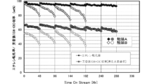
- FIG. 2 is a graph comparing reaction evaluation results of Example 1, Comparative Example 1, and Comparative Example 2.
- FIG. 3 is an X-ray diffraction spectrum showing a crystallization index measurement result of zeolite used in Example 2.
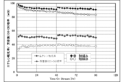
- FIG. 6 is a graph showing reaction / regeneration repeated deterioration behavior in Example 3 and Comparative Example 3.
- 6 is a graph showing reaction / regeneration repeated deterioration behavior in Example 4 and Comparative Example 4.
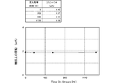
- 3 is an X-ray diffraction spectrum showing a crystallization index measurement result of zeolite used in Example 7. It is a graph which shows the change transition of the zinc content on a catalyst in the reference example 2. It is an apparatus figure of the fluid bed evaluation apparatus in Example 8.
- the present embodiment the embodiment of the present invention (hereinafter referred to as “the present embodiment”) will be described in detail.
- the present invention is not limited to this, and various modifications are possible without departing from the scope of the present invention. It is.
- the method for producing an aromatic hydrocarbon-containing compound comprises a reactor supply gas containing at least one selected from the group consisting of the following (1) to (4) as a raw material, MFI-type zeolite, and silica.
- a process for producing an aromatic hydrocarbon-containing compound by a fluidized bed reaction by contacting with a silica molded body catalyst containing the contained particles, wherein the silica molded body catalyst contains 0.1 to 1.0% by mass of phosphorus. And the ratio of the pore area in the particle cross section of the silica molded body catalyst is 30% or less with respect to the cross sectional area of the particles.
- an aromatic hydrocarbon-containing compound can be stably produced at high yield over a long period of time from ethane steam cracking gas (containing light hydrocarbons containing olefins), ethanol, methanol, dimethyl ether, and the like.
- the silica molded body catalyst in the present embodiment is a catalyst including particles containing MFI-type zeolite and silica.
- the catalyst contains 0.1 to 1.0% by mass of phosphorus and 0.1 to 5.0% by mass of zinc, and the ratio of the pore area in the particle cross section of the silica molded body catalyst is the cross sectional area of the particle. Is 30% or less.
- the silica molded body catalyst in the present embodiment preferably has a zeolite crystallization index determined from an X-ray diffraction spectrum of 3.3 or more.
- the average particle diameter of the silica molded body catalyst is preferably 20 to 300 ⁇ m, and the bulk density of the silica molded body catalyst is preferably 0.7 to 1.2 g / cm 3 . Furthermore, it is preferable that the corrosion index of the stainless steel obtained when the silica molded body catalyst is subjected to a predetermined test is 10,000 or less.
- the silica molded body catalyst in this embodiment has a structure in which the ratio of the pore area in the cross section of the particle is 30% or less with respect to the cross sectional area of the particle.
- the ratio of the pore area is preferably 20% or less, more preferably 15% or less, and further preferably 10% or less.
- the ratio of the pore area in the cross section of the particle here means a value measured as follows.
- the cross-sectional area of one particle observed at a magnification of 800 to 2000 times and the area of the void in the cross-section of the particle are measured by an image analyzer, and the area of the void relative to the cross-sectional area of the particle Calculate the percentage of.
- a series of operations are performed on 100 catalyst particles, and an arithmetic average (arithmetic average) is used as the ratio of the pore area in the cross section of the particles.
- the above-described “particle cross-sectional area” is a value including the area of the pores.
- both ends of the part of the circumference (opening) cut by “burst” are connected with a straight line so as to close the opening, and the straight line and the particle
- the area surrounded by the outer periphery is defined as the cross-sectional area of the particles.
- the ratio of the pore area is 30% or less, the mechanical strength of the particles tends to increase.
- hole area can be controlled to the said range, for example by preparing a catalyst according to [The manufacturing method of a silica molded body catalyst] mentioned later.
- the silica molded body catalyst in the present embodiment satisfies the above-mentioned ratio of the pore area, it has a dense structure with very few pores inside the particles, and as a result, the mechanical strength is extremely high, and the fluidized bed reaction.
- the catalyst When used in a vessel, the catalyst is less pulverized even when used for a long time, and a suitable fluid state can be stably maintained. Therefore, the catalyst is more suitable for an industrial process.
- the bulk density of the silica molded body catalyst in the present embodiment is preferably 0.7 to 1.2 g / cm 3 , more preferably 0.8 to 1.0 g / cm 3 .
- the bulk density of the silica molded body catalyst is measured by a conventional method using a Casa specific gravity measuring instrument (model “Z-2504” manufactured by Tsutsui Rika Kagaku Co., Ltd.). By setting the bulk density to 0.7 g / cm 3 to 1.2 g / cm 3 , it tends to be easier to maintain a stable fluid state when used in a fluidized bed reactor.
- the silica molded body catalyst in this embodiment contains a phosphorus element.
- the form of the phosphorus element is not particularly limited.
- a phosphorus polymer for example, polyphosphoric acid
- a phosphorus oxide for example, P 2 O 5
- a compound in which phosphorus is added to the aluminum of the zeolite, etc. Is mentioned. A plurality of them may be included.
- the phosphorus element has an effect of suppressing dealumination from the zeolite skeleton when the zeolite contains aluminum.
- the effect of preventing changes in the properties of the silica molded body catalyst due to dealumination becomes even more remarkable.
- the inclusion of a predetermined amount of phosphorus element provides an effect of improving the acidity of the catalyst surface, and as a result, an effect of suppressing deterioration due to coking.
- the aromatic hydrocarbon-containing compound unlike the production of propylene, etc., it is preferable to use a highly active catalyst because the yield can be increased as the conversion rate of the raw material is higher. The more active the catalyst, the more caulking degradation occurs.
- the conventional production method used a catalyst that has undergone pretreatment by steaming, etc., but according to the silica molded body catalyst in the present embodiment, both high catalytic activity and suppression of coking deterioration can be achieved. Therefore, the yield of the aromatic hydrocarbon-containing compound can be significantly increased without performing the pretreatment described above.
- pretreatment steaming for suppressing coking deterioration is unnecessary, and a high yield is stably maintained over a long period of time. it can.
- the content of phosphorus element in the silica molded body catalyst can be measured by a conventional method using a fluorescent X-ray analyzer (manufactured by Rigaku, trade name “RIX3000”). As measurement conditions at that time, a P-K ⁇ line can be used, and a tube voltage: 50 kV and a tube current: 50 mA can be employed.
- the content of the phosphorus element contained in the silica molded body catalyst in the present embodiment is 0.1 to 1.0% by mass with respect to the total mass of the silica molded body catalyst, preferably 0.00. It is 2 to 0.75% by mass, more preferably 0.25 to 0.65% by mass.
- the phosphorus element content is 0.1% by mass or more, the effect of suppressing coking deterioration in a high temperature region and the effect of suppressing dealumination of zeolite in a high temperature steam atmosphere are excellent. These effects largely depend on the P / Al ratio with the aluminum element contained in the zeolite framework existing in the silica molded body catalyst.
- the silica / alumina molar ratio in the present embodiment is in the range of 20 to 500, phosphorus If the element content is 0.1% by mass or more, the effect is great. If the content of the phosphorus element is 1.0% by mass or less, there is little corrosion of the stainless steel in a high-temperature steam atmosphere. In addition, content of the said phosphorus element can be controlled to the said range based on the carrying
- the silica molded body catalyst in this embodiment contains a zinc element.
- Zinc contained in the silica molded body catalyst in the present embodiment is metal zinc, zinc oxide, or zinc existing as an ion at the zeolite cation site.
- the content of the zinc element in the silica molded body catalyst can be measured by a conventional method using a fluorescent X-ray analyzer (manufactured by Rigaku, trade name “RIX3000”). As measurement conditions at that time, a P-K ⁇ line can be used, and a tube voltage: 50 kV and a tube current: 50 mA can be employed.
- the content of the zinc element contained in the silica molded body catalyst in the present embodiment is 0.1 to 5.0% by mass, preferably 0.5 to 3.5% by mass with respect to the total mass of the silica molded body catalyst. % By mass, more preferably 1.5 to 2.5% by mass.
- content of zinc element is 0.1% by mass or more, the yield of the aromatic hydrocarbon-containing compound tends to increase.
- content of zinc element is less than 0.1% by mass, the yield of the aromatic hydrocarbon-containing compound is not sufficient, and even if it exceeds 5.0% by mass, there is no yield improvement effect.
- content of the said zinc element can be controlled to the said range based on the loading method of the zinc mentioned later.
- the silica molded body catalyst in the present embodiment is a catalyst having a strength required as a fluidized bed catalyst while adopting an inert silica binder that is advantageous for coking deterioration.
- the wear loss which is an index of the mechanical strength of the silica molded body catalyst particles, is evaluated in two stages, short-term and long-term, and can be measured by the following method.
- a powder ascending part having an inner diameter of 35 mm and a length of 700 mm, and a powder separating part having an inner diameter of 110 mm and a length of 600 mm, each having an orifice having three 0.4 mm holes at the gas inlet.
- a thing provided with a fine-powder collection part is prepared. After 52.5 g of silica compact catalyst particles containing 2.5 g of water at room temperature are put into a jet flow device, air containing water corresponding to the vapor pressure is circulated from the gas inlet at 5.8 NL / min.
- Wear loss is determined according to the following equation.
- Short-term wear loss (mass%) A / (BC) x 100
- A represents the mass (g) of the silica compact catalyst fine powder recovered 5 to 20 hours after the start of measurement
- C represents the silica compact catalyst fine powder recovered 0 to 5 hours after the start of measurement.
- the mass (g) is indicated
- B indicates the total mass (g) of the silica molded body catalyst subjected to the test.
- Long-term wear loss (mass%) (A + D) / (BC) ⁇ 100
- D indicates the mass (g) of the silica compact catalyst fine powder recovered 20 to 70 hours after the start of measurement.
- the short-term wear loss of the silica molded body catalyst in the present embodiment is preferably 2% by mass or less, more preferably 1% by mass or less, and further preferably 0.5% by mass or less.
- the long-term wear loss is preferably 3% by mass or less, more preferably 2% by mass or less, and further preferably 1% by mass or less. Since the wear loss is small, the outflow of the catalyst can be suppressed in the use of the fluidized bed catalyst in the present embodiment, and the aromatic hydrocarbon-containing compound can be produced stably for a long period of time.
- the silica molded body catalyst in this embodiment contains phosphorus as described above, when a specific catalyst containing a certain amount or more of phosphorus element is used, in an atmosphere in which high-temperature steam is present, it is used as a material for industrial equipment. There is concern over the occurrence of significant corrosion in commonly used stainless steel. As corrosion of stainless steel progresses, in the worst case, serious problems may occur in plant operation, such as perforations in the reactor. In the method for producing an aromatic hydrocarbon-containing compound of this embodiment, since the catalyst tends to be exposed to high-temperature steam in both the reactor and the regenerator, it is particularly preferable to suppress corrosion of stainless steel.
- the silica molded body catalyst in the present embodiment has a corrosion index of preferably 10,000 or less, more preferably 8000 or less, and even more preferably 5000 or less from the viewpoint of preserving stainless steel in the case of use accommodated in a reaction vessel made of stainless steel.
- the corrosion index representing the corrosivity of stainless steel is a value measured by the following method. The corrosion index can be controlled within the above preferred range by preparing a catalyst according to the phosphorus loading method described below.
- the silica molded body catalyst is pressed and compacted by a compression molding machine and then crushed to particles of 6 to 16 mesh.
- a quartz reaction tube is filled with 12 g of the particles together with a test piece (20 mm ⁇ 10 mm, thickness 1 mm) of stainless steel (SUS304).
- the quartz reaction tube is maintained at 550 ° C. for 7 days while flowing a gas composed of 80 vol% of water vapor and 20 vol% of nitrogen.
- the test piece after the test is observed with a microscope, and the corrosion index is measured according to the following formula.
- Corrosion index number of corrosion holes (pieces / cm 2 ) ⁇ average corrosion pore diameter ( ⁇ m) ⁇ average corrosion depth ( ⁇ m)
- corrosion pitting number is obtained by measuring the number of holes generated by corrosion of the test piece 1 cm 2 per after the test.
- the average corrosive pore diameter is obtained as an arithmetic average value obtained by measuring the hole diameter of holes generated by corrosion.
- the average corrosion depth is obtained as an arithmetic average value obtained by cutting the test piece after the test and measuring the depth of the hole caused by the corrosion from the obtained cross section.
- corrosion refers to a phenomenon in which a metal is altered and destroyed by a chemical reaction or an electrical reaction.
- the zeolite contained in the silica molded body catalyst in this embodiment is MFI type zeolite. That is, the zeolite is classified into the MFI structure by the skeletal structure type according to the IUPAC recommendation, and specifically, the zeolite is ZSM-5 type.
- the zeolite contained in the silica molded body catalyst is an MFI type zeolite, it exhibits high activity and selectivity and high resistance to coking deterioration in the catalytic conversion reaction of olefin and alcohol.
- the MFI type zeolite is a medium pore size zeolite.
- the crystallization index determined from the X-ray diffraction spectrum of the MFI type zeolite in the present embodiment is preferably 3.3 or more.
- the crystallization index is preferably 3.5 or more, more preferably 4.0 or more.
- means for efficiently obtaining MFI-type zeolite by hydrothermal synthesis is not limited to the following.
- ammonium salts ammonium salts
- urea compounds amines
- hydrothermal synthesis using alcohols and the like
- inorganic cations and anions are known to be involved in the structure, and zeolite synthesis depends on the combined action of each component.
- a method of synthesizing using a seed slurry described in JP-A-10-52646, or a silicate ester described in WO02 / 064560 examples include a method of synthesizing in the presence of alcohol and tetrapropylammonium salt as a source (an aluminum source needs to be added as appropriate so as to obtain a desired silica-alumina molar ratio of zeolite used in the present embodiment).
- a commercially available zeolite can also be used, and such a commercially available product is not limited to the following, for example, MFI manufactured by Sud Chemie AG. -27 and Zolist International's ZD03030 (MFI-42).
- the silica alumina (SiO 2 / Al 2 O 3 ) molar ratio of the MFI type zeolite is preferably 20 to 500, more preferably 25 to 300.
- a more preferable silica-alumina molar ratio is appropriately selected depending on the raw material used. For example, when a light hydrocarbon containing olefin or ethanol is used as a raw material, 25 to 100 is preferable, and when methanol or dimethyl ether is used as a raw material, 150 to 300 is preferable.
- the silica-alumina molar ratio can be measured by the method described in the examples described later. By appropriately selecting the SDA used, the silica / alumina molar ratio charged during zeolite synthesis, temperature, time, etc. It can be controlled within a preferable range defined in the form.
- the average particle diameter of the silica molded body catalyst is preferably 20 to 300 ⁇ m.
- the average particle diameter can be measured by the method described in the examples described later, and is controlled within the preferable range by spray-drying the raw slurry by the method described in the catalyst preparation step (ii): drying step described later. can do.
- the method for producing a silica molded body catalyst in the present embodiment is a catalyst including particles containing MFI-type zeolite and silica, and includes 0.1 to 1.0% by mass of phosphorus and 0.1 to 5.0% by mass.
- the method is not particularly limited as long as it is a method for obtaining a silica molded body catalyst containing a zinc and having a pore area ratio of 30% or less with respect to the cross-sectional area of the particles.
- various conditions as described in detail below may be adjusted.
- the method for producing a silica molded body catalyst in the present embodiment includes (i): a step of preparing a raw material mixture containing zeolite and silica [raw material mixture preparing step], and (ii): spray drying the raw material mixture.
- a step of firing at a lower temperature than the main firing step [pre-firing step] may be included before the [main firing step].
- Raw material mixture preparation process is preferably a raw material mixture comprising zeolite, silica, and at least one water-soluble compound selected from the group consisting of nitrate, acetate, carbonate, sulfate and chloride. (Hereinafter, also referred to as “raw material slurry”).
- the raw material zeolite is preferably in a state where the primary particles of the zeolite are dispersed.
- the zeolite has a primary aggregation of about 0.05 to 10 ⁇ m in which primary particles are partially bonded to each other to form secondary aggregation.
- zeolite with secondary agglomeration is formed together with a binder such as silica, the surface of the formed particles becomes rough, and pores are easily formed inside the particles, and the mechanical strength tends to be weakened.
- subsequent aggregation it is preferably used after being mechanically pulverized using a jet mill or the like.
- a ball mill or a jet mill that performs pulverization processing by converting high-pressure air into an ultra-high speed jet can be used, and the average particle diameter of the zeolite is in the range of 0.05 to 5 ⁇ m. Is preferably deagglomerated.
- the agglomeration form of zeolite can be observed with an electron microscope.
- the average particle diameter of zeolite can be measured with a laser diffraction / scattering particle size analyzer (for example, trade name “BlueRaytrac” manufactured by Microtrack Bell).
- the silica molded body catalyst in this embodiment uses silica as a binder.
- an alumina binder has been preferably used in this field for easily obtaining mechanical strength and stabilizing zinc that imparts dehydrogenating ability.
- alumina has an active site, in this embodiment using olefin, alcohol, or the like as a raw material, coking deterioration of the catalyst is promoted.
- the silica binder is inactive to this reaction and is extremely advantageous for coking deterioration. Suppression of coking deterioration eventually leads to a decrease in regeneration frequency, and is effective in suppressing permanent deterioration of the catalyst.
- silica can be employed as the binder.
- silica molded body catalyst that can sufficiently withstand industrial use in a fluidized bed reaction even though silica is used as a binder.
- Silica used for the catalyst raw material can include colloidal silica and water glass.
- the colloidal silica is preferably prepared by an ion exchange method.
- water glass sodium silicate
- water glass is often used as a raw material for producing a fluidized bed catalyst.
- sodium silicate sodium silicate
- it is inferior compared with the case where water glass is not used, in terms of the shape of the catalyst particle surface and catalyst performance. It has been found. That is, when sodium silicate is used as the raw material for the binder silica, sodium that is a catalyst poison for the solid acid catalyst tends to be contained in a large amount in the catalyst.
- the silica raw material contains water glass
- ion exchange is performed after the firing step, sodium contained in the fired body tends to be difficult to remove.
- the ion exchange treatment is not particularly limited. For example, at 10 to 95 ° C., 0.1 to 48 hours, 0.1 to 3 molar aqueous solutions of mineral acids such as nitric acid, sulfuric acid and hydrochloric acid, and / or ammonium nitrate aqueous solutions are used. It is performed by bringing a (metal) cation-containing aqueous solution into contact with a dry powder. Thereafter, it is washed with water, dried, and subjected to the firing step of step (iii).
- each support of phosphorus and zinc takes into account the ion exchange treatment. It is preferable to carry out. For example, it is preferable to carry each of phosphorus and zinc after the ion exchange treatment.
- the surface of the catalyst particles tends to be smooth.
- the surface of (particles) is smooth means that the surface of the particles does not appear uneven when observed with a 150 ⁇ magnification micrograph.
- colloidal silica is the main component, the sodium content in the raw material is small, so that sodium can be adjusted to a preferred amount by a simpler operation without performing the above ion exchange step.
- colloidal silica is simply used instead of water glass in the prior art, the catalyst formed by spray drying tends to form a large cavity in the center, and the strength of the catalyst particles tends to decrease. .
- the strength and shape of the catalyst are important for maintaining a stable yield over a long period of time, and the catalyst performance can be improved without deteriorating the shape of the catalyst particle surface.
- Ratio of silica obtained from colloidal silica relative to the total amount of silica (excluding silica constituting zeolite) contained in the silica molded body catalyst (hereinafter simply referred to as “colloidal silica contained in raw material mixture”).
- the ratio is also preferably as high as possible. Specifically, it is preferably 50% by mass or more, more preferably 60% by mass or more, still more preferably 70% by mass or more, and still more preferably. It is 80 mass% or more, Most preferably, it is 90 mass% or more.
- the ratio of colloidal silica to the total amount of silica (excluding silica constituting zeolite) contained in the raw material mixture is preferably 50% by mass or more, more preferably 60% by mass or more, More preferably, it is 70 mass% or more, More preferably, it is 80 mass% or more, Most preferably, it is 90 mass% or more.
- the ratio of the colloidal silica to the total amount of silica contained in the raw material mixture is, for example, when the silica source contained in the raw material mixture is water glass and colloidal silica (silica contained in the colloidal silica) ⁇ 100 / (Silica contained in colloidal silica + silica contained in water glass) [%] Means.
- the surface of the resulting catalyst tends to be smoother.
- protrusions and depressions are observed on the surface even when observed at 1600 times or more. Fewer particles (40% or less). “Protrusions and depressions” indicate a state in which local irregularities are generated on the surface, and are different from a state in which a linear “crack” is formed on the surface.
- colloidal silica prepared by the ion exchange method for example, a commercially available product can be used. Colloidal silica stabilized with ammonia or amine is particularly preferred because of its low alkali metal content.
- the content (mass basis) of the alkali metal in the colloidal silica is preferably as small as possible, more preferably 1000 ppm or less as an alkali metal, and still more preferably 250 ppm or less.
- the alkali metal content is preferably 5000 ppm or less, more preferably 3000 ppm or less, still more preferably 1000 ppm or less, still more preferably 300 ppm or less, particularly preferably based on the total mass of the silica molded body catalyst. 100 ppm or less.
- the alkali metal content is 5000 ppm or less, sufficient catalytic activity tends to be ensured.
- the catalyst was dissolved in aqua regia at 210 ° C. using a microwave (Milestone Co., Ltd., model: ETOS PLUS). The residue is filtered. Thereafter, the amount of alkali metal in the filtrate is measured by an ordinary method using ICP emission spectrometry.
- the content of alkali metal in the silica molded body catalyst can be derived from the amount of alkali metal contained in the filtrate.
- the measurement conditions for ICP emission analysis can be set to high frequency power: 1 kW, plasma gas: 13 L / min, sheath gas: 0.15 L / min, nebulizer gas: 0.25 L / min.
- the average particle size of silica contained in the colloidal silica is preferably 3 to 50 nm, more preferably 4 to 25 nm. There exists a tendency for the mechanical strength of a shaping
- the average particle size of silica can be measured with a dynamic light scattering (DLS) particle size distribution measuring device (for example, trade name “Nanotrac Wave-EX150” manufactured by Microtrack Bell).
- DLS dynamic light scattering
- At least one water-soluble compound selected from the group consisting of nitrate, acetate, carbonate, sulfate and chloride is added to the raw slurry.
- salt refers to a compound produced by a neutralization reaction between an acid and a base, as described on page 1014 of the Encyclopedia of Chemistry, Vol. 1, 39th edition (Kyoritsu Publishing Co., Ltd., June 15, 2006) And consisting of an acid negative component and a base positive component.
- the “water-soluble compound” means a compound having a solubility of 1 g or more in 100 g of water at 25 ° C.
- the water-soluble compound is preferably a compound having a solubility of 10 g or more with respect to 100 g of water at 25 ° C., and is not particularly limited, but generally includes an ammonium salt, an aluminum salt, and a sodium salt.
- a more preferable water-soluble compound from the viewpoint of the constituent requirements of the present embodiment is an ammonium salt that is highly water-soluble and can be decomposed and removed from the catalyst in the firing step described below. More specifically, the water-soluble compound is more preferably one or more ammonium salts selected from the group consisting of ammonium nitrate, ammonium acetate, ammonium carbonate, ammonium sulfate and ammonium chloride, and particularly preferably ammonium nitrate.
- the amount of the water-soluble compound added to the raw slurry is in the range of 0.01 to 5.0 in terms of mass ratio to the silica contained in the colloidal silica (hereinafter referred to as “water-soluble compound / colloidal silica ratio”). preferable.
- the amount of the water-soluble compound added is more preferably in the range of 0.03 to 3.0, still more preferably in the range of 0.05 to 2.0, still more preferably 0.1 to 1.0. And particularly preferably in the range of 0.25 to 0.5.
- the raw material slurry is preferably acidic.
- the pH of the raw material slurry is preferably 0.01 to 3.0, more preferably 0.1 to 2.0, and further preferably 0.5 to 1.5.
- the colloidal silica tends to be destabilized and gelled. Particles with higher mechanical strength can be obtained by preventing gelation of colloidal silica and spray drying while keeping the sol form.
- a) and b) To the slurry obtained by adding zeolite to colloidal silica, an acid such as nitric acid, sulfuric acid, hydrochloric acid, etc. is added to adjust the pH in advance, and then a water-soluble compound is added thereto to add an acidic raw material slurry. How to prepare.
- an acid such as nitric acid, sulfuric acid, hydrochloric acid, etc. is added to adjust the pH in advance, and then a water-soluble compound is added thereto to add an acidic raw material slurry. How to prepare.
- Acids such as nitric acid, sulfuric acid, and hydrochloric acid are added to colloidal silica to adjust pH in advance, then a water-soluble compound is added thereto, and then zeolite is added to prepare an acidic raw material slurry. Method.
- the solid content concentration of the raw material slurry after addition of zeolite, colloidal silica, water-soluble compound, etc. is preferably 5 to 60% by mass, more preferably 15 to 40% by mass.
- water may be appropriately added to the raw slurry.
- the solid content concentration of the raw material slurry is the ratio of the mass of the residue obtained by drying the raw material slurry at 100 ° C. with respect to the total mass of the raw material slurry.
- the temperature at which the raw slurry is prepared is preferably 5 to 95 ° C, more preferably 10 to 70 ° C, and still more preferably 10 to 40 ° C.
- the stirring power and stirring time at which the raw material components are sufficiently mixed with each other are selected.
- the stirring time is preferably 0.5 to 48 hours, more preferably 1 to 5 hours.
- Step (ii) is a step of obtaining a dry powder by spray drying the raw slurry obtained in the step (i).
- the spray drying is preferably performed using an industrially used spray dryer (spray dryer).
- the method of spraying the raw material slurry is not particularly limited, and can be performed by, for example, a rotating disk method, a two-fluid nozzle method, a high pressure nozzle method, or the like.
- a particularly preferable spraying method is a rotating disk method.
- the spray drying can be performed by spraying the raw slurry together with a fluid such as air heated by steam, an electric heater or the like, or an inert gas such as nitrogen or helium.
- the fluid temperature at the inlet of the spray dryer is preferably 100 to 300 ° C, more preferably 150 to 270 ° C.
- the fluid temperature at the outlet of the spray dryer is preferably 80 to 200 ° C, more preferably 90 to 150 ° C.
- the average particle size of the silica molded body catalyst particles in the form after firing is small, and can be suitably adjusted so that the average particle size is preferably in the range of 20 to 300 ⁇ m.
- Step (iii) is a step of firing the dry powder obtained in the above step (ii) to obtain a fired powder.
- the drying of the dry powder is not particularly limited, and can be performed using, for example, a muffle furnace, a rotary furnace, a tunnel furnace, a tubular furnace, a fluidized firing furnace, a kiln furnace, or the like.
- An industrially preferred method is a method of firing using a continuous feed rotary kiln furnace.
- the firing temperature is preferably 400 to 1000 ° C., more preferably 500 to 800 ° C., from the viewpoint of improving the strength of the catalyst particles.
- the calcination time is preferably 0.1 to 48 hours, more preferably 0.5 to 24 hours, and further preferably 1 to 10 hours from the viewpoint of the strength of the catalyst particles. Firing of the dry powder is preferably performed in an atmosphere of an inert gas such as air, water vapor, nitrogen, helium, or the like. Moreover, you may carry out under pressure and pressure reduction. The firing may be performed repeatedly and repeatedly.
- an inert gas such as air, water vapor, nitrogen, helium, or the like.
- Step (v): Pre-baking step In step (v), a part or all of nitrate, acetate, carbonate, sulfate, and chloride added as a water-soluble compound is removed from the dry powder obtained in step (ii). It is a process.
- the pre-baking step can be performed with the same apparatus and conditions as in the above (iii) main baking step, except that the baking temperature is preferably 300 to 400 ° C., more preferably 330 ° C. to 380 ° C.
- the removal amount of the salt component can be calculated from the change in weight before and after firing.
- the added water-soluble compound forms a state of being adsorbed on the surface of the colloidal silica silica particles,
- the silica particles are not closely bonded to each other.
- the vapor inside the particles obtained from the droplets can be quickly moved from between the silica particles to the outside without being confined, and the pressure inside the particles does not increase or negative pressure does not occur.
- a structure in which zeolite and silica are densely and uniformly filled with very few pores on the particle surface and pores inside the particle is formed.
- A) Raw material solution The metal supporting step in this embodiment is performed using a solution containing metal raw materials (phosphorus and zinc) to be supported (hereinafter also referred to as “metal raw material solution”).
- the metal raw material solution is preferably an aqueous solution.
- a zinc component is zinc and zinc oxide, zinc hydroxide, zinc nitrate, zinc carbonate, zinc sulfate, zinc chloride, zinc acetate and Examples include salts such as zinc oxalate.
- the form of the phosphorus element used in the metal raw material solution is not particularly limited, and examples thereof include phosphoric acid and / or a phosphate solution. Among these, the use of the phosphate solution lowers the corrosion index. This is preferable because it tends to be possible.
- Specific examples of phosphoric acid include phosphoric acid and pyrophosphoric acid
- specific examples of phosphate include ammonium phosphate, diammonium monohydrogen phosphate, monoammonium dihydrogen phosphate, and sodium ammonium hydrogen phosphate.
- ammonium phosphate potassium hydrogen phosphate, aluminum hydrogen phosphate, sodium phosphate, potassium phosphate and the like.
- an ammonium phosphate salt having a relatively high solubility in water is preferable, and more preferably at least one selected from the group consisting of ammonium phosphate, ammonium monohydrogen phosphate, and ammonium dihydrogen phosphate. These may be used alone or in combination of two or more.
- the supporting method of the metal supporting step in this embodiment is performed by a known method, that is, generally, an adsorption method, an equilibrium adsorption method, a pore filling method, an evaporation to dryness method, a spraying method, and the like. .
- a known method that is, generally, an adsorption method, an equilibrium adsorption method, a pore filling method, an evaporation to dryness method, a spraying method, and the like.
- a known method that is, generally, an adsorption method, an equilibrium adsorption method, a pore filling method, an evaporation to dryness method, a spraying method, and the like.
- a phosphate solution is prepared by using a mixer, a blender, a kneader or the like to make the dried body flow.
- the dry body is brought into contact with the solution containing the phosphorus raw material while adjusting the amount of the solution containing the supported phosphorus raw material so that the dry body maintains the powder state.
- the amount of the solution so as to maintain the powder state that is, the zeolite and the silica compact do not form a slurry state, it is not necessary to evaporate the solvent, and there is no adhesion of the powder to the apparatus. Industrial continuous production becomes extremely easy, and the corrosion index tends to be smaller than when a slurry state is formed.
- a phosphorus raw material solution in the range of 0.2 to 0.5 (mass ratio) with respect to the dried product, and more preferably 0.2 to 0.4 (mass ratio).
- the temperature at that time is preferably 10 to 95 ° C. It is preferable that the solution is further mixed with a stirring strength with a time that the solution has a sufficient affinity with the dried product, and usually 0.5 to 48 hours.
- the loading of zinc and phosphorus on the silica molded body catalyst in the present embodiment may be performed simultaneously, and the order of loading is not limited.
- zinc phosphate salt is generated when the metal raw material solution is mixed, and control of the amount of metal supported and uniformity may be inferior.
- Step (C-2) It is supported on the dried product obtained in step (ii).
- (C-3) Supporting the pre-fired powder obtained in step (v).
- (C-4) Step (iii) It is supported on the silica molded body catalyst after completion of the calcination.
- it when carrying
- a more preferable metal loading prescription is a prescription for carrying the pre-fired powder obtained in (C-3) step (v).
- a preferable method for producing a silica molded body catalyst in the present embodiment 1) various catalyst raw materials (zeolite, colloidal silica, nitric acid, ammonium nitrate) are prepared to prepare a raw slurry, and 2) The raw material slurry is spray-dried to obtain a dried product, 3) the obtained dried product is pre-fired, 4) phosphorus is supported, 5) this is fired, and 6) zinc is added to the resulting phosphorus-supported molded catalyst. And 7) a method of refiring.
- various catalyst raw materials zeolite, colloidal silica, nitric acid, ammonium nitrate
- a reactor supply gas containing at least one selected from the group consisting of the following (1) to (4) as a raw material is used.
- the light hydrocarbon refers to paraffins and olefins having 1 to 5 carbon atoms
- the “olefin” referred to in this embodiment includes cycloparaffins in addition to linear and branched olefins having 2 to 5 carbon atoms. .
- water is present in the reaction raw material or in the mixed system of the reaction raw material and the silica molded body catalyst, that is, water is present in the reaction system in which the catalytic conversion reaction occurs.
- (2) ethanol and (3) methanol are used alone or in combination, a dehydration reaction occurs due to contact between the raw material and the zeolite catalyst. It is not necessary to positively add water. Since the dehydration reaction takes place prior to the catalytic conversion reaction that produces an aromatic hydrocarbon-containing compound by contact with the zeolite catalyst, when selecting the above raw material group, the reaction system in which the catalytic conversion reaction occurs is any case. Coexist with water.
- the “reactor supply gas” refers to the entire gas introduced into the reaction system, and therefore includes a gas such as nitrogen that is inert to the catalytic conversion reaction. As described above, in the present embodiment, it can be directly subjected to the fluidized bed reaction without passing through the step of removing moisture in the reaction raw material, which is advantageous from the viewpoint of reducing the number of steps.
- the catalytic conversion is a catalytic reaction that proceeds at the interface of a heterogeneous phase, that is, a reaction in which a reaction material in a gas phase and / or a liquid phase is brought into contact with a solid catalyst.
- a heterogeneous phase that is, a reaction in which a reaction material in a gas phase and / or a liquid phase is brought into contact with a solid catalyst.
- catalytic conversion of ethylene when a raw material containing ethylene is supplied to a reactor filled with a silica molded body catalyst, the raw material comes into contact with the catalyst, and at least a part of ethylene contained in the raw material undergoes a conversion reaction to produce an aromatic hydrocarbon. A containing compound is produced.
- the amount of water supply is 10 mol% or more of the reactor supply gas, preferably 15 mol% or more, More preferably, it is 20 to 50 mol%.
- the presence of water was thought to have a great influence on the aging of the catalyst.
- the aromatic hydrocarbon-containing compound can be stably produced in a high yield over a long period of time.
- reaction conditions of this embodiment In this embodiment, the reaction is by a fluidized bed process.
- the reaction temperature is preferably 400 to 600 ° C, more preferably 450 to 550 ° C.
- the partial pressure of the hydrocarbon raw material is usually 0.01 to 1 MPa, preferably 0.05 to 0.3 MPa.
- the LV (gas linear velocity) due to the reaction substrate is in the range of 15 to 120 cm / sec, preferably 25 to 100 cm / sec, more preferably 35 to 90 cm / sec in normal operation results.
- the conversion rate of olefins is higher among the raw material components. Accordingly, the concentration of olefins having 2 to 5 carbon atoms (excluding coexisting water) in the reactor outlet gas is 25% by mass or less, preferably 20% by mass or less, and more preferably 15% by mass or less.
- the olefins in this embodiment include dienes, acetylenes, and cycloparaffins.
- the yield of the aromatic hydrocarbon-containing compound can be increased by increasing the olefin conversion rate.
- the activity for example, simply reducing the silica-alumina ratio of the zeolite contained, there is a problem that the activity deterioration due to the increase in the amount of coke and the activity deterioration accompanying the desorption of aluminum in the zeolite lattice are promoted. Arise.
- the aromatic hydrocarbon-containing compound since the deterioration of the activity of the catalyst and the reduction of the scattering of zinc on the catalyst can be suppressed, the aromatic hydrocarbon-containing compound can be stably produced over a long period of time with a high yield. it can.
- the silica molded body catalyst in the present embodiment has high resistance to coking deterioration, but as the reaction process in the present embodiment becomes longer, coke deposition on the catalyst increases and the catalytic activity tends to decrease. It is in. In that case, a part of the silica molded body catalyst may be continuously or intermittently extracted from the fluidized bed reactor, and coke adhered to the catalyst may be burned and removed in the regenerator using a gas containing oxygen. As a result, the silica molded body catalyst is regenerated, and by returning the regenerated silica molded body catalyst to the fluidized bed reactor, the reaction can be continued for a long time while maintaining high catalytic activity.
- the silica molded body catalyst subjected to the conversion reaction in the reactor is supplied to the regenerator.
- the coke amount of the silica molded body catalyst in the reactor can be kept constant.
- the catalyst in the reactor can always be maintained at a constant activity, and the production amount of the aromatic hydrocarbon-containing compound can be made constant as compared with intermittent regeneration. preferable.
- the method for producing an aromatic hydrocarbon-containing compound according to the present embodiment includes a first derivation step for deriving a coke adhesion catalyst containing a silica molded body catalyst and coke from a reactor to a fluidized bed regenerator, and a fluidized bed regenerator.
- a second deriving step of deriving the regenerated silica molded body catalyst from the fluidized bed regenerator to the reactor from the fluidized bed regenerator is preferred. Although these steps may be performed intermittently, it is more preferable to perform them continuously.
- the silica molded body catalyst introduced into the fluidized bed reactor partially includes a silica molded body catalyst with a small amount of coke attached thereto.
- the adhering coke is not removed completely at the time of regeneration, but remains as much as the pre-coke.
- the present embodiment will be described more specifically by way of examples.
- the present embodiment is not limited only to these examples.
- the measuring method performed in the Example and the comparative example is as follows.
- the measuring method of various physical properties is as follows. (1) Zeolite structure type X-ray diffraction pattern of zeolite is measured using a powder diffraction X-ray apparatus (trade name “RINT”, manufactured by Rigaku), and the structure type is determined by referring to the known diffraction pattern of zeolite. Identified. The measurement conditions were set to Cu cathode, tube voltage: 40 kV, tube current: 30 mA, scan speed: 1 deg / min.
- Measurement conditions are set to high frequency power: 1 kW, plasma gas: 13 L / min, sheath gas: 0.15 L / min, nebulizer gas: 0.25 L / min, Si measurement wavelength: 251.60 nm, Al measurement wavelength: 396.152 nm did.
- Average particle diameter of the silica molded body catalyst was measured using a laser diffraction / scattering particle size distribution meter (trade name “MT3000” manufactured by Microtrack Bell Co., Ltd.) according to the attached manual. The average particle size was measured.
- particles having a diameter within a range of ⁇ 10% with respect to the average particle diameter of the catalyst particles were selected, and the cross section close to the center was observed instead of the surface portion of the spherical particles.
- the cross-sectional area of one particle observed at a magnification of 800 to 2000 times and the area of the void in the cross-section of the particle are measured by an image analyzer, and the area of the void relative to the cross-sectional area of the particle The percentage of was calculated.
- the series of operations was performed on 100 catalyst particles, and the arithmetic average (arithmetic average) was taken as the ratio of the pore area in the cross section of the particles.
- the above-mentioned “cross-sectional area of the particles” is a value including the area of the pores.
- both ends of the part of the circumference (opening) cut by “burst” are connected with a straight line so as to close the opening, and the straight line and the particle
- the area surrounded by the outer periphery was defined as the cross-sectional area of the particles.
- Corrosion index number of corrosion holes (pieces / cm 2 ) ⁇ average corrosion pore diameter ( ⁇ m) ⁇ average corrosion depth ( ⁇ m) (The number of corroded holes was the number of holes generated by corrosion per 1 cm 2 of the test piece after the test.
- the average corrosive hole diameter was obtained by measuring the hole diameter of holes generated by corrosion and calculating the arithmetic average value thereof.
- the average corrosion depth was obtained as an arithmetic average value obtained by cutting the test piece after the test and measuring the depth of the hole caused by the corrosion from the obtained cross section.
- Example 1 Preparation of fluidized bed catalyst [hydrothermal synthesis of raw zeolite]
- Special No. 3 sodium silicate (Fuji Chemical Co., Ltd., SiO 2 25 mass%, Na 2 O 8 mass%) 92 kg, water 95 kg, aluminum sulfate 16-hydrate 7.3 kg, and sulfuric acid (purity 97%) 3.0 kg
- a solution prepared by dissolving 1.15 kg of 1,3-dimethylurea in 150 kg of water was added with stirring to obtain a homogeneous gel.
- This gel was charged into a 600 liter autoclave and hydrothermally synthesized at 160 ° C. for 30 hours with stirring to obtain a Na-type ZSM-5 zeolite slurry.
- FIG. 1 shows an X-ray diffraction spectrum of a sample obtained by adding 1 g of rutile type titania to 5 g of the obtained H-type ZSM-5 zeolite and collecting it with an electric mortar for 30 minutes. From the measurement result of X-ray diffraction, the crystallization index of H-type ZSM-5 zeolite was determined to be 3.73. The silica / alumina molar ratio (SAR) was 40.
- Step 1 Preparation of raw material mixture slurry
- Step 2 Preparation of raw material mixture slurry
- 882 g of 34 mass% colloidal silica manufactured by Nalco
- 18 g of 61 mass% nitric acid aqueous solution manufactured by Wako Pure Chemicals, special grade reagent
- pH 1, and ammonium nitrate
- 100 g of a drug was added.
- stirring this silica solution 300 g of the zeolite obtained above was added, and finally 1034 g of water was added to prepare a 30% by mass raw material mixture, and this raw material mixture was further stirred at 25 ° C. for 1 hour.
- Step 3 Pre-baking process
- the spray-dried product obtained in step 2 was calcined in a muffle furnace at 350 ° C. for 1 hour in an air atmosphere to remove the ammonium nitrate added in step 1, and a denitration product composed only of zeolite and silica was prepared.
- Phosphate was supported on the obtained denitration product as follows. 9.8 g of diammonium hydrogen phosphate (manufactured by Wako Pure Chemicals, special grade reagent, solubility in 100 g of water: 131 g (15 ° C.)) was dissolved in ion-exchanged water to prepare 188 g of an aqueous phosphate solution. Phosphate aqueous solution was sprayed evenly at 25 ° C. while 510 g of the denitrated product was filled in a powder stirrer (manufactured by Aichi Electric Co., Ltd., rocking mixer) and the powder was flowing. The dried body did not become a slurry and maintained a powder state.
- Step 6 Zinc loading treatment step 46.4 g of zinc nitrate hexahydrate (manufactured by Wako Pure Chemicals, special grade reagent) was added to a 2 L eggplant flask and dissolved in 500 g of ion-exchanged water. Subsequently, 500 g of the phosphor-supported calcined silica molded body catalyst obtained in Step 5 was added to the eggplant flask and dried under reduced pressure at 80 ° C. under a pressure of 250 mmHg to obtain a zinc-supported dry body.
- Step 7 Re-baking step
- the obtained zinc-supported dry body was calcined in a muffle furnace at 600 ° C. for 1 hour in an air atmosphere to obtain a zinc / phosphorus-supported silica molded body catalyst A.
- the crystallization index of the zeolite contained in the catalyst A is based on the zeolite content estimated from the contents of silica, phosphorus and zinc, or the Al amount measured by completely dissolving the molded body and the silica alumina ratio of the zeolite.
- the amount of titania added to the molded body catalyst was calculated and measured.
- the crystallization index determined by the former measurement method was defined as crystallization index (1), and the crystallization index determined by the latter measurement method was defined as crystallization index (2).
- the average particle diameter of the silica molded body catalyst was 51 ⁇ m.
- the bulk density of the silica molded body catalyst was 0.93 g / cm 3 .
- 4-1) The short-term wear loss of the silica molded body catalyst particles was 0.2% by mass.
- 4-2) Long-term wear loss of the silica molded body catalyst particles was 0.65% by mass.
- the void area ratio of the silica molded body catalyst particles was 5%.
- the corrosion index of stainless steel in a high-temperature steam atmosphere was 3000.
- the crystallization index (1) of zeolite in the silica molded body catalyst was 3.70, and the crystallization index (2) was 3.75.
- the silica molded body catalyst A has a shape and strength suitable for a fluidized bed catalyst, is particularly excellent in wear resistance over a long period of time, and is stainless steel even when operated for a long time in a high-temperature steam atmosphere. Material corrosion is unlikely to occur.
- Example 1 Example 1 except that the catalyst (silica molded body catalyst B) which does not carry out steps 3 and 4 (not containing P) among the preparation procedures of the silica molded body catalyst described in Example 1 was used as the catalyst. In the same manner as above, a fluid bed type ethanol conversion reaction was carried out. The results are shown in Table 1.
- Example 2 A fluidized bed type ethanol was prepared in the same manner as in Example 1 except that a catalyst was prepared in the same manner as in Example 1 and a catalyst (silica molded body catalyst C) that did not perform steps 6 and 7 (not containing Zn) was used. A conversion reaction was carried out. The results are shown in Table 1.
- the silica molded body catalyst of this embodiment has high aromatic hydrocarbon-containing compound yield and exhibits extremely high resistance to coking deterioration by containing phosphorus. I understand that. Furthermore, it can be seen from Example 1 and Comparative Example 2 that the silica molded body catalyst of the present embodiment has a high aromatic hydrocarbon-containing compound yield by containing zinc.
- Example 2 [Hydrothermal synthesis of raw material zeolite] To a solution in which 130 g of ethyl silicate was dissolved in 278 g of ethanol, 291 g of a 10% by mass tetrapropylammonium hydroxide aqueous solution in which 1.5 g of aluminum sulfate hexahydrate was dissolved was added. This mixed solution was mixed and stirred at 5000 rpm for 10 minutes with a homogenizer to obtain a uniform transparent solution. 350 g of this solution was charged into a 1 liter autoclave and hydrothermally synthesized at 125 ° C. for 110 hours while stirring at 500 rpm for crystallization.
- FIG. 3 shows an X-ray diffraction spectrum of a sample obtained by adding 1 g of rutile type titania to 5 g of the obtained H-type ZSM-5 zeolite and collecting it for 30 minutes with an electric mortar. From the measurement result of X-ray diffraction, the crystallization index of H-type ZSM-5 zeolite was determined to be 4.37. The silica / alumina molar ratio was 290.
- Step 1 Preparation of raw material mixture slurry
- a raw material mixture slurry was prepared in the same manner as in Step 1 of Example 1, except that the zeolite used was replaced with the zeolite having a silica / alumina molar ratio of 290 obtained above.
- Step 6 Zinc loading treatment step
- the obtained phosphorus-supported silica molded body catalyst was supported on zinc by the same method as in Step 6 of Example 1 to obtain a dried zinc-supported body.
- Step 7 Re-baking step
- the obtained zinc-supported dry product was calcined in the same manner as in Step 7 of Example 1 to produce a zinc / phosphorus-supported silica molded product catalyst D.
- Example 2 Using the catalyst D obtained, an ethanol conversion reaction evaluation experiment was performed in the same manner as in Example 1. The results are shown in Table 2. Even in a catalyst having a relatively high silica-alumina ratio of 290, zeolite having a high crystallization index can be obtained and a silica binder catalyst supporting P / Zn can be used to impart coking deterioration resistance.
- Example 3 (Ethanol raw material system test of silica compact catalyst A) The reaction was carried out in the same manner as in Example 1 except that the reaction time was 48 hours. The catalyst after 48 hours of reaction was recovered, and calcined at 580 ° C. for 5 hours in an electric furnace to regenerate the catalyst. After completion of the regeneration, the catalyst was charged again into the reactor and subsequently subjected to the reaction. Changes in the catalyst activity were followed while repeating this reaction / regeneration cycle as appropriate. The reaction results are shown in FIG.
- the silica molded body catalyst in the present embodiment is resistant to deterioration due to repeated reactions, can maintain high activity continuously, and as can be seen from the wear loss test of the molded body catalyst, Less catalyst wear. Such a feature is extremely effective for industrial implementation.
- Example 4 (Ethansteam cracker assumption experiment) As operating conditions for simulating the method of connecting the fluidized bed reaction (fluidized bed catalytic cyclization reaction) reactor in the present embodiment to the ethane steam cracker outlet, ethylene / hydrogen / nitrogen / water is supplied, catalyst A is used, and the reaction / The regeneration cycle test was performed twice. In addition, paraffinic hydrocarbons containing ethane were almost replaced with nitrogen because they were inert.
- the raw material olefin concentration has a large effect on the aromatic hydrocarbon-containing compound yield and coking deterioration.
- the silica molded body catalyst in the form is resistant to deterioration due to repeated reactions and can maintain high activity continuously. Such a feature is extremely effective for industrial implementation.
- Example 5 Methanol raw material system test of silica compact catalyst A
- the molded body catalyst A obtained in Example 1; 22.6 g was charged into the stainless steel fluidized bed reactor used in Example 1, the temperature was 450 ° C., the pressure was 0.14 MPaG, and the methanol flow rate was 15.5 g / hr.
- the methanol conversion reaction was performed under the conditions of The GC analysis of the outlet product was performed in the same manner as in Example 1. The results are shown in Table 4.
- the catalyst of the present embodiment is also suitable for producing an aromatic hydrocarbon-containing compound from methanol.
- Example 6 Methanol raw material system test of silica compact catalyst D
- the molded body catalyst D obtained in Example 2; 22.4 g was charged into the stainless steel fluidized bed reactor used in Example 1, and the pressure was 0.14 MPaG and the methanol flow rate was 15.5 g / hr.
- the methanol conversion reaction was carried out by increasing the temperature from 450 ° C. to 500 ° C. over time (temperature increased to 475 ° C. 34 hours after the start of the reaction, and temperature increased to 500 ° C. after 54 hours).
- the GC analysis of the outlet product was performed in the same manner as in Example 1. The results are shown in Table 5.
- Example 7 [Fluidized bed catalyst molding] (Step 1: Preparation of raw material mixture slurry) A raw material mixture slurry was prepared in the same manner as in Step 1 of Example 1, except that the zeolite used was ZD03030 (silica / alumina molar ratio 42) manufactured by Zeolis International. Further, FIG. 6 shows an X-ray diffraction spectrum of a sample obtained by adding 1 g of rutile-type titania to 5 g of this zeolite and screening for 30 minutes in an electric mortar. From the measurement result of X-ray diffraction, the crystallization index of H-type ZSM-5 zeolite was determined to be 4.45.
- Phosphate was supported on the obtained denitration product as follows. 19.8 g of diammonium hydrogen phosphate was dissolved in ion-exchanged water to prepare 170 g of an aqueous phosphate solution. The aqueous solution of phosphate was sprayed evenly at 25 ° C. while filling the powder agitator with 500 g of the denitration product and allowing the powder to flow. The denitration product did not become a slurry and maintained a powder state.
- Step 6 Zinc loading treatment step
- the obtained phosphorus-supported silica molded body catalyst was supported on zinc by the same method as in Step 6 of Example 1 to obtain a dried zinc-supported body.
- Step 7 Re-baking step
- the obtained zinc-supported dry product was calcined in the same manner as in Step 7 of Example 1 to produce a zinc / phosphorus-supported silica molded product catalyst E, and various physical properties of the obtained catalyst E were measured.
- the average particle diameter of the silica molded body catalyst was 54 ⁇ m.
- the bulk density of the silica molded body catalyst was 0.92 g / cm 3 .
- 4-1) The short-term wear loss of the silica molded body catalyst particles was 0.5% by mass. 4-2) Long-term wear loss of the silica molded body catalyst particles was 0.9% by mass.
- the void area ratio of the silica molded body catalyst particles was 5%. 6)
- the corrosion index in a high temperature steam atmosphere was 4800.
- the fluidized bed type ethanol conversion reaction was carried out in the same manner as in Example 1 except that the silica compact catalyst E was used as the catalyst. The results are shown in Table 6.
- Example 7 when a zeolite with a high crystallization index is selected from among commercially available zeolites, a molded catalyst that is excellent in strength and does not cause a problem during long-term operation can be obtained by the method of this embodiment. It can also be seen that the yield of the aromatic hydrocarbon-containing compound is high.
- Step 1 of Example 7 [Fluidized bed catalyst molding]
- Step 1 of Example 7 it was carried out in the same manner as in Example 7 except that the water-soluble compound ammonium nitrate was not added, to produce a silica molded catalyst F, and various physical properties of the obtained catalyst F were measured.
- the average particle diameter of the silica molded body catalyst was 51 ⁇ m.
- the bulk density of the silica molded body catalyst was 0.68 g / cm 3 .
- 4-1) The short-term wear loss of the silica molded body catalyst particles was 5.6% by mass.
- the long-term wear loss of the silica molded body catalyst particles was 9.3% by mass.
- the void area ratio of the silica molded body catalyst particles was 34%. 6)
- the corrosion index in a high temperature steam atmosphere was 3200.
- the fluidized bed type ethanol conversion reaction was carried out in the same manner as in Example 1 except that the silica molded body catalyst F was used as the catalyst, but the pressure fluctuation due to the clogging of the reactor outlet filter caused by catalyst pulverization, The reaction was difficult to evaluate due to the mixing of catalyst powder into the outlet gas analysis line, and the operation was forced to abandon and the reaction was stopped.
- the silica molded body having a higher hole area ratio than that defined in the present embodiment is greatly inferior in strength from the results of the wear loss test. That is, when the reaction similar to the manufacturing method of the aromatic hydrocarbon-containing compound according to the present embodiment is industrially carried out, in order to compensate for scattering from the reactor due to catalyst pulverization due to wear and scattering catalyst, Since a catalyst amount is required, the production of the aromatic hydrocarbon-containing compound cannot be carried out stably, which is disadvantageous.
- a reaction tube was filled with 10 g of the particles.
- the quartz reaction tube was treated at 650 ° C. for 24 hours while flowing a gas consisting of 80 vol% of water vapor and 20 vol% of nitrogen, and then extracted from the reaction tube to obtain water vapor-treated zeolite a ′.
- the acid amounts of zeolites a and a ' were analyzed by liquid phase ion exchange / filter droplet constant method.
- the liquid phase ion exchange / filter droplet method is described in the Chemical Society of Japan, [3], p. 521-527 (1989).
- each zeolite is removed with a mortar, dried at a temperature of 120 ° C., 2.5 g is precisely weighed, and ion exchange is performed at 25 ° C. in a 2.3 mol / L NaCl aqueous solution at 2 ° C. for 10 minutes. went.
- the zeolite was washed with 50 mL of pure water, and the entire amount of the filtrate containing water used for washing was recovered.
- This filtrate (including water used for washing) was neutralized and titrated with a NaOH aqueous solution having a specified concentration, and the titrated acid amount was determined from the neutralization point.
- Table 7 The results are shown in Table 7.
- the titrated acid amount of the zeolite b and the steam-treated zeolite b ' was determined in the same manner as in Reference Example 1. The results are shown in Table 7.
- a zeolite having a high crystallization index is advantageous as the zeolite used in the catalyst of the present embodiment used in the gas phase reaction in the presence of water vapor.
- the activity is controlled by molding, phosphorus, zinc loading, calcination process, etc., but it can be seen that the raw material zeolite should not be altered by water vapor.
- Example 8 [Fluidized bed evaluation equipment] The apparatus connected to the regenerator and the reactor shown in FIG. 8 was used in Example 8. The apparatus will be described in detail below.
- an aromatic hydrocarbon-containing compound (reaction gas) is produced by bringing the reactor supply gas (raw material) used in this embodiment into contact with the silica molded body catalyst.
- the raw material and steam are heated by the raw material preheater 1 and supplied from the lower part of the fluidized bed reactor 2.
- the fluidized bed reactor 2 is not particularly limited.
- a reactor internal volume: 1.12 m 3 , inner diameter: 400 mm, material: SUS304 manufactured by Ryoka Manufacturing Co., Ltd. can be used.
- the fluidized bed reactor 2 includes a cyclone 3 that collects and recovers a flowing silica molded body catalyst and separates the silica molded body catalyst and the reaction gas.
- the catalyst separated from the reaction gas is returned to the fluidized bed reactor 2 from the lower part of the cyclone 3.
- a pressure control valve 4 is provided in the reaction gas flow line separated from the catalyst to control the fluidized bed reactor 2 to a desired pressure.
- the coke adhesion catalyst subjected to the reaction is collected by the catalyst collecting weir 15 and sent to the stripper 5 through a pipe. Nitrogen is introduced as a stripping gas from the lower part of the stripper 5, and the reaction gas accompanying the catalyst is removed from the silica molded body catalyst.
- the silica molded body catalyst that has passed through the stripper 5 is sent to the fluidized bed regenerator 10 through a slit valve 6 that can control the amount of powder passing through. In addition, by controlling the opening degree of the slit valve 6, it is possible to adjust the amount of silica compact catalyst in the fluidized bed reactor 2.
- coke deposited on the silica compact is burned and removed using an oxygen-containing gas.
- the fluidized bed regenerator 10 is not particularly limited. For example, a regenerator manufactured by Ryoka Seisakusho Co., Ltd. (inner volume: 0.7 m 3 , inner diameter: 300 mm, material: SUS304) can be used.
- the silica molded body catalyst from which at least a part of coke is burned and removed by the fluidized bed regenerator 10 is collected by a catalyst collecting weir 15 and sent to a stripper 13 through a pipe. Nitrogen is introduced as a stripping gas from the lower part of the stripper 13, and the regeneration gas accompanying the catalyst is removed from the silica molded body catalyst.
- the silica molded body catalyst that has passed through the stripper 13 is sent to the fluidized bed reactor 2 through a slit valve 14 that controls the amount of powder passing through the same as that in the reactor.
- the amount of silica molded body catalyst in the fluidized bed regenerator 10 can be adjusted by controlling the opening degree of the slit valve 14.
- the fluidized bed regenerator 10 includes a cyclone 11 that collects and recovers a flowing silica molded body catalyst and separates the catalyst and the regenerated gas.
- the catalyst separated from the regeneration gas is returned to the fluidized bed regenerator 10 from the lower part of the cyclone 11.
- the regeneration gas separated from the catalyst is recycled using the blower 7. At that time, in order to prevent accumulation of water vapor, carbon monoxide, and carbon dioxide generated by combustion of coke accumulated on the catalyst, a part of the regeneration gas is purged from the pressure control valve 12 as appropriate.
- Silica molded body catalyst A produced according to the method of Example 1 170 kg of charged fluidized bed reactor 2 is charged into ethylene 73.9 kg / hr, water 56.6 kg / hr, each nozzle purge, and nitrogen used for replacement. It was supplied to 66Nm 3 / hr.
- the feed gas composition corresponds to 42.7 mol% ethylene, 51.0 mol% water, and 6.3 mol% nitrogen.
- the fluidized bed reactor 2 was set at conditions of an internal temperature of 525 ° C. and a pressure of 0.14 MPa ⁇ G, and the gas linear velocity was 39 cm / sec.
- the reaction was stopped after 10 hours, and the entire amount of the coke adhesion catalyst was extracted from the fluidized bed reactor 2 and recovered. Further, 170 kg of catalyst was treated in the same manner as above, and the coke catalyst recovered after the reaction was mixed with the first recovered coke catalyst and homogenized, and then the coke adhesion amount was measured using a thermogravimetric apparatus. As a result, the average amount of coke recovered catalyst was 1.15% by mass.
- a part of the catalyst in the fluidized bed reactor 2 was continuously extracted by controlling the discharge amount of 25 kg / hr by the slit valve 6 and transferred to the fluidized bed regenerator 10.
- the flow rate of the extracted catalyst was adjusted by a flow rate control valve provided in the catalyst transfer pipe.
- the fluidized bed regenerator 10 was charged with 95 kg of silica compact catalyst A in which 1.15% by mass of coke was deposited by the above pretreatment.
- the amount of catalyst coke in the fluidized bed reactor 2 and the fluidized bed regenerator 10 is supplied by appropriately supplying air / nitrogen while circulating the regeneration gas using the blower 7 and controlling the oxygen concentration in the inlet gas. was kept constant.
- catalyst regeneration was performed under the conditions of an internal temperature of 515 ° C., a pressure of 0.14 MPa ⁇ G, and a gas flow rate of 50 cm / sec.
- the temperature of the fluidized bed regenerator 10 was adjusted by controlling the regenerative gas preheater 9.
- the opening of the slit valve 6 and the slit valve 14 is adjusted to maintain the same discharge amount (25 kg / hr), and the fluidized bed reactor 2 and the fluidized bed regenerator 10 The amount of catalyst was kept constant.
- the coke deposition amount of the catalyst in the reactor is kept constant for 20 days. Continuous reaction-regeneration operation was continued. After 10 days, 15 days and 20 days after the elapsed time under the above conditions, the reaction products were directly introduced into the gas chromatography (TCD, FID detector) from the reactor outlet, and the composition was analyzed. The reaction results are shown in Table 8. In addition, the analysis by gas chromatograph (GC) was analyzed by the analyzer of Example 1.
- Example 8 From the results of Example 8, by using the silica molded body catalyst A, it is possible to suppress high linear velocity flow, collection with a cyclone, catalyst shape destruction due to wear during catalyst transfer, and flow stably over a long period of time. It was found that a bed reaction can be performed. Also, continuous circulation regeneration is performed in which a part of the silica compact catalyst A in the fluidized bed reactor is continuously withdrawn and the coke adhering to the catalyst regeneration device is removed and then continuously returned to the fluidized bed reactor. Thus, it was found that it is possible to suppress the deterioration of the catalyst with time (coking) and to stably produce aromatic hydrocarbons in a high yield over a long period of time.
Abstract
以下(1)~(4)からなる群より選択される少なくとも1つを原料として含む反応器供給ガスと、MFI型ゼオライトとシリカを含有する粒子を含むシリカ成形体触媒とを反応器内で接触させて流動床反応により芳香族炭化水素含有化合物を製造する反応工程を有し、 前記シリカ成形体触媒が0.1~1.0質量%のリン及び0.1~5.0質量%の亜鉛を含み、 前記シリカ成形体触媒の粒子断面における空孔面積の割合が、粒子の断面積に対して30%以下である、芳香族炭化水素含有化合物の製造方法:
(1)オレフィンを含む軽質炭化水素、及び前記反応器供給ガスの10モル%以上の水分;
(2)エタノール;
(3)メタノール;
(4)ジメチルエーテル、及び前記反応器供給ガスの10モル%以上の水分。
Description
本発明は、芳香族炭化水素含有化合物を製造する方法に関する。
ナフサ分解で得られるエチレン等のオレフィンから、ゼオライトを触媒とする接触環化反応により芳香族炭化水素含有化合物を製造する方法は、従来から知られている。
近年、従来のナフサ分解留分に替わる新たな原料ソースとして、エタンのスチームクラッキングガスや、バイオエタノール等のアルコール類が注目されている。しかしながら、これらの方法で得られる原料は多量の水分を含有しており、ゼオライトを触媒とする反応を行う場合には、高温水蒸気共存条件下でのゼオライト骨格からの脱アルミニウムによる劣化が懸念される。
しかしながら、エタンのスチームクラッキングガス等の原料に同伴する水分を分離することは、工業的(エネルギー的)に不利である。かかる状況下、水蒸気希釈されたエチレンを芳香族炭化水素含有化合物にまで転化できる高い活性と、水蒸気共存下でも安定な活性を維持しうる耐劣化性を併せ持つ触媒が求められている。例えば、特許文献1には、亜鉛担持H-ZSM-5系触媒を用いて、エタンのスチームクラッキングガスからなるエチレンと水とを含む原料から芳香族炭化水素含有化合物を製造する方法について開示されている。また、特許文献2には、リンが3.54重量%担持され、バインダー成分がアルミナであるゼオライト成形体触媒を用いて、アルコール類から芳香族炭化水素含有化合物を製造する方法について開示されており、ゼオライトの好ましいイオン交換種として亜鉛の記載がある。さらに、特許文献3には、亜鉛担持H-ZSM-5系触媒を用いて、水存在下でエチレンを原料として単環芳香族化合物を製造する方法が開示されている。
このように、従来、ゼオライトを触媒とする接触環化反応には亜鉛が効果的であることが知られているが、接触環化反応条件下、水素存在下で還元された金属亜鉛は蒸気圧を持ち、有効成分である亜鉛の逃散が生じてしまう課題がある。この課題に対して、例えば、特許文献4では、バインダーにアルミナを採用することで、アルミン酸亜鉛を形成させ亜鉛の逃散を抑制することを開示している。
また、特許文献5には、亜鉛担持H-ZSM-5系触媒を用いて、2つの流動床反応器でアルコール原料からオレフィンと芳香族炭化水素含有化合物を併産する方法について開示されている。
上記特許文献1~4において開示されているのは固定床反応のみであり、流動床反応に関しては具体的に言及されていない。流動床反応は固定床反応に比べ、除熱が容易であり、また再生器を取り付ければ、触媒を反応器、再生器間で循環させる事によって連続的な再生処理が可能となり、触媒上にコークが堆積することに起因する触媒性能の劣化(以下、コーキング劣化ともいう。)により運転を止めることがないという利点があるが、触媒の形状や強度等の要求が固定床反応よりも厳しく、触媒には特別な物性が求められる。この点、特許文献5にも流動床触媒に要求される物性に関する具体的な記述はない。
エタンのスチームクラッキングガスやアルコール等の水分を含有する原料から、水を分離せずに芳香族炭化水素含有化合物を製造する方法では、ゼオライト触媒の脱アルミニウム劣化が懸念される為、触媒には特に優れた耐水熱安定性が要求される。また、流動床プロセスに用いる触媒は、触媒同士の流動接触による摩耗や、サイクロンへの触媒粒子の衝突などが懸念される為、その触媒物性が重要であり、均一な粒子径分布を持ち、真球形状であること、高線速流動やサイクロンでの捕集の際に破壊されることの無い様な高い強度も求められる。
一般に、高強度な粒状成形体を製造するためには、アルミナバインダーを添加することが考えられる。しかしながら、アルミナは接触環化反応条件下に活性であるため、コーキング劣化を加速してしまい、頻繁な触媒の再生が必要となる。そのため、再生時に生じる水蒸気でさらに脱アルミニウム劣化を加速してしまうという課題がある。一方、接触環化条件に不活性なシリカをバインダーにした流動床用触媒が考えられるが、ゼオライトとシリカバインダーの組み合わせでは、上述の均一な粒子径分布、真球形状、高強度の流動床用成形体触媒を得ることが困難である。このように、水分を含有する原料から水を分離せずに芳香族炭化水素含有化合物を製造するに際して特許文献1~5に記載された技術を適用する場合、長期に亘り安定的に高収率を維持することは困難である。
本発明は、上記の従来技術が有する課題に鑑みてなされたものであり、原料由来の水蒸気が共存する条件下で流動床反応により芳香族炭化水素含有化合物を製造するに際して、長期に亘って安定に高収率を維持できる方法を提供するものである。
本発明者らは、前記課題を解決するために鋭意、検討を重ねた結果、所定のシリカ成形体触媒を用いて、水蒸気が共存する原料から、流動床反応方式にて芳香族化合物を製造する方法によって、上記課題を解決できることを見出し、本発明を完成するに至った。
すなわち、本発明は、以下のとおりである。
〔1〕
以下(1)~(4)からなる群より選択される少なくとも1つを原料として含む反応器供給ガスと、MFI型ゼオライトとシリカを含有する粒子を含むシリカ成形体触媒とを反応器内で接触させて流動床反応により芳香族炭化水素含有化合物を製造する反応工程を有し、
前記シリカ成形体触媒が0.1~1.0質量%のリン及び0.1~5.0質量%の亜鉛を含み、
前記シリカ成形体触媒の粒子断面における空孔面積の割合が、粒子の断面積に対して30%以下である、芳香族炭化水素含有化合物の製造方法:
(1)オレフィンを含む軽質炭化水素、及び前記反応器供給ガスの10モル%以上の水分;
(2)エタノール;
(3)メタノール;
(4)ジメチルエーテル、及び前記反応器供給ガスの10モル%以上の水分。
〔2〕
前記芳香族炭化水素含有化合物のオレフィン濃度が25質量%以下である、〔1〕に記載の芳香族炭化水素含有化合物の製造方法。
〔3〕
X線回折スペクトルから求められる前記MFI型ゼオライトの結晶化指数が3.3以上である、〔1〕又は〔2〕に記載の芳香族炭化水素含有化合物の製造方法。
〔4〕
前記MFI型ゼオライトのシリカアルミナ(SiO2/Al2O3)モル比が20~500である、〔1〕~〔3〕のいずれかに記載の芳香族炭化水素含有化合物の製造方法。
〔5〕
前記シリカ成形体触媒の平均粒子径が20~300μmである、〔1〕~〔4〕のいずれかに記載の芳香族炭化水素含有化合物の製造方法。
〔6〕
前記シリカ成形体触媒に対して測定されるステンレス鋼の腐食指数が、10000以下である、〔1〕~〔5〕のいずれかに記載の芳香族炭化水素含有化合物の製造方法。
本発明によれば、原料由来の水蒸気が共存する条件下で流動床反応により芳香族炭化水素含有化合物を製造するに際して、長期に亘って安定に高収率を維持できる。
以下、本発明の実施の形態(以下、「本実施形態」という。)について詳細に説明するが、本発明はこれに限定されるものではなく、その要旨を逸脱しない範囲で様々な変形が可能である。
本実施形態に係る芳香族炭化水素含有化合物の製造方法は、以下(1)~(4)からなる群より選択される少なくとも1つを原料として含む反応器供給ガスと、MFI型ゼオライトとシリカを含有する粒子を含むシリカ成形体触媒とを接触させて、流動床反応により芳香族炭化水素含有化合物を製造する工程を有し、前記シリカ成形体触媒が0.1~1.0質量%のリン及び0.1~5.0質量%の亜鉛を含み、前記シリカ成形体触媒の粒子断面における空孔面積の割合が、粒子の断面積に対して30%以下である。:
(1)オレフィンを含む軽質炭化水素、及び前記反応器供給ガスの10モル%以上の水分;
(2)エタノール;
(3)メタノール;
(4)ジメチルエーテル、及び前記反応器供給ガスの10モル%以上の水分。
本実施形態に係る芳香族炭化水素含有化合物の製造方法によれば、原料由来の水蒸気が共存する条件下で流動床反応により芳香族炭化水素含有化合物を製造するに際して、長期に亘って安定に高収率を維持できる。すなわち、エタンスチームクラッキングガス(オレフィンを含む軽質炭化水素を含有する)やエタノール、メタノール、ジメチルエーテル等から、高収率で長期に亘って安定に芳香族炭化水素含有化合物を製造できる。
(1)オレフィンを含む軽質炭化水素、及び前記反応器供給ガスの10モル%以上の水分;
(2)エタノール;
(3)メタノール;
(4)ジメチルエーテル、及び前記反応器供給ガスの10モル%以上の水分。
本実施形態に係る芳香族炭化水素含有化合物の製造方法によれば、原料由来の水蒸気が共存する条件下で流動床反応により芳香族炭化水素含有化合物を製造するに際して、長期に亘って安定に高収率を維持できる。すなわち、エタンスチームクラッキングガス(オレフィンを含む軽質炭化水素を含有する)やエタノール、メタノール、ジメチルエーテル等から、高収率で長期に亘って安定に芳香族炭化水素含有化合物を製造できる。
〔シリカ成形体触媒〕
本実施形態におけるシリカ成形体触媒は、MFI型ゼオライトとシリカを含有する粒子を含む触媒である。該触媒は、0.1~1.0質量%のリン及び0.1~5.0質量%の亜鉛を含み、前記シリカ成形体触媒の粒子断面における空孔面積の割合が、粒子の断面積に対して30%以下である。
また、本実施形態におけるシリカ成形体触媒は、X線回折スペクトルから求められるゼオライト結晶化指数が3.3以上であることが好ましい。
さらにまた、シリカ成形体触媒の平均粒子径は20~300μmであることが好ましく、シリカ成形体触媒の嵩密度は0.7~1.2g/cm3であることが好ましい。
さらに、シリカ成形体触媒を所定の試験に供した際に得られるステンレス鋼の腐食指数が10000以下であることが好ましい。
これらの物性について、それぞれの測定方法等と併せて以下に記載する。
[粒子断面における空孔面積]
本実施形態におけるシリカ成形体触媒は、粒子の断面における空孔面積の割合が粒子の断面積に対して30%以下である構造を有する。この空孔面積の割合は、好ましくは20%以下であり、より好ましくは15%以下であり、さらに好ましくは10%以下である。ここでいう粒子の断面における空孔面積の割合は、下記のようにして測定した値を意味する。
本実施形態におけるシリカ成形体触媒は、粒子の断面における空孔面積の割合が粒子の断面積に対して30%以下である構造を有する。この空孔面積の割合は、好ましくは20%以下であり、より好ましくは15%以下であり、さらに好ましくは10%以下である。ここでいう粒子の断面における空孔面積の割合は、下記のようにして測定した値を意味する。
まず、シリカ成形体触媒粒子をポリエステル樹脂に包埋した後、それを研磨して触媒粒子の断面を削り出す。次に、画像処理システム(旭化成工業製、高精細画像解析ファイリングシステム、商品名「IP-1000」)を付設した電子顕微鏡(SEM、株式会社日立製作所製、商品名「S-800」)を用いて、削り出した触媒粒子の断面を観察する。この際、触媒の粒子の平均粒子径に対して直径が±10%の範囲にある粒子を選択することで、球状粒子の表面部分でなく、中心に近い断面について観測する事ができる。選択した粒子について、800~2000倍の倍率で観察した粒子1個の断面積とその粒子の断面における空孔部の面積とを画像解析装置により測定し、粒子の断面積に対する空孔部の面積の割合を計算する。その一連の操作を100個の触媒の粒子について行い、算術平均(相加平均)したものを粒子の断面における空孔面積の割合とする。ここで、観測する球状粒子が空孔を有する場合、上述の「粒子の断面積」は空孔部分の面積を含む値とする。また、空孔が破裂したような形状の場合、「破裂」により円周の一部が切れた部分(開口部)の両端を、開口部を塞ぐようにして直線で結び、その直線と粒子の外周によって囲まれた範囲の面積を粒子の断面積とする。この空孔面積の割合が30%以下である場合、粒子の機械的強度が高くなる傾向がある。なお、上記空孔面積の割合は、例えば、後述の〔シリカ成形体触媒の製造方法〕に従って触媒を調製すること等により上記範囲に制御することができる。
本実施形態におけるシリカ成形体触媒は、上述した空孔面積の割合を満たすため、粒子内部の空孔部が極めて少ない緻密な構造を有し、その結果、機械的強度が極めて高く、流動床反応器での使用にあたり、長時間の使用によっても触媒の粉化が少なく、好適な流動状態を安定に維持できるため、より工業プロセスに適した触媒となる。
[嵩密度]
本実施形態におけるシリカ成形体触媒の嵩密度は0.7~1.2g/cm3であることが好ましく、より好ましくは0.8~1.0g/cm3である。シリカ成形体触媒の嵩密度は、カサ比重測定器(筒井理化学器機(株)製、型式「Z-2504」)を用いて、常法により測定する。嵩密度が0.7g/cm3~1.2g/cm3とする事で、流動床反応器での使用において、安定な流動状態を保つことがより容易になる傾向にある。
本実施形態におけるシリカ成形体触媒の嵩密度は0.7~1.2g/cm3であることが好ましく、より好ましくは0.8~1.0g/cm3である。シリカ成形体触媒の嵩密度は、カサ比重測定器(筒井理化学器機(株)製、型式「Z-2504」)を用いて、常法により測定する。嵩密度が0.7g/cm3~1.2g/cm3とする事で、流動床反応器での使用において、安定な流動状態を保つことがより容易になる傾向にある。
[シリカ成形体触媒に含まれるリン]
本実施形態におけるシリカ成形体触媒は、リン元素を含有する。リン元素の形態としては、特に限定されないが、例えば、リンの重合物(例えば、ポリリン酸)、リンの酸化物(例えば、P2O5)、リンがゼオライトのアルミニウムに付加した態様の化合物等が挙げられる。また、それらの複数が含まれていてもよい。
本実施形態におけるシリカ成形体触媒は、リン元素を含有する。リン元素の形態としては、特に限定されないが、例えば、リンの重合物(例えば、ポリリン酸)、リンの酸化物(例えば、P2O5)、リンがゼオライトのアルミニウムに付加した態様の化合物等が挙げられる。また、それらの複数が含まれていてもよい。
リン元素は、ゼオライトがアルミニウムを含有する場合、ゼオライト骨格からの脱アルミニウムを抑制する効果を奏する。特に、高温水蒸気雰囲気に曝される用途の場合、脱アルミニウムによりシリカ成形体触媒の特性が変化することを防ぐ効果が一層顕著となる。また、リン元素を所定量含むことにより、触媒表面の酸性質が改善される効果が得られ、結果としてコーキングによる劣化抑制効果が得られる。芳香族炭化水素含有化合物の製造においては、プロピレンの製造等とは異なり、原料の転化率が高いほど収率を高めることができるため、高活性の触媒を使用することが好ましいが、一方で高活性の触媒であるほどコーキング劣化の問題が生ずる。このような観点から、従来の製法ではスチーミングによる前処理を経た触媒を用いる等がなされていたが、本実施形態におけるシリカ成形体触媒によれば、高い触媒活性とコーキング劣化の抑制を両立できるため、上述した前処理を行わずとも芳香族炭化水素含有化合物の収率を著しく高めることができる。このように、本実施形態における芳香族炭化水素含有化合物の製造方法によれば、コーキング劣化を抑制するための前処理スチーミングが不要であり、かつ、長期に亘って安定に高収率を維持できる。
シリカ成形体触媒中のリン元素の含有量は、蛍光X線分析装置(Rigaku製、商品名「RIX3000」)を用いて、常法により測定することができる。その際の測定条件としては、P-Kα線を用い、管球電圧:50kV、管球電流:50mAを採用することができる。
本実施形態におけるシリカ成形体触媒中に含まれるリン元素の含有量は、前述した観点から、シリカ成形体触媒全体の質量に対して0.1~1.0質量%であり、好ましくは0.2~0.75質量%、より好ましくは0.25~0.65質量%である。リン元素の含有量が0.1質量%以上の場合には、高温度領域でのコーキング劣化を抑制する効果、及び高温水蒸気雰囲気下でのゼオライトの脱アルミニウムを抑制する効果に優れる。これらの効果は、シリカ成形体触媒に存在する、ゼオライト骨格に入るアルミニウム元素とのP/Al比に拠るところが大きく、本実施形態におけるシリカ/アルミナモル比が20~500の範囲となる態様において、リン元素の含有量が0.1質量%以上であると、その効果が大きい。リン元素の含有量が、1.0質量%以下であれば、高温水蒸気雰囲気下でのステンレス綱の腐食が少ない。なお、上記リン元素の含有量は、後述するリンの担持方法に基づいて上記範囲に制御することができる。
[シリカ成形体触媒に含まれる亜鉛]
本実施形態におけるシリカ成形体触媒は、亜鉛元素を含有する。本実施形態におけるシリカ成形体触媒に含まれる亜鉛は、金属亜鉛、酸化亜鉛、或いはゼオライトカチオンサイトにイオンとして存在する亜鉛である。
本実施形態におけるシリカ成形体触媒は、亜鉛元素を含有する。本実施形態におけるシリカ成形体触媒に含まれる亜鉛は、金属亜鉛、酸化亜鉛、或いはゼオライトカチオンサイトにイオンとして存在する亜鉛である。
シリカ成形体触媒中の亜鉛元素の含有量は、蛍光X線分析装置(Rigaku製、商品名「RIX3000」)を用いて、常法により測定することができる。その際の測定条件としては、P-Kα線を用い、管球電圧:50kV、管球電流:50mAを採用することができる。
本実施形態におけるシリカ成形体触媒中に含まれる亜鉛元素の含有量は、シリカ成形体触媒全体の質量に対して0.1~5.0質量%であり、好ましくは0.5~3.5質量%、より好ましくは1.5~2.5質量%である。亜鉛元素の含有量が0.1質量%以上の場合には、芳香族炭化水素含有化合物の収率が高くなる傾向がある。亜鉛元素の含有量が0.1質量%未満の場合には、芳香族炭化水素含有化合物の収率が充分ではなく、5.0質量%を超えても収率向上効果はない。なお、上記亜鉛元素の含有量は、後述する亜鉛の担持方法に基づいて上記範囲に制御することができる。
[シリカ成形体触媒粒子の摩耗損失]
本実施形態におけるシリカ成形体触媒は、コーキング劣化に有利となる不活性なシリカバインダーを採用しつつも流動床触媒として必要な強度を有する触媒である。シリカ成形体触媒粒子の機械的強度の指標である摩耗損失は、短期、長期の2段階で評価され、以下の方法により測定可能である。
本実施形態におけるシリカ成形体触媒は、コーキング劣化に有利となる不活性なシリカバインダーを採用しつつも流動床触媒として必要な強度を有する触媒である。シリカ成形体触媒粒子の機械的強度の指標である摩耗損失は、短期、長期の2段階で評価され、以下の方法により測定可能である。
まず、噴流式流動装置として、ガス導入口に0.4mm孔三個を有するオリフィスを設置した、内径35mm、長さ700mmの粉体上昇部と、内径110mm、長さ600mmの粉体分離部と、微粉末捕集部とを備えるものを準備する。室温で水分2.5gを含むシリカ成形体触媒粒子52.5gを噴流式流動装置内に投入後、蒸気圧相当量の水分を含む空気を5.8NL/分でガス導入口から流通し、測定開始後0~5時間及び5~20時間、20~70時間に微粉末捕集部に回収されたシリカ成形体触媒微粉末の質量を測定する。磨耗損失は、下式に従って求める。
短期摩耗損失(質量%)=A/(B-C)×100
ここで、Aは測定開始後5~20時間に回収されたシリカ成形体触媒微粉末の質量(g)を示し、Cは測定開始後0~5時間に回収されたシリカ成形体触媒微粉末の質量(g)を示し、Bは試験に供したシリカ成形体触媒の全質量(g)を示す。
長期摩耗損失(質量%)=(A+D)/(B-C)×100
ここで、Dは測定開始後20~70時間に回収されたシリカ成形体触媒微粉末の質量(g)を示す。
短期摩耗損失(質量%)=A/(B-C)×100
ここで、Aは測定開始後5~20時間に回収されたシリカ成形体触媒微粉末の質量(g)を示し、Cは測定開始後0~5時間に回収されたシリカ成形体触媒微粉末の質量(g)を示し、Bは試験に供したシリカ成形体触媒の全質量(g)を示す。
長期摩耗損失(質量%)=(A+D)/(B-C)×100
ここで、Dは測定開始後20~70時間に回収されたシリカ成形体触媒微粉末の質量(g)を示す。
本実施形態におけるシリカ成形体触媒の短期摩耗損失は、好ましくは2質量%以下であり、より好ましくは1質量%以下であり、さらに好ましくは0.5質量%以下である。また、長期摩耗損失は、好ましくは3質量%以下であり、より好ましくは2質量%以下であり、さらに好ましくは1質量%以下である。摩耗損失が少ないことにより、本実施形態における流動床触媒の使用において、触媒の流出が抑制でき、長期間安定に芳香族炭化水素含有化合物を製造することができる。
[高温水蒸気雰囲気下のステンレス鋼の腐食指数]
本実施形態におけるシリカ成形体触媒は上記のとおりリンを含有するが、ある一定量以上のリン元素を含む特定の触媒を用いた場合に、高温水蒸気の存在する雰囲気下では、工業装置の素材として常用されるステンレス鋼に著しい腐食が発生する事が懸念される。ステンレス鋼の腐食が進行すると、最悪の場合、反応器に穴があくなどプラント運転において重大な問題が発生する可能性がある。本実施形態の芳香族炭化水素含有化合物の製造方法においては、反応器、再生器ともに高温水蒸気下に触媒が晒される傾向にある為、特にステンレス鋼の腐食を抑制することが好ましい。本実施形態におけるシリカ成形体触媒は、ステンレス鋼製の反応容器に収容する用途の場合、ステンレス鋼を保全する観点から、その腐食指数は10000以下が好ましく、8000以下がより好ましく、5000以下がさらに好ましい。本実施形態においてステンレス鋼の腐食性を表す腐食指数は、以下の方法によって測定した値を示す。なお、上記腐食指数は、後述のリンの担持方法に従って触媒を調製することにより上記の好ましい範囲に制御することができる。
本実施形態におけるシリカ成形体触媒は上記のとおりリンを含有するが、ある一定量以上のリン元素を含む特定の触媒を用いた場合に、高温水蒸気の存在する雰囲気下では、工業装置の素材として常用されるステンレス鋼に著しい腐食が発生する事が懸念される。ステンレス鋼の腐食が進行すると、最悪の場合、反応器に穴があくなどプラント運転において重大な問題が発生する可能性がある。本実施形態の芳香族炭化水素含有化合物の製造方法においては、反応器、再生器ともに高温水蒸気下に触媒が晒される傾向にある為、特にステンレス鋼の腐食を抑制することが好ましい。本実施形態におけるシリカ成形体触媒は、ステンレス鋼製の反応容器に収容する用途の場合、ステンレス鋼を保全する観点から、その腐食指数は10000以下が好ましく、8000以下がより好ましく、5000以下がさらに好ましい。本実施形態においてステンレス鋼の腐食性を表す腐食指数は、以下の方法によって測定した値を示す。なお、上記腐食指数は、後述のリンの担持方法に従って触媒を調製することにより上記の好ましい範囲に制御することができる。
シリカ成形体触媒を圧縮成形機により押し固めた後、6~16メッシュの粒子になるよう砕く。石英反応管にその粒子12gをステンレス鋼(SUS304)の試験片(20mm×10mm、厚さ1mm)と共に充填する。その石英反応管に水蒸気80vol%と窒素20vol%からなるガスを流しながら550℃で7日間保持する。試験後の試験片を顕微鏡により観察し、以下の式に従って腐食指数を測定する。
腐食指数=腐食孔数(個/cm2)×平均腐食孔径(μm)×平均腐食深さ(μm)
ここで、腐食孔数は上記試験後の試験片1cm2当たりの腐食により生じた孔の数を測定して得られる。平均腐食孔径は腐食により生じた孔の孔径を測定し、その算術平均値として得られる。平均腐食深さは上記試験後の試験片を切断し、得られた断面から腐食により生じた孔の深さを測定し、その算術平均値として得られる。ここで、「腐食」とは、金属が化学的反応又は電気的反応によって変質破壊される現象のことをいう。
腐食指数=腐食孔数(個/cm2)×平均腐食孔径(μm)×平均腐食深さ(μm)
ここで、腐食孔数は上記試験後の試験片1cm2当たりの腐食により生じた孔の数を測定して得られる。平均腐食孔径は腐食により生じた孔の孔径を測定し、その算術平均値として得られる。平均腐食深さは上記試験後の試験片を切断し、得られた断面から腐食により生じた孔の深さを測定し、その算術平均値として得られる。ここで、「腐食」とは、金属が化学的反応又は電気的反応によって変質破壊される現象のことをいう。
〔シリカ成形体触媒の原料〕
[中間細孔径ゼオライト]
本実施形態におけるシリカ成形体触媒に含まれるゼオライトは、MFI型ゼオライトである。即ち、IUPAC勧告に従った骨格構造タイプでMFI構造に分類されるゼオライトであり、具体的には、ZSM-5型のゼオライトである。シリカ成形体触媒に含まれるゼオライトがMFI型ゼオライトであると、オレフィン及びアルコール等の接触転化反応において、高い活性と選択性を示し、かつ、コーキング劣化に対し高い耐性を示す。ここで、MFI型ゼオライトは中間細孔径ゼオライトである。
[中間細孔径ゼオライト]
本実施形態におけるシリカ成形体触媒に含まれるゼオライトは、MFI型ゼオライトである。即ち、IUPAC勧告に従った骨格構造タイプでMFI構造に分類されるゼオライトであり、具体的には、ZSM-5型のゼオライトである。シリカ成形体触媒に含まれるゼオライトがMFI型ゼオライトであると、オレフィン及びアルコール等の接触転化反応において、高い活性と選択性を示し、かつ、コーキング劣化に対し高い耐性を示す。ここで、MFI型ゼオライトは中間細孔径ゼオライトである。
[ゼオライトの結晶化指数]
本実施形態におけるMFI型ゼオライトのX線回折スペクトルから求められる結晶化指数は、3.3以上であることが好ましい。結晶化指数は、好ましくは3.5以上であり、より好ましくは4.0以上である。結晶化指数3.3以上のゼオライトを用いる事でより耐水熱安定性の高いシリカ成形体触媒となる傾向にある。
本実施形態におけるMFI型ゼオライトのX線回折スペクトルから求められる結晶化指数は、3.3以上であることが好ましい。結晶化指数は、好ましくは3.5以上であり、より好ましくは4.0以上である。結晶化指数3.3以上のゼオライトを用いる事でより耐水熱安定性の高いシリカ成形体触媒となる傾向にある。
上記結晶化指数は、X線回折スペクトルから求められるMFI型ゼオライトに特徴的な2θが23~24度の4本のピーク強度の総和と、測定の際に加えられる内部標準物質であるルチル型チタニア由来の2θ=27.4度のピークの強度との比で示されるものである。一般に、2θ=23~24度のピーク強度が、MFI型ゼオライトの結晶化度を示す指標である(特開平10-52646号公報参照)。また、内部標準試料の利用についても広く知られており、ルチル型チタニアは、粉砕や、摩砕による回折線強度の変化が少ないものとして知られている(X線分析の進歩5、貴家恕夫、中村利広著、科学技術社発行(1973年)、133-144頁参照)。
一般に水熱合成法で効率よくMFI型ゼオライトを得る手段としては、以下に限定されないが、例えば、適切な有機型剤(structure-directing agent=SDA)として、アンモニウム塩類や尿素化合物類、アミン類、アルコール類等を用いて水熱合成する方法や、水熱合成されたMFI型ゼオライトを種結晶として、或いは、結晶段階にある種スラリーとして添加して水熱合成する方法がある。また、有機のSDAだけでなく、無機の陽イオンや陰イオンも構造に関わることが知られており、ゼオライト合成は各成分の複合的な働きに依存する。以上述べたような、MFI型ゼオライトの水熱合成方法において、原材料や添加物(SDA)の種類、添加物量、pH、シリカ/アルミナモル比、媒体、陽イオン、陰イオンの存在比などの原料仕込み組成、合成温度、合成時間等の合成条件を適宜、最適化することで、本実施形態における結晶化指数を示すMFI型ゼオライトが合成される。具体的には、以下に限定されないが、例えば、特開平10-52646号公報に記載されている種スラリーを用いて合成する方法や、WO02/064560号公報に記載されている珪酸エステル類をシリカ源にアルコール、テトラプロピルアンモニウム塩の共存下に合成する方法(本実施形態に用いられるゼオライトの所望シリカアルミナモル比になるように、適宜、アルミニウム源を添加する必要がある)等が挙げられる。また、上述した特定の物性及び組成を有するMFI型ゼオライトであれば、市販されているゼオライトを用いることもでき、そのような市販品としては、以下に限定されないが、例えば、ズードケミーAG社のMFI-27や、ゼオリストインターナショナル社のZD03030(MFI-42)等が挙げられる。
本実施形態における結晶化指数は、具体的には、以下のとおりに求めることができる。ゼオライト又はシリカ成形体触媒に、ルチル型チタニアをゼオライト乾燥質量に対する質量比で、5:1となるように秤量し、添加する。この混合固体を自動式乳鉢で30分間らいかいして均一な粉末とする。得られたサンプルを、一般的なX線回折測定方法により、2θ=20~30degの測定範囲を計測する。得られたX線回折スペクトルからMFI型ゼオライトに特徴的なピークである、23.06,23.22,23.70,23.90degの4本のピーク強度(単位cps)の総和(a)及びルチル型チタニア由来の27.42degのピーク強度(b)を求めて、結晶化指数=(a)/(b)を算出する。上述のように、2θ=23~24度のピーク強度が、MFI型ゼオライトの結晶化度を示す指標であることが知られており、また、ルチル型チタニアは内部標準試料として適しているので、用いるX線回折装置、管球強度、測定条件が多少変わろうとも、本実施形態における結晶化指数は、ゼオライトに固有の値を示すものである。
〔MFI型ゼオライトのシリカアルミナ比〕
本実施形態において、MFI型ゼオライトのシリカアルミナ(SiO2/Al2O3)モル比は20~500であることが好ましく、より好ましくは25~300である。さらに好ましいシリカアルミナモル比は、用いる原料によって適宜選択される。例えば、オレフィンを含む軽質炭化水素やエタノールを原料とする場合は25~100が好ましく、メタノールやジメチルエーテルを原料とする場合は150~300が好ましい。上記シリカアルミナモル比は、後述する実施例に記載の方法により測定することができ、用いられるSDA、ゼオライト合成時の仕込みシリカ/アルミナモル比、温度、時間等を適宜選択する事で、本実施の形態に規定する好ましい範囲に制御することができる。
本実施形態において、MFI型ゼオライトのシリカアルミナ(SiO2/Al2O3)モル比は20~500であることが好ましく、より好ましくは25~300である。さらに好ましいシリカアルミナモル比は、用いる原料によって適宜選択される。例えば、オレフィンを含む軽質炭化水素やエタノールを原料とする場合は25~100が好ましく、メタノールやジメチルエーテルを原料とする場合は150~300が好ましい。上記シリカアルミナモル比は、後述する実施例に記載の方法により測定することができ、用いられるSDA、ゼオライト合成時の仕込みシリカ/アルミナモル比、温度、時間等を適宜選択する事で、本実施の形態に規定する好ましい範囲に制御することができる。
〔シリカ成形体触媒の平均粒子径〕
本実施形態において、シリカ成形体触媒の平均粒子径は20~300μmであることが好ましい。上記平均粒子径は、後述する実施例に記載の方法により測定することができ、後述の触媒調製工程(ii):乾燥工程に記載の方法で原料スラリーを噴霧乾燥することにより上記好ましい範囲に制御することができる。
本実施形態において、シリカ成形体触媒の平均粒子径は20~300μmであることが好ましい。上記平均粒子径は、後述する実施例に記載の方法により測定することができ、後述の触媒調製工程(ii):乾燥工程に記載の方法で原料スラリーを噴霧乾燥することにより上記好ましい範囲に制御することができる。
〔シリカ成形体触媒の製造方法〕
本実施形態におけるシリカ成形体触媒の製造方法は、MFI型ゼオライトとシリカを含有する粒子を含む触媒であって、0.1~1.0質量%のリン及び0.1~5.0質量%の亜鉛を含み、粒子断面における空孔面積の割合が粒子の断面積に対して30%以下であるシリカ成形体触媒を得るための方法であれば、特に限定されない。また、(a)X線回折スペクトルから求められるゼオライト結晶化指数が3.3以上である、及び/又は(b)20~300μmの平均粒子径を有する、シリカ成形体触媒を得ることができる方法であると好ましい。そのようなシリカ成形体触媒を得るためには、以下に詳述するような各種の条件を調整すればよい。
本実施形態におけるシリカ成形体触媒の製造方法は、MFI型ゼオライトとシリカを含有する粒子を含む触媒であって、0.1~1.0質量%のリン及び0.1~5.0質量%の亜鉛を含み、粒子断面における空孔面積の割合が粒子の断面積に対して30%以下であるシリカ成形体触媒を得るための方法であれば、特に限定されない。また、(a)X線回折スペクトルから求められるゼオライト結晶化指数が3.3以上である、及び/又は(b)20~300μmの平均粒子径を有する、シリカ成形体触媒を得ることができる方法であると好ましい。そのようなシリカ成形体触媒を得るためには、以下に詳述するような各種の条件を調整すればよい。
本実施形態におけるシリカ成形体触媒の製造方法は、(i):ゼオライトとシリカとを含有する原料混合物を調製する工程[原料混合物調製工程]と、(ii):前記原料混合物を噴霧乾燥して乾燥粉体を得る工程[乾燥工程]と、(iii):前記乾燥粉体を焼成する工程[本焼成工程]と、(iv):(i)~(iii)の各工程の前後から選択される少なくとも1か所にリン、亜鉛をゼオライト、或いは、シリカ成形体触媒に担持する工程[金属担持工程]と、を含む。また、好ましくは、前記[本焼成工程]の前に、(v):本焼成工程よりも低温で焼成する工程[前焼成工程]を含むことができる。
<工程(i):原料混合物調製工程>
原料ゼオライト粒子状態
工程(i)は、好ましくは、ゼオライトと、シリカと、硝酸塩、酢酸塩、炭酸塩、硫酸塩及び塩化物よりなる群から選ばれる少なくとも1種の水溶性化合物とを含む原料混合物(以下、「原料スラリー」ともいう。)を調製する工程である。
原料ゼオライト粒子状態
工程(i)は、好ましくは、ゼオライトと、シリカと、硝酸塩、酢酸塩、炭酸塩、硫酸塩及び塩化物よりなる群から選ばれる少なくとも1種の水溶性化合物とを含む原料混合物(以下、「原料スラリー」ともいう。)を調製する工程である。
原料のゼオライトは、ゼオライトの一次粒子が分散している状態であることが好ましい。ゼオライトは一般に、0.05~10μm程度のゼオライトの一次粒子が互いに部分的に結合し、二次凝集を構成している場合が多い。二次凝集を構成したままのゼオライトをシリカ等のバインダーと共に成形した場合、成形粒子の表面が粗くなり、また、粒子内部に空孔部が生じやすく機械的強度が弱くなりやすいので、ゼオライトが二次凝集している場合には、ジェットミル等を用いて機械的に粉砕して用いることが好ましい。この際、二次凝集ゼオライトの粉砕方法としては、ボールミルや高圧空気を超高速ジェット化して粉砕処理を行うジェットミルを用いることができ、ゼオライトの平均粒子径が0.05~5μmの範囲になるまで解凝集されることが好ましい。なお、ゼオライトの凝集形態は、電子顕微鏡により観察することができる。また、ゼオライトの平均粒子径は、レーザー回折・散乱式粒度分析計(例えば、マイクロトラックベル社製、商品名「BlueRaytrac」)で測定可能である。
(シリカバインダー)
本実施形態におけるシリカ成形体触媒は、バインダーとしてシリカを用いるものである。従来、当分野では、機械的強度を得やすい事、また、脱水素能を付与する亜鉛の安定化の為にはアルミナバインダーが好ましく用いられてきた。しかし、アルミナは活性点を有している為、オレフィン及びアルコール等を原料とする本実施形態では、触媒のコーキング劣化を助長してしまう。一方、シリカバインダーは、本反応に不活性であり、コーキング劣化には極めて有利である。コーキング劣化の抑制は、ひいては、再生頻度の低下に繋がり、触媒の永久劣化の抑制にも効果的である。
本実施形態におけるシリカ成形体触媒は、バインダーとしてシリカを用いるものである。従来、当分野では、機械的強度を得やすい事、また、脱水素能を付与する亜鉛の安定化の為にはアルミナバインダーが好ましく用いられてきた。しかし、アルミナは活性点を有している為、オレフィン及びアルコール等を原料とする本実施形態では、触媒のコーキング劣化を助長してしまう。一方、シリカバインダーは、本反応に不活性であり、コーキング劣化には極めて有利である。コーキング劣化の抑制は、ひいては、再生頻度の低下に繋がり、触媒の永久劣化の抑制にも効果的である。
シリカバインダーを使用して得られる触媒では、アルミナバインダーを使用する触媒に対して、亜鉛の逃散が懸念される。が、本実施形態における原料から芳香族炭化水素含有化合物を製造する際には、その反応系中に水蒸気が存在する。水蒸気が存在することで触媒構成上の亜鉛の還元逃散を抑止できる。即ち、下記化学式に示される様に、系中に水が共存する場合には酸化亜鉛として安定に存在しやすい事が判る。従って、酸化亜鉛の還元による金属亜鉛の生成を抑制することができるので、亜鉛成分の飛散、減少が抑制できる。したがって、バインダーにアルミナを採用してアルミン酸亜鉛を形成させ亜鉛の逃散を抑制する必要が無く、本実施形態によれば、シリカをバインダーに採用する事ができる。加えて上記のとおり、本実施形態によれば、シリカをバインダーに用いるにもかかわらず、流動床反応での工業的使用に充分に耐えうるシリカ成形体触媒とする事ができる。
触媒原料に用いるシリカは、コロイダルシリカと水ガラスとを含むことができる。コロイダルシリカは、イオン交換法により調製されたものが好ましい。一般に流動床触媒の製造原料には、水ガラス(ケイ酸ナトリウム)が多く用いられる。一方、本発明者らが検討したところ、水ガラスをバインダーシリカの主成分として用いた場合、触媒の粒子表面の形状や触媒性能の点で、水ガラスを用いない場合に比べて劣る傾向にあることが判明した。つまり、バインダーシリカの原料にケイ酸ナトリウムを用いると、固体酸触媒にとって触媒毒であるナトリウムが、触媒中に多量に含まれる傾向にある。従って、シリカ原料が水ガラスを含有する場合、得られるシリカ成形体触媒のナトリウム含有量を低減することが好ましく、上述の、(ii)前記原料混合物を噴霧乾燥して乾燥粉体を得た後、(iii)前記乾燥粉体を焼成する工程の前に、イオン交換処理をおこなう事が好ましい。焼成工程の後でイオン交換する場合、焼成体に含まれるナトリウムを除去し難くなる傾向にある。
イオン交換処理は、特に限定されないが、例えば、10~95℃において、0.1~48時間、0.1~3モル濃度の硝酸、硫酸、塩酸等の鉱酸水溶液及び/又は硝酸アンモニウム水溶液等の(金属)陽イオン含有水溶液と乾燥粉体とを接触させることで行われる。その後、水洗、乾燥し、工程(iii)の焼成工程に付す。但し、本イオン交換処理により、本実施形態のシリカ成形体触媒に担持されているリン及び亜鉛の量が減少する場合も考えられるため、リン及び亜鉛のそれぞれの担持は、イオン交換処理を考慮して行うことが好ましい。例えば、本イオン交換処理の実施後にリン及び亜鉛のそれぞれの担持を行う事が好ましい。
これに対し、イオン交換法により調製されたコロイダルシリカを本実施形態におけるシリカの主成分とした場合、触媒粒子の表面が滑らかになる傾向にある。本明細書中、「(粒子の)表面が滑らか」とは、150倍の顕微鏡写真で観察した場合に、一見して粒子の表面に凹凸がないことを示す。さらに、コロイダルシリカを主成分とする場合、原料に含まれるナトリウム含有量が少ないため、上述のイオン交換工程を行わずともより簡便な操作でナトリウムを好ましい量に調整できる。ただし、単に従来技術における水ガラスの代わりにコロイダルシリカを使用した場合、噴霧乾燥して成形した触媒にはその中心に大きな空洞が形成される傾向があり、触媒粒子の強度は低下する傾向にある。本実施形態における流動床反応では、上述したように触媒の強度や形状が高い収量を長期に亘って安定に維持する上で重要であり、触媒の粒子表面の形状を悪化させることなく触媒性能を発揮させる観点から、本実施形態では、所定量の後述する水溶性化合物を触媒原料に共存させることが好ましい。
シリカ成形体触媒に含まれるシリカ(ゼオライトを構成するシリカを除く。)の全量に対するコロイダルシリカを原料として得られる(コロイダルシリカに由来する)シリカの割合(以下、単に「原料混合物に含まれるコロイダルシリカの割合」ともいう。)は多い程好ましく、具体的には、好ましくは50質量%以上であり、より好ましくは60質量%以上であり、更に好ましくは70質量%以上であり、より更に好ましくは80質量%以上であり、特に好ましくは90質量%以上である。
同様に、原料混合物に含まれるシリカ(ゼオライトを構成するシリカを除く。)の全量に対して、コロイダルシリカの割合は、好ましくは50質量%以上であり、より好ましくは60質量%以上であり、更に好ましくは70質量%以上であり、より更に好ましくは80質量%以上であり、特に好ましくは90質量%以上である。なお、原料混合物に含まれるシリカの全量に対するコロイダルシリカの割合は、例えば、原料混合物に含まれるシリカ源が水ガラス及びコロイダルシリカである場合、質量基準で
(コロイダルシリカが含有するシリカ)×100/(コロイダルシリカが含有するシリカ+水ガラスが含有するシリカ)[%]
を意味する。原料混合物に含まれるコロイダルシリカの割合が高いほど、得られる触媒の表面が滑らかになる傾向があり、特に70質量%以上であると、1600倍以上で観察しても、表面に突起や陥没を有する粒子が少ない(40%以下)。なお「突起や陥没」は、表面に局所的な凹凸が生じた状態を示すもので、表面に線状の「ひび」が入った状態とは異なる。
(コロイダルシリカが含有するシリカ)×100/(コロイダルシリカが含有するシリカ+水ガラスが含有するシリカ)[%]
を意味する。原料混合物に含まれるコロイダルシリカの割合が高いほど、得られる触媒の表面が滑らかになる傾向があり、特に70質量%以上であると、1600倍以上で観察しても、表面に突起や陥没を有する粒子が少ない(40%以下)。なお「突起や陥没」は、表面に局所的な凹凸が生じた状態を示すもので、表面に線状の「ひび」が入った状態とは異なる。
イオン交換法により調製されたコロイダルシリカとしては、例えば、市販のものを用いることができる。アルカリ金属含有量が少ない点で、アンモニア又はアミンによって安定化されたコロイダルシリカが特に好ましい。コロイダルシリカ中のアルカリ金属の含有量(質量基準)は少ない程好ましく、より好ましくはアルカリ金属として1000ppm以下であり、更に好ましくは250ppm以下である。アルカリ金属の含有量の少ないコロイダルシリカをシリカの主成分とすることにより、シリカ成形体触媒に含まれるアルカリ金属を少なくすることができる。
アルカリ金属の含有量は、シリカ成形体触媒の全質量を基準として5000ppm以下が好ましく、より好ましくは3000ppm以下であり、更に好ましくは1000ppm以下であり、より更に好ましくは300ppm以下であり、特に好ましくは100ppm以下である。アルカリ金属の含有量を5000ppm以下とする場合、十分な触媒活性が確保できる傾向にある。なお、複数のアルカリ金属が含まれる場合には、それぞれのアルカリ金属の含有量を合計したものがこの範囲にあることが好ましい。
シリカ成形体触媒に含まれるアルカリ金属の含有量を測定するには、まず、マイクロウエーブ(マイルストーン社製、型式:ETOS PLUS)を用いて、210℃で王水に触媒を溶解させ、微量の残分をろ過する。その後、そのろ液中のアルカリ金属量を、ICP発光分析法を用いて常法により測定する。ろ液に含まれるアルカリ金属量からシリカ成形体触媒中のアルカリ金属の含有量を導出することができる。ICP発光分析の測定条件は、高周波パワー:1kw、プラズマガス:13L/min、シースガス:0.15L/min、ネブライザーガス:0.25L/minに設定することができる。
コロイダルシリカに含まれるシリカの平均粒子径は3~50nmが好ましく、より好ましくは4~25nmである。コロイダルシリカ中のシリカの平均粒子径が50nm以下であると、成形粒子の機械的強度が更に強くなる傾向がある。シリカの平均粒子径は、動的光散乱式(DLS)粒子径分布測定装置(例えば、マイクロトラックベル社製、商品名「Nanotrac Wave-EX150」)で測定可能である。
原料スラリーには、硝酸塩、酢酸塩、炭酸塩、硫酸塩及び塩化物よりなる群から選ばれる少なくとも1種の水溶性化合物が添加される。ここでいう「塩」とは、化学大事典1巻縮小版39刷(共立出版株式会社 2006年6月15日)第1014頁に記載のように、酸と塩基との中和反応によって生じる化合物で、酸の陰性成分と塩基の陽性成分とからなるものである。また、「水溶性化合物」とは、25℃において100gの水に対して1g以上の溶解度を有する化合物であることを意味する。この水溶性化合物は、好ましくは、25℃において100gの水に対して10g以上の溶解度を有する化合物であり、特に限定されないが、一般的には、アンモニウム塩、アルミニウム塩、ナトリウム塩が挙げられる。本実施形態の構成要件の視点からより好ましい水溶性化合物は、水溶性が高く、かつ、後述の焼成工程において触媒から分解除去できるアンモニウム塩である。より具体的には、水溶性化合物が、硝酸アンモニウム、酢酸アンモニウム、炭酸アンモニウム、硫酸アンモニウム及び塩化アンモニウムからなる群より選ばれる1種以上のアンモニウム塩であると更に好ましく、特に好ましくは、硝酸アンモニウムである。
原料スラリーにおける水溶性化合物の添加量は、コロイダルシリカに含まれるシリカに対する質量比(以下、「水溶性化合物/コロイダルシリカ比」と記す。)で0.01~5.0の範囲であることが好ましい。この水溶性化合物の添加量は、より好ましくは0.03~3.0の範囲であり、更に好ましくは0.05~2.0の範囲であり、より更に好ましくは0.1~1.0の範囲であり、特に好ましくは0.25~0.5の範囲である。水溶性化合物の添加量が上記コロイダルシリカを原料とするシリカに対する質量比で0.01以上である場合、粒子断面の空孔面積の割合が小さくなる傾向にあり、粒子の機械的強度が大きくなる傾向がある。水溶性化合物の添加量が上記シリカに対する質量比で5.0以下である場合、添加した水溶性化合物が後述の触媒焼成時に分解する際、その量が多すぎることがなく、粒子内部に余剰の細孔が形成されることが防止でき、十分な粒子の機械的強度を確保できる傾向にある。また、後述の噴霧乾燥時に液滴の乾燥性が低下することを防止でき、噴霧乾燥機内部への原料スラリーの付着を防止できる傾向にある。
原料スラリーは酸性であることが好ましい。原料スラリーのpHは、好ましくは0.01~3.0であり、より好ましくは0.1~2.0であり、さらに好ましくは0.5~1.5である。上記pHに調整することで、原料スラリー中に水溶性化合物とコロイダルシリカとが共存した際、コロイダルシリカが不安定化しゲル化することが避けられる傾向にある。コロイダルシリカのゲル化を防ぎ、ゾル状に保ったまま噴霧乾燥することにより、機械的強度のより高い粒子を得ることができる。
コロイダルシリカをゲル化させないで原料スラリーを形成するには、原料スラリーを調製する際の各原料成分の添加及び混合を以下のa)、b)の方法により行うことが好ましい。
a)コロイダルシリカにゼオライトを添加して得られるスラリーに、硝酸、硫酸、塩酸などの酸を添加してpHを予め酸性に調整した後、そこに水溶性化合物を添加して、酸性の原料スラリーを調製する方法。
b)コロイダルシリカに硝酸、硫酸、塩酸などの酸を添加してpHを予め酸性に調整した後、そこに水溶性化合物を添加して、その後にゼオライトを添加して酸性の原料スラリーを調製する方法。
a)コロイダルシリカにゼオライトを添加して得られるスラリーに、硝酸、硫酸、塩酸などの酸を添加してpHを予め酸性に調整した後、そこに水溶性化合物を添加して、酸性の原料スラリーを調製する方法。
b)コロイダルシリカに硝酸、硫酸、塩酸などの酸を添加してpHを予め酸性に調整した後、そこに水溶性化合物を添加して、その後にゼオライトを添加して酸性の原料スラリーを調製する方法。
ゼオライト、コロイダルシリカ、水溶性化合物等を添加した後の原料スラリーの固形分濃度は、5~60質量%が好ましく、より好ましくは15~40質量%である。この固形分濃度を調整するために原料スラリーに適宜水を加えてもよい。ここで、原料スラリーの固形分濃度は、原料スラリーの全質量に対して、原料スラリーを100℃で乾燥して得られる残渣の質量の割合である。原料スラリーを調合する際の温度は5~95℃が好ましく、より好ましくは10~70℃であり、さらに好ましくは10~40℃である。
原料スラリーの撹拌の際、各原料成分が互いに十分混合する撹拌動力と撹拌時間とを選択する。撹拌時間は好ましくは0.5~48時間、より好ましくは1~5時間である。
[工程(ii):乾燥工程]
工程(ii)は、上記工程(i)で得られた原料スラリーを噴霧乾燥して、乾燥粉体を得る工程である。噴霧乾燥は工業的に用いられる噴霧乾燥機(スプレードライヤー)を用いて行うことが好ましい。原料スラリーの噴霧方法は、特に限定されないが、例えば、回転円盤方式、二流体ノズル方式又は高圧ノズル方式等により行うことができる。これらの中で特に好ましい噴霧方法は、回転円盤方式である。噴霧乾燥は、スチーム、電気ヒーター等によって加熱された空気、又は窒素、ヘリウム等の不活性ガスなどの流体と共に原料スラリーを噴霧することにより行うことができる。
工程(ii)は、上記工程(i)で得られた原料スラリーを噴霧乾燥して、乾燥粉体を得る工程である。噴霧乾燥は工業的に用いられる噴霧乾燥機(スプレードライヤー)を用いて行うことが好ましい。原料スラリーの噴霧方法は、特に限定されないが、例えば、回転円盤方式、二流体ノズル方式又は高圧ノズル方式等により行うことができる。これらの中で特に好ましい噴霧方法は、回転円盤方式である。噴霧乾燥は、スチーム、電気ヒーター等によって加熱された空気、又は窒素、ヘリウム等の不活性ガスなどの流体と共に原料スラリーを噴霧することにより行うことができる。
噴霧乾燥機入口の流体温度は、好ましくは100~300℃、より好ましくは150~270℃である。噴霧乾燥機出口の流体温度は、好ましくは80~200℃、より好ましくは90~150℃である。
回転円盤方式における円盤回転数、ノズル方式における噴霧ガス量、原料スラリーの供給量、加熱流体の供給量、それらの供給量の比等の噴霧乾燥条件については、噴霧乾燥機内部への原料スラリーの付着が少なく、焼成後の形態でのシリカ成形体触媒粒子の平均粒子径が好ましくは20~300μmの範囲になるように、適宜調節することができる。
[工程(iii):本焼成工程]
工程(iii)は、上記工程(ii)で得られた乾燥粉体を焼成して、焼成粉末を得る工程である。乾燥粉体の焼成は、特に限定されないが、例えば、マッフル炉、回転炉、トンネル炉、管状炉、流動焼成炉、キルン炉等を用いて行うことができる。工業的に好ましい方法は、連続供給式ロータリーキルン炉を用いて焼成する方法である。焼成温度は、触媒粒子の強度を向上させる観点から、好ましくは400~1000℃、より好ましくは500~800℃である。焼成時間も、触媒粒子の強度の観点から、好ましくは0.1~48時間、より好ましくは0.5~24時間、更に好ましくは1~10時間である。乾燥粉体の焼成は、空気、水蒸気、あるいは、窒素、ヘリウム等の不活性ガス雰囲気下で行われることが好ましい。また、加圧下、減圧下で行われてもよい。焼成は繰り返し反復して行われてもよい。
工程(iii)は、上記工程(ii)で得られた乾燥粉体を焼成して、焼成粉末を得る工程である。乾燥粉体の焼成は、特に限定されないが、例えば、マッフル炉、回転炉、トンネル炉、管状炉、流動焼成炉、キルン炉等を用いて行うことができる。工業的に好ましい方法は、連続供給式ロータリーキルン炉を用いて焼成する方法である。焼成温度は、触媒粒子の強度を向上させる観点から、好ましくは400~1000℃、より好ましくは500~800℃である。焼成時間も、触媒粒子の強度の観点から、好ましくは0.1~48時間、より好ましくは0.5~24時間、更に好ましくは1~10時間である。乾燥粉体の焼成は、空気、水蒸気、あるいは、窒素、ヘリウム等の不活性ガス雰囲気下で行われることが好ましい。また、加圧下、減圧下で行われてもよい。焼成は繰り返し反復して行われてもよい。
[工程(v):前焼成工程]
工程(v)は、工程(ii)で得られた乾燥粉体から、水溶性化合物として添加した硝酸塩、酢酸塩、炭酸塩、硫酸塩、塩化物の一部又は全部を、乾燥粉体から取り除く工程である。前焼成工程は、その焼成温度が、好ましくは300~400℃、さらに好ましくは330℃~380℃である他は、前記(iii)の本焼成工程と同じ装置、条件で実施することができる。塩成分の除去量は、焼成前後の重量変化により計算できる。
工程(v)は、工程(ii)で得られた乾燥粉体から、水溶性化合物として添加した硝酸塩、酢酸塩、炭酸塩、硫酸塩、塩化物の一部又は全部を、乾燥粉体から取り除く工程である。前焼成工程は、その焼成温度が、好ましくは300~400℃、さらに好ましくは330℃~380℃である他は、前記(iii)の本焼成工程と同じ装置、条件で実施することができる。塩成分の除去量は、焼成前後の重量変化により計算できる。
本実施形態におけるシリカ成形体触媒の製造方法により、粒子内部の空孔部が極めて少なくなり、ゼオライト及びシリカの充填状態が均一かつ緻密な構造を有する、強固な流動層反応用触媒粒子を形成できる。その理由については不明であるが、本発明者らは下記のように推定している。ただし、理由は以下に限定されない。
まず、公知の方法により、ゼオライトとコロイダルシリカとを含有し、本実施形態に係る特定の水溶性化合物を含まない原料スラリーを噴霧乾燥して平均粒子径が20~300μmの粒子を作製する際、下記の1)~3)の過程を有するメカニズムにより粒子の破壊や粒子表面の開孔、陥没が生じる。
過程1)噴霧した液滴表面から液体が気化することで、液滴の収縮が始まり、液滴表面が主にシリカ粒子同士の結合により固化及び収縮する。
過程2)その後も、液滴内部での液体の気化が続くが、液滴表面の固化により、発生した気体が液滴内部に閉じ込められ、それにより液滴の内部圧が上昇する。その結果、内部から気体が噴出して、液滴から得られる粒子の破壊(割れ、欠け)や粒子表面の開孔、陥没が生じる。
過程3)噴霧乾燥の後、温度が低下した時点で、粒子内部が負圧になることでも粒子の表面が陥没する。
このような過程を経て、得られた粒子はその内部に空孔部の多い脆弱な粒子となる。
過程1)噴霧した液滴表面から液体が気化することで、液滴の収縮が始まり、液滴表面が主にシリカ粒子同士の結合により固化及び収縮する。
過程2)その後も、液滴内部での液体の気化が続くが、液滴表面の固化により、発生した気体が液滴内部に閉じ込められ、それにより液滴の内部圧が上昇する。その結果、内部から気体が噴出して、液滴から得られる粒子の破壊(割れ、欠け)や粒子表面の開孔、陥没が生じる。
過程3)噴霧乾燥の後、温度が低下した時点で、粒子内部が負圧になることでも粒子の表面が陥没する。
このような過程を経て、得られた粒子はその内部に空孔部の多い脆弱な粒子となる。
これに対し、本実施形態における好ましいシリカ成形体触媒の製造方法の場合、上記過程2)において、添加した水溶性化合物がコロイダルシリカのシリカ粒子表面に吸着した状態を形成し、シリカ粒子の粒間に入り込むため、シリカ粒子同士が密には結合しない。そのため、液滴から得られる粒子内部の蒸気が閉じ込められることなくシリカ粒子の間から粒子外部に速やかに移動でき、粒子内部の圧力上昇や負圧化を生じない。その結果、粒子表面の開孔や粒子内部の空孔部が極めて少ない、ゼオライトとシリカとを密に均一に充填した構造が形成されるものと推定される。
[工程(iv):リン及び亜鉛の担持工程(金属担持工程)]
A)原料溶液
本実施形態における金属担持工程は、担持すべき金属原料(リン、亜鉛)を含む溶液(以下「金属原料溶液」ともいう。)を用いて行う。金属原料溶液は、好ましくは水溶液である。
金属原料溶液に用いられる亜鉛元素の形態としては、特に限定されないが、例えば、亜鉛成分は、亜鉛、並びに、酸化亜鉛、水酸化亜鉛、硝酸亜鉛、炭酸亜鉛、硫酸亜鉛、塩化亜鉛、酢酸亜鉛及びシュウ酸亜鉛などの塩が挙げられる。好ましくは、硝酸亜鉛、硫酸亜鉛、塩化亜鉛、酢酸亜鉛等の水溶性の亜鉛塩であり、より好ましくは、硝酸亜鉛、酢酸亜鉛である。
一方、金属原料溶液に用いられるリン元素の形態としては、特に限定されないが、例えば、リン酸及び/又はリン酸塩溶液が挙げられ、中でもリン酸塩溶液を用いることにより、腐食指数をより低くできる傾向にあるため好ましい。リン酸として具体的には、リン酸、ピロリン酸が挙げられ、リン酸塩として具体的には、リン酸アンモニウム、リン酸一水素二アンモニウム、リン酸二水素一アンモニウム、リン酸水素アンモニウムナトリウム等のリン酸アンモニウム塩、リン酸水素カリウム、リン酸水素アルミニウム、リン酸ナトリウム、リン酸カリウム等が挙げられる。中でも、水に対する溶解度が比較的高いリン酸アンモニウム塩が好ましく、より好ましくは、リン酸アンモニウム、リン酸一水素アンモニウム、リン酸二水素一アンモニウムよりなる群より選択される少なくとも1種である。これらは単独で用いてもよいし、2種以上を組み合わせて用いてもよい。
B)担持方法
本実施形態における、金属担持工程の担持方法は公知の方法で実施され、即ち、一般的に吸着法、平衡吸着法、ポアフィリング法、蒸発乾固法、噴霧法等が挙げられる。
また、金属担持後には、前記工程(iii)本焼成工程に従って、焼成される事が好ましく、リン、亜鉛それぞれの担持後に、その都度、焼成されることがより好ましい。
本実施形態において、粉体(ゼオライト、シリカ成形体)へのリン担持する場合の好ましい方法は、ミキサー、ブレンダー、ニーダー等を用いて、乾燥体を流動させた状態にして、前記リン酸塩溶液を乾燥体に対して均一にスプレーする方法である。より好ましくは、乾燥体が粉末状態を維持するように、担持リン原料を含む溶液量を調節しながら、乾燥体とリン原料を含む溶液とを接触させる。粉末状態を維持するように、すなわちゼオライト及びシリカ成形体がスラリー状態を形成しないように溶液量を調節することによって、溶媒を蒸発させる必要がなく、また装置への粉体の付着がないため、工業的な連続生産が極めて容易となり、また、スラリー状態を形成した場合より、腐食指数が小さくなる傾向がある。
具体的には、乾燥体に対して0.2~0.5(質量比)の範囲のリン原料溶液を添加することが好ましく、より好ましくは0.2~0.4(質量比)である。その際の温度は10~95℃が好ましい。前記溶液が乾燥体と十分親和する時間と撹拌強度で更に混合することが好ましく、通常は0.5~48時間である。
C)金属担持工程の段階及び順序
本実施形態におけるシリカ成形体触媒への亜鉛、リンの担持は同時でもよいし、担持の順序も問わない。なお、リン及び亜鉛を同時に担持する場合は、金属原料溶液が混合される際に、リン酸亜鉛塩が生成し、金属担持量の制御、均一性に劣る場合があるため、より良好な物性を有するシリカ成形体触媒を得る観点から、リンの担持と亜鉛の担持は同時ではなく別途行うことが好ましい。また、本実施形態におけるシリカ成形体触媒の製造方法におけるどの段階で担持を行うか(どの工程の触媒前駆体粉末に担持するか)も特に限定されないが、好ましい形態として、以下(C-1)~(C-4)の4つが挙げられる。
(C-1)ゼオライトに予め担持する。
(C-2)工程(ii)で得られた乾燥体に担持する。
(C-3)工程(v)で得られた前焼成後の粉体に対して担持する。
(C-4)工程(iii)焼成完了後のシリカ成形体触媒に担持する。
なお、上記(1)ゼオライトに金属を担持する際は、その都度、担持工程後に焼成し、工程(i)の原料混合物調製工程に供すればよい。また、本方法により金属担持、焼成したゼオライトは凝集する傾向があるため、工程(i)の原料混合物調製工程に供する前に、粉砕処理を行い、解凝集する事が好ましい。
本実施形態におけるシリカ成形体触媒の製造方法において、より好ましい金属担持の処方は、(C-3)工程(v)で得られた前焼成後の粉体に対して担持する処方である。本処方のように、予め、水溶性化合物からなる塩成分を除去しておく事で、金属原料溶液と乾燥体が接触する際に、乾燥体から塩成分が溶解して粒子の形状が崩れる事を抑制できる為、機械的強度がより高く、長期にわたる耐摩耗性により優れたシリカ成形体触媒を得られる傾向にある。
上記した観点から、本実施形態における、好ましいシリカ成形体触媒の製造方法の一例として、1)各種触媒原料(ゼオライト、コロイダルシリカ、硝酸、硝酸アンモニウム)を調合して原料スラリーを調製し、2)該原料スラリーを噴霧乾燥して乾燥体を得て、3)得られた乾燥体を前焼成し、4)リンを担持し、5)本焼成し、6)得られたリン担持成型触媒に亜鉛を担持し、7)再焼成する方法が挙げられる。
〔本実施形態の反応原料〕
本実施形態では、下記(1)~(4)からなる群より選択される少なくとも1つを原料として含む反応器供給ガスを用いる。
(1)オレフィンを含む軽質炭化水素、及び反応器供給ガスの10モル%以上の水分
(2)エタノール
(3)メタノール
(4)ジメチルエーテル、及び反応器供給ガスの10モル%以上の水分
本実施形態では、下記(1)~(4)からなる群より選択される少なくとも1つを原料として含む反応器供給ガスを用いる。
(1)オレフィンを含む軽質炭化水素、及び反応器供給ガスの10モル%以上の水分
(2)エタノール
(3)メタノール
(4)ジメチルエーテル、及び反応器供給ガスの10モル%以上の水分
軽質炭化水素とは、炭素数1~5のパラフィン、オレフィンを指し、本実施形態で言う「オレフィン」とは、炭素数2~5の直鎖状及び分岐状オレフィンに加え、シクロパラフィンを含むものとする。
本実施形態では反応原料中、又は反応原料及びシリカ成形体触媒の混合系に水分が存在する事、すなわち、接触転化反応が起こる反応系中に水分が存在することを特徴とするが、原料として、(2)エタノール及び(3)メタノール、を単独で使用する場合や、これらを組合せて使用する場合には、該原料とゼオライト触媒との接触により脱水反応が起こる為、反応原料の一部として積極的に水を添加しなくてもよい。ゼオライト触媒との接触により芳香族炭化水素含有化合物を生成する接触転化反応に先立って、該脱水反応は起こる為、上述の原料群を選択する場合、接触転化反応が起こる反応系はいずれの場合も水共存下となる。なお、「反応器供給ガス」とは、反応系に導入されるガス全体を指すため、接触転化反応に対してイナートとなる窒素等のガスも含む。上記のとおり、本実施形態においては、反応原料中の水分を除去する工程を経ることなく直接流動床反応に供することができ、工程数を削減する観点からも有利である。
ここで、接触転化とは、不均一相の界面で進行する接触反応、すなわち気相及び/又は液相の反応原料を固体の触媒に接触させる反応であって、接触により原料の転化(物質の転換)が起こる反応を示す。エチレンの接触転化の場合、シリカ成形体触媒を充填した反応器にエチレンを含む原料を供給すると、原料が触媒に接触し、原料に含まれるエチレンの少なくとも一部が転化反応して芳香族炭化水素含有化合物が生成する。
本実施形態の芳香族炭化水素含有化合物の製造方法において、原料として上述の(2)及び(3)を選択しない場合には、水を反応器に供給しながら実施する。水の共存は、触媒上の炭素質堆積物(コーク)生成抑制による触媒の寿命延長に効果がある。一方、炭化水素原料が希釈されることに起因する反応系中における原料の分圧の過度な低下を防止する観点、及び反応系中の水分圧が高いことに起因するゼオライトの構造破壊による永久劣化を防止する観点から、反応器への水の供給量を適宜調整することが好ましい。本実施形態においては、反応成績、コーク抑制への効果と、生産性、永久劣化抑制の観点から、水の供給量は反応器供給ガスの10モル%以上であり、好ましくは15モル%以上、より好ましくは20~50モル%である。
従来、水の存在は、触媒の経年劣化に多大な影響を及ぼすものと考えられていたが、驚くべきことに、本実施形態によれば、シリカ成形体触媒を用いた流動床プロセスにおいて、水蒸気を共存させても芳香族炭化水素含有化合物を高収率に長期に亘って安定に製造できる。
〔本実施形態の反応条件〕
本実施形態においては、反応は流動床プロセスによる。
反応温度は、好ましくは400~600℃、より好ましくは450~550℃である。炭化水素原料の分圧は、通常0.01~1MPa、好ましくは0.05~0.3MPaである。反応基質によるLV(ガス線速)は通常の運転実績では、15~120cm/sec、好ましくは、25~100cm/sec、より好ましくは、35~90cm/secの範囲である。
本実施形態においては、反応は流動床プロセスによる。
反応温度は、好ましくは400~600℃、より好ましくは450~550℃である。炭化水素原料の分圧は、通常0.01~1MPa、好ましくは0.05~0.3MPaである。反応基質によるLV(ガス線速)は通常の運転実績では、15~120cm/sec、好ましくは、25~100cm/sec、より好ましくは、35~90cm/secの範囲である。
本実施形態では、芳香族炭化水素含有化合物の製造を目的とするので、原料成分のうち、オレフィン類の転化率が高い方が好ましい。従って、反応器出口ガスの炭素数2~5のオレフィン類濃度(共存する水分を除外)は、25質量%以下であり、好ましくは20質量%以下であり、さらに好ましくは15質量%以下である。尚、本実施形態におけるオレフィン類には、ジエン、アセチレン類、シクロパラフィン類も含む。
本実施形態では、オレフィン転化率を高める事で、芳香族炭化水素含有化合物の収率を高める事ができる。一方、活性を高める為に、例えば、単に含有するゼオライトのシリカアルミナ比を下げるだけでは、コーク量増大による活性劣化やゼオライト格子中のアルミニウムの脱離に伴う活性劣化が促進される等の問題が生じる。ところが、驚くべきことに、本実施形態では、触媒の活性劣化及び触媒上の亜鉛の飛散減少を抑制する事ができるので、芳香族炭化水素含有化合物を高収率で長期に亘り、安定に製造できる。
本実施形態におけるシリカ成形体触媒は、コーキング劣化への耐性が高いものであるが、本実施形態における反応工程が長時間になるほど、触媒上へのコーク堆積が増加し、触媒活性が低下する傾向にある。その場合、流動床反応器からシリカ成形体触媒の一部を連続的又は断続的に抜き出し、酸素を含むガスを用いて触媒に付着したコークを再生器において燃焼除去させてもよい。これによって、シリカ成形体触媒が再生され、再生後のシリカ成形体触媒を流動床反応器に戻す事によって、高い触媒活性を維持したまま反応を長期にわたり継続する事ができる。
一例を挙げると、反応用の流動床反応器と再生用の流動床再生器を持ち、触媒移送ラインにより接続する事により、反応器内で転化反応に供したシリカ成形体触媒の再生器への移送と、再生触媒の再生器から反応器への移送を同時に連続的に行う事により、反応器内のシリカ成形体触媒のコーク量を一定に保つ事が出来る。その結果、反応器内の触媒を一定の活性に常時維持する事が可能となり、断続的な再生に比べて、芳香族炭化水素含有化合物の生産量を一定にできるので、触媒循環連続再生方式が好ましい。
一方、ゼオライトの脱アルミニウムに由来する活性劣化は該再生処理で賦活する事はできないが、本実施形態におけるシリカ成形体触媒は優れた耐水熱安定性により、ゼオライト骨格からの脱アルミニウムに由来する活性劣化を顕著に抑制できる。従って、触媒の連続循環再生処理による長時間に亘る、安定収率維持運転が可能である。これらの事は、工業的に実施する上で、非常に有利である。
本実施形態に係る香族炭化水素含有化合物の製造方法は、反応器から、シリカ成形体触媒及びコークを含むコーク付着触媒を流動床再生器に導出する第1の導出工程と、流動床再生器において、コーク付着触媒からコークを除去して再生シリカ成形体触媒を得る再生工程と、流動床再生器から、再生シリカ成形体触媒を反応器に導出する第2の導出工程と、をさらに有することが好ましい。これらの工程は、断続的に実施してもよいが、連続的に実施することがより好ましい。
本実施形態において、活性制御と運転の早期安定のために、流動床反応器に導入するシリカ成形体触媒が、少量のコークが付着したシリカ成形体触媒を一部に含むことが好ましい。また、付着したコークについては、再生時に完全に除去せずに、プレコークと同程度残すことが好ましい。
以下、本実施形態を実施例によりさらに具体的に説明するが、本実施形態はこれらの実施例のみに限定されるものではない。
尚、実施例及び比較例において行われた測定方法は以下のとおりである。
尚、実施例及び比較例において行われた測定方法は以下のとおりである。
[各種物性の測定方法]
各種物性の測定方法は下記のとおりである。
(1)ゼオライトの構造タイプ
粉末回折X線装置(Rigaku製、商品名「RINT」)を用いて、ゼオライトのX線回折パターンを測定し、公知のゼオライトの回折パターンを参照することで構造タイプを同定した。測定条件は、Cu陰極、管球電圧:40kV、管球電流:30mA、スキャンスピード:1deg/minに設定した。
各種物性の測定方法は下記のとおりである。
(1)ゼオライトの構造タイプ
粉末回折X線装置(Rigaku製、商品名「RINT」)を用いて、ゼオライトのX線回折パターンを測定し、公知のゼオライトの回折パターンを参照することで構造タイプを同定した。測定条件は、Cu陰極、管球電圧:40kV、管球電流:30mA、スキャンスピード:1deg/minに設定した。
(2)ゼオライトのシリカ/アルミナ(SiO2/Al2O3)モル比
ゼオライトを水酸化ナトリウム溶液に完全に溶解した溶解液を準備した。その溶解液中に含まれるSi及びAlの量をICP(誘導結合プラズマ)発光分析装置(Rigaku製、商品名「JY138」)を用いて常法により測定し、その結果からシリカ/アルミナモル比を導出した。測定条件は、高周波パワー:1kw、プラズマガス:13L/min、シースガス:0.15L/min、ネブライザーガス:0.25L/min、Si測定波長:251.60nm、Al測定波長:396.152nmに設定した。
ゼオライトを水酸化ナトリウム溶液に完全に溶解した溶解液を準備した。その溶解液中に含まれるSi及びAlの量をICP(誘導結合プラズマ)発光分析装置(Rigaku製、商品名「JY138」)を用いて常法により測定し、その結果からシリカ/アルミナモル比を導出した。測定条件は、高周波パワー:1kw、プラズマガス:13L/min、シースガス:0.15L/min、ネブライザーガス:0.25L/min、Si測定波長:251.60nm、Al測定波長:396.152nmに設定した。
(3)ゼオライトの結晶化指数
ゼオライトの結晶化指数を、X線回折スペクトルから求められるMFI型ゼオライトに特徴的な2θが23~24度の4本のピーク強度の総和と、測定の際に加えられる内部標準物質であるルチル型チタニア由来の2θ=27.4度のピークの強度との比で示されるものとして、次のように求めた。
ゼオライトの結晶化指数を、X線回折スペクトルから求められるMFI型ゼオライトに特徴的な2θが23~24度の4本のピーク強度の総和と、測定の際に加えられる内部標準物質であるルチル型チタニア由来の2θ=27.4度のピークの強度との比で示されるものとして、次のように求めた。
ゼオライト(又は、シリカ成形体触媒)に、ルチル型チタニアをゼオライト乾燥質量に対する質量比で、5:1となるように秤量し、添加した。この混合固体を自動式乳鉢で30分間らいかいして均一な粉末とした。得られたサンプルを、一般的なX線回折測定方法により、2θ=20~30degの測定範囲を計測した。得られたX線回折スペクトルからMFI型ゼオライトに特徴的なピークである、23.06,23.22,23.70,23.90degの4本のピーク強度(単位cps)の総和(a)及びルチル型チタニア由来の27.42degのピーク強度(b)を求めて、結晶化指数=(a)/(b)を算出した。
(4)シリカ成形体触媒の平均粒子径
シリカ成形体触媒の平均粒子径は、レーザー回折・散乱式粒度分布計(マイクロトラックベル社製、商品名「MT3000」)を用い、付属のマニュアルに従い、平均粒子径を測定した。
シリカ成形体触媒の平均粒子径は、レーザー回折・散乱式粒度分布計(マイクロトラックベル社製、商品名「MT3000」)を用い、付属のマニュアルに従い、平均粒子径を測定した。
(5)シリカ成形体触媒粒子の断面積に対する空孔部の面積の割合(空孔面積率)
シリカ成形体触媒粒子をポリエステル樹脂に包埋した後、それを研磨して触媒粒子の断面を削り出した。次に、画像処理システム(旭化成工業製、高精細画像解析ファイリングシステム、商品名「IP-1000」)を付設した電子顕微鏡(SEM、株式会社日立製作所製、商品名「S-800」)を用いて、削り出した触媒粒子の断面を観察した。この際、触媒の粒子の平均粒子径に対して直径が±10%の範囲にある粒子を選択し、球状粒子の表面部分でなく、中心に近い断面について観測するようにした。選択した粒子について、800~2000倍の倍率で観察した粒子1個の断面積とその粒子の断面における空孔部の面積とを画像解析装置により測定し、粒子の断面積に対する空孔部の面積の割合を計算した。その一連の操作を100個の触媒の粒子について行い、算術平均(相加平均)したものを粒子の断面における空孔面積の割合とした。ここで、観測する球状粒子が空孔を有する場合、上述の「粒子の断面積」は空孔部分の面積を含む値とした。また、空孔が破裂したような形状の場合、「破裂」により円周の一部が切れた部分(開口部)の両端を、開口部を塞ぐようにして直線で結び、その直線と粒子の外周によって囲まれた範囲の面積を粒子の断面積とした。
シリカ成形体触媒粒子をポリエステル樹脂に包埋した後、それを研磨して触媒粒子の断面を削り出した。次に、画像処理システム(旭化成工業製、高精細画像解析ファイリングシステム、商品名「IP-1000」)を付設した電子顕微鏡(SEM、株式会社日立製作所製、商品名「S-800」)を用いて、削り出した触媒粒子の断面を観察した。この際、触媒の粒子の平均粒子径に対して直径が±10%の範囲にある粒子を選択し、球状粒子の表面部分でなく、中心に近い断面について観測するようにした。選択した粒子について、800~2000倍の倍率で観察した粒子1個の断面積とその粒子の断面における空孔部の面積とを画像解析装置により測定し、粒子の断面積に対する空孔部の面積の割合を計算した。その一連の操作を100個の触媒の粒子について行い、算術平均(相加平均)したものを粒子の断面における空孔面積の割合とした。ここで、観測する球状粒子が空孔を有する場合、上述の「粒子の断面積」は空孔部分の面積を含む値とした。また、空孔が破裂したような形状の場合、「破裂」により円周の一部が切れた部分(開口部)の両端を、開口部を塞ぐようにして直線で結び、その直線と粒子の外周によって囲まれた範囲の面積を粒子の断面積とした。
(6)シリカ成形体触媒の嵩密度
カサ比重測定器(筒井理化学器機(株)製、型式「Z-2504」)を用いて、常法により測定した。
カサ比重測定器(筒井理化学器機(株)製、型式「Z-2504」)を用いて、常法により測定した。
(7)シリカ成形体触媒のリン及び亜鉛の含有量
蛍光X線分析装置(Rigaku製、商品名「RIX3000」)を用いて、常法により測定した。その際の測定条件としては、P-Kα線を用い、管球電圧:50kV、管球電流:50mAとした。
蛍光X線分析装置(Rigaku製、商品名「RIX3000」)を用いて、常法により測定した。その際の測定条件としては、P-Kα線を用い、管球電圧:50kV、管球電流:50mAとした。
(8)シリカ成形体触媒の摩耗損失
噴流式流動装置として、ガス導入口に0.4mm孔三個を有するオリフィスを設置した、内径35mm、長さ700mmの粉体上昇部と、内径110mm、長さ600mmの粉体分離部と、微粉末捕集部とを備えるものを準備した。室温で水分2.5gを含むシリカ成形体触媒粒子52.5gを噴流式流動装置内に投入後、蒸気圧相当量の水分を含む空気を5.8NL/分でガス導入口から流通し、測定開始後0~5時間、5~20時間、20~70時間に微粉末捕集部に回収されたシリカ成形体触媒微粉末の質量を測定した。磨耗損失は2段階で評価し、それぞれ下式に従って求められる値とした。
短期摩耗損失(質量%)=A/(B-C)×100
長期摩耗損失(質量%)=(A+D)/(B-C)×100
(上記式において、Aは測定開始後5~20時間に回収されたシリカ成形体触媒微粉末の質量(g)を示し、Cは測定開始後0~5時間に回収されたシリカ成形体触媒微粉末の質量(g)を示し、Dは測定開始後20~70時間に回収されたシリカ成形体触媒微粉末の質量(g)を示し、Bは試験に供したシリカ成形体触媒の全質量(g)を示す。)
(9)腐食指数
シリカ成形体触媒を圧縮成形機により押し固めた後、6~16メッシュの粒子になるように砕いた。石英反応管に前記粒子12gをステンレス鋼(SUS304)の試験片(20mm×10mm、厚さ1mm)と共に充填した。前記石英反応管に水蒸気80vol%と窒素20vol%からなるガスを流しながら550℃で7日間保持した。試験後の試験片を顕微鏡により観察し、以下の式に従って腐食指数を測定した。
腐食指数=腐食孔数(個/cm2)×平均腐食孔径(μm)×平均腐食深さ(μm)
(前記腐食孔数は前記試験後の試験片1cm2当たりの腐食により生じた孔の数とした。前記平均腐食孔径は腐食により生じた孔の孔径を測定し、その算術平均値として得た。前記平均腐食深さは前記試験後の試験片を切断し、得られた断面から腐食により生じた孔の深さを測定し、その算術平均値として得た。)
(10)コーク量測定
反応に供したシリカ成形体触媒に付着した炭素堆積物(コーク)の量は、日本ブルカー製の熱重量測定装置、「TG-DTA2000」を用いて、以下の条件で測定を行い、コーク燃焼前後の重量変化により求めた。
サンプル量:30mg
雰囲気 :AIR
測定条件 :10℃/分で200℃まで昇温後40分保持、
さらに10℃/分で700℃まで昇温後60分保持
反応に供したシリカ成形体触媒に付着した炭素堆積物(コーク)の量は、日本ブルカー製の熱重量測定装置、「TG-DTA2000」を用いて、以下の条件で測定を行い、コーク燃焼前後の重量変化により求めた。
サンプル量:30mg
雰囲気 :AIR
測定条件 :10℃/分で200℃まで昇温後40分保持、
さらに10℃/分で700℃まで昇温後60分保持
[実施例1]
流動床用触媒の調製
[原料ゼオライトの水熱合成]
特3号珪酸ソーダ(富士化学(株)製、SiO225質量%、Na2O8質量%)92kgに水95kgと硫酸アルミニウム16水和物7.3kg、及び硫酸(純度97%)3.0kgと、1,3-ジメチル尿素1.15kgを水150kgに溶かした溶液を攪拌しながら加えて均質なゲルを得た。このゲルを600リットルのオートクレーブに仕込み、攪拌しながら160℃で30時間水熱合成し、Na型ZSM-5ゼオライトスラリーを得た。このスラリーの濾過、水洗を濾液pHが9以下になるまで繰り返した後、120℃で20時間乾燥し、その後、550℃で3時間、空気中で焼成してNa型ZSM-5ゼオライト粉末を得た。
特3号珪酸ソーダ92kgに水245kgと硫酸アルミニウム16水和物7.3kg、及び硫酸(純度97%)3.8kg、そして、上記で得られたNa型ZSM-5ゼオライト粉末3kgを加えて、均質なゲルを得た。このゲルを600リットルのオートクレーブに仕込み、攪拌しながら150℃で10時間水熱合成し、種スラリーを得た。
次に、特3号珪酸ソーダ92kgに水245kgと硫酸アルミニウム16水和物3.5kg、及び硫酸(純度97%)4.9kg、そして、上記で得られた種スラリー167kgを加えて、均質なゲルを得た。このゲルを600リットルのオートクレーブに仕込み、攪拌しながら160℃で45時間水熱合成し、結晶化させた。
得られたスラリーを遠心濾過しながら、pHが9以下になるまで水洗した後、120℃で20時間乾燥し、その後、550℃で3時間、空気中で焼成してNa型ZSM-5ゼオライト粉末を得た。更に、この乾燥物を1規定硝酸水溶液中に10質量%スラリーとして、室温下、3時間イオン交換した後、遠心濾過しながら、pHが4.5以上になるまで水洗した。その後、120℃で20時間乾燥し、H型ZSM―5ゼオライト粉末を得た。
得られたH型ZSM-5ゼオライト5gにルチル型チタニア1gを添加し、電動乳鉢にて30分間らいかいしたサンプルのX線回折スペクトルを図1に示す。X線回折の測定結果から、H型ZSM-5ゼオライトの結晶化指数を求めたところ3.73であった。また、そのシリカ/アルミナモル比(SAR)は40であった。
[流動床触媒成型]
(工程1:原料混合物スラリーの調製)
34質量%のコロイダルシリカ(ナルコ社製)882gを撹拌しながら、61質量%硝酸水溶液(和光純薬製、特級試薬)18gを添加しpH=1とした後、水溶性化合物として硝酸アンモニウム(和光純薬製、特級試薬)100gをさらに添加した。このシリカ溶液を撹拌しながら、上記で得られたゼオライト300gを加え、最後に水1034gを加えて、30質量%の原料混合物を調製し、この原料混合物を25℃でさらに1時間撹拌した。
(工程1:原料混合物スラリーの調製)
34質量%のコロイダルシリカ(ナルコ社製)882gを撹拌しながら、61質量%硝酸水溶液(和光純薬製、特級試薬)18gを添加しpH=1とした後、水溶性化合物として硝酸アンモニウム(和光純薬製、特級試薬)100gをさらに添加した。このシリカ溶液を撹拌しながら、上記で得られたゼオライト300gを加え、最後に水1034gを加えて、30質量%の原料混合物を調製し、この原料混合物を25℃でさらに1時間撹拌した。
(工程2:噴霧乾燥工程)
前記原料混合物を、スプレードライヤー(大川原化工機製、型式OC-16)を用いて噴霧乾燥することにより乾燥体を得た。噴霧は回転円盤方式を用い、熱風入口温度230℃、出口温度130℃で行った。
前記原料混合物を、スプレードライヤー(大川原化工機製、型式OC-16)を用いて噴霧乾燥することにより乾燥体を得た。噴霧は回転円盤方式を用い、熱風入口温度230℃、出口温度130℃で行った。
(工程3:前焼成工程)
工程2で得られた噴霧乾燥体をマッフル炉にて、空気雰囲気下350℃で1時間焼成し、工程1で添加した硝酸アンモニウムが除去され、ゼオライトとシリカのみで構成される脱硝品を調製した。
工程2で得られた噴霧乾燥体をマッフル炉にて、空気雰囲気下350℃で1時間焼成し、工程1で添加した硝酸アンモニウムが除去され、ゼオライトとシリカのみで構成される脱硝品を調製した。
(工程4:リン担持処理工程)
得られた脱硝品へのリン酸塩の担持を以下のとおり行った。
9.8gのリン酸水素二アンモニウム(和光純薬製、特級試薬、水100gに対する溶解度:131g(15℃))をイオン交換水に溶解し、リン酸塩水溶液188gを調製した。粉体攪拌機(愛知電気(株)製、ロッキングミキサー)に前記脱硝品510gを充填し粉体を流動させながら、リン酸塩水溶液を25℃において均等に噴霧した。前記乾燥体はスラリー状にはならず、粉末状態を維持していた。
得られた脱硝品へのリン酸塩の担持を以下のとおり行った。
9.8gのリン酸水素二アンモニウム(和光純薬製、特級試薬、水100gに対する溶解度:131g(15℃))をイオン交換水に溶解し、リン酸塩水溶液188gを調製した。粉体攪拌機(愛知電気(株)製、ロッキングミキサー)に前記脱硝品510gを充填し粉体を流動させながら、リン酸塩水溶液を25℃において均等に噴霧した。前記乾燥体はスラリー状にはならず、粉末状態を維持していた。
(工程5:本焼成工程)
得られたリン酸塩を担持した脱硝品をマッフル炉にて、空気雰囲気下700℃で1時間焼成し、リン担持シリカ成形体触媒を得た。
得られたリン酸塩を担持した脱硝品をマッフル炉にて、空気雰囲気下700℃で1時間焼成し、リン担持シリカ成形体触媒を得た。
(工程6:亜鉛担持処理工程)
2Lのナスフラスコ内に46.4gの硝酸亜鉛・六水和物(和光純薬製、特級試薬)を加え、500gのイオン交換水に溶解した。続いて、工程5で得られたリン担持焼成済シリカ成形体触媒500gをナスフラスコに加え、80℃、250mmHgの圧力下で減圧乾燥し、亜鉛担持乾燥体を得た。
2Lのナスフラスコ内に46.4gの硝酸亜鉛・六水和物(和光純薬製、特級試薬)を加え、500gのイオン交換水に溶解した。続いて、工程5で得られたリン担持焼成済シリカ成形体触媒500gをナスフラスコに加え、80℃、250mmHgの圧力下で減圧乾燥し、亜鉛担持乾燥体を得た。
(工程7:再焼成工程)
得られた亜鉛担持乾燥体をマッフル炉にて、空気雰囲気下600℃で1時間焼成し、亜鉛・リン担持シリカ成形体触媒Aを得た。
得られた亜鉛担持乾燥体をマッフル炉にて、空気雰囲気下600℃で1時間焼成し、亜鉛・リン担持シリカ成形体触媒Aを得た。
得られた流動床触媒Aの各種物性値を測定した。尚、触媒Aに含まれるゼオライトの結晶化指数は、シリカ、リン、亜鉛の含有量から推定されるゼオライト含有量、又は成形体を完全溶解して測定したAl量及びゼオライトのシリカアルミナ比を基準に、成形体触媒に添加するチタニア量を算出して測定した。前者の測定方法より求められる結晶化指数を結晶化指数(1)とし、後者の測定方法により求められる結晶化指数を結晶化指数(2)とし、それぞれ下記7)に示した。
1)シリカ成形体触媒のリン、亜鉛元素含有量は、P=0.44質量%、Zn=2.0質量%であった。
2)シリカ成形体触媒の平均粒子径は、51μmであった。
3)シリカ成形体触媒の嵩密度は、0.93g/cm3であった。
4-1)シリカ成形体触媒粒子の短期摩耗損失は、0.2質量%であった。
4-2)シリカ成形体触媒粒子の長期摩耗損失は、0.65質量%であった。
5)シリカ成形体触媒粒子の空孔面積率は、5%であった。
6)高温水蒸気雰囲気下のステンレス鋼の腐食指数は、3000であった。
7)シリカ成形体触媒中のゼオライトの結晶化指数(1)は3.70であり、結晶化指数(2)は3.75であった。
1)シリカ成形体触媒のリン、亜鉛元素含有量は、P=0.44質量%、Zn=2.0質量%であった。
2)シリカ成形体触媒の平均粒子径は、51μmであった。
3)シリカ成形体触媒の嵩密度は、0.93g/cm3であった。
4-1)シリカ成形体触媒粒子の短期摩耗損失は、0.2質量%であった。
4-2)シリカ成形体触媒粒子の長期摩耗損失は、0.65質量%であった。
5)シリカ成形体触媒粒子の空孔面積率は、5%であった。
6)高温水蒸気雰囲気下のステンレス鋼の腐食指数は、3000であった。
7)シリカ成形体触媒中のゼオライトの結晶化指数(1)は3.70であり、結晶化指数(2)は3.75であった。
上記の通り、シリカ成形体触媒Aは、流動床触媒に適した形状、強度を有し、特に、長期にわたる耐摩耗性に優れており、高温水蒸気雰囲気下で長時間運転する際にもステンレス鋼の材質腐食が起こりにくい。
[流動床反応評価結果]
上記で得られた成形体触媒A;22.2gを、内径23.9mmφで、触媒支持ガス供給器としてのSUS製金網(目開き10μm)、温度計鞘管を設置しているステンレス製流動床型反応器(有効断面積4.16cm2)に充填し、温度525℃、圧力0.14MPaG、93質量%エタノール(残りは水分)を流量16.7g/hrの条件、ガス線速度(LV)1.35cm/sec、接触時間4.3sec(尚、LV、接触時間は、供給エタノール1モルから水、エチレンが各々、1モル生成するとして求めた。)にてエタノール転化反応を行った。原料供給開始から反応生成物を反応器出口から直接ガスクロマトグラフィー(TCD、FID検出器)に導入して組成を分析した。
尚、ガスクロマトグラフ(GC)による分析は以下の条件で行った。
(ガスクロマトグラフ分析条件)
装置: 島津製作所社製GC-17A
カラム:米国SUPELCO社製カスタムキャピラリーカラム SPB-1(内径 0.25mm、長さ 60m、フィルム厚 3.0μm)
サンプルガス量: 1mL(サンプリングラインは200~300℃に保温)
昇温プログラム: 40℃で12分間保持し、次いで5℃/分で200℃まで昇温した後、200℃で22分間保持する。
スプリット比: 200:1
キャリアーガス(窒素)流量:120mL/分
FID検出器:エアー供給圧 50kPa(約500mL/分)、水素供給圧 60kPa(約50mL/分)
測定方法:TCD検出器とFID検出器を直列に連結して、水素及び炭素数1及び2の炭化水素をTCD検出器で検出し、炭素数3以上の炭化水素をFID検出器で検出する。分析開始10分後に、検出の出力をTCDからFIDに切り替える。
適宜、反応生成物の分析を実施しながら、24時間継続して反応を行なった。24時間目の反応成績で比較した結果を表1に示す。
[比較例1]
触媒として、実施例1に記したシリカ成形体触媒の調製手順のうち、工程3、4を実施しない(Pを含んでいない)触媒(シリカ成形体触媒B)を用いたほかは、実施例1と同様に、流動床型式エタノール転化反応を実施した。結果を表1に示す。
触媒として、実施例1に記したシリカ成形体触媒の調製手順のうち、工程3、4を実施しない(Pを含んでいない)触媒(シリカ成形体触媒B)を用いたほかは、実施例1と同様に、流動床型式エタノール転化反応を実施した。結果を表1に示す。
尚、得られたシリカ成形体触媒Bの各種物性値を測定した結果は次のとおりであった。
1)シリカ成形体触媒のリン、亜鉛元素含有量については、P=0.0質量%、Zn=2.0質量%であった。
2)シリカ成形体触媒の平均粒子径は、51μmであった。
3)シリカ成形体触媒の嵩密度は、0.93g/cm3であった。
4-1)シリカ成形体触媒粒子の短期摩耗損失は、0.26質量%であった。
4-2)シリカ成形体触媒粒子の長期摩耗損失は、0.72質量%であった。
5)シリカ成形体触媒粒子の空孔面積率は、5%であった。
6)高温水蒸気雰囲気下のステンレス鋼腐食指数は、0であった。
1)シリカ成形体触媒のリン、亜鉛元素含有量については、P=0.0質量%、Zn=2.0質量%であった。
2)シリカ成形体触媒の平均粒子径は、51μmであった。
3)シリカ成形体触媒の嵩密度は、0.93g/cm3であった。
4-1)シリカ成形体触媒粒子の短期摩耗損失は、0.26質量%であった。
4-2)シリカ成形体触媒粒子の長期摩耗損失は、0.72質量%であった。
5)シリカ成形体触媒粒子の空孔面積率は、5%であった。
6)高温水蒸気雰囲気下のステンレス鋼腐食指数は、0であった。
[比較例2]
実施例1と同様に触媒を調製し、工程6、7を実施しない(Znを含んでいない)触媒(シリカ成形体触媒C)を用いたほかは、実施例1と同様に、流動床型式エタノール転化反応を実施した。結果を表1に示す。
実施例1と同様に触媒を調製し、工程6、7を実施しない(Znを含んでいない)触媒(シリカ成形体触媒C)を用いたほかは、実施例1と同様に、流動床型式エタノール転化反応を実施した。結果を表1に示す。
尚、得られたシリカ成形体触媒Cの各種物性値を測定した結果は次のとおりであった。
1)シリカ成形体触媒のリン、亜鉛元素含有量は、P=0.46質量%、Zn=0質量%
2)シリカ成形体触媒の平均粒子径は、52μmであった。
3)シリカ成形体触媒の嵩密度は、0.93g/cm3であった。
4-1)シリカ成形体触媒粒子の短期摩耗損失は、0.2質量%であった。
4-2)シリカ成形体触媒粒子の長期摩耗損失は、0.7質量%であった。
5)シリカ成形体触媒粒子の空孔面積率は、6%であった。
6)高温水蒸気雰囲気下のステンレス鋼の腐食指数は、3000であった。
1)シリカ成形体触媒のリン、亜鉛元素含有量は、P=0.46質量%、Zn=0質量%
2)シリカ成形体触媒の平均粒子径は、52μmであった。
3)シリカ成形体触媒の嵩密度は、0.93g/cm3であった。
4-1)シリカ成形体触媒粒子の短期摩耗損失は、0.2質量%であった。
4-2)シリカ成形体触媒粒子の長期摩耗損失は、0.7質量%であった。
5)シリカ成形体触媒粒子の空孔面積率は、6%であった。
6)高温水蒸気雰囲気下のステンレス鋼の腐食指数は、3000であった。

なお、「BZ」はベンゼンを示し、「Aromatics」は芳香族炭化水素含有化合物を示し、「TOL」はトルエンを示し、「C8A」は炭素数8の芳香族炭化水素含有化合物を示し、「C9A」は炭素数9の芳香族炭化水素含有化合物を示す(以下同様)。また、表1の結果に基づいて反応開始から12時間経過時の炭化水素基準収率を触媒ごとに示したグラフを図2に示す。
実施例1及び比較例1から、本実施形態のシリカ成形体触媒は、リンを含有する事により、芳香族炭化水素含有化合物収率が高く、また、極めて高い耐コーキング劣化性能を発現していることが判る。さらに、実施例1及び比較例2から、本実施形態のシリカ成形体触媒は、亜鉛を含有することにより、芳香族炭化水素含有化合物収率が高い事が判る。
[実施例2]
[原料ゼオライトの水熱合成]
珪酸エチル130gをエタノール278gに溶解させた液に、硫酸アルミニウム16水和物1.5gを溶解させた10質量%テトラプロピルアンモニウムハイドロオキサイド水溶液291gを添加した。この混合液をホモジナイザーにて5000rpmで10分間混合攪拌し、均一な透明液を得た。この溶液の350gを1リットルオートクレーブに仕込み、500rpmで攪拌しながら125℃で110時間水熱合成し、結晶化させた。
得られたスラリーを濾過しながら、pHが9以下になるまで水洗した後、120℃で20時間乾燥し、その後、550℃で3時間、空気中で焼成した。更に、この乾燥物を1規定硝酸水溶液中に10質量%スラリーとして室温下、3時間イオン交換した後、濾過水洗した。その後、120℃で10時間乾燥し、H型ZSM―5ゼオライト粉末を得た。
得られたH型ZSM-5ゼオライト5gにルチル型チタニア1gを添加し、電動乳鉢にて30分間らいかいしたサンプルのX線回折スペクトルを図3に示す。X線回折の測定結果から、H型ZSM-5ゼオライトの結晶化指数を求めたところ4.37であった。また、そのシリカ/アルミナモル比は290であった。
[流動床触媒成型]
(工程1:原料混合物スラリーの調製)
実施例1の工程1において、使用するゼオライトを上記で得られたシリカ/アルミナモル比290のゼオライトに代えた以外は同様に行い、原料混合物スラリーを調製した。
(工程1:原料混合物スラリーの調製)
実施例1の工程1において、使用するゼオライトを上記で得られたシリカ/アルミナモル比290のゼオライトに代えた以外は同様に行い、原料混合物スラリーを調製した。
(工程2:噴霧乾燥工程)
得られた原料混合物スラリーに対し、実施例1の工程2と同様の条件で噴霧乾燥を行い、乾燥体を得た。
得られた原料混合物スラリーに対し、実施例1の工程2と同様の条件で噴霧乾燥を行い、乾燥体を得た。
(工程3:前焼成工程)
工程2で得られた噴霧乾燥体をマッフル炉にて、空気雰囲気下350℃で1時間焼成し、工程1で添加した硝酸アンモニウムが除去され、ゼオライトとシリカのみで構成される脱硝品を調製した。
(工程4:リン担持処理工程)
得られた脱硝品へのリン酸塩の担持を以下のとおり行った。
2.5gのリン酸水素二アンモニウムをイオン交換水に溶解し、リン酸塩水溶液152gを調製した。粉体攪拌機に前記脱硝品500gを充填し粉体を流動させながら、リン酸塩水溶液を25℃において均等に噴霧した。前記乾燥体はスラリー状にはならず、粉末状態を維持していた。
工程2で得られた噴霧乾燥体をマッフル炉にて、空気雰囲気下350℃で1時間焼成し、工程1で添加した硝酸アンモニウムが除去され、ゼオライトとシリカのみで構成される脱硝品を調製した。
(工程4:リン担持処理工程)
得られた脱硝品へのリン酸塩の担持を以下のとおり行った。
2.5gのリン酸水素二アンモニウムをイオン交換水に溶解し、リン酸塩水溶液152gを調製した。粉体攪拌機に前記脱硝品500gを充填し粉体を流動させながら、リン酸塩水溶液を25℃において均等に噴霧した。前記乾燥体はスラリー状にはならず、粉末状態を維持していた。
(工程5:本焼成工程)
得られたリン酸塩を担持した乾燥体を実施例1の工程5と同様の方法で焼成し、リン担持シリカ成形体触媒を得た。
得られたリン酸塩を担持した乾燥体を実施例1の工程5と同様の方法で焼成し、リン担持シリカ成形体触媒を得た。
(工程6:亜鉛担持処理工程)
得られたリン担持シリカ成形体触媒に対し、実施例1の工程6と同様の方法で亜鉛担持を行い、亜鉛担持乾燥体を得た。
得られたリン担持シリカ成形体触媒に対し、実施例1の工程6と同様の方法で亜鉛担持を行い、亜鉛担持乾燥体を得た。
(工程7:再焼成工程)
得られた亜鉛担持乾燥体に対し、実施例1の工程7と同様の方法で焼成し、亜鉛・リン担持シリカ成形体触媒Dを製造した。
得られた亜鉛担持乾燥体に対し、実施例1の工程7と同様の方法で焼成し、亜鉛・リン担持シリカ成形体触媒Dを製造した。
得られた触媒Dの各種物性値を測定した結果は次のとおりであった。
1)シリカ成形体触媒のリン、亜鉛元素含有量は、P=0.11質量%、Zn=2.0質量%であった。
2)シリカ成形体触媒の平均粒子径は、52μmであった。
3)シリカ成形体触媒の嵩密度は、0.93g/cm3であった。
4-1)シリカ成形体触媒粒子の短期摩耗損失は、0.45質量%であった。
4-2)シリカ成形体触媒粒子の長期摩耗損失は、0.9質量%であった。
5)シリカ成形体触媒粒子の空孔面積率は、7%であった。
6)高温水蒸気雰囲気下の腐食指数は、0であった。
1)シリカ成形体触媒のリン、亜鉛元素含有量は、P=0.11質量%、Zn=2.0質量%であった。
2)シリカ成形体触媒の平均粒子径は、52μmであった。
3)シリカ成形体触媒の嵩密度は、0.93g/cm3であった。
4-1)シリカ成形体触媒粒子の短期摩耗損失は、0.45質量%であった。
4-2)シリカ成形体触媒粒子の長期摩耗損失は、0.9質量%であった。
5)シリカ成形体触媒粒子の空孔面積率は、7%であった。
6)高温水蒸気雰囲気下の腐食指数は、0であった。
得られた触媒Dを用いて、実施例1と同様の方法にて、エタノール転化反応評価実験を実施した。結果を表2に示す。シリカアルミナ比が290と比較的高い触媒においても、結晶化指数の高いゼオライトを得、P/Znを担持した、シリカバインダー触媒とすることで、コーキング劣化耐性を付与する事ができる。

[実施例3]
(シリカ成形体触媒Aのエタノール原料系テスト)
反応時間を48時間とした以外は、実施例1と同様に反応を実施した。48時間の反応を終えた触媒を回収し、電気炉にて580℃で5Hr焼成し、触媒再生を行った。再生完了後の触媒を、再度、反応器に充填し、引き続き、反応に供した。この反応/再生のサイクルを適宜、繰り返しながら、触媒活性の変化を追った。反応結果を図4に示す。
(シリカ成形体触媒Aのエタノール原料系テスト)
反応時間を48時間とした以外は、実施例1と同様に反応を実施した。48時間の反応を終えた触媒を回収し、電気炉にて580℃で5Hr焼成し、触媒再生を行った。再生完了後の触媒を、再度、反応器に充填し、引き続き、反応に供した。この反応/再生のサイクルを適宜、繰り返しながら、触媒活性の変化を追った。反応結果を図4に示す。
[比較例3]
(シリカ成形体触媒Bのエタノール原料系テスト)
実施例3との比較として、触媒にシリカ成形体触媒Bを用いた以外は、実施例3と同様に反応/再生繰り返し試験を実施した。反応結果を図4に示す。
(シリカ成形体触媒Bのエタノール原料系テスト)
実施例3との比較として、触媒にシリカ成形体触媒Bを用いた以外は、実施例3と同様に反応/再生繰り返し試験を実施した。反応結果を図4に示す。
実施例3及び比較例3から、本実施形態におけるシリカ成形体触媒は、繰り返し反応に伴う劣化に強く、高活性を継続維持できる事、且つ、成形体触媒の摩耗損失テストからもわかるように、触媒の損耗も少ない。かかる特徴は、工業的に実施する上で極めて効果的である。
[実施例4]
(エタンスチームクラッカー想定実験)
エタンスチームクラッカー出口に本実施形態における流動床反応(流動床接触環化反応)器を接続する方法を模擬する運転条件として、エチレン/水素/窒素/水を供給し、触媒Aを用い、反応/再生サイクルテストを2回実施した。なお、エタンを含むパラフィン系炭化水素は、ほぼ、イナートゆえ窒素で代替することとした。
エチレン供給速度 0.176 mol/Hr(23.8mol%)
水素 供給速度 0.176 mol/Hr(23.8mol%)
窒素 供給速度 0.143 mol/Hr(19.3mol%)
水 供給速度 0.244 mol/Hr(33.1mol%)
(反応条件)
反応温度:525℃ 反応圧力:0.14MPaG 触媒量:22.2g
LV:1.35cm/sec 接触時間:4.29秒
反応結果を表3及び図5に示す。
[比較例4]
(エタンスチームクラッカー想定試験比較例)
触媒Bを用いて、実施例4と同様に反応評価を行った。結果を表3及び図5に示す。
(エタンスチームクラッカー想定試験比較例)
触媒Bを用いて、実施例4と同様に反応評価を行った。結果を表3及び図5に示す。

実施例4及び比較例4から、本実施形態においては、原料オレフィン濃度が芳香族炭化水素含有化合物収率、コーキング劣化に影響が大きいことが判るが、オレフィン濃度が比較的低い条件でも、本実施形態におけるシリカ成形体触媒は、繰り返し反応に伴う劣化に強く、高活性を継続維持できる。かかる特徴は、工業的に実施する上で極めて効果的である。
[実施例5]
(シリカ成形体触媒Aのメタノール原料系テスト)
実施例1で得られた成形体触媒A;22.6gを、実施例1で用いたステンレス製流動床型反応器に充填し、温度450℃、圧力0.14MPaG、メタノール流量15.5g/hrの条件にてメタノール転化反応を行った。出口製品のGC分析は、実施例1と同様に実施した。結果を表4に示す。
(シリカ成形体触媒Aのメタノール原料系テスト)
実施例1で得られた成形体触媒A;22.6gを、実施例1で用いたステンレス製流動床型反応器に充填し、温度450℃、圧力0.14MPaG、メタノール流量15.5g/hrの条件にてメタノール転化反応を行った。出口製品のGC分析は、実施例1と同様に実施した。結果を表4に示す。

本実施例から、本実施形態の触媒は、メタノールから芳香族炭化水素含有化合物を製造する事にも適している。
[実施例6]
(シリカ成形体触媒Dのメタノール原料系テスト)
実施例2で得られた成形体触媒D;22.4gを、実施例1で用いたステンレス製流動床型反応器に充填し、圧力0.14MPaG、メタノール流量15.5g/hrの条件にて、450℃~500℃まで経時的に温度を上げて、メタノール転化反応を行った(反応開始34時間後に475℃へ温度UP、54時間後に500℃に温度UP)。出口製品のGC分析は、実施例1と同様に実施した。結果を表5に示す。
(シリカ成形体触媒Dのメタノール原料系テスト)
実施例2で得られた成形体触媒D;22.4gを、実施例1で用いたステンレス製流動床型反応器に充填し、圧力0.14MPaG、メタノール流量15.5g/hrの条件にて、450℃~500℃まで経時的に温度を上げて、メタノール転化反応を行った(反応開始34時間後に475℃へ温度UP、54時間後に500℃に温度UP)。出口製品のGC分析は、実施例1と同様に実施した。結果を表5に示す。

実施例5及び実施例6からメタノールを原料とした場合、シリカアルミナモル比によって、芳香族炭化水素含有化合物の生成組成が変化することがわかり、特に高いシリカアルミナ比のゼオライトを選択することにより、工業的に主要な芳香族成分であるC6~C8の芳香族炭化水素含有化合物が多く得られる傾向にある。
[実施例7]
[流動床触媒成型]
(工程1:原料混合物スラリーの調製)
実施例1の工程1において、使用するゼオライトをゼオリストインターナショナル社のZD03030(シリカ/アルミナモル比42)に代えた以外は同様に行い、原料混合物スラリーを調製した。また、このゼオライト5gにルチル型チタニア1gを添加し、電動乳鉢にて30分間らいかいしたサンプルのX線回折スペクトルを図6に示す。X線回折の測定結果から、H型ZSM-5ゼオライトの結晶化指数を求めたところ4.45であった。
[流動床触媒成型]
(工程1:原料混合物スラリーの調製)
実施例1の工程1において、使用するゼオライトをゼオリストインターナショナル社のZD03030(シリカ/アルミナモル比42)に代えた以外は同様に行い、原料混合物スラリーを調製した。また、このゼオライト5gにルチル型チタニア1gを添加し、電動乳鉢にて30分間らいかいしたサンプルのX線回折スペクトルを図6に示す。X線回折の測定結果から、H型ZSM-5ゼオライトの結晶化指数を求めたところ4.45であった。
(工程2:噴霧乾燥工程)
得られた原料混合物スラリーに対し、実施例1の工程2と同様の条件で噴霧乾燥を行い、乾燥体を得た。
得られた原料混合物スラリーに対し、実施例1の工程2と同様の条件で噴霧乾燥を行い、乾燥体を得た。
(工程3:前焼成工程)
得られた噴霧乾燥体をマッフル炉にて、空気雰囲気下350℃で1時間焼成し、ゼオライトとシリカのみで構成される脱硝品を調製した。
得られた噴霧乾燥体をマッフル炉にて、空気雰囲気下350℃で1時間焼成し、ゼオライトとシリカのみで構成される脱硝品を調製した。
(工程4:リン担持処理工程)
得られた脱硝品へのリン酸塩の担持を以下のとおり行った。
19.8gのリン酸水素二アンモニウムをイオン交換水に溶解し、リン酸塩水溶液170gを調製した。粉体攪拌機に前記脱硝品500gを充填し粉体を流動させながら、リン酸塩水溶液を25℃において均等に噴霧した。前記脱硝品はスラリー状にはならず、粉末状態を維持していた。
得られた脱硝品へのリン酸塩の担持を以下のとおり行った。
19.8gのリン酸水素二アンモニウムをイオン交換水に溶解し、リン酸塩水溶液170gを調製した。粉体攪拌機に前記脱硝品500gを充填し粉体を流動させながら、リン酸塩水溶液を25℃において均等に噴霧した。前記脱硝品はスラリー状にはならず、粉末状態を維持していた。
(工程5:本焼成工程)
得られたリン酸塩を担持した乾燥体を実施例1の工程5と同様の方法で焼成し、リン担持シリカ成形体触媒を得た。
得られたリン酸塩を担持した乾燥体を実施例1の工程5と同様の方法で焼成し、リン担持シリカ成形体触媒を得た。
(工程6:亜鉛担持処理工程)
得られたリン担持シリカ成形体触媒に対し、実施例1の工程6と同様の方法で亜鉛担持を行い、亜鉛担持乾燥体を得た。
得られたリン担持シリカ成形体触媒に対し、実施例1の工程6と同様の方法で亜鉛担持を行い、亜鉛担持乾燥体を得た。
(工程7:再焼成工程)
得られた亜鉛担持乾燥体に対し、実施例1の工程7と同様の方法で焼成し、亜鉛・リン担持シリカ成形体触媒Eを製造し、得られた触媒Eの各種物性値を測定した。
1)シリカ成形体触媒のリン、亜鉛元素含有量についは、P=0.90質量%、Zn=2.0質量%であった。
2)シリカ成形体触媒の平均粒子径は、54μmであった。
3)シリカ成形体触媒の嵩密度は、0.92g/cm3であった。
4-1)シリカ成形体触媒粒子の短期摩耗損失は、0.5質量%であった。
4-2)シリカ成形体触媒粒子の長期摩耗損失は、0.9質量%であった。
5)シリカ成形体触媒粒子の空孔面積率は、5%であった。
6)高温水蒸気雰囲気下の腐食指数は、4800であった。
触媒として、シリカ成形体触媒Eを用いたほかは、実施例1と同様に、流動床型式エタノール転化反応を実施した。結果を表6に示す。

実施例7より、市販のゼオライトの中でも、結晶化指数の高いゼオライトを選択する場合、本実施形態の方法により、強度に優れ、長期運転の際にも問題にならない成形体触媒を得る事ができ、また芳香族炭化水素含有化合物収率も高いことがわかる。
[比較例5]
[流動床触媒成型]
実施例7の工程1において、水溶性化合物である硝酸アンモニウムを添加しなかった以外は実施例7と同様に行い、シリカ成形体触媒Fを製造し、得られた触媒Fの各種物性値を測定した。
1)シリカ成形体触媒のリン、亜鉛元素含有量についは、P=0.2質量%、Zn=2.0質量%であった。
2)シリカ成形体触媒の平均粒子径は、51μmであった。
3)シリカ成形体触媒の嵩密度は、0.68g/cm3であった。
4-1)シリカ成形体触媒粒子の短期摩耗損失は、5.6質量%であった。
4-2)シリカ成形体触媒粒子の長期摩耗損失は、9.3質量%であった。
5)シリカ成形体触媒粒子の空孔面積率は、34%であった。
6)高温水蒸気雰囲気下の腐食指数は、3200であった。
触媒として、シリカ成形体触媒Fを用いたほかは、実施例1と同様に、流動床型式エタノール転化反応を実施したが、触媒の粉化に起因する、反応器出口フィルターの閉塞による圧力変動、出口ガス分析ラインへの触媒粉混入により、反応評価が困難となり、運転継続は断念せざるを得ず、反応を停止した。
比較例5より、本実施形態での規定よりも空孔面積率が高いシリカ成形体は、摩耗損失試験の結果から、強度が大きく劣る。即ち、本実施形態に係る芳香族炭化水素含有化合物の製造方法と同様の反応を工業的に実施する場合、摩耗による触媒粉化による反応器からの飛散、飛散触媒を補填する為に、過剰な触媒量が必要になる事から、安定に芳香族炭化水素含有化合物の製造を実施する事ができず、不利である。
[参考例1]
(水蒸気存在下での経年活性劣化確認試験)
本実施形態の触媒の水蒸気存在下での経年劣化挙動は、650℃の水蒸気雰囲気下でゼオライトを処理し、その前後での活性(滴定酸量)を比較する事により、定常活性を想定することができる。ゼオライトの結晶化指数の違いによる差異を以下の参考例、参考比較例にて確認した。
実施例2で合成したH型ZSM-5ゼオライト粉末(結晶化指数4.37)(ゼオライトaとする)を、圧縮成形機により押し固めた後、6~16メッシュの粒子になるよう砕き、石英反応管にその粒子10gを充填した。その石英反応管に水蒸気80vol%と窒素20vol%からなるガスを流しながら650℃で24時間処理した後、反応管から抜き出し、水蒸気処理ゼオライトa’を得た。
ゼオライトa及びa’の酸量を、液相イオン交換/濾液滴定法により分析した。ここで、液相イオン交換/濾液滴定法とは、日本化学会誌、[3],P.521-527(1989)等に記載されている方法である。具体的には、各ゼオライトを乳鉢でらいかいし、120℃の温度で乾燥し、2.5gを精秤した後、4.3mol/LのNaCl水溶液25mL中で2℃、10分間イオン交換を行った。得られた混合物を濾過した後、50mLの純水でゼオライトを洗浄し、洗浄に用いた水を含む濾液を全量回収した。この濾液(洗浄に用いた水を含む)を規定濃度のNaOH水溶液により中和滴定し、中和点から滴定酸量を求めた。結果を表7に示す。
[参考比較例]
ゼオリストインターナショナル社のCBV2802(シリカアルミナ比280)を上述の方法により結晶化指数を測定したところ、2.90であった(ゼオライトbとする)。また、参考例1と同様の方法で水蒸気処理を行い、水蒸気処理ゼオライトb’を得た。
ゼオリストインターナショナル社のCBV2802(シリカアルミナ比280)を上述の方法により結晶化指数を測定したところ、2.90であった(ゼオライトbとする)。また、参考例1と同様の方法で水蒸気処理を行い、水蒸気処理ゼオライトb’を得た。
上記ゼオライトb及び水蒸気処理ゼオライトb’について、参考例1と同様の方法で滴定酸量を求めた。結果を表7に示す。

参考例1及び参考比較例から、水蒸気共存下での気相反応に用いられる本実施形態の触媒に用いられるゼオライトは、結晶化指数の高いものが有利であることが判る。実際には、成形、リン、亜鉛担持、焼成工程等により、活性は制御されるものであるが、原料ゼオライトが、水蒸気による変質を起こさないものである必要がある事が判る。
[参考例2]
(反応雰囲気下での亜鉛挙動の確認試験)
触媒Aを圧縮成型し、8~16メッシュに破砕分級した。得られた、触媒Aの圧縮成型物を内径1インチのステンレス(SUS-316)製反応管に、6g充填した。
しかる後、以下の条件で水素/水/窒素を供給し、時間ごとに触媒上の亜鉛を測定した。エタン分解直結想定での水蒸気濃度での亜鉛逃散挙動を試験したものである。
反応温度:550℃ 反応圧力:0.14MPaG
水素/水/窒素供給濃度=24/42/34 mol%
触媒接触時間 5秒
結果を図7に示す。
(反応雰囲気下での亜鉛挙動の確認試験)
触媒Aを圧縮成型し、8~16メッシュに破砕分級した。得られた、触媒Aの圧縮成型物を内径1インチのステンレス(SUS-316)製反応管に、6g充填した。
しかる後、以下の条件で水素/水/窒素を供給し、時間ごとに触媒上の亜鉛を測定した。エタン分解直結想定での水蒸気濃度での亜鉛逃散挙動を試験したものである。
反応温度:550℃ 反応圧力:0.14MPaG
水素/水/窒素供給濃度=24/42/34 mol%
触媒接触時間 5秒
結果を図7に示す。
本参考例の結果から、本反応系では亜鉛が還元され難く、そのため、亜鉛が飛散する事が抑制されることが判る。従って、従来行われてきたようにアルミナと亜鉛との複合酸化物で安定化させる必要がなく、コーキングにも有利なシリカをバインダーに選択する事が可能である。また、シリカバインダーでの高強度な流動床触媒は得られ難いという従来技術の問題についても、本実施形態によれば、シリカをバインダーに用い、且つ、空孔面積の割合が、粒子の断面積に対して30%以下であるものを製造できるので、強度にも問題はない。これらの特徴は、工業的に実施する上で極めて、有利である。
[実施例8]
[流動床評価装置]
図8に示す、再生器と反応器とを接続した装置を、実施例8で使用した。
上記装置について、以下で詳細に説明する。
流動床反応器2では、本実施形態で用いる反応器供給ガス(原料)とシリカ成形体触媒を接触させ、芳香族炭化水素含有化合物(反応ガス)を製造する。
原料や水蒸気は、原料予熱器1にて加熱され、流動床反応器2の下部から供給される。
流動床反応器2としては、特に限定されないが、例えば、菱化製作所(株)製の反応器(内容積:1.12m3、内径:400mm、材質:SUS304)等を用いることができる。
流動床反応器2には、流動するシリカ成形体触媒を捕集、回収し、シリカ成形体触媒と反応ガスを分離するサイクロン3を具備している。反応ガスと分離された触媒はサイクロン3下部から流動床反応器2に戻される。触媒と分離した反応ガスの流通ラインには、圧力制御弁4を設け、流動床反応器2を所望の圧力に制御する。
反応に供されたコーク付着触媒は触媒捕集堰15で捕集され、配管を通じてストリッパー5に送られる。ストリッパー5の下部からはストリッピングガスとして窒素を流入し、触媒に付随する反応ガスをシリカ成形体触媒から除去する。
ストリッパー5を通過したシリカ成形体触媒は、粉体通過量を制御できるスリット弁6を介して流動床再生器10に送られる。なお、スリット弁6の開度を制御することで、流動床反応器2内のシリカ成形体触媒量を調節することが可能である。
流動床再生器10では、酸素含有ガスを用いて、シリカ成形体に堆積したコークを燃焼除去する。
流動床再生器10としては、特に限定されないが、例えば、菱化製作所(株)製の再生器(内容積:0.7m3、内径:300mm、材質:SUS304)等を用いることができる。
流動床再生器10で少なくとも一部のコークを燃焼除去されたシリカ成形体触媒は触媒捕集堰15で捕集され、配管を通じてストリッパー13に送られる。ストリッパー13の下部からはストリッピングガスとして窒素を流入し、触媒に付随する再生ガスをシリカ成形体触媒から除去する。
ストリッパー13を通過したシリカ成形体触媒は、反応器と同様の粉体通過量を制御するスリット弁14を介して流動床反応器2に送られる。なお、スリット弁14の開度を制御することで、流動床再生器10内のシリカ成形体触媒量を調節することができる。
スリット弁6及びスリット弁14の開度を適宜調節することで、触媒循環を伴う連続反応-再生評価も実施可能となる。
シリカ成形体触媒に付着したコークを燃焼除去するための酸素含有ガスは、再生ガス予熱器9で加熱され、流動床再生器10の下部に供給される。
流動床再生器10には、流動するシリカ成形体触媒を捕集、回収し、触媒と再生ガスを分離するサイクロン11を具備している。再生ガスと分離された触媒はサイクロン11下部から流動床再生器10に戻される。触媒と分離した再生ガスは、ブロワー7を用いて、循環使用する。その際、触媒に堆積したコークの燃焼によって発生する水蒸気、一酸化炭素、二酸化炭素の蓄積を防ぐために、圧力制御弁12から適宜、再生ガスの一部をパージする。
[シリカ成形体触媒の前処理(プレコーキング)]
実施例1の方法に倣い製造したシリカ成形体触媒A:170kgを流動床反応器2に充填し、エチレン73.9kg/hr、水56.6kg/hr、各ノズルパージ、置換に用いられる窒素8.66Nm3/hrを供給した。供給ガス組成は、エチレン42.7mol%、水51.0mol%、窒素6.3mol%に相当する。流動床反応器2は、内温525℃、圧力0.14MPa・Gの条件に整定されており、ガス線速度は39cm/secであった。10時間後に反応を停止し、流動床反応器2からコーク付着触媒を全量抜き出し、回収した。
さらに170kgの触媒を上記と同様の方法で処理し、反応後に回収したコーク付触媒を、1回目の回収コーク付触媒と混合し、均一化した後、熱重量測定装置を使ってコーク付着量を測定したところ、回収触媒のコーク量は平均1.15質量%であった。
[流動床反応評価]
上記前処理により、1.15質量%のコークが堆積したシリカ成形体触媒A:196kgを流動床反応器2に充填し、エチレン73.9kg/hr、水56.6kg/hr、各ノズルパージ、置換に用いられる窒素8.66Nm3/hrを供給した。供給ガス組成は、エチレン42.7mol%、水51.0mol%、窒素6.3mol%のバイオエタノール想定模擬ガス組成である。流動床反応器2は、内温525℃、圧力0.14MPa・Gの条件に整定されており、ガス線速度は39cm/secであった。
エチレン転化反応中は、流動床反応器2中の触媒の一部を、スリット弁6にて、25kg/hrの排出量に制御して連続的に抜き出し、流動床再生器10に移送した。該抜き出し触媒の流量は、触媒移送配管が具備する流量制御バルブにて調整した。
流動床再生器10には、上記前処理により1.15質量%のコークが堆積したシリカ成形体触媒A:95kgを投入した。
ブロワー7を用いて、再生ガスを循環させながら、適宜、空気/窒素を供給し、入口ガス中の酸素濃度を制御する事で流動床反応器2及び流動床再生器10内の触媒のコーク量を一定に保った。
流動床再生器10では、内温515℃、圧力0.14MPa・G、ガス流速50cm/secの条件で、触媒再生を行った。流動床再生器10の温度は、再生ガス予熱器9を制御することで調整した。
触媒循環を伴う連続反応-再生運転中は、スリット弁6及びスリット弁14の開度を調節して同排出量(25kg/hr)に保ち、流動床反応器2及び流動床再生器10内の触媒量を一定に保った。
適宜、流動床再生器10内の温度、及び酸素濃度計8で測定される再生器入口酸素濃度を制御する事で、反応器中の触媒のコーク堆積量を一定に維持して、20日間、連続反応-再生運転を継続した。
上記条件での経過時間10日後、15日後及び20日後の反応生成物を、反応器出口から直接ガスクロマトグラフィー(TCD,FID検出器)に導入して組成を分析した。反応結果を表8に示す。尚、ガスクロマトグラフ(GC)による分析は、実施例1の分析装置により、解析した。

本実施例8の結果から、シリカ成形体触媒Aを用いることにより、高線速流動、サイクロンでの捕集、触媒移送の際の摩耗による触媒形状破壊を抑制でき、長期に亘り安定的に流動床反応を行うことが可能であることが分かった。また、流動床反応器のシリカ成形体触媒Aの一部を連続的に抜き出して、触媒再生装置にて付着したコークを除去した後に流動床反応器に連続的に戻す連続循環再生を実施することにより、触媒の経時的劣化(コーキング)を抑え、長期に亘り安定的に芳香族炭化水素を高収率で製造することが可能であることが分かった。
近年、従来のナフサスチームクラッキングに替わる新たなエチレンソースとして、エタンのスチームクラッキング、バイオエタノール等が注目されており、これらの方法で得られるエチレンは、多量の水分を含有している。本実施形態に係る芳香族炭化水素含有化合物の製造方法によれば、原料由来の水蒸気が共存する条件下で流動床反応により芳香族炭化水素含有化合物を製造するに際して、長期に亘って安定に高収率を維持できる。
Claims (6)
- 以下(1)~(4)からなる群より選択される少なくとも1つを原料として含む反応器供給ガスと、MFI型ゼオライトとシリカを含有する粒子を含むシリカ成形体触媒とを反応器内で接触させて流動床反応により芳香族炭化水素含有化合物を製造する反応工程を有し、
前記シリカ成形体触媒が0.1~1.0質量%のリン及び0.1~5.0質量%の亜鉛を含み、
前記シリカ成形体触媒の粒子断面における空孔面積の割合が、粒子の断面積に対して30%以下である、芳香族炭化水素含有化合物の製造方法:
(1)オレフィンを含む軽質炭化水素、及び前記反応器供給ガスの10モル%以上の水分;
(2)エタノール;
(3)メタノール;
(4)ジメチルエーテル、及び前記反応器供給ガスの10モル%以上の水分。 - 前記芳香族炭化水素含有化合物のオレフィン濃度が25質量%以下である、請求項1に記載の芳香族炭化水素含有化合物の製造方法。
- X線回折スペクトルから求められる前記MFI型ゼオライトの結晶化指数が3.3以上である、請求項1又は2に記載の芳香族炭化水素含有化合物の製造方法。
- 前記MFI型ゼオライトのシリカアルミナ(SiO2/Al2O3)モル比が20~500である、請求項1~3のいずれか1項に記載の芳香族炭化水素含有化合物の製造方法。
- 前記シリカ成形体触媒の平均粒子径が20~300μmである、請求項1~4のいずれか1項に記載の芳香族炭化水素含有化合物の製造方法。
- 前記シリカ成形体触媒に対して測定されるステンレス鋼の腐食指数が、10000以下である、請求項1~5のいずれか1項に記載の芳香族炭化水素含有化合物の製造方法。
Priority Applications (2)
| Application Number | Priority Date | Filing Date | Title |
|---|---|---|---|
| CN201780026334.8A CN109071377B (zh) | 2016-04-28 | 2017-03-29 | 含芳香族烃化合物的制造方法 |
| JP2018514207A JP6574059B2 (ja) | 2016-04-28 | 2017-03-29 | 芳香族炭化水素含有化合物の製造方法 |
Applications Claiming Priority (2)
| Application Number | Priority Date | Filing Date | Title |
|---|---|---|---|
| JP2016091710 | 2016-04-28 | ||
| JP2016-091710 | 2016-04-28 |
Publications (1)
| Publication Number | Publication Date |
|---|---|
| WO2017187873A1 true WO2017187873A1 (ja) | 2017-11-02 |
Family
ID=60161525
Family Applications (1)
| Application Number | Title | Priority Date | Filing Date |
|---|---|---|---|
| PCT/JP2017/012996 WO2017187873A1 (ja) | 2016-04-28 | 2017-03-29 | 芳香族炭化水素含有化合物の製造方法 |
Country Status (4)
| Country | Link |
|---|---|
| JP (1) | JP6574059B2 (ja) |
| CN (1) | CN109071377B (ja) |
| TW (1) | TWI625163B (ja) |
| WO (1) | WO2017187873A1 (ja) |
Cited By (2)
| Publication number | Priority date | Publication date | Assignee | Title |
|---|---|---|---|---|
| WO2018197470A1 (en) * | 2017-04-24 | 2018-11-01 | Basf Se | A molding comprising a zeolitic material, phosphorous, one or more metals and a binder |
| US11680038B2 (en) | 2018-06-28 | 2023-06-20 | Ascend Performance Materials Operations Llc | Processes and systems for using silica particles in fluid bed reactor |
Citations (5)
| Publication number | Priority date | Publication date | Assignee | Title |
|---|---|---|---|---|
| JP2007137840A (ja) * | 2005-11-21 | 2007-06-07 | Idemitsu Kosan Co Ltd | キシレン類の製造方法 |
| WO2010016338A1 (ja) * | 2008-08-06 | 2010-02-11 | 旭化成ケミカルズ株式会社 | ゼオライト含有触媒及びその製造方法並びにプロピレンの製造方法 |
| JP2010208948A (ja) * | 2009-03-06 | 2010-09-24 | Mitsui Chemicals Inc | 芳香族炭化水素の製造方法およびその製造方法に使用される触媒 |
| JP2012139641A (ja) * | 2010-12-28 | 2012-07-26 | Jx Nippon Oil & Energy Corp | 単環芳香族炭化水素製造用触媒および単環芳香族炭化水素の製造方法 |
| CN106607076A (zh) * | 2015-10-21 | 2017-05-03 | 中国石油化工股份有限公司 | 甲醇制备芳烃的催化剂及其制备方法 |
Family Cites Families (16)
| Publication number | Priority date | Publication date | Assignee | Title |
|---|---|---|---|---|
| JP5055726B2 (ja) * | 2004-09-21 | 2012-10-24 | 東ソー株式会社 | アルミノシリケートを含む新規な構造体、その製造方法およびその用途 |
| JP2006305408A (ja) * | 2005-04-26 | 2006-11-09 | Tosoh Corp | 芳香族化反応触媒とその触媒を用いた芳香族炭化水素の製造方法 |
| CN101671226B (zh) * | 2009-09-28 | 2013-07-17 | 清华大学 | 一种甲醇芳构化制取二甲苯工艺 |
| JP5567872B2 (ja) * | 2010-03-23 | 2014-08-06 | 三井化学株式会社 | 単環芳香族炭化水素の製造方法 |
| CN102126915B (zh) * | 2011-01-12 | 2014-01-01 | 清华大学 | 一种甲醇或二甲醚转化制取对二甲苯和乙烯的方法 |
| CN103537315B (zh) * | 2012-07-12 | 2015-11-25 | 中国石油化工股份有限公司 | 甲醇制芳烃催化剂及其制备方法 |
| RU2599749C2 (ru) * | 2012-08-10 | 2016-10-10 | Асахи Касеи Кемикалз Корпорейшн | Способ превращения олефина или спирта и способ получения пропилена или ароматического соединения |
| CA2888111A1 (en) * | 2012-10-10 | 2014-04-17 | Gtc Technology Us Llc | Processes and systems for obtaining aromatics from catalytic cracking hydrocarbons |
| CN103007985B (zh) * | 2012-12-20 | 2014-09-24 | 清华大学 | 一种将醇、醚转化为芳烃的催化剂及其制备、使用方法 |
| CN103272633B (zh) * | 2013-06-07 | 2014-12-24 | 清华大学 | 将醇醚转化为高含量对二甲苯的芳烃的催化剂及其制备方法与反应工艺 |
| CN104437595B (zh) * | 2013-09-24 | 2018-01-09 | 中国石油化工股份有限公司 | 甲醇制芳烃流化床催化剂及其制备方法 |
| CN104549470B (zh) * | 2013-10-28 | 2017-07-14 | 中国石油化工股份有限公司 | 原位复合沸石基含氧化合物芳构化催化剂及其制备方法 |
| CN104557365B (zh) * | 2013-10-28 | 2016-09-07 | 中国石油化工股份有限公司 | 甲醇和/或二甲醚转化制乙烯、丙烯和芳烃的同轴式流化床反应系统及其反应方法 |
| CN103588601B (zh) * | 2013-11-13 | 2015-08-19 | 上海华谊(集团)公司 | 甲苯甲醇择型烷基化生产对二甲苯的流化床方法 |
| CN103664482B (zh) * | 2013-12-03 | 2015-09-30 | 浙江大学 | 一种使用移动床技术将含氧化合物转化为芳烃的反应工艺 |
| CN106457231B (zh) * | 2014-04-04 | 2020-03-06 | 捷客斯能源株式会社 | 铝硅酸盐催化剂的制造方法、铝硅酸盐催化剂及单环芳香族烃的制造方法 |
-
2017
- 2017-03-29 WO PCT/JP2017/012996 patent/WO2017187873A1/ja active Application Filing
- 2017-03-29 JP JP2018514207A patent/JP6574059B2/ja active Active
- 2017-03-29 CN CN201780026334.8A patent/CN109071377B/zh active Active
- 2017-03-31 TW TW106111260A patent/TWI625163B/zh active
Patent Citations (5)
| Publication number | Priority date | Publication date | Assignee | Title |
|---|---|---|---|---|
| JP2007137840A (ja) * | 2005-11-21 | 2007-06-07 | Idemitsu Kosan Co Ltd | キシレン類の製造方法 |
| WO2010016338A1 (ja) * | 2008-08-06 | 2010-02-11 | 旭化成ケミカルズ株式会社 | ゼオライト含有触媒及びその製造方法並びにプロピレンの製造方法 |
| JP2010208948A (ja) * | 2009-03-06 | 2010-09-24 | Mitsui Chemicals Inc | 芳香族炭化水素の製造方法およびその製造方法に使用される触媒 |
| JP2012139641A (ja) * | 2010-12-28 | 2012-07-26 | Jx Nippon Oil & Energy Corp | 単環芳香族炭化水素製造用触媒および単環芳香族炭化水素の製造方法 |
| CN106607076A (zh) * | 2015-10-21 | 2017-05-03 | 中国石油化工股份有限公司 | 甲醇制备芳烃的催化剂及其制备方法 |
Cited By (2)
| Publication number | Priority date | Publication date | Assignee | Title |
|---|---|---|---|---|
| WO2018197470A1 (en) * | 2017-04-24 | 2018-11-01 | Basf Se | A molding comprising a zeolitic material, phosphorous, one or more metals and a binder |
| US11680038B2 (en) | 2018-06-28 | 2023-06-20 | Ascend Performance Materials Operations Llc | Processes and systems for using silica particles in fluid bed reactor |
Also Published As
| Publication number | Publication date |
|---|---|
| CN109071377A (zh) | 2018-12-21 |
| JP6574059B2 (ja) | 2019-09-11 |
| CN109071377B (zh) | 2021-07-13 |
| JPWO2017187873A1 (ja) | 2018-11-01 |
| TW201739509A (zh) | 2017-11-16 |
| TWI625163B (zh) | 2018-06-01 |
Similar Documents
| Publication | Publication Date | Title |
|---|---|---|
| KR101271945B1 (ko) | 제올라이트 함유 촉매 및 그 제조 방법과 프로필렌의 제조 방법 | |
| US9192922B2 (en) | Propylene production process | |
| JP6133989B2 (ja) | 流動接触分解ユニットからプロピレン収率を増加するための新規触媒 | |
| US9670110B2 (en) | Silica composite, method for producing the same, and method for producing propylene using the silica composite | |
| RU2365410C1 (ru) | Способ получения силикоалюмофосфатных молекулярных сит для конверсии кислородсодержащих соединений в олефины и катализатор на их основе | |
| US20140058180A1 (en) | Modified catalyst for converting oxygenates to olefins | |
| JP5355910B2 (ja) | シリカ成形体 | |
| JP6574059B2 (ja) | 芳香族炭化水素含有化合物の製造方法 | |
| JP6413823B2 (ja) | ゼオライト成形体 | |
| JP6428423B2 (ja) | ゼオライト成形体 | |
| JP2011073913A (ja) | Zsm−5型ゼオライトの製造方法 | |
| JP2008173582A (ja) | 炭化水素油の接触分解触媒及び該触媒を用いる炭化水素油の接触分解方法 | |
| JP7009770B2 (ja) | ゼオライト成型体及び低級オレフィンの製造方法 | |
| JP6052002B2 (ja) | プロピレン製造用触媒の製造方法及びプロピレンの製造方法 | |
| JP5478253B2 (ja) | プロピレンの製造方法 |
Legal Events
| Date | Code | Title | Description |
|---|---|---|---|
| WWE | Wipo information: entry into national phase |
Ref document number: 2018514207 Country of ref document: JP |
|
| NENP | Non-entry into the national phase |
Ref country code: DE |
|
| 121 | Ep: the epo has been informed by wipo that ep was designated in this application |
Ref document number: 17789162 Country of ref document: EP Kind code of ref document: A1 |
|
| 122 | Ep: pct application non-entry in european phase |
Ref document number: 17789162 Country of ref document: EP Kind code of ref document: A1 |