WO2017183609A1 - 運転支援装置 - Google Patents
運転支援装置 Download PDFInfo
- Publication number
- WO2017183609A1 WO2017183609A1 PCT/JP2017/015468 JP2017015468W WO2017183609A1 WO 2017183609 A1 WO2017183609 A1 WO 2017183609A1 JP 2017015468 W JP2017015468 W JP 2017015468W WO 2017183609 A1 WO2017183609 A1 WO 2017183609A1
- Authority
- WO
- WIPO (PCT)
- Prior art keywords
- distance
- notification
- driving support
- illuminance
- support device
- Prior art date
Links
- 230000007613 environmental effect Effects 0.000 claims abstract description 20
- 238000013459 approach Methods 0.000 claims abstract description 15
- 230000000007 visual effect Effects 0.000 claims abstract description 15
- 230000007423 decrease Effects 0.000 claims abstract description 4
- 238000001514 detection method Methods 0.000 claims description 31
- 238000004891 communication Methods 0.000 claims description 13
- 238000000034 method Methods 0.000 description 34
- 238000012545 processing Methods 0.000 description 20
- 230000000694 effects Effects 0.000 description 12
- 238000010586 diagram Methods 0.000 description 6
- 230000001629 suppression Effects 0.000 description 6
- 238000003915 air pollution Methods 0.000 description 5
- 230000001133 acceleration Effects 0.000 description 3
- 230000007257 malfunction Effects 0.000 description 3
- 238000012986 modification Methods 0.000 description 3
- 230000004048 modification Effects 0.000 description 3
- 230000005540 biological transmission Effects 0.000 description 2
- 238000005286 illumination Methods 0.000 description 2
- 239000011521 glass Substances 0.000 description 1
- 230000002779 inactivation Effects 0.000 description 1
- 230000007935 neutral effect Effects 0.000 description 1
- 239000013618 particulate matter Substances 0.000 description 1
Images


Classifications
-
- B60K35/28—
-
- B—PERFORMING OPERATIONS; TRANSPORTING
- B60—VEHICLES IN GENERAL
- B60Q—ARRANGEMENT OF SIGNALLING OR LIGHTING DEVICES, THE MOUNTING OR SUPPORTING THEREOF OR CIRCUITS THEREFOR, FOR VEHICLES IN GENERAL
- B60Q9/00—Arrangement or adaptation of signal devices not provided for in one of main groups B60Q1/00 - B60Q7/00, e.g. haptic signalling
- B60Q9/008—Arrangement or adaptation of signal devices not provided for in one of main groups B60Q1/00 - B60Q7/00, e.g. haptic signalling for anti-collision purposes
-
- B—PERFORMING OPERATIONS; TRANSPORTING
- B60—VEHICLES IN GENERAL
- B60R—VEHICLES, VEHICLE FITTINGS, OR VEHICLE PARTS, NOT OTHERWISE PROVIDED FOR
- B60R21/00—Arrangements or fittings on vehicles for protecting or preventing injuries to occupants or pedestrians in case of accidents or other traffic risks
-
- G—PHYSICS
- G08—SIGNALLING
- G08G—TRAFFIC CONTROL SYSTEMS
- G08G1/00—Traffic control systems for road vehicles
- G08G1/16—Anti-collision systems
-
- G—PHYSICS
- G08—SIGNALLING
- G08G—TRAFFIC CONTROL SYSTEMS
- G08G1/00—Traffic control systems for road vehicles
- G08G1/16—Anti-collision systems
- G08G1/161—Decentralised systems, e.g. inter-vehicle communication
- G08G1/163—Decentralised systems, e.g. inter-vehicle communication involving continuous checking
-
- G—PHYSICS
- G08—SIGNALLING
- G08G—TRAFFIC CONTROL SYSTEMS
- G08G1/00—Traffic control systems for road vehicles
- G08G1/16—Anti-collision systems
- G08G1/166—Anti-collision systems for active traffic, e.g. moving vehicles, pedestrians, bikes
-
- B60K2360/179—
Definitions
- the present disclosure relates to a driving support device that supports driving by a driver of a moving object.
- the present disclosure has been made to solve the above-described problems, and a main purpose thereof is to provide a driving support device capable of appropriately operating a notification device.
- the present disclosure is a driving support device that is provided in a moving body and notifies a driver of the moving body of the approach between the moving body and a surrounding object, and is provided in at least one environment around and inside the moving body.
- the information is obtained based on the environment information acquisition unit that acquires the environment information that is the information indicating the width of the driver's visual recognition range, and the distance at which the notification is performed as the visual recognition range indicated by the environmental information is narrower.
- a distance setting unit that increases the notification distance; and a notification control unit that notifies the driver when the distance between the moving body and the object is smaller than the notification distance.
- the driver's visible range is narrow during driving of the moving body, the driver is less likely to notice the approach to objects around the moving body. Therefore, it is possible to suppress the malfunction of the notification function by performing the notification of the approach to the object earlier.
- approaching the driver to an object around the moving body at an early stage may be a cause of unnecessary operation of the notification function.
- the visual recognition range of the driver changes depending on at least one environment around and inside the moving body, and information indicating the width of the visual recognition range is acquired as environmental information. Since the notification distance is increased as the visual recognition range indicated by the environmental information is narrow, the approach to the object can be notified earlier in an environment where the visual recognition range of the driver is narrow. As a result, it is possible to achieve both suppression of the malfunction of the notification function and suppression of unnecessary operation.
- FIG. 1 is a configuration diagram of a driving support apparatus according to the first embodiment.
- FIG. 2 is a flowchart showing a process executed by the driving support apparatus according to the first embodiment.
- FIG. 3 is a subroutine showing notification distance setting processing in the first embodiment.
- FIG. 4 is a configuration diagram of the driving support apparatus according to the second embodiment.
- FIG. 5 is a configuration diagram of the driving support apparatus according to the third embodiment.
- FIG. 6 is a configuration diagram of the driving support apparatus according to the fourth embodiment.
- FIG. 7 is a time chart showing processing executed by the driving support apparatus according to the fifth embodiment.
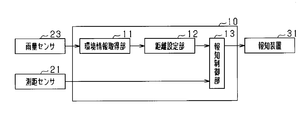
- the driving support apparatus 10 is mounted on a vehicle that is a moving body, detects an object existing around the vehicle, and notifies the driver of the vehicle of the approach between the vehicle and the object. .
- the driving support device 10 is a computer including a CPU, a ROM, a RAM, an I / O, and the like.
- the CPU implements each function by executing a program installed in the ROM.
- the driving support device 10 is connected with a distance measuring sensor 21 and an illuminance sensor 22 as sensor devices for inputting various types of detection information.
- the distance measuring sensor 21 is an ultrasonic sensor, for example, and has a function of transmitting an ultrasonic wave of 20 to 100 kHz as an exploration wave and a function of receiving an exploration wave reflected from an object as a reflected wave.
- the distance sensor 21 has a threshold value of the amplitude of the reflected wave. When the distance sensor 21 receives a reflected wave having an amplitude equal to or larger than the threshold value, the transmission time of the exploration wave and the reception time of the reflected wave are used. Then, the distance to the object is obtained, and the distance is input to the driving support device 10 as the detection distance.
- the illuminance sensor 22 is a sensor that detects the illuminance outside the vehicle. Specifically, the illuminance sensor 22 includes a photodiode. The photodiode generates a current by receiving light, and the generated current increases as the illuminance increases. The current value is detected, and the current value is converted into an illuminance value and input to the driving support device 10.
- the environment information acquisition unit 11 included in the driving support device 10 acquires illuminance from the illuminance sensor 22 as information indicating the environment around the vehicle, and inputs the illuminance value to the distance setting unit 12.
- the notification distance setting unit sets a notification distance used for comparison with the detection distance. Specifically, if the illuminance value acquired from the environment information acquisition unit 11 is greater than a predetermined value, the first distance is set as the notification distance, and if the illuminance value is equal to or less than the predetermined value, the first notification distance is set. A second distance that is larger than the distance is set. The first distance and the second distance are predetermined values.
- the notification control unit 13 compares the notification distance acquired from the distance setting unit 12 with the detection distance acquired from the distance measuring sensor 21. If the detection distance is smaller than the notification distance, it means that the distance between the vehicle and the object is shortened, and therefore the notification device 31 is instructed to perform notification.
- the notification device 31 is a device that notifies the driver that the distance between the vehicle and the object has approached. Specifically, as the notification device 31, a speaker and a display device provided on the instrument panel are used. When a notification instruction is received from the notification control unit 13 of the driving support device 10, The driver is notified of the approach to the object by performing at least one of the light emission displays by the display device.
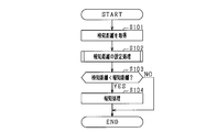
- step S101 a detection distance that is a distance to an object is acquired from the distance measuring sensor 21. At this time, if an object is not detected, information indicating that may be acquired. Then, it progresses to step S102 and the process which sets alerting
- step S102 If the notification distance is set in step S102, the process proceeds to step S103, and it is determined whether or not the detection distance is smaller than the notification distance. If an affirmative determination is made in step S103, that is, if the detection distance is smaller than the notification distance, the process proceeds to step S104, and a notification process for operating the notification device 31 is performed. Then, a series of processing ends. On the other hand, if a negative determination is made in step S103, that is, if the detected distance is equal to or greater than the notification distance, the distance between the vehicle and the object is sufficiently far away and there is no need for notification, so the series of processing ends.
- step S201 the illuminance is acquired from the illuminance sensor 22. Subsequently, in step S202, it is determined whether or not the illuminance is greater than a predetermined value. At this time, the predetermined value to be compared with the illuminance is a predetermined value. If a positive determination is made in step S202, that is, if the illuminance is greater than a predetermined value, the process proceeds to step S203, and the first distance is set as the notification distance. If a negative determination is made in step S202, that is, if the illuminance is less than or equal to a predetermined value, the process proceeds to step S204, and a second distance that is larger than the first distance is set as the notification distance. If the notification distance is set in step S203 or step S204, the subroutine processing is terminated.
- the driving support device 10 has the following effects.
- ⁇ The smaller the illuminance value acquired from the illuminance sensor 22, the darker the vehicle is, so the driver's visual range is narrowed. And when a driver
- the environment information acquired by the environment information acquisition unit 11 is different from that of the first embodiment.
- the configuration of the driving support apparatus 10 according to the present embodiment will be described with reference to FIG.
- the driving support device 10 acquires rainfall as environmental information.
- the rain sensor 23 is attached to the windshield of the vehicle, and the environment information acquisition unit 11 of the driving support device 10 acquires the rain detected by the rain sensor 23 as environment information.
- the rain sensor 23 includes a light emitting diode and a photodiode.
- the mounting angle of the light emitting diode and the photodiode is set so that the light emitted from the light emitting diode is totally reflected on the outer surface of the windshield and enters the photodiode. If raindrops adhere to the outer surface of the windshield, the light is refracted outward on the outer surface of the glass. As a result, as the amount of raindrops adhering to the outer surface of the windshield increases, the light incident on the photodiode decreases. Based on this principle, rainfall is estimated.
- the distance setting unit 12 sets the detection distance to the second distance when the rainfall acquired from the environment information acquisition unit 11 is greater than a predetermined value. On the other hand, when the rainfall is below a predetermined value, the detection distance is set to the first distance.
- the rain sensor 23 reacts in the same manner as in the case of raindrops even when dirt is attached to the windshield. Since the driver's field of view is blocked if the windshield is dirty, the notification distance is set in the same manner as when there is a lot of rain.
- the degree of cloudiness on the inner surface of the windshield can be determined. If the windshield is fogged, the driver's field of view is blocked, so the notification distance may be changed by determining the fog on the inner surface of the windshield.
- the driving support apparatus 10 according to the present embodiment has the following effects in addition to the effects similar to the effects achieved by the driving support apparatus 10 according to the first embodiment.
- Raindrops attached to the windshield increase as the amount of rain increases, and the visibility of the driver is reduced. Moreover, if there is much rainfall, the frequency
- the rainfall is detected by the rainfall sensor 23, and if the acquired rainfall is greater than a predetermined value, the notification distance is set to the second distance, and the notification device 31 is activated earlier. Thereby, in a situation where the driver's visual recognition range is likely to be narrowed, the notification function can be prevented from being deactivated by operating the notification earlier.
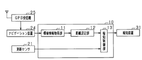
- the environment information acquired by the environment information acquisition unit 11 is different from that of the first embodiment.
- the configuration of the driving support device 10 according to the present embodiment will be described with reference to FIG.
- the vehicle includes a navigation device 24 that is a map display device and a GPS receiver 25 that is a position acquisition device that acquires the current position of the vehicle.
- the navigation device 24 stores map information in a hard disk drive provided therein, and displays a map based on the map information, the current position of the vehicle acquired from the GPS receiver 25, and the like on the display unit. Note that the specific configuration of the navigation device 24 is a known one, and a specific description thereof will be omitted.
- the map information possessed by the navigation device 24 includes a road type including information indicating the road width and road type, an intersection type including information indicating the presence or absence of traffic lights at the intersection, and the like.
- the driving support apparatus 10 acquires map information in the vicinity of the current position as environment information.
- the environment information acquisition unit 11 of the driving support device 10 acquires an intersection type located near the current position, for example, within a predetermined distance.
- the distance setting unit 12 sets the notification distance to the second distance when the intersection type acquired by the environment information acquisition unit 11 indicates that the intersection has poor visibility.
- criteria for judging that the intersection is poor in visibility it is an intersection where no traffic lights are provided, an intersection where roads whose width is smaller than a predetermined value intersect, and there is a building at a corner What is necessary is just to use that it is an intersection.
- the driving support device 10 according to the present embodiment has an effect similar to the effect of the driving support device 10 according to the first embodiment.
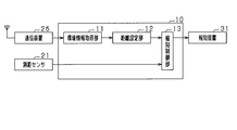
- the environment information acquired by the environment information acquisition unit 11 is different from that of the first embodiment.
- the configuration of the driving support device 10 according to the present embodiment will be described with reference to FIG.
- the vehicle is provided with a communication device 26 that acquires information from outside the vehicle via a wireless communication line.
- the communication device 26 may be provided in advance in the vehicle, or a mobile terminal or the like owned by the driver may be connected to the vehicle by wire or wirelessly.
- the communication device 26 acquires information on air pollution around the vehicle. Specifically, the concentration of particulate matter floating in the atmosphere or the concentration of photochemical smog floating in the atmosphere is acquired.
- Information regarding air pollution acquired by the communication device 26 is input to the vehicle control device, and the environment information acquisition unit 11 acquires the information regarding air pollution as environment information.
- the environment information acquisition unit 11 transmits the acquired environment information to the distance setting unit 12.
- the distance setting unit 12 sets the notification distance to the second distance when the information on air pollution acquired by the environment information acquisition unit 11 indicates that the driver's viewing range is narrow, for example, when the concentration is equal to or greater than a predetermined value. Set to.
- the information acquired by the communication device 26 is not limited to information related to air pollution, and other information may be acquired, for example.
- the weather near the current position of the vehicle is acquired, and the weather may be used as environment information.
- the notification distance can be set as in the second embodiment.
- the driving support apparatus 10 according to the present embodiment has an effect similar to that of the first embodiment.
- part of the processing executed by the distance setting unit 12 is different from that of the first embodiment. Note that the configuration of the driving support device 10 is the same as that of the first embodiment, and a specific description thereof will be omitted.
- FIG. 7 it is assumed that the vehicle is traveling during the daytime in fine weather.
- the illuminance is larger than a predetermined value, and the notification distance is set to the first distance. If the vehicle enters the tunnel, the illuminance measured by the illuminance sensor 22 decreases. If the illuminance falls below a predetermined value at time t1, the notification distance is set to a second distance that is greater than the first distance.
- the illuminance increases, and at time t2, the illuminance becomes larger than a predetermined value.
- the visual recognition range becomes narrow until the driver's eyes get used to the brightness. That is, even if the illuminance increases, the driver's visible range remains narrow.
- the state in which the notification distance is the second distance is maintained from time t2 to time t3 after a predetermined time has elapsed. That is, when the illuminance changes brighter and the notification distance is made smaller based on the change in illuminance, it can be said that the notification distance before the change in illuminance is maintained for a predetermined period. Then, the notification distance is set as the first distance at time t3.
- FIG. 8 shows a subroutine of step S102 in FIG.
- the illuminance is acquired in step S301, and in the subsequent step S302, it is determined whether or not the illuminance is greater than a predetermined value. If a negative determination is made in step S302, that is, if the illuminance is less than or equal to a predetermined value, the process proceeds to step S303.
- the counter value C is set to zero. This counter value C is used to measure the time when the notification distance is the second distance when the illuminance changes from a state below the predetermined value to a state larger than the predetermined value.
- the second distance is set as the notification distance, and the subroutine processing is terminated.
- step S302 If an affirmative determination is made in step S302, that is, if the illuminance is greater than a predetermined value, the process proceeds to step S305, where it is determined whether or not the counter value C is the maximum value Cmax. This maximum value Cmax indicates the length of time during which the notification distance is kept at the second distance, and is a predetermined value. If a negative determination is made in step S305, that is, if the counter value C is smaller than the maximum value Cmax, the process proceeds to step S306, where the counter value C is added. In the subsequent step S304, the second distance is set as the notification distance, and the subroutine processing is terminated.
- step S305 determines whether the counter value C is the maximum value Cmax, a sufficient time has passed since the illuminance is greater than the predetermined value. If an affirmative determination is made in step S305, that is, if the counter value C is the maximum value Cmax, a sufficient time has passed since the illuminance is greater than the predetermined value, so the process proceeds to step S307, and the notification distance is reached.
- the first distance is set as follows. Then, the subroutine processing ends.
- the driving support apparatus 10 according to the present embodiment has the following effects in addition to the effects exhibited by the driving support apparatus 10 according to the first embodiment.
- the notification distance is changed from the second distance to the first distance after a lapse of a predetermined time after the illuminance changes from a state below the predetermined value to a state larger than the predetermined value.
- the notification control unit 13 selects one of a first notification mode and a second notification mode for performing a notification different from the first notification mode as a notification mode, and gives an instruction to the notification device 31. More specifically, in the first notification mode and the second notification mode, the light emission display by the display device is common to the first notification mode, and the notification using the speaker is the first notification mode. Is done at a louder volume. That is, it can be said that the second notification mode is a notification that is easier for the driver to recognize than the first notification mode.
- step S401 a detection distance that is a distance to an object is acquired from the distance measuring sensor 21. Then, it progresses to step S402 and the process which sets alerting
- step S402 one of the processes shown in FIG. 3 of the first embodiment and the process shown in FIG. 8 of the fifth embodiment is performed.
- step S404 determines whether or not the notification distance is set to the second distance. If an affirmative determination is made in step S406, that is, if the detected distance is smaller than the first distance, the process proceeds to step S405, and the notification process is performed in the second notification mode. Then, a series of processing ends.
- the notification is performed in the second notification mode. It becomes.
- the reference distance since the notification is performed in the second notification mode if the detection distance is less than the first distance regardless of the setting state of the notification distance, the reference distance may be referred to for the first distance.
- the driving support apparatus 10 according to the present embodiment has the following effects in addition to the effects exhibited by the driving support apparatus 10 according to the first embodiment.
- the notification control unit 13 acquires the vehicle speed, which is the moving speed, from the vehicle speed sensor 27. If the acquired vehicle speed is zero, the notification control unit 13 notifies the notification device 31 even when the detection distance is smaller than the notification distance. No instructions are given. By carrying out like this, it can suppress that the alerting
- the notification device 31 is operated for a distant object, which can be said to be an unnecessary operation. Therefore, when the vehicle speed is zero, the notification device 31 is activated on the condition that the detection distance is less than the first distance regardless of whether the notification distance is set to the first distance or the second distance. It is good also as what makes it.
- the driving support device 40 acquires a relative speed between the vehicle and the object in addition to the distance between the vehicle and the object from the distance measuring sensor 21. And when the relative speed of a vehicle and an object is maintained, it is determined whether the alerting
- the environment information acquisition unit 41 acquires the illuminance value from the illuminance sensor 22 and inputs the illuminance value to the timing setting unit 42 as in the first embodiment.
- the timing setting unit 42 sets a notification timing that is a timing for starting notification by the notification device 31 and an operation timing that is a timing for starting the operation of the brake device 32 as timings used for comparison with the collision time. Note that the larger the notification timing is, the faster the notification device is operated. That is, the greater the notification timing, the greater the detection distance for operating the notification device. Therefore, the greater the notification timing, the larger the notification distance used in the processing in the first to seventh embodiments. It can be said.
- the collision time calculation unit 43 calculates the collision time by dividing the detection distance acquired from the distance measuring sensor 21 by the relative speed with the object acquired by the distance measuring sensor 21.
- the notification control unit 44 acquires the notification timing from the timing setting unit 42. That is, one of the first timing and the second timing set as the notification timing is acquired. Further, the collision time is acquired from the collision time calculation unit 43. And if the collision time is less than the set notification timing, a command is sent to the notification device 31.
- the braking control unit 45 acquires the operation timing from the timing setting unit 42 and acquires the collision time from the collision time calculation unit 43. If the collision time is less than the operation timing of the brake device 32, the brake device 32 is instructed.
- the driving support device 40 according to the present embodiment has an effect similar to that of the driving support device 10 according to the first embodiment.
- an ultrasonic sensor is used as the distance measuring device.
- the distance measuring device is not limited to the ultrasonic sensor, and another device such as a radar device or a stereo camera may be used.
- the illuminance sensor 22 that measures the illuminance using a photodiode is exemplified, but means for acquiring the illuminance is not limited to this.
- a phototransistor or a photoresistor may be employed. It is also common to mount a camera on a vehicle and use the camera as means for detecting the positions of surrounding objects. Therefore, it is good also as what acquires illumination intensity based on the image acquired from the camera with which the vehicle is mounted.
- the notification distance when the illuminance is less than or equal to a predetermined value, the notification distance is set to a second value that is a larger value.
- a predetermined value to be compared with the illuminance a first predetermined value and a second predetermined value larger than the first predetermined value may be provided.
- the illuminance during the daytime in fine weather is set to be between the first predetermined value and the second predetermined value.
- the notification distance is set as the second distance. In this way, when the illuminance is excessively large and the driver's viewing range is likely to be narrowed, such as during backlighting, the notification distance can be set large.
- the illuminance is measured by the illuminance sensor 22.
- the driver recognizes that the illuminance is low when the driver performs an operation of turning on the headlight of the vehicle. Therefore, the operation state of the headlight by the driver may be set as environment information indicating the illuminance, and the illuminance may be determined to be smaller than a predetermined value if an operation of turning on the headlight is performed.
- the rain sensor 23 is also provided on the inner side of the windshield, and the process of determining the fog on the inner side of the windshield by the rain sensor 23 is exemplified.
- fogging of the windshield is caused by the humidity inside the vehicle and the temperature difference between the inside and outside of the vehicle. Therefore, these pieces of information may be acquired as environmental information to determine whether the windshield is fogged.
- the process of determining the rainfall, the fog on the inside of the windshield, and the dirt on the windshield by the rain sensor 23 is exemplified.
- a camera may be mounted inside the vehicle, and the amount of rain, fogging inside the windshield, and dirt on the windshield may be determined based on an image acquired from the camera.
- the rainfall is detected by the rainfall sensor 23.
- the driver increases the operating speed of the wiper. Therefore, the operation state of the wiper by the driver may be acquired as environmental information indicating the amount of rain.
- an intersection type is acquired as map information, and a notification distance is set based on the intersection type.
- the notification distance may be set based on other map information.
- the illumination intensity is low and the viewing range is narrowed.
- the viewing range is narrowed. Therefore, when the position of the vehicle is in a tunnel, an indoor parking lot, or the like, the notification distance may be set to the second distance.
- -It is good also as what acquires the map by communication while adding the function of position acquisition apparatuses, such as a GPS receiver, to the communication apparatus 26 in 4th Embodiment. By doing so, it is possible to perform processing equivalent to that of the third embodiment using the communication device 26.
- the notification distance is changed after a predetermined time has elapsed from the time of the change.
- the volume or the like in the notification may be gradually increased as the detection distance becomes smaller.
- the volume when switching between the first notification mode and the second notification mode as in the sixth embodiment, when switching from the first notification mode to the second notification mode, The volume may be set so as to increase gradually.
- the notification by the notification device 31 when the vehicle speed is zero, the notification by the notification device 31 is performed. In this regard, if the driver intends to start the vehicle even if the vehicle speed is zero, notification should be performed. Therefore, when the vehicle is a vehicle equipped with an automatic transmission, if the drive range or the reverse range is selected, the notification is made, and if the neutral range or the reverse range is selected, the notification is not made.
- the collision time is calculated by dividing the detection distance by the vehicle speed.
- the driving assistance device 40 may also acquire the acceleration of the vehicle, and calculate the collision time using the detection distance, the vehicle speed, and the acceleration.
- the relative speed between the vehicle and the object may be acquired instead of the vehicle speed, and the collision time may be calculated by dividing the detection distance by the relative speed.
- relative acceleration may also be used.
- the notification distance may be set to be larger when the first embodiment and the second embodiment are combined and the illuminance is small and the rainfall is large.
- the notification distance is set to one of the first distance and the second distance.
- the notification distance may be set to three or more values according to the environmental information. Further, as in the first embodiment, if the environment information is indicated by a numerical value, it may be changed in proportion to the numerical value.
- the driving support devices 10 and 40 are mounted on the vehicle, but may be mounted on a moving body other than the vehicle and notify the driver of the moving body.
Abstract
運転支援装置(10,40)は、移動体に設けられ、その移動体の運転者に対して前記移動体と周囲の物体との接近を報知するものである。この運転支援装置は、前記移動体の外部及び内部の少なくとも一方の環境に基づいて求められる情報であり、且つ、前記運転者の視認範囲の広さを示す情報である環境情報を取得する環境情報取得部(11,41)と、前記環境情報が示す前記視認範囲が狭いほど、前記報知を行う距離である報知距離を大きくする距離設定部(12,42)と、前記移動体と前記物体との距離を検知距離として取得し、その検知距離が前記報知距離よりも小さい場合に前記運転者へ報知を行う報知制御部(13,44)と、を備える。
Description
本出願は、2016年4月21日に出願された日本出願番号2016-085382号に基づくもので、ここにその記載内容を援用する。
本開示は、移動体の運転者による運転を支援する運転支援装置に関する。
従来、超音波センサ等の測距センサを用いて移動体の周囲に存在する物体との距離を検知し、その距離に応じて、移動体の物体への接近を運転者に報知を行う運転支援装置が実現されている。
このような運転支援装置として、特許文献1に記載の運転支援装置がある。特許文献1に記載の運転支援装置では、車速に応じて報知を行う距離を変更している。
運転者に対して物体との接近の報知を行う場合、報知を行う必要があるにも係らず報知が行われない不作動を抑制する必要がある。このとき、報知を開始する距離をより大きく設定することにより、不作動を抑制することができる。一方、報知を開始する距離をより大きく設定すれば、運転者が車両と物体との接近に気付いているにもかかわらず報知を行うことが多くなり、運転者はその報知を煩わしく感ずる。すなわち、報知する必要が無いにもかかわらず、報知が行われる不要作動となる。したがって、運転者に対して、移動体と物体との接近を報知する場合、不作動の抑制と不要作動の抑制とを両立させる必要がある。
本開示は、上記課題を解決するためになされたものであり、その主たる目的は、報知装置を適切に作動させることができる運転支援装置を提供することにある。
本開示は、移動体に設けられ、その移動体の運転者に対して移動体と周囲の物体との接近を報知する運転支援装置であって、移動体の周囲及び内部の少なくとも一方の環境に基づいて求められる情報であり、且つ、運転者の視認範囲の広さを示す情報である環境情報を取得する環境情報取得部と、環境情報が示す視認範囲が狭いほど、報知を行う距離である報知距離を大きくする距離設定部と、移動体と物体との距離が報知距離よりも小さい場合に運転者へ報知を行う報知制御部と、を備える。
移動体の運転中において、運転者の視認範囲が狭い場合には、運転者は、移動体の周囲の物体への接近に気づきにくい。そのため、物体との接近の報知をより早期に行うことにより、報知機能の不作動を抑制することができる。一方、運転者に対して、移動体の周囲の物体への接近をより早期に行うことは、報知機能の不要作動の要因ともなり得る。上記構成では、運転者の視認範囲が、移動体の周囲及び内部の少なくとも一方の環境によって変化する点に着目し、視認範囲の広さを示す情報を環境情報として取得している。そして、その環境情報が示す視認範囲が狭いほど、報知距離を大きくしているため、運転者の視認範囲が狭い環境では、物体との接近の報知をより早期に行うことができる。これにより、報知機能の不作動の抑制と不要作動の抑制とを両立することができる。
本開示についての上記目的およびその他の目的、特徴や利点は、添付の図面を参照しながら下記の詳細な記述により、より明確になる。その図面は、
図1は、第1実施形態に係る運転支援装置の構成図であり、
図2は、第1実施形態に係る運転支援装置が実行する処理を示すフローチャートであり、
図3は、第1実施形態における報知距離の設定処理を示すサブルーチンであり、
図4は、第2実施形態に係る運転支援装置の構成図であり、
図5は、第3実施形態に係る運転支援装置の構成図であり、
図6は、第4実施形態に係る運転支援装置の構成図であり、
図7は、第5実施形態に係る運転支援装置が実行する処理を示すタイムチャートであり、
図8は、第5実施形態における報知距離の設定処理を示すサブルーチンであり、
図9は、第6実施形態に係る運転支援装置が実行する処理を示すフローチャートであり、
図10は、第7実施形態に係る運転支援装置の構成図であり、
図11は、第8実施形態に係る運転支援装置の構成図である。
以下、本開示の実施形態について図に基づいて説明する。なお、以下の各実施形態相互において、互いに同一もしくは均等である部分には、図中、同一符号を付してある。
<第1実施形態>
本実施形態に係る運転支援装置10は、移動体である車両に搭載され、車両の周囲に存在する物体を検知し、車両と物体との接近をその車両の運転者へと報知するものである。
本実施形態に係る運転支援装置10は、移動体である車両に搭載され、車両の周囲に存在する物体を検知し、車両と物体との接近をその車両の運転者へと報知するものである。
図1において、運転支援装置10は、CPU、ROM、RAM、I/O等を備えたコンピュータである。この運転支援装置10は、CPUが、ROMにインストールされているプログラムを実行することで各機能を実現する。
運転支援装置10には、各種の検知情報を入力するセンサ装置として、測距センサ21、及び照度センサ22が接続されている。
測距センサ21は、例えば超音波センサであり、20~100kHzの超音波を探査波として送信する機能と、物体から反射した探査波を反射波として受信する機能とを有している。測距センサ21には反射波の振幅の閾値が設定されており、閾値以上の振幅の反射波を測距センサ21が受信した場合に、探査波の送信時刻と反射波の受信時刻とを用いて、物体との距離を求め、その距離を検知距離として運転支援装置10へ入力する。
照度センサ22は、車両の外部の照度を検知するセンサである。具体的には、照度センサ22はフォトダイオードを備えている。フォトダイオードは、受光によって電流を発生させるものであり、照度が大きくなるほど、発生する電流も大きくなる。その電流の値を検出し、電流の値を照度の値へと変換して運転支援装置10へと入力する。
運転支援装置10が備える環境情報取得部11は、車両の周囲の環境を示す情報として照度を照度センサ22から取得し、その照度の値を距離設定部12へと入力する。報知距離設定部は、検知距離との比較に用いる報知距離を設定する。具体的には、環境情報取得部11から取得した照度の値が所定値よりも大きければ、報知距離として第1距離を設定し、照度の値が所定値以下であれば、報知距離として第1距離よりも大きい値である第2距離を設定する。この第1距離及び第2距離は、予め定められた値である。このようにして報知距離を設定することで、照度が所定値以下であれば、そうでない場合よりも早いタイミングで、報知処理を行うこととなる。
報知制御部13は、距離設定部12から取得した報知距離と、測距センサ21から取得した検知距離とを比較する。そして、検知距離が報知距離よりも小さければ、車両と物体との距離が縮まっていることを意味するため、報知装置31に対して、報知を行う旨の指示を行う。
報知装置31は、運転者に対して車両と物体との距離が接近したことを報知する装置である。具体的には、報知装置31として、スピーカと、インストルメントパネルに設けられた表示装置とを用いており、運転支援装置10の報知制御部13から報知の指示を受ければ、スピーカによる報知音と、表示装置による発光表示の少なくとも一方を行うことにより、運転者に対して物体との接近を報知する。
続いて、本実施形態に係る運転支援装置10が実行する一連の処理について、図2のフローチャートを参照して説明する。図2のフローチャートで示す処理は、所定の周期毎に繰り返し実行される。
まずステップS101にて、測距センサ21から、物体との距離である検知距離を取得する。このとき、物体を検知しなければ、その旨を示す情報を取得するものとすればよい。続いて、ステップS102へ進み、報知距離を設定する処理を行う。このステップS102の具体的処理については、後述する。
ステップS102で報知距離が設定されれば、ステップS103へ進み、検知距離が報知距離よりも小さいか否かを判定する。ステップS103にて肯定判定すれば、すなわち、検知距離が報知距離よりも小さければ、ステップS104へ進み、報知装置31を作動させる報知処理を行う。そして、一連の処理を終了する。一方、ステップS103にて否定判定すれば、すなわち、検知距離が報知距離以上であれば、車両と物体との距離は十分に離れており報知の必要がないため、そのまま一連の処理を終了する。
図2のフローチャートにおけるステップS102の報知距離の設定処理に係るサブルーチンについて、図3を参照して説明する。
まずステップS201にて、照度センサ22から照度を取得する。続いて、ステップS202にて、照度が所定値よりも大きいか否かを判定する。このとき、照度と比較する所定値は、予め定められた値である。ステップS202にて肯定判定すれば、すなわち照度が所定値よりも大きければ、ステップS203へ進み、報知距離として第1距離を設定する。ステップS202にて否定判定すれば、すなわち照度が所定値以下であれば、ステップS204へ進み、報知距離として第1距離よりも大きい値である第2距離を設定する。ステップS203又はステップS204で報知距離が設定されれば、サブルーチンの処理を終了する。
上記構成により、本実施形態に係る運転支援装置10は、以下の効果を奏する。
・照度センサ22から取得した照度の値が小さいほど、車両の周囲は暗いため、運転者の視認範囲は狭まる。そして、運転者の視認範囲が狭い場合には、運転者は、車両と周囲の物体との接近に気づきにくい。そのため、環境情報として取得した照度の値が所定値よりも小さい場合に、物体との接近の報知をより早期に行うことにより、報知機能の不作動を抑制することができる。加えて、照度の値が所定値よりも大きく運転者の視認範囲が広いと推測できる状況において、報知距離を第1距離に設定することにより、報知装置31の不要作動を抑制することができる。したがって、報知装置31の不作動の抑制と不要作動の抑制を両立することができる。
<第2実施形態>
本実施形態に係る運転支援装置10では、環境情報取得部11が取得する環境情報が、第1実施形態と異なっている。本実施形態に係る運転支援装置10の構成を、図4を参照して説明する。
本実施形態に係る運転支援装置10では、環境情報取得部11が取得する環境情報が、第1実施形態と異なっている。本実施形態に係る運転支援装置10の構成を、図4を参照して説明する。
本実施形態に係る運転支援装置10は、環境情報として雨量を取得する。具体的には、車両のフロントガラスには雨量センサ23が取り付けられており、運転支援装置10の環境情報取得部11は、雨量センサ23が検知した雨量を環境情報として取得する。
雨量センサ23は、発光ダイオードとフォトダイオードとを備えている。発光ダイオード及びフォトダイオードの取り付け角度は、発光ダイオードから発せられた光がフロントガラスの外面で全反射してフォトダイオードへ入射するように、設定されている。フロントガラスの外面に雨粒が付着すれば、ガラスの外面で光が外側へと屈折する。これにより、フロントガラスの外面に付着した雨粒の量が多くなるほど、フォトダイオードへ入射する光が小さくなる。この原理により、雨量を推定する。
距離設定部12は、環境情報取得部11から取得した雨量が所定値よりも多い場合、検知距離を第2距離に設定する。一方、雨量が所定値以下である場合には、検知距離を第1距離に設定する。
なお、雨量センサ23は、フロントガラスに汚れが付着している場合にも、雨粒の場合と同様に反応する。フロントガラスが汚れていれば運転者の視界は遮られるため、雨量が多い場合と同様に報知距離を設定する。
ところで、雨量センサ23をフロントガラスの内面で光が全反射するように設けた場合、フロントガラスの内面の曇りの程度を判定することができる。フロントガラスが曇っていれば運転者の視界は遮られるため、フロントガラスの内面の曇りを判定して報知距離を変更するものとしてもよい。
上記構成により、本実施形態に係る運転支援装置10は、第1実施形態に係る運転支援装置10が奏する効果に準ずる効果に加えて、以下の効果を奏する。
・雨量が多いほどフロントガラスに付着する雨粒が増し、運転者の視認範囲は狭まる。また、雨量が多ければ、ワイパの時間当たりの往復回数が増加し、運転者の視認範囲は狭まる。本実施形態では、雨量センサ23により雨量を検出し、その取得した雨量が所定値よりも多ければ、報知距離を第2距離に設定し、より早期に報知装置31を作動させるものとしている。これにより、運転者の視認範囲が狭まっている可能性が高い状況において、より早期に報知を作動させることにより、報知機能の不作動を抑制することができる。
<第3実施形態>
本実施形態に係る運転支援装置10では、環境情報取得部11が取得する環境情報が、第1実施形態と異なっている。本実施形態に係る運転支援装置10の構成を、図5を参照して説明する。
本実施形態に係る運転支援装置10では、環境情報取得部11が取得する環境情報が、第1実施形態と異なっている。本実施形態に係る運転支援装置10の構成を、図5を参照して説明する。
車両には、地図表示装置であるナビゲーション装置24と、車両の現在位置を取得する位置取得装置であるGPS受信機25とが備えられている。ナビゲーション装置24は、内部に設けられたハードディスクドライブに地図情報を格納しており、その地図情報に基づく地図や、GPS受信機25から取得した車両の現在位置等を表示部に表示する。なお、ナビゲーション装置24の具体的な構成については、公知のものであるため、具体的な説明は省略する。
ナビゲーション装置24が有する地図情報には、道路の幅や道路の種類を示す情報を含む道路種別、交差点における信号機の有無を示す情報等を含む交差点種別等が含まれている。
本実施形態に係る運転支援装置10は、環境情報として、現在位置の近傍の地図情報を取得する。具体的には、運転支援装置10の環境情報取得部11は、現在位置の近傍、例えば所定距離内に位置する交差点種別を取得する。距離設定部12は、環境情報取得部11が取得した交差点種別が見通しの悪い交差点であることを示す場合には、報知距離を第2距離に設定する。なお、見通しの悪い交差点であると判定する基準としては、信号機の設けられていない交差点であること、幅が所定値よりも小さい道路どうしが交差する交差点であること、角に建造物が存在する交差点であること等を用いればよい。
上記構成により、本実施形態に係る運転支援装置10は、第1実施形態に係る運転支援装置10が奏する効果に準ずる効果を奏する。
<第4実施形態>
本実施形態に係る運転支援装置10では、環境情報取得部11が取得する環境情報が、第1実施形態と異なっている。本実施形態に係る運転支援装置10の構成を、図6を参照して説明する。
本実施形態に係る運転支援装置10では、環境情報取得部11が取得する環境情報が、第1実施形態と異なっている。本実施形態に係る運転支援装置10の構成を、図6を参照して説明する。
車両には、無線通信回線を介して車両外部から情報を取得する通信装置26が設けられている。この通信装置26は、車両に予め備えられているものであってもよいし、運転者が所有する携帯端末等を車両に有線又は無線で接続ものとしてもよい。
通信装置26は、車両周囲の大気汚染に関する情報を取得する。具体的には、大気中に浮遊する粒子状物質の濃度、又は、大気中に浮遊する光化学スモッグの濃度を取得する。
通信装置26が取得した大気汚染に関する情報は、車両制御装置へ入力され、環境情報取得部11は、その大気汚染に関する情報を環境情報として取得する。環境情報取得部11は取得した環境情報を距離設定部12へと送信する。距離設定部12は、環境情報取得部11が取得した大気汚染に関する情報が、運転者の視認範囲が狭いことを示す場合、例えば濃度が所定値以上である場合には、報知距離を第2距離に設定する。
なお、本実施形態において、通信装置26が取得する情報は大気汚染に関する情報に限られず、例えば、他の情報を取得するものとしてもよい。具体的には、車両の現在位置近傍の天候を取得し、その天候を環境情報としてもよい。この場合には、天候として降雨量を取得すれば、第2実施形態と同様に報知距離を設定することができる。また、天候として霧に関する情報を取得してもよい。
上記構成により、本実施形態に係る運転支援装置10は、第1実施形態に準ずる効果を奏する。
<第5実施形態>
本実施形態に係る運転支援装置10では、距離設定部12が実行する処理の一部が、第1実施形態と異なっている。なお、運転支援装置10の構成は第1実施形態と同様であるため、具体的な説明を省略する。
本実施形態に係る運転支援装置10では、距離設定部12が実行する処理の一部が、第1実施形態と異なっている。なお、運転支援装置10の構成は第1実施形態と同様であるため、具体的な説明を省略する。
まず、図7を参照して、本実施形態に係る運転支援装置10が実行する処理の概要を説明する。なお、図7において、車両は晴天時の昼間に走行しているものとする。車両がトンネルの外部を走行している場合、照度は所定値よりも大きい値となり、報知距離を第1距離に設定する。車両がトンネルへ進入すれば、照度センサ22が計測する照度が低下し、時刻t1で照度が所定値以下となれば、報知距離を第1距離よりも大きい距離である第2距離に設定する。
車両がトンネル内を走行し、トンネルの出口へと近づけば照度は増加し、時刻t2で照度は所定値よりも大きい値となる。このとき、照度は急激に増加するため、運転者の目は明るさに慣れるまでは視認範囲は狭くなる。すなわち、照度が増加したとしても、運転者の視認範囲は狭いままである。そのため、時刻t2から所定時間経過後の時刻t3までは、報知距離を第2距離とする状態を維持する。すなわち、照度がより明るく変化し、且つ、その照度の変化に基づいて報知距離をより小さくする場合に、照度の変化の前の報知距離を所定期間維持するものであるといえる。そして、時刻t3で報知距離を第1距離とする。
続いて、本実施形態に係る運転支援装置10は実行する報知距離の設定処理について、図8を用いて説明する。なお、図8では、図2におけるステップS102のサブルーチンを示している。
まずステップS301にて照度を取得し、続くステップS302にて、照度が所定値よりも大きいか否かを判定する。ステップS302で否定判定すれば、すなわち照度が所定値以下であれば、ステップS303へ進む。ステップS303では、カウンタ値Cをゼロとする。このカウンタ値Cは、照度が所定値以下の状態から所定値よりも大きい状態へと変化した際に、報知距離を第2距離とする時間の計時に用いられるものである。続くステップS304にて、報知距離として第2距離を設定し、サブルーチンの処理を終了する。
ステップS302にて肯定判定すれば、すなわち照度が所定値よりも大きければ、ステップS305へ進み、カウンタ値Cが最大値Cmaxであるか否かを判定する。この最大値Cmaxは、報知距離を第2距離とする状態を維持する時間の長さを示すものであり、予め定められた値である。ステップS305にて否定判定すれば、すなわち、カウンタ値Cが最大値Cmaxよりも小さければ、ステップS306へ進み、カウンタ値Cの加算を行う。そして、続くステップS304にて報知距離として第2距離を設定し、サブルーチンの処理を終了する。
一方、ステップS305にて肯定判定すれば、すなわちカウンタ値Cが最大値Cmaxであれば、照度が所定値よりも大きくなってから十分な時間が経過しているため、ステップS307へ進み、報知距離として第1距離を設定する。そして、サブルーチンの処理を終了する。
上記構成により、本実施形態に係る運転支援装置10は、第1実施形態に係る運転支援装置10が奏する効果に加えて、以下の効果を奏する。
・車両がトンネルから出た場合等、照度が大きくなった場合には、運転者の目が明るさに慣れるまでに時間がかかり、一時的に視認範囲が狭まる場合がある。本実施形態では、照度が所定値以下の状態から所定値よりも大きい状態へと変化してから所定時間経過後に、報知距離を第2距離から第1距離へと変化させるものとした。これにより、照度が大きくなって一時的に運転者の視認範囲が狭まっている可能性がある場合において、報知距離を第1距離よりも大きい第2距離とすることができる。したがって、運転者の視認範囲の広さに応じた報知距離を設定することができる。
<第6実施形態>
本実施形態に係る運転支援装置10では、報知制御部13が実行する処理の一部が、第1実施形態と異なっている。なお、運転支援装置10の構成は第1実施形態と同様であるため、具体的な説明を省略する。
本実施形態に係る運転支援装置10では、報知制御部13が実行する処理の一部が、第1実施形態と異なっている。なお、運転支援装置10の構成は第1実施形態と同様であるため、具体的な説明を省略する。
報知制御部13は、報知の態様として、第1報知態様と、その第1報知態様と異なる報知を行う第2報知態様とのうちの一方を選択し、報知装置31へと指示を行う。より具体的には、第1報知態様と第2報知態様とでは、表示装置による発光表示は第1報知態様と共通しており、スピーカを用いた報知は、第2報知態様は第1報知態様よりも大きな音量で行うものである。すなわち、第2報知態様は、第1報知態様よりも運転者が認知しやすい報知であるといえる。
本実施形態に係る運転支援装置10が実行する一連の処理について、図9のフローチャートを参照して説明する。図9のフローチャートで示す処理は、所定の周期毎に繰り返し実行される。
まずステップS401にて、測距センサ21から、物体との距離である検知距離を取得する。続いて、ステップS402へ進み、報知距離を設定する処理を行う。このステップS402では、第1実施形態の図3で示した処理、及び第5実施形態の図8で示した処理の一方の処理を行う。
ステップS402で報知距離が設定されれば、ステップS403へ進み、検知距離が報知距離よりも小さいか否かを判定する。ステップS403にて否定判定すれば、すなわち、検知距離が報知距離以上であれば、車両と物体との距離は十分に離れており報知の必要がないため、そのまま一連の処理を終了する。ステップS403にて肯定判定すれば、すなわち、検知距離が報知距離よりも小さければ、ステップS404へ進み、ステップS402で設定した報知距離が第1距離であるか否かを判定する。ステップS404にて肯定判定すれば、すなわち報知距離が第2距離に設定されていれば、ステップS405にて第1報知態様で報知処理を行い、一連の処理を終了する。
一方、ステップS404にて否定判定した場合、すなわち、報知距離が第2距離に設定されている場合、ステップS406へ進み、検知距離が第1距離よりも小さいか否かを判定する。ステップS406にて肯定判定した場合、すなわち検知距離が第1距離よりも小さい場合、ステップS405へ進み、第2報知態様で報知処理を行う。そして一連の処理を終了する。
ステップS406にて否定判定した場合、すなわち検知距離が第1距離以上であり且つ第2距離よりも小さい場合、ステップS407へ進み、第1報知態様で報知処理を行う。そして、一連の処理を終了する。
このように報知制御を行うため、報知距離が第1距離と第2距離とのいずれに設定されていたとしても、検知距離が第1距離を下回れば、第2報知態様で報知が行われることとなる。なお、報知距離の設定状態にかかわらず検知距離が第1距離を下回れば第2報知態様で報知を行うことから、第1距離については基準距離を称することもできる。
上記構成により、本実施形態に係る運転支援装置10は、第1実施形態に係る運転支援装置10が奏する効果に加えて、以下の効果を奏する。
・報知距離として第2距離が設定されている場合、検知距離が報知距離よりも小さくなったとしても、物体との衝突の危険性は低いといえる。本実施形態では、報知距離として第2距離が設定されている場合には、検知距離が第1距離となるまでは、第2報知態様よりも運転者が認知しにくい第1報知態様で報知を行うため、報知距離として第2距離が設定されている場合に過剰な報知が行われる事態を抑制することができる。
<第7実施形態>
本実施形態に係る運転支援装置10は、図10に示すように、車両が備える車速センサ27から車速を取得する点が、上記の各実施形態と異なっている。
本実施形態に係る運転支援装置10は、図10に示すように、車両が備える車速センサ27から車速を取得する点が、上記の各実施形態と異なっている。
報知制御部13は、車速センサ27から移動速度である車速を取得し、取得した車速がゼロであれば、検知距離が報知距離よりも小さい場合でも、報知装置31に対して、報知を行う旨の指示を行わないものとしている。こうすることで、車両の停止時に報知装置31が作動することを抑制することができる。なお、報知装置31は車速を取得することから、速度取得部ということができる。
なお、車速がゼロである場合であっても、その状態から運転者が車両を移動させることがある。このようなとき、物体が近傍に位置していれば、報知したほうが良い場合もある。一方で、報知距離が第2距離に設定されている場合には、遠方の物体に対して、報知装置31を作動させることとなり、不要作動であるといえる。そのため、車速がゼロである場合には、報知距離が第1距離と第2距離とのいずれに設定されていても、検知距離が第1距離未満となることを条件に、報知装置31を作動させるものとしてもよい。
<第8実施形態>
本実施形態に係る運転支援装置40は、図11に示すように、測距センサ21から、車両と物体との距離に加えて、車両と物体との相対速度をも取得する。そして、車両と物体との相対速度が維持された場合に車両と物体とが衝突するまで時間である衝突時間を用いて、報知装置31を作動させるか否かを判定する。また、運転支援装置40は、車両と物体との衝突の危険が高まった場合に、報知装置31に加えてブレーキ装置32を作動させ、衝突の回避又は衝突被害の軽減を行う。
本実施形態に係る運転支援装置40は、図11に示すように、測距センサ21から、車両と物体との距離に加えて、車両と物体との相対速度をも取得する。そして、車両と物体との相対速度が維持された場合に車両と物体とが衝突するまで時間である衝突時間を用いて、報知装置31を作動させるか否かを判定する。また、運転支援装置40は、車両と物体との衝突の危険が高まった場合に、報知装置31に加えてブレーキ装置32を作動させ、衝突の回避又は衝突被害の軽減を行う。
環境情報取得部41は、第1実施形態と同様に、照度センサ22から照度の値を取得し、その照度の値をタイミング設定部42へと入力する。タイミング設定部42は、衝突時間との比較に用いるタイミングとして、報知装置31による報知を開始するタイミングである報知タイミングと、ブレーキ装置32の作動を開始するタイミングである作動タイミングを設定する。なお、報知タイミングが大きな値であるほど、より早く報知装置を作動させることとなる。すなわち、報知タイミングが大きな値であるほど報知装置を作動させる検知距離がより大きくなるため、報知タイミングが大きな値であるほど、第1~第7実施形態における処理で用いた報知距離を大きく設定するということができる。
タイミング設定部42は、報知タイミングとして、第1タイミングと、第1タイミングよりも大きい値である第2タイミングとの一方を設定する。また、作動タイミングは、第1タイミング及び第2タイミングのいずれよりも大きな値に設定される。すなわち、報知装置31の作動タイミングとして第1タイミング及び第2タイミングのいずれが選択されていたとしても、報知装置31が作動してからさらに時間が経過した後に、ブレーキ装置32が作動することとなる。これは、報知装置31の作動によって運転者がブレーキ操作の必要性に気づいてブレーキ操作を行えば、運転支援装置40によるブレーキ装置32の作動制御は必要ないためである。
タイミング設定部42は、環境情報取得部41から取得した照度が所定値よりも大きければ、報知装置31の作動タイミングを第1タイミングに設定し、照度が所定値以下であれば、報知装置31の作動タイミングを第2タイミングに設定する。すなわち、照度が所定値以下であれば、より早期に報知装置31が作動するようにする。
衝突時間算出部43は、測距センサ21から取得した検知距離を、測距センサ21が取得した物体との相対速度で除算することにより、衝突時間を算出する。
報知制御部44は、タイミング設定部42から報知タイミングを取得する。すなわち、報知タイミングとして設定された第1タイミング及び第2タイミングの一方を取得する。また、衝突時間算出部43から衝突時間を取得する。そして、衝突時間が設定された報知タイミングを下回っていれば、報知装置31へ指令を行う。
制動制御部45は、タイミング設定部42から作動タイミングを取得し、衝突時間算出部43から衝突時間を取得する。衝突時間がブレーキ装置32の作動タイミングをも下回っていれば、ブレーキ装置32へ指令を行う。
上記構成により、本実施形態に係る運転支援装置40は、第1実施形態に係る運転支援装置10に準ずる効果を奏する。
<変形例>
・実施形態では、測距装置として超音波センサを用いるものとした。この点、測距装置は超音波センサに限られず、レーダ装置やステレオカメラ等の他の装置を用いるものとしてもよい。
・実施形態では、測距装置として超音波センサを用いるものとした。この点、測距装置は超音波センサに限られず、レーダ装置やステレオカメラ等の他の装置を用いるものとしてもよい。
・第1実施形態等では、照度センサ22としてフォトダイオードを用いて照度を計測するものを例示したが、照度を取得するための手段はこれに限られない。例えば、フォトトランジスタ、フォトレジスタ等を採用してもよい。また、車両にカメラを搭載し、そのカメラを周囲の物体の位置を検知する手段として用いることも一般的に行われている。そのため、車両が搭載しているカメラから取得した画像に基づいて照度を取得するものとしてもよい。
・第1実施形態では、照度が所定値以下である場合に、報知距離をより大きい値である第2距離に設定するものとした。この点、照度と比較する所定値として、第1所定値と、第1所定値よりも大きい第2所定値とを設けるものとしてもよい。この場合には、晴天時の昼間の照度が第1所定値と第2所定値との間となるようにする。そして、照度が第1所定値以下である場合、及び第2所定値以上である場合に、報知距離を第2距離とする。こうすることで、逆光時等のような、照度が過剰に大きく運転者の視認範囲が狭まる可能性が高い場合に、報知距離を大きく設定することができる。
・第1実施形態等では、照度センサ22により照度を計測するものとした。この点、運転者による車両のヘッドライトを点灯させる操作が行われた場合、運転者は照度が小さくなっていると認識しているといえる。そのため、運転者によるヘッドライトの操作状態を照度を示す環境情報とし、ヘッドライトを点灯させる操作が行われば、照度が所定値よりも小さいと判定するものとしてもよい。
・第2実施形態では、雨量センサ23をフロントガラスの内側にも設け、その雨量センサ23によりフロントガラスの内側の曇りを判定する処理を例示した。この点、フロントガラスの曇りは、車両内部の湿度や、車両の内部と外部との気温差により生ずるものである。そのため、これらの情報を環境情報として取得し、フロントガラスの曇りを判定してもよい。
・第2実施形態では、雨量センサ23により、雨量、フロントガラスの内側の曇り、及びフロントガラスの汚れを判定する処理を例示した。この点、車両の内部にカメラを搭載し、そのカメラから取得した画像に基づいて、雨量、フロントガラスの内側の曇り、及びフロントガラスの汚れを判定してもよい。
・第2実施形態では、雨量センサ23により、雨量を検出するものとした。この点、雨量が多くなるほど、運転者はワイパの作動速度を早くすることから、運転者によるワイパの操作状態を雨量を示す環境情報として取得するものとしてもよい。
・実施形態1における照度を取得するための装置として、第3実施形態で示したGPS受信機25を採用してもよい。GPS受信機25から取得した車両の位置の緯度と、車両が備える時計から取得した日付とを取得すれば、その日の日没時刻が求まる。その日没時刻と現在の時刻とを用いれば、照度を推定することができるため、第1実施形態と同様に、照度を用いて報知距離を変更する処理を行うことが可能となる。この場合、第2実施形態で示した雨量センサ23や、第4実施形態で示した通信装置26を同時に用いるものとし、日没時刻で推定した照度と天候とを用いて、報知距離を変更する処理を行うものとしてもよい。
・第3実施形態において、地図情報として交差点種別を取得し、その交差点種別に基づいて報知距離を設定するものとした。この点、他の地図情報に基づいて報知距離を設定するものとしてもよい。車両がトンネル内を走行する場合、照度が低く、視認範囲が狭くなる。また、車両が屋内駐車場内を走行する場合、照度が低く、且つ、柱等が多く存在するため、視認範囲が狭くなる。そのため、車両の位置がトンネル内や屋内駐車場内等である場合に、報知距離を第2距離に設定するものとしてもよい。
・第3実施形態において、位置取得装置としてGPS受信機25を例示したが、位置取得装置として、他の衛星航法システムから送信される電波を取得する受信機を採用してもよい。
・第4実施形態における通信装置26に、GPS受信機等の位置取得装置の機能を付加するとともに、通信によって地図を取得するものとしてもよい。こうすることで、通信装置26を用いて第3実施形態と同等の処理を行うことができる。
・第5実施形態では、照度が所定値よりも小さい状態から、照度が所定値よりも大きい状態へと変化した場合に、その変化時点から所定時間経過後に、報知距離を変更するものとしている。このように照度が大きくなる場合、照度の変化が緩やかであれば、運転者の目が明るさに慣れる時間を確保することができる。そのため、照度の変化量の微分値をさらに取得し、その微分値が基準値よりも大きい場合、すなわち照度の変化が急激であることを示す場合に、照度の変化時点から所定時間経過後に報知距離を変更するものとしてもよい。
・各実施形態において、検知距離が小さくなるにしたがって、報知における音量等を漸増させるものとしてもよい。このような方法を採用する際に、第6実施形態のごとく、第1報知態様と第2報知態様とを切り替えるものとする場合には、第1報知態様から第2報知態様へと切り替える際に、音量が漸増するように設定すればよい。
・第7実施形態において、車速がゼロである場合に、報知装置31による報知を行うものとした。この点、車速がゼロであっても運転者に車両を発進させる意思がある場合、報知を行うべきである。そのため、車両がオートマチックトランスミッションを搭載する車両である場合、ドライブレンジ又はリバースレンジが選択されていれば、報知するものとし、ニュートラルレンジ又はリバースレンジが選択されていれば報知しないものとすればよい。
・第8実施形態において、検知距離を車速で除算して衝突時間を算出するものとした。この点、運転支援装置40が車両の加速度も取得し、検知距離と車速と加速度とを用いて衝突時間を算出するものとしてもよい。
・第8実施形態において、車速の代わりに車両と物体との相対速度を取得し、検知距離を相対速度で除算して衝突時間を算出するものとしてもよい。また、この場合には、相対加速度をも用いるものとしてもよい。
・各実施形態における環境情報を組み合わせて用いるものとしてもよい。例えば、第1実施形態と第2実施形態とを組み合わせ、照度が小さく且つ雨量が多い場合に、報知距離がより大きく設定されるようにしてもよい。
・各実施形態では、報知距離について、第1距離と第2距離との一方に設定するものとした。この点、報知距離を環境情報に応じて3つ以上の値に設定するものとしてもよい。また、第1実施形態のように、環境情報が数値により示されるものであるならば、その数値に比例して変化するものとしてもよい。
・実施形態では、運転支援装置10,40を車両に搭載するものとしたが、車両以外の移動体に搭載し、その移動体の運転者に対して報知を行うものとしてもよい。
本開示は、実施例に準拠して記述されたが、本開示は当該実施例や構造に限定されるものではないと理解される。本開示は、様々な変形例や均等範囲内の変形をも包含する。加えて、様々な組み合わせや形態、さらには、それらに一要素のみ、それ以上、あるいはそれ以下、を含む他の組み合わせや形態をも、本開示の範疇や思想範囲に入るものである。
Claims (11)
- 移動体に設けられ、その移動体の運転者に対して前記移動体と周囲の物体との接近を報知する運転支援装置(10,40)であって、
前記移動体の外部及び内部の少なくとも一方の環境に基づいて求められる情報であり、且つ、前記運転者の視認範囲の広さを示す情報である環境情報を取得する環境情報取得部(11,41)と、
前記環境情報が示す前記視認範囲が狭いほど、前記報知を行う距離である報知距離を大きくする距離設定部(12,42)と、
前記移動体と前記物体との距離を検知距離として取得し、その検知距離が前記報知距離よりも小さい場合に前記運転者へ報知を行う報知制御部(13,44)と、を備える運転支援装置。 - 前記環境情報取得部は、前記環境情報として前記移動体の周囲の照度を示す情報を取得し、
前記距離設定部は、前記照度が暗いほど前記視認範囲が狭いとする、請求項1に記載の運転支援装置。 - 前記距離設定部は、前記環境情報が前記照度が大きな値へと変化したことを示す場合、前記照度の変化の前の前記報知距離を所定期間維持した後に、前記照度に基づいて前記報知距離を大きくする、請求項2に記載の運転支援装置。
- 前記距離設定部は、前記環境情報が前記照度が小さな値へと変化したことを示す場合、前記照度の変化に応じて前記報知距離を小さくする、請求項2に記載の運転支援装置。
- 前記環境情報取得部は、前記環境情報として天候に関する情報を取得する、請求項1~4のいずれか1項に記載の運転支援装置。
- 前記環境情報取得部は、前記環境情報として雨量を取得し、
前記距離設定部は、前記雨量が多いほど前記視認範囲が狭いとする、請求項5に記載の運転支援装置。 - 前記移動体は、
地図情報に基づいて地図を表示する地図表示装置(24)と、
前記移動体の現在位置を取得する位置取得装置(25)と、を備えており、
前記環境情報取得部は、前記環境情報として前記移動体の前記現在位置及び前記地図情報を取得する、請求項1~6のいずれか1項に記載の運転支援装置。 - 前記移動体は、無線通信回線を通じて情報を取得する通信装置(26)を備えており、
前記環境情報取得部は、前記通信装置から前記環境情報を取得する、請求項1~7のいずれか1項に記載の運転支援装置。 - 前記報知制御部は、
前記環境情報が前記視認範囲が所定広さよりも広いことを示す場合に、前記報知距離として基準距離を設定し、
第1報知態様と、前記第1報知態様よりも前記運転者が認知しやすい第2報知態様との一方により前記報知を行うものであり、
前記報知距離が前記基準距離に設定されている場合、前記検知距離が前記基準距離よりも小さければ、前記第2報知態様で報知を行い、
前記報知距離が前記基準距離よりも大きく設定されている場合、前記検知距離が前記報知距離よりも小さく且つ前記基準距離よりも大きければ前記第1報知態様で報知を行い、前記検知距離が前記基準距離よりも小さければ、前記第2報知態様で報知を行う、請求項1~8のいずれか1項に記載の運転支援装置。 - 前記移動体の移動速度を取得する速度取得部をさらに備え、
前記報知制御部は、前記報知距離として、前記環境情報が前記視認範囲が所定広さよりも広いことを示す場合に設定される基準距離を有し、前記移動速度が所定値よりも小さく、且つ前記報知距離が前記基準距離よりも大きく設定されている場合、前記検知距離が前記基準距離よりも小さければ前記報知を行う、請求項1~8のいずれか1項に記載の運転支援装置。 - 前記距離設定部は、前記報知距離に基づくタイミングである報知タイミングを設定するタイミング設定部(42)であり、
前記移動体と前記物体との相対速度と距離とに基づいて、前記移動体と前記物体との衝突までの時間である衝突時間を算出する衝突時間算出部(43)をさらに備え、
前記報知制御部(44)は、前記衝突時間が前記報知タイミングよりも小さい場合に、前記報知を行う、請求項1~9のいずれか1項に記載の運転支援装置(40)。
Priority Applications (2)
| Application Number | Priority Date | Filing Date | Title |
|---|---|---|---|
| DE112017002121.9T DE112017002121T5 (de) | 2016-04-21 | 2017-04-17 | Fahrunterstützungsvorrichtung |
| CN201780024716.7A CN109074745B (zh) | 2016-04-21 | 2017-04-17 | 驾驶辅助装置 |
Applications Claiming Priority (2)
| Application Number | Priority Date | Filing Date | Title |
|---|---|---|---|
| JP2016-085382 | 2016-04-21 | ||
| JP2016085382A JP6583121B2 (ja) | 2016-04-21 | 2016-04-21 | 運転支援装置 |
Publications (1)
| Publication Number | Publication Date |
|---|---|
| WO2017183609A1 true WO2017183609A1 (ja) | 2017-10-26 |
Family
ID=60116492
Family Applications (1)
| Application Number | Title | Priority Date | Filing Date |
|---|---|---|---|
| PCT/JP2017/015468 WO2017183609A1 (ja) | 2016-04-21 | 2017-04-17 | 運転支援装置 |
Country Status (4)
| Country | Link |
|---|---|
| JP (1) | JP6583121B2 (ja) |
| CN (1) | CN109074745B (ja) |
| DE (1) | DE112017002121T5 (ja) |
| WO (1) | WO2017183609A1 (ja) |
Cited By (1)
| Publication number | Priority date | Publication date | Assignee | Title |
|---|---|---|---|---|
| US11180164B2 (en) | 2017-11-30 | 2021-11-23 | Honda Motor Co., Ltd. | Vehicle control apparatus, vehicle, and control method |
Families Citing this family (2)
| Publication number | Priority date | Publication date | Assignee | Title |
|---|---|---|---|---|
| JP2020166485A (ja) * | 2019-03-29 | 2020-10-08 | 本田技研工業株式会社 | 運転支援装置 |
| JP7375678B2 (ja) * | 2020-06-02 | 2023-11-08 | トヨタ自動車株式会社 | 車両制御方法、車両制御プログラム、及び車両制御システム |
Citations (6)
| Publication number | Priority date | Publication date | Assignee | Title |
|---|---|---|---|---|
| JPH06231397A (ja) * | 1993-02-05 | 1994-08-19 | Suzuki Motor Corp | 車両用警報装置 |
| JPH09150647A (ja) * | 1995-09-27 | 1997-06-10 | Mazda Motor Corp | 車両の走行状態検出方法および検出装置 |
| JPH10119676A (ja) * | 1996-10-11 | 1998-05-12 | Honda Access Corp | 車両の衝突警報システム |
| JP2000082198A (ja) * | 1998-09-07 | 2000-03-21 | Toyota Motor Corp | 車両制御装置および車両制御方法 |
| JP2004164187A (ja) * | 2002-11-12 | 2004-06-10 | Nissan Motor Co Ltd | 車両用報知装置 |
| JP2015011538A (ja) * | 2013-06-28 | 2015-01-19 | 矢崎エナジーシステム株式会社 | 車載器 |
Family Cites Families (19)
| Publication number | Priority date | Publication date | Assignee | Title |
|---|---|---|---|---|
| JPH10297355A (ja) * | 1997-04-22 | 1998-11-10 | Harness Sogo Gijutsu Kenkyusho:Kk | ヘッドランプ制御装置および制御方法 |
| DE19847013A1 (de) | 1998-10-13 | 2000-04-20 | Bosch Gmbh Robert | Einparkhilfesystem |
| JP4027008B2 (ja) * | 2000-03-23 | 2007-12-26 | 横河電機株式会社 | 通信制御装置 |
| JP2002274257A (ja) * | 2001-03-19 | 2002-09-25 | Nissan Motor Co Ltd | 車両用監視装置 |
| JP2003112568A (ja) * | 2001-10-04 | 2003-04-15 | Koito Mfg Co Ltd | 車両用照明装置 |
| JP4743658B2 (ja) * | 2005-12-26 | 2011-08-10 | アイシン・エィ・ダブリュ株式会社 | 道路認識装置、道路認識方法及び道路認識プログラム |
| KR101075615B1 (ko) * | 2006-07-06 | 2011-10-21 | 포항공과대학교 산학협력단 | 주행 차량의 운전자 보조 정보 생성 장치 및 방법 |
| US8039799B2 (en) * | 2007-12-31 | 2011-10-18 | Honeywell International Inc. | Motion detection system and method |
| JP5045796B2 (ja) * | 2009-12-03 | 2012-10-10 | 株式会社デンソー | 車両接近警告システム、携帯警告端末、および車載通信機 |
| WO2012141219A1 (ja) * | 2011-04-13 | 2012-10-18 | 日産自動車株式会社 | 走行支援装置及びその隣接車両検出方法 |
| KR20120139432A (ko) * | 2011-06-17 | 2012-12-27 | 현대자동차주식회사 | 차간거리 제어 시스템의 활성화 장치 및 그 방법 |
| JP5966440B2 (ja) * | 2012-02-29 | 2016-08-10 | 株式会社デンソー | 運転支援装置 |
| CN103679127B (zh) * | 2012-09-24 | 2017-08-04 | 株式会社理光 | 检测道路路面的可行驶区域的方法和装置 |
| DE102013009339A1 (de) * | 2013-06-04 | 2014-12-04 | Volkswagen Aktiengesellschaft | Verfahren und Vorrichtung zur Notfallassistenz |
| CN103523055B (zh) * | 2013-09-23 | 2014-12-10 | 华中科技大学 | 一种大坡度盾构隧道内运输车防碰撞预警系统及其工作方法 |
| CN104065930B (zh) * | 2014-06-30 | 2017-07-07 | 青岛歌尔声学科技有限公司 | 集成摄像头模组和光传感器的视觉辅助方法及装置 |
| CN106573572B (zh) * | 2014-08-19 | 2019-07-09 | 三菱电机株式会社 | 后方路面照射装置和后方路面照射方法 |
| JP2016085382A (ja) | 2014-10-27 | 2016-05-19 | Jsr株式会社 | レジストパターン形成方法及び感放射線性樹脂組成物 |
| CN104392581A (zh) * | 2014-11-27 | 2015-03-04 | 国家电网公司 | 高压线路防外力破坏激光监测预警系统 |
-
2016
- 2016-04-21 JP JP2016085382A patent/JP6583121B2/ja active Active
-
2017
- 2017-04-17 CN CN201780024716.7A patent/CN109074745B/zh active Active
- 2017-04-17 DE DE112017002121.9T patent/DE112017002121T5/de active Pending
- 2017-04-17 WO PCT/JP2017/015468 patent/WO2017183609A1/ja active Application Filing
Patent Citations (6)
| Publication number | Priority date | Publication date | Assignee | Title |
|---|---|---|---|---|
| JPH06231397A (ja) * | 1993-02-05 | 1994-08-19 | Suzuki Motor Corp | 車両用警報装置 |
| JPH09150647A (ja) * | 1995-09-27 | 1997-06-10 | Mazda Motor Corp | 車両の走行状態検出方法および検出装置 |
| JPH10119676A (ja) * | 1996-10-11 | 1998-05-12 | Honda Access Corp | 車両の衝突警報システム |
| JP2000082198A (ja) * | 1998-09-07 | 2000-03-21 | Toyota Motor Corp | 車両制御装置および車両制御方法 |
| JP2004164187A (ja) * | 2002-11-12 | 2004-06-10 | Nissan Motor Co Ltd | 車両用報知装置 |
| JP2015011538A (ja) * | 2013-06-28 | 2015-01-19 | 矢崎エナジーシステム株式会社 | 車載器 |
Cited By (1)
| Publication number | Priority date | Publication date | Assignee | Title |
|---|---|---|---|---|
| US11180164B2 (en) | 2017-11-30 | 2021-11-23 | Honda Motor Co., Ltd. | Vehicle control apparatus, vehicle, and control method |
Also Published As
| Publication number | Publication date |
|---|---|
| JP6583121B2 (ja) | 2019-10-02 |
| JP2017194861A (ja) | 2017-10-26 |
| CN109074745B (zh) | 2024-03-08 |
| DE112017002121T5 (de) | 2019-01-03 |
| CN109074745A (zh) | 2018-12-21 |
Similar Documents
| Publication | Publication Date | Title |
|---|---|---|
| JP6956121B2 (ja) | 気象検出用レーダおよび車両システムの動的制御ならびに作動 | |
| US9694736B2 (en) | Vehicle state indication system | |
| RU2700635C1 (ru) | Способ и устройство обнаружения мест для парковки | |
| JP2020164162A (ja) | 車両状態表示システム | |
| EP3659876B1 (en) | Vehicle cleaner system | |
| JP5353999B2 (ja) | 運転者支援装置 | |
| US20200086790A1 (en) | Virtual lane lines for connected vehicles | |
| US9868389B2 (en) | Vehicle state indication system | |
| JP2017111576A (ja) | 運転支援装置 | |
| US20170088039A1 (en) | Vehicle state indication system | |
| WO2017183609A1 (ja) | 運転支援装置 | |
| JP6500724B2 (ja) | 危険情報報知システム、サーバ及びコンピュータプログラム | |
| US20190366925A1 (en) | Alarm system for vehicle | |
| CN110712646A (zh) | 从自主模式转换到手动模式之前对车辆操作员意识的验证 | |
| JP6394440B2 (ja) | 汚れ判定装置 | |
| US20130175926A1 (en) | On-vehicle light distribution control system | |
| JP2016173652A5 (ja) | ||
| JP4992643B2 (ja) | 接触事故防止装置 | |
| JP7164309B2 (ja) | 周辺監視装置および周辺監視システム | |
| WO2022230781A1 (ja) | 車両用報知制御装置及び車両用報知制御方法 | |
| JP4702171B2 (ja) | 車両用制御装置 | |
| JP2018127063A (ja) | ワイパ駆動制御装置、ワイパ駆動制御方法及びコンピュータプログラム | |
| KR20220010900A (ko) | 차량용 레이더 장치 및 제어방법 | |
| JP2021014183A (ja) | 車載機器制御装置 | |
| JP6785882B2 (ja) | カメラ装置 |
Legal Events
| Date | Code | Title | Description |
|---|---|---|---|
| 121 | Ep: the epo has been informed by wipo that ep was designated in this application |
Ref document number: 17785947 Country of ref document: EP Kind code of ref document: A1 |
|
| 122 | Ep: pct application non-entry in european phase |
Ref document number: 17785947 Country of ref document: EP Kind code of ref document: A1 |