WO2017175681A1 - 電動機装置 - Google Patents
電動機装置 Download PDFInfo
- Publication number
- WO2017175681A1 WO2017175681A1 PCT/JP2017/013682 JP2017013682W WO2017175681A1 WO 2017175681 A1 WO2017175681 A1 WO 2017175681A1 JP 2017013682 W JP2017013682 W JP 2017013682W WO 2017175681 A1 WO2017175681 A1 WO 2017175681A1
- Authority
- WO
- WIPO (PCT)
- Prior art keywords
- power source
- electric motor
- period
- voltage
- switching elements
- Prior art date
Links
Images

Classifications
-
- H—ELECTRICITY
- H02—GENERATION; CONVERSION OR DISTRIBUTION OF ELECTRIC POWER
- H02P—CONTROL OR REGULATION OF ELECTRIC MOTORS, ELECTRIC GENERATORS OR DYNAMO-ELECTRIC CONVERTERS; CONTROLLING TRANSFORMERS, REACTORS OR CHOKE COILS
- H02P27/00—Arrangements or methods for the control of AC motors characterised by the kind of supply voltage
- H02P27/04—Arrangements or methods for the control of AC motors characterised by the kind of supply voltage using variable-frequency supply voltage, e.g. inverter or converter supply voltage
- H02P27/06—Arrangements or methods for the control of AC motors characterised by the kind of supply voltage using variable-frequency supply voltage, e.g. inverter or converter supply voltage using dc to ac converters or inverters
- H02P27/08—Arrangements or methods for the control of AC motors characterised by the kind of supply voltage using variable-frequency supply voltage, e.g. inverter or converter supply voltage using dc to ac converters or inverters with pulse width modulation
- H02P27/12—Arrangements or methods for the control of AC motors characterised by the kind of supply voltage using variable-frequency supply voltage, e.g. inverter or converter supply voltage using dc to ac converters or inverters with pulse width modulation pulsing by guiding the flux vector, current vector or voltage vector on a circle or a closed curve, e.g. for direct torque control
-
- H—ELECTRICITY
- H02—GENERATION; CONVERSION OR DISTRIBUTION OF ELECTRIC POWER
- H02P—CONTROL OR REGULATION OF ELECTRIC MOTORS, ELECTRIC GENERATORS OR DYNAMO-ELECTRIC CONVERTERS; CONTROLLING TRANSFORMERS, REACTORS OR CHOKE COILS
- H02P27/00—Arrangements or methods for the control of AC motors characterised by the kind of supply voltage
- H02P27/04—Arrangements or methods for the control of AC motors characterised by the kind of supply voltage using variable-frequency supply voltage, e.g. inverter or converter supply voltage
- H02P27/06—Arrangements or methods for the control of AC motors characterised by the kind of supply voltage using variable-frequency supply voltage, e.g. inverter or converter supply voltage using dc to ac converters or inverters
- H02P27/08—Arrangements or methods for the control of AC motors characterised by the kind of supply voltage using variable-frequency supply voltage, e.g. inverter or converter supply voltage using dc to ac converters or inverters with pulse width modulation
-
- H—ELECTRICITY
- H02—GENERATION; CONVERSION OR DISTRIBUTION OF ELECTRIC POWER
- H02M—APPARATUS FOR CONVERSION BETWEEN AC AND AC, BETWEEN AC AND DC, OR BETWEEN DC AND DC, AND FOR USE WITH MAINS OR SIMILAR POWER SUPPLY SYSTEMS; CONVERSION OF DC OR AC INPUT POWER INTO SURGE OUTPUT POWER; CONTROL OR REGULATION THEREOF
- H02M3/00—Conversion of dc power input into dc power output
- H02M3/02—Conversion of dc power input into dc power output without intermediate conversion into ac
- H02M3/04—Conversion of dc power input into dc power output without intermediate conversion into ac by static converters
- H02M3/10—Conversion of dc power input into dc power output without intermediate conversion into ac by static converters using discharge tubes with control electrode or semiconductor devices with control electrode
- H02M3/145—Conversion of dc power input into dc power output without intermediate conversion into ac by static converters using discharge tubes with control electrode or semiconductor devices with control electrode using devices of a triode or transistor type requiring continuous application of a control signal
- H02M3/155—Conversion of dc power input into dc power output without intermediate conversion into ac by static converters using discharge tubes with control electrode or semiconductor devices with control electrode using devices of a triode or transistor type requiring continuous application of a control signal using semiconductor devices only
- H02M3/156—Conversion of dc power input into dc power output without intermediate conversion into ac by static converters using discharge tubes with control electrode or semiconductor devices with control electrode using devices of a triode or transistor type requiring continuous application of a control signal using semiconductor devices only with automatic control of output voltage or current, e.g. switching regulators
- H02M3/158—Conversion of dc power input into dc power output without intermediate conversion into ac by static converters using discharge tubes with control electrode or semiconductor devices with control electrode using devices of a triode or transistor type requiring continuous application of a control signal using semiconductor devices only with automatic control of output voltage or current, e.g. switching regulators including plural semiconductor devices as final control devices for a single load
- H02M3/1582—Buck-boost converters
-
- H—ELECTRICITY
- H02—GENERATION; CONVERSION OR DISTRIBUTION OF ELECTRIC POWER
- H02M—APPARATUS FOR CONVERSION BETWEEN AC AND AC, BETWEEN AC AND DC, OR BETWEEN DC AND DC, AND FOR USE WITH MAINS OR SIMILAR POWER SUPPLY SYSTEMS; CONVERSION OF DC OR AC INPUT POWER INTO SURGE OUTPUT POWER; CONTROL OR REGULATION THEREOF
- H02M7/00—Conversion of ac power input into dc power output; Conversion of dc power input into ac power output
- H02M7/42—Conversion of dc power input into ac power output without possibility of reversal
- H02M7/44—Conversion of dc power input into ac power output without possibility of reversal by static converters
- H02M7/48—Conversion of dc power input into ac power output without possibility of reversal by static converters using discharge tubes with control electrode or semiconductor devices with control electrode
- H02M7/53—Conversion of dc power input into ac power output without possibility of reversal by static converters using discharge tubes with control electrode or semiconductor devices with control electrode using devices of a triode or transistor type requiring continuous application of a control signal
- H02M7/537—Conversion of dc power input into ac power output without possibility of reversal by static converters using discharge tubes with control electrode or semiconductor devices with control electrode using devices of a triode or transistor type requiring continuous application of a control signal using semiconductor devices only, e.g. single switched pulse inverters
- H02M7/5387—Conversion of dc power input into ac power output without possibility of reversal by static converters using discharge tubes with control electrode or semiconductor devices with control electrode using devices of a triode or transistor type requiring continuous application of a control signal using semiconductor devices only, e.g. single switched pulse inverters in a bridge configuration
- H02M7/53871—Conversion of dc power input into ac power output without possibility of reversal by static converters using discharge tubes with control electrode or semiconductor devices with control electrode using devices of a triode or transistor type requiring continuous application of a control signal using semiconductor devices only, e.g. single switched pulse inverters in a bridge configuration with automatic control of output voltage or current
- H02M7/53875—Conversion of dc power input into ac power output without possibility of reversal by static converters using discharge tubes with control electrode or semiconductor devices with control electrode using devices of a triode or transistor type requiring continuous application of a control signal using semiconductor devices only, e.g. single switched pulse inverters in a bridge configuration with automatic control of output voltage or current with analogue control of three-phase output
- H02M7/53876—Conversion of dc power input into ac power output without possibility of reversal by static converters using discharge tubes with control electrode or semiconductor devices with control electrode using devices of a triode or transistor type requiring continuous application of a control signal using semiconductor devices only, e.g. single switched pulse inverters in a bridge configuration with automatic control of output voltage or current with analogue control of three-phase output based on synthesising a desired voltage vector via the selection of appropriate fundamental voltage vectors, and corresponding dwelling times
-
- H—ELECTRICITY
- H02—GENERATION; CONVERSION OR DISTRIBUTION OF ELECTRIC POWER
- H02M—APPARATUS FOR CONVERSION BETWEEN AC AND AC, BETWEEN AC AND DC, OR BETWEEN DC AND DC, AND FOR USE WITH MAINS OR SIMILAR POWER SUPPLY SYSTEMS; CONVERSION OF DC OR AC INPUT POWER INTO SURGE OUTPUT POWER; CONTROL OR REGULATION THEREOF
- H02M7/00—Conversion of ac power input into dc power output; Conversion of dc power input into ac power output
- H02M7/42—Conversion of dc power input into ac power output without possibility of reversal
- H02M7/44—Conversion of dc power input into ac power output without possibility of reversal by static converters
- H02M7/48—Conversion of dc power input into ac power output without possibility of reversal by static converters using discharge tubes with control electrode or semiconductor devices with control electrode
- H02M7/53—Conversion of dc power input into ac power output without possibility of reversal by static converters using discharge tubes with control electrode or semiconductor devices with control electrode using devices of a triode or transistor type requiring continuous application of a control signal
- H02M7/537—Conversion of dc power input into ac power output without possibility of reversal by static converters using discharge tubes with control electrode or semiconductor devices with control electrode using devices of a triode or transistor type requiring continuous application of a control signal using semiconductor devices only, e.g. single switched pulse inverters
- H02M7/539—Conversion of dc power input into ac power output without possibility of reversal by static converters using discharge tubes with control electrode or semiconductor devices with control electrode using devices of a triode or transistor type requiring continuous application of a control signal using semiconductor devices only, e.g. single switched pulse inverters with automatic control of output wave form or frequency
- H02M7/5395—Conversion of dc power input into ac power output without possibility of reversal by static converters using discharge tubes with control electrode or semiconductor devices with control electrode using devices of a triode or transistor type requiring continuous application of a control signal using semiconductor devices only, e.g. single switched pulse inverters with automatic control of output wave form or frequency by pulse-width modulation
-
- H—ELECTRICITY
- H02—GENERATION; CONVERSION OR DISTRIBUTION OF ELECTRIC POWER
- H02P—CONTROL OR REGULATION OF ELECTRIC MOTORS, ELECTRIC GENERATORS OR DYNAMO-ELECTRIC CONVERTERS; CONTROLLING TRANSFORMERS, REACTORS OR CHOKE COILS
- H02P21/00—Arrangements or methods for the control of electric machines by vector control, e.g. by control of field orientation
- H02P21/22—Current control, e.g. using a current control loop
-
- H—ELECTRICITY
- H02—GENERATION; CONVERSION OR DISTRIBUTION OF ELECTRIC POWER
- H02P—CONTROL OR REGULATION OF ELECTRIC MOTORS, ELECTRIC GENERATORS OR DYNAMO-ELECTRIC CONVERTERS; CONTROLLING TRANSFORMERS, REACTORS OR CHOKE COILS
- H02P27/00—Arrangements or methods for the control of AC motors characterised by the kind of supply voltage
- H02P27/04—Arrangements or methods for the control of AC motors characterised by the kind of supply voltage using variable-frequency supply voltage, e.g. inverter or converter supply voltage
- H02P27/06—Arrangements or methods for the control of AC motors characterised by the kind of supply voltage using variable-frequency supply voltage, e.g. inverter or converter supply voltage using dc to ac converters or inverters
-
- G—PHYSICS
- G01—MEASURING; TESTING
- G01R—MEASURING ELECTRIC VARIABLES; MEASURING MAGNETIC VARIABLES
- G01R19/00—Arrangements for measuring currents or voltages or for indicating presence or sign thereof
- G01R19/165—Indicating that current or voltage is either above or below a predetermined value or within or outside a predetermined range of values
- G01R19/16533—Indicating that current or voltage is either above or below a predetermined value or within or outside a predetermined range of values characterised by the application
- G01R19/16538—Indicating that current or voltage is either above or below a predetermined value or within or outside a predetermined range of values characterised by the application in AC or DC supplies
- G01R19/16542—Indicating that current or voltage is either above or below a predetermined value or within or outside a predetermined range of values characterised by the application in AC or DC supplies for batteries
-
- H—ELECTRICITY
- H02—GENERATION; CONVERSION OR DISTRIBUTION OF ELECTRIC POWER
- H02M—APPARATUS FOR CONVERSION BETWEEN AC AND AC, BETWEEN AC AND DC, OR BETWEEN DC AND DC, AND FOR USE WITH MAINS OR SIMILAR POWER SUPPLY SYSTEMS; CONVERSION OF DC OR AC INPUT POWER INTO SURGE OUTPUT POWER; CONTROL OR REGULATION THEREOF
- H02M1/00—Details of apparatus for conversion
- H02M1/0064—Magnetic structures combining different functions, e.g. storage, filtering or transformation
-
- H—ELECTRICITY
- H02—GENERATION; CONVERSION OR DISTRIBUTION OF ELECTRIC POWER
- H02M—APPARATUS FOR CONVERSION BETWEEN AC AND AC, BETWEEN AC AND DC, OR BETWEEN DC AND DC, AND FOR USE WITH MAINS OR SIMILAR POWER SUPPLY SYSTEMS; CONVERSION OF DC OR AC INPUT POWER INTO SURGE OUTPUT POWER; CONTROL OR REGULATION THEREOF
- H02M7/00—Conversion of ac power input into dc power output; Conversion of dc power input into ac power output
- H02M7/42—Conversion of dc power input into ac power output without possibility of reversal
- H02M7/44—Conversion of dc power input into ac power output without possibility of reversal by static converters
- H02M7/48—Conversion of dc power input into ac power output without possibility of reversal by static converters using discharge tubes with control electrode or semiconductor devices with control electrode
- H02M7/53—Conversion of dc power input into ac power output without possibility of reversal by static converters using discharge tubes with control electrode or semiconductor devices with control electrode using devices of a triode or transistor type requiring continuous application of a control signal
- H02M7/537—Conversion of dc power input into ac power output without possibility of reversal by static converters using discharge tubes with control electrode or semiconductor devices with control electrode using devices of a triode or transistor type requiring continuous application of a control signal using semiconductor devices only, e.g. single switched pulse inverters
- H02M7/5387—Conversion of dc power input into ac power output without possibility of reversal by static converters using discharge tubes with control electrode or semiconductor devices with control electrode using devices of a triode or transistor type requiring continuous application of a control signal using semiconductor devices only, e.g. single switched pulse inverters in a bridge configuration
- H02M7/53871—Conversion of dc power input into ac power output without possibility of reversal by static converters using discharge tubes with control electrode or semiconductor devices with control electrode using devices of a triode or transistor type requiring continuous application of a control signal using semiconductor devices only, e.g. single switched pulse inverters in a bridge configuration with automatic control of output voltage or current
- H02M7/53873—Conversion of dc power input into ac power output without possibility of reversal by static converters using discharge tubes with control electrode or semiconductor devices with control electrode using devices of a triode or transistor type requiring continuous application of a control signal using semiconductor devices only, e.g. single switched pulse inverters in a bridge configuration with automatic control of output voltage or current with digital control
-
- H—ELECTRICITY
- H02—GENERATION; CONVERSION OR DISTRIBUTION OF ELECTRIC POWER
- H02P—CONTROL OR REGULATION OF ELECTRIC MOTORS, ELECTRIC GENERATORS OR DYNAMO-ELECTRIC CONVERTERS; CONTROLLING TRANSFORMERS, REACTORS OR CHOKE COILS
- H02P2209/00—Indexing scheme relating to controlling arrangements characterised by the waveform of the supplied voltage or current
- H02P2209/01—Motors with neutral point connected to the power supply
-
- H—ELECTRICITY
- H02—GENERATION; CONVERSION OR DISTRIBUTION OF ELECTRIC POWER
- H02P—CONTROL OR REGULATION OF ELECTRIC MOTORS, ELECTRIC GENERATORS OR DYNAMO-ELECTRIC CONVERTERS; CONTROLLING TRANSFORMERS, REACTORS OR CHOKE COILS
- H02P2209/00—Indexing scheme relating to controlling arrangements characterised by the waveform of the supplied voltage or current
- H02P2209/13—Different type of waveforms depending on the mode of operation
Definitions
- the present invention relates to an electric motor device.
- Patent Document 1 discloses an electric motor device that performs boost control by connecting a battery to a neutral point of a stator coil. In addition, the motor device opens a switch provided between the battery and the neutral point when defective.
- An object of the present invention is to provide an electric motor device that can perform electric motor driving and transformation driving between two power sources together, and can easily perform only electric motor driving.
- An electric motor device that solves the above problem includes an electric motor configured to be rotationally driven by polyphase AC power, a positive electrode bus, and a negative electrode bus, and is configured to supply polyphase AC power to the electric motor.
- An inverter circuit having an plurality of switching element pairs each composed of an upper arm side switching element and a lower arm side switching element connected in series, and connected to the positive electrode bus and the negative electrode bus
- a first power source, a second power source connected to the negative electrode bus and a neutral point of the motor, a target torque is output from the motor, and the voltage of the second power source is transformed to change the first power source.
- each switching element pair of the inverter circuit is controlled by a control cycle.
- the control unit includes a first period in which all upper arm side switching elements are turned on and all lower arm side switching elements are turned off, and all upper arm side switching elements are turned off and all lower arm side elements are turned off.
- the plurality of drive modes include the first period and the second period in one control cycle during driving of the electric motor, so that both driving modes for performing electric motor driving and transformation driving are performed, and driving of the electric motor An electric motor drive mode in which only the electric motor is driven by not including the first period and the second period in one control cycle.
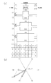
- (A) is a switching pattern (waveform generation pattern) in space vector PWM control in both drive modes, and (b) is a vector diagram in both drive modes.
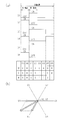
- (A) is a switching pattern (waveform generation pattern) in space vector PWM control in both drive modes, and (b) is a vector diagram in both drive modes.
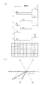
- (A) is a switching pattern (waveform generation pattern) in space vector PWM control in the motor drive mode, and (b) is a vector diagram in the motor drive mode.
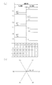
- (A) is a switching pattern (waveform generation pattern) in space vector PWM control in the transforming drive mode, and (b) is a vector diagram in the transforming drive mode.
- the electric motor device 10 shown in FIG. 1 is mounted on a vehicle.
- the electric motor device 10 includes an inverter circuit 20, an electric motor 30, a first power supply 40, a second power supply 50, a control unit 70, and voltage sensors 80 and 81.
- the first power source 40 is a DC power source, for example, a 48-volt on-board battery.
- the first power supply 40 is connected to the positive electrode bus Lp and the negative electrode bus Ln of the inverter circuit 20. That is, the positive electrode of the first power supply 40 is connected to the positive electrode bus Lp, and the negative electrode of the first power supply 40 is connected to the negative electrode bus Ln.
- the electric motor 30 is a three-phase motor and is driven to rotate by three-phase AC power as multiphase AC power.
- the electric motor 30 has three stator coils 31, 32, and 33, and the stator coils 31, 32, and 33 are star-connected.
- the electric motor 30 has a neutral point A.
- the inverter circuit 20 is configured to supply three-phase AC power as multiphase AC power to the electric motor 30.
- the inverter circuit 20 includes switching elements S1 and S2 constituting upper and lower arms for U phase, switching elements S3 and S4 constituting upper and lower arms for V phase, and switching constituting upper and lower arms for W phase. It has elements S5 and S6. IGBTs are used as the switching elements S1 to S6, and diodes (D1 to D6) are connected in antiparallel to the switching elements S1 to S6. Between the positive electrode bus Lp and the negative electrode bus Ln, switching elements S1, S2 are connected in series, switching elements S3, S4 are connected in series, and switching elements S5, S6 are connected in series.
- a portion between the switching elements S1 and S2 is connected to one end of the coil 31 of the three-phase motor 30.
- a portion between the switching elements S3 and S4 is connected to one end of the coil 32 of the three-phase motor 30.
- a portion between the switching elements S5 and S6 is connected to one end of the coil 33 of the three-phase motor 30.
- the inverter circuit 20 includes a plurality of switching element pairs (in detail, including the upper arm side switching elements S1, S3, S5 and the lower arm side switching elements S2, S4, S6 connected in series with each other). 3).
- a capacitor 60 that connects the positive electrode bus Lp and the negative electrode bus Ln is provided closer to the first power supply 40 than the switching elements S1 to S6.
- the second power source 50 is a DC power source, for example, a 12-volt on-board battery. That is, the first power supply 40 is a high-voltage battery that has a higher voltage than the second power supply 50.
- the second power supply 50 is connected to the negative electrode bus Ln of the inverter circuit 20 and the neutral point A of the electric motor 30. Specifically, the positive electrode of the second power supply 50 is connected to the neutral point A of the electric motor 30, and the negative electrode of the second power supply 50 is connected to the negative electrode bus Ln.
- the control unit 70 has a drive circuit 71 and a controller 72.
- the drive circuit 71 is connected to the gate electrodes of the switching elements S1 to S6.
- the controller 72 may include, for example, a control circuit, specifically, one or more dedicated hardware circuits such as an ASIC, one or more processors that operate according to a computer program (software), or a combination thereof.
- the processor includes a CPU and a memory such as a RAM and a ROM, and the memory stores program codes or instructions configured to cause the CPU to execute processing.
- Memory or computer readable media includes any available media that can be accessed by a general purpose or special purpose computer.
- the controller 72 turns the switching elements S1 to S6 on and off via the drive circuit 71.
- the DC power from the first power supply 40 is converted into AC power by the switching operation of the switching elements S1, S2, S3, S4, S5, and S6, and the coils 31, 32, and 33 are star-connected as a multiphase motor.
- the three-phase motor 30 is supplied. That is, space vector PWM control is performed by an inverter (inverter circuit 20, control unit 70, etc.).
- the controller 72 can detect a torque command value (or torque estimated value) and a rotational speed command value (or rotational speed estimated value) by inputting a torque command signal and a rotational speed command signal.
- voltage sensors 80 and 81 are connected to the controller 72.
- the voltage sensor 80 detects the voltage between the terminals of the first power supply 40.
- the voltage sensor 81 detects the voltage between the terminals of the second power supply 50.
- the controller 72 detects the voltage between the terminals of the first power supply 40 and the voltage between the terminals of the second power supply 50 based on signals from the voltage sensors 80 and 81.
- the controller 72 detects the charging state (charging rate) of the first power supply 40 using the voltage between the terminals of the first power supply 40 and also charges the second power supply 50 using the voltage between the terminals of the second power supply 50 ( Charge rate).
- the controller 72 detects the open voltage of the second power supply 50 (the voltage between the terminals of the second power supply 50 in the no-load state: open circuit voltage) from the voltage between the terminals of the second power supply 50. It is determined whether or not the two power sources 50 are fully charged.
- the control unit 70 operates in both drive modes shown in FIGS. 2 (a) and 2 (b) or 3 (a) and 3 (b), and in the motor drive mode shown in FIGS. 4 (a) and 4 (b).
- FIG. 5A and FIG. 5B are configured so as to be able to set the transformer drive mode (step-up / step-down drive mode) shown in FIG.
- the control unit 70 outputs the target torque from the electric motor 30 and the second power source 50.
- the control unit 70 In order to charge the first power supply 40 by stepping up (transforming) the voltage of the first power supply 40, or charging the second power supply 50 by stepping down (transforming) the voltage of the first power supply 40, each switching of the inverter circuit 20 is performed.
- the element pair (S1, S2, S3, S4, S5, S6) is controlled for each control period.
- the control unit 70 also includes a first period in which all the upper arm side switching elements S1, S3, S5 are turned on and all the lower arm side switching elements S2, S4, S6 are turned off, and all the upper arm side switching elements Boosting from the second power supply 50 to the first power supply 40 by adjusting the ratio with the second period in which the switching elements S1, S3, S5 are turned off and all the lower arm switching elements S2, S4, S6 are turned on.
- the ratio (transformation ratio) or the step-down ratio (transformation ratio) from the first power supply 40 to the second power supply 50 can be adjusted.
- the control unit 70 includes the first period and the second period in one control cycle during the driving of the electric motor 30, thereby performing the electric motor driving and the transformer driving (step-up / down driving).
- the controller 72 monitors the charging state of the first power source 40 and the charging state of the second power source 50, and charges the other power source with one power source according to these charging states. That is, the controller 72 boosts the voltage of the second power supply 50 to charge the first power supply 40 when the charging rate of the first power supply 40 is low, and charges the voltage of the first power supply 40 when the charging rate of the second power supply 50 is low. And the second power supply 50 is charged.
- control unit 70 does not include the first period and the second period in one control cycle while the motor 30 is being driven. Only drive.
- the control unit 70 does not drive the motor 30, and the first period and the second period within one control cycle. Is included.
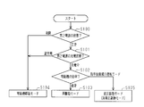
- the control unit 70 is configured to be able to switch between the two drive modes, the motor drive mode, and the transform drive mode for each control cycle. That is, the control unit 70 is configured to select one from a plurality of drive modes for each control cycle. And the control part 70 performs the process shown in FIG. 6, and switches both drive mode, an electric motor drive mode, and a transformation drive mode (step-up / down drive mode) according to the condition of the 2nd power supply 50 and the electric motor 30.
- the timing at which the upper arm side switching elements S1, S3, and S5 fall from on to off, and the lower arm side A delay may be provided so that the timing when the switching elements S2, S4, S6 rise from off to on does not coincide with each other.
- a delay is applied so that the timing at which the upper arm side switching elements S1, S3, S5 rise from off to on and the timing at which the lower arm side switching elements S2, S4, S6 fall from on to off do not coincide. It may be provided.
- a low voltage second power source 50 is connected to the neutral point A of the electric motor 30, and the coils 31, 32, 33 of the electric motor 30 are used as the step-up / step-down inductor, thereby realizing a transformer circuit (step-up / step-down circuit).
- the control method switching method is devised to allow step-up and step-down during motor drive.
- the positive electrode of the low-voltage second power supply 50 is connected to the neutral point A of the electric motor 30.
- the negative electrode of the low-voltage second power supply 50 is the same as the negative electrode of the high-voltage first power supply 40.
- D / (D-1) is the transformation ratio (step-up ratio, step-down ratio).
- D is a duty ratio for the ON time of the zero voltage vector V0 and the ON time of the zero voltage vector V7.
- the inverter performs step-up / step-down (transformation) by adjusting the duty ratio of the upper and lower switching elements S1, S3, S5, S2, S4, and S6. That is, by adjusting the ratio between the first period and the second period, the step-up ratio from the second power source 50 to the first power source 40 or the step-down ratio from the first power source 40 to the second power source 50 is adjusted. Driving is performed. Therefore, the step-up / step-down switch and the inductor can be omitted in the inverter circuit 20, resulting in a small and low-cost system.
- the zero voltage vector V0 and the zero voltage vector V7 have functions of step-up and step-down, for example, voltage vectors V4 and V5. Is applied to the motor 30 as a voltage for driving the motor. At this time, a combined vector B1 which is the sum of the voltage vectors V4 and V5 is a voltage applied to the motor 30.
- the output voltage obtained by the switching shown in FIG. 2 (a) and the output voltage obtained by the switching shown in FIG. 3 (a) are the same as shown in FIG. 2 (b) and FIG. 3 (b). Further, the effect of the step-up / step-down obtained by the switching shown in FIG. 2A is the same as the effect of the step-up / step-down obtained by the switching shown in FIG.
- FIG. 4A shows an example of PWM control when only the motor 30 is driven in the motor drive mode.
- the ON period of the switching element is adjusted to eliminate the period in which the zero voltage vector V0 is generated and the period in which the zero voltage vector V7 is generated. Only the electric motor 30 can be driven.
- the combined vector B1 that is the sum of the voltage vectors V4 and V5 shown in FIG. 2B is the same as the combined vector B2 that is the sum of the voltage vectors V4 and V5 shown in FIG.
- the voltage applied to the electric motor 30 due to this is the same as the voltage applied to the electric motor 30 due to the combined vector B2.
- FIGS. 5 (a) and 5 (b) show the case of the transformation drive mode in which only the step-up / step-down is performed, and only the zero voltage vector V0 and the zero voltage vector V7 may be used. In this transformer drive mode, no torque is generated in the electric motor 30 and the voltage can be increased or decreased.
- the controller 72 determines the state of the second power supply 50 in step S100, that is, determines whether the second power supply 50 is normal (whether a failure has occurred). Specifically, the controller 72 determines whether or not the voltage value between the terminals of the second power supply 50 obtained by the voltage sensor 81 when a voltage is applied is lower than a predetermined threshold value. Then, the controller 72 determines that the second power supply 50 is normal when the voltage value between the terminals of the second power supply 50 is higher than a predetermined threshold value. On the other hand, if the inter-terminal voltage value of the second power supply 50 is lower than a predetermined threshold value, the controller 72 determines that the second power supply 50 has failed.
- the controller 72 determines the charging state of the second power source 50 in step S101, that is, determines whether the second power source 50 is being charged or fully charged. Specifically, the controller 72 determines whether the open-circuit voltage value of the second power supply 50 exceeds a predetermined full charge threshold or is less than a predetermined full charge threshold. And the controller 72 determines with full charge, when the open circuit voltage value of the 2nd power supply 50 has exceeded the predetermined full charge threshold value. On the other hand, the controller 72 determines that charging is being performed when the open circuit voltage value of the second power supply 50 is less than a predetermined full charge threshold.
- the controller 72 determines in step S102 whether the efficiency of the electric motor 30 is normal or an operation mode in a region where the efficiency is low. Specifically, the controller 72 takes in the torque command value and the rotational speed command value, and the efficiency of the electric motor 30 is within a normal range from a three-dimensional map (a map in which the torque command value, the rotational speed command value and the efficiency are defined in advance). Or the low efficiency region.
- the controller 72 sets both drive modes in step S103. Further, the controller 72 sets the motor drive mode in step S104 if the second power supply 50 is broken or the second power supply 50 is fully charged. Further, if the second power source 50 is normal, the second power source 50 is being charged, and the operation mode is in a region where the efficiency of the electric motor 30 is low, the controller 72 determines that torque is not required, and in step S105, the controller 72 performs the transformation drive mode (elevating / lowering). Set the pressure drive mode.
- the controller 72 sets an electric motor drive mode in which the second power source 50 fails or when the second power source 50 is in a fully charged state, it is not necessary to pass a current to the second power source 50.
- the controller 72 is operated in a region where the efficiency of the electric motor 30 is low, it is not necessary to flow a current for torque to the electric motor 30. It can be set.
- the failure determination is performed using the voltage sensor 81, the current flowing through the electric motor 30 may be detected, and if the current value is smaller than the threshold value, it may be determined that the second power source 50 is defective. According to the above embodiment, the following effects can be obtained.
- the electric motor apparatus 10 includes an electric motor 30 that is rotationally driven by three-phase AC power as multiphase AC power, and an inverter circuit 20 that is configured to supply the electric motor 30 with three-phase AC power as multiphase AC power. And comprising.
- the inverter circuit 20 includes a plurality (in detail, three) of switching element pairs including upper arm side switching elements S1, S3, S5 and lower arm side switching elements S2, S4, S6 connected in series with each other. Have.
- the electric motor device 10 includes a first power source 40 connected to the positive electrode bus Lp and the negative electrode bus Ln of the inverter circuit 20, and a first power source connected to the neutral point A of the negative electrode bus Ln of the inverter circuit 20 and the electric motor 30.
- the target torque is output from the two power sources 50 and the electric motor 30, and the voltage of the second power source 50 is increased (transformed) to charge the first power source 40, or the voltage of the first power source 40 is decreased (transformed).
- a control unit 70 is provided for controlling each switching element pair (S1, S2, S3, S4, S5, S6) of the inverter circuit 20 for each control period.
- the control unit 70 includes a first period in which all the upper arm side switching elements S1, S3, S5 are turned on and all the lower arm side switching elements S2, S4, S6 are turned off, and all the upper arm side switching elements.
- the voltage is boosted from the second power supply 50 to the first power supply 40.
- the ratio (transformation ratio) or the step-down ratio (transformation ratio) from the first power supply 40 to the second power supply 50 is adjusted, and one is selected from a plurality of drive modes for each control cycle. Is done.
- the plurality of drive modes include the first period and the second period in one control cycle during the driving of the electric motor 30, so that both the driving mode for performing the electric motor driving and the transformation driving (step-up / down driving), the electric motor 30.
- the motor drive mode performs only motor drive.
- motor drive and transformer drive can be performed.
- the electric motor device 10 can perform a voltage transformation drive (step-up / step-down drive) between two power sources together with the electric motor drive, and can easily perform only the electric motor drive.
- the plurality of drive modes further include a transform drive mode (step-up / step-down drive mode) including the first period and the second period within one control cycle without driving the electric motor 30, and the control unit 70 includes: Depending on the situation of the second power supply 50 and the electric motor 30, one is selected from a plurality of drive modes for each control cycle. Therefore, the electric motor device 10 can easily perform the electric motor drive and the transformer drive between the two power sources, only the motor drive, and only the transformer drive (step-up / down drive) depending on the situation of the second power source 50 and the motor 30. it can.
- a transform drive mode step-up / step-down drive mode
- the state of the second power source 50 includes a state regarding whether or not the second power source 50 has failed, it is possible to drive only the motor when the second power source 50 has failed.
- the first power supply 40 is practical because it is a high-voltage battery having a higher voltage than the second power supply 50.
- the embodiment is not limited to the above, and may be embodied as follows, for example.
- the control unit 70 selects one from a plurality of drive modes according to the situation of the second power supply 50, but even if one is selected from a plurality of drive modes according to the situation of the first power supply 40 Good.
- the number of phases of the electric motor 30 can be other than three.
- the voltage range of the first power supply 40 and the second power supply 50 is 12 volts, 24 volts, 48 volts, etc., so long as the negative electrode of the first power supply 40 and the negative electrode of the second power supply 50 can be shared. I do not care.
- the second power source 50 has a lower voltage than the first power source 40, but the second power source 50 may have a higher voltage than the first power source 40.
- the first power source 40 and the second power source 50 may be secondary batteries or capacitors.
- the switching elements S1 to S6 are not limited to IGBTs, and may be power MOSFETs, for example.
Landscapes
- Engineering & Computer Science (AREA)
- Power Engineering (AREA)
- Inverter Devices (AREA)
- Control Of Ac Motors In General (AREA)
- Electric Propulsion And Braking For Vehicles (AREA)
Abstract
電動機装置は制御部を備える。制御部は、全ての上アーム側スイッチング素子がオンになるとともに全ての下アーム側スイッチング素子がオフになる第1期間と、全ての上アーム側スイッチング素子がオフになるとともに全ての下アーム側スイッチング素子がオンになる第2期間との比率を調整することによって、変圧比を調整するように構成されるとともに、制御周期毎に複数の駆動モードから1つを選定するように構成される。複数の駆動モードは、電動機の駆動中の1つの制御周期内に第1期間及び第2期間を含む両駆動モードと、電動機の駆動中の1つの制御周期内に第1期間及び第2期間を含まない電動機駆動モードとを有する。
Description
本発明は、電動機装置に関するものである。
電動機装置において、直流電源による直流をインバータで交流に変換して電動機に供給する際に、インバータの前段に配置された、スイッチとインダクタとで構成される変圧回路によって、直流を変圧する技術がある。このようなシステムでは非常に高価で体格も大きなスイッチやインダクタが必要になる。これに対し、特許文献1は、ステータコイルの中性点にバッテリを接続し昇圧制御を行う電動機装置を開示している。また、当該電動機装置は、不良時にはバッテリと中性点との間に設けたスイッチを開く。
電動機駆動中にも変圧動作を行うことが必要な場合もあれば、電動機駆動のみを行うことが必要な場合もある。また、特許文献1に開示の技術では不良時にスイッチを開ける必要があった。
本発明の目的は、電動機駆動と2つの電源間の変圧駆動を一緒に行うことができ、電動機駆動のみも容易に行うことができる電動機装置を提供することにある。
上記課題を解決する電動機装置は、多相交流電力により回転駆動するように構成された電動機と、正極母線と負極母線とを有し、前記電動機に多相交流電力を供給するように構成されたインバータ回路であって、互いに直列に接続された上アーム側スイッチング素子と下アーム側スイッチング素子とから構成されるスイッチング素子対を複数有するインバータ回路と、前記正極母線と前記負極母線とに接続された第1電源と、前記負極母線と前記電動機の中性点とに接続された第2電源と、前記電動機から目標トルクを出力させるとともに、前記第2電源の電圧を変圧して前記第1電源を充電すること、または前記第1電源の電圧を変圧して前記第2電源を充電することを行うべく、前記インバータ回路の各スイッチング素子対を制御周期毎に制御するように構成された制御部と、を備える。前記制御部は、全ての上アーム側スイッチング素子がオンになるとともに全ての下アーム側スイッチング素子がオフになる第1期間と、全ての上アーム側スイッチング素子がオフになるとともに全ての下アーム側スイッチング素子がオンになる第2期間との比率を調整することによって、前記第2電源から前記第1電源への変圧比または前記第1電源から前記第2電源への変圧比を調整するように構成されるとともに、前記制御周期毎に複数の駆動モードから1つを選定するように構成される。前記複数の駆動モードは、前記電動機の駆動中の1つの制御周期内に前記第1期間及び前記第2期間を含むことで、電動機駆動と変圧駆動とを行う両駆動モードと、前記電動機の駆動中の1つの制御周期内に前記第1期間及び前記第2期間を含まないことで、電動機駆動のみを行う電動機駆動モードとを有する。
以下、本発明を具体化した一実施形態を図面に従って説明する。
図1に示す電動機装置10は車両に搭載される。電動機装置10は、インバータ回路20と電動機30と第1電源40と第2電源50と制御部70と電圧センサ80,81を備えている。
図1に示す電動機装置10は車両に搭載される。電動機装置10は、インバータ回路20と電動機30と第1電源40と第2電源50と制御部70と電圧センサ80,81を備えている。
第1電源40は、直流電源であり、例えば48ボルトの車載バッテリである。第1電源40は、インバータ回路20の正極母線Lpと負極母線Lnとに接続されている。つまり、第1電源40の正極が正極母線Lpに接続されるとともに第1電源40の負極が負極母線Lnと接続されている。
電動機30は3相モータであって、多相交流電力としての3相交流電力により回転駆動する。電動機30は3つのステータコイル31,32,33を有し、ステータコイル31,32,33はスター結線されている。電動機30は中性点Aを有する。
インバータ回路20は、電動機30に多相交流電力としての3相交流電力を供給するように構成されている。インバータ回路20は、U相用の上下のアームを構成するスイッチング素子S1,S2と、V相用の上下のアームを構成するスイッチング素子S3,S4と、W相用の上下のアームを構成するスイッチング素子S5,S6を有する。スイッチング素子S1~S6としてIGBTが使用され、各スイッチング素子S1~S6にはダイオード(D1~D6)が逆並列接続されている。正極母線Lpと負極母線Lnとの間において、スイッチング素子S1,S2が直列に接続され、スイッチング素子S3,S4が直列に接続され、スイッチング素子S5,S6が直列に接続されている。スイッチング素子S1,S2間の箇所が3相電動機30のコイル31の一端と接続されている。スイッチング素子S3,S4間の箇所が3相電動機30のコイル32の一端と接続されている。スイッチング素子S5,S6間の箇所が3相電動機30のコイル33の一端と接続されている。
このように、インバータ回路20は、互いに直列に接続された上アーム側スイッチング素子S1,S3,S5と下アーム側スイッチング素子S2,S4,S6とから構成されるスイッチング素子対を複数(詳細には、3つ)有する。また、正極母線Lpと負極母線Lnとを接続するコンデンサ60が、スイッチング素子S1~S6よりも第1電源40の近くに設けられている。
第2電源50は、直流電源であり、例えば12ボルトの車載バッテリである。即ち、第1電源40は第2電源50と比較して高圧である高圧バッテリである。第2電源50は、インバータ回路20の負極母線Lnと電動機30の中性点Aとに接続されている。詳しくは、第2電源50の正極が電動機30の中性点Aに接続されるとともに第2電源50の負極が負極母線Lnと接続されている。
制御部70はドライブ回路71とコントローラ72を有する。ドライブ回路71は各スイッチング素子S1~S6のゲート電極と接続されている。コントローラ72は、例えば制御回路、具体的には、ASIC等の1つ以上の専用のハードウェア回路、コンピュータプログラム(ソフトウェア)に従って動作する1つ以上のプロセッサ、或いはそれらの組み合わせを含み得る。プロセッサは、CPU並びに、RAM及びROM等のメモリを含み、メモリは、処理をCPUに実行させるように構成されたプログラムコードまたは指令を格納している。メモリすなわちコンピュータ可読媒体は、汎用または専用のコンピュータでアクセスできるあらゆる利用可能な媒体を含む。コントローラ72は、ドライブ回路71を介して各スイッチング素子S1~S6をオンオフする。つまり、スイッチング素子S1,S2,S3,S4,S5,S6のスイッチング動作により第1電源40からの直流電力を交流電力に変換してコイル31,32,33がスター結線された多相電動機としての3相電動機30に供給する。すなわち、インバータ(インバータ回路20、制御部70等)により空間ベクトルPWM制御が行われる。コントローラ72はトルク指令信号及び回転数指令信号を入力してトルク指令値(もしくはトルク推定値)及び回転数指令値(もしくは回転数推定値)を検知することができるようになっている。また、コントローラ72には電圧センサ80,81が接続されている。電圧センサ80は第1電源40の端子間電圧を検出する。電圧センサ81は第2電源50の端子間電圧を検出する。コントローラ72は電圧センサ80,81からの信号により第1電源40の端子間電圧及び第2電源50の端子間電圧を検知する。また、コントローラ72は第1電源40の端子間電圧を用いて第1電源40の充電状態(充電率)を検知するとともに第2電源50の端子間電圧を用いて第2電源50の充電状態(充電率)を検知する。さらに、コントローラ72は第2電源50の端子間電圧から第2電源50の開放電圧(無負荷状態での第2電源50の端子間電圧:開回路電圧)を検知しており、これにより、第2電源50が満充電であるか否かを判断することになる。
制御部70は、図2(a)及び図2(b)あるいは図3(a)及び図3(b)に示す両駆動モード、図4(a)及び図4(b)に示す電動機駆動モード、図5(a)及び図5(b)に示す変圧駆動モード(昇降圧駆動モード)を設定可能に構成されている。
図2(a)及び図2(b)あるいは図3(a)及び図3(b)に示す両駆動モードにおいては、制御部70は、電動機30から目標トルクを出力させるとともに、第2電源50の電圧を昇圧(変圧)して第1電源40を充電すること、または第1電源40の電圧を降圧(変圧)して第2電源50を充電することを行うべく、インバータ回路20の各スイッチング素子対(S1,S2、S3,S4、S5,S6)を制御周期毎に制御する。また、制御部70は、全ての上アーム側スイッチング素子S1,S3,S5がオンになるとともに全ての下アーム側スイッチング素子S2,S4,S6がオフになる第1期間と、全ての上アーム側スイッチング素子S1,S3,S5がオフになるとともに全ての下アーム側スイッチング素子S2,S4,S6がオンになる第2期間との比率を調整して第2電源50から第1電源40への昇圧比(変圧比)または第1電源40から第2電源50への降圧比(変圧比)を調整可能に構成されている。そして、両駆動モードでは、制御部70は、電動機30の駆動中の1つの制御周期内に第1期間及び第2期間を含むことで、電動機駆動と変圧駆動(昇降圧駆動)とを行う。詳しくは、コントローラ72は、第1電源40の充電状態と第2電源50の充電状態を監視しており、これらの充電状態に応じて一方の電源で他方の電源を充電する。つまり、コントローラ72は、第1電源40の充電率が低いと第2電源50の電圧を昇圧して第1電源40を充電させ、第2電源50の充電率が低いと第1電源40の電圧を降圧して第2電源50を充電させる。
図4(a)及び図4(b)に示す電動機駆動モードにおいては、制御部70は、電動機30の駆動中の1つの制御周期内に第1期間及び第2期間を含まないことで、電動機駆動のみを行う。
図5(a)及び図5(b)に示す変圧駆動モード(昇降圧駆動モード)においては、制御部70は、電動機30を駆動せずに1つの制御周期内に第1期間及び第2期間を含んでいる。
制御部70は、両駆動モードと電動機駆動モードと変圧駆動モードとを制御周期毎に切り替え可能に構成されている。すなわち、制御部70は、制御周期毎に複数の駆動モードから1つを選定するように構成されている。そして、制御部70は図6に示す処理を実行して、第2電源50及び電動機30の状況に応じて、両駆動モード、電動機駆動モード及び変圧駆動モード(昇降圧駆動モード)を切り替える。
なお、図2(a)、図3(a)、図4(a)、図5(a)において、上アーム側スイッチング素子S1,S3,S5がオンからオフに立ち下がるタイミングと、下アーム側スイッチング素子S2,S4,S6がオフからオンに立ち上がるタイミングとが、同時とならないようにディレイーを設けてもよい。同様に、上アーム側スイッチング素子S1,S3,S5がオフからオンに立ち上がるタイミングと、下アーム側スイッチング素子S2,S4,S6がオンからオフに立ち下がるタイミングとが、同時とならないようにディレイーを設けてもよい。
以下、両駆動モード、電動機駆動モード、変圧駆動モードについて、詳しく説明する。
電動機30の中性点Aに低圧の第2電源50を接続し、電動機30のコイル31,32,33を昇降圧用インダクタとして利用することにより変圧回路(昇降圧回路)を実現することとし、そのために制御方法(スイッチング方法)を工夫して電動機駆動の実行中に昇圧及び降圧も行うことを可能にしている。
電動機30の中性点Aに低圧の第2電源50を接続し、電動機30のコイル31,32,33を昇降圧用インダクタとして利用することにより変圧回路(昇降圧回路)を実現することとし、そのために制御方法(スイッチング方法)を工夫して電動機駆動の実行中に昇圧及び降圧も行うことを可能にしている。
図1に示すように、低圧の第2電源50の正極が電動機30の中性点Aに接続されている。低圧の第2電源50の負極は高圧の第1電源40の負極と共通である。ここで、インバータを通常動作させる際、上アーム用のスイッチング素子S1,S3,S5を同時にオンする第1期間と、下アーム用のスイッチング素子S2,S4,S6を同時にオンする第2期間とがあり、第1期間及び第2期間においては電動機30にはトルクが掛からない。また、D/(D-1)が変圧比(昇圧比、降圧比)となる。ここで、Dは、零電圧ベクトルV0のオン時間と零電圧ベクトルV7のオン時間についてのデューティ比である。即ち、図2(a)において、零電圧ベクトルV7のオン期間をT1、零電圧ベクトルV0の前期オン期間をT2、零電圧ベクトルV0の後期オン期間をT3とすると、変圧比は、{T1/(T1+T2+T3)}/{(T1/(T1+T2+T3))-1}となる。
そして、インバータは、上下のスイッチング素子S1,S3,S5、S2,S4,S6のデューティ比を調整することで昇降圧(変圧)を行う。つまり、第1期間と第2期間との比率を調整することにより第2電源50から第1電源40への昇圧比または第1電源40から第2電源50への降圧比を調整して昇降圧駆動が行われる。よって、インバータ回路20において昇降圧用のスイッチ及びインダクタを省略でき、小型かつ低コストなシステムとなる。
通常の制御(両駆動モード)の場合、図2(a)及び図2(b)に示すように零電圧ベクトルV0と零電圧ベクトルV7が昇圧及び降圧の機能を持ち、例えば電圧ベクトルV4,V5が電動機駆動の電圧として電動機30に掛かる。この時、電圧ベクトルV4,V5の総和である合成ベクトルB1が電動機30に掛かる電圧である。
図2(a)に示すスイッチングにより得られる出力電圧と、図3(a)に示すスイッチングにより得られる出力電圧とは、図2(b)及び図3(b)に示すように同じである。また、図2(a)に示すスイッチングにより得られる昇降圧の効果と、図3(a)に示すスイッチングにより得られる昇降圧の効果とは、同じである。
図4(a)においては電動機駆動モードでの電動機30のみを駆動する時のPWM制御例を示す。図4(a)に示すように、スイッチング素子のオン期間を調整して、零電圧ベクトルV0が生じる期間と零電圧ベクトルV7が生じる期間をなくすことで昇圧・降圧を行わず(中性点Aに電流が流れなくなり)、電動機30のみの駆動が可能である。図2(b)に示す電圧ベクトルV4,V5の総和である合成ベクトルB1と、図4(b)に示す電圧ベクトルV4,V5の総和である合成ベクトルB2とが同じであり、合成ベクトルB1に起因して電動機30に掛かる電圧と、合成ベクトルB2に起因して電動機30に掛かる電圧とは同じとなる。
このようにして、電動機30のみの駆動(中性点Aに電流が流れない)を可能とする。更に昇降圧(変圧)のみの変圧駆動モードも可能とし、3種のモードを使い分けることが可能になる。
図5(a)及び図5(b)は、昇降圧のみを行わせる変圧駆動モードの場合であり、単純に零電圧ベクトルV0と零電圧ベクトルV7のみ使えばよい。この変圧駆動モードでは、電動機30にはトルクが発生せず昇降圧が可能である。
このように、1スイッチング周期における空間ベクトルが互いに異なる両駆動モード、電動機駆動モード、変圧駆動モードを運転状況等に応じ使い分ける事が可能である。
次に、作用について説明する。
次に、作用について説明する。
図6に示すように、コントローラ72は、ステップS100において第2電源50の状態を判定、すなわち第2電源50が正常か否か(故障が発生したか否か)を判定する。具体的には、コントローラ72は、電圧印加時に電圧センサ81により得られる第2電源50の端子間電圧値が所定の閾値より低いか否か判定する。そして、コントローラ72は、当該第2電源50の端子間電圧値が所定の閾値よりも高いと第2電源50が正常であると判定する。一方、コントローラ72は、当該第2電源50の端子間電圧値が所定の閾値よりも低いと第2電源50が故障した状態であると判定する。
図6に示すように、コントローラ72は、ステップS101において第2電源50の充電状態を判定、すなわち第2電源50が充電中か満充電かを判定する。具体的には、コントローラ72は、第2電源50の開放電圧値が所定の満充電閾値を超えているか、あるいは所定の満充電閾値未満かを判定する。そして、コントローラ72は、第2電源50の開放電圧値が所定の満充電閾値を超えていると満充電と判定する。一方、コントローラ72は、第2電源50の開放電圧値が所定の満充電閾値未満であると充電中と判定する。
図6に示すように、コントローラ72は、ステップS102において電動機30の効率が通常か、あるいは効率が低い領域の運転モードかを判定する。具体的には、コントローラ72は、トルク指令値と回転数指令値を取り込んで三次元マップ(トルク指令値と回転数指令値と効率とを予め規定したマップ)から、電動機30の効率が通常領域か低効率領域かを判定する。
図6に示すように、コントローラ72は、第2電源50が正常で、第2電源50が充電中で、電動機30の効率が通常ならば、ステップS103で両駆動モードを設定する。また、コントローラ72は、第2電源50が故障、あるいは、第2電源50が満充電ならば、ステップS104で電動機駆動モードを設定する。さらに、コントローラ72は、第2電源50が正常で、第2電源50が充電中で、電動機30の効率が低い領域の運転モードならば、トルクが不要であるとしてステップS105で変圧駆動モード(昇降圧駆動モード)を設定する。
このようにして、コントローラ72は、第2電源50が故障する、または第2電源50の満充電状態では第2電源50に電流を流す必要がない電動機駆動モードを設定する。また、コントローラ72は、電動機30の効率が低い領域で運転される場合は電動機30にトルク用の電流を流す必要がないので、昇降圧(変圧)のみの変圧駆動モード(昇降圧駆動モード)を設定可能である。
故障判定は電圧センサ81を用いて行ったが、電動機30に流れる電流を検出して電流値が閾値よりも小さいと第2電源50が故障であると判定してもよい。
上記実施形態によれば、以下のような効果を得ることができる。
上記実施形態によれば、以下のような効果を得ることができる。
(1)電動機装置10は、多相交流電力としての3相交流電力により回転駆動する電動機30と、電動機30に多相交流電力としての3相交流電力を供給するように構成されたインバータ回路20と、を備える。インバータ回路20は、互いに直列に接続された上アーム側スイッチング素子S1,S3,S5と下アーム側スイッチング素子S2,S4,S6とから構成されるスイッチング素子対を複数(詳細には、3つ)有する。また、電動機装置10は、インバータ回路20の正極母線Lpと負極母線Lnとに接続された第1電源40と、インバータ回路20の負極母線Lnと電動機30の中性点Aとに接続された第2電源50と、電動機30から目標トルクを出力させるとともに、第2電源50の電圧を昇圧(変圧)して第1電源40を充電すること、または第1電源40の電圧を降圧(変圧)して第2電源50を充電することを行うべく、インバータ回路20の各スイッチング素子対(S1,S2、S3,S4、S5,S6)を制御周期毎に制御する制御部70と、を備える。制御部70は、全ての上アーム側スイッチング素子S1,S3,S5がオンになるとともに全ての下アーム側スイッチング素子S2,S4,S6がオフになる第1期間と、全ての上アーム側スイッチング素子S1,S3,S5がオフになるとともに全ての下アーム側スイッチング素子S2,S4,S6がオンになる第2期間との比率を調整することによって、第2電源50から第1電源40への昇圧比(変圧比)または第1電源40から第2電源50への降圧比(変圧比)を調整するように構成されるとともに、制御周期毎に複数の駆動モードから1つを選定するように構成される。複数の駆動モードは、電動機30の駆動中の1つの制御周期内に第1期間及び第2期間を含むことで、電動機駆動と変圧駆動(昇降圧駆動)とを行う両駆動モードと、電動機30の駆動中の1つの制御周期内に第1期間及び第2期間を含まないことで、電動機駆動のみを行う電動機駆動モードとを有する。このように、両駆動モードにおいては、電動機駆動と変圧駆動とを行うことができる。また、電動機駆動モードにおいては、スイッチを開ける動作を不要にして電動機駆動のみを行うことができる。よって、電動機装置10は、電動機駆動とともに2つの電源間の変圧駆動(昇降圧駆動)を行うことができ、電動機駆動のみも容易に行うことができる。
(2)複数の駆動モードは、電動機30を駆動せずに1つの制御周期内に第1期間及び第2期間を含む変圧駆動モード(昇降圧駆動モード)を更に有し、制御部70は、第2電源50及び電動機30の状況に応じて、制御周期毎に複数の駆動モードから1つを選定するように構成されている。よって、電動機装置10は、第2電源50及び電動機30の状況に応じて、電動機駆動と2つの電源間の変圧駆動、電動機駆動のみ、変圧駆動(昇降圧駆動)のみ、を容易に行うことができる。
(3)第2電源50の状況は、第2電源50の故障の有無についての状況を含むので、第2電源50が故障の場合においては電動機駆動のみを行うことが可能となる。
(4)第1電源40は第2電源50と比較して高圧である高圧バッテリであるので実用的である。
(4)第1電源40は第2電源50と比較して高圧である高圧バッテリであるので実用的である。
実施形態は前記に限定されるものではなく、例えば、次のように具体化してもよい。
・制御部70は、第2電源50の状況に応じて複数の駆動モードから1つを選定していたが、第1電源40の状況に応じて複数の駆動モードから1つを選定してもよい。
・制御部70は、第2電源50の状況に応じて複数の駆動モードから1つを選定していたが、第1電源40の状況に応じて複数の駆動モードから1つを選定してもよい。
・電動機30の相数は3相以外の相数でも可能である。
・第1電源40及び第2電源50の電圧の範囲も12ボルト、24ボルト、48ボルトなど、第1電源40の負極と第2電源50の負極とを共通にできるのであればいかなる電源電圧でも構わない。
・第1電源40及び第2電源50の電圧の範囲も12ボルト、24ボルト、48ボルトなど、第1電源40の負極と第2電源50の負極とを共通にできるのであればいかなる電源電圧でも構わない。
・第2電源50は第1電源40に比べ低圧であったが、第2電源50は第1電源40に比べ高圧であってもよい。
・第1電源40と第2電源50は二次電池でもキャパシタ等でもよい。
・第1電源40と第2電源50は二次電池でもキャパシタ等でもよい。
・スイッチング素子S1~S6はIGBTに限ることはなく、例えばパワーMOSFETであってもよい。
Claims (4)
- 多相交流電力により回転駆動するように構成された電動機と、
正極母線と負極母線とを有し、前記電動機に多相交流電力を供給するように構成されたインバータ回路であって、互いに直列に接続された上アーム側スイッチング素子と下アーム側スイッチング素子とから構成されるスイッチング素子対を複数有するインバータ回路と、
前記正極母線と前記負極母線とに接続された第1電源と、
前記負極母線と前記電動機の中性点とに接続された第2電源と、
前記電動機から目標トルクを出力させるとともに、前記第2電源の電圧を変圧して前記第1電源を充電すること、または前記第1電源の電圧を変圧して前記第2電源を充電することを行うべく、前記インバータ回路の各スイッチング素子対を制御周期毎に制御するように構成された制御部と、
を備え、
前記制御部は、
全ての上アーム側スイッチング素子がオンになるとともに全ての下アーム側スイッチング素子がオフになる第1期間と、全ての上アーム側スイッチング素子がオフになるとともに全ての下アーム側スイッチング素子がオンになる第2期間との比率を調整することによって、前記第2電源から前記第1電源への変圧比または前記第1電源から前記第2電源への変圧比を調整するように構成されるとともに、
前記制御周期毎に複数の駆動モードから1つを選定するように構成され、
前記複数の駆動モードは、前記電動機の駆動中の1つの制御周期内に前記第1期間及び前記第2期間を含むことで、電動機駆動と変圧駆動とを行う両駆動モードと、前記電動機の駆動中の1つの制御周期内に前記第1期間及び前記第2期間を含まないことで、電動機駆動のみを行う電動機駆動モードとを有する電動機装置。 - 前記複数の駆動モードは、前記電動機を駆動せずに1つの制御周期内に前記第1期間及び前記第2期間を含む変圧駆動モードを更に有し、
前記制御部は、前記第1電源または前記第2電源の状況及び電動機の状況に応じて、前記制御周期毎に前記複数の駆動モードから1つを選定するように構成されている請求項1に記載の電動機装置。 - 前記第1電源または前記第2電源の状況は、前記第1電源または前記第2電源の故障の有無についての状況を含む請求項2に記載の電動機装置。
- 前記第1電源は前記第2電源と比較して高圧である高圧バッテリである請求項1~3のいずれか1項に記載の電動機装置。
Priority Applications (3)
| Application Number | Priority Date | Filing Date | Title |
|---|---|---|---|
| CN201780021029.XA CN109121460B (zh) | 2016-04-07 | 2017-03-31 | 电动机装置 |
| US16/090,982 US10574168B2 (en) | 2016-04-07 | 2017-03-31 | Electrical motor device |
| EP17779060.7A EP3442112A4 (en) | 2016-04-07 | 2017-03-31 | ELECTRIC MOTOR DEVICE |
Applications Claiming Priority (2)
| Application Number | Priority Date | Filing Date | Title |
|---|---|---|---|
| JP2016-077294 | 2016-04-07 | ||
| JP2016077294A JP6547672B2 (ja) | 2016-04-07 | 2016-04-07 | 電動機装置 |
Publications (1)
| Publication Number | Publication Date |
|---|---|
| WO2017175681A1 true WO2017175681A1 (ja) | 2017-10-12 |
Family
ID=60000466
Family Applications (1)
| Application Number | Title | Priority Date | Filing Date |
|---|---|---|---|
| PCT/JP2017/013682 WO2017175681A1 (ja) | 2016-04-07 | 2017-03-31 | 電動機装置 |
Country Status (5)
| Country | Link |
|---|---|
| US (1) | US10574168B2 (ja) |
| EP (1) | EP3442112A4 (ja) |
| JP (1) | JP6547672B2 (ja) |
| CN (1) | CN109121460B (ja) |
| WO (1) | WO2017175681A1 (ja) |
Families Citing this family (3)
| Publication number | Priority date | Publication date | Assignee | Title |
|---|---|---|---|---|
| CN109905051B (zh) * | 2019-04-01 | 2020-12-01 | 北京交通大学 | 三相逆变器的相电压均衡装置及均衡方法 |
| CN110798117B (zh) * | 2019-10-12 | 2021-08-31 | 华中科技大学 | 一种磁场调制开关磁阻电机双电端口驱动系统及控制方法 |
| CN112937337A (zh) * | 2021-01-21 | 2021-06-11 | 华为技术有限公司 | 一种充电系统及电动汽车 |
Citations (5)
| Publication number | Priority date | Publication date | Assignee | Title |
|---|---|---|---|---|
| JP2003102181A (ja) * | 2001-09-25 | 2003-04-04 | Toyota Motor Corp | 電力供給システムおよび電力供給方法 |
| JP2003116280A (ja) * | 2001-10-04 | 2003-04-18 | Toyota Motor Corp | 駆動装置および動力出力装置 |
| JP2009118633A (ja) * | 2007-11-06 | 2009-05-28 | Denso Corp | 多相回転電機の制御装置及び多相回転電機装置 |
| JP2013093966A (ja) * | 2011-10-25 | 2013-05-16 | Denso Corp | ブラシレス発電電動機の制御装置 |
| US20150321578A1 (en) * | 2013-01-17 | 2015-11-12 | Bayerische Motoren Werke Aktiengesellschaft | Vehicle Having an Electric Machine and Two Onboard Power Subsystems |
Family Cites Families (12)
| Publication number | Priority date | Publication date | Assignee | Title |
|---|---|---|---|---|
| JPH10113105A (ja) * | 1996-10-09 | 1998-05-06 | Ryobi Ltd | 魚釣用電動リールのスプール駆動モータ制御装置およびスプール駆動モータ制御方法 |
| US6518736B2 (en) * | 2000-06-26 | 2003-02-11 | Toyota Jidosha Kabushiki Kaisha | Mechanical power outputting apparatus and inverter apparatus |
| JP4346813B2 (ja) * | 2000-11-15 | 2009-10-21 | トヨタ自動車株式会社 | 動力出力装置およびその制御方法 |
| JP2005204431A (ja) * | 2004-01-16 | 2005-07-28 | Matsushita Electric Ind Co Ltd | モータ駆動装置 |
| JP2005354825A (ja) * | 2004-06-11 | 2005-12-22 | Nissan Motor Co Ltd | ハイブリッド車両のsoc演算装置 |
| JP4441920B2 (ja) | 2007-11-22 | 2010-03-31 | 株式会社デンソー | 電源装置 |
| JP5385058B2 (ja) | 2009-09-04 | 2014-01-08 | 株式会社日本自動車部品総合研究所 | 車両のモータ制御装置 |
| JP5505042B2 (ja) * | 2010-03-31 | 2014-05-28 | 株式会社豊田自動織機 | 中性点昇圧方式の直流−三相変換装置 |
| JP5567381B2 (ja) * | 2010-04-27 | 2014-08-06 | 日立オートモティブシステムズ株式会社 | 電力変換装置 |
| US9479084B2 (en) | 2013-02-20 | 2016-10-25 | Infineon Technologies Ag | Pseudo zero vectors for space vector modulation and enhanced space vector modulation |
| KR101804713B1 (ko) * | 2013-10-18 | 2018-01-10 | 미쓰비시덴키 가부시키가이샤 | 직류 전원 장치, 전동기 구동 장치, 공기 조화기 및 냉장고 |
| US10315530B2 (en) * | 2015-04-16 | 2019-06-11 | Hyundai Motor Company | System and method for reducing speed ripple of drive motor of electric vehicle |
-
2016
- 2016-04-07 JP JP2016077294A patent/JP6547672B2/ja not_active Expired - Fee Related
-
2017
- 2017-03-31 EP EP17779060.7A patent/EP3442112A4/en not_active Ceased
- 2017-03-31 WO PCT/JP2017/013682 patent/WO2017175681A1/ja active Application Filing
- 2017-03-31 CN CN201780021029.XA patent/CN109121460B/zh not_active Expired - Fee Related
- 2017-03-31 US US16/090,982 patent/US10574168B2/en not_active Expired - Fee Related
Patent Citations (5)
| Publication number | Priority date | Publication date | Assignee | Title |
|---|---|---|---|---|
| JP2003102181A (ja) * | 2001-09-25 | 2003-04-04 | Toyota Motor Corp | 電力供給システムおよび電力供給方法 |
| JP2003116280A (ja) * | 2001-10-04 | 2003-04-18 | Toyota Motor Corp | 駆動装置および動力出力装置 |
| JP2009118633A (ja) * | 2007-11-06 | 2009-05-28 | Denso Corp | 多相回転電機の制御装置及び多相回転電機装置 |
| JP2013093966A (ja) * | 2011-10-25 | 2013-05-16 | Denso Corp | ブラシレス発電電動機の制御装置 |
| US20150321578A1 (en) * | 2013-01-17 | 2015-11-12 | Bayerische Motoren Werke Aktiengesellschaft | Vehicle Having an Electric Machine and Two Onboard Power Subsystems |
Non-Patent Citations (1)
| Title |
|---|
| See also references of EP3442112A4 * |
Also Published As
| Publication number | Publication date |
|---|---|
| EP3442112A1 (en) | 2019-02-13 |
| CN109121460B (zh) | 2020-07-07 |
| US20190115863A1 (en) | 2019-04-18 |
| EP3442112A4 (en) | 2019-04-10 |
| US10574168B2 (en) | 2020-02-25 |
| JP6547672B2 (ja) | 2019-07-24 |
| CN109121460A (zh) | 2019-01-01 |
| JP2017189053A (ja) | 2017-10-12 |
Similar Documents
| Publication | Publication Date | Title |
|---|---|---|
| JP7370223B2 (ja) | 電力変換装置 | |
| TWI625022B (zh) | 電力轉換系統 | |
| US20110149624A1 (en) | Power conversion apparatus | |
| TWI625021B (zh) | 電力轉換系統 | |
| WO2015004948A1 (ja) | 放電制御装置 | |
| JP6458871B2 (ja) | 電力調整システム及びその制御方法 | |
| KR20150129619A (ko) | 전동 차량 | |
| JP2015073423A (ja) | 電動車用電力変換システム | |
| KR101356277B1 (ko) | 교류 모터 구동 장치 | |
| KR20220062832A (ko) | 모터 구동 장치를 이용한 멀티 입력 충전 시스템 및 방법 | |
| WO2017175681A1 (ja) | 電動機装置 | |
| WO2017213073A1 (ja) | 動力出力装置 | |
| JP2023105457A (ja) | 電力変換装置 | |
| JP6513249B1 (ja) | Dc/dcコンバータ | |
| US10972015B2 (en) | Method of initiating a regenerative converter and a regenerative converter | |
| JP2002027779A (ja) | 動力出力装置 | |
| JP6079455B2 (ja) | 充電装置及び制御方法 | |
| KR20150040232A (ko) | 전동차용 전력변환 시스템 | |
| US20150349674A1 (en) | Multiaxial driving apparatus | |
| JP4549124B2 (ja) | モータ制御装置 | |
| WO2023089746A1 (ja) | モータ制御装置 | |
| JP7029269B2 (ja) | 電力変換装置 | |
| JP2016208736A (ja) | 電力変換装置 | |
| JP6129106B2 (ja) | 外部給電システム | |
| JP5712773B2 (ja) | 電動機駆動装置 |
Legal Events
| Date | Code | Title | Description |
|---|---|---|---|
| NENP | Non-entry into the national phase |
Ref country code: DE |
|
| WWE | Wipo information: entry into national phase |
Ref document number: 2017779060 Country of ref document: EP |
|
| ENP | Entry into the national phase |
Ref document number: 2017779060 Country of ref document: EP Effective date: 20181107 |
|
| 121 | Ep: the epo has been informed by wipo that ep was designated in this application |
Ref document number: 17779060 Country of ref document: EP Kind code of ref document: A1 |