WO2017169750A1 - エンジンのカムジャーナル潤滑油供給機構 - Google Patents
エンジンのカムジャーナル潤滑油供給機構 Download PDFInfo
- Publication number
- WO2017169750A1 WO2017169750A1 PCT/JP2017/010263 JP2017010263W WO2017169750A1 WO 2017169750 A1 WO2017169750 A1 WO 2017169750A1 JP 2017010263 W JP2017010263 W JP 2017010263W WO 2017169750 A1 WO2017169750 A1 WO 2017169750A1
- Authority
- WO
- WIPO (PCT)
- Prior art keywords
- cam
- oil
- journal
- exhaust
- passage
- Prior art date
- Legal status (The legal status is an assumption and is not a legal conclusion. Google has not performed a legal analysis and makes no representation as to the accuracy of the status listed.)
- Ceased
Links
Images


Classifications
-
- F—MECHANICAL ENGINEERING; LIGHTING; HEATING; WEAPONS; BLASTING
- F01—MACHINES OR ENGINES IN GENERAL; ENGINE PLANTS IN GENERAL; STEAM ENGINES
- F01M—LUBRICATING OF MACHINES OR ENGINES IN GENERAL; LUBRICATING INTERNAL COMBUSTION ENGINES; CRANKCASE VENTILATING
- F01M9/00—Lubrication means having pertinent characteristics not provided for in, or of interest apart from, groups F01M1/00 - F01M7/00
- F01M9/10—Lubrication of valve gear or auxiliaries
- F01M9/102—Lubrication of valve gear or auxiliaries of camshaft bearings
-
- F—MECHANICAL ENGINEERING; LIGHTING; HEATING; WEAPONS; BLASTING
- F01—MACHINES OR ENGINES IN GENERAL; ENGINE PLANTS IN GENERAL; STEAM ENGINES
- F01L—CYCLICALLY OPERATING VALVES FOR MACHINES OR ENGINES
- F01L1/00—Valve-gear or valve arrangements, e.g. lift-valve gear
- F01L1/02—Valve drive
- F01L1/04—Valve drive by means of cams, camshafts, cam discs, eccentrics or the like
- F01L1/047—Camshafts
-
- F—MECHANICAL ENGINEERING; LIGHTING; HEATING; WEAPONS; BLASTING
- F01—MACHINES OR ENGINES IN GENERAL; ENGINE PLANTS IN GENERAL; STEAM ENGINES
- F01L—CYCLICALLY OPERATING VALVES FOR MACHINES OR ENGINES
- F01L13/00—Modifications of valve-gear to facilitate reversing, braking, starting, changing compression ratio, or other specific operations
- F01L13/0015—Modifications of valve-gear to facilitate reversing, braking, starting, changing compression ratio, or other specific operations for optimising engine performances by modifying valve lift according to various working parameters, e.g. rotational speed, load, torque
- F01L13/0036—Modifications of valve-gear to facilitate reversing, braking, starting, changing compression ratio, or other specific operations for optimising engine performances by modifying valve lift according to various working parameters, e.g. rotational speed, load, torque the valves being driven by two or more cams with different shape, size or timing or a single cam profiled in axial and radial direction
-
- F—MECHANICAL ENGINEERING; LIGHTING; HEATING; WEAPONS; BLASTING
- F01—MACHINES OR ENGINES IN GENERAL; ENGINE PLANTS IN GENERAL; STEAM ENGINES
- F01M—LUBRICATING OF MACHINES OR ENGINES IN GENERAL; LUBRICATING INTERNAL COMBUSTION ENGINES; CRANKCASE VENTILATING
- F01M1/00—Pressure lubrication
- F01M1/06—Lubricating systems characterised by the provision therein of crankshafts or connecting rods with lubricant passageways, e.g. bores
-
- F—MECHANICAL ENGINEERING; LIGHTING; HEATING; WEAPONS; BLASTING
- F01—MACHINES OR ENGINES IN GENERAL; ENGINE PLANTS IN GENERAL; STEAM ENGINES
- F01M—LUBRICATING OF MACHINES OR ENGINES IN GENERAL; LUBRICATING INTERNAL COMBUSTION ENGINES; CRANKCASE VENTILATING
- F01M9/00—Lubrication means having pertinent characteristics not provided for in, or of interest apart from, groups F01M1/00 - F01M7/00
- F01M9/10—Lubrication of valve gear or auxiliaries
-
- F—MECHANICAL ENGINEERING; LIGHTING; HEATING; WEAPONS; BLASTING
- F01—MACHINES OR ENGINES IN GENERAL; ENGINE PLANTS IN GENERAL; STEAM ENGINES
- F01M—LUBRICATING OF MACHINES OR ENGINES IN GENERAL; LUBRICATING INTERNAL COMBUSTION ENGINES; CRANKCASE VENTILATING
- F01M9/00—Lubrication means having pertinent characteristics not provided for in, or of interest apart from, groups F01M1/00 - F01M7/00
- F01M9/10—Lubrication of valve gear or auxiliaries
- F01M9/105—Lubrication of valve gear or auxiliaries using distribution conduits
-
- F—MECHANICAL ENGINEERING; LIGHTING; HEATING; WEAPONS; BLASTING
- F01—MACHINES OR ENGINES IN GENERAL; ENGINE PLANTS IN GENERAL; STEAM ENGINES
- F01L—CYCLICALLY OPERATING VALVES FOR MACHINES OR ENGINES
- F01L13/00—Modifications of valve-gear to facilitate reversing, braking, starting, changing compression ratio, or other specific operations
- F01L13/0015—Modifications of valve-gear to facilitate reversing, braking, starting, changing compression ratio, or other specific operations for optimising engine performances by modifying valve lift according to various working parameters, e.g. rotational speed, load, torque
- F01L13/0036—Modifications of valve-gear to facilitate reversing, braking, starting, changing compression ratio, or other specific operations for optimising engine performances by modifying valve lift according to various working parameters, e.g. rotational speed, load, torque the valves being driven by two or more cams with different shape, size or timing or a single cam profiled in axial and radial direction
- F01L2013/0052—Modifications of valve-gear to facilitate reversing, braking, starting, changing compression ratio, or other specific operations for optimising engine performances by modifying valve lift according to various working parameters, e.g. rotational speed, load, torque the valves being driven by two or more cams with different shape, size or timing or a single cam profiled in axial and radial direction with cams provided on an axially slidable sleeve
-
- F—MECHANICAL ENGINEERING; LIGHTING; HEATING; WEAPONS; BLASTING
- F01—MACHINES OR ENGINES IN GENERAL; ENGINE PLANTS IN GENERAL; STEAM ENGINES
- F01L—CYCLICALLY OPERATING VALVES FOR MACHINES OR ENGINES
- F01L2810/00—Arrangements solving specific problems in relation with valve gears
- F01L2810/02—Lubrication
Definitions
- the present invention relates to a cam journal lubricant supply mechanism for an engine.
- Patent Document 1 includes a cam journal oil passage that extends upward from an oil gallery formed in a cylinder head and is connected to a lower portion of a cam journal bearing portion, and through the cam journal oil passage, A cam journal lubricating oil supply mechanism for supplying lubricating oil to the cam journal bearing portion from below is disclosed.
- Patent Document 2 discloses a first oil passage for guiding lubricating oil from a hydraulic source to one of a plurality of cam journal bearing portions, and a cam journal bearing portion to which the first oil passage is connected.
- a second oil passage that passes through the cam journal of the cam shaft and that is intermittently supplied with the rotation of the cam shaft, and is disposed above the cam journal.
- a third oil passage for supplying the lubricating oil supplied from the second oil passage to the other cam journal bearing portion from above the cam shaft.
- various devices such as a fuel injection device and a spark plug are disposed on the cylinder head.
- a fuel injection device and a spark plug are disposed on the cylinder head.
- the number of spark plugs may be increased, and in this way, an additional device is often required.
- each device When adding devices to the cylinder head to satisfy this requirement, each device must be arranged so as to avoid the oil supply path and water jacket formed in the cylinder head.
- the present invention has been made in view of such a point, and an object of the present invention is to be able to cope with an increase in devices disposed in a cylinder head and to be supplied to a plurality of cam journal bearing portions. It is an object of the present invention to provide an engine cam journal lubricating oil supply mechanism capable of suppressing variations in hydraulic pressure.
- a cam shaft disposed in a cylinder head and having a plurality of cam journals, and a plurality of cam journals for rotatably supporting the plurality of cam journals of the cam shaft, respectively.
- An oil supply passage that is attached to the cylinder head and is formed of a member separate from the cylinder head for an engine cam journal lubricant supply mechanism having a bearing portion, and is disposed in the engine.
- an oil supply passage for supplying the lubricating oil discharged from the oil pump to the plurality of cam journal bearing portions, and the oil supply passage is located above the cam shaft and extends in the axial direction of the cam shaft.
- a plurality of cam journal branch oil passages that respectively supply the lubricating oil, and the plurality of cam journal branch oil passages have a throttle portion having a smaller channel cross-sectional area than the cam shaft oil feed passage. It was set as the structure which has each.
- the camshaft oil supply passage, the camshaft communication oil passage, and the plurality of cam journal branch oil passages are formed by members separate from the cylinder head attached to the cylinder head. It is not necessary to form an oil supply path connected to each cam journal bearing portion in the cylinder head. Thereby, even if the device arrange
- the cam journal oil supply passages are provided in the plurality of cam journal branch oil passages. Lubricating oil is difficult to flow from the road. That is, if the hydraulic pressure in the oil passage upstream of the throttle portion is not high enough to allow the lubricating oil to pass through the throttle portion, the lubricating oil passes through a plurality of cam journal branch oil passages. It is not supplied to the cam journal bearing.
- the lubricating oil is applied to the plurality of cam journal bearing portions. If the flow path cross-sectional area is such that the oil is supplied, the oil path upstream of the throttle part is filled with lubricating oil, and the oil pressure in the oil path passes through the throttle part. When the hydraulic pressure becomes as high as possible, the lubricating oil is supplied to the plurality of cam journal bearing portions via the plurality of cam journal branch oil passages. As a result, variations in hydraulic pressure supplied to the plurality of cam journal bearing portions can be suppressed.
- a cam piece is provided in at least one of the two portions of the cam shaft that are located on both sides in the axial direction of the cam shaft.
- the camshaft with respect to the cam journal corresponding to the cam journal branch oil passage from a portion upstream of the downstream end portion and downstream of the throttle portion in each of the cam journal branch oil passages.
- An oil supply passage for a cam piece that extends in the axial direction toward the cam piece provided on at least one of the two portions located on both sides in the axial direction and supplies the lubricating oil to the cam piece is branched. It is preferable.
- a cam piece oil supply passage for supplying lubricating oil to a cam piece provided on at least one of two portions located on both axial sides of the cam shaft with respect to a plurality of cam journals in the cam shaft.
- the cam shaft is provided at or near one end in the axial direction of the cam shaft and is formed with a larger diameter than the cam journal.
- the position control journal branch oil passage further includes a position control journal for controlling movement in the axial direction, and supplies the lubricant to a position control journal bearing that rotatably supports the position control journal. Branched from the shaft connecting oil passage, and the position regulating journal branch oil passage is branched from the cam shaft connecting oil passage so as to be positioned below the uppermost portion of the cam shaft. It is preferable.
- the position regulation journal branch oil path is branched off from the cam shaft oil supply path in the same manner as the cam journal branch oil path.
- the position-regulating journal that regulates the axial movement of the camshaft has a larger diameter than the cam journal. Since it is formed, the height position of the oil supply passage for the cam shaft must be increased in accordance with the diameter of the position regulating journal, and the vertical size of the entire engine is increased.
- the branch oil passage for the position restriction journal is placed in the cylinder head. Without forming, it becomes possible to supply the lubricating oil to the position-regulating journal bearing portion, and it is possible to prevent the vertical size of the entire engine from increasing.
- the branch oil passage for position restriction journal is branched from a connection portion between the communication oil passage for the camshaft and the internal oil passage. It is preferable.
- the branch oil passage for the position control journal branches off from the connecting portion between the connecting oil passage for the camshaft and the internal oil passage, the length of the branch oil passage for the position control journal can be shortened.
- the entire road can be configured more compactly.
- each cam journal branch oil passage is provided with a throttle portion having a smaller flow passage cross-sectional area than the cam shaft oil passage, so that variations in hydraulic pressure supplied to a plurality of cam journal bearing portions can be suppressed. it can.
- FIG. 3 is a cross-sectional view showing a state where a camshaft oil supply passage, a camshaft communication oil passage, and a cam journal branch oil passage are connected to each other via a joint.
- FIG. 6 is a sectional view taken along line VI-VI in FIG. 4. It is sectional drawing which shows the structure of the branch oil path for exhaust side position control journals.
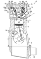
- FIG. 1 shows a schematic configuration of an engine 2 provided with a cam journal lubricating oil supply mechanism according to an exemplary embodiment.
- the engine 2 is an in-line four-cylinder gasoline engine in which four cylinders 8 are arranged in series in a direction perpendicular to the paper surface of FIG. 1 and is mounted on a vehicle such as an automobile.
- a cylinder head 4 In the engine 2, a cylinder head 4, a cylinder block 5, a crankcase 6 and an oil pan 7 are connected vertically.
- the cylinder block 5 is provided with four cylinders 8.
- a piston 9 slidable with respect to the inner peripheral surface of each cylinder 8 and a crankshaft 11 rotatably supported by the crankcase 6 are connected to each other. It is connected by a rod 10.
- Each cylinder 8 of the cylinder block 5, the piston 9, and the cylinder head 4 define a combustion chamber 12 for each cylinder 8.
- the cylinder head 4 has a cylinder head main body 4a and a cover 4b separate from the cylinder head 4.
- the cover 4b covers the upper side of the cylinder head body 4a.
- the cylinder head body 4a is provided with two intake ports 13 and exhaust ports 14 that open to the respective combustion chambers 12 for each cylinder 8 (one is shown in FIG. 1).
- Each intake port 13 is provided with an intake valve 15 that opens and closes each intake port 13
- each exhaust port 14 is provided with an exhaust valve 16 that opens and closes each exhaust port 14.
- the intake valve 15 and the exhaust valve 16 are opened and closed by cam pieces 19 a and 20 a provided on the outer periphery of the rotating intake side camshaft 19 and exhaust side camshaft 20.
- Swing arms 21 and 22 are disposed between the intake valve 13 and the exhaust valve 14 and the cam pieces 19a and 20a, respectively.
- One end portions of the swing arms 21 and 22 are supported by the top portions of pivot mechanisms 24a and 25a of hydraulic lash adjusters (hereinafter referred to as HLA) 24 and 25, respectively.
- HLA hydraulic lash adjusters
- the swing arms 21 and 22 are configured such that cam followers 21a and 22a, which are rotatably provided at substantially central portions of the swing arms 21 and 22, are pushed downward by the top portions of the cam pieces 19a and 20a, respectively, and the pivot mechanisms 24a and 25a of the HLA 24 and 25 are Swing around the top.
- the swing arms 21 and 22 open the intake valve 15 and the exhaust valve 16 at the other end against the urging force of the valve springs 17 and 18, respectively (downward in FIG. 1).
- the HLAs 24 and 25 automatically adjust the valve clearance to zero by hydraulic pressure.
- the HLA 24 and 25 provided in some cylinders 8 of the four cylinders 8 have a valve stop mechanism that deactivates the intake valve 15 and the exhaust valve 16 even if the swing arms 21 and 22 swing. May be provided.
- the cylinder head 4 includes a plurality (four in the present exemplary embodiment) of intake side cam journal bearings 73 (see FIGS. 2 and 3) and a plurality (four in the present exemplary embodiment) of exhaust.
- a side cam journal bearing portion 74 (see FIGS. 2, 3 and 6) is provided.
- head side bearings 73a constituting the lower half of the four intake side cam journal bearings 73 (see FIG. 2) and under the four exhaust side cam journal bearings 74, respectively.
- Four head-side bearing portions 74a constituting the respective halves are formed integrally with the cylinder head body 4a.
- each exhaust-side cam journal bearing portion 74 is constituted by a cam cap-side bearing portion 74b formed on the cam cap 101 as will be described later.
- the upper half of the intake-side cam journal bearing portion 73 is also configured by a cam cap-side bearing portion formed on a cam cap (not shown).
- the head-side bearing portions 73a and 74a may be formed of a member separate from the cylinder head body 4a.
- the intake camshaft 19 includes four cam journals provided on the intake camshaft 19 (in FIG. 3, only the cam journal 72 of the exhaust camshaft 20 is shown, and the cam journal of the intake camshaft 19 is omitted). Are supported on the intake-side cam journal bearing 73. Further, the exhaust side camshaft 20 is pivotally supported on the exhaust side cam journal bearing portion 74 by four cam journals 72 provided on the exhaust side camshaft 20.
- a main gallery 54 extending in the cylinder row direction is provided in the side wall on the exhaust side of the cylinder 8 in the cylinder block 5.
- an oil jet 28 for piston cooling communicating with the main gallery 54 is provided for each piston 9 (for each cylinder 8).
- Each oil jet 28 has a nozzle portion 28a disposed on the lower side of the piston 9, and injects engine oil (hereinafter simply referred to as oil) from the nozzle portion 28a toward the back surface of the top portion of the piston 9. It is configured.
- An intake side internal oil passage 61 extending in the cylinder row direction is provided in the vicinity of the HLA 24 in the cylinder head 4, and an exhaust side internal oil passage 62 extending in the cylinder row direction in the vicinity of the HLA 25 in the cylinder head 4.
- the intake side and exhaust side internal oil passages 61 and 62 correspond to internal oil passages formed in the cylinder head 4.
- the intake side and exhaust side internal oil passages 61 and 62 supply oil to the HLAs 24 and 25, respectively, and have a role of circulating oil to intake side and exhaust side camshaft oil supply passages 67 and 68, which will be described later. .
- An intake-side camshaft oiling passage 65 extending in the axial direction of the intake-side camshaft 19 is provided at a position above the intake-side camshaft 19 and below the cover 4b.
- An exhaust side camshaft oil supply passage 66 extending in the axial direction of the exhaust side camshaft 20 is provided at a position on the upper side and below the cover 4b.
- the intake-side camshaft oil supply passage 65 is an oil supply for supplying the oil as the lubricant to the intake-side cam journal bearing portion 73 that rotatably supports the cam journal of the intake-side camshaft 19. It forms part of the road.
- the oil supply passage 66 for the exhaust side camshaft is used to supply the oil as the lubricating oil to the exhaust side cam journal bearing portion 74 (see FIG. 2) that rotatably supports the cam journal 72 of the exhaust side camshaft 20. It constitutes a part of the oil supply path.
- An intake side oil shower oil passage 29 is provided above the intake side camshaft 19 (below the cover 4b), and exhaust side oil is provided above the exhaust side camshaft 20 (below the cover 4b).
- a shower oil passage 30 is provided.
- the intake-side oil shower oil passage 29 corresponds to a cam-piece oil supply passage that supplies the oil as lubricating oil to the cam piece 19 a of the intake-side cam shaft 19.
- the exhaust-side oil shower oil passage 30 corresponds to a cam piece oil supply passage that supplies the oil as lubricating oil to the cam piece 20 a of the exhaust cam shaft 20.
- the intake-side and exhaust-side oil shower oil passages 29, 30 are provided with cam pieces 19a, 20a located below the intake-side and exhaust-side oil shower oil passages 29, 30 from their downstream ends, and further below The oil is dropped onto the contact portions between the swing arms 21 and 22 and the cam followers 21a and 22a located at the position.
- an oil pump 36 disposed in the engine 2 is connected to the oil supply passage 50, and oil discharged by the oil pump 36 passes through the oil supply passage 50 and covers the engine 2. Supplied to the lubrication part.
- the oil pump 36 is driven by the rotation of the crankshaft 11 of the engine 2 and has a variable capacity capable of changing the oil discharge amount by the pressure input to the pressure chamber of the oil pump 36. This is a type of mechanical oil pump.
- the oil pump 36 may be a normal mechanical oil pump whose oil discharge amount is changed only by the rotation speed of the engine 2 or an electric oil pump.
- the oil supply passage 50 is formed of a pipe, a member connected to the pipe, and the like in addition to the passage formed in the cylinder head 4 and the cylinder block 5, as will be described in detail later.
- the oil supply passage 50 is connected to the oil pump 36 and extends from the oil pump 36 to the junction 54 a with the main gallery 54 in the cylinder block 5, and extends in the cylinder row direction in the cylinder block 5.
- the main gallery 54, the second communication passage 52 extending from the branch point 54b on the main gallery 54 to the cylinder head 4 in the cylinder block 5, and the cylinder head 4 substantially perpendicular to the cylinder row direction and substantially horizontal.
- a third communication passage 53 that extends, and an intake side internal oil passage 61 that is connected to an intake side end of the third communication passage 53 and extends in the cylinder row direction in a portion on the intake side in the cylinder head 4;
- the exhaust-side internal oil passage 62 connected to the exhaust-side end of the passage 53 and extending in the cylinder row direction through the exhaust-side portion in the cylinder head 4
- An intake-side camshaft connecting oil passage 63 connected to the downstream end of the intake-side internal oil passage 61 and passing above the intake-side camshaft 19 and extending toward the exhaust side of the cylinder head 4;
- An exhaust side camshaft communication oil passage 64 connected to the downstream end of the side internal oil passage 62 and passing above the exhaust side camshaft 20 and extending to the intake side of the cylinder head 4, and an intake side camshaft
- An intake side camshaft oil supply passage 65 that extends in the axial direction of the intake side camshaft 19 at a position above the intake side camshaft 19, and an exhaust side cams
- An exhaust side camshaft oil supply passage 66 that extends in the axial direction of the exhaust side camshaft 20 at a position above the exhaust side camshaft 20 and branches from the intake side camshaft oil supply passage 65 and has four intake sides.
- An intake side position restricting journal branch oil passage 69 connected to an intake side position restricting journal bearing portion 75 that rotatably supports a journal (not shown), and an exhaust side camshaft connecting oil passage 64 (more specifically, exhaust gas) Branching from the connecting oil passage 64b for the side cam shaft and the exhaust side internal oil passage 62), the position regulating journal 76 (see FIG. 3) formed on the exhaust side cam shaft 20 is rotatably supported.
- An oil strainer 39 facing the oil pan 7 is connected to the suction port of the oil pump 36.
- An oil filter 37 and an oil cooler 38 (also shown in FIG. 1) are arranged in order from the upstream side to the downstream side in the first communication passage 51 communicating with the discharge port of the oil pump 36.
- the stored oil is pumped up by the oil pump 36 through the oil strainer 39, filtered by the oil filter 37, cooled by the oil cooler 38, and then introduced into the main gallery 54 in the cylinder block 5.
- the main gallery 54 includes the oil jet 28 for injecting cooling oil to the back side of the four pistons 9, an oil supply unit 41 to metal bearings arranged in five crank journals in the crankshaft 11, It is connected to an oil supply portion 42 to a bearing ring disposed on the crank pin of the crankshaft 11 that rotatably connects the two connecting rods 10, and oil is always supplied to the main gallery 54.
- An oil supply unit 43 that supplies oil to the hydraulic chain tensioner and an oil passage 40 that supplies oil to the pressure chamber of the oil pump 36 via the linear solenoid valve 49 are provided at a branch point 54 c on the main gallery 54. It is connected.
- the exhaust side internal oil passage 62 is connected to the HLA 25.
- the exhaust-side camshaft communication oil passage 64 connected to the exhaust-side internal oil passage 62 supplies oil that has passed through the exhaust-side internal oil passage 62 to the exhaust-side camshaft oil supply passage 66.
- Four exhaust side cam journal branch oil passages 68 are branched from the exhaust side cam shaft oil supply passage 66.
- the four exhaust-side cam journal branch oil passages 68 are connected to the four exhaust-side cam journal bearing portions 74, respectively, and supply oil to the exhaust-side cam journal bearing portions 74, respectively.
- two exhaust side oil shower oil passages 30 are connected to each exhaust side cam journal branch oil passage 68.
- the branch side oil passage 70 for the exhaust side position regulation journal is connected to the exhaust side position regulation journal bearing part 78 and supplies oil to the exhaust side position regulation journal bearing part 78. Oil is always supplied to the oil passages 30, 62, 64, 66, 68 and 70 on the exhaust side.
- the oil supply path on the intake side of the cylinder head 4 is the same as the oil supply path on the exhaust side.
- the intake side internal oil passage 61 is connected to the HLA 24.
- the intake-side camshaft communication oil passage 63 connected to the intake-side internal oil passage 61 supplies oil that has passed through the intake-side internal oil passage 61 to the intake-side camshaft oil supply passage 65.
- Four intake-side cam journal branch oil passages 67 are branched from the intake-side camshaft oil supply passage 65.
- the four intake-side cam journal branch oil passages 67 are respectively connected to the four intake-side cam journal bearing portions 73 and supply oil to the intake-side cam journal bearing portions 73, respectively.
- two intake-side oil shower oil passages 29 are connected to each intake-side cam journal branch oil passage 67.
- the intake side position restricting journal branch oil passage 69 is connected to the intake side position restricting journal bearing portion 75 and supplies oil to the intake side position restricting journal bearing portion 75. Oil is always supplied to the oil passages 29, 61, 63, 65, 67, and 69 on the intake side.
- the configuration of the intake side and exhaust side cam shafts 19 and 20 disposed in the cylinder head 4 and the supply of oil to the cam journal bearing portions 73 and 74 of the intake side and exhaust side cam shafts 19 and 20 are performed.
- the configuration of the cam journal lubricating oil supply mechanism will be described in detail with reference to FIGS. Since the configuration of the intake side cam shaft 19 and the configuration of the exhaust side cam shaft 20 are substantially the same, in the following description, only the configuration of the exhaust side cam shaft 20 will be described, and the intake side cam shaft 19 will be described. The detailed description of the configuration is omitted.
- the cam journal lubricating oil supply mechanism is provided on each of the intake side and the exhaust side of the cylinder head 4.
- cam journal lubricating oil supply mechanism on the intake side and the cam journal lubricating oil supply on the exhaust side are provided. Since the configuration of the mechanism is substantially the same, in the following description, only the configuration of the cam journal lubricant supply mechanism on the exhaust side will be described, and the configuration of the cam journal lubricant supply mechanism on the intake side will be described. Detailed description thereof will be omitted.
- the exhaust-side camshaft 20 is disposed in the cylinder head 4 (between the cylinder head body 4a and the cover 4b).
- the exhaust-side camshaft 20 swings a plurality of (four in this exemplary embodiment) cam journals 72 rotatably supported by the cylinder head body 4a and the cam cap 101, and the swing arm 22 (see FIG. 1).
- the cam piece 20a and the exhaust-side camshaft 20 are provided at the end of the exhaust-side camshaft 20 in the axial direction or in the vicinity thereof (in the present exemplary embodiment, in the vicinity of the above-mentioned end), And a position restricting journal 76 for restricting the position.
- a timing chain for rotating the exhaust camshaft 20 in accordance with the rotation of the crankshaft 11 is provided at a portion outside the position regulating journal 76 in the axial direction of the exhaust camshaft 20.
- a timing chain sprocket around which is wound.
- a variable valve timing mechanism VVT that changes the timing of rotation of the exhaust camshaft 20 to change the timing of opening and closing of the exhaust valve 14 is also arranged on the portion outside the position control journal 76 in the axial direction. It is installed.
- the cam journals 72 are arranged at equal intervals in the axial direction of the exhaust camshaft 20 so as to correspond to the positions of the four cylinders 8 in the exhaust camshaft 20.
- the four cam journals 72 are moved from the position restricting journal 76 side (left side in FIG. 3) toward the opposite position restricting journal 76 side (right side in FIG. 3), first cam journal 72a, second cam journal 72b, They are referred to as a third cam journal 72c and a fourth cam journal 72d (if they are not distinguished from each other, they may be simply referred to as a cam journal 72).
- the cam journals 72a to 72d are supported by the cylinder head body 4a and the cam cap 101 so as to be sandwiched between the cylinder head body 4a and the cam cap 101 attached and fixed to the cylinder head body 4a.
- the cylinder head body 4a has a semicircular shape as seen from the axial direction of the exhaust cam shaft 20 at positions corresponding to the cam journals 72a to 72d from the upper side to the lower side.
- a plurality of (four in the present exemplary embodiment) head-side bearing portions 74a that are recessed toward the head are formed, while the cam cap 101 has a semicircular shape as viewed from the axial direction.
- a cam cap side bearing portion 74b that is recessed from the side toward the upper side is formed. As shown in FIG.
- the exhaust side cam having a circular shape when viewed from the axial direction is formed by causing the end portions in the circumferential direction of the head side bearing portion 74a and the cam cap side bearing portion 74b to abut each other vertically.
- Journal bearing portions 74 are respectively formed.
- the cam journals 72a to 72d are rotatably supported by the exhaust-side cam journal bearings 74 between the cylinder head body 4a and the cam cap 101 provided for each cam journal 72.
- Each cam cap 101 is brought into contact with the cylinder head body 4a so as to sandwich each cam journal 72, and then fixed to the cylinder head body 4a by two bolts 120 (see FIG. 6). From the upper surface of each cam cap 101, a cylindrical protruding portion 101a protrudes upward. As will be described in detail later, the inside of the projecting portion 101a is a bolt hole, and a bolt 109 for connecting the exhaust-side cam journal branch oil passage 68 to the cam cap 101 is fastened to the bolt hole.
- the cam piece 20 a is adjacent to each cam journal 72 at two portions located on both sides in the axial direction of the exhaust camshaft 20 with respect to each cam journal 72 in the exhaust camshaft 20.
- the same cylinder 8 is set to match the timing of the explosion stroke (exhaust stroke) in each cylinder 8.
- the corresponding cam pieces 20a are arranged so that the positions of the tops are aligned with respect to the circumferential direction of the cam shaft, while the cam pieces 20a corresponding to different cylinders 8 are predetermined in the circumferential direction of the exhaust side cam shaft 20. It is arranged so as to be shifted by an angle of.
- the position regulating journal 76 is formed to have a larger diameter than the cam journals 72a to 72d so that the movement of the exhaust cam shaft 20 in the axial direction can be regulated.
- the position regulation journal 76 is sandwiched between the cylinder head body 4a and the position regulation journal cam cap 108 so as to be sandwiched between the cylinder head body 4a and the position regulation journal cam cap 108 attached and fixed to the cylinder head body 4a. It is supported.
- the portion of the cylinder head body 4 a corresponding to the position regulating journal 76 has a semicircular shape as viewed from the axial direction of the exhaust side camshaft 20.
- the position restricting journal cam cap 108 While the position restricting journal head side bearing portion 78a that is recessed from the upper side to the lower side is formed, the position restricting journal cam cap 108 has a semicircular shape as viewed from the axial direction. A position regulating journal cam cap side bearing portion 78b that is recessed from the lower side toward the upper side is formed. The end portions in the circumferential direction of the head-side bearing portion 78a for the position-regulating journal and the cam-cap side bearing portion 78b for the position-regulating journal are butted up and down, so that the shape seen from the axial direction is circular.
- the exhaust side position regulation journal bearing 78 is formed, and the position regulation journal 76 is sandwiched between the cylinder head body 4a and the position regulation journal cam cap 108 in the exhaust side position regulation journal bearing 78, and is rotatable. Is pivotally supported.
- FIG. 3 shows a position restriction journal head-side bearing portion 75a constituting the lower half of the intake side position restriction journal bearing portion 75, and position restriction constituting the upper half of the intake side position restriction journal bearing portion 75.
- the journal cam cap side bearing is omitted.
- the oil supply passage 50 the first communication passage 51, the main gallery 54, the second communication passage 52, the third communication passage 53, the intake-side internal oil passage 61, the intake-side camshaft communication oil passage 63, and the intake-side camshaft.
- the oil supply passage 65 and the four intake-side cam journal branch oil passages 67 constitute an intake-side cam journal lubricating oil supply mechanism.
- the four exhaust-side cam journal branch oil passages 68 constitute an exhaust-side cam journal lubricating oil supply mechanism.
- the first communication passage 51, the main gallery 54, the second communication passage 52, and the third communication passage 53 are oil supply passages common to the intake and exhaust cam journal lubricant supply mechanisms.
- the oil supply path of the exhaust-side cam journal lubricating oil supply mechanism includes an exhaust-side internal oil path 62, an exhaust-side camshaft communication oil path 64, an exhaust-side camshaft oil supply path 66, and The four exhaust-side cam journal branch oil passages 68 are provided.
- the exhaust-side camshaft oiling passage 66 is positioned above the exhaust-side camshaft 20 and extends in the axial direction of the exhaust-side camshaft 20.
- the exhaust-side camshaft communication oil passage 64 connects the upstream end of the exhaust-side camshaft oil supply passage 66 and an exhaust-side internal oil passage 62 formed in the cylinder head 4.
- the four exhaust-side cam journal branch oil passages 68 branch from four locations (positions corresponding to the cam journals 72a to 72d) of the exhaust-side camshaft oil supply passage 66, respectively, and the four cam journal bearing portions 74 have upper sides thereof. Are respectively connected to supply oil to the four cam journal bearing portions 74.
- Each exhaust-side cam journal branch oil passage 68 extends from the exhaust-side cam shaft oil supply passage 66 toward the cam journal 72 corresponding to the exhaust-side cam journal branch oil passage 68 in the axial direction of the exhaust-side cam shaft 20. Extends in the vertical horizontal direction.
- two exhaust-side oil shower oil passages 30 are connected to each exhaust-side cam journal branch oil passage 68 as described above.
- Two exhaust-side oil shower oil passages 30 connected to each exhaust-side cam journal branch oil passage 68 are connected to the cam journal 72 corresponding to the exhaust-side cam journal branch oil passage 68 with respect to the exhaust-side cam shaft 20. It extends in the axial direction toward the two cam pieces 20a located on both sides in the axial direction.
- an exhaust-side position regulating journal branch oil passage 70 connected to the exhaust-side position regulating journal bearing portion 78 branches from the exhaust-side camshaft communication oil passage 64 (specifically, the connecting portion 64b). Yes.
- the exhaust-side camshaft communication oil passage 64, the exhaust-side camshaft oil supply passage 66, and the exhaust-side cam journal branch oil passage 68 are attached to the cylinder head 4 (cylinder head body 4a) and are separate from the cylinder head 4. It is the oil supply path formed with the member of the body.
- the exhaust-side oil shower oil passage 30 and the exhaust-side position regulating journal branch oil passage 70 are also formed by members separate from the cylinder head 4.
- the exhaust-side camshaft connecting oil passage 64 includes a pipe 64a bent in a substantially L shape, and a cylindrical connection member 64d for connecting the pipe 64a and the exhaust-side internal oil passage 62. Is formed by. That is, the exhaust-side camshaft communication oil passage 64 includes an oil passage 64c in the pipe 64a and the connection portion 64b formed in the connection member 64d.
- the connecting member 64d is divided into two upper and lower parts, but these two divided parts are finally stacked one above the other and integrated with each other. Further, the connection portion 64b is opened on the upper surface of the connection member 64d (the upper surface of the upper divided portion), and this opening is covered with a blocking member (not shown).
- the exhaust-side camshaft oil supply passage 66 is formed by a pipe 66a and a plurality of (four in the present exemplary embodiment) T-shaped joints 102 provided on the pipe 66a. That is, the exhaust-side camshaft oil supply passage 66 includes an oil passage 66c in the pipe 66a and an oil passage 66b (see FIG. 5) extending in the axial direction of the exhaust-side camshaft 20 in the joint 102.
- the pipe 66a is cut at the joint 102 and is divided into a plurality of divided pipes.
- each exhaust-side cam journal branch oil passage 68 connects a pipe 68 a, a joint 102, and a downstream end of each exhaust-side cam journal branch oil passage 68 to the cam cap 101. And a fixing member 103 for this purpose. That is, each exhaust-side cam journal branch oil passage 68 is formed in an oil passage 68d in the pipe 68a, an oil passage 68b extending in the horizontal direction perpendicular to the axial direction in the joint 102, and the fixed member 103. And an oil passage 68c.
- Each exhaust-side oil shower oil passage 30 is formed by a pipe 30a.
- the pipe 30a is integrally coupled to the pipe 68a.
- the exhaust side position restricting journal branch oil passage 70 is formed by a position restricting journal cam cap 108 attached and fixed to the cylinder head body 4a, as will be described later.
- the four joints 102 respectively corresponding to the four exhaust-side cam journal branch oil passages 68 are moved from the position restricting journal 76 side toward the counter-position restricting journal 76 side.
- 102b, the third joint 102c, and the fourth joint 102d (in the case where these are not distinguished, they may be simply referred to as the joint 102).
- Each joint 102 is integrally coupled to a pipe 66a and a pipe 68a that forms part of each exhaust cam journal branch oil passage 68 (the first joint 102a is also integrally coupled to the pipe 64a). Have been).
- Each fixing member 103 is integrally coupled to each pipe 68a.
- various methods such as welding can be applied. In particular, bonding by brazing is desirable.
- the brazing material is attached to the pipes 66a and 68a (the first joint 102a also includes the pipe 64a (hereinafter the same)), and the pipes 66a and 68a are joined to the joint 102. And inserted into the fixing member 103.
- the brazing material is disposed at the joint between the pipes 66a and 68a and the joint 102, and the joint between the pipe 68a and the fixing member 103, and the joint is heated, so that the brazing material is disposed at the pipe 66a. , 68a and the joint 102 and the gap between the pipe 68a and the fixing member 103. Accordingly, the pipes 66a and 68a and the joint 102, and the pipe 68a and the fixing member 103 are integrally coupled to each other by brazing. In the heating, each of the joints may be heated one by one, but if all the joints are heated at the same time in an oven or the like, the manufacturing can be simplified.
- the downstream end of the exhaust-side internal oil passage 62 opens at a position near the position regulating journal 76 on the upper surface of the cylinder head body 4a.
- the connection member 64d is fixed around the opening of the exhaust side internal oil passage 62 on the upper surface of the cylinder head body 4a.
- the exhaust side internal oil passage 62 is connected to the upstream end of the exhaust side camshaft communication oil passage 64 via the connection portion 64b (connection member 64d).
- the pipe 64a constituting the exhaust side camshaft communication oil passage 64 passes from the connecting member 64d in the vicinity of the position regulating journal 76 in the axial direction inside the exhaust side camshaft 20 and above the exhaust side camshaft 20. Then, after extending obliquely upward toward the intake side, it is curved so as to be parallel to the axial direction and extends in the axial direction.
- a first joint 102a is connected to the downstream end of the pipe 64a.
- a pipe 66a is connected to the end of the first joint 102a opposite to the pipe 64a.
- the pipe 64a extends vertically upward from the connection member 64d, and then bends at a substantially right angle toward the intake side, so that the upper side of the exhaust camshaft 20 is substantially orthogonal to the axial direction. It may be shaped so as to extend horizontally, and then bend so as to be parallel to the axial direction and extend in the axial direction.
- the second to fourth joints 102b to 102d connect the divided pipes in the pipe 66a to each other.
- the downstream end portion of the pipe 66a (the downstream end portion of the split pipe located downstream of the fourth joint 102d) is crushed so that the end portion is closed.
- an oil passage 66b constituting a part of the oil supply passage 66 for the exhaust side camshaft, and the exhaust side cam
- An oil passage 68 b constituting a part of the journal branch oil passage 68 is formed.
- the oil passage 66b in the first joint 102a communicates with the downstream end of the exhaust side camshaft communication oil passage 64 (the oil passage 64c in the pipe 64a) and the oil passage 66c in the pipe 66a.
- the oil passages 66b in the second to fourth joints 102b to 102d communicate with the oil passages 66c in the two adjacent divided pipes in the pipe 66a.
- Each exhaust-side cam journal branch oil passage 68 (oil passage 68b) is branched from each exhaust-side camshaft oil supply passage 66 (oil passage 66b) in each joint 102.
- the upstream end of the pipe 68 a constituting the exhaust-side cam journal branch oil passage 68 is connected to the joint 102, while the downstream end is connected to the fixing member 103.
- the oil passage 68d in the pipe 68a communicates with the oil passage 68b and the oil passage 68c in the fixing member 103, respectively.
- Each fixing member 103 has a connecting portion 104 connected to the pipe 68 a and a ring-shaped fixing portion 105 fixed on the cam cap 101.
- An end portion on the downstream side of the branch cam passage 68 for the exhaust side cam journal faces the inside of the fixed portion 105.
- Inside the fixing portion 105 is a bolt hole, and a bolt 109 for fixing the fixing member 103 to the cam cap 101 and connecting the exhaust side cam journal branch oil passage 68 to the cam cap 101 is provided in the bolt hole. It is concluded.
- Each exhaust-side cam journal branch oil passage 68 (pipe 68 a) is connected to each cam cap 101 by each fixing member 103.
- the fixing portion 105 of the fixing member 103 is placed on the protruding portion 101a of each cam cap 101 so that the bolt hole of the protruding portion 101a and the bolt hole of the fixing portion 105 communicate with each other vertically. Later, the bolt 109 is screwed into the bolt hole of the protruding portion 101a and the bolt hole of the fixing portion 105, and the cam cap 101 and the fixing member 103 are fastened.
- the exhaust-side cam journal branch oil passage 68 By connecting each exhaust-side cam journal branch oil passage 68 to the cam cap 101, the exhaust-side cam shaft oil supply passage 66 is also fixed to the cam cap 101 via each joint 102.
- the members (pipe 64a, connecting member 64d, pipe 66a, joint 102, pipe forming the exhaust side camshaft oil supply passage 66, exhaust side camshaft communication oil passage 64, and exhaust side cam journal branch oil passage 68 are formed.
- 68a and the fixing member 103) are attached or fixed to the cylinder head 4 (cylinder head body 4a) directly or indirectly.
- the connecting member 64d and the fixing members 103 the oil cam passage 66 for the exhaust-side camshaft having a particularly long length.
- the vibration associated with the vibration of the engine 2 can be suppressed.
- the pipe 30a which forms each exhaust side oil shower oil path 30 is indirectly fixed to the cylinder head 4 (cylinder head main body 4a).
- each exhaust-side cam journal branch oil passage 68 is connected to each exhaust-side cam journal bearing portion 74 from the upper side (directly above in the present exemplary embodiment) via the bolt oil passage 71. It will be.
- the oil that has flowed from the exhaust-side camshaft oil supply passage 66 into the oil passage 68b in the exhaust-side cam journal branch oil passage 68 in the joint 102 is oil passage 68d in the pipe 68a and oil passage in the fixing member 103. It flows into the bolt oil passage 71 through 68c. The oil flowing into the bolt internal oil passage 71 is supplied to the exhaust cam journal bearing portion 74 through the bolt internal oil passage 71. The oil thus flowing into the oil passage 68b is supplied to the exhaust side cam journal bearing portion 74 from the upper side (directly above).
- an oil groove 80 formed so as to be recessed upward is provided in an upper portion of each cam cap side bearing portion 74 b, and each exhaust side cam journal branch oil passage 68 is provided. Is connected to the uppermost portion of the oil groove 80.
- the oil supplied to the exhaust side cam journal bearing portion 74 (the uppermost portion of the oil groove 80) spreads throughout the oil groove 80. Then, when the exhaust side camshaft 20 rotates according to the rotation of the crankshaft 11, the oil spreads from the oil groove 80 to the entire exhaust side cam journal bearing portion 74, and thus the exhaust side cam journal bearing portion 74 as a whole.
- An oil film is formed.
- Each exhaust-side cam journal branch oil passage 68 is provided with a narrowed portion 168 whose flow-path cross-sectional area is narrower than that of the exhaust-side camshaft oil supply passage 66.
- the flow passage cross-sectional area of the oil passage 66 b of the exhaust side camshaft 66 is branched from the exhaust side camshaft oil passage 66.
- a narrowed portion 168 narrower than the channel cross-sectional area is provided.
- the flow passage cross-sectional area means the area of a cross section cut in a direction perpendicular to the oil flow direction.
- the flow passage cross-sectional area of the throttle portion 168 does not depend on the rotational speed of the oil pump 36 or the oil temperature, in other words, regardless of the oil discharge pressure or the oil viscosity.
- the cross-sectional area of the flow path is such that a uniform hydraulic pressure (a uniform amount of oil) is supplied to all of the bearing portions 74.
- the flow passage cross-sectional area of the throttle portion 168 is such that after the exhaust side camshaft oil supply passage 66 is filled with oil, the oil pressure in the exhaust side camshaft oil supply passage 66 passes through the throttle portion 168.
- the flow passage cross-sectional area is such that oil flows into each exhaust-side cam journal branch oil passage 68 when the hydraulic pressure becomes as high as possible.
- each exhaust-side cam journal branch oil passage 68 a portion upstream of the downstream end and downstream of the throttle portion 168 serves as a cam piece oil supply passage.
- Two exhaust-side oil shower oil passages 30 are branched (in FIG. 3, the exhaust-side oil shower oil passage 30 is omitted). These two exhaust-side oil shower oil passages 30 are connected to the cam journal 72 corresponding to the exhaust-side cam journal branch oil passage 68 from each exhaust-side cam journal branch oil passage 68. It extends in the axial direction toward the two cam pieces 20a located on both sides in the direction.
- the oil passage 68 c in the fixed member 103 is provided with a portion having a smaller channel cross-sectional area than the exhaust side oil shower oil passage 30. As a result, oil can easily flow into the exhaust oil shower oil passages 30 from the branch cam passage 68 for the exhaust cam journal.
- the branch-side oil passage 70 for the exhaust-side position regulating journal is located from the uppermost portion of the exhaust-side camshaft 20 in the exhaust-side camshaft communication oil passage 64 so that it is positioned below the uppermost portion of the exhaust-side camshaft 20 Is also branched from a portion located on the lower side (in this exemplary embodiment, a connecting portion 64b between the exhaust-side camshaft communication oil passage 64 and the exhaust-side internal oil passage 62). As shown in FIG. 7, the exhaust side position regulating journal branch oil passage 70 is formed in the position regulating journal cam cap 108.
- the downstream end of the branch oil passage 70 for the exhaust side position restricting journal communicates with an oil groove 81 for the position restricting journal provided in the cam cap side bearing portion 78b for the position restricting journal of the cam cap 108 for the position restricting journal.
- the oil groove 81 for position restriction journal is the same as the oil groove 80 of the exhaust cam journal bearing portion 74.
- the downstream end portion of the branch position oil passage 70 for the exhaust side position restricting journal is not the uppermost portion of the oil groove 81 for the position restricting journal, but a lower portion (in the present embodiment, the lowermost portion). It is connected.
- the downstream portion of the exhaust side position regulating journal branch oil passage 70 is provided with a throttle portion 170 having a narrower channel cross-sectional area than the upstream portion thereof.
- the oil pressure in the exhaust side camshaft communication oil passage 66 is not high enough to allow the oil to pass through the throttle portion 170, the oil passes through the exhaust side position regulating journal branch oil passage 70 to the exhaust side.
- the position regulation journal bearing portion 78 is not supplied.
- the oil in the exhaust side camshaft communication oil passage 64 is unlikely to decrease because the oil is once clogged at the throttle portion 170.
- oil can be supplied to the exhaust-side camshaft oil supply passage 66 and the exhaust-side cam journal oil supply passage 68 through the exhaust-side camshaft communication oil passage 64.
- “cam journal 72” is read as “cam journal of the intake-side cam shaft 19” and “exhaust-side cam shaft 19”.
- “Journal bearing portion 74” is read as “intake side cam journal bearing portion 73”
- “Position restriction journal 76” is read as “Position restriction journal of intake side camshaft 19”
- “Exhaust side internal oil passage 62” is read as “Intake air”.
- the cylinder head 4 is provided with various devices such as a fuel injection device and a spark plug. Therefore, the cylinder head body 4a is provided with a fuel injection device mounting portion (not shown) and a spark plug mounting portion (not shown) for each cylinder 8. For example, when precise combustion control is required in order to improve the thermal efficiency of the engine, two spark plugs may be attached, so that the attachment part is also provided according to the number of devices.
- an attachment portion for attaching each device is formed so as to avoid an oil supply path or the like formed in the cylinder head body 4 a, and the above oil supply Each device must be arranged so as to avoid roads. Therefore, when the oil supply passage is formed in a complicated manner in the cylinder head body 4a, it is difficult to add the device to the cylinder head 4.
- the exhaust-side camshaft oil supply passage 66, the exhaust-side camshaft communication oil passage 64, and the exhaust-side cam journal branch oil passage 68 are configured by members different from the cylinder head 4, respectively.
- oil is supplied to each exhaust-side cam journal bearing portion 74 from above.
- it is not necessary to form an oil supply passage communicating with the exhaust side cam journal bearing portion 74 in the cylinder head 4.
- the oil supply passage communicating with the intake-side cam journal bearing 73 is provided in the cylinder head body. It is not necessary to form in 4a.
- an attachment portion for attaching the device can be easily formed in the cylinder head body 4a, and the devices to be added can be arranged in the cylinder head 4 relatively easily. Therefore, it is possible to easily cope with an increase in devices disposed in the cylinder head 4.
- the oil when the oil is supplied to the cam journal bearing portions 73 and 74 from the upper side as in the present exemplary embodiment, the oil is raised to the upper side of the intake side and the exhaust side cam shafts 19 and 20 and then the intake air is supplied. Since it is necessary to flow into the oil supply passages 65 and 66 for the side and exhaust side camshafts, the oil flow rate (hydraulic pressure) decreases toward the downstream side of the intake side and exhaust side camshaft oil supply passages 65 and 66, and a plurality of ( There is a possibility that variations occur in the hydraulic pressure supplied to the four (4) intake-side cam journal bearing portions 73 and the hydraulic pressure supplied to the plural (four) intake-side cam journal bearing portions 74.
- each exhaust-side cam journal branch oil passage 68 has a flow path at a portion branched from the exhaust-side cam shaft oil supply passage 66 rather than the exhaust-side cam shaft oil supply passage 66. Since the throttle section 168 having a small cross-sectional area is provided, if the oil pressure in the exhaust-side camshaft oil supply passage 66 does not reach a hydraulic pressure that allows oil to pass through the throttle section 168, four exhaust-side cam journal branches Oil is not supplied to the four exhaust side cam journal bearing portions 74 via the oil passage 68.
- the oil is supplied to the exhaust side cam journal bearing portion 74 (for example, the exhaust side cam journal bearing portion 74 that supports the first cam journal 72a) connected to the upstream side portion of the exhaust side camshaft oil supply passage 66.
- Supply of oil to the exhaust-side cam journal bearing portion 74 (for example, the exhaust-side cam journal bearing portion 74 that supports the fourth cam journal 72d) connected to the downstream portion of the exhaust-side camshaft oil supply passage 66 is performed. Rather than being performed prior to the supply, the entire exhaust side camshaft oil supply passage 66 is filled with oil, and the oil pressure in the exhaust side camshaft oil supply passage 66 causes the oil to flow through the throttle portion 168.
- each exhaust-side cam journal branch oil passage 68 in each exhaust-side cam journal branch oil passage 68, the upstream side of the downstream end and the downstream side of the throttle 168 toward the two cam pieces 20 a.
- the two exhaust-side oil shower oil passages 30 extending in the axial direction are branched.
- two intake-side oil shower oil passages 29 are branched from each intake-side cam journal branch oil passage 67.
- the cam journal bearing portions 73 and 74 are configured to supply oil from the upper side thereof, and the intake side and exhaust side oil shower oil passages 29 and 30 are connected to the intake side and exhaust side cam journal branch oil passages 67 and 68.
- the intake-side and exhaust-side oil shower oil passages 29, 30 can be easily disposed above the cam pieces 19a, 20a.
- the exhaust side position regulating journal branch oil passage 70 for supplying oil to the exhaust side position regulating journal bearing portion 78 includes the exhaust side camshaft communication oil passage 64 and the exhaust side internal oil. It is branched from the connection portion 64b to the passage 62 and is located below the exhaust side camshaft 20, and the configuration of the intake side cam journal lubricant supply mechanism is the same as that of the exhaust side cam journal lubricant supply mechanism. The configuration is the same as the configuration. Thereby, the engine 2 can be made into a compact structure.
- the position regulating journal 76 is formed to have a larger diameter than the cam journal 72, and therefore the exhaust gas is exhausted from the exhaust side cam shaft oil supply passage 66.
- the branch oil passage 70 for the side position regulating journal is branched and oil is supplied to the exhaust side position regulating journal bearing portion 78 from the upper side
- the height position of the exhaust side camshaft oil supply passage 66 is set to the position regulating journal. It must be increased to match the diameter of 76. If the position of the exhaust-side camshaft oiling passage 66 is increased, the size of the cover 4b in the vertical direction needs to be increased. Thereby, the magnitude
- the exhaust side position regulating journal branch oil passage 70 is branched from the connection portion 64b between the exhaust side camshaft communication oil passage 64 and the exhaust side internal oil passage 62, and exhaust gas is discharged.
- the branch oil passage 70 for the side position regulating journal is positioned below the uppermost part of the exhaust cam shaft 20.
- the branch side oil passage 69 for the intake side position restriction journal is branched from the connecting portion 63a between the communication oil path 63 for the intake side camshaft and the intake side internal oil passage 61, so that the branch oil passage for the intake side position restriction journal is branched. 69 is positioned below the uppermost portion of the intake side camshaft 19.
- the lengths of the branch oil passages 69 and 70 for the intake side and exhaust side position regulating journals can be shortened.
- the exhaust-side camshaft oil supply passage 66 is positioned on the intake side of the exhaust-side camshaft 20, and the intake-side camshaft oil supply passage 65 is exhausted from the intake-side camshaft 19.
- the present invention is not limited to this, and the exhaust-side camshaft oil supply passage 66 is located on the exhaust side of the exhaust-side camshaft 20, and the intake-side camshaft oil supply passage 65 is connected to the intake-side camshaft. It may be located on the intake side with respect to 19.
- the exhaust side camshaft oil supply passage 66, the exhaust side camshaft communication oil passage 64, and the exhaust side cam journal branch oil passage 68 include the pipe 64a, the connecting member 64d, the pipe 66a, and the joint. 102, the pipe 68a, and the fixing member 103.
- the present invention is not limited to this, and any member may be used as long as it is a separate member from the cylinder head 4 and can form an oil passage. It may be.
- two intake-side oil shower oil passages 29 branch from each intake-side cam journal branch oil passage 67, and two exhaust-side oil showers from each exhaust-side cam journal branch oil passage 68.
- the oil passage 30 is branched, it is not limited to this.
- One exhaust oil shower oil passage 30 is branched from the side cam journal branch oil passage 68 so as to extend in the axial direction of the exhaust cam shaft 20 toward the cam piece 20. The same applies to the intake-side oil shower oil passage 29.
- the throttle portion 168 branches from the exhaust camshaft oil passage 66 in the oil passage 66 b formed in the joint 102 in each exhaust cam journal branch oil passage 68.
- the present invention is not limited to this, and the throttle portion 168 is provided in a portion (for example, in the pipe 66a) other than the portion branched from the exhaust-side camshaft oil supply passage 66 in the exhaust-side cam journal branch oil passage 68. It may be provided.
- the intake side position restricting journal branch oil passage 69 branches from the connection portion 63a between the intake side camshaft connecting oil passage 63 and the intake side internal oil passage 61, and the exhaust side position restricting.
- the journal branch oil passage 70 branches off from a connecting portion 64b between the exhaust side camshaft communication oil passage 64 and the exhaust side internal oil passage 62.
- the present invention is not limited to this, and is used for the intake side and exhaust side position regulating journals. If the branch oil passages 69 and 70 are located below the uppermost portions of the intake side and exhaust side cam shafts 19 and 20, from which part of the communication oil passages 63 and 64 for the intake side and exhaust side cam shafts It may be branched. Further, the present invention is applied even if the intake side and exhaust side position regulating journal branch oil passages 69 and 70 are positioned above the uppermost portions of the intake side and exhaust side cam shafts 19 and 20. Is possible.
- the present invention relates to a camshaft for an engine having a camshaft disposed in a cylinder head and having a plurality of cam journals, and a plurality of cam journal bearing portions for rotatably supporting the plurality of cam journals of the camshaft.
Landscapes
- Engineering & Computer Science (AREA)
- Mechanical Engineering (AREA)
- General Engineering & Computer Science (AREA)
- Lubrication Of Internal Combustion Engines (AREA)
- Valve-Gear Or Valve Arrangements (AREA)
Abstract
シリンダヘッド(4)とは別体の部材で形成され、潤滑油を複数のカムジャーナル軸受部(73,74)に供給するための給油路が、カム軸(19,20)よりも上側に位置するカム軸用給油路(66)と、該カム軸用給油路とシリンダヘッド(4)内の内部油路(61,62)との間に設けられたカム軸用連絡油路(64)と、上記カム軸用給油路からそれぞれ分岐しかつ複数のカムジャーナル軸受部(73,74)に上側からそれぞれ接続された複数のカムジャーナル用分岐油路(67,68)とを有し、該複数のカムジャーナル用分岐油路が、上記カム軸用給油路よりも流路断面積の小さい絞り部(168)をそれぞれ有している。
Description
本発明は、エンジンのカムジャーナル潤滑油供給機構に関する。
従来より、シリンダヘッドに配設されかつ複数のカムジャーナルを有するカム軸と、該カム軸の該複数のカムジャーナルを回転可能にそれぞれ支持するカムジャーナル軸受部とを有するエンジンにおいて、該複数のカムジャーナル軸受部に潤滑油を供給するカムジャーナル潤滑油供給機構が知られている。
特許文献1には、シリンダヘッド内に形成されたオイルギャラリから上側に延びて、カムジャーナル軸受部の下側の部分と接続されたカムジャーナル用油路を備え、該カムジャーナル用油路を通じて、カムジャーナル軸受部にその下側から潤滑油を供給するカムジャーナル潤滑油供給機構が開示されている。
また、特許文献2には、油圧源からの潤滑油を複数のカムジャーナル軸受部のうちの1つに案内する第1の油路と、該第1の油路が接続されたカムジャーナル軸受部に対して回転摺動する、カム軸のカムジャーナルを貫通して、該カム軸の回転に伴って間欠的に潤滑油が供給される第2の油路と、上記カムジャーナルよりも上側に配置されかつ上記第2の油路から供給された潤滑油を上記カム軸よりも上側から他のカムジャーナル軸受部に供給する第3の油路とを備えたカムジャーナル潤滑油供給機構が開示されている。
ところで、シリンダヘッドには、カム軸以外にも、燃料噴射装置や点火プラグなど種々のデバイスが配設される。例えば、エンジンの熱効率を改善するために緻密な燃焼制御が要求される場合に、点火プラグの数を増やすことがあり、このようにデバイスの増設が要求されることが多くある。
この要求を満たすべくシリンダヘッドにデバイスを増設する場合には、各デバイスを、シリンダヘッド内に形成された給油路やウォータジャケットを避けるようにして配置しなければならない。
特許文献1に記載のようなカムジャーナル軸受部にその下側から潤滑油を供給するカムジャーナル潤滑油供給機構では、シリンダヘッドに、カムジャーナル軸受部に接続される油路を設ける必要があり、該油路の分だけ、シリンダヘッドへの上記デバイスの配設可能な領域が狭くなるため、上記デバイスの増設が困難になる。
一方、特許文献2に記載のカムジャーナル潤滑油供給機構のように、カムジャーナルよりも上側からカムジャーナル軸受部に潤滑油を供給するようにすれば、シリンダヘッド内に設ける油路の数を減少させることができるため、上記デバイスの増設が比較的容易になる。
しかしながら、特許文献2に記載のカムジャーナル潤滑油供給機構のように、カムジャーナルよりも上側からカムジャーナル軸受部に潤滑油を供給する構成の場合、潤滑油をカムジャーナルよりも上側に上昇させる必要があるため、上記第2の油路から離れた位置に位置するカムジャーナル軸受部に供給される潤滑油の流量(油圧)が、上記第2の油路に近い位置に位置するカムジャーナル軸受部に供給される潤滑油の流量(油圧)よりも減少する可能性があり、よって、複数のカムジャーナル軸受部に供給される油圧にバラツキが生じてしまう。
また、特許文献2に記載のようなカムジャーナル潤滑油供給機構では、シリンダヘッドにおける、上記第2の油路を設けるカムジャーナルに対応した位置に、第1の油路を設ける必要があり、増設する上記デバイスの数が増加すると、上記第1の油路を形成することが困難になる可能性がある。
本発明は、斯かる点に鑑みてなされたものであり、その目的とするところは、シリンダヘッドに配設されるデバイスの増加に対応できるようにするとともに複数のカムジャーナル軸受部に供給される油圧のバラツキを抑えることが可能な、エンジンのカムジャーナル潤滑油供給機構を提供することにある。
上記の目的を達成するために、本発明では、シリンダヘッドに配設されかつ複数のカムジャーナルを有するカム軸と、該カム軸の該複数のカムジャーナルをそれぞれ回転可能に支持する複数のカムジャーナル軸受部とを有するエンジンのカムジャーナル潤滑油供給機構を対象として、上記シリンダヘッドに取り付けられた、該シリンダヘッドとは別体の部材で形成された給油路であって、上記エンジンに配設されたオイルポンプから吐出された潤滑油を上記複数のカムジャーナル軸受部に供給するための給油路を備え、上記給油路は、上記カム軸よりも上側に位置しかつ該カム軸の軸方向に延びるカム軸用給油路と、上記カム軸用給油路と上記シリンダヘッド内に形成された内部油路との間に設けられ、該内部油路を通過した上記潤滑油を上記カム軸用給油路に供給するカム軸用連絡油路と、上記カム軸用給油路からそれぞれ分岐しかつ上記複数のカムジャーナル軸受部にその上側からそれぞれ接続されて該複数のカムジャーナル軸受部に上記潤滑油をそれぞれ供給する複数のカムジャーナル用分岐油路と、を有し、上記複数のカムジャーナル用分岐油路は、上記カム軸用給油路よりも流路断面積の小さい絞り部をそれぞれ有している、という構成とした。
この構成によると、カム軸用給油路、カム軸用連絡油路及び複数のカムジャーナル用分岐油路が、シリンダヘッドに取り付けられた、該シリンダヘッドとは別体の部材で形成されているので、シリンダヘッド内に、各カムジャーナル軸受部に接続される給油路を形成する必要がない。これにより、シリンダヘッドに配設されるデバイスが増加したとしても、増加したデバイスを比較的容易にシリンダヘッドに配設することができる。
また、複数のカムジャーナル用分岐油路が、カム軸用給油路よりも流路断面積の小さい絞り部をそれぞれ有しているので、複数のカムジャーナル用分岐油路には、カム軸用給油路から潤滑油が流れにくくなっている。すなわち、上記絞り部よりも上流側の油路内の油圧が、潤滑油が上記絞り部を通過できるだけの油圧となっていなければ、潤滑油が複数のカムジャーナル用分岐油路を介して複数のカムジャーナル軸受部に供給されることはない。そのため、上記絞り部の流路断面積を、上記絞り部よりも上流側の油路(特にカム軸用給油路)内が潤滑油で満たされた後に、上記複数のカムジャーナル軸受部に潤滑油が供給される程度の流路断面積にしておけば、上記絞り部よりも上流側の油路内が潤滑油で満たされて、該油路内の油圧が、潤滑油が上記絞り部を通過できるだけの油圧になったときに、潤滑油が複数のカムジャーナル用分岐油路を介して複数のカムジャーナル軸受部に供給されるようになる。この結果、複数のカムジャーナル軸受部に供給される油圧のバラツキを抑えることができる。
上記エンジンのカムジャーナル潤滑油供給機構において、上記カム軸において上記各カムジャーナルに対して該カム軸の軸方向両側に位置する2つの部分のうちの少なくとも一方には、カム駒が設けられており、上記各カムジャーナル用分岐油路において下流側端部よりも上流側でかつ上記絞り部よりも下流側の部分から、該カムジャーナル用分岐油路に対応する上記カムジャーナルに対して上記カム軸の軸方向両側に位置する上記2つの部分のうちの少なくとも一方に設けられた上記カム駒に向かって上記軸方向に延びて、該カム駒に上記潤滑油を供給するカム駒用給油路が分岐している、ことが好ましい。
すなわち、カム軸において複数のカムジャーナルに対して該カム軸の軸方向両側に位置する2つの部分のうちの少なくとも一方に設けられたカム駒に潤滑油を供給するためのカム駒用給油路を、カムジャーナル用分岐油路から分岐することによって、上記カム駒に近い位置から該カム駒に潤滑油を供給することができる。これにより、比較的低い油圧で上記カム駒に潤滑油を供給することができる。また、カム駒用給油路の長さを比較的短くすることができるため、給油路の構成を簡単にすることができる。
上記エンジンのカムジャーナル潤滑油供給機構において、上記カム軸は、該カム軸の軸方向の一側の端又はその近傍に設けられかつ上記カムジャーナルよりも大径に形成された、該カム軸の軸方向の移動を規制する位置規制ジャーナルをさらに有し、上記位置規制ジャーナルを回転可能に支持する位置規制ジャーナル軸受部へ上記潤滑油を供給するための位置規制ジャーナル用分岐油路が、上記カム軸用連絡油路から分岐しており、上記位置規制ジャーナル用分岐油路は、上記カム軸の最上部よりも下側に位置するように、上記カム軸用連絡油路から分岐している、ことが好ましい。
すなわち、位置規制ジャーナルに潤滑油を供給する場合に、カムジャーナル用分岐油路と同様に、カム軸用給油路から位置規制ジャーナル用分岐油路を分岐させて、この位置規制ジャーナル用分岐油路を位置規制ジャーナル軸受部にその上側から接続して、位置規制ジャーナル軸受部に潤滑油を供給するようにすると、カム軸の軸方向の移動を規制する位置規制ジャーナルがカムジャーナルよりも大径に形成されているため、カム軸用給油路の高さ位置を位置規制ジャーナルの径に合わせて高くしなければならず、エンジン全体の上下方向の大きさが大きくなってしまう。
そこで、位置規制ジャーナル用分岐油路を、カム軸の最上部よりも下側に位置するように、カム軸用連絡油路から分岐させることで、シリンダヘッド内に位置規制ジャーナル用分岐油路を形成することなく、位置規制ジャーナル軸受部にも潤滑油を供給できるようになるとともに、エンジン全体の上下方向の大きさが増大するのを防止することができる。
上記のように上記給油路が位置規制ジャーナル用分岐油路を有する場合、上記位置規制ジャーナル用分岐油路は、上記カム軸用連絡油路と上記内部油路との接続部から分岐している、ことが好ましい。
すなわち、位置規制ジャーナル用分岐油路がカム軸用連絡油路と内部油路との接続部から分岐していれば、位置規制ジャーナル用分岐油路の長さを短くすることができて、給油路全体をよりコンパクトに構成することができる。
以上説明したように、本発明のエンジンのカムジャーナル潤滑油供給機構によると、シリンダヘッドの内部に、カムジャーナル軸受部に接続される給油路を形成する必要がないため、シリンダヘッドに配設されるデバイスが増加したとしても、増加したデバイスを比較的容易にシリンダヘッドに配設することができる。また、各カムジャーナル用分岐油路に、カム軸用給油路よりも流路断面積の小さい絞り部が設けられているため、複数のカムジャーナル軸受部に供給される油圧のバラツキを抑えることができる。
以下、例示的実施形態を図面に基づいて詳細に説明する。
図1は、例示的実施形態に係るカムジャーナル潤滑油供給機構が設けられたエンジン2の概略構成を示す。このエンジン2は、4つの気筒8が図1の紙面に垂直な方向に直列に配置された直列4気筒ガソリンエンジンであって、自動車等の車両に搭載される。エンジン2において、シリンダヘッド4、シリンダブロック5、クランクケース6及びオイルパン7が上下に連結されている。シリンダブロック5には、4つの気筒8が配設され、各気筒8の内周面に対してそれぞれ摺動可能なピストン9と、クランクケース6に回転自在に支持されたクランク軸11とがコネクティングロッド10によって連結されている。シリンダブロック5の各気筒8と、ピストン9と、シリンダヘッド4とによって、各気筒8毎に燃焼室12が区画される。
シリンダヘッド4は、シリンダヘッド本体4aと、シリンダヘッド4とは別体のカバー4bとを有している。カバー4bは、シリンダヘッド本体4aの上側を覆っている。
シリンダヘッド本体4aには、各燃焼室12に開口する吸気ポート13と排気ポート14とが気筒8毎に2つずつ(図1では1つずつ表示している)設けられている。各吸気ポート13には、各吸気ポート13をそれぞれ開閉する吸気バルブ15がそれぞれ設けられ、各排気ポート14には、各排気ポート14をそれぞれ開閉する排気バルブ16がそれぞれ設けられている。これら吸気バルブ15及び排気バルブ16は、回転する吸気側カム軸19及び排気側カム軸20の外周に設けられたカム駒19a,20aによって開閉駆動される。
詳しくは、吸気バルブ15及び排気バルブ16は、それぞれバルブスプリング17,18により閉方向(図1では上方向)に付勢されている。吸気バルブ13及び排気バルブ14とカム駒19a,20aとの間には、それぞれスイングアーム21,22が配設されている。スイングアーム21,22の一端部は、それぞれ油圧ラッシュアジャスタ(以下、HLAという)24,25のピボット機構24a,25aの頂部に支持されている。スイングアーム21,22は、それぞれの略中央部に回転自在に設けられたカムフォロア21a,22aが、それぞれカム駒19a,20aの頂部によって下方に押されて、HLA24,25のピボット機構24a,25aの頂部を支点として揺動する。スイングアーム21,22は、このように揺動することによって、他端部でそれぞれ吸気バルブ15及び排気バルブ16をバルブスプリング17,18の付勢力に抗して開方向(図1では下方向)に移動させる。HLA24,25は、油圧によりバルブクリアランスを自動的にゼロに調整する。尚、4つの気筒8のうちの一部の気筒8に設けられたHLA24,25には、スイングアーム21,22が揺動しても吸気バルブ15及び排気バルブ16を不作動にする弁停止機構が設けられていてもよい。
シリンダヘッド4には、複数(本例示的実施形態では、4つ)の吸気側カムジャーナル軸受部73(図2及び図3参照)と、複数(本例示的実施形態では、4つ)の排気側カムジャーナル軸受部74(図2、図3及び図6参照)とが設けられている。シリンダヘッド本体4aの上部には、4つの吸気側カムジャーナル軸受部73(図2参照)の下半分をそれぞれ構成する4つのヘッド側軸受部73aと、4つの排気側カムジャーナル軸受部74の下半分をそれぞれ構成する4つのヘッド側軸受部74aとが、シリンダヘッド本体4aと一体的に形成されている。各排気側カムジャーナル軸受部74の上半分は、後述の如く、カムキャップ101に形成されたカムキャップ側軸受部74bにより構成される。吸気側カムジャーナル軸受部73の上半分も、図示を省略するカムキャップに形成されたカムキャップ側軸受部により構成される。尚、ヘッド側軸受部73a,74aがシリンダヘッド本体4aとは別体の部材で形成されていてもよい。
吸気側カム軸19は、該吸気側カム軸19に設けられた4つのカムジャーナル(図3では、排気側カム軸20のカムジャーナル72のみを示し、吸気側カム軸19のカムジャーナルを省略している)にて、吸気側カムジャーナル軸受部73にそれぞれ軸支されている。また、排気側カム軸20は、該排気側カム軸20に設けられた4つのカムジャーナル72にて、排気側カムジャーナル軸受部74にそれぞれ軸支されている。
シリンダブロック5における気筒8の排気側の側壁内には、気筒列方向に延びるメインギャラリ54が設けられている。このメインギャラリ54の下側近傍には、このメインギャラリ54と連通するピストン冷却用のオイルジェット28がピストン9毎(気筒8毎)に設けられている。各オイルジェット28は、ピストン9の下側に配置されたノズル部28aを有しており、ノズル部28aからピストン9の頂部の裏面にむけてエンジンオイル(以下、単にオイルという)を噴射するように構成されている。
シリンダヘッド4内におけるHLA24の近傍には、気筒列方向に延びる吸気側内部油路61が設けられており、シリンダヘッド4内におけるHLA25の近傍には、気筒列方向に延びる排気側内部油路62が設けられている。吸気側及び排気側内部油路61,62は、シリンダヘッド4内に形成された内部油路に相当する。吸気側及び排気側内部油路61,62は、それぞれHLA24,25にオイルを供給するとともに、後述する吸気側及び排気側カム軸用給油路67,68までオイルを流通させる役割を有している。
吸気側カム軸19よりも上側でかつカバー4bよりも下側の位置には、吸気側カム軸19の軸方向に延びる吸気側カム軸用給油路65が設けられ、排気側カム軸20よりも上側でかつカバー4bよりも下側の位置には、排気側カム軸20の軸方向に延びる排気側カム軸用給油路66が設けられている。詳しくは後述するが、吸気側カム軸用給油路65は、吸気側カム軸19のカムジャーナルを回転可能に支持する吸気側カムジャーナル軸受部73に潤滑油としての上記オイルを供給するための給油路の一部を構成する。排気側カム軸用給油路66は、排気側カム軸20のカムジャーナル72を回転可能に支持する排気側カムジャーナル軸受部74(図2参照)に、潤滑油としての上記オイルを供給するための給油路の一部を構成する。
吸気側カム軸19の上側(カバー4bよりも下側)には、吸気側オイルシャワー油路29が設けられ、排気側カム軸20の上方(カバー4bよりも下側)には、排気側オイルシャワー油路30が設けられている。吸気側オイルシャワー油路29は、吸気側カム軸19のカム駒19aに潤滑油としての上記オイルを供給するカム駒用給油路に相当する。また、排気側オイルシャワー油路30は、排気カム軸20のカム駒20aに潤滑油としての上記オイルを供給するカム駒用給油路に相当する。吸気側及び排気側オイルシャワー油路29,30は、その下流側の端部から、該吸気側及び排気側オイルシャワー油路29,30の下方に位置するカム駒19a,20aと、そのさらに下方に位置するスイングアーム21,22とカムフォロア21a,22aとの接触部とに、上記オイルを滴下するように構成されている。
次に、図2を参照しながら、上述のエンジン2の各部にオイルを供給するための給油路50の構成について詳細に説明する。図2に示すように、給油路50には、エンジン2に配設されたオイルポンプ36が接続されており、該オイルポンプ36により吐出されたオイルが給油路50を通って、エンジン2の被潤滑部等に供給される。本例示的実施形態では、オイルポンプ36は、エンジン2のクランク軸11の回転によって駆動されるとともに、該オイルポンプ36の圧力室に入力される圧力によって、オイルの吐出量を変更可能な可変容量型の機械式オイルポンプである。尚、オイルポンプ36は、エンジン2の回転数のみによってオイルの吐出量が変更される通常の機械式オイルポンプであってもよいし、電動式のオイルポンプであってもよい。
上記給油路50は、詳しくは後述するが、シリンダヘッド4及びシリンダブロック5内に形成された通路の他に、パイプ、該パイプに接続された部材等で形成されている。
給油路50は、オイルポンプ36に接続されかつ該オイルポンプ36からシリンダブロック5内において上記メインギャラリ54との合流点54aまで延びる第1連通路51と、シリンダブロック5内において気筒列方向に延びる上記メインギャラリ54と、シリンダブロック5内において該メインギャラリ54上の分岐点54bからシリンダヘッド4まで延びる第2連通路52と、シリンダヘッド4内において気筒列方向に略垂直でかつ略水平方向に延びる第3連通路53と、第3連通路53の吸気側の端部に接続され、シリンダヘッド4内の吸気側の部分を気筒列方向に延びる上記吸気側内部油路61と、第3連通路53の排気側の端部に接続され、シリンダヘッド4内の排気側の部分を気筒列方向に延びる上記排気側内部油路62と、吸気側内部油路61の下流側の端部に接続されかつ吸気側カム軸19よりも上側を通って、シリンダヘッド4の排気側に向かって延びる吸気側カム軸用連絡油路63と、排気側内部油路62の下流側の端部に接続されかつ排気側カム軸20よりも上側を通って、シリンダヘッド4の吸気側に延びる排気側カム軸用連絡油路64と、吸気側カム軸用連絡油路63に接続されかつ吸気側カム軸19の上側の位置にて吸気側カム軸19の軸方向に延びる吸気側カム軸用給油路65と、排気側カム軸用連絡油路64に接続されかつ排気側カム軸20の上側の位置にて排気側カム軸20の軸方向に延びる排気側カム軸用給油路66と、吸気側カム軸用給油路65から分岐しかつ4つの吸気側カムジャーナル軸受部73にそれぞれ接続される4つの吸気側カムジャーナル用分岐油路67と、排気側カム軸用給油路66から分岐しかつ4つの排気側カムジャーナル軸受部74にそれぞれ接続される4つの排気側カムジャーナル用分岐油路68と、吸気側カム軸用連絡油路63(詳細には、吸気側カム軸用連絡油路63と吸気側内部油路61との接続部63a)から分岐して、吸気側カム軸19に形成された位置規制ジャーナル(図示省略)を回転可能に支持する吸気側位置規制ジャーナル軸受部75に接続された吸気側位置規制ジャーナル用分岐油路69と、排気側カム軸用連絡油路64(詳細には、排気側カム軸用連絡油路64と排気側内部油路62との接続部64b)から分岐して、排気側カム軸20に形成された位置規制ジャーナル76(図3参照)を回転可能に支持する排気側位置規制ジャーナル軸受部78に接続された排気側位置規制ジャーナル用分岐油路70と、を備えている。
オイルポンプ36の吸入口には、オイルパン7に臨むオイルストレーナ39が接続されている。オイルポンプ36の吐出口に連通する第1連通路51には、上流側から下流側に順に、オイルフィルタ37及びオイルクーラ38(図1にも記載)が配置されており、オイルパン7内に貯留されたオイルは、オイルストレーナ39を通じてオイルポンプ36によってくみ上げられた後、オイルフィルタ37で濾過されかつオイルクーラ38で冷却されてからシリンダブロック5内のメインギャラリ54に導入される。
メインギャラリ54は、4つのピストン9の背面側に冷却用オイルを噴射するための上記オイルジェット28と、クランク軸11における5つのクランクジャーナルに配置されたメタルベアリングへのオイル供給部41と、4つのコネクティングロッド10を回転自在に連結する、クランク軸11のクランクピンに配置された軸受リングへのオイル供給部42とに接続されており、このメインギャラリ54にはオイルが常時供給される。
メインギャラリ54上の分岐点54cには、油圧式チェーンテンショナへオイルを供給するオイル供給部43と、リニアソレノイドバルブ49を介してオイルポンプ36の上記圧力室へオイルを供給する油路40とが接続されている。
排気側内部油路62は、HLA25に接続されている。排気側内部油路62に接続された排気側カム軸用連絡油路64は、排気側内部油路62を通過したオイルを排気側カム軸用給油路66に供給する。排気側カム軸用給油路66からは、4つの排気側カムジャーナル用分岐油路68が分岐している。4つの排気側カムジャーナル用分岐油路68は、4つの排気側カムジャーナル軸受部74にそれぞれ接続されていて、該排気側カムジャーナル軸受部74にそれぞれオイルを供給する。また、各排気側カムジャーナル用分岐油路68には、排気側オイルシャワー油路30がそれぞれ2つずつ接続されている。排気側位置規制ジャーナル用分岐油路70は、排気側位置規制ジャーナル軸受部78に接続されていて、該排気側位置規制ジャーナル軸受部78にオイルを供給する。これらの排気側の各油路30,62,64,66,68,70には、オイルが常時供給される。
シリンダヘッド4の吸気側の給油路についても、排気側の給油路と同様である。吸気側内部油路61は、HLA24に接続されている。吸気側内部油路61に接続された吸気側カム軸用連絡油路63は、吸気側内部油路61を通過したオイルを吸気側カム軸用給油路65に供給する。吸気側カム軸用給油路65からは、4つの吸気側カムジャーナル用分岐油路67が分岐している。4つの吸気側カムジャーナル用分岐油路67は、4つの吸気側カムジャーナル軸受部73にそれぞれ接続されていて、該吸気側カムジャーナル軸受部73にそれぞれオイルを供給する。また、各吸気側カムジャーナル用分岐油路67には、吸気側オイルシャワー油路29がそれぞれ2つずつ接続されている。吸気側位置規制ジャーナル用分岐油路69は、吸気側位置規制ジャーナル軸受部75に接続されていて、該吸気側位置規制ジャーナル軸受部75にオイルを供給する。これらの吸気側の各油路29,61,63,65,67,69には、オイルが常時供給される。
クランク軸11を回転自在に支持するメタルベアリングや、ピストン9、吸気側及び排気側カム軸19,20を支持する各軸受部73,74,75,78等に供給された潤滑用及び冷却用のオイルは、冷却や潤滑を終えた後、図示しないドレイン油路を通ってオイルパン7内に戻る。
次に、シリンダヘッド4に配設される吸気側及び排気側カム軸19,20の構成と、吸気側及び排気側カム軸19,20のカムジャーナル軸受部73,74にオイルを供給するためのカムジャーナル潤滑油供給機構の構成とについて、図3~図7を参照しながら詳細に説明する。尚、吸気側カム軸19の構成と排気側カム軸20の構成とは、実質的に同じであるため、以下の説明では、排気側カム軸20の構成のみを説明し、吸気側カム軸19の構成については、その詳細な説明を省略する。また、上記カムジャーナル潤滑油供給機構は、シリンダヘッド4の吸気側及び排気側にそれぞれ設けられているが、吸気側の上記カムジャーナル潤滑油供給機構の構成と排気側の上記カムジャーナル潤滑油供給機構の構成とは、実質的に同じであるため、以下の説明では、排気側の上記カムジャーナル潤滑油供給機構の構成のみを説明し、吸気側の上記カムジャーナル潤滑油供給機構の構成については、その詳細な説明を省略する。
図1及び図3に示すように、排気側カム軸20は、シリンダヘッド4内(シリンダヘッド本体4aとカバー4bとの間)に配設されている。排気側カム軸20は、シリンダヘッド本体4a及びカムキャップ101に回転可能に支持される複数(本例示的実施形態では4つ)のカムジャーナル72と、スイングアーム22(図1参照)を揺動させるためのカム駒20aと、排気側カム軸20の軸方向一側の端又はその近傍(本例示的実施形態では、上記端の近傍)に設けられ、排気側カム軸20の軸方向の移動を規制する位置規制ジャーナル76と、によって構成されている。尚、図示は省略しているが、位置規制ジャーナル76よりも排気側カム軸20の軸方向外側の部分には、クランク軸11の回転に合わせて排気側カム軸20を回転させるためのタイミングチェーンが巻きかけられるタイミングチェーンスプロケットが設けられている。また、位置規制ジャーナル76よりも上記軸方向外側の部分には、排気側カム軸20の回転のタイミングを変更して、排気バルブ14の開閉のタイミングを変更する可変バルブタイミング機構(VVT)も配設されている。
カムジャーナル72は、排気側カム軸20において、4つの気筒8の位置に対応するように、排気側カム軸20の軸方向にそれぞれ等間隔に配置されている。以下において、4つのカムジャーナル72を、位置規制ジャーナル76側(図3の左側)から反位置規制ジャーナル76側(図3の右側)に向かって、第1カムジャーナル72a、第2カムジャーナル72b、第3カムジャーナル72c及び第4カムジャーナル72dという(尚、これらを区別しない場合には、単にカムジャーナル72ということがある)。
各カムジャーナル72a~72dは、シリンダヘッド本体4aと、該シリンダヘッド本体4aに取付固定されるカムキャップ101とに挟まれるようにして、シリンダヘッド本体4a及びカムキャップ101に支持されている。具体的には、シリンダヘッド本体4aには、各カムジャーナル72a~72dに対応する位置に、排気側カム軸20の軸方向から見た形状が半円状をなすように、上側から下側に向かって凹んだ複数(本例示的実施形態では4つ)のヘッド側軸受部74aが形成される一方、カムキャップ101には、上記軸方向から見た形状が半円状をなすように、下側から上側に向かって凹んだカムキャップ側軸受部74bが形成されている。図6に示すように、ヘッド側軸受部74a及びカムキャップ側軸受部74bの周方向の端部同士が互いに上下に突き合わせられることで、上記軸方向から見た形状が円形をなした排気側カムジャーナル軸受部74がそれぞれ形成されている。カムジャーナル72a~72dは、これら排気側カムジャーナル軸受部74において、シリンダヘッド本体4aと、カムジャーナル72毎に設けられたカムキャップ101とに挟まれて、それぞれ回転可能に軸支されている。
各カムキャップ101は、各カムジャーナル72を挟むようにシリンダヘッド本体4aに当接された後、2つのボルト120(図6参照)によってシリンダヘッド本体4aに固定される。各カムキャップ101の上面からは、筒状の突出部101aが上方に向かって突出している。詳しくは後述するが、突出部101aの内側はボルト孔であり、該ボルト孔には、排気側カムジャーナル用分岐油路68をカムキャップ101に接続するためのボルト109が締結される。
カム駒20aは、図3に示すように、排気側カム軸20において各カムジャーナル72に対して排気側カム軸20の軸方向両側に位置する2つの部分に、該各カムジャーナル72と隣接するようにそれぞれ1つずつ設けられている。本例示的実施形態では、エンジン2の燃焼サイクルにおける爆発行程(排気行程)は、一気筒ずつ順次行われるため、各気筒8における爆発行程(排気行程)のタイミングに合うように、同じ気筒8に対応するカム駒20a同士では、頂部の位置がカム軸の周方向に対して揃うように配置される一方、異なる気筒8に対応するカム駒20a同士では,排気側カム軸20の周方向に所定の角度だけずれるように配置されている。
位置規制ジャーナル76は、排気側カム軸20の軸方向の移動を規制できるように、各カムジャーナル72a~72dよりも大径に形成されている。位置規制ジャーナル76は、シリンダヘッド本体4aと、該シリンダヘッド本体4aに取付固定される位置規制ジャーナル用カムキャップ108とに挟まれるようにして、シリンダヘッド本体4a及び位置規制ジャーナル用カムキャップ108に支持されている。具体的には、図3に示すように、シリンダヘッド本体4aにおける、位置規制ジャーナル76に対応する部分には、排気側カム軸20の軸方向から見た形状が半円状をなすように、上側から下側に向かって凹んだ位置規制ジャーナル用ヘッド側軸受部78aが形成される一方、位置規制ジャーナル用カムキャップ108には、上記軸方向から見た形状が半円状をなすように、下側から上側に向かって凹んだ位置規制ジャーナル用カムキャップ側軸受部78bが形成されている。そして、位置規制ジャーナル用ヘッド側軸受部78a及び位置規制ジャーナル用カムキャップ側軸受部78bの周方向の端部同士が、互いに上下に突き合わせられることで、上記軸方向から見た形状が円形をなした排気側位置規制ジャーナル軸受部78が形成され、位置規制ジャーナル76は、この排気側位置規制ジャーナル軸受部78において、シリンダヘッド本体4aと位置規制ジャーナル用カムキャップ108とに挟まれて、回転可能に軸支されている。尚、図3には、吸気側位置規制ジャーナル軸受部75の下半分を構成する位置規制ジャーナル用ヘッド側軸受部75aが記載され、吸気側位置規制ジャーナル軸受部75の上半分を構成する位置規制ジャーナル用カムキャップ側軸受部は省略している。
上記給油路50のうち、第1連通路51、メインギャラリ54、第2連通路52、第3連通路53、吸気側内部油路61、吸気側カム軸用連絡油路63、吸気側カム軸用給油路65、及び4つの吸気側カムジャーナル用分岐油路67が、吸気側のカムジャーナル潤滑油供給機構を構成する。また、第1連通路51、メインギャラリ54、第2連通路52、第3連通路53、排気側内部油路62、排気側カム軸用連絡油路64、排気側カム軸用給油路66、及び4つの排気側カムジャーナル用分岐油路68が、排気側のカムジャーナル潤滑油供給機構を構成する。第1連通路51、メインギャラリ54、第2連通路52及び第3連通路53は、吸気側及び排気側のカムジャーナル潤滑油供給機構に共通の給油路である。
排気側のカムジャーナル潤滑油供給機構の給油路は、上記共通の給油路に加えて、排気側内部油路62、排気側カム軸用連絡油路64、排気側カム軸用給油路66、及び、4つの排気側カムジャーナル用分岐油路68を有することになる。
排気側カム軸用給油路66は、排気側カム軸20よりも上側に位置しているとともに、排気側カム軸20の軸方向に延びている。排気側カム軸用連絡油路64は、排気側カム軸用給油路66の上流側の端部とシリンダヘッド4内に形成された排気側内部油路62とを接続する。
4つの排気側カムジャーナル用分岐油路68は、排気側カム軸用給油路66の4箇所(カムジャーナル72a~72dに対応する位置)からそれぞれ分岐しかつ4つのカムジャーナル軸受部74にその上側からそれぞれ接続されて4つのカムジャーナル軸受部74にオイルをそれぞれ供給する。各排気側カムジャーナル用分岐油路68は、排気側カム軸用給油路66から、該排気側カムジャーナル用分岐油路68に対応するカムジャーナル72に向かって、排気側カム軸20の軸方向とは垂直な水平方向に延びている。
本例示的実施形態では、上述の如く、各排気側カムジャーナル用分岐油路68には、排気側オイルシャワー油路30がそれぞれ2つずつ接続されている。各排気側カムジャーナル用分岐油路68に接続された2つの排気側オイルシャワー油路30は、該排気側カムジャーナル用分岐油路68に対応するカムジャーナル72に対して排気側カム軸20の軸方向両側に位置する2つのカム駒20aに向かって上記軸方向にそれぞれ延びている。
また、排気側カム軸用連絡油路64(詳細には、上記接続部64b)からは、排気側位置規制ジャーナル軸受部78に接続された排気側位置規制ジャーナル用分岐油路70が分岐している。
排気側カム軸用連絡油路64、排気側カム軸用給油路66、排気側カムジャーナル用分岐油路68は、シリンダヘッド4(シリンダヘッド本体4a)に取り付けられかつ該シリンダヘッド4とは別体の部材で形成された給油路である。排気側オイルシャワー油路30及び排気側位置規制ジャーナル用分岐油路70も、シリンダヘッド4とは別体の部材で形成されている。
具体的に、排気側カム軸用連絡油路64は、略L字状に曲げられたパイプ64aと、該パイプ64aと排気側内部油路62とを接続するための筒状の接続部材64dとによって形成されている。すなわち、排気側カム軸用連絡油路64は、パイプ64a内の油路64cと、接続部材64d内に形成された上記接続部64bとで構成されている。尚、図3では、接続部材64dは、上下2つの部分に分割されているが、これら2つの分割部分は、最終的に上下に重ねられて互いに一体化される。また、接続部材64dの上面(上側の分割部分の上面)には、接続部64bが開口しているが、この開口は不図示の閉塞部材で覆われる。
排気側カム軸用給油路66は、パイプ66aと、パイプ66aに設けられた複数(本例示的実施形態では、4つ)のT字状のジョイント102とによって形成されている。すなわち、排気側カム軸用給油路66は、パイプ66a内の油路66cと、ジョイント102内における排気側カム軸20の軸方向に延びる油路66b(図5参照)とで構成されている。尚、パイプ66aは、ジョイント102の箇所で切断されて、複数の分割パイプに分割される。
各排気側カムジャーナル用分岐油路68は、図5に示すように、パイプ68aと、ジョイント102と、該各排気側カムジャーナル用分岐油路68の下流側の端部をカムキャップ101に接続するための固定部材103とによって形成されている。すなわち、各排気側カムジャーナル用分岐油路68は、パイプ68a内の油路68dと、ジョイント102内における上記軸方向とは垂直な水平方向に延びる油路68bと、固定部材103内に形成された油路68cとによって構成されている。
各排気側オイルシャワー油路30は、パイプ30aで形成されている。このパイプ30aは、パイプ68aに一体的に結合されている。また、排気側位置規制ジャーナル用分岐油路70は、後述の如く、シリンダヘッド本体4aに取付固定される位置規制ジャーナル用カムキャップ108で形成されている。
以下の説明において、4つの排気側カムジャーナル用分岐油路68にそれぞれ対応する4つのジョイント102を、位置規制ジャーナル76側から反位置規制ジャーナル76側に向かって、第1ジョイント102a、第2ジョイント102b、第3ジョイント102c及び第4ジョイント102dという(尚、これらを区別しない場合には、単にジョイント102ということがある)。
各ジョイント102は、パイプ66aと各排気側カムジャーナル用分岐油路68の一部を構成するパイプ68aとに一体的に結合されている(第1ジョイント102aは、パイプ64aにも一体的に結合されている)。各固定部材103は、各パイプ68aと一体的に結合されている。これらの結合の方法は、溶接等の種々の方法を適用できる。特に、ロウ付けによる結合が望ましい。ロウ付けによって各部材を結合させるには、ロウ材を各パイプ66a,68a(第1ジョイント102aでは、パイプ64aも含む(以下、同じ))に取り付けた状態で、各パイプ66a,68aをジョイント102及び固定部材103に挿し込む。そして、ロウ材を各パイプ66a,68aとジョイント102との結合部、及び、パイプ68aと固定部材103との結合部にそれぞれ配置して、各結合部を加熱して、ロウ材を各パイプ66a,68aとジョイント102との隙間、及び、パイプ68aと固定部材103との隙間に流し込む。これにより、各パイプ66a,68aとジョイント102、及び、パイプ68aと固定部材103とが、ロウ付けによって互いに一体的に結合される。尚、上記加熱の際には、各結合部を一つずつ加熱してもよいが、オーブン等で全ての結合部を同時に加熱するようにすれば、製造を簡略化することができる。
図3に示すように、排気側内部油路62の下流側の端部は、シリンダヘッド本体4aの上面における位置規制ジャーナル76の近傍位置に開口している。図4に示すように、シリンダヘッド本体4aの上面における排気側内部油路62の開口の周囲に、上記接続部材64dが固定される。こうして排気側内部油路62は、排気側カム軸用連絡油路64の上流側の端部と接続部64b(接続部材64d)を介して接続される。
排気側カム軸用連絡油路64を構成するパイプ64aは、接続部材64dから、位置規制ジャーナル76に対して排気側カム軸20の軸方向内側の近傍でかつ排気側カム軸20の上側を通って、吸気側に向かって斜め上側に延びた後、上記軸方向と平行になるように湾曲して、上記軸方向に延びている。そして、上記パイプ64aの下流側の端部に、第1ジョイント102aが接続されている。第1ジョイント102aにおける、上記パイプ64aとは反対側の端部には、パイプ66aが接続されている。
尚、上記パイプ64aは、接続部材64dから鉛直上側に向かって延びた後、吸気側に向かって略直角に湾曲して、排気側カム軸20の上側を上記軸方向に対して略直交する方向に水平に延び、その後、上記軸方向と平行になるように湾曲して、上記軸方向に延びるような形状であってもよい。
図3及び図4に示すように、第2~第4ジョイント102b~102dは、パイプ66aにおける分割パイプ同士を互いに接続している。パイプ66aの下流側の端部(第4ジョイント102dよりも下流側に位置する分割パイプの下流側の端部)は、該端部が閉塞されるように潰されている。
図5に示すように、ジョイント102(図5では、第1ジョイント102aを表示している)内には、排気側カム軸用給油路66の一部を構成する油路66bと、排気側カムジャーナル用分岐油路68の一部を構成する油路68bとが形成されている。第1ジョイント102a内の油路66bは、排気側カム軸用連絡油路64(パイプ64a内の油路64c)の下流側の端部とパイプ66a内の油路66cとに連通している。第2~第4ジョイント102b~102d内の油路66bは、パイプ66aにおける相隣接する2つの分割パイプ内の油路66cに連通している。
各排気側カムジャーナル用分岐油路68(油路68b)は、各ジョイント102内において、排気側カム軸用給油路66(油路66b)から分岐している。排気側カムジャーナル用分岐油路68を構成するパイプ68aの上流側の端部は、ジョイント102に接続されている一方、下流側の端部は、固定部材103に接続されている。パイプ68a内の油路68dは、油路68bと固定部材103内の油路68cとにそれぞれ連通している。
各固定部材103は、パイプ68aに接続される接続部104と、カムキャップ101上に固定されるリング状の固定部105とを有している。排気側カムジャーナル用分岐油路68の下流側の端部(すなわち、油路68cの下流側の端部)は、固定部105の内側に臨んでいる。固定部105の内側は、ボルト孔であり、該ボルト孔には、固定部材103をカムキャップ101に固定して排気側カムジャーナル用分岐油路68をカムキャップ101に接続するためのボルト109が締結される。
各排気側カムジャーナル用分岐油路68(パイプ68a)は、各固定部材103によって各カムキャップ101に接続される。具体的には、各カムキャップ101の突出部101a上に、突出部101aのボルト孔と固定部105のボルト孔とが互いに上下に連通するように、固定部材103の固定部105を載置した後に、突出部101aのボルト孔及び固定部105のボルト孔にボルト109をねじ込んで、カムキャップ101と固定部材103とを締結させる。各排気側カムジャーナル用分岐油路68がカムキャップ101に接続されることによって、排気側カム軸用給油路66も各ジョイント102を介してカムキャップ101に固定されることになる。これにより、排気側カム軸用給油路66、排気側カム軸用連絡油路64及び排気側カムジャーナル用分岐油路68を形成する部材(パイプ64a,接続部材64d、パイプ66a、ジョイント102、パイプ68a及び固定部材103)は、直接的又は間接的にシリンダヘッド4(シリンダヘッド本体4a)に取付固定されることになる。このように、複数箇所(接続部材64d、各固定部材103)で、上記部材をシリンダヘッド4(シリンダヘッド本体4a)に取付固定することによって、特に長さが長い排気側カム軸用給油路66の、エンジン2の振動に伴う振れを抑えることができる。尚、各排気側オイルシャワー油路30を形成するパイプ30aは、間接的にシリンダヘッド4(シリンダヘッド本体4a)に取付固定されることになる。
図6に示すように、各ボルト109の内部には略L字状のボルト内油路71が形成されている。各ボルト109によってカムキャップ101と固定部材103とを締結させたときには、ボルト内油路71の上流側の端部が、固定部材103内の油路68cの下流側の端部と接続される。ボルト内油路71の下流側の端部は、排気側カムジャーナル軸受部74に接続される。これにより、各排気側カムジャーナル用分岐油路68が、ボルト内油路71を介して、各排気側カムジャーナル軸受部74にその上側(本例示的実施形態では、真上)から接続されることになる。
ここで、排気側カム軸用給油路66から排気側カムジャーナル軸受部74へのオイルの流れについて具体的に説明する。
先ず、排気側カム軸用給油路66から、ジョイント102内で排気側カムジャーナル用分岐油路68における油路68bに流れ込んだオイルは、パイプ68a内の油路68d及び固定部材103内の油路68cを通って、ボルト内油路71に流入する。ボルト内油路71に流入したオイルは、ボルト内油路71を通って、排気側カムジャーナル軸受部74に供給される。このように油路68bに流れ込んだオイルは、排気側カムジャーナル軸受部74にその上側(真上)から供給される。
図6に示すように、各カムキャップ側軸受部74bの上側部分には、上側に向かって凹むように形成された、オイル溝80が設けられており、各排気側カムジャーナル用分岐油路68が、このオイル溝80の最上部に接続される。排気側カムジャーナル軸受部74(オイル溝80の最上部)に供給されたオイルは、オイル溝80全体に広がる。そして、排気側カム軸20がクランク軸11の回転に応じて回転することによって、そのオイルは、上記オイル溝80から排気側カムジャーナル軸受部74全体に広がり、こうして排気側カムジャーナル軸受部74全体に油膜が形成される。
各排気側カムジャーナル用分岐油路68には、流路断面積が排気側カム軸用給油路66の流路断面積よりも狭い絞り部168が設けられている。詳しくは、図5に示すように、ジョイント102内に形成された油路66bにおける、排気側カム軸用油路66から分岐する部分に、流路断面積が排気側カム軸用給油路66の流路断面積よりも狭い絞り部168が設けられている。このような絞り部168が形成されることによって、排気側カムジャーナル用分岐油路68には、排気側カム軸用給油路66からオイルが流れにくくなる。すなわち、排気側カム軸用給油路66内の油圧が、オイルが絞り部168を通過できるだけの油圧となっていなければ、オイルが4つの排気側カムジャーナル用分岐油路68を介して4つの排気側カムジャーナル軸受部74に供給されることはない。尚、上記流路断面積は、オイルの流通方向に対して垂直な方向に切断した断面の面積を意味している。
絞り部168の流路断面積は、オイルポンプ36の回転数や油温によらず、換言すると、オイルの吐出圧やオイルの粘度によらず、各カムジャーナル72に対応した各排気側カムジャーナル軸受部74の全てに均一な油圧(均一な油量のオイル)が供給されるような流路断面積となっている。詳しくは、絞り部168の流路断面積は、排気側カム軸用給油路66内がオイルで満たされた後、排気側カム軸用給油路66内の油圧が、オイルが絞り部168を通過できるだけの油圧になったときに、各排気側カムジャーナル用分岐油路68にオイルが流入するような流路断面積となっている。尚、各排気側カムジャーナル軸受部74に供給される油圧(油量)のバラツキが大きくなる状況としては、例えば、高速運転時など、エンジン2の負荷が高く、油温が高くなりやすい運転領域(すなわち、オイル粘度が低くなる運転領域)で運転しているときや、エンジン1の回転数が低いとき(すなわち、オイルの吐出圧が低いとき)が想定される。
図4及び図5に示すように、各排気側カムジャーナル用分岐油路68において下流側端部よりも上流側でかつ絞り部168よりも下流側の部分からは、カム駒用給油路としての2つの排気側オイルシャワー油路30が分岐している(図3では、排気側オイルシャワー油路30を省略している)。これら2つの排気側オイルシャワー油路30は、各排気側カムジャーナル用分岐油路68から、該排気側カムジャーナル用分岐油路68に対応するカムジャーナル72に対して排気側カム軸20の軸方向両側に位置する2つのカム駒20aに向かって、上記軸方向にそれぞれ延びている。これにより、排気側カムジャーナル用分岐油路68を流通するオイルの一部が、排気側オイルシャワー油路30に流入して、上記カム駒20に滴下される(本例示的実施形態では、スイングアーム21,22とカムフォロア21a,22aとの接触部にも滴下される)。図5に示すように、固定部材103内の油路68cには、排気側オイルシャワー油路30よりも流路断面積が小さい部分が設けられている。これにより、排気側カムジャーナル用分岐油路68から各排気側オイルシャワー油路30にオイルが流入しやすいようになっている。
排気側位置規制ジャーナル用分岐油路70は、排気側カム軸20の最上部よりも下側に位置するように、排気側カム軸用連絡油路64における、排気側カム軸20の最上部よりも下側に位置する部分(本例示的実施形態では、排気側カム軸用連絡油路64と排気側内部油路62との接続部64b)から分岐している。この排気側位置規制ジャーナル用分岐油路70は、図7に示すように、位置規制ジャーナル用カムキャップ108内に形成されている。排気側位置規制ジャーナル用分岐油路70の下流側の端部は、位置規制ジャーナル用カムキャップ108の位置規制ジャーナル用カムキャップ側軸受部78bに設けられた位置規制ジャーナル用オイル溝81と連通している。この位置規制ジャーナル用オイル溝81は、排気側カムジャーナル軸受部74のオイル溝80と同様のものである。排気側位置規制ジャーナル用分岐油路70の下流側の端部は、位置規制ジャーナル用オイル溝81の最上部ではなくて、最上部よりも低い部分(本例示的実施形態では、最下部)に接続されている。
排気側内部油路62を流通したオイルの一部は、排気側位置規制ジャーナル用分岐油路70を通って位置規制ジャーナル用オイル溝81の最下部に流れ込んだ後に、位置規制ジャーナル用オイル溝81全体に広がる。そして、そのオイルは、排気側カム軸20の回転によって排気側位置規制ジャーナル軸受部78全体に広がり、こうして排気側位置規制ジャーナル軸受部78全体に油膜が形成される。
また、図7に示すように、排気側位置規制ジャーナル用分岐油路70における下流側の部分には、その上流側の部分よりも流路断面積の狭い絞り部170が設けられている。これにより、排気側カム軸用連絡油路66内の油圧が、オイルが絞り部170を通過できるだけの油圧となっていなければ、オイルが排気側位置規制ジャーナル用分岐油路70を通って排気側位置規制ジャーナル軸受部78に供給されないようになっている。これにより、排気側位置規制ジャーナル用分岐油路70にオイルが流入したとしても、絞り部170でオイルが一旦詰まるため、排気側カム軸用連絡油路64内の油圧が低下しにくくなる。この結果、排気側カム軸用連絡油路64を通じて、排気側カム軸用給油路66及び排気側カムジャーナル用給油路68にオイルを供給することができる。
吸気側カム軸19の構成及び吸気側のカムジャーナル潤滑油供給機構の構成については、上述の説明において、「カムジャーナル72」を「吸気側カム軸19のカムジャーナル」と読み替え、「排気側カムジャーナル軸受部74」を「吸気側カムジャーナル軸受部73」と読み替え、「位置規制ジャーナル76」を「吸気側カム軸19の位置規制ジャーナル」と読み替え、「排気側内部油路62」を「吸気側内部油路61」と読み替え、「排気側カム軸用連絡油路64」を「吸気側カム軸用連絡油路63」と読み替え、「排気側カム軸用給油路66」を「吸気側カム軸用給油路65」と読み替え、「排気側カムジャーナル用分岐油路68」を「吸気側カムジャーナル用分岐油路67」と読み替え、「排気側位置規制ジャーナル用分岐油路70」を「吸気側位置規制ジャーナル用分岐油路69」と読み替え、「排気側オイルシャワー油路30」を「吸気側オイルシャワー油路29」と読み替え、「排気側カムジャーナル軸受部74」を「吸気側カムジャーナル軸受部73」と読み替え、「排気側位置規制ジャーナル軸受部78」を「吸気側位置規制ジャーナル軸受部75」と読み替る。
シリンダヘッド4には、吸気側及び排気側カム軸19,20以外にも、燃料噴射装置や点火プラグなど種々のデバイスが配設される。そのため、シリンダヘッド本体4aには、燃料噴射装置用の取付部(図示省略)や点火プラグ用の取付部(図示省略)が、気筒8毎に形成される。例えば、エンジンの熱効率を改善するために緻密な燃焼制御が要求される場合には、点火プラグを2本取り付けるようなことがあるため、上記取付部もデバイスの数に合わせて設けられる。
このように、シリンダヘッド4に配設されるデバイスを増設する場合、各デバイスを取り付けるための取付部を、シリンダヘッド本体4a内に形成された給油路等を避けるようにして形成し、上記給油路等を避けるように各デバイスを配置しなければならない。そのため、シリンダヘッド本体4a内に給油路が複雑に形成されている場合には、シリンダヘッド4への上記デバイスの増設が困難になる。
そこで、本例示的実施形態では、排気側カム軸用給油路66、排気側カム軸用連絡油路64及び排気側カムジャーナル用分岐油路68を、それぞれシリンダヘッド4とは別の部材で構成するとともに、各排気側カムジャーナル軸受部74にその上側からオイルを供給する。これにより、シリンダヘッド4内には、排気側カムジャーナル軸受部74に連通する給油路を形成する必要がない。また、吸気側のカムジャーナル潤滑油供給機構の構成も、排気側のカムジャーナル潤滑油供給機構の構成と同様の構成であるため、吸気側カムジャーナル軸受部73に連通する給油路をシリンダヘッド本体4a内に形成する必要がない。この結果、デバイスを取り付けるための取付部をシリンダヘッド本体4aに形成しやすくなり、増設する分のデバイスを比較的容易にシリンダヘッド4に配設することができる。したがって、シリンダヘッド4に配設するデバイスの増加に容易に対応することができる。
一方、本例示的実施形態のように、カムジャーナル軸受部73,74にその上側からオイルを供給する構成の場合、オイルを吸気側及び排気側カム軸19,20よりも上側に上昇させて吸気側及び排気側カム軸用給油路65,66に流入させる必要があるため、吸気側及び排気側カム軸用給油路65,66の下流側ほどオイルの流量(油圧)が減少して、複数(4つ)の吸気側カムジャーナル軸受部73に供給される油圧、及び、複数(4つ)の排気気側カムジャーナル軸受部74に供給される油圧にバラツキが生じる可能性がある。
しなしながら、本例示的実施形態では、各排気側カムジャーナル用分岐油路68には、排気側カム軸用給油路66から分岐する部分に、排気側カム軸用給油路66よりも流路断面積の小さい絞り部168が設けられているため、排気側カム軸用給油路66内の油圧が、オイルが絞り部168を通過できるだけの油圧とならなければ、4つの排気側カムジャーナル用分岐油路68を介して4つの排気側カムジャーナル軸受部74にオイルが供給されることはない。これにより、排気側カム軸用給油路66の上流側の部分に接続された排気側カムジャーナル軸受部74(例えば、第1カムジャーナル72aを支持する排気側カムジャーナル軸受部74)へのオイルの供給が、排気側カム軸用給油路66の下流側の部分に接続された排気側カムジャーナル軸受部74(例えば、第4カムジャーナル72dを支持する排気側カムジャーナル軸受部74)へのオイルの供給よりも先に行われるのではなくて、排気側カム軸用給油路66内の全体がオイルで満たされて、排気側カム軸用給油路66内の油圧が、オイルが絞り部168を流通できるだけの油圧になったときに、排気側カム軸用給油路66内のオイルが4つの排気側カムジャーナル用分岐油路68を介して4つの排気側カムジャーナル軸受部74に一気に供給されるようになる。この結果、4つの排気側カムジャーナル軸受部74に供給される油圧(油量)のバラツキを抑えることができる。また、上述したように、吸気側のカムジャーナル潤滑油供給機構の構成も、排気側のカムジャーナル潤滑油供給機構の構成と同様の構成であるため、4つの吸気側カムジャーナル軸受部73に供給される油圧(油量)のバラツキも抑えることができる。
さらに、本例示的実施形態では、各排気側カムジャーナル用分岐油路68における、下流側の端部よりも上流側でかつ絞り部168よりも下流側の部分から、2つのカム駒20aに向かって上記軸方向にそれぞれ延びる2つの排気側オイルシャワー油路30が分岐している。また、各吸気側カムジャーナル用分岐油路67からも同様に、2つの吸気側オイルシャワー油路29が分岐している。このように、吸気側及び排気側オイルシャワー油路29,30を、吸気側及び排気側カムジャーナル用分岐油路67,68における絞り部168よりも下流側の部分から分岐して設けることによって、カム駒19a,20aに近い位置から、カム駒19a,20a、及び、スイングアーム21,22とカムフォロア21a,22aとの接触部にオイルを供給することができる。これにより、比較的低い油圧でカム駒19a,20a及び上記接触部にオイルを供給することができる。
また、カムジャーナル軸受部73,74にその上側からオイルを供給するように構成し、吸気側及び排気側オイルシャワー油路29,30を、吸気側及び排気側カムジャーナル用分岐油路67,68から分岐するように設けることによって、吸気側及び排気側オイルシャワー油路29,30を、カム駒19a,20aよりも上側に容易に配置することができる。この結果、カム駒19a,20aよりも上側に配置する必要がある吸気側及び排気側オイルシャワー油路29,30にオイルを供給するための油路を別途設ける必要がなくなる。よって、給油路50全体の構成が簡単になる。
さらに、吸気側及び排気側オイルシャワー油路29,30の長さ自体を比較的短くすることができるため、給油路50の構成がより簡単になる。
また、本例示的実施形態では、排気側位置規制ジャーナル軸受部78にオイルを供給するための排気側位置規制ジャーナル用分岐油路70が、排気側カム軸用連絡油路64と排気側内部油路62との接続部64bから分岐して、排気側カム軸20よりも下側に位置しており、吸気側のカムジャーナル潤滑油供給機構の構成も、排気側のカムジャーナル潤滑油供給機構の構成と同様の構成である。これにより、エンジン2をコンパクトな構成とすることができる。
すなわち、排気側位置規制ジャーナル軸受部78にもオイルを供給する必要があるが、位置規制ジャーナル76はカムジャーナル72よりも大径に形成されているため、排気側カム軸用給油路66から排気側位置規制ジャーナル用分岐油路70を分岐させて、排気側位置規制ジャーナル軸受部78にその上側からオイルを供給させようとすると、排気側カム軸用給油路66の高さ位置を位置規制ジャーナル76の径に合わせて高くしなければならない。排気側カム軸用給油路66の位置が高くなれば、カバー4bの上下方向の大きさを大きくする必要がある。これにより、エンジン2全体の上下方向の大きさが大きくなってしまう。
そこで、本例示的実施形態のように、排気側位置規制ジャーナル用分岐油路70を、排気側カム軸用連絡油路64と排気側内部油路62との接続部64bから分岐させて、排気側位置規制ジャーナル用分岐油路70を排気側カム軸20の最上部よりも下側に位置させるようにする。同様に、吸気側位置規制ジャーナル用分岐油路69を、吸気側カム軸用連絡油路63と吸気側内部油路61との接続部63aから分岐させて、吸気側位置規制ジャーナル用分岐油路69を吸気側カム軸19の最上部よりも下側に位置させるようにする。この結果、エンジン2全体の上下方向の大きさが増大するのを防止することができる。また、吸気側及び排気側位置規制ジャーナル用分岐油路69,70の長さを短くすることもできる。
本発明は、上記例示的実施形態に限られるものではなく、請求の範囲の主旨を逸脱しない範囲で代用が可能である。
例えば、上記例示的実施形態では、排気側カム軸用給油路66が、排気側カム軸20よりも吸気側に位置し、吸気側カム軸用給油路65が、吸気側カム軸19よりも排気側に位置しているが、これに限らず、排気側カム軸用給油路66が、排気側カム軸20よりも排気側に位置し、吸気側カム軸用給油路65が、吸気側カム軸19よりも吸気側に位置していてもよい。
また、上記例示的実施形態では、排気側カム軸用給油路66、排気側カム軸用連絡油路64及び排気側カムジャーナル用分岐油路68が、パイプ64a,接続部材64d、パイプ66a、ジョイント102、パイプ68a及び固定部材103によって構成されているが、これに限らず、シリンダヘッド4とは別体の部材であって油路を構成可能な部材であれば、どのような部材で構成されていてもよい。
さらに、上記例示的実施形態では、各吸気側カムジャーナル用分岐油路67から2つの吸気側オイルシャワー油路29が分岐し、各排気側カムジャーナル用分岐油路68から2つの排気側オイルシャワー油路30が分岐しているが、これには限られない。カム駒20aが、排気側カム軸20において各カムジャーナル72に対して該排気側カム軸20の軸方向両側に位置する2つの部分のうちの一方のみに設けられている場合には、各排気側カムジャーナル用分岐油路68から、そのカム駒20に向かって排気側カム軸20の軸方向に延びるように1つの排気側オイルシャワー油路30を分岐させる。吸気側オイルシャワー油路29も同様である。
また、上記例示的実施形態では、絞り部168が、各排気側カムジャーナル用分岐油路68において、ジョイント102内に形成された油路66bにおける、排気側カム軸用油路66から分岐する部分に設けられているが、これに限らず、絞り部168が、排気側カムジャーナル用分岐油路68における、排気側カム軸用給油路66から分岐する部分以外の部分(例えばパイプ66a内)に設けられていてもよい。
さらに、上記例示的実施形態では、吸気側位置規制ジャーナル用分岐油路69が、吸気側カム軸用連絡油路63と吸気側内部油路61との接続部63aから分岐し、排気側位置規制ジャーナル用分岐油路70が、排気側カム軸用連絡油路64と排気側内部油路62との接続部64bから分岐しているが、これに限らず、吸気側及び排気側位置規制ジャーナル用分岐油路69,70が、吸気側及び排気側カム軸19,20の最上部よりも下側に位置するのであれば、吸気側及び排気側カム軸用連絡油路63,64のどの部分から分岐されていてもよい。また、たとえ吸気側及び排気側位置規制ジャーナル用分岐油路69,70が吸気側及び排気側カム軸19,20の最上部よりも上側に位置する構成であっても、本発明を適用することは可能である。
上述の例示的実施形態は単なる例示に過ぎず、本発明の範囲を限定的に解釈してはならない。本発明の範囲は請求の範囲によって定義され、請求の範囲の均等範囲に属する変形や変更は、全て本発明の範囲内のものである。
本発明は、シリンダヘッドに配設されかつ複数のカムジャーナルを有するカム軸と、該カム軸の該複数のカムジャーナルをそれぞれ回転可能に支持する複数のカムジャーナル軸受部とを有するエンジンのカムジャーナル潤滑油供給機構に有用である。
2 エンジン
4 シリンダヘッド
19 吸気側カム軸
19a カム駒
20 排気側カム軸
20a カム駒
29 吸気側オイルシャワー油路(カム駒用給油路)
30 排気側オイルシャワー油路(カム駒用給油路)
36 オイルポンプ
50 給油路
61 吸気側内部油路
62 排気側内部油路
63 吸気側カム軸用連絡油路
63a カム軸用連絡油路と内部油路との接続部
64 排気側カム軸用連絡油路
64b カム軸用連絡油路と内部油路との接続部
65 吸気側カム軸用給油路
66 排気側カム軸用給油路
67 吸気側カムジャーナル用分岐油路
68 排気側カムジャーナル用分岐油路
69 吸気側位置規制ジャーナル用分岐油路
70 排気側位置規制ジャーナル用分岐油路
72 吸気側カム軸のカムジャーナル
73 吸気側カムジャーナル軸受部
74 排気側カムジャーナル軸受部
75 吸気側位置規制ジャーナル軸受部
76 排気側カム軸の位置規制ジャーナル
78 排気側位置規制ジャーナル軸受部
168 絞り部
4 シリンダヘッド
19 吸気側カム軸
19a カム駒
20 排気側カム軸
20a カム駒
29 吸気側オイルシャワー油路(カム駒用給油路)
30 排気側オイルシャワー油路(カム駒用給油路)
36 オイルポンプ
50 給油路
61 吸気側内部油路
62 排気側内部油路
63 吸気側カム軸用連絡油路
63a カム軸用連絡油路と内部油路との接続部
64 排気側カム軸用連絡油路
64b カム軸用連絡油路と内部油路との接続部
65 吸気側カム軸用給油路
66 排気側カム軸用給油路
67 吸気側カムジャーナル用分岐油路
68 排気側カムジャーナル用分岐油路
69 吸気側位置規制ジャーナル用分岐油路
70 排気側位置規制ジャーナル用分岐油路
72 吸気側カム軸のカムジャーナル
73 吸気側カムジャーナル軸受部
74 排気側カムジャーナル軸受部
75 吸気側位置規制ジャーナル軸受部
76 排気側カム軸の位置規制ジャーナル
78 排気側位置規制ジャーナル軸受部
168 絞り部
Claims (4)
- シリンダヘッドに配設されかつ複数のカムジャーナルを有するカム軸と、該カム軸の該複数のカムジャーナルをそれぞれ回転可能に支持する複数のカムジャーナル軸受部とを有するエンジンのカムジャーナル潤滑油供給機構であって、
上記シリンダヘッドに取り付けられた、該シリンダヘッドとは別体の部材で形成された給油路であって、上記エンジンに配設されたオイルポンプから吐出された潤滑油を上記複数のカムジャーナル軸受部に供給するための給油路を備え、
上記給油路は、
上記カム軸よりも上側に位置しかつ該カム軸の軸方向に延びるカム軸用給油路と、
上記カム軸用給油路と上記シリンダヘッド内に形成された内部油路との間に設けられ、該内部油路を通過した上記潤滑油を上記カム軸用給油路に供給するカム軸用連絡油路と、
上記カム軸用給油路からそれぞれ分岐しかつ上記複数のカムジャーナル軸受部にその上側からそれぞれ接続されて該複数のカムジャーナル軸受部に上記潤滑油をそれぞれ供給する複数のカムジャーナル用分岐油路と、
を有し、
上記複数のカムジャーナル用分岐油路は、上記カム軸用給油路よりも流路断面積の小さい絞り部をそれぞれ有している
ことを特徴とするエンジンのカムジャーナル潤滑油供給機構。 - 請求項1に記載のエンジンのカムジャーナル潤滑油供給機構において、
上記カム軸において上記各カムジャーナルに対して該カム軸の軸方向両側に位置する2つの部分のうちの少なくとも一方には、カム駒が設けられており、
上記各カムジャーナル用分岐油路において下流側端部よりも上流側でかつ上記絞り部よりも下流側の部分から、該カムジャーナル用分岐油路に対応する上記カムジャーナルに対して上記カム軸の軸方向両側に位置する上記2つの部分のうちの少なくとも一方に設けられた上記カム駒に向かって上記軸方向に延びて、該カム駒に上記潤滑油を供給するカム駒用給油路が分岐している
ことを特徴とするエンジンのカムジャーナル潤滑油供給機構。 - 請求項1又は2に記載のエンジンのカムジャーナル潤滑油供給機構において、
上記カム軸は、該カム軸の軸方向の一側の端又はその近傍に設けられかつ上記カムジャーナルよりも大径に形成された、該カム軸の軸方向の移動を規制する位置規制ジャーナルをさらに有し、
上記位置規制ジャーナルを回転可能に支持する位置規制ジャーナル軸受部へ上記潤滑油を供給するための位置規制ジャーナル用分岐油路が、上記カム軸用連絡油路から分岐しており、
上記位置規制ジャーナル用分岐油路は、上記カム軸の最上部よりも下側に位置するように、上記カム軸用連絡油路から分岐している
ことを特徴とするエンジンのカムジャーナル潤滑油供給機構。 - 請求項3に記載のエンジンのカムジャーナル潤滑油供給機構において、
上記位置規制ジャーナル用分岐油路は、上記カム軸用連絡油路と上記内部油路との接続部から分岐している
ことを特徴とするエンジンのカムジャーナル潤滑油供給機構。
Priority Applications (3)
| Application Number | Priority Date | Filing Date | Title |
|---|---|---|---|
| DE112017000087.4T DE112017000087B4 (de) | 2016-03-30 | 2017-03-14 | Schmiermittelzuführmechanismus für Nockenzapfen eines Motors |
| US15/756,853 US10400643B2 (en) | 2016-03-30 | 2017-03-14 | Cam journal lubricant supply mechanism for engine |
| CN201780002878.0A CN109072735A (zh) | 2016-03-30 | 2017-03-14 | 发动机的凸轮轴颈润滑油供给机构 |
Applications Claiming Priority (2)
| Application Number | Priority Date | Filing Date | Title |
|---|---|---|---|
| JP2016-069673 | 2016-03-30 | ||
| JP2016069673A JP6327281B2 (ja) | 2016-03-30 | 2016-03-30 | エンジンのカムジャーナル潤滑油供給機構 |
Publications (1)
| Publication Number | Publication Date |
|---|---|
| WO2017169750A1 true WO2017169750A1 (ja) | 2017-10-05 |
Family
ID=59965244
Family Applications (1)
| Application Number | Title | Priority Date | Filing Date |
|---|---|---|---|
| PCT/JP2017/010263 Ceased WO2017169750A1 (ja) | 2016-03-30 | 2017-03-14 | エンジンのカムジャーナル潤滑油供給機構 |
Country Status (5)
| Country | Link |
|---|---|
| US (1) | US10400643B2 (ja) |
| JP (1) | JP6327281B2 (ja) |
| CN (1) | CN109072735A (ja) |
| DE (1) | DE112017000087B4 (ja) |
| WO (1) | WO2017169750A1 (ja) |
Families Citing this family (4)
| Publication number | Priority date | Publication date | Assignee | Title |
|---|---|---|---|---|
| JP2019173657A (ja) * | 2018-03-28 | 2019-10-10 | トヨタ自動車株式会社 | シリンダヘッドカバー及び溶着装置 |
| DE102019000489A1 (de) * | 2019-01-23 | 2020-07-23 | Deutz Aktiengesellschaft | Ölversorgung |
| JP7092080B2 (ja) * | 2019-03-15 | 2022-06-28 | トヨタ自動車株式会社 | 潤滑油供給構造 |
| US11821324B2 (en) | 2022-04-25 | 2023-11-21 | General Electric Company | Duct failure detection in a turbine engine |
Citations (8)
| Publication number | Priority date | Publication date | Assignee | Title |
|---|---|---|---|---|
| JPS63123710U (ja) * | 1987-02-05 | 1988-08-11 | ||
| JPH0422702A (ja) * | 1990-05-16 | 1992-01-27 | Mazda Motor Corp | エンジンのカムシヤフト支持構造 |
| JPH04113717U (ja) * | 1991-03-26 | 1992-10-06 | スズキ株式会社 | 四サイクルエンジンのカムシヤフト潤滑装置 |
| JPH05209507A (ja) * | 1992-01-31 | 1993-08-20 | Isuzu Motors Ltd | 内燃機関 |
| DE4314183A1 (de) * | 1993-04-29 | 1994-07-07 | Audi Ag | Vorrichtung zum Schmieren der Nocken einer Nockenwelle |
| JPH10148113A (ja) * | 1996-11-20 | 1998-06-02 | Honda Motor Co Ltd | Sohc型内燃機関 |
| US20110220049A1 (en) * | 2010-03-10 | 2011-09-15 | Gm Global Technology Operations, Inc. | Engine having camshaft lubrication rail |
| JP2015028328A (ja) * | 2013-07-30 | 2015-02-12 | 大豊工業株式会社 | エンジンの潤滑油供給機構 |
Family Cites Families (15)
| Publication number | Priority date | Publication date | Assignee | Title |
|---|---|---|---|---|
| DE2353736C2 (de) * | 1973-10-26 | 1982-09-09 | M.A.N. Maschinenfabrik Augsburg-Nürnberg AG, 8500 Nürnberg | Vorrichtung zum Schmieren der Nocken von Nockenwellen bei Brennkraftmaschinen |
| CA1328589C (en) | 1985-08-21 | 1994-04-19 | Honda Giken Kogyo Kabushiki Kaisha (Also Trading As Honda Motor Co., Ltd .) | Oil supply system for a valve operating mechanism in internal combustion engines |
| JP2827426B2 (ja) * | 1990-03-31 | 1998-11-25 | スズキ株式会社 | 4サイクルエンジンの動弁装置 |
| US6484680B2 (en) * | 2001-03-10 | 2002-11-26 | Ford Global Technologies, Inc. | Internal combustion engine with variable cam timing oil filter with restrictor arrangement |
| GB2378484B (en) * | 2001-06-12 | 2004-06-09 | Ricardo Consulting Eng | A mounting arrangement for a camshaft |
| JP3817716B2 (ja) * | 2002-01-30 | 2006-09-06 | 愛知機械工業株式会社 | カムブラケット |
| US6962134B1 (en) * | 2004-08-05 | 2005-11-08 | General Motors Corporation | Rocker arm shaft retainer and assembly |
| JP4386112B2 (ja) * | 2007-07-20 | 2009-12-16 | トヨタ自動車株式会社 | エンジン |
| US7819096B2 (en) * | 2007-10-30 | 2010-10-26 | Ford Global Technologies | Cylinder valve operating system for reciprocating internal combustion engine |
| JP2010164009A (ja) | 2009-01-16 | 2010-07-29 | Toyota Motor Corp | 潤滑油給油構造 |
| US20130228235A1 (en) * | 2012-03-05 | 2013-09-05 | Eaton Corporation | Lubricating valve train carrier |
| JP5662965B2 (ja) * | 2012-06-06 | 2015-02-04 | 大豊工業株式会社 | エンジンの潤滑油供給機構 |
| CN202789173U (zh) * | 2012-09-06 | 2013-03-13 | 浙江吉利罗佑发动机有限公司 | 一种汽车发动机气缸盖润滑油路布置装置 |
| JP2015169120A (ja) | 2014-03-07 | 2015-09-28 | 大豊工業株式会社 | エンジンの潤滑油供給機構 |
| JP6317297B2 (ja) | 2015-07-22 | 2018-04-25 | トヨタ自動車株式会社 | 内燃機関 |
-
2016
- 2016-03-30 JP JP2016069673A patent/JP6327281B2/ja not_active Expired - Fee Related
-
2017
- 2017-03-14 US US15/756,853 patent/US10400643B2/en not_active Expired - Fee Related
- 2017-03-14 DE DE112017000087.4T patent/DE112017000087B4/de not_active Expired - Fee Related
- 2017-03-14 CN CN201780002878.0A patent/CN109072735A/zh active Pending
- 2017-03-14 WO PCT/JP2017/010263 patent/WO2017169750A1/ja not_active Ceased
Patent Citations (8)
| Publication number | Priority date | Publication date | Assignee | Title |
|---|---|---|---|---|
| JPS63123710U (ja) * | 1987-02-05 | 1988-08-11 | ||
| JPH0422702A (ja) * | 1990-05-16 | 1992-01-27 | Mazda Motor Corp | エンジンのカムシヤフト支持構造 |
| JPH04113717U (ja) * | 1991-03-26 | 1992-10-06 | スズキ株式会社 | 四サイクルエンジンのカムシヤフト潤滑装置 |
| JPH05209507A (ja) * | 1992-01-31 | 1993-08-20 | Isuzu Motors Ltd | 内燃機関 |
| DE4314183A1 (de) * | 1993-04-29 | 1994-07-07 | Audi Ag | Vorrichtung zum Schmieren der Nocken einer Nockenwelle |
| JPH10148113A (ja) * | 1996-11-20 | 1998-06-02 | Honda Motor Co Ltd | Sohc型内燃機関 |
| US20110220049A1 (en) * | 2010-03-10 | 2011-09-15 | Gm Global Technology Operations, Inc. | Engine having camshaft lubrication rail |
| JP2015028328A (ja) * | 2013-07-30 | 2015-02-12 | 大豊工業株式会社 | エンジンの潤滑油供給機構 |
Also Published As
| Publication number | Publication date |
|---|---|
| CN109072735A (zh) | 2018-12-21 |
| DE112017000087B4 (de) | 2020-06-18 |
| JP2017180340A (ja) | 2017-10-05 |
| JP6327281B2 (ja) | 2018-05-23 |
| DE112017000087T5 (de) | 2018-05-09 |
| US20180274407A1 (en) | 2018-09-27 |
| US10400643B2 (en) | 2019-09-03 |
Similar Documents
| Publication | Publication Date | Title |
|---|---|---|
| JP6156296B2 (ja) | エンジンのオイル供給装置 | |
| JP6142885B2 (ja) | エンジンのオイル供給装置、エンジンの製造方法及びエンジンの給油路構造 | |
| US8347845B2 (en) | Engine oil filter and cooling system | |
| WO2014155967A1 (ja) | エンジンのオイル供給装置 | |
| JP6327281B2 (ja) | エンジンのカムジャーナル潤滑油供給機構 | |
| CN104696035B (zh) | 发动机 | |
| JP6094547B2 (ja) | エンジンのオイル供給装置 | |
| JP2016176443A (ja) | 内燃機関の冷却水通路構造 | |
| JP5931140B2 (ja) | 内燃機関の油路構造 | |
| JP4657134B2 (ja) | 4サイクル空油冷エンジンにおけるオイル通路構造 | |
| JP6020307B2 (ja) | 多気筒エンジンの制御装置 | |
| JP6631264B2 (ja) | 内燃機関の冷却構造 | |
| JP6194912B2 (ja) | エンジンのオイル供給装置 | |
| JP5016643B2 (ja) | 内燃機関の作動油路構造 | |
| JP2015028328A (ja) | エンジンの潤滑油供給機構 | |
| JP6107855B2 (ja) | エンジンのオイル供給装置 | |
| JP6097400B2 (ja) | 内燃機関用シリンダヘッド装置、及びかかるシリンダヘッド装置を備えた内燃機関 | |
| JP6107857B2 (ja) | エンジンのオイル供給装置 | |
| JP6327055B2 (ja) | エンジンの潤滑オイル供給構造 | |
| JP6107856B2 (ja) | エンジンのオイル供給装置 | |
| JP2010242539A (ja) | 動弁用潤滑構造が設けられた内燃機関 | |
| JP2012172586A (ja) | 内燃機関の油圧制御弁の取付け構造 | |
| JP2009281535A (ja) | 動力伝達部材のガイド装置 | |
| JP2014234812A (ja) | 内燃機関 |
Legal Events
| Date | Code | Title | Description |
|---|---|---|---|
| WWE | Wipo information: entry into national phase |
Ref document number: 15756853 Country of ref document: US |
|
| WWE | Wipo information: entry into national phase |
Ref document number: 112017000087 Country of ref document: DE |
|
| 121 | Ep: the epo has been informed by wipo that ep was designated in this application |
Ref document number: 17774294 Country of ref document: EP Kind code of ref document: A1 |
|
| 122 | Ep: pct application non-entry in european phase |
Ref document number: 17774294 Country of ref document: EP Kind code of ref document: A1 |