WO2017168990A1 - Procédé de fabrication d'un élément de contact, élément de contact et soupape à vide - Google Patents
Procédé de fabrication d'un élément de contact, élément de contact et soupape à vide Download PDFInfo
- Publication number
- WO2017168990A1 WO2017168990A1 PCT/JP2017/001910 JP2017001910W WO2017168990A1 WO 2017168990 A1 WO2017168990 A1 WO 2017168990A1 JP 2017001910 W JP2017001910 W JP 2017001910W WO 2017168990 A1 WO2017168990 A1 WO 2017168990A1
- Authority
- WO
- WIPO (PCT)
- Prior art keywords
- infiltrant
- contact
- contact member
- porous plate
- porous body
- Prior art date
Links
Images


Classifications
-
- H—ELECTRICITY
- H01—ELECTRIC ELEMENTS
- H01H—ELECTRIC SWITCHES; RELAYS; SELECTORS; EMERGENCY PROTECTIVE DEVICES
- H01H33/00—High-tension or heavy-current switches with arc-extinguishing or arc-preventing means
- H01H33/60—Switches wherein the means for extinguishing or preventing the arc do not include separate means for obtaining or increasing flow of arc-extinguishing fluid
- H01H33/66—Vacuum switches
- H01H33/664—Contacts; Arc-extinguishing means, e.g. arcing rings
-
- B—PERFORMING OPERATIONS; TRANSPORTING
- B22—CASTING; POWDER METALLURGY
- B22D—CASTING OF METALS; CASTING OF OTHER SUBSTANCES BY THE SAME PROCESSES OR DEVICES
- B22D19/00—Casting in, on, or around objects which form part of the product
-
- B—PERFORMING OPERATIONS; TRANSPORTING
- B22—CASTING; POWDER METALLURGY
- B22F—WORKING METALLIC POWDER; MANUFACTURE OF ARTICLES FROM METALLIC POWDER; MAKING METALLIC POWDER; APPARATUS OR DEVICES SPECIALLY ADAPTED FOR METALLIC POWDER
- B22F3/00—Manufacture of workpieces or articles from metallic powder characterised by the manner of compacting or sintering; Apparatus specially adapted therefor ; Presses and furnaces
- B22F3/24—After-treatment of workpieces or articles
- B22F3/26—Impregnating
-
- B—PERFORMING OPERATIONS; TRANSPORTING
- B22—CASTING; POWDER METALLURGY
- B22F—WORKING METALLIC POWDER; MANUFACTURE OF ARTICLES FROM METALLIC POWDER; MAKING METALLIC POWDER; APPARATUS OR DEVICES SPECIALLY ADAPTED FOR METALLIC POWDER
- B22F7/00—Manufacture of composite layers, workpieces, or articles, comprising metallic powder, by sintering the powder, with or without compacting wherein at least one part is obtained by sintering or compression
- B22F7/02—Manufacture of composite layers, workpieces, or articles, comprising metallic powder, by sintering the powder, with or without compacting wherein at least one part is obtained by sintering or compression of composite layers
- B22F7/04—Manufacture of composite layers, workpieces, or articles, comprising metallic powder, by sintering the powder, with or without compacting wherein at least one part is obtained by sintering or compression of composite layers with one or more layers not made from powder, e.g. made from solid metal
-
- H—ELECTRICITY
- H01—ELECTRIC ELEMENTS
- H01H—ELECTRIC SWITCHES; RELAYS; SELECTORS; EMERGENCY PROTECTIVE DEVICES
- H01H1/00—Contacts
- H01H1/02—Contacts characterised by the material thereof
- H01H1/0203—Contacts characterised by the material thereof specially adapted for vacuum switches
- H01H1/0206—Contacts characterised by the material thereof specially adapted for vacuum switches containing as major components Cu and Cr
-
- H—ELECTRICITY
- H01—ELECTRIC ELEMENTS
- H01H—ELECTRIC SWITCHES; RELAYS; SELECTORS; EMERGENCY PROTECTIVE DEVICES
- H01H11/00—Apparatus or processes specially adapted for the manufacture of electric switches
- H01H11/04—Apparatus or processes specially adapted for the manufacture of electric switches of switch contacts
- H01H11/048—Apparatus or processes specially adapted for the manufacture of electric switches of switch contacts by powder-metallurgical processes
-
- H—ELECTRICITY
- H01—ELECTRIC ELEMENTS
- H01H—ELECTRIC SWITCHES; RELAYS; SELECTORS; EMERGENCY PROTECTIVE DEVICES
- H01H33/00—High-tension or heavy-current switches with arc-extinguishing or arc-preventing means
- H01H33/60—Switches wherein the means for extinguishing or preventing the arc do not include separate means for obtaining or increasing flow of arc-extinguishing fluid
- H01H33/66—Vacuum switches
- H01H33/662—Housings or protective screens
Definitions
- the present invention relates to a vacuum valve applied to a current interrupting vacuum circuit breaker used in a power transmission system, a contact member used in the vacuum valve, and a method of manufacturing the contact member.
- the vacuum valve has a structure in which a fixed electrode and a movable electrode are disposed opposite to each other in a coaxial position inside an insulating container maintained at a high vacuum. During energization, the fixed electrode and the movable electrode are in contact with each other, and when an overload current or a short-circuit current occurs, the current can be cut off by instantaneously opening these electrodes.
- the contact material used for the contact portion between the fixed electrode and the movable electrode of such a vacuum valve is mainly required to have a breaking performance and a withstand voltage performance at the time of opening. Since these performances required for the contact material are mutually contradictory properties, it is difficult to manufacture the contact material using a material composed of a single element. Therefore, the conventional contact material is manufactured using the material which combined 2 or more types of elements.
- a contact material such as a Cu—W contact or a Cu—Cr contact using a highly conductive material such as copper (Cu), tungsten (W) or chromium (Cr) is generally used as the withstand voltage material.
- a contact material of a vacuum valve that requires low surge characteristics tungsten carbide (WC), which is an electron emission component, is generally replaced with copper (Cu), silver (Ag), which is a highly conductive material.
- Cu-WC-based and Ag-WC-based contact materials dispersed in (1) are used.
- the following infiltration method is used as a method for manufacturing these contact materials.
- brazing After contact processing, it is brazed to a copper rod that becomes a conductor when energized, but if the ratio of the withstand voltage material component that is inferior in wettability with the brazing material is large on the contact surface, brazing becomes incomplete and the contact May fall off, or the contact area between the copper bar and the contact may be reduced.
- the brazing process when assembling the vacuum valve is indispensable.
- the brazing material diffuses to the contact portion side to deteriorate the contact performance, or the resistance value increases depending on the kind of the brazing material.
- the thickness of the contact part needs to be increased during finishing machining, it must be made with a thickness that is excessive compared to the thickness that is actually consumed, and the overall resistance of the electrode is low.
- the present invention has been made to solve the above-described problems, and obtains a contact member for a vacuum valve that integrally molds the contact portion and the contact portion holding conductor without requiring brazing of the contact portion. For the purpose.
- the method for producing a contact member according to the present invention comprises a step of disposing a porous plate made of a porous material mainly composed of a refractory metal and having an opening in the center in a mold, and a lower side above the porous plate.
- a step of disposing an infiltrant mainly composed of a melting point metal, a step of heating and melting the infiltrant, a step of passing a part of the infiltrant that has melted the opening, and a molten infiltrant A step of levitating the porous plate on the upper surface side and a step of cooling and solidifying the infiltrant.
- the contact member of the present invention comprises a contact layer made of a plate-like porous body mainly composed of a high melting point metal, infiltrated with an infiltrant composed mainly of a low melting point metal, and an infiltrant.
- the porous body has an opening at a position that becomes the center of the contact layer, and the infiltrant continues from the opening to the contact holding conductor.
- the contact portion refers to a contact layer and a contact layer support portion.
- a contact member having a low resistance and high reliability can be obtained by integrally molding the contact portion and the contact portion holding conductor.
- FIG. 3 is a cross-sectional view of a contact member for a vacuum valve showing Embodiment 1.
- FIG. 3 is a top view of a contact member for a vacuum valve showing Embodiment 1.
- FIG. 3 is a flowchart showing a process related to infiltration of a contact member for a vacuum valve in the first embodiment.
- FIG. 3 is a cross-sectional view showing a step of arranging a porous plate on a mold in the first embodiment.
- FIG. 3 is a top view showing a step of arranging a porous plate on a mold in the first embodiment.
- FIG. 4 is a cross-sectional view showing a step of arranging pellets made of an infiltrant on mold 32 in the first embodiment.
- FIG. 6 is a top view showing a step of arranging pellets 34 made of an infiltrant on mold 32 in the first embodiment.
- FIG. 3 is a cross-sectional view showing a situation where dissolved pellets drip on the mold bottom in the first embodiment.
- FIG. 3 is a top view of the first embodiment in a state where dissolved pellets drip on the mold bottom.
- FIG. 3 is a cross-sectional view showing a state in which melted pellets fill a region under a porous plate in a mold in the first embodiment.
- FIG. 3 is a top view in a state where the melted pellets fill a region under a porous plate in a mold in the first embodiment.
- FIG. 3 is a top view in a state where the melted pellets fill a region under a porous plate in a mold in the first embodiment.
- FIG. 3 is a cross-sectional view showing a state where cooling of the contact member is completed in the first embodiment.
- FIG. 6 is a cross-sectional view showing a state in which a porous plate, small pellets, and a bottom pellet are arranged in a mold in the second embodiment. 6 is a schematic cross-sectional view showing the structure of a vacuum valve according to Embodiment 3.
- FIG. 10 is a schematic diagram showing a state after infiltration of Comparative Example 3.
- FIG. It is a cross-sectional schematic diagram which shows the shape of the porous body after performing the machining of the comparative example 3. It is a cross-sectional schematic diagram which shows the conductor produced using the processed porous body of the comparative example 3.
- FIG. 1 is a cross-sectional view of a contact member 16 for a vacuum valve according to Embodiment 1 of the present invention.
- the contact layer 18 is a surface obtained by grinding or machining the surface of the infiltrated layer 35 that is a porous body that has been infiltrated, and usually has a flat surface.
- the contact layer support portion 22 is in contact with the infiltrated layer 35 and is a portion that supports the infiltrated layer 35.
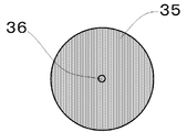
- FIG. 2 is a top view of the contact member 16 of FIG. 1, and the infiltration layer 35 forming the contact layer 18 and the recess 36 located at the center thereof are circular.
- the contact layer 18 and the recess 36 may have a shape other than a circle such as an ellipse.
- the contact portion holding conductor 38 is formed continuously with the contact layer support portion 22, and has a function of flowing the current flowing through the contact layer 18 through the contact layer support portion 22 when energized.
- the contact holding conductor 38 is provided with a screw hole 37 at the end opposite to the contact layer 18 so that it can be easily connected to a current-carrying conductor connected to the outside of the vacuum valve.
- the infiltration layer 35 is composed of a mother phase mainly composed of copper (Cu) or silver (Ag) and a component mainly composed of a high melting point component having a melting point higher than the melting point of the mother phase.
- the holding conductor made of the same material as the parent phase is formed integrally with the infiltrated layer 35.
- the porous plate from which the infiltrated layer 35 is based is a plate-like porous member produced by pressure-molding particles mainly composed of a high melting point component, and is usually higher than the matrix material. Use a metal with a melting point.
- the porous plate 31 is placed on the upper part of the mold, and the infiltrant (pellet 34) serving as a base material is placed on the porous plate 31.
- the infiltrating material is infiltrated into the porous plate by heating above the melting point of the material, and at the same time, the contact portion holding conductor 38 is integrally formed with the infiltrating material flowing from the opening to the bottom of the mold.
- the shape shown in FIG. 1 is adjusted mainly by surface machining. That is, the infiltrant uses a metal having a lower melting point than that of the porous plate.
- FIG. 3 is a flowchart showing processes involved in infiltration in the manufacturing process of the contact member 16 for the vacuum valve.
- 4 to 11 are a cross-sectional view and a top view for explaining the steps of the flowchart of FIG.
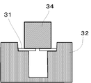
- FIG. 4 is a cross-sectional view in the step (step S1) of placing the porous plate 31 on the mold 32
- FIG. 5 is a top view thereof.
- step S 1 a porous plate 31 made of a pressure-molded porous body mainly composed of high melting point metal particles is placed on the shelf portion of the stepped mold 32.
- the diameter of the bottom of the mold 32 under the porous plate 31 is smaller than the diameter of the porous plate 31.
- a heat resistant material such as graphite may be used.
- a release material mainly composed of BN (boron nitride) may be applied to the inner wall of the mold 32.
- the pressure molding of the powder containing refractory metal particles as a main component may be performed, for example, by filling a normal press molding die and press molding at a predetermined pressure. Although it does not specifically limit as a pressure at the time of pressure molding, Preferably it is 50 Mpa or more and 200 Mpa or less.
- An opening 33 is provided at the center of the porous plate 31.
- the thickness of the porous plate 31 may be sufficiently thinner than the normal thickness of 5 to 15 mm that is pressure-molded when manufacturing the infiltration contact.
- the central opening 33 may be of a size that can flow to the lower part of the mold when the infiltrant is heated to the melting point or higher and melted, and the hole is opened to a size of about 2 mm to 10 mm.
- the surface of the porous plate 31 only needs to have a flat outer shape only on the side on which the infiltrant (pellet or the like) is placed, and the side in contact with the shelf of the mold 32 is not necessarily flat.
- the molded porous plate 31 is pre-sintered at a temperature not lower than the temperature used for infiltration in the subsequent steps and not higher than the melting point of the refractory metal.
- the pre-sintering temperature is in the range of 1083 ° C. or higher and 1860 ° C. or lower.
- a suitable atmosphere for the preliminary sintering is a non-oxidizing atmosphere such as a vacuum or a hydrogen atmosphere.
- the time required for the sintering may be a time that does not cause the sintered body to shrink greatly due to oversintering.
- FIG. 6 is a cross-sectional view in step S2 in which pellets 34 made of an infiltrant are placed on the mold 32
- FIG. 7 is a top view thereof.
- pellets 34 made of a metal material to be infiltrated are placed on the upper surface of the porous plate 31.
- the pellet 34 for example, a round bar or prismatic lump of Cu or Ag is used.
- the volume of the pellet 34 needs to be sufficiently larger than the volume of the porous plate 31, and is performed in a range of 2 to 100 times, for example.
- the porous plate 31 and the infiltrating material pellets 34 housed in the mold 32 are heated and melted in a range not lower than the melting point of the infiltrating material and not higher than the temperature of the preliminary sintering (step S3). Along with the dissolution, the liquefied pellet 34 is infiltrated into the porous plate 31 as an infiltrant (step S4).
- infiltration utilizes the action of liquefied metal, which is the infiltrant, permeating into the continuous voids in the porous body by capillary action.
- liquefied metal which is the infiltrant
- the surface tension gradually decreases and the fluidity tends to increase.
- it is preferable that the surface tension is large. Therefore, it is desirable to set the temperature during infiltration to a temperature close to the melting point. Specifically, a temperature range higher by about 10 ° C. to 100 ° C. than the melting point is preferable.
- FIG. 8 is a cross-sectional view showing a situation where the melted pellet 34m drops on the mold bottom.
- FIG. 9 is a top view corresponding to FIG.
- the porous plate 31 Floats on the upper surface side of the melted infiltrant (step S5).
- a high melting point metal used in the porous body of the porous plate 31 Cr (mean density 7.19g / cm 3), Ti ( 4.5g / cm 3), Ni (8.9g / cm 3), V ( 6.1g / cm 3), Fe ( 7.87g / cm 3), Co (8.9g / cm 3), consisted of one or two or more kinds of Mn (7.44g / cm 3) , the infiltrant metal Cu (8.96g / cm 3), when the Ag (10.5g / cm 3), the relationship is established.
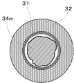
- FIG. 10 is a cross-sectional view showing a state in which the melted pellet 34m is accumulated at the bottom of the mold and fills the region under the infiltrated layer 35.
- FIG. FIG. 11 is a top view corresponding to FIG. In this state, the porous plate 31 slightly floats from the shelf portion of the mold 32.
- FIG. 12 is a cross-sectional view showing a state where the cooling is completed, and shows a state where the porous plate 31 floats up to the upper surface of the infiltrant and becomes the contact layer 35.
- the contact member is removed from the mold 32 (step S7), and the infiltration process is completed.
- the depth of the infiltrant remaining in the opening 33 at the center of the porous plate 31 is 0 in order to prevent the infiltrating material from coming into contact with the opposing contact point when it is incorporated into the vacuum valve.
- the recess 36 may be formed by scraping the infiltrant so as to be 5 mm or more. What is necessary is just to set the depth of the recessed part 36 suitably, and a part of infiltrant may be removed by methods other than cutting. Then, the contact member 16 as an integral molded product is completed by performing finishing processing of the contact surface and side surfaces, processing of forming a screw hole 37 in the bottom portion as shown in FIG.
- the contact member 16 of the present invention does not require a brazing step when assembling the vacuum valve, the brazing material does not diffuse to the contact side and the contact performance is not deteriorated.
- the thickness of the infiltrated layer 35 may be a dimension that exceeds the thickness that is actually consumed, and can be designed to the minimum necessary thickness, so that the resistance of the entire electrode can be reduced.
- it since it is supported by the contact layer support part 22, it can be provided with a strength that can withstand mechanical stress during finishing.
- FIG. FIG. 13 is a cross-sectional view showing a state in which the porous plate 31 and the small pellets 44 as the infiltrant and the bottom pellet 45 are arranged on the shelf of the mold 32.
- the second embodiment is different in that two pellets of a small pellet 44 and a bottom pellet 45 are used instead of the pellet 34. In the heating and melting step, these pellets are melted, and the small pellets 44 are liquefied and dripped from the opening 33 provided in the center of the porous plate 31, and dissolved as an infiltrant inside the porous plate 31. The point of soaking is the same. The molten small pellets 44 come into contact with the molten bottom pellet 45 to be integrated. Since the subsequent state is the same as that of the first embodiment, the description thereof is omitted.
- the volume of the infiltrating material dripping from the opening 33 can be reduced by using two pellets, the time required for infiltration can be shortened and productivity can be increased. Since the completed contact member 16 is the same as that of the first embodiment, the obtained effect is also common.
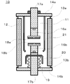
- FIG. 14 is a schematic cross-sectional view showing the structure of the vacuum valve 10 according to Embodiment 3 of the present invention.
- a stator side contact member 16a in which contacts and electrodes are integrated and a mover side contact member 16b are used as a pair, and these contact members are used in the first embodiment or the embodiment.
- the contact member described in the second embodiment is used.
- the envelope of the vacuum valve 10 is composed of an insulating container 12 formed in a cylindrical shape and metal lids 14a and 14b fixed to both ends of the insulating container 12 by sealing fittings 13a and 13b. Sealed in a high vacuum state of 1 ⁇ 10 ⁇ 3 Pa or higher.
- the metal lids 14a and 14b are respectively provided with cylindrical stator-side conductors 17a and mover-side conductors 17b so as to penetrate through the central portions thereof.
- the stator side contact member 16a and the mover side contact member 16b are fixed to the front end portions of the stator side conductor 17a and the mover side conductor 17b in the envelope by screw fastening, respectively.
- the total of the stator side conductor 17a and the stator side contact member 16a is called a stator side electrode.
- the whole of the mover side conductor 17b and the mover side contact member 16b is called a mover side electrode.
- a fixing method of the contact member a fitting structure that does not use brazing may be used.
- stator-side contact member 16a and the mover-side contact member 16b, and the stator-side contact layer 18a and the mover-side contact layer 18b, which are the respective contacts, are installed facing each other in parallel.
- a bellows 19 is attached to the mover side conductor 17b so that the mover side conductor 17b can be moved in the axial direction while keeping the inside of the vacuum valve 10 in a vacuum.
- FIG. 14 shows a state where the stator side contact member 16a and the mover side contact member 16b are open and open.
- stator side contact layer 18a and the mover side contact layer 18b come into contact with each other to be in a closed state, and the stator side conductor 17a and the mover side conductor 17b are brought into contact with each other. It becomes a conductive state.
- a metal bellows arc shield 20 is provided on the top of the bellows 19 in order to prevent the metal vapor from adhering to the bellows due to the arc generated between the contacts at the time of opening. Also, a metal insulating container arc shield 21 is provided so as to cover the gap between the stator-side contact member 16a and the mover-side contact member 16b in the opened state. The arc shield 21 for the insulating container is installed in order to prevent the inner wall surface of the insulating container 12 from being covered with the arc vapor, and is fixed to the metal lid 14a in the example of FIG. A region surrounded by the bellows arc shield 20 forms a blocking chamber 11.
- Example 1 The main component of the porous body was Cr, and Cu powder in an amount of 10 vol% of Cr was mixed in order to facilitate infiltration of Cu.
- the used Cr powder had an average particle size of 30 ⁇ m, and the mixed Cu powder had an average particle size of 30 ⁇ m.
- the porosity was 40% of the total volume of the porous body.
- the disk-shaped porous plate made of this porous body has a diameter of 30 mm and a thickness of 3 mm.
- the diameter (center hole diameter) of the opening at the center of the porous plate was 5 mm.
- a round bar having a height (thickness) of 40 mm formed from oxygen-free copper having a diameter of 25 mm was used as the pellet of the infiltrant.
- the casting mold used had a bottom diameter of 20 mm, a depth from the shelf to the bottom of 35 mm, and an inner diameter of the shelf of 32 mm.
- the height from the shelf to the upper edge of the mold is 20 mm.
- the release material BN powder was spray-coated inside the mold.
- the pre-sintering conditions for the porous body were a temperature of 1200 ° C. and a temperature holding time of 2 hours. Heating was performed with the infiltrant pellets placed on the porous plate, and infiltration was performed. The temperature during infiltration was 1100 ° C., slightly exceeding the melting point of Cu, 1083 ° C. The infiltration time was 3 hours and was carried out in a hydrogen atmosphere.
- Example 2 For Example 1, the same conditions were used except that the diameter of the opening of the porous plate was 8 mm.
- Example 3 For Example 1, the same conditions were used except that the thickness of the porous plate was 2 mm and the diameter of the central opening was 3 mm.
- Example 4 The same conditions were used for Example 1 except that the thickness of the porous plate was 4 mm and the diameter of the central opening was 5 mm.
- the porous plate was a disk having the same thickness and having no central opening. Otherwise, the same conditions as in Example 1 were used.
- Comparative Example 2 Unlike Example 1, infiltration was performed by placing pellets of the infiltrant under the porous plate. Otherwise, the same conditions as in Example 1 were used.
- Comparative Example 3 The porous body was infiltrated by a conventionally used technique. The thickness of the porous body is 10 mm, and the thickness of the infiltrant is 8 mm. As a porous plate, a disk without an opening was produced. A mold corresponding to the shape of the disk was used. Except for this, infiltration was performed using the same conditions as in Example 1. As will be described later, brazing was performed to form a contact member.
- the contacts from Example 1 to Example 4 were machined to have the shape shown in FIG.
- the portion that becomes the contact holding conductor portion was subjected only to polishing for smoothing the surface while maintaining the diameter of 20 mm after the infiltration, and processing for providing a screw hole for fastening on the side opposite to the contact layer was performed. Then, after being fastened with a conductor (rod) drawn to the outside of the vacuum valve via a metal lid and a screw, it was assembled into a vacuum valve.
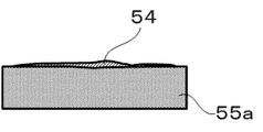
- FIG. 15 is a schematic diagram showing the state after infiltration of Comparative Example 3, and the infiltrant 54 remaining without being infiltrated is confirmed on the upper side of the infiltrated disk-like porous body 55a. Can do.
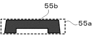
- FIG. 16 is a schematic cross-sectional view showing the shape of the porous body 55b after machining in Comparative Example 3, and the dotted line shows the outer shape of the porous body 55a after infiltration in FIG.
- FIG. 17 is a schematic cross-sectional view showing an electrode member produced using the processed porous body of FIG. 16, and a brazing material 56 is sandwiched between the porous body 55b and a round bar-shaped electrode portion 57 made of Cu. Then, brazing was done. Then, using two contact members of each of Examples 1 to 4 and Comparative Example 3, a vacuum valve having the form shown in FIG. 14 was assembled.
- a blocking test was performed by energizing between the electrodes.
- a power supply of AC 60 Hz and voltage 12 kV was used, and the interruption test was performed 10 times with the same interruption current, assuming that interruption was possible when the current became zero and that no re-ignition was made.
- the current started from 12 kA, and the interruption current value was increased by 4 kA up to 28 kA, and it was investigated how many times the interruption failed in 10 times.
- Table 2 is a list showing the results of the blocking test.
- the number of times of failure (NG) means the number of times of failing to cut off the current, and the number obtained by subtracting the number of failures from 10 is the number of times of success (OK).
- Comparative Example 3 had a failure to shut off at 20 kA, whereas Examples 1 to 4 were all successful 10 times, and the next 24 kA started to fail. At 28 kA, Comparative Example 3 failed 10 times out of 10 times, but in Example, the interruption was still successful, especially in Example 3 where the contact portion was thin, failure only occurred once, and the interruption performance was Overall improvement was confirmed. As can be confirmed from Table 1, this can be considered as an effect that the contact resistance is lowered because the high-resistance contact portion containing Cr in the entire electrode is thinned.
- the blocking performance has been improved.
- Example 5 In order to make the main component of the porous body WC and to facilitate infiltration of Cu, Cu powder in an amount of 30% of WC by volume ratio was mixed. The average particle size of the used WC powder is 9 ⁇ m, and the average particle size of the mixed Cu powder is 30 ⁇ m. The porosity was 35% of the total volume of the porous body.
- the disc-shaped porous plate made of this porous body has a diameter of 30 mm and a thickness of 4 mm. The diameter (center hole diameter) of the opening at the center of the porous plate was 5 mm.
- the preliminary sintering conditions for the porous body were a temperature of 1150 ° C. and a temperature holding time of 5 hours.
- the release material BN powder was spray-coated inside the mold.
- the casting mold used had a bottom diameter of 20 mm, a depth from the shelf to the bottom of 35 mm, and an inner diameter of the shelf of 32 mm.
- the height from the shelf to the upper edge of the mold is 20 mm.
- the infiltrated oxygen-free copper pellets having a diameter of 18 mm and a height of 35 mm were placed on the bottom of the mold, a porous plate was placed thereon, and a pellet having a diameter of 25 mm and a height of 8 mm was placed thereon.
- the temperature during infiltration was 1100 ° C., slightly exceeding the melting point of Cu, 1083 ° C.
- the infiltration time was 3 hours and was carried out in a hydrogen atmosphere.
- the contact material was taken out and machined to obtain the shape shown in FIG.
- the side surface was ground so that the diameter on the surface side was 28 mm, and the side surface of the contact support portion was tapered by about 80 ° with respect to the contact layer surface.
- the portion that becomes the contact holding conductor portion was subjected only to polishing for smoothing the surface while maintaining the diameter of 20 mm after the infiltration, and processing for providing a screw hole for fastening on the side opposite to the contact layer was performed.
- Example 4 After being fastened with a conductor (rod) drawn to the outside of the vacuum valve via a metal lid and a screw, it was assembled into a vacuum valve.
- the porous body was infiltrated by a conventionally used technique.
- the porous body has a diameter of 30 mm and a thickness of 8 mm, and the infiltrant has a thickness of 5 mm.
- As a porous plate a disk without an opening was produced. A mold corresponding to the shape of the disk was used. Except for this, infiltration was performed using the same conditions as in Example 5.
- the infiltrated porous body is machined to have a thickness of 3.5 mm, a surface diameter of 28 mm, and the side surface is ground to a surface side diameter of 28 mm.
- the taper was about 80 ° with respect to the layer surface.
- Comparative Example 4 failed 10 times out of 10, but in Example, the interruption was still successful and it was confirmed that the interruption performance was improved overall. This can be considered as an effect that the contact resistance is lowered because Example 5 does not have a brazing process.
- the contact resistance is lowered because Example 5 does not have a brazing process.
Landscapes
- Engineering & Computer Science (AREA)
- Mechanical Engineering (AREA)
- Manufacturing & Machinery (AREA)
- Chemical & Material Sciences (AREA)
- Composite Materials (AREA)
- Materials Engineering (AREA)
- High-Tension Arc-Extinguishing Switches Without Spraying Means (AREA)
- Manufacture Of Switches (AREA)
Abstract
L'invention concerne un élément de contact qui est pourvu d'une couche de contact comprenant un milieu poreux en forme de plaque contenant un métal à point de fusion élevé en tant que composant principal, dans lequel un agent d'infiltration contenant un métal à bas point de fusion en tant que composant principal est infiltré; une partie de support de couche de contact comprenant l'agent d'infiltration; et un conducteur de maintien de partie de contact. Le milieu poreux a une partie d'ouverture au niveau de la position qui est le centre de la couche de contact, et l'agent d'infiltration est formé en continu depuis l'intérieur de la partie d'ouverture jusqu'au conducteur de maintien de partie de contact.
Priority Applications (4)
| Application Number | Priority Date | Filing Date | Title |
|---|---|---|---|
| DE112017001814.5T DE112017001814B4 (de) | 2016-03-29 | 2017-01-20 | Kontaktelement, verfahren zur herstellung desselben und vakuum-schaltungsunterbrecher |
| JP2017532186A JP6304454B2 (ja) | 2016-03-29 | 2017-01-20 | 接点部材の製造方法および接点部材並びに真空バルブ |
| US16/078,088 US10629397B2 (en) | 2016-03-29 | 2017-01-20 | Contact member, method for producing the same, and vacuum interrupter |
| CN201780018997.5A CN108885958B (zh) | 2016-03-29 | 2017-01-20 | 触点构件的制造方法、触点构件以及真空阀 |
Applications Claiming Priority (2)
| Application Number | Priority Date | Filing Date | Title |
|---|---|---|---|
| JP2016066219 | 2016-03-29 | ||
| JP2016-066219 | 2016-03-29 |
Publications (1)
| Publication Number | Publication Date |
|---|---|
| WO2017168990A1 true WO2017168990A1 (fr) | 2017-10-05 |
Family
ID=59963015
Family Applications (1)
| Application Number | Title | Priority Date | Filing Date |
|---|---|---|---|
| PCT/JP2017/001910 WO2017168990A1 (fr) | 2016-03-29 | 2017-01-20 | Procédé de fabrication d'un élément de contact, élément de contact et soupape à vide |
Country Status (5)
| Country | Link |
|---|---|
| US (1) | US10629397B2 (fr) |
| JP (1) | JP6304454B2 (fr) |
| CN (1) | CN108885958B (fr) |
| DE (1) | DE112017001814B4 (fr) |
| WO (1) | WO2017168990A1 (fr) |
Cited By (1)
| Publication number | Priority date | Publication date | Assignee | Title |
|---|---|---|---|---|
| CN110289196A (zh) * | 2019-07-22 | 2019-09-27 | 旭格威科技(上海)有限公司 | 高可靠的直流接触器及应用于其的触头组件加工方法 |
Families Citing this family (2)
| Publication number | Priority date | Publication date | Assignee | Title |
|---|---|---|---|---|
| JP6323578B1 (ja) * | 2017-02-02 | 2018-05-16 | 株式会社明電舎 | 電極材料の製造方法及び電極材料 |
| JP6669327B1 (ja) * | 2019-08-27 | 2020-03-18 | 三菱電機株式会社 | 電気接点、電気接点を備えた真空バルブ |
Citations (5)
| Publication number | Priority date | Publication date | Assignee | Title |
|---|---|---|---|---|
| JPS5021670B1 (fr) * | 1970-12-24 | 1975-07-24 | ||
| JPS6396204A (ja) * | 1986-10-09 | 1988-04-27 | Toshiba Corp | 真空バルブ用接点材料の製造方法 |
| JPH08291305A (ja) * | 1995-04-21 | 1996-11-05 | Mitsubishi Electric Corp | 真空バルブ用電極材料の製造装置及び製造方法 |
| JP2005135778A (ja) * | 2003-10-31 | 2005-05-26 | Hitachi Ltd | 電気接点とその製造法及び真空バルブ用電極とそれを用いた真空バルブ並びに真空遮断器 |
| JP2010086898A (ja) * | 2008-10-02 | 2010-04-15 | Fuji Electric Fa Components & Systems Co Ltd | 真空バルブの接触子構造及びその製造方法 |
Family Cites Families (28)
| Publication number | Priority date | Publication date | Assignee | Title |
|---|---|---|---|---|
| GB1194674A (en) * | 1966-05-27 | 1970-06-10 | English Electric Co Ltd | Vacuum Type Electric Circuit Interrupting Devices |
| DE1558647B2 (de) * | 1967-08-05 | 1972-03-09 | Siemens Ag | Heterogenes durchdringungsverbundmetall als kontaktwerkstoff fuer vakuumschalter |
| JPS5021670A (fr) * | 1973-06-25 | 1975-03-07 | ||
| US4117288A (en) * | 1976-06-25 | 1978-09-26 | Westinghouse Electric Corp. | Vacuum type circuit interrupter with a contact having integral axial magnetic field means |
| US4190753A (en) * | 1978-04-13 | 1980-02-26 | Westinghouse Electric Corp. | High-density high-conductivity electrical contact material for vacuum interrupters and method of manufacture |
| US4501941A (en) * | 1982-10-26 | 1985-02-26 | Westinghouse Electric Corp. | Vacuum interrupter contact material |
| CA1236868A (fr) * | 1983-03-15 | 1988-05-17 | Yoshiyuki Kashiwagi | Interrupteur sous vide |
| CA1230909A (fr) * | 1983-03-22 | 1987-12-29 | Kaoru Kitakizaki | Electrode d'interrupteur a vide ayant une partie a faible conductivite pour la rotation magnetique de l'arc |
| JPS60128203A (ja) * | 1983-12-14 | 1985-07-09 | Toshiba Corp | 電気接点用複合焼結品 |
| JPH0760623B2 (ja) * | 1986-01-21 | 1995-06-28 | 株式会社東芝 | 真空バルブ用接点合金 |
| US4743718A (en) * | 1987-07-13 | 1988-05-10 | Westinghouse Electric Corp. | Electrical contacts for vacuum interrupter devices |
| JP2853308B2 (ja) * | 1990-09-20 | 1999-02-03 | 株式会社明電舎 | 電極材料の製造方法 |
| JP2943831B2 (ja) | 1992-12-03 | 1999-08-30 | ダイハツ工業株式会社 | 複合材料の製造方法 |
| JP3597544B2 (ja) * | 1993-02-05 | 2004-12-08 | 株式会社東芝 | 真空バルブ用接点材料及びその製造方法 |
| US5852266A (en) * | 1993-07-14 | 1998-12-22 | Hitachi, Ltd. | Vacuum circuit breaker as well as vacuum valve and electric contact used in same |
| JP2874522B2 (ja) * | 1993-07-14 | 1999-03-24 | 株式会社日立製作所 | 真空遮断器及びそれに用いる真空バルブと真空バルブ用電極並びにその製造法 |
| US5697150A (en) * | 1993-07-14 | 1997-12-16 | Hitachi, Ltd. | Method forming an electric contact in a vacuum circuit breaker |
| US5507336A (en) | 1995-01-17 | 1996-04-16 | The Procter & Gamble Company | Method of constructing fully dense metal molds and parts |
| JPH1012103A (ja) * | 1996-06-21 | 1998-01-16 | Hitachi Ltd | 真空遮断器及びそれに用いる真空バルブと電気接点 |
| JP3441331B2 (ja) * | 1997-03-07 | 2003-09-02 | 芝府エンジニアリング株式会社 | 真空バルブ用接点材料の製造方法 |
| GB2323213B (en) * | 1997-03-10 | 2001-10-17 | Gec Alsthom Ltd | Vacuum switching device |
| US8268234B2 (en) * | 1997-03-31 | 2012-09-18 | Lawrence Livermore National Security, Llc | Cermets from molten metal infiltration processing |
| JP4759987B2 (ja) * | 2004-11-15 | 2011-08-31 | 株式会社日立製作所 | 電極および電気接点とその製法 |
| JP2008021590A (ja) * | 2006-07-14 | 2008-01-31 | Hitachi Ltd | 真空バルブ用電気接点とその製法、真空バルブ用電極、真空バルブ及び真空遮断器 |
| CN102237204A (zh) * | 2010-04-27 | 2011-11-09 | 上海电科电工材料有限公司 | 一种钨基高压复合触头材料及其制造方法 |
| AT13963U1 (de) | 2012-06-01 | 2015-01-15 | Plansee Powertech Ag | Kontaktkomponente und Verfahren zu deren Herstellung |
| US9875869B2 (en) * | 2014-10-13 | 2018-01-23 | Eaton Corporation | Composite arc shields for vacuum interrupters and methods for forming same |
| CN105118702B (zh) * | 2015-07-17 | 2017-11-21 | 河南科技大学 | 铜合金材料用粉体组合物、复合材料层、电触头及其制备方法 |
-
2017
- 2017-01-20 JP JP2017532186A patent/JP6304454B2/ja active Active
- 2017-01-20 US US16/078,088 patent/US10629397B2/en active Active
- 2017-01-20 DE DE112017001814.5T patent/DE112017001814B4/de active Active
- 2017-01-20 CN CN201780018997.5A patent/CN108885958B/zh active Active
- 2017-01-20 WO PCT/JP2017/001910 patent/WO2017168990A1/fr active Application Filing
Patent Citations (5)
| Publication number | Priority date | Publication date | Assignee | Title |
|---|---|---|---|---|
| JPS5021670B1 (fr) * | 1970-12-24 | 1975-07-24 | ||
| JPS6396204A (ja) * | 1986-10-09 | 1988-04-27 | Toshiba Corp | 真空バルブ用接点材料の製造方法 |
| JPH08291305A (ja) * | 1995-04-21 | 1996-11-05 | Mitsubishi Electric Corp | 真空バルブ用電極材料の製造装置及び製造方法 |
| JP2005135778A (ja) * | 2003-10-31 | 2005-05-26 | Hitachi Ltd | 電気接点とその製造法及び真空バルブ用電極とそれを用いた真空バルブ並びに真空遮断器 |
| JP2010086898A (ja) * | 2008-10-02 | 2010-04-15 | Fuji Electric Fa Components & Systems Co Ltd | 真空バルブの接触子構造及びその製造方法 |
Cited By (1)
| Publication number | Priority date | Publication date | Assignee | Title |
|---|---|---|---|---|
| CN110289196A (zh) * | 2019-07-22 | 2019-09-27 | 旭格威科技(上海)有限公司 | 高可靠的直流接触器及应用于其的触头组件加工方法 |
Also Published As
| Publication number | Publication date |
|---|---|
| US20190051475A1 (en) | 2019-02-14 |
| DE112017001814T5 (de) | 2018-12-27 |
| CN108885958A (zh) | 2018-11-23 |
| DE112017001814B4 (de) | 2021-10-07 |
| CN108885958B (zh) | 2020-02-07 |
| US10629397B2 (en) | 2020-04-21 |
| JPWO2017168990A1 (ja) | 2018-04-05 |
| JP6304454B2 (ja) | 2018-04-04 |
Similar Documents
| Publication | Publication Date | Title |
|---|---|---|
| JP4979604B2 (ja) | 真空バルブ用電気接点 | |
| JP6304454B2 (ja) | 接点部材の製造方法および接点部材並びに真空バルブ | |
| JP4759987B2 (ja) | 電極および電気接点とその製法 | |
| WO2018142709A1 (fr) | Procédé de fabrication d'un matériau d'électrode et matériau d'électrode | |
| EP3062327A1 (fr) | Contact électrique pour soupape de dépression et son procédé de fabrication | |
| US9111670B2 (en) | Ceramic, graded resistivity monolith using the ceramic, and method of making | |
| JP6050994B2 (ja) | 電気接点、電気接点の製造方法、電極、真空バルブ、真空開閉機器 | |
| EP0155322A1 (fr) | Electrode de vis d'admission d'air | |
| JPH11232971A (ja) | 真空遮断器及びそれに用いる真空バルブと電気接点並びに製造方法 | |
| JP2009289652A (ja) | AgWC−Ag複合接点およびその製造方法 | |
| JP6669327B1 (ja) | 電気接点、電気接点を備えた真空バルブ | |
| US3548135A (en) | Contacts for vacuum interrupters | |
| JP5920408B2 (ja) | 電極材料の製造方法 | |
| KR19980087242A (ko) | 진공밸브의 모재의 제조방법 | |
| JP5211246B2 (ja) | 真空バルブ用電気接点及びその電気接点を用いた真空遮断器及び真空開閉機器 | |
| JP7062504B2 (ja) | 真空バルブ用接点材料および真空バルブ用接点材料の製造方法 | |
| KR910006114B1 (ko) | 진공인터럽터(interrupter)의 전극재료와 그의 제조방법 | |
| JP2016181476A (ja) | 真空バルブ用接点および真空バルブ用接点の製造方法、並びに真空バルブ | |
| JP2006228454A (ja) | 真空バルブ用電極及びその製造方法 | |
| JP2004332046A (ja) | 遮断器用接点材料及び真空遮断器 | |
| JP2017036479A (ja) | 電極材料及び電極材料の製造方法 | |
| WO2010095163A1 (fr) | Contact électrique pour vanne à vide et disjoncteur à vide l'utilisant | |
| JPH11167847A (ja) | 真空遮断器及びそれに用いる真空バルブとその電極 | |
| JP2001243857A (ja) | 真空バルブ | |
| JPH04141924A (ja) | 電極材料の製造方法 |
Legal Events
| Date | Code | Title | Description |
|---|---|---|---|
| ENP | Entry into the national phase |
Ref document number: 2017532186 Country of ref document: JP Kind code of ref document: A |
|
| 121 | Ep: the epo has been informed by wipo that ep was designated in this application |
Ref document number: 17773540 Country of ref document: EP Kind code of ref document: A1 |
|
| 122 | Ep: pct application non-entry in european phase |
Ref document number: 17773540 Country of ref document: EP Kind code of ref document: A1 |