WO2017168990A1 - Method for manufacturing contact member, contact member, and vacuum valve - Google Patents
Method for manufacturing contact member, contact member, and vacuum valve Download PDFInfo
- Publication number
- WO2017168990A1 WO2017168990A1 PCT/JP2017/001910 JP2017001910W WO2017168990A1 WO 2017168990 A1 WO2017168990 A1 WO 2017168990A1 JP 2017001910 W JP2017001910 W JP 2017001910W WO 2017168990 A1 WO2017168990 A1 WO 2017168990A1
- Authority
- WO
- WIPO (PCT)
- Prior art keywords
- infiltrant
- contact
- contact member
- porous plate
- porous body
- Prior art date
Links
Images


Classifications
-
- H—ELECTRICITY
- H01—ELECTRIC ELEMENTS
- H01H—ELECTRIC SWITCHES; RELAYS; SELECTORS; EMERGENCY PROTECTIVE DEVICES
- H01H33/00—High-tension or heavy-current switches with arc-extinguishing or arc-preventing means
- H01H33/60—Switches wherein the means for extinguishing or preventing the arc do not include separate means for obtaining or increasing flow of arc-extinguishing fluid
- H01H33/66—Vacuum switches
- H01H33/664—Contacts; Arc-extinguishing means, e.g. arcing rings
-
- B—PERFORMING OPERATIONS; TRANSPORTING
- B22—CASTING; POWDER METALLURGY
- B22D—CASTING OF METALS; CASTING OF OTHER SUBSTANCES BY THE SAME PROCESSES OR DEVICES
- B22D19/00—Casting in, on, or around objects which form part of the product
-
- B—PERFORMING OPERATIONS; TRANSPORTING
- B22—CASTING; POWDER METALLURGY
- B22F—WORKING METALLIC POWDER; MANUFACTURE OF ARTICLES FROM METALLIC POWDER; MAKING METALLIC POWDER; APPARATUS OR DEVICES SPECIALLY ADAPTED FOR METALLIC POWDER
- B22F3/00—Manufacture of workpieces or articles from metallic powder characterised by the manner of compacting or sintering; Apparatus specially adapted therefor ; Presses and furnaces
- B22F3/24—After-treatment of workpieces or articles
- B22F3/26—Impregnating
-
- B—PERFORMING OPERATIONS; TRANSPORTING
- B22—CASTING; POWDER METALLURGY
- B22F—WORKING METALLIC POWDER; MANUFACTURE OF ARTICLES FROM METALLIC POWDER; MAKING METALLIC POWDER; APPARATUS OR DEVICES SPECIALLY ADAPTED FOR METALLIC POWDER
- B22F7/00—Manufacture of composite layers, workpieces, or articles, comprising metallic powder, by sintering the powder, with or without compacting wherein at least one part is obtained by sintering or compression
- B22F7/02—Manufacture of composite layers, workpieces, or articles, comprising metallic powder, by sintering the powder, with or without compacting wherein at least one part is obtained by sintering or compression of composite layers
- B22F7/04—Manufacture of composite layers, workpieces, or articles, comprising metallic powder, by sintering the powder, with or without compacting wherein at least one part is obtained by sintering or compression of composite layers with one or more layers not made from powder, e.g. made from solid metal
-
- H—ELECTRICITY
- H01—ELECTRIC ELEMENTS
- H01H—ELECTRIC SWITCHES; RELAYS; SELECTORS; EMERGENCY PROTECTIVE DEVICES
- H01H1/00—Contacts
- H01H1/02—Contacts characterised by the material thereof
- H01H1/0203—Contacts characterised by the material thereof specially adapted for vacuum switches
- H01H1/0206—Contacts characterised by the material thereof specially adapted for vacuum switches containing as major components Cu and Cr
-
- H—ELECTRICITY
- H01—ELECTRIC ELEMENTS
- H01H—ELECTRIC SWITCHES; RELAYS; SELECTORS; EMERGENCY PROTECTIVE DEVICES
- H01H11/00—Apparatus or processes specially adapted for the manufacture of electric switches
- H01H11/04—Apparatus or processes specially adapted for the manufacture of electric switches of switch contacts
- H01H11/048—Apparatus or processes specially adapted for the manufacture of electric switches of switch contacts by powder-metallurgical processes
-
- H—ELECTRICITY
- H01—ELECTRIC ELEMENTS
- H01H—ELECTRIC SWITCHES; RELAYS; SELECTORS; EMERGENCY PROTECTIVE DEVICES
- H01H33/00—High-tension or heavy-current switches with arc-extinguishing or arc-preventing means
- H01H33/60—Switches wherein the means for extinguishing or preventing the arc do not include separate means for obtaining or increasing flow of arc-extinguishing fluid
- H01H33/66—Vacuum switches
- H01H33/662—Housings or protective screens
Definitions
- the present invention relates to a vacuum valve applied to a current interrupting vacuum circuit breaker used in a power transmission system, a contact member used in the vacuum valve, and a method of manufacturing the contact member.
- the vacuum valve has a structure in which a fixed electrode and a movable electrode are disposed opposite to each other in a coaxial position inside an insulating container maintained at a high vacuum. During energization, the fixed electrode and the movable electrode are in contact with each other, and when an overload current or a short-circuit current occurs, the current can be cut off by instantaneously opening these electrodes.
- the contact material used for the contact portion between the fixed electrode and the movable electrode of such a vacuum valve is mainly required to have a breaking performance and a withstand voltage performance at the time of opening. Since these performances required for the contact material are mutually contradictory properties, it is difficult to manufacture the contact material using a material composed of a single element. Therefore, the conventional contact material is manufactured using the material which combined 2 or more types of elements.
- a contact material such as a Cu—W contact or a Cu—Cr contact using a highly conductive material such as copper (Cu), tungsten (W) or chromium (Cr) is generally used as the withstand voltage material.
- a contact material of a vacuum valve that requires low surge characteristics tungsten carbide (WC), which is an electron emission component, is generally replaced with copper (Cu), silver (Ag), which is a highly conductive material.
- Cu-WC-based and Ag-WC-based contact materials dispersed in (1) are used.
- the following infiltration method is used as a method for manufacturing these contact materials.
- brazing After contact processing, it is brazed to a copper rod that becomes a conductor when energized, but if the ratio of the withstand voltage material component that is inferior in wettability with the brazing material is large on the contact surface, brazing becomes incomplete and the contact May fall off, or the contact area between the copper bar and the contact may be reduced.
- the brazing process when assembling the vacuum valve is indispensable.
- the brazing material diffuses to the contact portion side to deteriorate the contact performance, or the resistance value increases depending on the kind of the brazing material.
- the thickness of the contact part needs to be increased during finishing machining, it must be made with a thickness that is excessive compared to the thickness that is actually consumed, and the overall resistance of the electrode is low.
- the present invention has been made to solve the above-described problems, and obtains a contact member for a vacuum valve that integrally molds the contact portion and the contact portion holding conductor without requiring brazing of the contact portion. For the purpose.
- the method for producing a contact member according to the present invention comprises a step of disposing a porous plate made of a porous material mainly composed of a refractory metal and having an opening in the center in a mold, and a lower side above the porous plate.
- a step of disposing an infiltrant mainly composed of a melting point metal, a step of heating and melting the infiltrant, a step of passing a part of the infiltrant that has melted the opening, and a molten infiltrant A step of levitating the porous plate on the upper surface side and a step of cooling and solidifying the infiltrant.
- the contact member of the present invention comprises a contact layer made of a plate-like porous body mainly composed of a high melting point metal, infiltrated with an infiltrant composed mainly of a low melting point metal, and an infiltrant.
- the porous body has an opening at a position that becomes the center of the contact layer, and the infiltrant continues from the opening to the contact holding conductor.
- the contact portion refers to a contact layer and a contact layer support portion.
- a contact member having a low resistance and high reliability can be obtained by integrally molding the contact portion and the contact portion holding conductor.
- FIG. 3 is a cross-sectional view of a contact member for a vacuum valve showing Embodiment 1.
- FIG. 3 is a top view of a contact member for a vacuum valve showing Embodiment 1.
- FIG. 3 is a flowchart showing a process related to infiltration of a contact member for a vacuum valve in the first embodiment.
- FIG. 3 is a cross-sectional view showing a step of arranging a porous plate on a mold in the first embodiment.
- FIG. 3 is a top view showing a step of arranging a porous plate on a mold in the first embodiment.
- FIG. 4 is a cross-sectional view showing a step of arranging pellets made of an infiltrant on mold 32 in the first embodiment.
- FIG. 6 is a top view showing a step of arranging pellets 34 made of an infiltrant on mold 32 in the first embodiment.
- FIG. 3 is a cross-sectional view showing a situation where dissolved pellets drip on the mold bottom in the first embodiment.
- FIG. 3 is a top view of the first embodiment in a state where dissolved pellets drip on the mold bottom.
- FIG. 3 is a cross-sectional view showing a state in which melted pellets fill a region under a porous plate in a mold in the first embodiment.
- FIG. 3 is a top view in a state where the melted pellets fill a region under a porous plate in a mold in the first embodiment.
- FIG. 3 is a top view in a state where the melted pellets fill a region under a porous plate in a mold in the first embodiment.
- FIG. 3 is a cross-sectional view showing a state where cooling of the contact member is completed in the first embodiment.
- FIG. 6 is a cross-sectional view showing a state in which a porous plate, small pellets, and a bottom pellet are arranged in a mold in the second embodiment. 6 is a schematic cross-sectional view showing the structure of a vacuum valve according to Embodiment 3.
- FIG. 10 is a schematic diagram showing a state after infiltration of Comparative Example 3.
- FIG. It is a cross-sectional schematic diagram which shows the shape of the porous body after performing the machining of the comparative example 3. It is a cross-sectional schematic diagram which shows the conductor produced using the processed porous body of the comparative example 3.
- FIG. 1 is a cross-sectional view of a contact member 16 for a vacuum valve according to Embodiment 1 of the present invention.
- the contact layer 18 is a surface obtained by grinding or machining the surface of the infiltrated layer 35 that is a porous body that has been infiltrated, and usually has a flat surface.
- the contact layer support portion 22 is in contact with the infiltrated layer 35 and is a portion that supports the infiltrated layer 35.
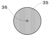
- FIG. 2 is a top view of the contact member 16 of FIG. 1, and the infiltration layer 35 forming the contact layer 18 and the recess 36 located at the center thereof are circular.
- the contact layer 18 and the recess 36 may have a shape other than a circle such as an ellipse.
- the contact portion holding conductor 38 is formed continuously with the contact layer support portion 22, and has a function of flowing the current flowing through the contact layer 18 through the contact layer support portion 22 when energized.
- the contact holding conductor 38 is provided with a screw hole 37 at the end opposite to the contact layer 18 so that it can be easily connected to a current-carrying conductor connected to the outside of the vacuum valve.
- the infiltration layer 35 is composed of a mother phase mainly composed of copper (Cu) or silver (Ag) and a component mainly composed of a high melting point component having a melting point higher than the melting point of the mother phase.
- the holding conductor made of the same material as the parent phase is formed integrally with the infiltrated layer 35.
- the porous plate from which the infiltrated layer 35 is based is a plate-like porous member produced by pressure-molding particles mainly composed of a high melting point component, and is usually higher than the matrix material. Use a metal with a melting point.
- the porous plate 31 is placed on the upper part of the mold, and the infiltrant (pellet 34) serving as a base material is placed on the porous plate 31.
- the infiltrating material is infiltrated into the porous plate by heating above the melting point of the material, and at the same time, the contact portion holding conductor 38 is integrally formed with the infiltrating material flowing from the opening to the bottom of the mold.
- the shape shown in FIG. 1 is adjusted mainly by surface machining. That is, the infiltrant uses a metal having a lower melting point than that of the porous plate.
- FIG. 3 is a flowchart showing processes involved in infiltration in the manufacturing process of the contact member 16 for the vacuum valve.
- 4 to 11 are a cross-sectional view and a top view for explaining the steps of the flowchart of FIG.
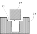
- FIG. 4 is a cross-sectional view in the step (step S1) of placing the porous plate 31 on the mold 32
- FIG. 5 is a top view thereof.
- step S 1 a porous plate 31 made of a pressure-molded porous body mainly composed of high melting point metal particles is placed on the shelf portion of the stepped mold 32.
- the diameter of the bottom of the mold 32 under the porous plate 31 is smaller than the diameter of the porous plate 31.
- a heat resistant material such as graphite may be used.
- a release material mainly composed of BN (boron nitride) may be applied to the inner wall of the mold 32.
- the pressure molding of the powder containing refractory metal particles as a main component may be performed, for example, by filling a normal press molding die and press molding at a predetermined pressure. Although it does not specifically limit as a pressure at the time of pressure molding, Preferably it is 50 Mpa or more and 200 Mpa or less.
- An opening 33 is provided at the center of the porous plate 31.
- the thickness of the porous plate 31 may be sufficiently thinner than the normal thickness of 5 to 15 mm that is pressure-molded when manufacturing the infiltration contact.
- the central opening 33 may be of a size that can flow to the lower part of the mold when the infiltrant is heated to the melting point or higher and melted, and the hole is opened to a size of about 2 mm to 10 mm.
- the surface of the porous plate 31 only needs to have a flat outer shape only on the side on which the infiltrant (pellet or the like) is placed, and the side in contact with the shelf of the mold 32 is not necessarily flat.
- the molded porous plate 31 is pre-sintered at a temperature not lower than the temperature used for infiltration in the subsequent steps and not higher than the melting point of the refractory metal.
- the pre-sintering temperature is in the range of 1083 ° C. or higher and 1860 ° C. or lower.
- a suitable atmosphere for the preliminary sintering is a non-oxidizing atmosphere such as a vacuum or a hydrogen atmosphere.
- the time required for the sintering may be a time that does not cause the sintered body to shrink greatly due to oversintering.
- FIG. 6 is a cross-sectional view in step S2 in which pellets 34 made of an infiltrant are placed on the mold 32
- FIG. 7 is a top view thereof.
- pellets 34 made of a metal material to be infiltrated are placed on the upper surface of the porous plate 31.
- the pellet 34 for example, a round bar or prismatic lump of Cu or Ag is used.
- the volume of the pellet 34 needs to be sufficiently larger than the volume of the porous plate 31, and is performed in a range of 2 to 100 times, for example.
- the porous plate 31 and the infiltrating material pellets 34 housed in the mold 32 are heated and melted in a range not lower than the melting point of the infiltrating material and not higher than the temperature of the preliminary sintering (step S3). Along with the dissolution, the liquefied pellet 34 is infiltrated into the porous plate 31 as an infiltrant (step S4).
- infiltration utilizes the action of liquefied metal, which is the infiltrant, permeating into the continuous voids in the porous body by capillary action.
- liquefied metal which is the infiltrant
- the surface tension gradually decreases and the fluidity tends to increase.
- it is preferable that the surface tension is large. Therefore, it is desirable to set the temperature during infiltration to a temperature close to the melting point. Specifically, a temperature range higher by about 10 ° C. to 100 ° C. than the melting point is preferable.
- FIG. 8 is a cross-sectional view showing a situation where the melted pellet 34m drops on the mold bottom.
- FIG. 9 is a top view corresponding to FIG.
- the porous plate 31 Floats on the upper surface side of the melted infiltrant (step S5).
- a high melting point metal used in the porous body of the porous plate 31 Cr (mean density 7.19g / cm 3), Ti ( 4.5g / cm 3), Ni (8.9g / cm 3), V ( 6.1g / cm 3), Fe ( 7.87g / cm 3), Co (8.9g / cm 3), consisted of one or two or more kinds of Mn (7.44g / cm 3) , the infiltrant metal Cu (8.96g / cm 3), when the Ag (10.5g / cm 3), the relationship is established.
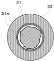
- FIG. 10 is a cross-sectional view showing a state in which the melted pellet 34m is accumulated at the bottom of the mold and fills the region under the infiltrated layer 35.
- FIG. FIG. 11 is a top view corresponding to FIG. In this state, the porous plate 31 slightly floats from the shelf portion of the mold 32.
- FIG. 12 is a cross-sectional view showing a state where the cooling is completed, and shows a state where the porous plate 31 floats up to the upper surface of the infiltrant and becomes the contact layer 35.
- the contact member is removed from the mold 32 (step S7), and the infiltration process is completed.
- the depth of the infiltrant remaining in the opening 33 at the center of the porous plate 31 is 0 in order to prevent the infiltrating material from coming into contact with the opposing contact point when it is incorporated into the vacuum valve.
- the recess 36 may be formed by scraping the infiltrant so as to be 5 mm or more. What is necessary is just to set the depth of the recessed part 36 suitably, and a part of infiltrant may be removed by methods other than cutting. Then, the contact member 16 as an integral molded product is completed by performing finishing processing of the contact surface and side surfaces, processing of forming a screw hole 37 in the bottom portion as shown in FIG.
- the contact member 16 of the present invention does not require a brazing step when assembling the vacuum valve, the brazing material does not diffuse to the contact side and the contact performance is not deteriorated.
- the thickness of the infiltrated layer 35 may be a dimension that exceeds the thickness that is actually consumed, and can be designed to the minimum necessary thickness, so that the resistance of the entire electrode can be reduced.
- it since it is supported by the contact layer support part 22, it can be provided with a strength that can withstand mechanical stress during finishing.
- FIG. FIG. 13 is a cross-sectional view showing a state in which the porous plate 31 and the small pellets 44 as the infiltrant and the bottom pellet 45 are arranged on the shelf of the mold 32.
- the second embodiment is different in that two pellets of a small pellet 44 and a bottom pellet 45 are used instead of the pellet 34. In the heating and melting step, these pellets are melted, and the small pellets 44 are liquefied and dripped from the opening 33 provided in the center of the porous plate 31, and dissolved as an infiltrant inside the porous plate 31. The point of soaking is the same. The molten small pellets 44 come into contact with the molten bottom pellet 45 to be integrated. Since the subsequent state is the same as that of the first embodiment, the description thereof is omitted.
- the volume of the infiltrating material dripping from the opening 33 can be reduced by using two pellets, the time required for infiltration can be shortened and productivity can be increased. Since the completed contact member 16 is the same as that of the first embodiment, the obtained effect is also common.
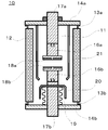
- FIG. 14 is a schematic cross-sectional view showing the structure of the vacuum valve 10 according to Embodiment 3 of the present invention.
- a stator side contact member 16a in which contacts and electrodes are integrated and a mover side contact member 16b are used as a pair, and these contact members are used in the first embodiment or the embodiment.
- the contact member described in the second embodiment is used.
- the envelope of the vacuum valve 10 is composed of an insulating container 12 formed in a cylindrical shape and metal lids 14a and 14b fixed to both ends of the insulating container 12 by sealing fittings 13a and 13b. Sealed in a high vacuum state of 1 ⁇ 10 ⁇ 3 Pa or higher.
- the metal lids 14a and 14b are respectively provided with cylindrical stator-side conductors 17a and mover-side conductors 17b so as to penetrate through the central portions thereof.
- the stator side contact member 16a and the mover side contact member 16b are fixed to the front end portions of the stator side conductor 17a and the mover side conductor 17b in the envelope by screw fastening, respectively.
- the total of the stator side conductor 17a and the stator side contact member 16a is called a stator side electrode.
- the whole of the mover side conductor 17b and the mover side contact member 16b is called a mover side electrode.
- a fixing method of the contact member a fitting structure that does not use brazing may be used.
- stator-side contact member 16a and the mover-side contact member 16b, and the stator-side contact layer 18a and the mover-side contact layer 18b, which are the respective contacts, are installed facing each other in parallel.
- a bellows 19 is attached to the mover side conductor 17b so that the mover side conductor 17b can be moved in the axial direction while keeping the inside of the vacuum valve 10 in a vacuum.
- FIG. 14 shows a state where the stator side contact member 16a and the mover side contact member 16b are open and open.
- stator side contact layer 18a and the mover side contact layer 18b come into contact with each other to be in a closed state, and the stator side conductor 17a and the mover side conductor 17b are brought into contact with each other. It becomes a conductive state.
- a metal bellows arc shield 20 is provided on the top of the bellows 19 in order to prevent the metal vapor from adhering to the bellows due to the arc generated between the contacts at the time of opening. Also, a metal insulating container arc shield 21 is provided so as to cover the gap between the stator-side contact member 16a and the mover-side contact member 16b in the opened state. The arc shield 21 for the insulating container is installed in order to prevent the inner wall surface of the insulating container 12 from being covered with the arc vapor, and is fixed to the metal lid 14a in the example of FIG. A region surrounded by the bellows arc shield 20 forms a blocking chamber 11.
- Example 1 The main component of the porous body was Cr, and Cu powder in an amount of 10 vol% of Cr was mixed in order to facilitate infiltration of Cu.
- the used Cr powder had an average particle size of 30 ⁇ m, and the mixed Cu powder had an average particle size of 30 ⁇ m.
- the porosity was 40% of the total volume of the porous body.
- the disk-shaped porous plate made of this porous body has a diameter of 30 mm and a thickness of 3 mm.
- the diameter (center hole diameter) of the opening at the center of the porous plate was 5 mm.
- a round bar having a height (thickness) of 40 mm formed from oxygen-free copper having a diameter of 25 mm was used as the pellet of the infiltrant.
- the casting mold used had a bottom diameter of 20 mm, a depth from the shelf to the bottom of 35 mm, and an inner diameter of the shelf of 32 mm.
- the height from the shelf to the upper edge of the mold is 20 mm.
- the release material BN powder was spray-coated inside the mold.
- the pre-sintering conditions for the porous body were a temperature of 1200 ° C. and a temperature holding time of 2 hours. Heating was performed with the infiltrant pellets placed on the porous plate, and infiltration was performed. The temperature during infiltration was 1100 ° C., slightly exceeding the melting point of Cu, 1083 ° C. The infiltration time was 3 hours and was carried out in a hydrogen atmosphere.
- Example 2 For Example 1, the same conditions were used except that the diameter of the opening of the porous plate was 8 mm.
- Example 3 For Example 1, the same conditions were used except that the thickness of the porous plate was 2 mm and the diameter of the central opening was 3 mm.
- Example 4 The same conditions were used for Example 1 except that the thickness of the porous plate was 4 mm and the diameter of the central opening was 5 mm.
- the porous plate was a disk having the same thickness and having no central opening. Otherwise, the same conditions as in Example 1 were used.
- Comparative Example 2 Unlike Example 1, infiltration was performed by placing pellets of the infiltrant under the porous plate. Otherwise, the same conditions as in Example 1 were used.
- Comparative Example 3 The porous body was infiltrated by a conventionally used technique. The thickness of the porous body is 10 mm, and the thickness of the infiltrant is 8 mm. As a porous plate, a disk without an opening was produced. A mold corresponding to the shape of the disk was used. Except for this, infiltration was performed using the same conditions as in Example 1. As will be described later, brazing was performed to form a contact member.
- the contacts from Example 1 to Example 4 were machined to have the shape shown in FIG.
- the portion that becomes the contact holding conductor portion was subjected only to polishing for smoothing the surface while maintaining the diameter of 20 mm after the infiltration, and processing for providing a screw hole for fastening on the side opposite to the contact layer was performed. Then, after being fastened with a conductor (rod) drawn to the outside of the vacuum valve via a metal lid and a screw, it was assembled into a vacuum valve.
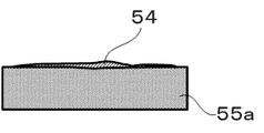
- FIG. 15 is a schematic diagram showing the state after infiltration of Comparative Example 3, and the infiltrant 54 remaining without being infiltrated is confirmed on the upper side of the infiltrated disk-like porous body 55a. Can do.
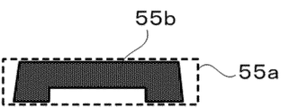
- FIG. 16 is a schematic cross-sectional view showing the shape of the porous body 55b after machining in Comparative Example 3, and the dotted line shows the outer shape of the porous body 55a after infiltration in FIG.
- FIG. 17 is a schematic cross-sectional view showing an electrode member produced using the processed porous body of FIG. 16, and a brazing material 56 is sandwiched between the porous body 55b and a round bar-shaped electrode portion 57 made of Cu. Then, brazing was done. Then, using two contact members of each of Examples 1 to 4 and Comparative Example 3, a vacuum valve having the form shown in FIG. 14 was assembled.
- a blocking test was performed by energizing between the electrodes.
- a power supply of AC 60 Hz and voltage 12 kV was used, and the interruption test was performed 10 times with the same interruption current, assuming that interruption was possible when the current became zero and that no re-ignition was made.
- the current started from 12 kA, and the interruption current value was increased by 4 kA up to 28 kA, and it was investigated how many times the interruption failed in 10 times.
- Table 2 is a list showing the results of the blocking test.
- the number of times of failure (NG) means the number of times of failing to cut off the current, and the number obtained by subtracting the number of failures from 10 is the number of times of success (OK).
- Comparative Example 3 had a failure to shut off at 20 kA, whereas Examples 1 to 4 were all successful 10 times, and the next 24 kA started to fail. At 28 kA, Comparative Example 3 failed 10 times out of 10 times, but in Example, the interruption was still successful, especially in Example 3 where the contact portion was thin, failure only occurred once, and the interruption performance was Overall improvement was confirmed. As can be confirmed from Table 1, this can be considered as an effect that the contact resistance is lowered because the high-resistance contact portion containing Cr in the entire electrode is thinned.
- the blocking performance has been improved.
- Example 5 In order to make the main component of the porous body WC and to facilitate infiltration of Cu, Cu powder in an amount of 30% of WC by volume ratio was mixed. The average particle size of the used WC powder is 9 ⁇ m, and the average particle size of the mixed Cu powder is 30 ⁇ m. The porosity was 35% of the total volume of the porous body.
- the disc-shaped porous plate made of this porous body has a diameter of 30 mm and a thickness of 4 mm. The diameter (center hole diameter) of the opening at the center of the porous plate was 5 mm.
- the preliminary sintering conditions for the porous body were a temperature of 1150 ° C. and a temperature holding time of 5 hours.
- the release material BN powder was spray-coated inside the mold.
- the casting mold used had a bottom diameter of 20 mm, a depth from the shelf to the bottom of 35 mm, and an inner diameter of the shelf of 32 mm.
- the height from the shelf to the upper edge of the mold is 20 mm.
- the infiltrated oxygen-free copper pellets having a diameter of 18 mm and a height of 35 mm were placed on the bottom of the mold, a porous plate was placed thereon, and a pellet having a diameter of 25 mm and a height of 8 mm was placed thereon.
- the temperature during infiltration was 1100 ° C., slightly exceeding the melting point of Cu, 1083 ° C.
- the infiltration time was 3 hours and was carried out in a hydrogen atmosphere.
- the contact material was taken out and machined to obtain the shape shown in FIG.
- the side surface was ground so that the diameter on the surface side was 28 mm, and the side surface of the contact support portion was tapered by about 80 ° with respect to the contact layer surface.
- the portion that becomes the contact holding conductor portion was subjected only to polishing for smoothing the surface while maintaining the diameter of 20 mm after the infiltration, and processing for providing a screw hole for fastening on the side opposite to the contact layer was performed.
- Example 4 After being fastened with a conductor (rod) drawn to the outside of the vacuum valve via a metal lid and a screw, it was assembled into a vacuum valve.
- the porous body was infiltrated by a conventionally used technique.
- the porous body has a diameter of 30 mm and a thickness of 8 mm, and the infiltrant has a thickness of 5 mm.
- As a porous plate a disk without an opening was produced. A mold corresponding to the shape of the disk was used. Except for this, infiltration was performed using the same conditions as in Example 5.
- the infiltrated porous body is machined to have a thickness of 3.5 mm, a surface diameter of 28 mm, and the side surface is ground to a surface side diameter of 28 mm.
- the taper was about 80 ° with respect to the layer surface.
- Comparative Example 4 failed 10 times out of 10, but in Example, the interruption was still successful and it was confirmed that the interruption performance was improved overall. This can be considered as an effect that the contact resistance is lowered because Example 5 does not have a brazing process.
- the contact resistance is lowered because Example 5 does not have a brazing process.
Abstract
This contact member is provided with a contact layer comprising a plate-shaped porous medium having a high-melting metal as a main component, into which an infiltrant having a low-melting metal as a main component has infiltrated; a contact layer support part comprising the infiltrant; and a contact-part-holding conductor. The porous medium has an opening part at the position which is the center of the contact layer, and the infiltrant is formed continuously from inside the opening part up to the contact-part-holding conductor.
Description
本発明は、送電系統などで用いられる電流遮断用の真空遮断器に適用される真空バルブと、真空バルブに用いられる接点部材および接点部材の製造方法に関する。
The present invention relates to a vacuum valve applied to a current interrupting vacuum circuit breaker used in a power transmission system, a contact member used in the vacuum valve, and a method of manufacturing the contact member.
真空バルブは、高真空に保たれた絶縁容器の内部に、固定電極と可動電極とが同軸の位置に対向配置された構造を有している。通電時には、固定電極と可動電極とが接触しており、過負荷電流または短絡電流が発生した際に、これらの電極が瞬時に開極されることで電流を遮断することができる。
The vacuum valve has a structure in which a fixed electrode and a movable electrode are disposed opposite to each other in a coaxial position inside an insulating container maintained at a high vacuum. During energization, the fixed electrode and the movable electrode are in contact with each other, and when an overload current or a short-circuit current occurs, the current can be cut off by instantaneously opening these electrodes.
このような真空バルブの固定電極と可動電極との接触部に使用される接点材料には、主に遮断性能と開極時の耐電圧性能が要求される。接点材料に要求されるこれらの性能は、互いに相反する性質であるため、接点材料を単一の元素からなる材料を用いて製造することは困難である。そのため、従来の接点材料は、二種以上の元素を組み合わせた材料を用いて製造されている。
The contact material used for the contact portion between the fixed electrode and the movable electrode of such a vacuum valve is mainly required to have a breaking performance and a withstand voltage performance at the time of opening. Since these performances required for the contact material are mutually contradictory properties, it is difficult to manufacture the contact material using a material composed of a single element. Therefore, the conventional contact material is manufactured using the material which combined 2 or more types of elements.
例えば、耐電圧材料には、高導電材料の銅(Cu)とタングステン(W)やクロム(Cr)を用いた、Cu-W接点やCu-Cr接点などの接点材料が一般に用いられている。あるいは、低サージ性が要求される真空バルブの接点材料には、電流遮断時間を延ばすため、一般に、電子放出成分であるタングステンカーバイド(WC)を、高導電材料の銅(Cu)、銀(Ag)に分散させたCu-WC系、Ag-WC系の接点材料が用いられている。
For example, a contact material such as a Cu—W contact or a Cu—Cr contact using a highly conductive material such as copper (Cu), tungsten (W) or chromium (Cr) is generally used as the withstand voltage material. Alternatively, in order to extend the current interruption time for a contact material of a vacuum valve that requires low surge characteristics, tungsten carbide (WC), which is an electron emission component, is generally replaced with copper (Cu), silver (Ag), which is a highly conductive material. Cu-WC-based and Ag-WC-based contact materials dispersed in (1) are used.
これらの接点材料の製造方法としては、次に述べる溶浸法が用いられる。まず、耐電圧材料の原料粉末を成形および焼結して多孔質体を得た後に、多孔質体の片面にCu、Ag等からなる溶浸材を設置して、溶浸材の融点以上に加熱する。多孔質体内部の気孔には、溶融した溶浸材が浸透(溶浸)する。この結果、得られる接点素板を、必要とされる形状に機械加工することで、接点を得ることができる。接点加工した後、通電時の導体となる銅棒にロウ付けされるが、接点表面にロウ材との濡れ性に劣る耐電圧材料成分の割合が大きい場合、ロウ付けが不完全になり、接点が脱落したり、銅棒と接点との接触面積が小さくなったりすることがある。
The following infiltration method is used as a method for manufacturing these contact materials. First, after forming and sintering a raw material powder of a withstand voltage material to obtain a porous body, an infiltrant made of Cu, Ag, or the like is placed on one side of the porous body so as to exceed the melting point of the infiltrant. Heat. The molten infiltrant permeates (infiltrates) the pores inside the porous body. As a result, a contact can be obtained by machining the obtained contact base plate into a required shape. After contact processing, it is brazed to a copper rod that becomes a conductor when energized, but if the ratio of the withstand voltage material component that is inferior in wettability with the brazing material is large on the contact surface, brazing becomes incomplete and the contact May fall off, or the contact area between the copper bar and the contact may be reduced.
この問題に対して、タングステン粉末を加圧成形して多孔質体を作製する方法がある(特許文献1参照)。このとき、溶浸材と接触させる側の成形体に凹部が形成されるように、金型の下パンチを工夫したものを使用する。そして、溶浸材の上に多孔質体を載せ、加熱して溶浸させると、凹部には溶浸材の金属がそのまま残る。焼結体を仕上げ加工した後に、残った溶浸材層を介して、ロウ材により台金に接合する。この方法を使用すれば、接合しにくい材料が接点の中にあっても、溶浸材と台金との接合になるので、ロウ付け不良の問題は生じない。
To solve this problem, there is a method of producing a porous body by pressure forming tungsten powder (see Patent Document 1). At this time, a device in which the lower punch of the mold is devised so as to form a recess in the molded body on the side to be brought into contact with the infiltrant is used. When the porous body is placed on the infiltrant and heated to infiltrate, the metal of the infiltrant remains in the recess. After finishing the sintered body, the sintered body is joined to the base metal by the brazing material through the remaining infiltrant layer. If this method is used, even if a material that is difficult to bond is present in the contact point, the infiltrant and the base metal are bonded, so that the problem of brazing failure does not occur.
従来の接点部材では、真空バルブを組み立てる際のロウ付け工程は必須であり、ロウ材が接点部側に拡散して接点の性能を劣化させたり、ロウ材の種類によっては抵抗値が高くなるといった問題がある。また、接点部の厚みは、仕上げの機械加工時に強度をもたせる必要があるため、実際に消耗する厚さと比較して過大な厚みのあるものを作製しなければならず、電極全体としての低抵抗化が図りにくいという課題があった。本発明は、上記の様な課題を解決するためになされたものであり、接点部のロウ付けを不要にして、接点部と接点部保持導体とを一体成型する真空バルブ用の接点部材を得ることを目的とする。
In the conventional contact member, the brazing process when assembling the vacuum valve is indispensable. The brazing material diffuses to the contact portion side to deteriorate the contact performance, or the resistance value increases depending on the kind of the brazing material. There's a problem. Also, since the thickness of the contact part needs to be increased during finishing machining, it must be made with a thickness that is excessive compared to the thickness that is actually consumed, and the overall resistance of the electrode is low. There was a problem that it was difficult to make it easier. The present invention has been made to solve the above-described problems, and obtains a contact member for a vacuum valve that integrally molds the contact portion and the contact portion holding conductor without requiring brazing of the contact portion. For the purpose.
この発明の接点部材の製造方法は、高融点金属を主成分とする多孔質体からなり、中央部に開口を備えた多孔質板を鋳型内に配置する工程と、多孔質板の上側に低融点金属を主成分とする溶浸材を配置する工程と、溶浸材を加熱して溶融させる工程と、開口を溶融した前記溶浸材の一部が通過する工程と、溶融した溶浸材の上面側に前記多孔質板を浮上させる工程と、溶浸材を冷却して固化させる工程とを備えるものである。
The method for producing a contact member according to the present invention comprises a step of disposing a porous plate made of a porous material mainly composed of a refractory metal and having an opening in the center in a mold, and a lower side above the porous plate. A step of disposing an infiltrant mainly composed of a melting point metal, a step of heating and melting the infiltrant, a step of passing a part of the infiltrant that has melted the opening, and a molten infiltrant A step of levitating the porous plate on the upper surface side and a step of cooling and solidifying the infiltrant.
また、この発明の接点部材は、低融点金属を主成分とする溶浸材が溶浸された、高融点金属を主成分とする板状の多孔質体からなる接点層と、溶浸材からなる接点層支持部と接点部保持導体とを備え、多孔質体は接点層の中央となる位置に開口部を有し、溶浸材は開口部の中から前記接点部保持導体にまで連続して一体成形されているものである。ここで接点部とは接点層と接点層支持部とを称するとする。
The contact member of the present invention comprises a contact layer made of a plate-like porous body mainly composed of a high melting point metal, infiltrated with an infiltrant composed mainly of a low melting point metal, and an infiltrant. The porous body has an opening at a position that becomes the center of the contact layer, and the infiltrant continues from the opening to the contact holding conductor. Are integrally molded. Here, the contact portion refers to a contact layer and a contact layer support portion.
この発明によれば、接点部と接点部保持導体とを一体成型することにより、低抵抗で信頼性の高い接点部材を得ることができる。
According to this invention, a contact member having a low resistance and high reliability can be obtained by integrally molding the contact portion and the contact portion holding conductor.
以下、本発明における真空バルブ用の接点部材とその製造方法、ならびに真空バルブの実施の形態について図面を用いて説明する。なお、各図において同一、または相当する部分については、同一符号を付して説明する
実施の形態1.
図1は、本発明の実施の形態1に係る真空バルブ用の接点部材16の断面図である。接点層18は溶浸済みの多孔質体である溶浸層35の表面を研磨もしくは機械加工で削った表面であり、通常は平面を成している。接点層支持部22は溶浸層35と接触していて、溶浸層35を支持している箇所である。溶浸層35の中央部には凹部36があり、後述するように溶浸層35を構成する多孔質体の開口部に接点層支持部22が露出しており、接点層18の面から窪んだ形状を有している。この接点層支持部22と、溶浸層35(接点層18)を合わせた部分が接点部である。図2は、図1の接点部材16の上面図であり、接点層18を形成する溶浸層35と、その中央に位置する凹部36は円形である。なお、接点層18と凹部36は楕円形など、円形以外の形状でもよい。 Embodiments of a contact member for a vacuum valve, a manufacturing method thereof, and a vacuum valve in the present invention will be described below with reference to the drawings. In the drawings, the same or corresponding parts will be described with the same reference numerals.
FIG. 1 is a cross-sectional view of acontact member 16 for a vacuum valve according to Embodiment 1 of the present invention. The contact layer 18 is a surface obtained by grinding or machining the surface of the infiltrated layer 35 that is a porous body that has been infiltrated, and usually has a flat surface. The contact layer support portion 22 is in contact with the infiltrated layer 35 and is a portion that supports the infiltrated layer 35. There is a recess 36 in the center of the infiltrated layer 35, and the contact layer support 22 is exposed at the opening of the porous body constituting the infiltrated layer 35, as will be described later, and is recessed from the surface of the contact layer 18. It has a shape. A portion obtained by combining the contact layer support portion 22 and the infiltration layer 35 (contact layer 18) is a contact portion. FIG. 2 is a top view of the contact member 16 of FIG. 1, and the infiltration layer 35 forming the contact layer 18 and the recess 36 located at the center thereof are circular. The contact layer 18 and the recess 36 may have a shape other than a circle such as an ellipse.
実施の形態1.
図1は、本発明の実施の形態1に係る真空バルブ用の接点部材16の断面図である。接点層18は溶浸済みの多孔質体である溶浸層35の表面を研磨もしくは機械加工で削った表面であり、通常は平面を成している。接点層支持部22は溶浸層35と接触していて、溶浸層35を支持している箇所である。溶浸層35の中央部には凹部36があり、後述するように溶浸層35を構成する多孔質体の開口部に接点層支持部22が露出しており、接点層18の面から窪んだ形状を有している。この接点層支持部22と、溶浸層35(接点層18)を合わせた部分が接点部である。図2は、図1の接点部材16の上面図であり、接点層18を形成する溶浸層35と、その中央に位置する凹部36は円形である。なお、接点層18と凹部36は楕円形など、円形以外の形状でもよい。 Embodiments of a contact member for a vacuum valve, a manufacturing method thereof, and a vacuum valve in the present invention will be described below with reference to the drawings. In the drawings, the same or corresponding parts will be described with the same reference numerals.
FIG. 1 is a cross-sectional view of a
接点部保持導体38は、接点層支持部22と連続して形成されており、通電時に接点層18を通して流れた電流を、接点層支持部22経由で流す機能を持つ。接点部保持導体38には、接点層18と反対側の端部にネジ穴37が設けられており、真空バルブの外部と接続される通電導体と容易に接続できるようになっている。
The contact portion holding conductor 38 is formed continuously with the contact layer support portion 22, and has a function of flowing the current flowing through the contact layer 18 through the contact layer support portion 22 when energized. The contact holding conductor 38 is provided with a screw hole 37 at the end opposite to the contact layer 18 so that it can be easily connected to a current-carrying conductor connected to the outside of the vacuum valve.
接点部材16の材質について述べると、溶浸層35は銅(Cu)あるいは銀(Ag)を主体とする母相と、母相の融点よりも高い融点を有する高融点成分を主体とする成分から成り、その溶浸層35から連続して、母相と同じ材質からなる保持導体が一体成型された構造を有するものである。この溶浸層35の元になった多孔質板は、高融点成分を主体とする粒子を加圧成形して作製した板状の多孔質部材であり、通常、母相の材料に比べて高融点の金属を用いる。
The material of the contact member 16 will be described. The infiltration layer 35 is composed of a mother phase mainly composed of copper (Cu) or silver (Ag) and a component mainly composed of a high melting point component having a melting point higher than the melting point of the mother phase. The holding conductor made of the same material as the parent phase is formed integrally with the infiltrated layer 35. The porous plate from which the infiltrated layer 35 is based is a plate-like porous member produced by pressure-molding particles mainly composed of a high melting point component, and is usually higher than the matrix material. Use a metal with a melting point.
このような構成を実現する為に、接点部材16の製造工程においては、鋳型の上部に多孔質板31を置き、その上に母材となる溶浸材(ペレット34)を置いて、溶浸材の融点以上に加熱することによって溶浸材を多孔質板に溶浸させると同時に、開口部から鋳型底部に流れた溶浸材により接点部保持導体38を一体成形する。溶浸工程を経た後、主に表面の機械加工によって図1に示した形状に整える。すなわち、溶浸材は多孔質板に比べて低融点の金属を用いる。
In order to realize such a configuration, in the manufacturing process of the contact member 16, the porous plate 31 is placed on the upper part of the mold, and the infiltrant (pellet 34) serving as a base material is placed on the porous plate 31. The infiltrating material is infiltrated into the porous plate by heating above the melting point of the material, and at the same time, the contact portion holding conductor 38 is integrally formed with the infiltrating material flowing from the opening to the bottom of the mold. After the infiltration process, the shape shown in FIG. 1 is adjusted mainly by surface machining. That is, the infiltrant uses a metal having a lower melting point than that of the porous plate.
以下、図3~図12を用いて、本発明の接点部材16の製造工程について詳しく説明する。図3は、真空バルブ用の接点部材16の製造工程において、溶浸に関わる工程を示すフローチャートである。図4~図11は、図3のフローチャートのステップを説明する断面図と上面図である。
Hereinafter, the manufacturing process of the contact member 16 of the present invention will be described in detail with reference to FIGS. FIG. 3 is a flowchart showing processes involved in infiltration in the manufacturing process of the contact member 16 for the vacuum valve. 4 to 11 are a cross-sectional view and a top view for explaining the steps of the flowchart of FIG.
図4は、鋳型32に多孔質板31を配置する工程(ステップS1)における断面図であり、図5はその上面図である。ステップS1にて、段付きの鋳型32の棚部分に、高融点金属の粒子を主成分とする、加圧成形された多孔質体からなる多孔質板31を置く。多孔質板31の下となっている鋳型32の底部の径が多孔質板31の径より小さくなっている。この構成により、接点層18の面積を広げて閉極時の接触抵抗を下げると同時に、通電する接点部保持導体38は必要最低限の太さで成形することにより、溶浸材の使用量を削減することができる。鋳型32は、例えば黒鉛などの耐熱性のあるものを用いると良い。溶浸後に電極を取り出しやすくするために、鋳型32の内壁にBN(窒化硼素)を主成分とする剥離材を塗布しておくとよい。
FIG. 4 is a cross-sectional view in the step (step S1) of placing the porous plate 31 on the mold 32, and FIG. 5 is a top view thereof. In step S 1, a porous plate 31 made of a pressure-molded porous body mainly composed of high melting point metal particles is placed on the shelf portion of the stepped mold 32. The diameter of the bottom of the mold 32 under the porous plate 31 is smaller than the diameter of the porous plate 31. With this configuration, the contact layer 18 is expanded to reduce the contact resistance at the time of closing, and at the same time, the contact portion holding conductor 38 to be energized is formed with the minimum necessary thickness, thereby reducing the amount of infiltrant used. Can be reduced. As the mold 32, for example, a heat resistant material such as graphite may be used. In order to make it easier to take out the electrode after infiltration, a release material mainly composed of BN (boron nitride) may be applied to the inner wall of the mold 32.
高融点金属粒子を主成分とする粉体の加圧成形は、例えば、通常のプレス成形の金型に充填し、所定の圧力で加圧成形すればよい。加圧成形時の圧力としては、特に限定されないが、好ましくは50MPa以上200MPa以下である。多孔質板31の中央部には、開口部33が設けられている。多孔質板31の厚さは、溶浸接点を製造する際に加圧成形される通常の5~15mmの厚さよりも十分に薄い膜厚でよい。中央の開口部33、は溶浸材を融点以上に加熱して溶解した際に、鋳型下部に流動できる大きさであればよく、2mm~10mm程度の大きさに穴を開口する。多孔質体の成形時に中央に穴が開く様な金型を使用しても良い。また、多孔質板31の面は溶浸材(ペレット等)を置く側のみ平坦な外形を持っていればよく、鋳型32の棚部に接している側は必ずしも平坦である必要は無い。
The pressure molding of the powder containing refractory metal particles as a main component may be performed, for example, by filling a normal press molding die and press molding at a predetermined pressure. Although it does not specifically limit as a pressure at the time of pressure molding, Preferably it is 50 Mpa or more and 200 Mpa or less. An opening 33 is provided at the center of the porous plate 31. The thickness of the porous plate 31 may be sufficiently thinner than the normal thickness of 5 to 15 mm that is pressure-molded when manufacturing the infiltration contact. The central opening 33 may be of a size that can flow to the lower part of the mold when the infiltrant is heated to the melting point or higher and melted, and the hole is opened to a size of about 2 mm to 10 mm. You may use the metal mold | die which opens a hole in the center at the time of shaping | molding of a porous body. The surface of the porous plate 31 only needs to have a flat outer shape only on the side on which the infiltrant (pellet or the like) is placed, and the side in contact with the shelf of the mold 32 is not necessarily flat.
成形後の多孔質板31は、その後の工程で溶浸に使用する温度以上でかつ、高融点金属の融点以下の温度で仮焼結を行う。例えば、高融点金属がCrで溶浸材となる金属がCuならば、仮焼結温度は1083℃以上1860℃以下の範囲で行う。仮焼結時の雰囲気は、真空または水素雰囲気等の非酸化性雰囲気が適切である。焼結の所要時間は、焼結体が過焼結により大きく縮まない程度の時間であればよい。
The molded porous plate 31 is pre-sintered at a temperature not lower than the temperature used for infiltration in the subsequent steps and not higher than the melting point of the refractory metal. For example, if the refractory metal is Cr and the metal used as the infiltrant is Cu, the pre-sintering temperature is in the range of 1083 ° C. or higher and 1860 ° C. or lower. A suitable atmosphere for the preliminary sintering is a non-oxidizing atmosphere such as a vacuum or a hydrogen atmosphere. The time required for the sintering may be a time that does not cause the sintered body to shrink greatly due to oversintering.
図6は、鋳型32に溶浸材からなるペレット34を配置するステップS2における断面図であり、図7はその上面図である。ステップS2にて、多孔質板31の上面に、溶浸させる金属材料からなるペレット34を置く。ペレット34としては、例えばCuやAgの丸棒や角柱状の塊を用いる。ペレット34の体積は、多孔質板31の体積よりも十分大きいことが必要であり、例えば2倍~100倍の範囲で行う。鋳型32に納めた多孔質板31と溶浸材のペレット34を、溶浸材の融点以上で、仮焼結の温度以下の範囲で加熱して溶解させる(ステップS3)。溶解に伴い、液状化したペレット34が溶浸材となって多孔質板31に溶浸される(ステップS4)。
FIG. 6 is a cross-sectional view in step S2 in which pellets 34 made of an infiltrant are placed on the mold 32, and FIG. 7 is a top view thereof. In step S2, pellets 34 made of a metal material to be infiltrated are placed on the upper surface of the porous plate 31. As the pellet 34, for example, a round bar or prismatic lump of Cu or Ag is used. The volume of the pellet 34 needs to be sufficiently larger than the volume of the porous plate 31, and is performed in a range of 2 to 100 times, for example. The porous plate 31 and the infiltrating material pellets 34 housed in the mold 32 are heated and melted in a range not lower than the melting point of the infiltrating material and not higher than the temperature of the preliminary sintering (step S3). Along with the dissolution, the liquefied pellet 34 is infiltrated into the porous plate 31 as an infiltrant (step S4).
なお、溶浸は、多孔質体内の連続した空隙に、溶浸材である液化した金属が毛細管現象で浸透していく作用を利用するものである。溶融金属は、融点からの温度に較べて高くなるほど、徐々に表面張力が下がって流動性が増す傾向がある。毛細管現象を利用するには表面張力が大きい方がよい為、溶浸時の温度は融点に近い温度に設定することが望ましい。具体的には、融点に対して10℃~100℃程度高い温度範囲が好ましい。
Note that infiltration utilizes the action of liquefied metal, which is the infiltrant, permeating into the continuous voids in the porous body by capillary action. As the molten metal becomes higher than the temperature from the melting point, the surface tension gradually decreases and the fluidity tends to increase. In order to utilize the capillary phenomenon, it is preferable that the surface tension is large. Therefore, it is desirable to set the temperature during infiltration to a temperature close to the melting point. Specifically, a temperature range higher by about 10 ° C. to 100 ° C. than the melting point is preferable.
ペレット34は溶解して液状になると、一部が多孔質板31の中央に設けられた開口部33を通過して鋳型底に滴るとともに、多孔質板31の内部に溶浸材として溶浸していく。これにより、多孔質体31は溶浸層35となる。図8は、溶解したペレット34mが鋳型底に滴り落ちる状況を示す断面図である。図9は図8に対応する上面図である。
When the pellet 34 is dissolved and becomes liquid, a part of the pellet 34 passes through the opening 33 provided in the center of the porous plate 31 and drops on the bottom of the mold, and infiltrates the porous plate 31 as an infiltrant. Go. Thereby, the porous body 31 becomes the infiltration layer 35. FIG. 8 is a cross-sectional view showing a situation where the melted pellet 34m drops on the mold bottom. FIG. 9 is a top view corresponding to FIG.
ここで、しばらくの間、放置することで、溶浸後の多孔質板31(溶浸層35)の平均密度が、溶浸材の金属の平均密度よりも低い場合には、多孔質板31は、溶けた溶浸材の上面側に浮かび上がる(ステップS5)。例えば、多孔質板31の多孔質体に用いる高融点金属をCr(平均密度7.19g/cm3)、Ti(4.5g/cm3)、Ni(8.9g/cm3)、V(6.1g/cm3)、Fe(7.87g/cm3)、Co(8.9g/cm3)、Mn(7.44g/cm3)のいずれかもしくは2種以上の組合せから成るものとし、溶浸材金属をCu(8.96g/cm3)、Ag(10.5g/cm3)とすると、この関係が成り立つ。また、Mo(10.2g/cm3)やW(19.3g/cm3)やTa(16.65g/cm3)といった比較的平均密度の大きい金属、あるいはWC(15.6g/cm3)といった高融点の金属炭化物も多孔質体の主成分でない量であれば添加する事は可能である。図10は、溶解したペレット34mが鋳型底に溜まって溶浸層35下の領域を充填した状態を示す断面図である。図11は図10に対応する上面図である。この状態において、多孔質板31は鋳型32の棚部分からやや浮上している。
Here, if the average density of the infiltrated porous plate 31 (infiltrated layer 35) is lower than the average density of the metal of the infiltrant by leaving it to stand for a while, the porous plate 31 Floats on the upper surface side of the melted infiltrant (step S5). For example, a high melting point metal used in the porous body of the porous plate 31 Cr (mean density 7.19g / cm 3), Ti ( 4.5g / cm 3), Ni (8.9g / cm 3), V ( 6.1g / cm 3), Fe ( 7.87g / cm 3), Co (8.9g / cm 3), consisted of one or two or more kinds of Mn (7.44g / cm 3) , the infiltrant metal Cu (8.96g / cm 3), when the Ag (10.5g / cm 3), the relationship is established. Further, a metal having a relatively large average density such as Mo (10.2 g / cm 3 ), W (19.3 g / cm 3 ), Ta (16.65 g / cm 3 ), or WC (15.6 g / cm 3 ). Such a high melting point metal carbide can be added in an amount that is not the main component of the porous body. FIG. 10 is a cross-sectional view showing a state in which the melted pellet 34m is accumulated at the bottom of the mold and fills the region under the infiltrated layer 35. FIG. FIG. 11 is a top view corresponding to FIG. In this state, the porous plate 31 slightly floats from the shelf portion of the mold 32.
次に、溶浸済みの多孔質板31(溶浸層35)が、溶けた溶浸材表面に浮かび上がったところで降温し冷却する(ステップS6)。冷却後、溶浸材が固化すると、溶浸層35とその下部の鋳型32中で固化した溶浸材部分とが一体化した接点部材となる。図12は、冷却が完了した状態を示す断面図であり、多孔質板31が溶浸材の上面まで浮上して、接点層35となっている様子を示している。この接点部材を鋳型32から取り出して(ステップS7)、溶浸の工程を終了する。
Next, when the infiltrated porous plate 31 (infiltrated layer 35) emerges on the surface of the melted infiltrant, the temperature is lowered and cooled (step S6). After cooling, when the infiltrant is solidified, the infiltrated layer 35 and the infiltrant part solidified in the mold 32 underneath become an integrated contact member. FIG. 12 is a cross-sectional view showing a state where the cooling is completed, and shows a state where the porous plate 31 floats up to the upper surface of the infiltrant and becomes the contact layer 35. The contact member is removed from the mold 32 (step S7), and the infiltration process is completed.
さらに、多孔質板31中央部の開口部33内に残った溶浸材が、真空バルブに組込んだ際に、対向する相手方の接点と接触して溶着するのを防ぐため、深さが0.5mm以上となるように溶浸材を削って凹部36を形成してもよい。凹部36の深さは適宜設定すればよく、切削以外の方法で一部の溶浸材を除去してもよい。そして、接点表面および側面の仕上げ加工や、図1に示すように底部にネジ穴37を形成する加工などを行って、一体成形物としての接点部材16が完成する。
Further, the depth of the infiltrant remaining in the opening 33 at the center of the porous plate 31 is 0 in order to prevent the infiltrating material from coming into contact with the opposing contact point when it is incorporated into the vacuum valve. The recess 36 may be formed by scraping the infiltrant so as to be 5 mm or more. What is necessary is just to set the depth of the recessed part 36 suitably, and a part of infiltrant may be removed by methods other than cutting. Then, the contact member 16 as an integral molded product is completed by performing finishing processing of the contact surface and side surfaces, processing of forming a screw hole 37 in the bottom portion as shown in FIG.
本発明の接点部材16は、真空バルブを組み立てる際のロウ付け工程は不要であるから、ロウ材が接点側に拡散して接点の性能を劣化させることはない。また、溶浸層35の厚みは、実際に消耗する厚さより上回る寸法であればよく、必要最小限の厚みに設計することができることから電極全体としての低抵抗化が可能となる。さらに、接点層支持部22によって支持されているため、仕上げ加工時の機械的なストレスに耐えうる強度を備えることができる。
Since the contact member 16 of the present invention does not require a brazing step when assembling the vacuum valve, the brazing material does not diffuse to the contact side and the contact performance is not deteriorated. In addition, the thickness of the infiltrated layer 35 may be a dimension that exceeds the thickness that is actually consumed, and can be designed to the minimum necessary thickness, so that the resistance of the entire electrode can be reduced. Furthermore, since it is supported by the contact layer support part 22, it can be provided with a strength that can withstand mechanical stress during finishing.
実施の形態2.
図13は、鋳型32の棚部に多孔質板31ならびに溶浸材となる小ペレット44と底部ペレット45を配置した状態を示す断面図である。この実施の形態2では、ペレット34に替えて小ペレット44と底部ペレット45の二つのペレットを用いる点が異なっている。加熱溶融の工程で、これらのペレットは溶融し、小ペレット44が液化して多孔質板31の中央に設けられた開口部33から滴り落ちるとともに、多孔質板31の内部に溶浸材として溶浸していく点は同じである。そして、溶融した小ペレット44は溶融した底部ペレット45と接触して一体化する。その後の状態については、実施の形態1と同様であるので説明を省略する。 Embodiment 2. FIG.
FIG. 13 is a cross-sectional view showing a state in which theporous plate 31 and the small pellets 44 as the infiltrant and the bottom pellet 45 are arranged on the shelf of the mold 32. The second embodiment is different in that two pellets of a small pellet 44 and a bottom pellet 45 are used instead of the pellet 34. In the heating and melting step, these pellets are melted, and the small pellets 44 are liquefied and dripped from the opening 33 provided in the center of the porous plate 31, and dissolved as an infiltrant inside the porous plate 31. The point of soaking is the same. The molten small pellets 44 come into contact with the molten bottom pellet 45 to be integrated. Since the subsequent state is the same as that of the first embodiment, the description thereof is omitted.
図13は、鋳型32の棚部に多孔質板31ならびに溶浸材となる小ペレット44と底部ペレット45を配置した状態を示す断面図である。この実施の形態2では、ペレット34に替えて小ペレット44と底部ペレット45の二つのペレットを用いる点が異なっている。加熱溶融の工程で、これらのペレットは溶融し、小ペレット44が液化して多孔質板31の中央に設けられた開口部33から滴り落ちるとともに、多孔質板31の内部に溶浸材として溶浸していく点は同じである。そして、溶融した小ペレット44は溶融した底部ペレット45と接触して一体化する。その後の状態については、実施の形態1と同様であるので説明を省略する。 Embodiment 2. FIG.
FIG. 13 is a cross-sectional view showing a state in which the
このように、二つのペレットを用いることにより開口部33から滴り落ちる溶浸材の容積を低減することができるため、溶浸に要する時間を短縮して生産性を高めることが可能となる。完成した接点部材16は、実施の形態1と同様であるので、得られる効果も共通している。
Thus, since the volume of the infiltrating material dripping from the opening 33 can be reduced by using two pellets, the time required for infiltration can be shortened and productivity can be increased. Since the completed contact member 16 is the same as that of the first embodiment, the obtained effect is also common.
実施の形態3.
図14は、本発明の実施の形態3に係る真空バルブ10の構造を示す断面模式図である。この真空バルブ10は、接点と電極を一体化した固定子側接点部材16aと、可動子側接点部材16bとが対となって用いられており、これらの接点部材として実施の形態1あるいは実施の形態2で説明した接点部材を用いる。真空バルブ10の外囲器は、円筒状に形成された絶縁容器12と、封止金具13a、13bによって絶縁容器12の両端に固定された金属蓋14a、14bとからなっており、その内部は1×10⁻³Pa以上の高真空状態で密封されている。 Embodiment 3 FIG.
FIG. 14 is a schematic cross-sectional view showing the structure of thevacuum valve 10 according to Embodiment 3 of the present invention. In this vacuum valve 10, a stator side contact member 16a in which contacts and electrodes are integrated and a mover side contact member 16b are used as a pair, and these contact members are used in the first embodiment or the embodiment. The contact member described in the second embodiment is used. The envelope of the vacuum valve 10 is composed of an insulating container 12 formed in a cylindrical shape and metal lids 14a and 14b fixed to both ends of the insulating container 12 by sealing fittings 13a and 13b. Sealed in a high vacuum state of 1 × 10 −3 Pa or higher.
図14は、本発明の実施の形態3に係る真空バルブ10の構造を示す断面模式図である。この真空バルブ10は、接点と電極を一体化した固定子側接点部材16aと、可動子側接点部材16bとが対となって用いられており、これらの接点部材として実施の形態1あるいは実施の形態2で説明した接点部材を用いる。真空バルブ10の外囲器は、円筒状に形成された絶縁容器12と、封止金具13a、13bによって絶縁容器12の両端に固定された金属蓋14a、14bとからなっており、その内部は1×10⁻³Pa以上の高真空状態で密封されている。 Embodiment 3 FIG.
FIG. 14 is a schematic cross-sectional view showing the structure of the
金属蓋14a、14bには、その中央部を貫通するように、円柱形状の固定子側導体17a、可動子側導体17bがそれぞれ設けられている。固定子側導体17a、可動子側導体17bの外囲器内の先端部には、それぞれ固定子側接点部材16a、可動子側接点部材16bがネジ締結によって固定されている。この固定子側導体17aと、固定子側接点部材16aとを合わせた全体を、固定子側電極と呼ぶ。同様に、可動子側導体17bと可動子側接点部材16bとを合わせた全体を可動子側電極と呼ぶ。接点部材の固定方法としては、ロウ付けを使用しない嵌め合い構造を用いてもよい。固定子側接点部材16aと可動子側接点部材16b、それぞれの接点である固定子側接点層18a、可動子側接点層18bが互いに平行に向かい合って設置される。可動子側導体17bには、真空バルブ10の内部を真空機密に保持しながら、可動子側導体17bを軸方向に移動可能とするベローズ19が取り付けられている。図14では、固定子側接点部材16aと可動子側接点部材16bの間隔が開いており、開極した状態を示している。可動子側導体17bが固定子側に移動することで、固定子側接点層18aと可動子側接点層18bが接触して閉極状態となり、固定子側導体17aと可動子側導体17bとが導通状態となる。
The metal lids 14a and 14b are respectively provided with cylindrical stator-side conductors 17a and mover-side conductors 17b so as to penetrate through the central portions thereof. The stator side contact member 16a and the mover side contact member 16b are fixed to the front end portions of the stator side conductor 17a and the mover side conductor 17b in the envelope by screw fastening, respectively. The total of the stator side conductor 17a and the stator side contact member 16a is called a stator side electrode. Similarly, the whole of the mover side conductor 17b and the mover side contact member 16b is called a mover side electrode. As a fixing method of the contact member, a fitting structure that does not use brazing may be used. The stator-side contact member 16a and the mover-side contact member 16b, and the stator-side contact layer 18a and the mover-side contact layer 18b, which are the respective contacts, are installed facing each other in parallel. A bellows 19 is attached to the mover side conductor 17b so that the mover side conductor 17b can be moved in the axial direction while keeping the inside of the vacuum valve 10 in a vacuum. FIG. 14 shows a state where the stator side contact member 16a and the mover side contact member 16b are open and open. When the mover side conductor 17b moves to the stator side, the stator side contact layer 18a and the mover side contact layer 18b come into contact with each other to be in a closed state, and the stator side conductor 17a and the mover side conductor 17b are brought into contact with each other. It becomes a conductive state.
ベローズ19の上部には、ベローズに開極時の接点間に発生したアークによる金属蒸気が付着することを防ぐために、金属製のベローズ用アークシールド20が設けられている。また、開極した状態の固定子側接点部材16aと可動子側接点部材16bの間隙を覆い隠すように、金属製の絶縁容器用アークシールド21が設けられている。絶縁容器用アークシールド21は、絶縁容器12の内壁面がアーク蒸気で覆われることを防止するために設置されるものであり、図14の例では金属蓋14aに固定されている。ベローズ用アークシールド20に囲まれた領域は、遮断室11を形成する。
A metal bellows arc shield 20 is provided on the top of the bellows 19 in order to prevent the metal vapor from adhering to the bellows due to the arc generated between the contacts at the time of opening. Also, a metal insulating container arc shield 21 is provided so as to cover the gap between the stator-side contact member 16a and the mover-side contact member 16b in the opened state. The arc shield 21 for the insulating container is installed in order to prevent the inner wall surface of the insulating container 12 from being covered with the arc vapor, and is fixed to the metal lid 14a in the example of FIG. A region surrounded by the bellows arc shield 20 forms a blocking chamber 11.
通電状態から開極すると、固定子側接点層18aと可動子側接点層18bの間隙にアークが発生する。このアークは、主に両接点部材の外周側、すなわち、絶縁容器用アークシールド21に近い側で発生し、両接点部材の中心部ではほとんど発生しない。またこの中心部は接点層表面よりも凹んでいる為、電界集中が起きにくい。そのため、多孔質板31の中央に設けられた開口部33に向かってアークが集中的に移動することはなく、遮断性能に影響が出ることはない。また、接点層18a、18bの厚みは、実際に消耗する厚さを上回る程度の寸法であり、ロウ材も使用しないため、低抵抗で通電時の電力損失が小さい真空バルブ10を実現することが可能となる。
実施例 When the electrode is opened from the energized state, an arc is generated in the gap between the statorside contact layer 18a and the mover side contact layer 18b. This arc is mainly generated on the outer peripheral side of both contact members, that is, on the side close to the arc shield 21 for the insulating container, and hardly occurs at the center of both contact members. In addition, since the central portion is recessed from the contact layer surface, electric field concentration hardly occurs. Therefore, the arc does not move intensively toward the opening 33 provided in the center of the porous plate 31, and the interruption performance is not affected. Further, the thickness of the contact layers 18a and 18b exceeds the thickness that is actually consumed, and no brazing material is used. Therefore, the vacuum valve 10 with low resistance and low power loss during energization can be realized. It becomes possible.
Example
実施例 When the electrode is opened from the energized state, an arc is generated in the gap between the stator
Example
以下に本発明の接点部材について、実施例を述べる。
(実施例1)
多孔質体の主成分をCrとし、Cuの溶浸を容易にするために、Crの10vol%の量のCu粉を混合した。使用したCr粉の平均粒径は30um、混合したCu粉の平均粒径は30umのものを用いた。空孔率は多孔質体の全体積の40%とした。この多孔質体で作製した円盤状の多孔質板の直径は30mm、厚みは3mmである。多孔質板中央の開口部の直径(中央孔径)は5mmとした。 Examples of the contact member of the present invention will be described below.
Example 1
The main component of the porous body was Cr, and Cu powder in an amount of 10 vol% of Cr was mixed in order to facilitate infiltration of Cu. The used Cr powder had an average particle size of 30 μm, and the mixed Cu powder had an average particle size of 30 μm. The porosity was 40% of the total volume of the porous body. The disk-shaped porous plate made of this porous body has a diameter of 30 mm and a thickness of 3 mm. The diameter (center hole diameter) of the opening at the center of the porous plate was 5 mm.
溶浸材のペレットは、直径25mmの無酸素銅から成形された、高さ(厚み)40mmの丸棒を用いた。鋳型は、底部の直径が20mm、棚部から底部までの深さが35mm、棚部の内径は32mmのものを用いた。棚部から鋳型上部縁までの高さは20mmである。鋳型内部に剥離材のBN粉をスプレー塗布した。
As the pellet of the infiltrant, a round bar having a height (thickness) of 40 mm formed from oxygen-free copper having a diameter of 25 mm was used. The casting mold used had a bottom diameter of 20 mm, a depth from the shelf to the bottom of 35 mm, and an inner diameter of the shelf of 32 mm. The height from the shelf to the upper edge of the mold is 20 mm. The release material BN powder was spray-coated inside the mold.
多孔質体の仮焼結条件は、温度は1200℃、温度保持の時間を2時間とした。多孔質板の上に溶浸材のペレットを置いた状態で加熱を行い、溶浸を実施した。溶浸時の温度はCuの融点1083℃を僅かに超える1100℃とした。溶浸時間は3時間であり、水素雰囲気下で実施した。
(実施例2)
実施例1に対して、多孔質板の開口部の直径を8mmとした以外は、すべて同じ条件を用いた。
(実施例3)
実施例1に対して、多孔質板の厚みを2mm、中央の開口部の直径を3mmとした以外は、すべて同じ条件を用いた。
(実施例4)
実施例1に対して、多孔質板の厚みを4mm、中央の開口部の直径を5mmとした以外は、すべて同じ条件を用いた。
(比較例1)
実施例1とは異なり、多孔質板を同じ厚みであって中央の開口部の無い円盤とした。それ以外は、すべて実施例1と同じ条件を用いた。
(比較例2)
実施例1とは異なり、溶浸材のペレットを多孔質板の下に配置して溶浸を行った。それ以外は、すべて実施例1と同じ条件を用いた。
(比較例3)
従来から用いられている手法にて多孔質体の溶浸を行った。多孔質体の厚みは10mmで、溶浸材の厚みは8mmである。多孔質板として、開口部の無い円盤を作製した。鋳型はこの円盤の形状に対応したものを用いた。それ以外は、すべて実施例1と同じ条件を用いて溶浸を実施した。後述するように、接点部材を形成するために、ロウ付けを行った。 The pre-sintering conditions for the porous body were a temperature of 1200 ° C. and a temperature holding time of 2 hours. Heating was performed with the infiltrant pellets placed on the porous plate, and infiltration was performed. The temperature during infiltration was 1100 ° C., slightly exceeding the melting point of Cu, 1083 ° C. The infiltration time was 3 hours and was carried out in a hydrogen atmosphere.
(Example 2)
For Example 1, the same conditions were used except that the diameter of the opening of the porous plate was 8 mm.
(Example 3)
For Example 1, the same conditions were used except that the thickness of the porous plate was 2 mm and the diameter of the central opening was 3 mm.
(Example 4)
The same conditions were used for Example 1 except that the thickness of the porous plate was 4 mm and the diameter of the central opening was 5 mm.
(Comparative Example 1)
Unlike Example 1, the porous plate was a disk having the same thickness and having no central opening. Otherwise, the same conditions as in Example 1 were used.
(Comparative Example 2)
Unlike Example 1, infiltration was performed by placing pellets of the infiltrant under the porous plate. Otherwise, the same conditions as in Example 1 were used.
(Comparative Example 3)
The porous body was infiltrated by a conventionally used technique. The thickness of the porous body is 10 mm, and the thickness of the infiltrant is 8 mm. As a porous plate, a disk without an opening was produced. A mold corresponding to the shape of the disk was used. Except for this, infiltration was performed using the same conditions as in Example 1. As will be described later, brazing was performed to form a contact member.
溶浸工程を経た後の結果は、次のとおりである。実施例1~4は、溶浸した多孔質体が鋳型内で浮上した。比較例1では、溶浸材のCuが底部に十分にたまらないうちに鋳型からあふれてしまった。また、比較例2では、多孔質体が鋳型上部縁に引っ掛かった。そのため、比較例1、2では接点部材を再現性良く作製することはできなかった。比較例3では、多孔質体への溶浸は適切に行われた。表1は、これらの実験の条件の一覧である。
The results after the infiltration process are as follows. In Examples 1 to 4, the infiltrated porous body floated in the mold. In Comparative Example 1, Cu of the infiltrant overflowed from the mold before it sufficiently accumulated at the bottom. In Comparative Example 2, the porous body was caught on the upper edge of the mold. Therefore, in Comparative Examples 1 and 2, the contact member could not be produced with good reproducibility. In Comparative Example 3, infiltration into the porous body was appropriately performed. Table 1 lists the conditions for these experiments.

溶浸後、実施例1から実施例4までの接点は、図1に示す形状とするため、機械加工を行った。多孔質体側表面については、約0.5mm研磨した。また側面も研削して、表面側の直径を28mmとし、接点支持部の側面に、接点層表面を基準にして約80°のテーパーをつけた。接点部保持導体部となる箇所は、溶浸後の直径20mmのままで表面を平滑にする研磨のみ行い、接点層と反対側に締結用のネジ穴を設ける加工を行った。その後、金属蓋を介して真空バルブの外部に引き出される導体(ロッド)とネジで締結された後、真空バルブに組上げられた。
After infiltration, the contacts from Example 1 to Example 4 were machined to have the shape shown in FIG. About the porous body side surface, about 0.5 mm was grind | polished. Also, the side surface was ground so that the diameter on the surface side was 28 mm, and the side surface of the contact support portion was tapered by about 80 ° with respect to the contact layer surface. The portion that becomes the contact holding conductor portion was subjected only to polishing for smoothing the surface while maintaining the diameter of 20 mm after the infiltration, and processing for providing a screw hole for fastening on the side opposite to the contact layer was performed. Then, after being fastened with a conductor (rod) drawn to the outside of the vacuum valve via a metal lid and a screw, it was assembled into a vacuum valve.
一方、比較例3では、多孔質体の上下両面を研磨して0.5mmずつ薄くなるように加工し、側面の加工は、上記実施例と同様に、接点層の表面側になる方が直径28mmになるように研削して、側面のテーパー加工を接点層表面を基準にして約80°になるまで実施した。図15は、比較例3の溶浸後の状態を示す模式図であり、溶浸された円盤状の多孔質体55aの上側に、溶浸されずに残った溶浸材54を確認することができる。図16は、比較例3の機械加工を行った後の多孔質体55bの形状を示す断面模式図であり、点線は図15の溶浸後の多孔質体55aの外形を示す。図16に示すように、多孔質体55bの接点と反対側の底部側は、直径20.5mmで深さ3mmの浅い穴を形成する加工を行った。図17は、図16の加工された多孔質体を用いて作製した電極部材を示す断面模式図であり、多孔質体55bとCuからなる丸棒状の電極部57の間にロウ材56を挟み込んで、ロウ付けを行った。そして、実施例1~4、比較例3の接点部材をそれぞれ2個ずつ用いて、図14に示した態様の真空バルブを組上げた。
On the other hand, in Comparative Example 3, the upper and lower surfaces of the porous body were polished and processed so as to be thinned by 0.5 mm, and the side surface was processed on the surface side of the contact layer as in the above example. After grinding to 28 mm, side taper processing was carried out until the contact layer surface was approximately 80 °. FIG. 15 is a schematic diagram showing the state after infiltration of Comparative Example 3, and the infiltrant 54 remaining without being infiltrated is confirmed on the upper side of the infiltrated disk-like porous body 55a. Can do. FIG. 16 is a schematic cross-sectional view showing the shape of the porous body 55b after machining in Comparative Example 3, and the dotted line shows the outer shape of the porous body 55a after infiltration in FIG. As shown in FIG. 16, the bottom side opposite to the contact point of the porous body 55b was processed to form a shallow hole having a diameter of 20.5 mm and a depth of 3 mm. FIG. 17 is a schematic cross-sectional view showing an electrode member produced using the processed porous body of FIG. 16, and a brazing material 56 is sandwiched between the porous body 55b and a round bar-shaped electrode portion 57 made of Cu. Then, brazing was done. Then, using two contact members of each of Examples 1 to 4 and Comparative Example 3, a vacuum valve having the form shown in FIG. 14 was assembled.
作製した実施例1~4および比較例3の真空バルブについて評価を行うため、電極間に通電して遮断試験を行った。この遮断試験では、AC60Hz、電圧12kVの電源を用い、電流がゼロになったタイミングで遮断できること、再点弧しないことを遮断成功として、同一の遮断電流で10回の遮断試験を行った。電流は12kAから始め、4kAずつ遮断電流値を上げて、28kAまで行い、10回中で何回遮断に失敗したか調査した。表2は、遮断試験の結果を示す一覧表である。失敗(NG)回数は、電流の遮断に失敗した回数を意味しており、10から失敗回数を引いた数が成功(OK)した回数である。
In order to evaluate the produced vacuum valves of Examples 1 to 4 and Comparative Example 3, a blocking test was performed by energizing between the electrodes. In this interruption test, a power supply of AC 60 Hz and voltage 12 kV was used, and the interruption test was performed 10 times with the same interruption current, assuming that interruption was possible when the current became zero and that no re-ignition was made. The current started from 12 kA, and the interruption current value was increased by 4 kA up to 28 kA, and it was investigated how many times the interruption failed in 10 times. Table 2 is a list showing the results of the blocking test. The number of times of failure (NG) means the number of times of failing to cut off the current, and the number obtained by subtracting the number of failures from 10 is the number of times of success (OK).
比較例3が20kAで遮断失敗があったのに対して、実施例1~4では10回全て成功であり、次の24kAで遮断失敗が出始めた。28kAでは、比較例3は10回中10回失敗だったが、実施例ではまだ遮断成功が出ており、特に接点部分が薄い実施例3では1回しか失敗が出ておらず、遮断性能が全体的に向上していることが確認された。これは、表1で確認できるように、電極全体の中でCrを含む抵抗の高い接点部分が薄くなった為、接触抵抗が低下していることの効果と考えることができる。接触抵抗が小さくなることにより、通電時の接点層表面の温度上昇が抑制され、遮断時のアークによる接点表面の温度が上がりにくくなり、接点表面からの接点材の蒸発によるアークの持続が起きにくくなって、遮断性能が向上したと考えられる。
Comparative Example 3 had a failure to shut off at 20 kA, whereas Examples 1 to 4 were all successful 10 times, and the next 24 kA started to fail. At 28 kA, Comparative Example 3 failed 10 times out of 10 times, but in Example, the interruption was still successful, especially in Example 3 where the contact portion was thin, failure only occurred once, and the interruption performance was Overall improvement was confirmed. As can be confirmed from Table 1, this can be considered as an effect that the contact resistance is lowered because the high-resistance contact portion containing Cr in the entire electrode is thinned. By reducing the contact resistance, the temperature rise of the contact layer surface during energization is suppressed, the temperature of the contact surface due to the arc during interruption is less likely to rise, and the arc is less likely to persist due to evaporation of the contact material from the contact surface. Therefore, it is considered that the blocking performance has been improved.

上記の実施例は、いずれも実施の形態1に関するものであるが、実施の形態2によってほぼ同様の形状の接点部材を作製すれば、上記の傾向と同様の結果を得ることができる。
(実施例5)
多孔質体の主成分をWCとし、Cuの溶浸を容易にするために、体積比でWCの30%の量のCu粉を混合した。使用したWC粉の平均粒径は9um、混合したCu粉の平均粒径は30umである。空孔率は多孔質体の全体積の35%とした。この多孔質体で作製した円盤状の多孔質板の直径は30mm、厚みは4mmである。多孔質板中央の開口部の直径(中央孔径)は5mmとした。多孔質体の仮焼結条件は、温度は1150℃、温度保持の時間を5時間とした。鋳型内部に剥離材のBN粉をスプレー塗布した。鋳型は、底部の直径が20mm、棚部から底部までの深さが35mm、棚部の内径は32mmのものを用いた。棚部から鋳型上部縁までの高さは20mmである。溶浸材の無酸素銅のペレットは、直径18mm×高さ35mmのものを鋳型底に置き、その上に多孔質板を置き、さらにその上に直径25mm×高さ8mmのものを置いた。溶浸時の温度はCuの融点1083℃を僅かに超える1100℃とした。溶浸時間は3時間であり、水素雰囲気下で実施した。溶浸後、接点材を取り出し、図1に示す形状とするため、機械加工を行った。多孔質体側表面については、約0.5mm研磨した。また側面も研削して、表面側の直径を28mmとし、接点支持部の側面に、接点層表面を基準にして約80°のテーパーをつけた。接点部保持導体部となる箇所は、溶浸後の直径20mmのままで表面を平滑にする研磨のみ行い、接点層と反対側に締結用のネジ穴を設ける加工を行った。その後、金属蓋を介して真空バルブの外部に引き出される導体(ロッド)とネジで締結された後、真空バルブに組上げられた。
(比較例4)
従来から用いられている手法にて多孔質体の溶浸を行った。多孔質体の直径は30mm厚みは8mmで、溶浸材の厚みは5mmである。多孔質板として、開口部の無い円盤を作製した。鋳型はこの円盤の形状に対応したものを用いた。それ以外は、すべて実施例5と同じ条件を用いて溶浸を実施した。溶浸が終了した多孔質体に、機械加工を行い、厚さ3.5mm、表面の直径が28mmとし、側面も研削して、表面側の直径を28mmとし、接点支持部の側面に、接点層表面を基準にして約80°のテーパーをつけた。その後、金属蓋を介して真空バルブの外部に引き出される導体(ロッド)とロウ付けされた後、真空バルブに組上げられた。
作製した実施例5および比較例4の真空バルブについて評価を行うため、電極間に通電して遮断試験を行った。この遮断試験では、AC60Hz、電圧7.2kVの電源を用い、電流がゼロになったタイミングで遮断できること、再点弧しないことを遮断成功として、同一の遮断電流で10回の遮断試験を行った。電流は6kAから始め、2kAずつ遮断電流値を上げて0、14kAまで行い、10回中で何回遮断に失敗したか調査した。表3は、遮断試験の結果を示す一覧表である。
比較例4が10kAで遮断失敗があったのに対して、実施例5では10回全て成功であり、次の12kAで遮断失敗が出始めた。14kAでは、比較例4は10回中10回失敗だったが、実施例ではまだ遮断成功が出ており、遮断性能が全体的に向上していることが確認された。これは、実施例5はロウ付け工程が無い為、接触抵抗が低下していることの効果と考えることができる。接触抵抗が小さくなることにより、通電時の接点層表面の温度上昇が抑制され、遮断時のアークによる接点表面の温度が上がりにくくなり、接点表面からの接点材の蒸発によるアークの持続が起きにくくなって、遮断性能が向上したと考えられる。 Each of the above examples relates to the first embodiment, but if a contact member having substantially the same shape is produced according to the second embodiment, the same result as the above tendency can be obtained.
(Example 5)
In order to make the main component of the porous body WC and to facilitate infiltration of Cu, Cu powder in an amount of 30% of WC by volume ratio was mixed. The average particle size of the used WC powder is 9 μm, and the average particle size of the mixed Cu powder is 30 μm. The porosity was 35% of the total volume of the porous body. The disc-shaped porous plate made of this porous body has a diameter of 30 mm and a thickness of 4 mm. The diameter (center hole diameter) of the opening at the center of the porous plate was 5 mm. The preliminary sintering conditions for the porous body were a temperature of 1150 ° C. and a temperature holding time of 5 hours. The release material BN powder was spray-coated inside the mold. The casting mold used had a bottom diameter of 20 mm, a depth from the shelf to the bottom of 35 mm, and an inner diameter of the shelf of 32 mm. The height from the shelf to the upper edge of the mold is 20 mm. The infiltrated oxygen-free copper pellets having a diameter of 18 mm and a height of 35 mm were placed on the bottom of the mold, a porous plate was placed thereon, and a pellet having a diameter of 25 mm and a height of 8 mm was placed thereon. The temperature during infiltration was 1100 ° C., slightly exceeding the melting point of Cu, 1083 ° C. The infiltration time was 3 hours and was carried out in a hydrogen atmosphere. After infiltration, the contact material was taken out and machined to obtain the shape shown in FIG. About the porous body side surface, about 0.5 mm was grind | polished. Also, the side surface was ground so that the diameter on the surface side was 28 mm, and the side surface of the contact support portion was tapered by about 80 ° with respect to the contact layer surface. The portion that becomes the contact holding conductor portion was subjected only to polishing for smoothing the surface while maintaining the diameter of 20 mm after the infiltration, and processing for providing a screw hole for fastening on the side opposite to the contact layer was performed. Then, after being fastened with a conductor (rod) drawn to the outside of the vacuum valve via a metal lid and a screw, it was assembled into a vacuum valve.
(Comparative Example 4)
The porous body was infiltrated by a conventionally used technique. The porous body has a diameter of 30 mm and a thickness of 8 mm, and the infiltrant has a thickness of 5 mm. As a porous plate, a disk without an opening was produced. A mold corresponding to the shape of the disk was used. Except for this, infiltration was performed using the same conditions as in Example 5. The infiltrated porous body is machined to have a thickness of 3.5 mm, a surface diameter of 28 mm, and the side surface is ground to a surface side diameter of 28 mm. The taper was about 80 ° with respect to the layer surface. Then, after brazing with a conductor (rod) drawn out of the vacuum valve through a metal lid, it was assembled into a vacuum valve.
In order to evaluate the produced vacuum valves of Example 5 and Comparative Example 4, a blocking test was conducted by energizing between the electrodes. In this interruption test, a power interruption of AC 60 Hz and a voltage of 7.2 kV was used, and an interruption test was performed 10 times with the same interruption current, assuming that interruption was possible when the current became zero and that no re-ignition occurred. . The current started from 6 kA, and the interruption current value was increased by 2 kA in increments of 0 and 14 kA, and it was investigated how many times the interruption failed in 10 times. Table 3 is a list showing the results of the blocking test.
While Comparative Example 4 had a blocking failure at 10 kA, Example 5 was all successful 10 times, and a blocking failure began to appear at the next 12 kA. At 14 kA, Comparative Example 4 failed 10 times out of 10, but in Example, the interruption was still successful and it was confirmed that the interruption performance was improved overall. This can be considered as an effect that the contact resistance is lowered because Example 5 does not have a brazing process. By reducing the contact resistance, the temperature rise of the contact layer surface during energization is suppressed, the temperature of the contact surface due to the arc during interruption is less likely to rise, and the arc is less likely to persist due to evaporation of the contact material from the contact surface. Therefore, it is considered that the blocking performance has been improved.

10 真空バルブ、11 遮断室、12 絶縁容器、13a、13b 封止金具、14a、14b 金属蓋、16 接点部材、16a 固定子側接点部材、16b 可動子側接点部材、17a 固定子側導体、17b 可動子側導体、18 接点層、18a 固定子側接点層、18b 可動子側接点層、19 ベローズ、20 ベローズ用アークシールド、21 絶縁容器用アークシールド、22 接点層支持部、31 多孔質板、32 鋳型、33 開口部、34 ペレット、35 溶浸層、36 凹部、37 ネジ穴、38 接点部保持導体、54 溶浸材の残り、55a 溶浸後の多孔質体、55b 機械加工後の多孔質体、56 ロウ材、57 導体
10 vacuum valve, 11 shutoff chamber, 12 insulating container, 13a, 13b sealing metal fitting, 14a, 14b metal lid, 16 contact member, 16a stator side contact member, 16b mover side contact member, 17a stator side conductor, 17b Mover side conductor, 18 contact layer, 18a Stator side contact layer, 18b Mover side contact layer, 19 bellows, 20 bellows arc shield, 21 arc shield for insulating container, 22 contact layer support, 31 porous plate, 32 molds, 33 openings, 34 pellets, 35 infiltrated layers, 36 recesses, 37 screw holes, 38 contact point holding conductors, 54 remaining of infiltrant, 55a porous body after infiltration, 55b porous after machining Solid, 56 brazing material, 57 conductor
Claims (9)
- 高融点金属を主成分とする多孔質体からなり、中央部に開口部を設けた多孔質板を鋳型内に配置する工程と、
前記多孔質板の上側に低融点金属を主成分とする溶浸材を配置する工程と、
前記溶浸材を加熱して溶融させる工程と、
溶融した前記溶浸材の一部が前記開口部を通過する工程と、
溶融した前記溶浸材の上面側に前記多孔質板を浮上させる工程と、
前記溶浸材を冷却して固化させる工程と、
を備える接点部材の製造方法。 A step of arranging a porous plate made of a porous material mainly composed of a refractory metal and having an opening in the center in a mold,
Disposing an infiltrant mainly composed of a low melting point metal on the upper side of the porous plate;
Heating and melting the infiltrant;
A portion of the molten infiltrant passing through the opening;
Floating the porous plate on the upper surface side of the melted infiltrant;
Cooling and solidifying the infiltrant;
A method for manufacturing a contact member. - 前記多孔質板の前記開口部で固化した前記溶浸材の一部を、前記多孔質板の接点となる側から除去する工程をさらに備える、
請求項1に記載の接点部材の製造方法。 A step of removing a part of the infiltrant solidified at the opening of the porous plate from a side that becomes a contact point of the porous plate;
The manufacturing method of the contact member of Claim 1. - 前記多孔質板を構成する高融点金属の主成分はCrであり、
前記溶浸材を構成する低融点金属はCuである、
請求項1または2に記載の接点部材の製造方法。 The main component of the refractory metal constituting the porous plate is Cr,
The low melting point metal constituting the infiltrant is Cu.
The manufacturing method of the contact member of Claim 1 or 2. - 真空バルブに用いる接点部材であって、
低融点金属を主成分とする溶浸材が溶浸された、高融点金属を主成分とする板状の多孔質体からなる接点層と、
前記溶浸材からなる接点層支持部と接点部保持導体とを備え、
前記多孔質体は前記接点層の中央に開口部が設けられており、
前記溶浸材は前記開口部から前記接点部保持導体まで連続して一体成形されている接点部材。 A contact member used for a vacuum valve,
A contact layer made of a plate-like porous body mainly composed of a high melting point metal, infiltrated with an infiltrant composed mainly of a low melting point metal;
A contact layer support portion made of the infiltrating material and a contact portion holding conductor;
The porous body is provided with an opening in the center of the contact layer,
The contact member in which the infiltrant is integrally formed continuously from the opening to the contact portion holding conductor. - 前記多孔質体の平均密度は前記溶浸材の密度より小さい、請求項4に記載の接点部材。 The contact member according to claim 4, wherein an average density of the porous body is smaller than a density of the infiltrant.
- 前記多孔質体を構成する高融点金属の主成分はCrであり、
前記溶浸材を構成する低融点金属はCuである、
請求項4または5に記載の接点部材。 The main component of the refractory metal constituting the porous body is Cr,
The low melting point metal constituting the infiltrant is Cu.
The contact member according to claim 4 or 5. - 前記多孔質体の平均密度は前記溶浸材の密度より大きい、請求項4に記載の接点部材。 The contact member according to claim 4, wherein an average density of the porous body is greater than a density of the infiltrant.
- 前記多孔質体を構成する高融点金属の主成分はWCであり、
前記溶浸材を構成する低融点金属はCuである、
請求項4または7に記載の接点部材。 The main component of the refractory metal constituting the porous body is WC,
The low melting point metal constituting the infiltrant is Cu.
The contact member according to claim 4 or 7. - 請求項4~8のいずれか一項に記載の接点部材を、ネジ締結で通電導体に接続した真空バルブ。 A vacuum valve in which the contact member according to any one of claims 4 to 8 is connected to a conducting conductor by screw fastening.
Priority Applications (4)
| Application Number | Priority Date | Filing Date | Title |
|---|---|---|---|
| US16/078,088 US10629397B2 (en) | 2016-03-29 | 2017-01-20 | Contact member, method for producing the same, and vacuum interrupter |
| DE112017001814.5T DE112017001814B4 (en) | 2016-03-29 | 2017-01-20 | CONTACT ELEMENT, METHOD OF MANUFACTURING THE SAME AND VACUUM CIRCUIT BREAKERS |
| JP2017532186A JP6304454B2 (en) | 2016-03-29 | 2017-01-20 | Contact member manufacturing method, contact member and vacuum valve |
| CN201780018997.5A CN108885958B (en) | 2016-03-29 | 2017-01-20 | Method for manufacturing contact member, and vacuum valve |
Applications Claiming Priority (2)
| Application Number | Priority Date | Filing Date | Title |
|---|---|---|---|
| JP2016066219 | 2016-03-29 | ||
| JP2016-066219 | 2016-03-29 |
Publications (1)
| Publication Number | Publication Date |
|---|---|
| WO2017168990A1 true WO2017168990A1 (en) | 2017-10-05 |
Family
ID=59963015
Family Applications (1)
| Application Number | Title | Priority Date | Filing Date |
|---|---|---|---|
| PCT/JP2017/001910 WO2017168990A1 (en) | 2016-03-29 | 2017-01-20 | Method for manufacturing contact member, contact member, and vacuum valve |
Country Status (5)
| Country | Link |
|---|---|
| US (1) | US10629397B2 (en) |
| JP (1) | JP6304454B2 (en) |
| CN (1) | CN108885958B (en) |
| DE (1) | DE112017001814B4 (en) |
| WO (1) | WO2017168990A1 (en) |
Cited By (1)
| Publication number | Priority date | Publication date | Assignee | Title |
|---|---|---|---|---|
| CN110289196A (en) * | 2019-07-22 | 2019-09-27 | 旭格威科技(上海)有限公司 | Highly reliable D.C. contactor and the contact assembly processing method applied to it |
Families Citing this family (2)
| Publication number | Priority date | Publication date | Assignee | Title |
|---|---|---|---|---|
| JP6323578B1 (en) * | 2017-02-02 | 2018-05-16 | 株式会社明電舎 | Electrode material manufacturing method and electrode material |
| US11967471B2 (en) * | 2019-08-27 | 2024-04-23 | Mitsubishi Electric Corporation | Electrical contact and vacuum switch tube comprising electrical contact |
Citations (5)
| Publication number | Priority date | Publication date | Assignee | Title |
|---|---|---|---|---|
| JPS5021670B1 (en) * | 1970-12-24 | 1975-07-24 | ||
| JPS6396204A (en) * | 1986-10-09 | 1988-04-27 | Toshiba Corp | Production of contact material for vacuum valve |
| JPH08291305A (en) * | 1995-04-21 | 1996-11-05 | Mitsubishi Electric Corp | Apparatus for producing electrode material for vacuum bulb and producing method of the material |
| JP2005135778A (en) * | 2003-10-31 | 2005-05-26 | Hitachi Ltd | Electric contact and its manufacturing method, electrode for vacuum bulb, vacuum bulb using it, and vacuum interrupter |
| JP2010086898A (en) * | 2008-10-02 | 2010-04-15 | Fuji Electric Fa Components & Systems Co Ltd | Contactor structure of vacuum valve, and method of manufacturing the same |
Family Cites Families (28)
| Publication number | Priority date | Publication date | Assignee | Title |
|---|---|---|---|---|
| GB1194674A (en) * | 1966-05-27 | 1970-06-10 | English Electric Co Ltd | Vacuum Type Electric Circuit Interrupting Devices |
| DE1558647B2 (en) * | 1967-08-05 | 1972-03-09 | Siemens Ag | HETEROGENIC PENETRATING COMPOSITE METAL AS CONTACT MATERIAL FOR VACUUM SWITCHES |
| JPS5021670A (en) * | 1973-06-25 | 1975-03-07 | ||
| US4117288A (en) * | 1976-06-25 | 1978-09-26 | Westinghouse Electric Corp. | Vacuum type circuit interrupter with a contact having integral axial magnetic field means |
| US4190753A (en) * | 1978-04-13 | 1980-02-26 | Westinghouse Electric Corp. | High-density high-conductivity electrical contact material for vacuum interrupters and method of manufacture |
| US4501941A (en) * | 1982-10-26 | 1985-02-26 | Westinghouse Electric Corp. | Vacuum interrupter contact material |
| CA1236868A (en) * | 1983-03-15 | 1988-05-17 | Yoshiyuki Kashiwagi | Vacuum interrupter |
| CA1230909A (en) * | 1983-03-22 | 1987-12-29 | Kaoru Kitakizaki | Vacuum interrupter electrode with low conductivity magnetic arc rotating portion |
| JPS60128203A (en) | 1983-12-14 | 1985-07-09 | Toshiba Corp | Composite sintered parts |
| JPH0760623B2 (en) * | 1986-01-21 | 1995-06-28 | 株式会社東芝 | Contact alloy for vacuum valve |
| US4743718A (en) * | 1987-07-13 | 1988-05-10 | Westinghouse Electric Corp. | Electrical contacts for vacuum interrupter devices |
| JP2853308B2 (en) * | 1990-09-20 | 1999-02-03 | 株式会社明電舎 | Manufacturing method of electrode material |
| JP2943831B2 (en) | 1992-12-03 | 1999-08-30 | ダイハツ工業株式会社 | Manufacturing method of composite material |
| JP3597544B2 (en) * | 1993-02-05 | 2004-12-08 | 株式会社東芝 | Contact material for vacuum valve and manufacturing method thereof |
| US5852266A (en) * | 1993-07-14 | 1998-12-22 | Hitachi, Ltd. | Vacuum circuit breaker as well as vacuum valve and electric contact used in same |
| JP2874522B2 (en) * | 1993-07-14 | 1999-03-24 | 株式会社日立製作所 | Vacuum circuit breaker, vacuum valve used therefor, electrode for vacuum valve, and method of manufacturing the same |
| US5697150A (en) * | 1993-07-14 | 1997-12-16 | Hitachi, Ltd. | Method forming an electric contact in a vacuum circuit breaker |
| US5507336A (en) | 1995-01-17 | 1996-04-16 | The Procter & Gamble Company | Method of constructing fully dense metal molds and parts |
| JPH1012103A (en) * | 1996-06-21 | 1998-01-16 | Hitachi Ltd | Vacuum circuit-breaker, and vacuum valve and electric contact using the breaker |
| JP3441331B2 (en) * | 1997-03-07 | 2003-09-02 | 芝府エンジニアリング株式会社 | Manufacturing method of contact material for vacuum valve |
| GB2323213B (en) * | 1997-03-10 | 2001-10-17 | Gec Alsthom Ltd | Vacuum switching device |
| US8268234B2 (en) * | 1997-03-31 | 2012-09-18 | Lawrence Livermore National Security, Llc | Cermets from molten metal infiltration processing |
| JP4759987B2 (en) * | 2004-11-15 | 2011-08-31 | 株式会社日立製作所 | Electrode and electrical contact and its manufacturing method |
| JP2008021590A (en) * | 2006-07-14 | 2008-01-31 | Hitachi Ltd | Electrical contact for vacuum valve, its manufacturing method, electrode for vacuum valve, vacuum valve, and vacuum breaker |
| CN102237204A (en) * | 2010-04-27 | 2011-11-09 | 上海电科电工材料有限公司 | High-voltage tungsten-base composite contact material and method for making same |
| AT13963U1 (en) | 2012-06-01 | 2015-01-15 | Plansee Powertech Ag | Contact component and method for its production |
| US9875869B2 (en) * | 2014-10-13 | 2018-01-23 | Eaton Corporation | Composite arc shields for vacuum interrupters and methods for forming same |
| CN105118702B (en) * | 2015-07-17 | 2017-11-21 | 河南科技大学 | Cu alloy material powder composition, composite layer, electrical contact and preparation method thereof |
-
2017
- 2017-01-20 DE DE112017001814.5T patent/DE112017001814B4/en active Active
- 2017-01-20 CN CN201780018997.5A patent/CN108885958B/en active Active
- 2017-01-20 JP JP2017532186A patent/JP6304454B2/en active Active
- 2017-01-20 US US16/078,088 patent/US10629397B2/en active Active
- 2017-01-20 WO PCT/JP2017/001910 patent/WO2017168990A1/en active Application Filing
Patent Citations (5)
| Publication number | Priority date | Publication date | Assignee | Title |
|---|---|---|---|---|
| JPS5021670B1 (en) * | 1970-12-24 | 1975-07-24 | ||
| JPS6396204A (en) * | 1986-10-09 | 1988-04-27 | Toshiba Corp | Production of contact material for vacuum valve |
| JPH08291305A (en) * | 1995-04-21 | 1996-11-05 | Mitsubishi Electric Corp | Apparatus for producing electrode material for vacuum bulb and producing method of the material |
| JP2005135778A (en) * | 2003-10-31 | 2005-05-26 | Hitachi Ltd | Electric contact and its manufacturing method, electrode for vacuum bulb, vacuum bulb using it, and vacuum interrupter |
| JP2010086898A (en) * | 2008-10-02 | 2010-04-15 | Fuji Electric Fa Components & Systems Co Ltd | Contactor structure of vacuum valve, and method of manufacturing the same |
Cited By (1)
| Publication number | Priority date | Publication date | Assignee | Title |
|---|---|---|---|---|
| CN110289196A (en) * | 2019-07-22 | 2019-09-27 | 旭格威科技(上海)有限公司 | Highly reliable D.C. contactor and the contact assembly processing method applied to it |
Also Published As
| Publication number | Publication date |
|---|---|
| CN108885958A (en) | 2018-11-23 |
| CN108885958B (en) | 2020-02-07 |
| DE112017001814T5 (en) | 2018-12-27 |
| US20190051475A1 (en) | 2019-02-14 |
| DE112017001814B4 (en) | 2021-10-07 |
| JPWO2017168990A1 (en) | 2018-04-05 |
| JP6304454B2 (en) | 2018-04-04 |
| US10629397B2 (en) | 2020-04-21 |
Similar Documents
| Publication | Publication Date | Title |
|---|---|---|
| JP4979604B2 (en) | Electrical contacts for vacuum valves | |
| JP6304454B2 (en) | Contact member manufacturing method, contact member and vacuum valve | |
| JP4759987B2 (en) | Electrode and electrical contact and its manufacturing method | |
| WO2018142709A1 (en) | Method for manufacturing electrode material, and electrode material | |
| US9111670B2 (en) | Ceramic, graded resistivity monolith using the ceramic, and method of making | |
| JP6050994B2 (en) | Electrical contacts, electrical contact manufacturing methods, electrodes, vacuum valves, vacuum switchgear | |
| EP0155322A1 (en) | Electrode of vacuum breaker | |
| EP3062327A1 (en) | Electrical contact for vacuum valve and process for producing same | |
| JPH11232971A (en) | Vacuum circuit breaker, vacuum pump and electrical contact used in the same, and manufacture thereof | |
| JP2009289652A (en) | Agwc-ag composite contact, and manufacturing method thereof | |
| JP6669327B1 (en) | Electrical contacts, vacuum valves with electrical contacts | |
| US3548135A (en) | Contacts for vacuum interrupters | |
| JP5920408B2 (en) | Method for producing electrode material | |
| KR19980087242A (en) | Manufacturing Method of Base Material of Vacuum Valve | |
| JP5211246B2 (en) | Electrical contact for vacuum valve and vacuum circuit breaker and vacuum switchgear using the electrical contact | |
| JP7062504B2 (en) | Manufacturing method of contact material for vacuum valve and contact material for vacuum valve | |
| KR910006114B1 (en) | Contact material of vacuum interrupter and manufacturing process therefor | |
| JP2016181476A (en) | Contact point for vacuum valve, manufacturing method of the same, and vacuum valve | |
| JP2006228454A (en) | Electrode for vacuum valve and its manufacturing method | |
| JP2004332046A (en) | Contact material for circuit breaker, and vacuum circuit breaker | |
| JP2017036479A (en) | Electrode material and manufacturing method of electrode material | |
| WO2010095163A1 (en) | Electrical contact for vacuum valve and vacuum circuit breaker using the same | |
| JPH11167847A (en) | Vacuum circuit breaker and vacuum bule for vacuum circuit breaker and electrode of vacuum bulb | |
| JP2001243857A (en) | Vacuum valve | |
| JPH04141924A (en) | Manufacture of electrode material |
Legal Events
| Date | Code | Title | Description |
|---|---|---|---|
| ENP | Entry into the national phase |
Ref document number: 2017532186 Country of ref document: JP Kind code of ref document: A |
|
| 121 | Ep: the epo has been informed by wipo that ep was designated in this application |
Ref document number: 17773540 Country of ref document: EP Kind code of ref document: A1 |
|
| 122 | Ep: pct application non-entry in european phase |
Ref document number: 17773540 Country of ref document: EP Kind code of ref document: A1 |