WO2017159257A1 - 物体検知装置 - Google Patents
物体検知装置 Download PDFInfo
- Publication number
- WO2017159257A1 WO2017159257A1 PCT/JP2017/006661 JP2017006661W WO2017159257A1 WO 2017159257 A1 WO2017159257 A1 WO 2017159257A1 JP 2017006661 W JP2017006661 W JP 2017006661W WO 2017159257 A1 WO2017159257 A1 WO 2017159257A1
- Authority
- WO
- WIPO (PCT)
- Prior art keywords
- switch
- piezoelectric vibrator
- coil
- resistor
- detection device
- Prior art date
- Legal status (The legal status is an assumption and is not a legal conclusion. Google has not performed a legal analysis and makes no representation as to the accuracy of the status listed.)
- Ceased
Links
Images



Classifications
-
- G—PHYSICS
- G01—MEASURING; TESTING
- G01S—RADIO DIRECTION-FINDING; RADIO NAVIGATION; DETERMINING DISTANCE OR VELOCITY BY USE OF RADIO WAVES; LOCATING OR PRESENCE-DETECTING BY USE OF THE REFLECTION OR RERADIATION OF RADIO WAVES; ANALOGOUS ARRANGEMENTS USING OTHER WAVES
- G01S15/00—Systems using the reflection or reradiation of acoustic waves, e.g. sonar systems
- G01S15/88—Sonar systems specially adapted for specific applications
- G01S15/93—Sonar systems specially adapted for specific applications for anti-collision purposes
- G01S15/931—Sonar systems specially adapted for specific applications for anti-collision purposes of land vehicles
-
- G—PHYSICS
- G01—MEASURING; TESTING
- G01S—RADIO DIRECTION-FINDING; RADIO NAVIGATION; DETERMINING DISTANCE OR VELOCITY BY USE OF RADIO WAVES; LOCATING OR PRESENCE-DETECTING BY USE OF THE REFLECTION OR RERADIATION OF RADIO WAVES; ANALOGOUS ARRANGEMENTS USING OTHER WAVES
- G01S7/00—Details of systems according to groups G01S13/00, G01S15/00, G01S17/00
- G01S7/52—Details of systems according to groups G01S13/00, G01S15/00, G01S17/00 of systems according to group G01S15/00
- G01S7/521—Constructional features
-
- G—PHYSICS
- G01—MEASURING; TESTING
- G01S—RADIO DIRECTION-FINDING; RADIO NAVIGATION; DETERMINING DISTANCE OR VELOCITY BY USE OF RADIO WAVES; LOCATING OR PRESENCE-DETECTING BY USE OF THE REFLECTION OR RERADIATION OF RADIO WAVES; ANALOGOUS ARRANGEMENTS USING OTHER WAVES
- G01S15/00—Systems using the reflection or reradiation of acoustic waves, e.g. sonar systems
- G01S15/02—Systems using the reflection or reradiation of acoustic waves, e.g. sonar systems using reflection of acoustic waves
- G01S15/04—Systems determining presence of a target
-
- G—PHYSICS
- G01—MEASURING; TESTING
- G01S—RADIO DIRECTION-FINDING; RADIO NAVIGATION; DETERMINING DISTANCE OR VELOCITY BY USE OF RADIO WAVES; LOCATING OR PRESENCE-DETECTING BY USE OF THE REFLECTION OR RERADIATION OF RADIO WAVES; ANALOGOUS ARRANGEMENTS USING OTHER WAVES
- G01S15/00—Systems using the reflection or reradiation of acoustic waves, e.g. sonar systems
- G01S15/88—Sonar systems specially adapted for specific applications
- G01S15/93—Sonar systems specially adapted for specific applications for anti-collision purposes
-
- G—PHYSICS
- G01—MEASURING; TESTING
- G01S—RADIO DIRECTION-FINDING; RADIO NAVIGATION; DETERMINING DISTANCE OR VELOCITY BY USE OF RADIO WAVES; LOCATING OR PRESENCE-DETECTING BY USE OF THE REFLECTION OR RERADIATION OF RADIO WAVES; ANALOGOUS ARRANGEMENTS USING OTHER WAVES
- G01S7/00—Details of systems according to groups G01S13/00, G01S15/00, G01S17/00
- G01S7/52—Details of systems according to groups G01S13/00, G01S15/00, G01S17/00 of systems according to group G01S15/00
- G01S7/523—Details of pulse systems
- G01S7/524—Transmitters
-
- G—PHYSICS
- G01—MEASURING; TESTING
- G01S—RADIO DIRECTION-FINDING; RADIO NAVIGATION; DETERMINING DISTANCE OR VELOCITY BY USE OF RADIO WAVES; LOCATING OR PRESENCE-DETECTING BY USE OF THE REFLECTION OR RERADIATION OF RADIO WAVES; ANALOGOUS ARRANGEMENTS USING OTHER WAVES
- G01S7/00—Details of systems according to groups G01S13/00, G01S15/00, G01S17/00
- G01S7/52—Details of systems according to groups G01S13/00, G01S15/00, G01S17/00 of systems according to group G01S15/00
- G01S7/523—Details of pulse systems
- G01S7/526—Receivers
Definitions
- the present disclosure relates to an object detection device that transmits a survey wave and receives a reflected wave reflected by an object.
- an object detection device that transmits a search wave, receives a reflected wave reflected by an object, and detects the distance to the object, reverberation occurs when the search wave is transmitted. Since the energy of the reverberation is generally significantly larger than the energy of the reflected wave, it is difficult to detect the reflected wave even if the reflected wave is received during the time when the reverberation occurs (reverberation time).
- the present disclosure has been made to solve the above-described problems, and a main object thereof is to provide an object detection device capable of improving the object detection performance.
- the present disclosure is an ultrasonic sensor that drives a piezoelectric vibrator, transmits an exploration wave, and receives a reflected wave reflected by an object, and supplies the piezoelectric vibrator and driving power for driving the piezoelectric vibrator.
- a driving circuit ; and a resistance unit connected in parallel with the piezoelectric vibrator and having a variable resistance value.
- FIG. 1 is a configuration diagram of an ultrasonic sensor according to the first embodiment.
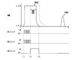
- FIG. 2 is a time chart showing processing executed by the control unit in the first embodiment.
- FIG. 3 is a configuration diagram of an ultrasonic sensor according to the second embodiment.
- FIG. 4 is a configuration diagram of an ultrasonic sensor according to the fifth embodiment.
- 5A is a time chart in the long-distance mode
- FIG. 5B is a time chart in the short-distance mode
- FIG. 6 is a configuration diagram of an ultrasonic sensor according to the sixth embodiment.
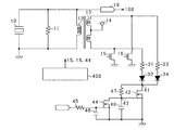
- FIG. 7 is a configuration diagram of an ultrasonic sensor according to the seventh embodiment.
- FIG. 8 is a time chart showing processing executed by the control unit in the seventh embodiment.
- the object detection apparatus is an ultrasonic sensor and is mounted on a moving body such as a vehicle.
- the ultrasonic sensor transmits ultrasonic waves to the surroundings of the moving body, receives the reflected waves reflected by the objects existing in the surroundings, and measures the time from transmission to reception, thereby measuring the distance between the moving body and the objects.
- FIG. 1 is a circuit diagram of an ultrasonic sensor according to the present embodiment.
- the ultrasonic sensor transmits ultrasonic waves by applying a voltage to the piezoelectric vibrator 10 and converts the energy of the reflected wave received by the piezoelectric vibrator 10 into a voltage.
- a first resistor 11 and a first coil 12 are connected to the piezoelectric vibrator 10 in parallel.
- the first coil 12 forms a transformer with the second coil 13 that is magnetically coupled.
- the second coil 13 includes a center tap, and a power source 14 is connected to the center tap.
- the voltage of the power supply 14 is 12V, for example.
- the first end of the second coil 13 is grounded via the first switch 15, and the second end of the second coil 13 is grounded via the second switch 16.
- the second coil 13, the first switch 15, and the second switch 16 constitute a drive circuit for the piezoelectric vibrator 10.
- the first end and the second end of the second coil 13 are connected by a series connection body of the third switch 17 and the second resistor 18.
- the voltage on the first coil 12 side is input to the control unit 100 via the amplifier 19, and the control unit 100 transmits a control signal to the first switch 15, the second switch 16, and the third switch 17.
- the control unit 100 is a computer that includes a CPU, ROM, RAM, I / O, and the like.
- the control unit 100 transmits an exploration wave, and controls until a predetermined time elapses from the transmission as one control cycle.
- the control unit 100 performs drive control in which the first switch 15 and the second switch 16 are alternately turned on to supply drive power. By doing so, the piezoelectric vibrator 10 is driven by being applied with voltages in the forward and reverse directions alternately.
- the reflected wave is received by the piezoelectric vibrator 10
- both the first switch 15 and the second switch 16 are turned off. By doing so, power is not supplied from the second coil 13 side to the first coil 12 side, and the piezoelectric vibrator 10 vibrates by receiving the reflected wave.
- reception of the reflected wave is detected.
- the control unit 100 When receiving the reflected wave, the control unit 100 calculates the distance from the object based on the time from the transmission of the exploration wave to the reception of the reflected wave, and transmits it to another control device. When the reflected wave is not detected before the predetermined time has elapsed since the transmission of the exploration wave, it is assumed that no object exists within the detection range. Note that the control unit 100 may obtain the time until reception of the reflected wave and transmit the time to another control device.
- the control unit 100 performs opening / closing control of the third switch 17 in addition to opening / closing control of the first switch 15 and the second switch 16.
- first switch 15 and the second switch 16 are turned off and the third switch 17 is turned on, both ends of the second coil 13 are short-circuited via the second resistor 18. Therefore, if a current remains on the first coil 12 side, a current flows on the second coil 13 side, and power is consumed by the second resistor 18 in addition to the first resistor 11.
- a circuit having an equivalent resistance value obtained by multiplying the resistance value of the second resistor 18 by the square of the turn ratio is connected to the first resistor 11 in parallel.
- the resistance value of the second resistor 18 is 500 ⁇ and the turns ratio of the first coil 12 and the second coil 13 is 4: 1, when the third switch 17 is turned on, the first resistor 11
- This is a circuit equivalent to a resistor having a resistance value of 8 k ⁇ connected in parallel.
- the third switch 17 is turned ON during a period when the reverberation of the piezoelectric vibrator 10 after the drive control occurs (reverberation time), and the first resistor 11, the first coil 12, the second coil 13, and the second resistor 18 are turned on.
- the resistance unit having a smaller combined resistance value than when only the first resistor 11 is connected in parallel, the consumption amount of reverberant power per hour can be increased and the reverberation time can be shortened.
- the third switch 17 is turned off, and control is performed to increase the resistance value of the resistance portion connected in parallel to the piezoelectric vibrator 10.
- both the first switch 15 and the second switch 16 are turned off, and the drive control of the piezoelectric vibrator 10 is finished.
- the third switch 17 is turned on in order to shorten the reverberation time.
- a closed circuit in which the second coil 13 and the second resistor 18 are connected in series is formed on the second coil 13 side.
- the 1st resistance 11 and the 2nd resistance 18 will be in a parallel connection state, and a synthetic
- the waveform of the exploration wave when the third switch 17 is not controlled is indicated by a broken line.
- the third switch 17 is turned off.
- the first resistor 11 is connected in parallel to the piezoelectric vibrator 10 and the second resistor 18 is not connected in parallel, so that the resistance value is increased.
- the piezoelectric vibrator 10 receives the reflected wave while waiting to receive the reflected wave, the power consumed by the resistor is reduced. Therefore, a reflected wave having a small amplitude such as a reflected wave reflected by an object existing at a long distance or a reflected wave reflected from an object having a low reflectance can be detected.
- the ultrasonic sensor according to this embodiment has the following effects.
- the power of reverberation can be consumed more quickly and the reverberation time can be shortened. Since the reflected wave reflected by the object cannot be detected within the reverberation time, the object existing at a short distance can be detected by reducing the reverberation time.
- the third switch 17 is turned on after the end of the reverberation time, and the resistance value of the resistor connected in parallel to the piezoelectric vibrator 10 is increased. As a result, it is possible to ensure the reception sensitivity of a reflected wave having a small amplitude, such as a reflected wave reflected by an object at a long distance or a reflected wave reflected by an object having a low reflectance.
- the piezoelectric vibrator 10 vibrates when a high voltage is applied. Therefore, when a switch is connected in series to a resistor connected in parallel to the piezoelectric vibrator 10, it is necessary to increase the withstand voltage of the switch.
- a series connection body of the third switch 17 and the second resistor 18 is provided in the low-voltage drive circuit, and the third switch 17 is turned on so that the piezoelectric vibrator 10 is connected in parallel. The combined resistance value is reduced. As a result, the third switch 17 having a small withstand voltage can be employed.
- the drive circuit of the piezoelectric vibrator 10 is in a standby state until the start of the next drive control after the drive control, and is not generally used.
- the first coil 12 and the second coil 13 that form the drive circuit of the piezoelectric vibrator 10 are used to form a resistance unit that shortens the reverberation time. Therefore, it is necessary to provide a resistance unit separately. Absent. Therefore, it is possible to reduce the circuit size and the manufacturing cost.
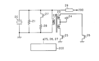
- FIG. 3 is a circuit diagram of the ultrasonic sensor according to the present embodiment.
- a first resistor 21 and a first coil 22 are connected to the piezoelectric vibrator 20 in parallel.
- the first coil 22 forms a transformer with the second coil 23 that is magnetically coupled.
- the second coil 23 includes a center tap, and a power source 24 is connected to the center tap.
- the first end of the second coil 23 is grounded via the first switch 25, and the second end of the second coil 23 is grounded via the second switch 26.
- a series connection body of a third switch 27 and a second resistor 28 is connected to the piezoelectric vibrator 20 in parallel. That is, the first resistor 21, the second resistor 28, and the third switch 27 constitute a resistor unit. Therefore, when the third switch 27 is turned on, a parallel connection body of the first resistor 21 and the second resistor 28 is connected in parallel to the piezoelectric vibrator 20, and the combined resistance value is the first resistor 21. It becomes smaller than the case where only is connected in parallel. That is, by turning on the third switch 27, it is possible to produce the same effect as when the third switch 17 is turned on in the first embodiment.
- the voltage on the first coil 22 side is input to the control unit 200 via the amplifier 29, and the control unit 200 supplies the first switch 25, the second switch 26, and the third switch 27. Send a control signal.
- the control of the first to third switches 25 to 27 executed by the control unit 200 is the same as that of the first embodiment, and a description thereof will be omitted.
- the circuit configuration is the same as that of the second embodiment, and the processing executed by the control unit 200 is partially different.
- the long-distance mode first mode
- a short distance mode second mode
- one control opportunity is taken until a predetermined time elapses after the transmission of the exploration wave. Then, at the end of one control opportunity, it is determined whether or not to switch between the long distance mode and the short distance mode.
- the OFF state of the third switch 27 is continued, and the resistance value connected in parallel to the piezoelectric vibrator 20 is increased. By doing so, the power consumed by the resistor per unit time is reduced and the reverberation time is lengthened. On the other hand, the electric power based on the reflected wave reflected by the object existing at a long distance becomes difficult to attenuate by the resistance, and the detection performance of the reflected wave can be improved.
- the ON state of the third switch 27 is continued, and the resistance value connected in parallel to the piezoelectric vibrator 20 is reduced. By doing so, the power consumed by the resistor per unit time increases and the reverberation time becomes shorter. Therefore, it is possible to detect a reflected wave reflected by an object existing at a short distance.
- the control unit 200 first continues to detect the object in the long-distance mode, and guarantees the detection performance for the object existing at a long distance.
- a reflected wave from an object existing at a long distance is continuously detected and the object approaches the ultrasonic sensor and the distance falls below a predetermined value (for example, 1 m)
- the mode is switched to the short distance mode and the reverberation time is shortened.
- the circuit configuration is the same as that of the second embodiment, and the processing executed by the control unit 200 is partially different.
- the control unit 200 performs control using the long-distance mode control and the short-distance mode control similar to those of the third embodiment.
- the control unit 200 first transmits a survey wave and receives a reflected wave by one of the long-distance mode and the short-distance mode.
- the search wave is transmitted and the reflected wave is received by the other control of the long-distance mode and the short-distance mode. Therefore, the position of an object that is difficult to detect by the long-distance mode control (an object located at a short distance) can be detected by the subsequent short-distance mode control.
- the position can be detected by an object that is difficult to detect in the short-distance mode control (an object located at a long distance), and the control that is subsequently performed by increasing the combined resistance.
- the short distance mode control may be performed a plurality of times after the long distance mode control a plurality of times. Further, the short distance mode control may be performed a plurality of times after the long distance mode control is performed once.
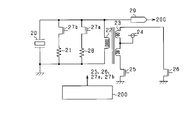
- FIG. 4 is a circuit diagram of the ultrasonic sensor according to the present embodiment.
- a third switch 27a is connected in series to the second resistor 28 connected in parallel to the piezoelectric vibrator 20.
- a fourth switch 27 b is connected in series to the first resistor 21 connected in parallel to the piezoelectric vibrator 20.
- the resistance value of the first resistor 21 is larger than the resistance value of the second resistor 28. That is, when both the third switch 27a and the fourth switch 27b are turned on, the resistance value connected in parallel to the piezoelectric vibrator 20 becomes the smallest, the third switch 27a is turned off, and the fourth switch 27b is turned on. In this case, the resistance value connected in parallel to the piezoelectric vibrator 20 is the largest.
- FIG. 5A is a time chart of the long distance mode executed by the ultrasonic sensor according to the present embodiment
- FIG. 5B is a time chart of the short distance mode.
- the use of the long distance mode and the short distance mode is performed in a manner similar to the third and fourth embodiments.
- the third switch 27a is turned off and the fourth switch 27b is turned on while power is being supplied to the piezoelectric vibrator 20 started at time t1. By doing so, it is possible to suppress power consumption at the resistor during power supply. Subsequently, when the supply of power ends at time t2, the third switch 27a is turned on and the fourth switch 27b is turned off. By doing so, the resistance value connected in parallel to the piezoelectric vibrator 20 can be reduced, and reverberation can be reduced early.
- the third switch 27a is turned on and the fourth switch 27b is turned off during the supply of power to the piezoelectric vibrator 20 started at time t1. By doing so, it is possible to suppress power consumption at the resistor during power supply. Subsequently, when the supply of power is completed at time t2, both the third switch 27a and the fourth switch 27b are turned on. By doing so, the resistance value connected in parallel to the piezoelectric vibrator 20 can be reduced, and reverberation can be reduced early. At this time, the time during which power is supplied to the piezoelectric vibrator 20, that is, the interval between the time t1 and the time t2 is set shorter than that in the long-distance mode. By doing so, the reverberation of the piezoelectric vibrator 20 can be further reduced, and thereby the reverberation time can be shortened.
- the switching patterns shown in FIGS. 5A and 5B are merely examples, and it is sufficient that the resistance value in the long-distance mode is larger than the resistance value in the short-distance mode. Further, as in the first and second embodiments, after the reverberation ends, control for increasing the resistance value may be performed.
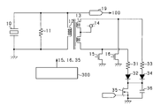
- FIG. 6 is a circuit diagram of the ultrasonic sensor according to the present embodiment.
- a first resistor 11 and a first coil 12 are connected in parallel to the piezoelectric vibrator 10, and the first coil 12 is transformed by a second coil 13 that is magnetically coupled. Is configured.
- One end of the second coil 13 is connected to the anode of the first diode 32 via the second resistor 31, and the other end of the second coil 13 is connected to the anode of the second diode 34 via the third resistor 33. It is connected.
- the cathodes of the first and second diodes 32 and 34 are grounded via the third switch 35.
- the control unit 300 transmits a control signal to the first switch 15, the second switch 16, and the third switch 35. Note that the control timings of the first switch 15, the second switch 16, and the third switch 35 are the same as those in the first embodiment, and thus the description thereof is omitted.
- the ultrasonic sensor according to the present embodiment has an effect similar to that of the first embodiment.
- FIG. 7 is a circuit diagram of the ultrasonic sensor according to the present embodiment.
- a first resistor 11 and a first coil 12 are connected in parallel to the piezoelectric vibrator 10, and the first coil 12 is transformed by a second coil 13 that is magnetically coupled. Is configured.
- One end of the second coil 13 is connected to the anode of the first diode 32 via the second resistor 31, and the other end of the second coil 13 is connected to the anode of the second diode 34 via the third resistor 33. It is connected.
- the cathode of the first diode 32 and the cathode of the second diode 34 are connected to the first connection point 41.
- the first connection point 41 is grounded via the third switch 42.
- the gate which is the conduction control terminal of the third switch 42 is grounded via the second connection point 43 and the auxiliary switch 44.
- a control signal is input to the gate of the auxiliary switch 44 via a resistor 45.
- a capacitor 46 is provided between the gate of the auxiliary switch 44 and the grounding part.
- the first connection point 41 and the second connection point 43 are connected via a fourth resistor 47, and the second connection point 43 is grounded via a capacitor 48. That is, an RC series circuit is configured by the fourth resistor 47 and the capacitor 48, and the RC series circuit is connected in parallel to the third switch 42.
- the control unit 400 transmits a control signal to the first switch 15, the second switch 16, and the auxiliary switch 44.
- the timing of control of the first switch 15 and the second switch 16 is the same as in the first embodiment.
- the control timing of the auxiliary switch 44 is the same as the control timing of the third switch 17 in the first embodiment.
- the control unit 400 turns on the auxiliary switch 44, the gate voltage of the third switch 42 becomes larger than the threshold value, and the third switch 42 is turned on. At this time, although the electric potential between both ends of the second coil 13 oscillates around 0 V, the RC series circuit constituted by the fourth resistor 47 and the capacitor 48 is connected in parallel to the third switch 42. The gate voltage of the 3 switch 42 is maintained at a value larger than the threshold value. Therefore, the ON state of the third switch 42 is maintained.
- the third switch 42 is also turned off accordingly.
- the potential difference between both ends of the second coil 13 is gradually increased from 0 V by the RC series circuit configured by the fourth resistor 47 and the capacitor 48 connected in parallel to the third switch 42.
- the change is gentle, so that the generation of noise on the first coil 12 side due to the sudden voltage change is suppressed. can do.
- the ultrasonic sensor according to the present embodiment has the following effects in addition to the effects equivalent to the effects exhibited by the ultrasonic sensor according to the sixth embodiment.
- the RC series circuit composed of the fourth resistor 47 and the capacitor 48 is connected in parallel to the third switch 42, the voltage on the second coil 13 side of the transformer when the third switch 42 is turned OFF Change can be moderated. Therefore, it is possible to suppress the generation of noise based on a rapid change in voltage. If noise is generated when the third switch 42 is turned OFF, the reflected wave reception accuracy is lowered until the noise is attenuated. Therefore, the reception of the reflected wave is waited after the noise is sufficiently attenuated. Become. For this reason, the time until standby for reception increases, and it becomes difficult to detect an object at a short distance.
- the RC series circuit composed of the fourth resistor 47 and the capacitor 48 can suppress the noise indicated by the broken line in FIG. Therefore, the detection range of the ultrasonic sensor can be expanded.
- a series connection body of the second resistor 18 and the third switch 17 is provided in the drive circuit, and the first coil 12 and the second coil 13 used when driving the piezoelectric vibrator 10 are used. The reverberation time is reduced. This point.
- a pair of coils different from the first coil 12 and the second coil 13 may be further provided, and the resistor portion may be configured by a series connection body of a resistor and a switch connected to one of the pair of coils.
- the third switch 17 may be turned off after a predetermined time has elapsed from the time t2 when the supply of power to the piezoelectric vibrator 10 is finished.
- the predetermined time is predetermined, but may be corrected according to various conditions such as temperature and humidity.
- the combined resistance of the resistors connected in parallel to the piezoelectric vibrator 20 is changed by connecting resistors in parallel and changing the connection state.
- a variable resistor may be connected in parallel to the piezoelectric vibrator 20 to change the resistance value.
- the coil constituting the primary side of the transformer that is, the second coil 13 is provided with a center tap, but a coil without a center tap may be used.
- power may be supplied using a power supply circuit that can alternately apply a forward voltage and a reverse voltage.
- a series connection body of a switch and a resistor may be further provided in the series connection body of the third switch 17 and the second resistor 18 so that the combined resistance value can be changed in a plurality of stages.
- the second resistor 18 may be a variable resistor.
- a resistor in addition to the first resistor 21 and the second resistor 28, a resistor may be further connected in parallel, and a switch for switching the connection state of the resistor may be provided.
- control shown in the fifth embodiment for shortening the power supply time in the short-distance mode than in the long-distance mode may be applied to the third and fourth embodiments.
- the second resistor 31 and the third resistor are connected to both ends of the second coil 13, and the second resistor 31 and the third resistor 33 are grounded via the third switch 35.
- the specific configuration for connecting the both ends of the second coil 13 to the resistor and the switch is not limited to the above embodiment.
- each end of the second coil 13 may be connected to one resistor via a diode, and the resistor may be grounded via a switch.
- a switch may be provided between the diode and the resistor. That is, a resistor connected via a switch may be provided between each end of the second coil and the grounding portion.
- the auxiliary switch 44, the fourth resistor 47, and the capacitor 48 constitute a delay circuit that delays switching of the open / close state of the third switch 42. It is not limited to.
- the distance from the object is measured by the ultrasonic sensor, but may be used to detect the presence of the object within a predetermined distance.
- the ultrasonic sensor is mounted on a moving body such as a vehicle, but the mounting target is not limited to this. It is good also as what detects the distance with the object which mounts in a stationary object etc. and exists around the stationary object.
Landscapes
- Engineering & Computer Science (AREA)
- Radar, Positioning & Navigation (AREA)
- Remote Sensing (AREA)
- Physics & Mathematics (AREA)
- Computer Networks & Wireless Communication (AREA)
- General Physics & Mathematics (AREA)
- Acoustics & Sound (AREA)
- Measurement Of Velocity Or Position Using Acoustic Or Ultrasonic Waves (AREA)
Abstract
圧電振動子10を駆動して探査波を送信し、物体により反射された反射波を受信する物体検知装置であって、圧電振動子10と、圧電振動子10を駆動する駆動電力を供給する駆動回路と、圧電振動子10と並列に接続され、抵抗値が可変である抵抗部と、を備える。
Description
本出願は、2016年3月18日に出願された日本出願番号2016-055826号に基づくもので、ここにその記載内容を援用する。
本開示は、探査波を送信し、物体により反射された反射波を受信する物体検知装置に関する。
探査波を送信し、物体により反射された反射波を受信してその物体との距離を検知する物体検知装置では、探査波の送信時に残響が発生する。この残響のエネルギは、一般的に反射波のエネルギよりも著しく大きいため、残響が生じている時間(残響時間)に反射波を受信したとしても、その反射波を検知することが困難である。
この残響時間を短縮するものとして、特許文献1に記載の超音波センサがある。特許文献1に記載の超音波センサでは、圧電振動子の駆動後に、残響とは逆位相のパルス信号を送信し、そのパルス信号により残響を抑制している。
特許文献1に記載の超音波センサでは、逆位相のパルス信号を出力するタイミングがずれれば、残響を増幅することにもつながる。また、パルス信号の振幅が必要以上に大きければ、残響を打ち消すことはできるものの、そのパルス信号により圧電振動子が駆動されることとなる。すなわち、逆位相のパルス信号を精度よく生成する必要があり、これは、ロバスト性を確保することが困難であることを意味する。
本開示は、上記課題を解決するためになされたものであり、その主たる目的は、物体の検知性能を向上させることができる物体検知装置を提供することにある。
本開示は、圧電振動子を駆動して探査波を送信し、物体により反射された反射波を受信する超音波センサであって、圧電振動子と、圧電振動子を駆動する駆動電力を供給する駆動回路と、圧電振動子と並列に接続され、抵抗値が可変である抵抗部と、を備える。
上記構成では、探査波の送信時における圧電振動子の駆動後の残響を低減したい場合に、圧電振動子に並列接続した抵抗部の抵抗値を低下させることで、残響による電力を抵抗部で消費することができる。これにより、残響が生ずる時間を短縮することができ、近距離の物体により反射された反射波も検知することが可能となる。一方、反射波の受信時等には、圧電振動子に並列接続した抵抗部の抵抗値を増加させることで、抵抗部により消費される電力を低下することができる。これにより、遠距離の物体により反射された反射波や、反射率の小さい物体により反射された反射波等の受信感度を担保することができる。したがって、近距離の物体の検知性能と遠距離の物体の検知性能とを両立することができる。
本開示についての上記目的およびその他の目的、特徴や利点は、添付の図面を参照しながら下記の詳細な記述により、より明確になる。その図面は、
図1は、第1実施形態に係る超音波センサの構成図であり、
図2は、第1実施形態における制御部が実行する処理を示すタイムチャートであり、
図3は、第2実施形態に係る超音波センサの構成図であり、
図4は、第5実施形態に係る超音波センサの構成図であり、
図5は、(a)は遠距離モードでのタイムチャートであり、(b)は近距離モードでのタイムチャートであり、
図6は、第6実施形態に係る超音波センサの構成図であり、
図7は、第7実施形態に係る超音波センサの構成図であり、
図8は、第7実施形態における制御部が実行する処理を示すタイムチャートである。
以下、各実施形態を図面に基づいて説明する。なお、以下の各実施形態相互において、互いに同一もしくは均等である部分には、図中、同一符号を付しており、同一符号の部分についてはその説明を援用する。
<第1実施形態>
本実施形態に係る物体検知装置は超音波センサであり、車両等の移動体に搭載されるものである。超音波センサは、超音波を移動体の周囲に送信し、周囲に存在する物体により反射された反射波を受信し、送信から受信までの時間を測定することにより、移動体と物体との距離を求める。
本実施形態に係る物体検知装置は超音波センサであり、車両等の移動体に搭載されるものである。超音波センサは、超音波を移動体の周囲に送信し、周囲に存在する物体により反射された反射波を受信し、送信から受信までの時間を測定することにより、移動体と物体との距離を求める。
図1は、本実施形態に係る超音波センサの回路図である。超音波センサは、圧電振動子10への電圧の印加により超音波を送信し、圧電振動子10が受信した反射波のエネルギを電圧へ変換するものである。この圧電振動子10には第1抵抗11、及び、第1コイル12が並列接続されている。第1コイル12は、磁気的に結合する第2コイル13とによりトランスを構成している。第2コイル13はセンタータップを備えており、そのセンタータップに電源14が接続されている。この電源14の電圧は、例えば12Vである。
第2コイル13の第1端は、第1スイッチ15を介して接地されており、第2コイル13の第2端は、第2スイッチ16を介して接地されている。この第2コイル13、第1スイッチ15、及び第2スイッチ16により圧電振動子10の駆動回路を構成する。加えて、第2コイル13の第1端と第2端とは、第3スイッチ17と第2抵抗18との直列接続体により接続されている。
第1コイル12側の電圧は、アンプ19を介して制御部100へ入力され、制御部100は、第1スイッチ15、第2スイッチ16、及び第3スイッチ17へ制御信号を送信する。この制御部100は、CPU、ROM、RAM、I/O等を備えたコンピュータである。
制御部100は、探査波を送信し、送信から所定時間が経過するまでを1制御周期として制御する。制御部100は、圧電振動子10を駆動して超音波を送信する際には、第1スイッチ15と第2スイッチ16とを交互にONとして駆動電力を供給する駆動制御を行う。こうすることで、圧電振動子10には順方向と逆方向の電圧が交互に印加されて駆動する。圧電振動子10により反射波を受信する際には、第1スイッチ15と第2スイッチ16とを共にOFFとする。こうすることで、第2コイル13側から第1コイル12側へと電力は供給されず、圧電振動子10は反射波を受信することにより振動する。その振動により生ずる電力に基づく電圧がアンプ19を介して制御部100へ入力されることにより、反射波の受信を検知することとなる。
制御部100は、反射波を受信すれば、探査波の送信から反射波の受信までの時間に基づいて物体との距離を算出し、他の制御装置へ送信する。探査波の送信から所定時間が経過するまでに反射波を検知しない場合には、検知範囲内に物体が存在しないものとする。なお、制御部100が反射波の受信までの時間を求め、その時間を他の制御装置へ送信するものとしてもよい。
制御部100は、第1スイッチ15及び第2スイッチ16の開閉制御に加えて、第3スイッチ17の開閉制御を行う。第1スイッチ15及び第2スイッチ16をOFFとし、第3スイッチ17をONとした場合には、第2コイル13の両端が第2抵抗18を介して短絡されることとなる。したがって、第1コイル12側に電流が残存していれば、第2コイル13側に電流が流れ、第1抵抗11に加えて第2抵抗18でも電力が消費されることとなる。このとき、第2抵抗18の抵抗値に巻数比の自乗を乗算した抵抗値を有する抵抗を第1抵抗11に並列接続したものと等価の回路となる。すなわち、第2抵抗18の抵抗値を500Ωとし、第1コイル12と第2コイル13との巻数比を4:1とすれば、第3スイッチ17をONとした場合には、第1抵抗11に抵抗値が8kΩの抵抗を並列接続したものと等価の回路となる。
したがって、駆動制御後の圧電振動子10の残響が生じている期間(残響時間)に第3スイッチ17をONとし、第1抵抗11、第1コイル12、第2コイル13、及び第2抵抗18により、第1抵抗11のみが並列接続される場合よりも合成抵抗値が小さい抵抗部を構成することにより、残響の電力の時間当たりの消費量を増加させ、残響時間を短縮することができる。一方で、合成抵抗値が小さい状態で、振幅の小さい反射波を受信した場合、その反射波に基づく電力が抵抗により消費され、検知が困難となる場合がある。したがって、圧電振動子10の残響が終了すれば、第3スイッチ17をOFFとし、圧電振動子10に並列接続される抵抗部の抵抗値を大きくする制御を行うものとする。
続いて、制御部100が実行する処理を図2のタイムチャートを用いて説明する。まず、時刻t1において圧電振動子10の駆動の開始指令が発せられると、第1スイッチ15と第2スイッチ16とを交互にONとして駆動電力を供給する、圧電振動子10の駆動制御が行われる。この駆動制御により、圧電振動子10には極性の異なる電圧が交互に印加され、圧電振動子10は駆動されて超音波である探査波を送信する。このとき、探査波の振幅は、検知可能な限界の値であるh_maxよりも大きい値となる。この駆動制御が行われる時間は予め定められた時間であり、時刻t2まで継続される。
時刻t2では、第1スイッチ15及び第2スイッチ16を共にOFFとし、圧電振動子10の駆動制御を終了する。このとき、圧電振動子10には残響が生じているため、残響時間を短縮すべく、第3スイッチ17をONとする。第3スイッチ17をONとすることにより、第2コイル13側では、第2コイル13と第2抵抗18が直列接続された閉回路が形成される。これにより、第1抵抗11と第2抵抗18は並列接続状態となり、合成抵抗値は小さくなる。ゆえに、第1抵抗11及び第2抵抗18により消費される電力量が増加し、残響時間を短縮することができる。なお、図2において、第3スイッチ17の制御を行わない場合の探査波の波形を、破線で示している。
第3スイッチ17をONとする制御を継続し、時刻t3で振幅が閾値であるh_minよりも小さくなれば、残響の振幅が十分小さく反射波の検知が可能であるため、第3スイッチ17をOFFとする。こうすることにより、圧電振動子10には第1抵抗11が並列接続され第2抵抗18は並列接続されないこととなるため、抵抗値は大きくなる。これにより、反射波の受信待機中に圧電振動子10が反射波を受信した際に、抵抗で消費される電力が小さくなる。したがって、遠距離に存在する物体により反射された反射波や、反射率の小さい物体から反射された反射波等、振幅の小さい反射波も検知することができるようになる。
上記構成により、本実施形態に係る超音波センサは、以下の効果を奏する。
・圧電振動子10の駆動制御の終了後に第3スイッチ17をONとすることで、残響の電力をより早く消費することができ、残響時間を短縮することができる。残響時間内では物体により反射された反射波を検知することができないため、残響時間の短縮により、近距離に存在する物体の検知が可能となる。
・残響時間の終了後に第3スイッチ17をONとし、圧電振動子10に並列接続された抵抗の抵抗値を増加させている。これにより、遠距離の物体により反射された反射波や、反射率の小さい物体に反射された反射波等、振幅の小さい反射波の受信感度を担保することができる。
・圧電振動子10は、高圧の電圧の印加により振動するものであるため、その圧電振動子10に並列接続した抵抗にスイッチを直列接続した場合、スイッチの耐圧を大きくする必要がある。この点、本実施形態では、低圧の駆動回路に第3スイッチ17と第2抵抗18との直列接続体を設け、第3スイッチ17をONとすることにより、圧電振動子10に並列接続される合成抵抗値を小さくするものとしている。これにより、第3スイッチ17として耐圧が小さいものを採用することができる。
・圧電振動子10の駆動回路は、駆動制御後は、次の駆動制御の開始まで待機状態となり、一般的には使用されることがない。本実施形態では、圧電振動子10の駆動回路を構成する第1コイル12及び第2コイル13を用いて、残響時間を短縮する抵抗部を構成するものとしているため、抵抗部を別途設ける必要がない。よって、回路の小型化及び製造コストの低減を実現することができる。
<第2実施形態>
本実施形態に係る超音波センサは、第1実施形態に係る超音波センサと回路構成が一部異なっている。図3は、本実施形態に係る超音波センサの回路図である。
本実施形態に係る超音波センサは、第1実施形態に係る超音波センサと回路構成が一部異なっている。図3は、本実施形態に係る超音波センサの回路図である。
圧電振動子20には第1抵抗21、及び、第1コイル22が並列接続されている。第1コイル22は、磁気的に結合する第2コイル23とによりトランスを構成している。第2コイル23はセンタータップを備えており、そのセンタータップに電源24が接続されている。第2コイル23の第1端は、第1スイッチ25を介して接地されており、第2コイル23の第2端は、第2スイッチ26を介して接地されている。
加えて、圧電振動子20には、第3スイッチ27と第2抵抗28との直列接続体が並列接続されている。すなわち、第1抵抗21、第2抵抗28及び第3スイッチ27により抵抗部を構成している。したがって、第3スイッチ27をONとすれば、圧電振動子20には第1抵抗21と第2抵抗28との並列接続体が並列接続されることとなり、その合成抵抗値は、第1抵抗21のみが並列接続される場合よりも小さくなる。すなわち、第3スイッチ27をONとすることで、第1実施形態において第3スイッチ17をONとする場合と同様の効果を生じさせることができる。
第1コイル22側の電圧は、第1実施形態と同様に、アンプ29を介して制御部200へ入力され、制御部200は、第1スイッチ25、第2スイッチ26、及び第3スイッチ27へ制御信号を送信する。なお、制御部200が実行する第1~第3スイッチ25~27の制御については、第1実施形態に準ずるものであるため、その説明を省略する。
<第3実施形態>
本実施形態では、回路構成は第2実施形態と同様であり、制御部200が実行する処理が一部異なっている。本実施形態では、残響時間が長くなることを許容しつつ、遠距離に存在する物体に反射された反射波の検知性能を向上させる遠距離モード(第1モード)と、残響時間を短縮し、近距離に存在する反射波も検知可能とした近距離モード(第2モード)とを行うものとする。遠距離モードでの制御及び近距離モードでの制御は、それぞれ、探査波の送信しその送信から所定時間が経過するまでを1制御機会とする。そして、1制御機会の終了時等に、遠距離モードと近距離モードとを切り替えるか否かを判定する。
本実施形態では、回路構成は第2実施形態と同様であり、制御部200が実行する処理が一部異なっている。本実施形態では、残響時間が長くなることを許容しつつ、遠距離に存在する物体に反射された反射波の検知性能を向上させる遠距離モード(第1モード)と、残響時間を短縮し、近距離に存在する反射波も検知可能とした近距離モード(第2モード)とを行うものとする。遠距離モードでの制御及び近距離モードでの制御は、それぞれ、探査波の送信しその送信から所定時間が経過するまでを1制御機会とする。そして、1制御機会の終了時等に、遠距離モードと近距離モードとを切り替えるか否かを判定する。
遠距離モードでは、第3スイッチ27のOFF状態を継続し、圧電振動子20に並列接続される抵抗値を大きくする。こうすることにより、単位時間当たりに抵抗で消費される電力は小さくなり、残響時間は長くなる。一方で、遠距離に存在する物体に反射された反射波に基づく電力が抵抗で減衰しづらくなり、その反射波の検知性能を向上させることができる。
近距離モードでは、第3スイッチ27のON状態を継続し、圧電振動子20に並列接続される抵抗値を小さくする。こうすることにより、単位時間当たりに抵抗で消費される電力は増加し、残響時間は短くなる。ゆえに、近距離に存在する物体により反射された反射波を検知可能となる。
制御部200は、まず、遠距離モードでの物体の検知を継続し、遠距離に存在する物体についての検知性能を担保する。遠距離に存在する物体からの反射波を継続して検知し、物体が超音波センサへ接近して距離が所定値(例えば1m)を下回れば、近距離モードに切り替え、残響時間を短縮する。このように制御することにより、近距離の物体に対する検知性能と遠距離の物体に対する検知性能とを両立することができる。
<第4実施形態>
本実施形態では、回路構成は第2実施形態と同様であり、制御部200が実行する処理が一部異なっている。加えて、制御部200は、第3実施形態と同様の遠距離モードの制御と近距離モードの制御とを用いた制御を行う。
本実施形態では、回路構成は第2実施形態と同様であり、制御部200が実行する処理が一部異なっている。加えて、制御部200は、第3実施形態と同様の遠距離モードの制御と近距離モードの制御とを用いた制御を行う。
制御部200は、まず、遠距離モードと近距離モードとの一方の制御により、探査波の送信及び反射波の受信を行う。続く制御周期では、遠距離モードと近距離モードとの他方の制御により、探査波の送信及び反射波の受信を行う。したがって、遠距離モードの制御では検知が困難な物体(近距離に位置する物体)については、続いて行われる近距離モードの制御により、その位置を検出することができる。一方、近距離モードの制御では検知が困難な物体(遠距離に位置する物体)、続いて行われる合成抵抗を大きくした制御により、その位置を検知することができる。このように制御することにより、近距離の物体に対する検知性能と遠距離の物体に対する検知性能とを両立することができる。
なお、遠距離モードの制御を複数回行った後に近距離モードの制御を複数回行うものとしてもよい。また、遠距離モードの制御を1回行った後に近距離モードの制御を複数回行うものとしてもよい。
<第5実施形態>
本実施形態に係る超音波センサは、回路の一部が第2実施形態と異なっている。図4は、本実施形態に係る超音波センサの回路図である。圧電振動子20に並列接続される第2抵抗28には、第2実施形態と同様に、第3スイッチ27aが直列接続されている。加えて、圧電振動子20に並列接続される第1抵抗21には、第4スイッチ27bが直列接続される。このように回路を構成することで、圧電振動子20に第1抵抗21のみが並列接続される状態、第2抵抗28のみが接続される状態、及び第1抵抗21及び第2抵抗28が共に並列接続される状態の3通りの状態を選択することが可能となる。なお、その他の構成については第2実施形態と同様であるため、その説明を省略する。
本実施形態に係る超音波センサは、回路の一部が第2実施形態と異なっている。図4は、本実施形態に係る超音波センサの回路図である。圧電振動子20に並列接続される第2抵抗28には、第2実施形態と同様に、第3スイッチ27aが直列接続されている。加えて、圧電振動子20に並列接続される第1抵抗21には、第4スイッチ27bが直列接続される。このように回路を構成することで、圧電振動子20に第1抵抗21のみが並列接続される状態、第2抵抗28のみが接続される状態、及び第1抵抗21及び第2抵抗28が共に並列接続される状態の3通りの状態を選択することが可能となる。なお、その他の構成については第2実施形態と同様であるため、その説明を省略する。
なお、第1抵抗21の抵抗値は第2抵抗28の抵抗値よりも大きいものとする。すなわち、第3スイッチ27a及び第4スイッチ27bを共にONとした場合に、圧電振動子20に並列接続される抵抗値が最も小さくなり、第3スイッチ27aをOFFとし第4スイッチ27bをONとした場合に、圧電振動子20に並列接続される抵抗値が最も大きくなる。
図5(a)は、本実施形態に係る超音波センサで実行する遠距離モードのタイムチャートであり、図5(b)は近距離モードのタイムチャートである。この遠距離モードと近距離モードの使い分けは、第3、第4実施形態に準ずる様態で行われる。
遠距離モードでは、時刻t1に開始される圧電振動子20への電力の供給中には第3スイッチ27aをOFFとし、第4スイッチ27bをONとする。こうすることにより、電力の供給中における抵抗での電力消費を抑制することができる。続いて、時刻t2で電力の供給が終了すれば、第3スイッチ27aをONとし第4スイッチ27bをOFFとする。こうすることにより、圧電振動子20に並列接続される抵抗値を小さくし、残響を早期に減少させることができる。
近距離モードでは、時刻t1に開始される圧電振動子20への電力の供給中には第3スイッチ27aをONとし、第4スイッチ27bをOFFとする。こうすることにより、電力の供給中における抵抗での電力消費を抑制することができる。続いて、時刻t2で電力の供給が終了すれば、第3スイッチ27a及び第4スイッチ27bを共にONとする。こうすることにより、圧電振動子20に並列接続される抵抗値を小さくし、残響を早期に減少させることができる。このとき、圧電振動子20へ電力が供給される時間、すなわち時刻t1と時刻t2の間隔を、遠距離モードよりも短くしている。こうすることにより、圧電振動子20の残響をより小さくすることができ、それにより残響時間を短縮することができる。
なお、図5(a)及び(b)で示したスイッチングパターンはあくまで一例であり、遠距離モードでの抵抗値が近距離モードでの抵抗値よりも大きくなっていればよい。また、第1、第2実施形態のごとく、残響の終了後には、抵抗値を大きくする制御を行うものとしてもよい。
<第6実施形態>
本実施形態に係る超音波センサは、回路構成の一部が上記各実施形態に係る超音波センサと異なっている。図6は、本実施形態に係る超音波センサの回路図である。
本実施形態に係る超音波センサは、回路構成の一部が上記各実施形態に係る超音波センサと異なっている。図6は、本実施形態に係る超音波センサの回路図である。
圧電振動子10には、第1実施形態と同様に、第1抵抗11、及び、第1コイル12が並列接続されており、第1コイル12は磁気的に結合する第2コイル13とによりトランスを構成している。
第2コイル13の一端は、第2抵抗31を介して第1ダイオード32のアノードに接続されており、第2コイル13の他端は、第3抵抗33を介して第2ダイオード34のアノードに接続されている。これら第1、第2ダイオード32,34のカソードは、第3スイッチ35を介して接地されている。
制御部300は、第1スイッチ15、第2スイッチ16、及び第3スイッチ35へ制御信号を送信する。なお、第1スイッチ15、第2スイッチ16、及び第3スイッチ35の制御のタイミングは、第1実施形態と同等であるため、その説明を省略する。
上記構成により、本実施形態に係る超音波センサは、第1実施形態に準ずる効果を奏する。
<第7実施形態>
本実施形態に係る超音波センサは、回路構成の一部が上記各実施形態に係る超音波センサと異なっている。図7は、本実施形態に係る超音波センサの回路図である。
本実施形態に係る超音波センサは、回路構成の一部が上記各実施形態に係る超音波センサと異なっている。図7は、本実施形態に係る超音波センサの回路図である。
圧電振動子10には、第1実施形態と同様に、第1抵抗11、及び、第1コイル12が並列接続されており、第1コイル12は磁気的に結合する第2コイル13とによりトランスを構成している。
第2コイル13の一端は、第2抵抗31を介して第1ダイオード32のアノードに接続されており、第2コイル13の他端は、第3抵抗33を介して第2ダイオード34のアノードに接続されている。第1ダイオード32のカソード及び第2ダイオード34のカソードは、第1接続点41に接続されている。その第1接続点41は、第3スイッチ42を介して接地されている。
第3スイッチ42の導通制御端子であるゲートは、第2接続点43、補助スイッチ44を介して接地されている。補助スイッチ44のゲートへは、抵抗45を介して制御信号が入力されるように構成されている。また、補助スイッチ44のゲートと接地部位間には、コンデンサ46が設けられている。
第1接続点41と第2接続点43とは、第4抵抗47を介して接続されており、第2接続点43は、コンデンサ48を介して接地されている。すなわち、第4抵抗47とコンデンサ48とによりRC直列回路を構成しており、そのRC直列回路が第3スイッチ42に対して並列接続されている。
制御部400は、第1スイッチ15、第2スイッチ16、及び補助スイッチ44へ制御信号を送信する。第1スイッチ15及び第2スイッチ16の制御のタイミングは、第1実施形態と同等である。また、補助スイッチ44の制御のタイミングは、第1実施形態における第3スイッチ17の制御のタイミングと同等である。
制御部400が補助スイッチ44をONとすれば、第3スイッチ42のゲート電圧が閾値よりも大きくなり、第3スイッチ42がONとなる。このとき、第2コイル13の両端間の電位は0Vを中心として振動するものの、第4抵抗47とコンデンサ48とにより構成されるRC直列回路が第3スイッチ42に並列接続されているため、第3スイッチ42のゲート電圧は閾値よりも大きい値に維持される。そのため、第3スイッチ42のON状態が維持される。
制御部400が補助スイッチ44をOFFとすれば、それに伴い第3スイッチ42もOFFとなる。このとき、第3スイッチ42に並列接続される第4抵抗47とコンデンサ48とにより構成されるRC直列回路により、第2コイル13の両端間の電位差は、0Vから緩やかに上昇することとなる。すなわち、トランスの第2コイル13側の電圧変化を第1コイル12で増幅したとしても、その変化は緩やかであるため、急激な電圧変化に起因する第1コイル12側でのノイズの発生を抑制することができる。
続いて、本実施形態に係る制御部400が実行する処理を図8のタイムチャートを用いて説明する。上述した通り、第2コイル13の両端間の電位差は、緩やかに増加するため、図8において破線で示したノイズの発生が抑制される。
上記構成により、本実施形態に係る超音波センサは、第6実施形態に係る超音波センサが奏する効果に準ずる効果に加えて、以下の効果を奏する。
・第3スイッチ42に、第4抵抗47とコンデンサ48とにより構成されるRC直列回路を並列接続しているため、第3スイッチ42をOFFとした際のトランスの第2コイル13側の電圧の変化を緩やかにすることができる。そのため、電圧の急激な変化に基づくノイズの発生を抑制することができる。第3スイッチ42をOFFとした際にノイズが生じていれば、そのノイズが減衰するまでは反射波の受信精度が低下するため、ノイズが十分に減衰した後に反射波の受信待機を行うこととなる。そのため、受信待機までの時間が延び、近距離の物体の検知が困難となる。この点、第4抵抗47とコンデンサ48とにより構成されるRC直列回路により、図8の破線で示したノイズを抑制できるため、より近距離の物体の位置も精度よく検知できる。したがって、超音波センサの検知範囲を拡大することができる。
<変形例>
・第1実施形態において、駆動回路中に第2抵抗18と第3スイッチ17との直列接続体を設け、圧電振動子10の駆動の際に用いられる第1コイル12及び第2コイル13を用いて、残響時間を低減するものとしている。この点。第1コイル12及び第2コイル13とは異なる一対のコイルをさらに設け、その一対のコイルの一方に接続された抵抗とスイッチの直列接続体により抵抗部を構成するものとしてもよい。
・第1実施形態において、駆動回路中に第2抵抗18と第3スイッチ17との直列接続体を設け、圧電振動子10の駆動の際に用いられる第1コイル12及び第2コイル13を用いて、残響時間を低減するものとしている。この点。第1コイル12及び第2コイル13とは異なる一対のコイルをさらに設け、その一対のコイルの一方に接続された抵抗とスイッチの直列接続体により抵抗部を構成するものとしてもよい。
・第1実施形態において、第3スイッチ17をOFFとする制御を行う契機として、波高が閾値であるh_minを下回ることを採用した。この点、圧電振動子10への電力の供給を終了する時刻t2から所定時間経過後に、第3スイッチ17をOFFするものとしてもよい。なお、この所定時間は予め定められたものであるが、気温や湿度等の諸条件により補正を行うものとしてもよい。
・第2実施形態~第5実施形態において、抵抗を並列接続し、その接続様態を変更することにより圧電振動子20に並列接続される抵抗の合成抵抗を変更するものとした。この点、圧電振動子20に可変抵抗を並列接続し、その抵抗値を変更するものとしてもよい。
・各実施形態において、トランスの一次側を構成するコイル、すなわち第2コイル13について、センタータップが設けられているものとしたが、センタータップが設けられないコイルを用いてもよい。この場合には、順方向の電圧と逆方向の電圧とを交互に印加することができる電源回路を用いて電力を供給するものとすればよい。
・第1実施形態において、第3スイッチ17と第2抵抗18との直列接続体に、さらにスイッチと抵抗との直列接続体を設け、合成抵抗値を複数段階に変更可能としてもよい。また、第2抵抗18を可変抵抗としてもよい。
・第2~第5実施形態において、第1抵抗21及び第2抵抗28に加えてさらに抵抗を並列接続し、その抵抗の接続状態を切り替えるスイッチを設けるものとしてもよい。
・第5実施形態で示した、近距離モードにおける電力の供給時間を遠距離モードよりも短くする制御を第3、第4実施形態に適用してもよい。
・第6、第7実施形態では、第2コイル13の両端のそれぞれに第2抵抗31及び第3抵抗が接続され、それら第2抵抗31、第3抵抗33が第3スイッチ35を介して接地されている。この点、第2コイル13の両端のそれぞれと、抵抗及びスイッチとを接続する具体的構成は、上記実施形態に限られない。例えば、第2コイル13の両端のそれぞれをダイオードを介してひとつの抵抗に接続し、その抵抗をスイッチを介して接地する構成としてもよい。また、ダイオードと抵抗との間にスイッチを設けてもよい。すなわち、第2コイルの両端のそれぞれと接地部位との間に、スイッチを介して接続される抵抗を備えていればよい。
・第7実施形態では、補助スイッチ44、第4抵抗47、及びコンデンサ48により、第3スイッチ42の開閉状態の切り替えを遅延させる遅延回路を構成するものとしたが、遅延回路の構成は、これに限られることはない。
・実施形態では超音波センサにより物体との距離を計測するものとしたが、所定距離以内における物体の存在を検知するために用いるものとしてもよい。
・実施形態では、超音波センサを車両等の移動体に搭載するものとしたが、搭載対象はこれに限られない。静止物等に搭載し、その静止物の周囲に存在する物体との距離を検出するものとしてもよい。
本開示は、実施例に準拠して記述されたが、本開示は当該実施例や構造に限定されるものではないと理解される。本開示は、様々な変形例や均等範囲内の変形をも包含する。加えて、様々な組み合わせや形態、さらには、それらに一要素のみ、それ以上、あるいはそれ以下、を含む他の組み合わせや形態をも、本開示の範疇や思想範囲に入るものである。
Claims (15)
- 圧電振動子(10,20)を駆動して探査波を送信し、物体により反射された反射波を受信する物体検知装置であって、
前記圧電振動子と、
前記圧電振動子を駆動する駆動電力を供給する駆動回路と、
前記圧電振動子と並列に接続され、抵抗値が可変である抵抗部と、を備える物体検知装置。 - 前記抵抗値を可変に制御する制御部(100,200,300,400)をさらに備える、請求項1に記載の物体検知装置。
- 前記制御部は、前記駆動電力の供給後の前記圧電振動子に残響が生ずる期間の前記抵抗値を、前記反射波の受信待機中の前記抵抗値よりも小さくする、請求項2に記載の物体検知装置。
- 前記制御部は、前記駆動電力の供給後に前記探査波の波高が所定値よりも小さくなれば、前記抵抗値を大きくする、請求項3に記載の物体検知装置。
- 前記制御部は、前記駆動電力の供給中の前記抵抗値を、前記駆動電力の供給後の前記抵抗値よりも大きくする、請求項2~4のいずれか1項に記載の物体検知装置。
- 前記抵抗部は、
前記圧電振動子と並列接続される第1抵抗(11)と、
前記圧電振動子と並列接続される第1コイル(12)と、
前記第1コイルと磁気的に結合する第2コイル(13)と、
前記第2コイルの両端間にスイッチ(17)を介して接続される第2抵抗(18)と、を備える、請求項1~5のいずれか1項に記載の物体検知装置。 - 前記抵抗部は、
前記圧電振動子と並列接続される抵抗(11)と、
前記圧電振動子と並列接続される第1コイル(12)と、
前記第1コイルと磁気的に結合する第2コイル(13)と、
前記第2コイルの両端のそれぞれと接地部位との間に、スイッチ(35,42)を介して接続される抵抗(31,33)と、を備える、請求項1~5のいずれか1項に記載の物体検知装置。 - 前記スイッチの開状態から閉状態への切り替え時、及び、閉状態から開状態への切り替え時の少なくとも一方において、前記切り替えを遅延させる遅延回路をさらに備える、請求項7に記載の物体検知装置。
- 前記スイッチ(42)は前記第2コイル側の前記抵抗と第1接続点(41)で接続され、
前記遅延回路は、
前記スイッチの導通制御端子と接地部位との間を開閉する補助スイッチ(44)と、
前記第1接続点と、前記スイッチの前記導通制御端子と前記補助スイッチとの接続点である第2接続点(43)とを接続する第4抵抗(47)と、
前記第2接続点と接地部位とを接続するコンデンサ(48)と、を備える、請求項8に記載の物体検知装置。 - 前記駆動回路は、前記第1コイル及び前記第2コイルを介して、前記圧電振動子へ電力を供給する、請求項6~9のいずれか1項に記載の物体検知装置。
- 前記抵抗部は、前記圧電振動子に並列接続される、抵抗(21,28)とスイッチ(27,27a,27b)との直列接続体を含む、請求項1~5のいずれか1項に記載の物体検知装置。
- 前記制御部は、前記抵抗値を互いに異ならせて探査波の送信を行う第1モードの制御と第2モードの制御とを行う、請求項2~5、11のいずれか1項に記載の物体検知装置。
- 前記制御部は、前記第1モードにおける抵抗値を前記第2モードにおける抵抗値よりも大きく設定し、前記第1モードでの制御を継続して行い、前記反射波の受信により取得した前記物体との距離が所定値よりも小さくなった場合、前記第2モードの制御を行う、請求項12に記載の物体検知装置。
- 前記制御部は、前記第1モードの制御と前記第2モードの制御とを交互に行う、請求項12に記載の物体検知装置。
- 前記制御部は、前記第1モードにおける抵抗値を前記第2モードにおける抵抗値よりも大きく設定し、前記第1モードでは、前記駆動回路から前記駆動電力を供給する時間を第2モードよりも短くする、請求項12に記載の物体検知装置。
Priority Applications (3)
| Application Number | Priority Date | Filing Date | Title |
|---|---|---|---|
| DE112017001408.5T DE112017001408B8 (de) | 2016-03-18 | 2017-02-22 | Objekterfassungsgerät |
| CN201780018279.8A CN108885252B (zh) | 2016-03-18 | 2017-02-22 | 物体检测装置 |
| US16/085,208 US10598774B2 (en) | 2016-03-18 | 2017-02-22 | Object detection apparatus |
Applications Claiming Priority (2)
| Application Number | Priority Date | Filing Date | Title |
|---|---|---|---|
| JP2016-055826 | 2016-03-18 | ||
| JP2016055826A JP6568493B2 (ja) | 2016-03-18 | 2016-03-18 | 物体検知装置 |
Publications (1)
| Publication Number | Publication Date |
|---|---|
| WO2017159257A1 true WO2017159257A1 (ja) | 2017-09-21 |
Family
ID=59851440
Family Applications (1)
| Application Number | Title | Priority Date | Filing Date |
|---|---|---|---|
| PCT/JP2017/006661 Ceased WO2017159257A1 (ja) | 2016-03-18 | 2017-02-22 | 物体検知装置 |
Country Status (5)
| Country | Link |
|---|---|
| US (1) | US10598774B2 (ja) |
| JP (1) | JP6568493B2 (ja) |
| CN (1) | CN108885252B (ja) |
| DE (1) | DE112017001408B8 (ja) |
| WO (1) | WO2017159257A1 (ja) |
Families Citing this family (2)
| Publication number | Priority date | Publication date | Assignee | Title |
|---|---|---|---|---|
| JP6981549B2 (ja) * | 2018-07-06 | 2021-12-15 | 株式会社村田製作所 | 超音波センサ |
| WO2025169808A1 (ja) * | 2024-02-06 | 2025-08-14 | 株式会社アイシン | 物体検出装置 |
Citations (8)
| Publication number | Priority date | Publication date | Assignee | Title |
|---|---|---|---|---|
| JPS5917181A (ja) * | 1982-07-20 | 1984-01-28 | Nippon Soken Inc | 障害物検知装置 |
| JPS5949098A (ja) * | 1982-09-14 | 1984-03-21 | Matsushita Electric Works Ltd | 超音波回路 |
| JPS60161880U (ja) * | 1984-04-04 | 1985-10-28 | 株式会社村田製作所 | 超音波送受波装置 |
| JPS6123984A (ja) * | 1984-07-11 | 1986-02-01 | West Electric Co Ltd | 超音波送受信装置 |
| JP2002086069A (ja) * | 2000-09-11 | 2002-03-26 | Intaafueesu:Kk | 超音波発振装置 |
| US20060215492A1 (en) * | 2005-03-23 | 2006-09-28 | Viren Pty. Limited | Ultrasonic distance measurement system |
| JP2013250169A (ja) * | 2012-05-31 | 2013-12-12 | Panasonic Corp | 超音波センサ |
| JP2014115255A (ja) * | 2012-12-12 | 2014-06-26 | Panasonic Corp | 超音波センサ |
Family Cites Families (19)
| Publication number | Priority date | Publication date | Assignee | Title |
|---|---|---|---|---|
| JPS60131351A (ja) * | 1983-12-20 | 1985-07-13 | Matsushita Electric Works Ltd | 車両用障害物検知装置 |
| DE3538964C2 (de) | 1985-11-02 | 1993-10-07 | Swf Auto Electric Gmbh | Einrichtung zur Abstandsmessung, insbesondere für Kraftfahrzeuge |
| JP2786546B2 (ja) * | 1991-02-28 | 1998-08-13 | 三菱重工業株式会社 | 超音波距離測定装置 |
| JP4375848B2 (ja) * | 1999-09-14 | 2009-12-02 | 株式会社タイセー | 超音波伝搬時間検出回路 |
| US6259245B1 (en) * | 1999-12-27 | 2001-07-10 | Kohji Toda | Electric-current sensing device |
| JP4192672B2 (ja) * | 2003-05-16 | 2008-12-10 | 株式会社日本自動車部品総合研究所 | 超音波センサ |
| JP4328600B2 (ja) * | 2003-11-14 | 2009-09-09 | キヤノン株式会社 | 電流検出回路及び電流検出方法 |
| JP4283170B2 (ja) * | 2003-12-17 | 2009-06-24 | 株式会社デンソー | 物体検出装置 |
| JP2006087602A (ja) * | 2004-09-22 | 2006-04-06 | Toshiba Corp | 超音波診断装置 |
| CN1942779A (zh) * | 2005-01-28 | 2007-04-04 | 安立股份有限公司 | 短脉冲雷达及其控制方法 |
| WO2010046803A1 (en) * | 2008-10-20 | 2010-04-29 | Koninklijke Philips Electronics, N.V. | Low voltage ultrasound system with high voltage transducers |
| FR2971482B1 (fr) * | 2011-02-14 | 2013-02-08 | Look Cycle Int | Dispositif a pedale automatique de cycle |
| JP5949098B2 (ja) * | 2011-09-29 | 2016-07-06 | ブラザー工業株式会社 | 情報処理装置、情報処理プログラムおよび情報処理方法 |
| EP2587450B1 (en) * | 2011-10-27 | 2016-08-31 | Nordson Corporation | Method and apparatus for generating a three-dimensional model of a region of interest using an imaging system |
| JP2014035323A (ja) * | 2012-08-10 | 2014-02-24 | Rohm Co Ltd | 送信回路、半導体装置、超音波センサ、車両 |
| JP6030398B2 (ja) * | 2012-10-04 | 2016-11-24 | 株式会社日本自動車部品総合研究所 | 物体検知装置 |
| EP2743725B1 (de) | 2012-12-14 | 2015-08-19 | ELMOS Semiconductor AG | Ultraschallvorrichtung |
| JP2015171084A (ja) * | 2014-03-10 | 2015-09-28 | 学校法人同志社 | 圧電振動子駆動回路 |
| JP6282963B2 (ja) | 2014-09-11 | 2018-02-21 | 山洋電気株式会社 | 電源車 |
-
2016
- 2016-03-18 JP JP2016055826A patent/JP6568493B2/ja active Active
-
2017
- 2017-02-22 US US16/085,208 patent/US10598774B2/en active Active
- 2017-02-22 WO PCT/JP2017/006661 patent/WO2017159257A1/ja not_active Ceased
- 2017-02-22 CN CN201780018279.8A patent/CN108885252B/zh active Active
- 2017-02-22 DE DE112017001408.5T patent/DE112017001408B8/de active Active
Patent Citations (8)
| Publication number | Priority date | Publication date | Assignee | Title |
|---|---|---|---|---|
| JPS5917181A (ja) * | 1982-07-20 | 1984-01-28 | Nippon Soken Inc | 障害物検知装置 |
| JPS5949098A (ja) * | 1982-09-14 | 1984-03-21 | Matsushita Electric Works Ltd | 超音波回路 |
| JPS60161880U (ja) * | 1984-04-04 | 1985-10-28 | 株式会社村田製作所 | 超音波送受波装置 |
| JPS6123984A (ja) * | 1984-07-11 | 1986-02-01 | West Electric Co Ltd | 超音波送受信装置 |
| JP2002086069A (ja) * | 2000-09-11 | 2002-03-26 | Intaafueesu:Kk | 超音波発振装置 |
| US20060215492A1 (en) * | 2005-03-23 | 2006-09-28 | Viren Pty. Limited | Ultrasonic distance measurement system |
| JP2013250169A (ja) * | 2012-05-31 | 2013-12-12 | Panasonic Corp | 超音波センサ |
| JP2014115255A (ja) * | 2012-12-12 | 2014-06-26 | Panasonic Corp | 超音波センサ |
Also Published As
| Publication number | Publication date |
|---|---|
| JP2017172989A (ja) | 2017-09-28 |
| US10598774B2 (en) | 2020-03-24 |
| JP6568493B2 (ja) | 2019-08-28 |
| CN108885252A (zh) | 2018-11-23 |
| US20190107611A1 (en) | 2019-04-11 |
| DE112017001408B4 (de) | 2022-02-10 |
| DE112017001408B8 (de) | 2022-07-21 |
| CN108885252B (zh) | 2022-06-07 |
| DE112017001408T5 (de) | 2018-11-29 |
Similar Documents
| Publication | Publication Date | Title |
|---|---|---|
| JP6899946B2 (ja) | トランスデューサコントローラを形成する方法及びそのための回路 | |
| AU759652B2 (en) | Transducer signal waveshaping system | |
| CN108700658B (zh) | 特别是用于距离测量的和/或作为车辆泊车辅助机构的超声测量系统 | |
| CN105103005B (zh) | 尤其是作为泊车辅助的、借助超声波测量的方法,以及超声波测量系统 | |
| US9406291B2 (en) | Transmission circuit, semiconductor device, ultrasonic sensor and vehicle | |
| CN105572672B (zh) | 超声脉冲回波测距装置 | |
| JP2011234611A5 (ja) | ||
| JP6568493B2 (ja) | 物体検知装置 | |
| US10495741B2 (en) | Object detection device and object detection system | |
| JP2017156281A (ja) | 装置および方法 | |
| US20230367007A1 (en) | Object detection system | |
| KR101907458B1 (ko) | 초음파 센서 장치 및 초음파 센서 장치 제어 방법 | |
| JP6383237B2 (ja) | ユーザ検出方法、ユーザ検出装置および画像形成装置 | |
| JP6911614B2 (ja) | 超音波振動子駆動装置 | |
| WO2018221393A1 (ja) | 超音波センサ及び物体検知システム | |
| KR102030467B1 (ko) | 초음파 센서 임피던스 매칭 장치 및 방법 | |
| GB2488390A (en) | Object detection | |
| JP2021143834A (ja) | 超音波センサ | |
| JP2017172989A5 (ja) | ||
| JP2010081966A (ja) | 超音波診断装置 | |
| WO2022201680A1 (ja) | 半導体装置及び超音波センサ | |
| JP2019029740A (ja) | 超音波振動子駆動装置 | |
| JP4728728B2 (ja) | 超音波センサ | |
| JP7409551B2 (ja) | 物体検知システム | |
| TWI310008B (ja) |
Legal Events
| Date | Code | Title | Description |
|---|---|---|---|
| 121 | Ep: the epo has been informed by wipo that ep was designated in this application |
Ref document number: 17766262 Country of ref document: EP Kind code of ref document: A1 |
|
| 122 | Ep: pct application non-entry in european phase |
Ref document number: 17766262 Country of ref document: EP Kind code of ref document: A1 |