WO2017154436A1 - 真空吸着部材および真空吸着方法 - Google Patents
真空吸着部材および真空吸着方法 Download PDFInfo
- Publication number
- WO2017154436A1 WO2017154436A1 PCT/JP2017/004140 JP2017004140W WO2017154436A1 WO 2017154436 A1 WO2017154436 A1 WO 2017154436A1 JP 2017004140 W JP2017004140 W JP 2017004140W WO 2017154436 A1 WO2017154436 A1 WO 2017154436A1
- Authority
- WO
- WIPO (PCT)
- Prior art keywords
- substrate
- vacuum suction
- base
- annular groove
- annular
- Prior art date
- Legal status (The legal status is an assumption and is not a legal conclusion. Google has not performed a legal analysis and makes no representation as to the accuracy of the status listed.)
- Ceased
Links
Images

Classifications
-
- H—ELECTRICITY
- H10—SEMICONDUCTOR DEVICES; ELECTRIC SOLID-STATE DEVICES NOT OTHERWISE PROVIDED FOR
- H10P—GENERIC PROCESSES OR APPARATUS FOR THE MANUFACTURE OR TREATMENT OF DEVICES COVERED BY CLASS H10
- H10P72/00—Handling or holding of wafers, substrates or devices during manufacture or treatment thereof
- H10P72/70—Handling or holding of wafers, substrates or devices during manufacture or treatment thereof for supporting or gripping
- H10P72/78—Handling or holding of wafers, substrates or devices during manufacture or treatment thereof for supporting or gripping using vacuum or suction, e.g. Bernoulli chucks
-
- B—PERFORMING OPERATIONS; TRANSPORTING
- B25—HAND TOOLS; PORTABLE POWER-DRIVEN TOOLS; MANIPULATORS
- B25B—TOOLS OR BENCH DEVICES NOT OTHERWISE PROVIDED FOR, FOR FASTENING, CONNECTING, DISENGAGING, OR HOLDING
- B25B11/00—Work holders not covered by any preceding group in the subclass, e.g. magnetic work holders, vacuum work holders
- B25B11/005—Vacuum work holders
-
- H—ELECTRICITY
- H10—SEMICONDUCTOR DEVICES; ELECTRIC SOLID-STATE DEVICES NOT OTHERWISE PROVIDED FOR
- H10P—GENERIC PROCESSES OR APPARATUS FOR THE MANUFACTURE OR TREATMENT OF DEVICES COVERED BY CLASS H10
- H10P95/00—Generic processes or apparatus for manufacture or treatments not covered by the other groups of this subclass
Definitions
- the present invention relates to a technique for holding a substrate such as a wafer by vacuum suction.
- the suction disk structure of the configuration even when the wafer is warped, wavy or stepped, the upper end of the seal member is brought into contact with the wafer over the entire circumference, and a sealed region is formed in the gap between the wafer and the suction surface. It is formed. For this reason, the influence of the gap inherently generated between the substrate and the substrate due to warpage of the wafer is eliminated, and the wafer can be held by suction with the sealed region as a negative pressure.
- the wafer having a large degree of bending or warping is in a state of being hit or spotted with the vacuum suction member due to warpage or deformation of the substrate.
- suctioning was started with a vacuum pump or the like, the frequency of positional displacement was high at the stage where the space was sucked and held by decompression of the space.
- an object of the present invention is to provide a vacuum suction member and a vacuum suction method capable of suppressing a positional shift at the time of sucking and holding a wafer having a large degree of bending or warping.
- the present invention provides a base in which an annular groove that is annularly recessed from the upper surface is formed and an air passage that communicates with the upper space of the upper surface is formed inside the annular groove, and an upper portion from the upper surface of the base
- An annular rib made of an elastic material and having a lower portion accommodated in the annular groove portion in a state of projecting in an annular shape, wherein a substrate is placed on the upper surface side of the vacuum adsorption member And the substrate is adsorbed and held by depressurizing the space defined by the base, the annular rib and the substrate through the air passage.
- the present invention further relates to a method for sucking and holding a substrate using the vacuum suction member.
- an auxiliary annular groove portion that is annularly recessed from the upper surface corresponding to the center portion of the substrate is formed on the base inside the annular groove portion, and a part of the air passage is formed in the auxiliary annular shape.
- Elasticity formed inside the base so as to communicate with the space above the upper surface of the base inside the groove, and the lower part is accommodated in the auxiliary annular groove with the upper part protruding annularly from the top of the base
- An auxiliary annular rib made of a material is further provided.
- the vacuum suction method of the present invention includes the step of placing the substrate on the vacuum suction member so that the lower surface of the substrate abuts at least partially along the circumferential direction of the annular upper end of the annular rib, The method includes a step of applying an external force downward to the central portion of the substrate, and a step of decompressing the space between the base and the substrate through the ventilation path.
- the vacuum suction method of the present invention using the vacuum suction member of the present invention as the vacuum suction member, the step of decompressing the space between the base and the substrate inside the auxiliary annular rib through a part of the air passage. It is preferable to include the step of applying an external force downward to the central portion of the substrate.
- the annular rib and the auxiliary annular rib are elastically deformed by the weight of the substrate, and at least partially in the circumferential direction, Abut.
- the space surrounded by the upper surface of the base, the lower surface of the substrate, and the inner side surface of the auxiliary annular rib is decompressed through a part of the air passages, so that the posture of the central portion of the substrate is locally It is fixed to the substrate in a state where it is straightened and maintained flat.
- the space surrounded by the upper surface of the base body, the lower surface of the substrate, the outer surface of the auxiliary annular rib, and the inner surface of the annular rib is decompressed through another air passage, thereby the central portion of the substrate.
- the outer peripheral portion is fixed to the substrate in a state where the posture of the peripheral portion is corrected and maintained flat.
- a downward external force is applied to the central portion of the substrate by blowing air or pressing with a jig from above.
- the external space may be decompressed.
- even in this case even a substrate having a relatively large amount of bending or warping can be sucked and held by the vacuum suction member without being displaced.
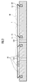
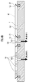
- FIG. 2 is a sectional view taken along line II-II in FIG. 1.
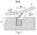
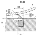
- Configuration explanatory drawing of an annular groove part and an annular rib Configuration explanatory drawing of an annular groove part and an annular rib.
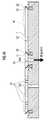
- Explanatory drawing regarding the vacuum suction method of the wafer using a vacuum suction member Explanatory drawing regarding the vacuum suction method of the wafer using a vacuum suction member.
- the vacuum suction member as one embodiment of the present invention shown in FIGS. 1 and 2 includes a base body 1 for sucking and holding a wafer W (substrate) on the upper surface side.
- the substrate 1 is formed of a substantially disk-shaped ceramic sintered body.
- the shape of the substrate 1 may be various shapes such as a polygonal plate shape or an elliptical plate shape in addition to a substantially disk shape.
- the first air passage 101 and the second air passage 102 are formed in the base 1 as a plurality of air passages opened on the upper surface. Each of the first air passage 101 and the second air passage 102 is connected to a common or separate vacuum suction device (not shown).
- the number and position of the openings of the first air passage 101 and the second air passage 102 on the upper surface of the base body 1 are such that the openings of the first air passage 101 are disposed in the inner region of the inner annular groove portion 11 and the second air passage.
- the opening of the path 102 may be arbitrarily changed under the condition that the opening is disposed outside the inner annular groove portion 11 and inside the outer annular groove portion 12.
- Each of the first ventilation path 101 and the second ventilation path 102 is configured by a vertical through-hole of the base body 1, and by a path extending through the inside of the base body 1 or a groove extending on the lower surface (back surface) of the base body 1. It may be configured.
- the base body 1 is bonded to the upper surface of a base (not shown), so that the groove constitutes a part of the ventilation path.
- the base body 1 includes a plurality of convex portions 10 projecting from the upper surface thereof, an inner annular groove portion 11 (auxiliary annular groove portion) recessed in an annular shape from the upper surface at the center portion of the base body 1, and an outer peripheral edge portion of the base body 1 And an outer annular groove 12 that is recessed in an annular shape from the upper surface thereof.
- An annular inner annular rib 21 is fitted in the inner annular groove portion 11.
- An annular outer annular rib 22 is fitted in the outer annular groove portion 12.
- the convex portion 10, the inner annular groove portion 11, the outer annular groove portion 12, the first annular rib 21 and the second annular rib 22 are defaulted to clarify the configuration of the vacuum suction member.
- the ratio between the width or height and the distance between them is different from the actual one.
- the substrate 1 may be formed with a plurality of through holes through which lift pins for adjusting the distance between the upper surface of the substrate 1 and the lower surface of the wafer W are moved up and down (not shown).
- the plurality of convex portions 10 are arranged concentrically around the center of the base body 1 at regular intervals in the circumferential direction and the radial direction.
- the plurality of convex portions 10 are regularly arranged in other forms such as a triangular lattice shape and a square lattice shape, and are locally irregular so that a difference in density is locally produced in the circumferential direction or the radial direction. May be arranged.
- the interval or pitch of the convex portions 10 is designed to be, for example, 8 [mm] or less, preferably 6 [mm], and more preferably 4 [mm] or less.
- the protruding amount of the convex portion 10 from the upper surface of the base body 1 is designed to be included in the range of 50 to 200 [ ⁇ m], for example.
- the convex portion 10 has a columnar shape such as a columnar shape or a prismatic shape, a frustum shape such as a truncated cone shape or a truncated pyramid shape, a columnar shape with a step or a frustum shape such that the upper cross-sectional area is smaller than the lower portion. It is formed into a shape.
- the diameter of the upper end portion (contact portion with the wafer W) of the convex portion 10 is designed to be 500 [ ⁇ m] or less.
- the surface roughness Ra of the upper end portion (contact portion with the wafer W) of the convex portion 10 is designed to be included in the range of 0.01 to 0.50 [ ⁇ m].
- the inner annular groove portion 11 corresponds to a central portion of the wafer W (for example, a region whose distance from the center of the wafer W having a radius R is 0.1R or less, 0.25R or less, or 0.4R or less). It is formed in the position to do.
- the inner annular groove portion 11 surrounds the first air passage 101 and the convex portion 10 existing therearound.
- the outer annular groove 12 is formed at a position corresponding to the outer peripheral edge of the wafer W (for example, a region having a radius R of 0.9 R or more or 0.95 R or more from the center of the wafer W). ing.
- the outer annular groove portion 12 surrounds the second air passage 102 and the convex portion 10 outside the inner annular groove portion 11.
- the shape of the inner annular groove 11 and the outer annular groove 12 in the top view of the substrate 1 can be variously designed according to the shape and size of the inner annular rib 21 and the outer annular rib 22 fitted therein.
- the lower portion of the inner annular rib 21 is accommodated in the inner annular groove portion 11, while the upper portion projects upward from the upper surface of the base 1.
- a lower portion of the outer annular rib 22 is accommodated in the outer annular groove portion 12, while an upper portion thereof projects upward from the upper surface of the base 1.
- Each of the inner annular rib 21 and the outer annular rib 22 is made of an elastic material such as silicon rubber or a sponge-like porous body or a synthetic resin.
- Each of the inner annular rib 21 and the outer annular rib 22 is elastically deformed downward by the load when the wafer W is placed on the upper surface side of the vacuum suction member. It has elasticity to return to its shape.
- the outer annular groove 12 extends in a ring shape having a substantially trapezoidal cross section, and the upper portion of the first groove 121 extends radially outward of the base body 1. And a second groove portion 122 extending annularly.
- the outer annular rib 22 is elastically deformed so that the upper portion 222 is inclined outward with respect to the lower portion 221 by the load of the wafer W, and at least a part of the upper portion 222 is accommodated in the second groove portion 122.
- the root of the upper portion 222 is thinly formed over the entire circumference.
- the outer annular groove 12 extends in an annular shape having a substantially trapezoidal cross-sectional shape, and the upper portion of the first groove 121 extends radially inward of the base body 1. And a second groove portion 122 extending annularly.
- the outer annular rib 22 is elastically deformed so that the upper portion 222 falls inward with respect to the lower portion 221 by the load of the wafer W, and at least a part of the upper portion 222 is accommodated in the second groove portion 122.
- the root of the upper portion 222 is thinly formed over the entire circumference.
- the inner annular groove 11 and the inner annular rib 21 may also be configured in the same manner as shown in FIGS. 3A and 3B.
- the vacuum suction member having the above-described configuration is manufactured by the following procedure, for example. That is, a substantially disk-shaped compact is produced from the raw material powder, and this compact is fired to produce a substantially disk-shaped sintered body.
- the raw material powder for example, silicon carbide having a purity of 97% or more, and mixed raw material powder to which an appropriate amount of a sintering aid is added if necessary are used.
- other ceramic powders such as alumina powder may be used as the raw material powder.
- a plurality of convex portions 10, an inner annular groove portion 11, an outer annular groove portion 12, a first air passage 101, and a second air passage 102 are formed on the sintered body according to an appropriate processing method such as blasting or milling.
- the inner annular rib 21 and the outer annular rib 22 are fitted into the inner annular groove portion 11 and the outer annular groove portion 12, respectively.
- the vacuum suction member 1 having the above-described configuration is manufactured by the above process.
- the outer space S2 surrounded by the upper surface of the substrate 1, the lower surface of the wafer W, the outer surface of the inner annular rib 21, and the inner surface of the outer annular rib 22 is second.
- the posture of the peripheral portion outside the central portion of the wafer W is corrected or maintained flat.
- the wafer W has a relatively large amount of deflection or warpage, it can be adsorbed and held by the vacuum adsorbing member in such a manner that flatness is ensured without any positional deviation.
- the operation timing of the said separate vacuum suction apparatus (or the opening timing of the on-off valve provided in each path
- an opening / closing valve is installed in a connection path between the vacuum suction device and the second air passage 102, and the vacuum suction device By adjusting the operation timing and the opening timing of the on-off valve, the inner space S1 and the outer space S2 are depressurized in order.
- the inner space S ⁇ b> 1 and the outer space S ⁇ b> 2 may be depressurized in order by providing a difference in level of fluid resistance, such as a distance shorter than the path between the upper surface opening of the ventilation path 102.
Landscapes
- Engineering & Computer Science (AREA)
- Mechanical Engineering (AREA)
- Container, Conveyance, Adherence, Positioning, Of Wafer (AREA)
Abstract
撓みまたは反りの程度が大きいウエハの吸着保持時における基板の位置ずれを抑制しうる真空吸着部材および真空吸着方法を提供する。 ウエハWが基体1の上面側に載置された状態で、基体1の上面、ウエハWの下面および内側環状リブ21の内側面により囲まれている内側空間S1が、第1通気路101を通じて減圧される。続いて、基体1の上面、ウエハWの下面、内側環状リブ21の外側面および外側環状リブ22の内側面により囲まれている外側空間S2が、第2通気路102を通じて減圧される。
Description
本発明は、ウエハなどの基板を真空吸着保持するための技術に関する。
基体の外縁に、弾性材料(たとえばゴム)からなり、下から上にかけて徐々に外側に広がるように形成されているスカート状のシール部材が設けられたウエハ加工機の吸着盤構造が提案されている(たとえば、特許文献1参照)。
当該構成の吸着盤構造によれば、ウエハに反り、うねりまたは段差がある場合でも、シール部材の上端部をその全周にわたって当該ウエハに当接させ、ウエハと吸着面との間隙に密閉領域が形成される。このためウエハの反り等によって基体との間に本来的に生じる間隙の影響を解消して、当該密閉領域を負圧として当該ウエハを吸着保持可能としている。
しかし、撓みまたは反りの程度が大きいウエハは、基板が真空吸着部材に搬送された際、当該基板の反りや変形により真空吸着部材とは点当たりまたは面当たりの状態になっており、この状態から真空ポンプ等で吸引を開始すると、前記空間の減圧によって吸着保持された段階で位置ずれを生じる頻度が高かった。
そこで、本発明は、撓みまたは反りの程度が大きいウエハの吸着保持時における位置ずれを抑制しうる真空吸着部材および真空吸着方法を提供することを目的とする。
本発明は、上面から環状に窪んでいる環状溝部が形成され、かつ、前記環状溝部の内側において上面の上方空間に連通する通気路が内部に形成されている基体と、前記基体の上面から上部が環状に突出した状態で前記環状溝部に下部が収容されている、弾性素材からなる環状リブと、を備えている真空吸着部材であって、前記真空吸着部材の上面側に基板が載置されている状態から、前記通気路を通じて前記基体、前記環状リブおよび前記基板により画定される空間が減圧されることにより、前記基板が吸着保持されるものに関する。本発明は、さらに、前記真空吸着部材を用いて、基板を吸着保持する方法に関する。
本発明の真空吸着部材は、前記環状溝部の内側において前記基板の中央部に対応して上面から環状に窪んでいる補助環状溝部が前記基体に形成され、前記通気路の一部が前記補助環状溝部の内側において前記基体の上面の上方空間に連通するように前記基体の内部に形成され、前記基体の上面から上部が環状に突出した状態で前記補助環状溝部に下部が収容されている、弾性素材からなる補助環状リブをさらに備えていることを特徴とする。
本発明の真空吸着方法は、前記環状リブの環状の上端のうち周方向に沿って少なくとも部分的に前記基板の下面が当接するように前記基板を前記真空吸着部材に載置する工程と、前記基板の中央部に対して下方に外力を作用させる工程と、前記通気路を通じて前記基体および前記基板の間の空間を減圧する工程と、を含んでいることを特徴とする。本発明
の真空吸着方法において、本発明の真空吸着部材を前記真空吸着部材として用い、前記通気路の一部を通じて前記補助環状リブの内側における前記基体および前記基板の間の空間を減圧する工程を、前記基板の中央部に対して下方に外力を作用させる工程として含んでいることが好ましい。
の真空吸着方法において、本発明の真空吸着部材を前記真空吸着部材として用い、前記通気路の一部を通じて前記補助環状リブの内側における前記基体および前記基板の間の空間を減圧する工程を、前記基板の中央部に対して下方に外力を作用させる工程として含んでいることが好ましい。
本発明の真空吸着部材によれば、基板が基体の上面側に載置されることにより、環状リブおよび補助環状リブが基板の重みによって弾性変形し、周方向の少なくとも一部において基板の下面に当接する。この状態で、基体の上面、基板の下面および補助環状リブの内側面により囲まれている空間(内側空間)が、一部の通気路を通じて減圧されることにより、基板の中央部分の姿勢が局所的に平坦に矯正かつ維持された状態で基体に固定される。続いて、基体の上面、基板の下面、補助環状リブの外側面および環状リブの内側面により囲まれている空間(外側空間)が、他の通気路を通じて減圧されることにより、基板の中央部分より外側にある周辺部分の姿勢が平坦に矯正かつ維持された状態で基体に固定される。この結果、撓み量または反り量が比較的大きい基板であっても、位置ずれを伴うことなく真空吸着部材に吸着保持されうる。
本発明の真空吸着方法によれば、前記のような内部空間の減圧のほか、基板の中央部に対してその上方から空気の吹き付けまたは治具による押圧などにより下方への外力を作用させた上で、外部空間が減圧されてもよい。この場合も同様に、撓み量または反り量が比較的大きい基板であっても、位置ずれを伴うことなく真空吸着部材に吸着保持されうる。
(構成)
図1および図2に示されている本発明の一実施形態としての真空吸着部材は、ウエハW(基板)を上面側に吸着保持するための基体1を備えている。基体1は、略円板状のセラミックス焼結体により形成されている。基体1の形状は、略円板状のほか、多角形板状または楕円板状などのさまざまな形状であってもよい。
図1および図2に示されている本発明の一実施形態としての真空吸着部材は、ウエハW(基板)を上面側に吸着保持するための基体1を備えている。基体1は、略円板状のセラミックス焼結体により形成されている。基体1の形状は、略円板状のほか、多角形板状または楕円板状などのさまざまな形状であってもよい。
基体1には上面に開口している複数の通気路として第1通気路101および第2通気路102が形成されている。第1通気路101および第2通気路102のそれぞれは共通または別個の真空吸引装置(図示略)に接続されている。
第1通気路101および第2通気路102のそれぞれの基体1の上面における開口の数および位置は、第1通気路101の当該開口が、内側環状溝部11の内側領域に配置され、第2通気路102の当該開口は、内側環状溝部11の外側かつ外側環状溝部12の内側領域に配置されているという条件下で任意に変更されてもよい。第1通気路101および第2通気路102のそれぞれは、基体1の上下方向の貫通孔により構成されるほか、基体1の内部を通る経路または基体1の下面(裏面)に延在する溝により構成されてもよい。基体1の下面に溝が形成されている場合、基体1が基台(図示略)の上面に接合されることにより、当該溝が通気路の一部を構成する。
基体1には、その上面から突出している複数の凸部10と、基体1の中央部においてその上面から円環状に窪んでいる内側環状溝部11(補助環状溝部)と、基体1の外周縁部においてその上面から円環状に窪んでいる外側環状溝部12と、が形成されている。内側環状溝部11には、円環状の内側環状リブ21が嵌装されている。外側環状溝部12には、円環状の外側環状リブ22が嵌装されている。図1および図2では真空吸着部材の構成の明確化のため、凸部10、内側環状溝部11、外側環状溝部12、第1環状リブ21および第2環状リブ22はデフォルトされており、各構成要素の断面図におけるアスペクト比のほか、幅または高さと相互の間隔との比率などは実際とは異なる。
基体1には、ウエハWを昇降させて基体1の上面とウエハWの下面との間隔を調節するためのリフトピンが通る複数の貫通孔が形成されていてもよい(図示略)。
複数の凸部10は、基体1の中心を中心とする同心円状に周方向および径方向に一定の間隔をおいて配置されている。複数の凸部10は、三角格子状、正方格子状などのそのほかの態様で規則的に配置されるほか、周方向または径方向に局所的に疎密の差が生じるように局所的に不規則的に配置されてもよい。凸部10の間隔またはピッチは、例えば8[mm]以下、好ましくは6[mm]、さらに好ましくは4[mm]以下になるように設計されている。凸部10の基体1の上面からの突出量はたとえば50~200[μm]の範囲に含まれるように設計されている。
凸部10は円柱状、角柱状等の柱状のほか、円錐台状、角錐台状等の錘台状、下部よりも上部の断面積が小さくなるような段差付きの柱状または錘台状などの形状に形成される。凸部10の上端部(ウエハWとの当接部分)の径は500[μm]以下となるように設計される。凸部10の上端部(ウエハWとの当接部分)の表面粗さRaは0.01~0.50[μm]の範囲に含まれるように設計されている。
内側環状溝部11は、ウエハWの中央部(例えば、半径RのウエハWの中心からの距離が0.1R以下、0.25R以下、または0.4R以下である領域を意味する。)に対応する位置に形成されている。内側環状溝部11は、第1通気路101およびその周囲に存在する凸部10を取り囲んでいる。外側環状溝部12は、ウエハWの外周縁部(例えば、半径RのウエハWの中心からの距離が0.9R以上または0.95R以上である領域を意味する。)に対応する位置に形成されている。外側環状溝部12は、内側環状溝部11の外側にある第2通気路102および凸部10を取り囲んでいる。
内側環状溝部11および外側環状溝部12のそれぞれの基体1の上面図における形状(図1参照)、基体1の横断面図における形状(図2参照)、(基体1の径方向の)幅および深さは、そこに嵌装される内側環状リブ21および外側環状リブ22のそれぞれの形状およびサイズなどに応じて様々に設計されうる。
内側環状リブ21は、その下部が内側環状溝部11に収容されている一方で、その上部が基体1の上面よりも上方に突出している。外側環状リブ22は、その下部が外側環状溝部12に収容されている一方で、その上部が基体1の上面よりも上方に突出している。
内側環状リブ21および外側環状リブ22のそれぞれは、シリコンゴムまたはスポンジ様の多孔質体などの弾性を有する素材または合成樹脂により構成されている。内側環状リブ21および外側環状リブ22のそれぞれは、ウエハWが真空吸着部材の上面側に載置された際、その荷重によって下方に弾性変形する一方、この荷重から解放された場合には元の形状に戻るような弾性を有している。
図3Aの例によれば、外側環状溝部12が、断面形状が略台形状である環状に延在する第1溝部121と、基体1の径方向外側に第1溝部121の上部を拡張するように環状に延在する第2溝部122と、により構成されている。外側環状リブ22が、第1溝部121に嵌装または嵌合される環状の下部221と、下部221の上端内側領域から全周にわたって外側に傾斜して延在する環状フラップ上の上部222と、により構成されている。ウエハWの荷重によって上部222が下部221に対して外側に倒れるように外側環状リブ22が弾性変形し、少なくとも当該上部222の一部が第2溝部122に収容される。外側環状リブ22のこのような弾性変形を容易にするため、上部222の根元が全周にわたり肉薄に形成されている。
図3Bの例によれば、外側環状溝部12が、断面形状が略台形状である環状に延在する第1溝部121と、基体1の径方向内側に第1溝部121の上部を拡張するように環状に延在する第2溝部122と、により構成されている。外側環状リブ22が、第1溝部121に嵌装または嵌合される環状の下部221と、下部221の上端外側領域から全周にわたって内側に傾斜して延在する環状フラップ上の上部222と、により構成されている。ウエハWの荷重によって上部222が下部221に対して内側に倒れるように外側環状リブ22が弾性変形し、少なくとも当該上部222の一部が第2溝部122に収容される。外側環状リブ22のこのような弾性変形を容易にするため、上部222の根元が全周にわたり肉薄に形成されている。
内側環状溝部11および内側環状リブ21も、図3Aおよび図3Bに示されているのと同様に構成されていてもよい。
(作製方法)
前記構成の真空吸着部材は、たとえば次のような手順で作製される。すなわち、原料粉末から略円板状の成形体が作製され、この成形体が焼成されることで略円板状の焼結体が作製される。原料粉末としては、たとえば純度97%以上の炭化ケイ素、必要に応じてこれに適量の焼結助剤が添加された混合原料粉末が用いられる。そのほか、アルミナ粉末等、他のセラミックス粉末が原料粉末として用いられてもよい。そのうえで、当該焼結体に複数の凸部10、内側環状溝部11、外側環状溝部12、第1通気路101および第2通気路102がブラスト加工またはミリング加工などの適当な加工法にしたがって形成される。そして、内側環状溝部11および外側環状溝部12のそれぞれに対して、内側環状リブ21および外側環状リブ22のそれぞれが嵌装される。前記工程によって前記構成の真空吸着部材1が作製される。
前記構成の真空吸着部材は、たとえば次のような手順で作製される。すなわち、原料粉末から略円板状の成形体が作製され、この成形体が焼成されることで略円板状の焼結体が作製される。原料粉末としては、たとえば純度97%以上の炭化ケイ素、必要に応じてこれに適量の焼結助剤が添加された混合原料粉末が用いられる。そのほか、アルミナ粉末等、他のセラミックス粉末が原料粉末として用いられてもよい。そのうえで、当該焼結体に複数の凸部10、内側環状溝部11、外側環状溝部12、第1通気路101および第2通気路102がブラスト加工またはミリング加工などの適当な加工法にしたがって形成される。そして、内側環状溝部11および外側環状溝部12のそれぞれに対して、内側環状リブ21および外側環状リブ22のそれぞれが嵌装される。前記工程によって前記構成の真空吸着部材1が作製される。
(機能)
前記構成の真空吸着部材によれば、ウエハWが基体1の上面側に載置されることにより、内側環状リブ21(補助環状リブ)および外側環状リブ22がウエハWの重みによって弾性変形し、周方向の少なくとも一部においてウエハWの下面に当接する(図2参照)。
前記構成の真空吸着部材によれば、ウエハWが基体1の上面側に載置されることにより、内側環状リブ21(補助環状リブ)および外側環状リブ22がウエハWの重みによって弾性変形し、周方向の少なくとも一部においてウエハWの下面に当接する(図2参照)。
この状態で、図4Aに示されているように、基体1の上面、ウエハWの下面および内側環状リブ21の内側面により囲まれている内側空間S1が、第1通気路101を通じて減圧されることにより、ウエハWの中央部分の姿勢が局所的に平坦に矯正または維持される。
続いて、図4Bに示されているように、基体1の上面、ウエハWの下面、内側環状リブ21の外側面および外側環状リブ22の内側面により囲まれている外側空間S2が、第2通気路102を通じて減圧されることにより、ウエハWの中央部分より外側にある周辺部分の姿勢が平坦に矯正または維持される。
この結果、撓み量または反り量が比較的大きいウエハWであっても、位置ズレを伴うことなく平坦性が確保されるような形態で真空吸着部材に吸着保持されうる。
なお、第1通気路101および第2通気路102のそれぞれが別個の真空吸引装置により減圧される場合、当該別個の真空吸引装置の動作タイミング(または各経路に設けられた開閉弁の開放タイミング)を調節することにより、内側空間S1および外側空間S2が順に減圧される。第1通気路101および第2通気路102のそれぞれが共通の真空吸引装置により減圧される場合、真空吸引装置と第2通気路102との接続経路に開閉弁が設置され、当該真空吸引装置の動作タイミングと当該開閉弁の開放タイミングとを調節することにより、内側空間S1および外側空間S2が順に減圧される。第1通気路101および第2通気路102のそれぞれが共通の真空吸引装置により減圧される場合、真空吸引装置と第1通気路101の上面開口との間の経路が、真空吸引装置と第2通気路102の上面開口との間の経路よりも距離が短い等、流体抵抗の高低差が設けられることにより、内側空間S1および外側空間S2が順に減圧されてもよい。
1‥基体、10‥凸部、11‥内側環状溝部(補助環状溝部)、12‥外側環状溝部、21‥内側環状リブ(補助環状リブ)、22‥外側環状リブ、101‥第1通気路、102‥第2通気路、W‥ウエハ(基板)。
Claims (3)
- 上面から環状に窪んでいる環状溝部が形成され、かつ、前記環状溝部の内側において上面を通じて外部に連通する通気路が内部に形成されている基体と、
前記基体の上面から上部が環状に突出した状態で前記環状溝部に下部が収容されている、弾性素材からなる環状リブと、を備えている真空吸着部材であって、
前記真空吸着部材の上面側に基板が載置されている状態から、前記通気路を通じて前記基体、前記環状リブおよび前記基板により画定される空間が減圧されることにより、前記基板が吸着保持されるものにおいて、
前記環状溝部の内側において前記基板の中央部に対応して上面から環状に窪んでいる補助環状溝部が前記基体に形成され、
前記通気路の一部が前記補助環状溝部の内側において前記基体の上面の上方空間に連通するように前記基体の内部に形成され、
前記基体の上面から上部が環状に突出した状態で前記補助環状溝部に下部が収容されている、弾性素材からなる補助環状リブをさらに備えていることを特徴とする真空吸着部材。 - 上面から環状に窪んでいる環状溝部が形成され、かつ、前記環状溝部の内側において上面の上方空間に連通する通気路が内部に形成されている基体と、前記環状溝部に下部が収容されている一方、前記基体の上面から上部が環状に突出した状態で前記基体に対して固定されている、弾性素材からなる環状リブと、を備えている真空吸着部材を用いて、基板を吸着保持する方法であって、
前記環状リブの環状の上端のうち周方向に沿って少なくとも部分的に前記基板の下面が当接するように前記基板を前記真空吸着部材に載置する工程と、
前記基板の中央部に対して下方に外力を作用させる工程と、
前記通気路を通じて前記基体および前記基板の間の空間を減圧する工程と、を含んでいることを特徴とする真空吸着方法。 - 請求項2記載の真空吸着方法において、請求項1記載の真空吸着部材を前記真空吸着部材として用い、前記通気路の一部を通じて前記補助環状リブの内側における前記基体および前記基板の間の空間を減圧する工程を、前記基板の中央部に対して下方に外力を作用させる工程として含んでいることを特徴とする真空吸着方法。
Priority Applications (3)
| Application Number | Priority Date | Filing Date | Title |
|---|---|---|---|
| CN201780002572.5A CN107851604B (zh) | 2016-03-09 | 2017-02-06 | 真空吸附构件及真空吸附方法 |
| US15/740,947 US11279005B2 (en) | 2016-03-09 | 2017-02-06 | Vacuum suction member and vacuum suction method |
| KR1020187000590A KR102071149B1 (ko) | 2016-03-09 | 2017-02-06 | 진공흡착부재 및 진공흡착방법 |
Applications Claiming Priority (2)
| Application Number | Priority Date | Filing Date | Title |
|---|---|---|---|
| JP2016-046047 | 2016-03-09 | ||
| JP2016046047A JP6546550B2 (ja) | 2016-03-09 | 2016-03-09 | 真空吸着部材および真空吸着方法 |
Publications (1)
| Publication Number | Publication Date |
|---|---|
| WO2017154436A1 true WO2017154436A1 (ja) | 2017-09-14 |
Family
ID=59789338
Family Applications (1)
| Application Number | Title | Priority Date | Filing Date |
|---|---|---|---|
| PCT/JP2017/004140 Ceased WO2017154436A1 (ja) | 2016-03-09 | 2017-02-06 | 真空吸着部材および真空吸着方法 |
Country Status (6)
| Country | Link |
|---|---|
| US (1) | US11279005B2 (ja) |
| JP (1) | JP6546550B2 (ja) |
| KR (1) | KR102071149B1 (ja) |
| CN (1) | CN107851604B (ja) |
| TW (1) | TWI636500B (ja) |
| WO (1) | WO2017154436A1 (ja) |
Families Citing this family (19)
| Publication number | Priority date | Publication date | Assignee | Title |
|---|---|---|---|---|
| US7812168B2 (en) | 2005-07-05 | 2010-10-12 | Teva Pharmaceutical Industries Ltd. | Purification of montelukast |
| JP2017211604A (ja) * | 2016-05-27 | 2017-11-30 | 株式会社大日本科研 | 基板吸着保持装置および露光装置 |
| MX2019002775A (es) * | 2016-09-09 | 2019-08-29 | Procter & Gamble | Soporte de vacío con junta de falda extensible. |
| US11201079B2 (en) * | 2018-05-30 | 2021-12-14 | Taiwan Semiconductor Manufacturing Company, Ltd. | Wafer chuck |
| JP2020080390A (ja) * | 2018-11-14 | 2020-05-28 | 株式会社ディスコ | チャックテーブル及び加工装置 |
| JP7365800B2 (ja) * | 2019-07-09 | 2023-10-20 | 日清紡マイクロデバイス株式会社 | ステージ装置 |
| US11587818B2 (en) | 2019-07-18 | 2023-02-21 | Taiwan Semiconductor Manufacturing Company, Ltd. | Chuck design and method for wafer |
| US11145535B2 (en) * | 2019-08-15 | 2021-10-12 | Canon Kabushiki Kaisha | Planarization process, apparatus and method of manufacturing an article |
| JP7646628B2 (ja) | 2019-08-20 | 2025-03-17 | エーエスエムエル ネザーランズ ビー.ブイ. | 基板ホルダ、リソグラフィ装置、及び方法 |
| KR102769839B1 (ko) * | 2019-09-09 | 2025-02-20 | 삼성전자주식회사 | 진공 척 및 상기 진공 척을 포함하는 기판 처리 장치 |
| US11791192B2 (en) * | 2020-01-19 | 2023-10-17 | Taiwan Semiconductor Manufacturing Company, Ltd. | Workpiece holder, wafer chuck, wafer holding method |
| CN113140497B (zh) * | 2020-01-19 | 2026-06-05 | 台湾积体电路制造股份有限公司 | 工件把持器、晶片卡盘以及制造半导体封装的方法 |
| US11769673B2 (en) * | 2021-02-15 | 2023-09-26 | Globalfoundries U.S. Inc. | Semiconductor wafer processing system |
| JP7798542B2 (ja) * | 2021-11-22 | 2026-01-14 | 株式会社ディスコ | ウェーハ保持具 |
| KR102413824B1 (ko) * | 2022-01-04 | 2022-06-28 | 주식회사 메이코리아 | 진공압을 이용해 피가공물을 회전 가능하게 고정하는 고정용 지그 |
| JP7839956B2 (ja) * | 2022-03-29 | 2026-04-03 | 株式会社東京精密 | ワーク搬送装置 |
| JP2024016325A (ja) * | 2022-07-26 | 2024-02-07 | ウシオ電機株式会社 | 保持機構及び露光装置 |
| CN115846706B (zh) * | 2022-12-13 | 2023-08-04 | 大连理工大学 | 一种薄壁曲面构件车削加工装夹系统及适应性装夹方法 |
| CN116313980A (zh) * | 2023-03-28 | 2023-06-23 | 合肥芯碁微电子装备股份有限公司 | 晶圆吸附装置 |
Citations (5)
| Publication number | Priority date | Publication date | Assignee | Title |
|---|---|---|---|---|
| JPH03289154A (ja) * | 1990-04-05 | 1991-12-19 | Toshiba Corp | 半導体ウエーハチャック装置 |
| JP2004228453A (ja) * | 2003-01-27 | 2004-08-12 | Renesas Technology Corp | 半導体装置の製造方法 |
| JP2005528794A (ja) * | 2002-05-31 | 2005-09-22 | エイエスエム・ナトゥール・インコーポレーテッド | 全面電気化学めっきのためにウェハの裏側をシールする方法及び装置 |
| JP2007273693A (ja) * | 2006-03-31 | 2007-10-18 | Nikon Corp | 基板保持部材及び基板保持方法、基板保持装置、並びに露光装置及び露光方法 |
| JP2015038982A (ja) * | 2013-07-18 | 2015-02-26 | Nskテクノロジー株式会社 | 基板の保持装置及び密着露光装置並びに近接露光装置 |
Family Cites Families (8)
| Publication number | Priority date | Publication date | Assignee | Title |
|---|---|---|---|---|
| JPH0731245A (ja) * | 1993-07-22 | 1995-02-03 | Nitsukari:Kk | 草刈機 |
| US5634749A (en) * | 1994-03-16 | 1997-06-03 | Jerry Liem | Vacuum vice for bowling balls |
| JPH07308856A (ja) | 1994-05-12 | 1995-11-28 | Tokyo Seimitsu Co Ltd | ウェーハ加工機の吸着盤構造 |
| JP3312163B2 (ja) * | 1994-11-18 | 2002-08-05 | 日本電信電話株式会社 | 真空吸着装置 |
| US6855037B2 (en) | 2001-03-12 | 2005-02-15 | Asm-Nutool, Inc. | Method of sealing wafer backside for full-face electrochemical plating |
| JP5063797B2 (ja) * | 2011-05-23 | 2012-10-31 | 京セラ株式会社 | 吸着部材、吸着装置および吸着方法 |
| JP2013232466A (ja) * | 2012-04-27 | 2013-11-14 | Mitsuboshi Diamond Industrial Co Ltd | 基板吸着装置 |
| US20170053822A1 (en) * | 2015-08-23 | 2017-02-23 | Camtek Ltd. | Warped wafers vacuum chuck |
-
2016
- 2016-03-09 JP JP2016046047A patent/JP6546550B2/ja active Active
-
2017
- 2017-02-06 WO PCT/JP2017/004140 patent/WO2017154436A1/ja not_active Ceased
- 2017-02-06 CN CN201780002572.5A patent/CN107851604B/zh not_active Expired - Fee Related
- 2017-02-06 US US15/740,947 patent/US11279005B2/en active Active
- 2017-02-06 KR KR1020187000590A patent/KR102071149B1/ko not_active Expired - Fee Related
- 2017-03-08 TW TW106107490A patent/TWI636500B/zh active
Patent Citations (5)
| Publication number | Priority date | Publication date | Assignee | Title |
|---|---|---|---|---|
| JPH03289154A (ja) * | 1990-04-05 | 1991-12-19 | Toshiba Corp | 半導体ウエーハチャック装置 |
| JP2005528794A (ja) * | 2002-05-31 | 2005-09-22 | エイエスエム・ナトゥール・インコーポレーテッド | 全面電気化学めっきのためにウェハの裏側をシールする方法及び装置 |
| JP2004228453A (ja) * | 2003-01-27 | 2004-08-12 | Renesas Technology Corp | 半導体装置の製造方法 |
| JP2007273693A (ja) * | 2006-03-31 | 2007-10-18 | Nikon Corp | 基板保持部材及び基板保持方法、基板保持装置、並びに露光装置及び露光方法 |
| JP2015038982A (ja) * | 2013-07-18 | 2015-02-26 | Nskテクノロジー株式会社 | 基板の保持装置及び密着露光装置並びに近接露光装置 |
Also Published As
| Publication number | Publication date |
|---|---|
| JP2017162987A (ja) | 2017-09-14 |
| CN107851604B (zh) | 2021-11-12 |
| TWI636500B (zh) | 2018-09-21 |
| US20180193983A1 (en) | 2018-07-12 |
| CN107851604A (zh) | 2018-03-27 |
| KR20180035786A (ko) | 2018-04-06 |
| KR102071149B1 (ko) | 2020-01-29 |
| JP6546550B2 (ja) | 2019-07-17 |
| TW201735149A (zh) | 2017-10-01 |
| US11279005B2 (en) | 2022-03-22 |
Similar Documents
| Publication | Publication Date | Title |
|---|---|---|
| JP6546550B2 (ja) | 真空吸着部材および真空吸着方法 | |
| TWI690017B (zh) | 基板保持裝置 | |
| JPWO2017086333A1 (ja) | 真空チャック | |
| JP2017220483A (ja) | 真空チャック及び真空チャックの製造方法 | |
| JP6496255B2 (ja) | 基板保持装置 | |
| KR102052878B1 (ko) | 화학 기계적 연마 장치의 캐리어 헤드 및 이에 사용되는 멤브레인 | |
| KR102071123B1 (ko) | 기판유지장치, 기판유지부재 및 기판유지방법 | |
| JP6894772B2 (ja) | 真空チャック | |
| JP6325933B2 (ja) | 真空チャック | |
| JP6680649B2 (ja) | 真空吸着部材 | |
| JP7021969B2 (ja) | 真空吸着部材および真空吸着方法 | |
| JP6789006B2 (ja) | 真空吸着装置 | |
| JP6711721B2 (ja) | 真空吸着部材 | |
| JP2017199790A (ja) | 真空吸着部材 | |
| JP6581495B2 (ja) | 基板保持装置 | |
| JP6867226B2 (ja) | 真空吸着部材 | |
| JP7178831B2 (ja) | 基板保持部材 | |
| JP6704839B2 (ja) | 真空吸着部材 | |
| JP2021141212A (ja) | 基板保持装置 | |
| JP7190326B2 (ja) | 基板保持部材 | |
| JP7260984B2 (ja) | 基板保持部材 | |
| KR20240051058A (ko) | 기판 유지 부재 | |
| JP2023098194A (ja) | 基板保持部材 |
Legal Events
| Date | Code | Title | Description |
|---|---|---|---|
| ENP | Entry into the national phase |
Ref document number: 20187000590 Country of ref document: KR Kind code of ref document: A |
|
| NENP | Non-entry into the national phase |
Ref country code: DE |
|
| 121 | Ep: the epo has been informed by wipo that ep was designated in this application |
Ref document number: 17762780 Country of ref document: EP Kind code of ref document: A1 |
|
| 122 | Ep: pct application non-entry in european phase |
Ref document number: 17762780 Country of ref document: EP Kind code of ref document: A1 |