WO2017154164A1 - ガイドワイヤ - Google Patents
ガイドワイヤ Download PDFInfo
- Publication number
- WO2017154164A1 WO2017154164A1 PCT/JP2016/057539 JP2016057539W WO2017154164A1 WO 2017154164 A1 WO2017154164 A1 WO 2017154164A1 JP 2016057539 W JP2016057539 W JP 2016057539W WO 2017154164 A1 WO2017154164 A1 WO 2017154164A1
- Authority
- WO
- WIPO (PCT)
- Prior art keywords
- guide wire
- coil body
- tip
- core shaft
- longitudinal direction
- Prior art date
Links
Images


Classifications
-
- A—HUMAN NECESSITIES
- A61—MEDICAL OR VETERINARY SCIENCE; HYGIENE
- A61M—DEVICES FOR INTRODUCING MEDIA INTO, OR ONTO, THE BODY; DEVICES FOR TRANSDUCING BODY MEDIA OR FOR TAKING MEDIA FROM THE BODY; DEVICES FOR PRODUCING OR ENDING SLEEP OR STUPOR
- A61M25/00—Catheters; Hollow probes
- A61M25/01—Introducing, guiding, advancing, emplacing or holding catheters
- A61M25/09—Guide wires
-
- A—HUMAN NECESSITIES
- A61—MEDICAL OR VETERINARY SCIENCE; HYGIENE
- A61B—DIAGNOSIS; SURGERY; IDENTIFICATION
- A61B17/00—Surgical instruments, devices or methods, e.g. tourniquets
- A61B17/12—Surgical instruments, devices or methods, e.g. tourniquets for ligaturing or otherwise compressing tubular parts of the body, e.g. blood vessels, umbilical cord
- A61B17/12022—Occluding by internal devices, e.g. balloons or releasable wires
- A61B17/12099—Occluding by internal devices, e.g. balloons or releasable wires characterised by the location of the occluder
- A61B17/12109—Occluding by internal devices, e.g. balloons or releasable wires characterised by the location of the occluder in a blood vessel
- A61B17/12113—Occluding by internal devices, e.g. balloons or releasable wires characterised by the location of the occluder in a blood vessel within an aneurysm
-
- A—HUMAN NECESSITIES
- A61—MEDICAL OR VETERINARY SCIENCE; HYGIENE
- A61B—DIAGNOSIS; SURGERY; IDENTIFICATION
- A61B17/00—Surgical instruments, devices or methods, e.g. tourniquets
- A61B17/12—Surgical instruments, devices or methods, e.g. tourniquets for ligaturing or otherwise compressing tubular parts of the body, e.g. blood vessels, umbilical cord
- A61B17/12022—Occluding by internal devices, e.g. balloons or releasable wires
- A61B2017/1205—Introduction devices
-
- A—HUMAN NECESSITIES
- A61—MEDICAL OR VETERINARY SCIENCE; HYGIENE
- A61M—DEVICES FOR INTRODUCING MEDIA INTO, OR ONTO, THE BODY; DEVICES FOR TRANSDUCING BODY MEDIA OR FOR TAKING MEDIA FROM THE BODY; DEVICES FOR PRODUCING OR ENDING SLEEP OR STUPOR
- A61M25/00—Catheters; Hollow probes
- A61M25/01—Introducing, guiding, advancing, emplacing or holding catheters
- A61M25/09—Guide wires
- A61M2025/09058—Basic structures of guide wires
- A61M2025/09083—Basic structures of guide wires having a coil around a core
-
- A—HUMAN NECESSITIES
- A61—MEDICAL OR VETERINARY SCIENCE; HYGIENE
- A61M—DEVICES FOR INTRODUCING MEDIA INTO, OR ONTO, THE BODY; DEVICES FOR TRANSDUCING BODY MEDIA OR FOR TAKING MEDIA FROM THE BODY; DEVICES FOR PRODUCING OR ENDING SLEEP OR STUPOR
- A61M25/00—Catheters; Hollow probes
- A61M25/01—Introducing, guiding, advancing, emplacing or holding catheters
- A61M25/09—Guide wires
- A61M2025/09175—Guide wires having specific characteristics at the distal tip
-
- A—HUMAN NECESSITIES
- A61—MEDICAL OR VETERINARY SCIENCE; HYGIENE
- A61M—DEVICES FOR INTRODUCING MEDIA INTO, OR ONTO, THE BODY; DEVICES FOR TRANSDUCING BODY MEDIA OR FOR TAKING MEDIA FROM THE BODY; DEVICES FOR PRODUCING OR ENDING SLEEP OR STUPOR
- A61M25/00—Catheters; Hollow probes
- A61M25/01—Introducing, guiding, advancing, emplacing or holding catheters
- A61M25/09—Guide wires
- A61M2025/09191—Guide wires made of twisted wires
Definitions
- the present invention relates to a guide wire used as a guide when inserting a catheter into a body lumen such as a blood vessel or a ureter and inserting an indwelling device into an aneurysm forming portion of the blood vessel.
- a guide wire used as a guide when inserting a catheter into a body lumen such as a blood vessel or a ureter and inserting an indwelling device into a blood vessel aneurysm formation part generally includes a core shaft and the core shaft.
- tip of a coil body, and the base end junction part which joins a core shaft and the base end of a coil body are provided.
- Patent Document 1 includes a core wire (hereinafter referred to as a core shaft), a coil body that covers the tip portion of the core shaft, and a tip joint portion that joins the tip of the core shaft and the tip of the coil body.
- the guide wire is described, and the appearance in which the tip joint is joined to the tip of the coil body is described (see FIG. 12A, FIG. 12B, etc.).
- the operator inserts the guide wire described in Patent Document 1 into the patient's body and advances it toward the stenosis portion or the like in the patient's body, and then the stenosis. The part is penetrated.
- the guide wire may be stacked on the narrowed portion. At that time, the operator tries to release the guide wire from the stacked state by pushing and pulling the connector fixed to the proximal end portion of the guide wire or rotating the connector.
- the present invention has been made in order to solve the above-described problems, and has improved the bonding strength between the tip joint portion of the guide wire and the coil body, and prevents the tip joint portion from being detached from the coil body.
- the object is to provide a wire.
- a first aspect of the present invention includes a core shaft, a coil body that covers an outer periphery of the core shaft, and a joint portion that joins the tip of the core shaft and the tip of the coil body.
- the base end of the said junction part is formed in the uneven
- the second aspect of the present invention is characterized in that, in the first aspect of the invention, the convex portion protruding toward the front end side in the longitudinal direction is formed in a curved shape.
- the coil body is formed by spirally winding a plurality of stranded wires obtained by twisting a plurality of strands. It is characterized by being.
- the guide wire of the first aspect of the present invention it is provided with a core shaft, a coil body that covers the outer periphery of the core shaft, and a joint portion that joins the tip of the core shaft and the tip of the coil body. Since the base end of this is formed in a longitudinal concavo-convex shape along the outer peripheral direction in the cross-sectional view, it has the effect of improving the joint strength between the joint portion and the coil body and preventing the joint portion from coming off the coil body. Play.
- the convex portion protruding toward the distal end side in the longitudinal direction is formed in a curved shape.
- the coil body in the guide wire of the first aspect or the guide wire of the second aspect, has a plurality of stranded wires formed by twisting a plurality of strands in a spiral shape. Since it is formed by winding, the effect of the guide wire of the first aspect or the guide wire of the second aspect can be achieved more easily.
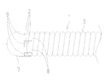
- FIG. 1 is an overall view of a guide wire according to a first embodiment of the present invention. It is a front-end
- FIG. 1 is an overall view of a guide wire according to a first embodiment of the present invention
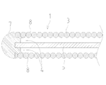
- FIG. 2 is an enlarged view of the distal end of FIG. 1
- FIG. 3 is a longitudinal sectional view of FIG.
- a guide wire 1 includes a core shaft 5, a coil body 3 fixed to the tip of the core shaft 5, and a tip joint 7 that joins the tip of the coil body 3 and the tip of the core shaft 5. And a base end joint portion 6 that joins the base end of the coil body 3 and the core shaft 5.
- the core shaft 5 has a round bar shape that tapers from the proximal end toward the distal end side.
- the material of the core shaft 5 is not particularly limited, but in this embodiment, stainless steel is used, and other superelastic alloys such as Ni—Ti alloys can also be used.
- the coil body 3 is spirally wound around the core shaft 5 and has a hollow cylindrical shape.
- the material of the coil body 3 is not particularly limited, but in this embodiment, stainless steel is used, and tungsten can also be used.
- the coil body 3 in this embodiment is formed with one metal strand, and has a relatively large twist angle with respect to the longitudinal direction of the guide wire 1.
- the distal joint 7 constitutes the distal end of the guide wire 1 and has a substantially hemispherical shape.
- the outer diameter of the proximal end of the distal joint 7 is substantially the same as the outer diameter of the coil body 3.
- the material of the tip joint 7 is not particularly limited, but in this embodiment, an Ag—Sn brazing material is used, and other Au—Sn brazing materials can also be used.
- the distal end joint portion 7 has a base end shape including a rectangular convex portion 8 protruding toward the longitudinal base end side of the guide wire 1 and a rectangular concave portion 9 protruding toward the longitudinal end side. It has become. That is, when the front end joint portion 7 is viewed in a cross section when the front end joint portion 7 is cut in a direction perpendicular to the paper surface of FIG. (Corresponding to “cross-sectional view” of the present invention), the length of the guide wire 1 in the longitudinal direction is different along the outer peripheral direction of the cross section, and the rectangular convex portion 8 protrudes toward the base end side in the longitudinal direction. And the concave-convex shape in the longitudinal direction is formed by the rectangular concave portion 9 protruding to the front end side in the longitudinal direction.
- the proximal end joint portion 6 has an outer diameter at the distal end substantially the same as the outer diameter of the coil body 3.
- the material of the proximal end joint portion 6 is not particularly limited, but in this embodiment, an Ag—Sn brazing material is used, and other Au—Sn brazing materials can also be used. .
- the proximal end of the distal end joint portion 7 is formed in a concave-convex shape in the longitudinal direction along the outer circumferential direction in the cross-sectional view, whereby the coil body 3 when the guide wire 1 is curved is formed.
- the distortion can be alleviated by the gap 2 formed by the rectangular convex portion 8 projecting to the longitudinal base end side and the rectangular concave portion 9 projecting to the distal end side in the longitudinal direction. It is possible to improve the bonding strength between the front end joint portion 7 and the coil body 3 and to prevent the front end joint portion 7 from being detached from the coil body 3.
- the end of the rectangular convex portion 8 protruding toward the base end side in the longitudinal direction does not follow the strand of the coil body 3, but the end of the convex portion 8 is the strand of the coil body 3. If the lengths of the convex portions 8 are made different from each other, the joint strength between the tip joint portion 7 and the coil body 3 can be further improved.
- the distortion of the coil body 3 when the guide wire 1 is curved is caused by the rectangular convex portion 8 projecting toward the longitudinal base end side.
- the clearance 4 formed by the core shaft 5 can also alleviate, and as a result, the bonding strength between the tip joint 7 and the coil body 3 is improved, and the tip joint 7 is detached from the coil body 3. Can be prevented.
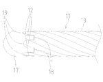
- FIG. 4 is an enlarged view of the distal end of the guide wire according to the second embodiment
- FIG. 5 is a longitudinal sectional view of FIG.
- the guide wire 11 includes a core shaft 5, a coil body 13 fixed to the tip of the core shaft 5, and a tip joint 17 that joins the tip of the coil body 13 and the tip of the core shaft 5. And.
- the coil body 13 is spirally wound around the core shaft 5 and has a hollow cylindrical shape.
- the material of the coil body 13 is not specifically limited, In this embodiment, stainless steel is used and other tungsten can also be used.
- the coil body 13 in the present embodiment is formed by twisting a plurality of (10 in the present embodiment) metal strands into a hollow cylindrical shape, and the twist angle with respect to the major axis direction of the guide wire is relatively small. It is in a state.
- the tip joint portion 17 constitutes the tip of the guide wire 11 and has a substantially hemispherical shape.
- the material of the tip joint portion 17 is not particularly limited, but in the present embodiment, an Au—Sn brazing material is used, and other Au—Sn brazing materials can also be used.
- the distal end joint portion 17 has a base end shape that has a rectangular convex portion 18 that protrudes toward the proximal end side in the longitudinal direction of the guide wire 11 and a curved recess portion 19 that protrudes toward the distal end side in the longitudinal direction. It has become. That is, when the front end joint portion 17 is viewed in a cross section when the front end joint portion 17 is cut in a direction perpendicular to the paper surface of FIG. 4 (cut in a direction perpendicular to the longitudinal direction of the guide wire 11).
- the length of the guide wire 11 in the longitudinal direction is different along the outer peripheral direction of the cross-section, and the rectangular convex portion 8 protrudes toward the base end side in the longitudinal direction.
- the concave-convex shape 19 in the longitudinal direction is formed by the curved concave portion 19 protruding toward the front end side in the longitudinal direction.
- the proximal end of the distal end joint portion 17 is formed in a concave-convex shape in the longitudinal direction along the outer peripheral direction in the cross-sectional view, whereby the coil body 13 when the guide wire 11 is curved is formed.
- the distortion can be alleviated by a gap 12 formed by a rectangular convex portion 18 projecting to the longitudinal base end side and a curved concave portion 19 projecting to the distal end side in the longitudinal direction, and the guide wire 11 is curved. In this case, it is possible to prevent stress concentration on the tip joint portion 17 and further prevent the tip joint portion 17 from detaching from the coil body 13.
- the distortion of the coil body 13 when the guide wire 11 is curved is caused by the rectangular convex portion 18 projecting toward the proximal end side in the longitudinal direction.
- the clearance 14 formed by the core shaft 5 can also alleviate, and as a result, the joint strength between the tip joint 17 and the coil body 13 is improved, and the tip joint 17 is detached from the coil body 13. Can be prevented.
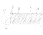
- FIG. 6 is an enlarged view of the distal end of the guide wire according to the third embodiment
- FIG. 7 is a longitudinal sectional view of FIG.
- the guide wire 21 includes a core shaft 5, a coil body 23 fixed to the tip portion of the core shaft 5, and a tip joint portion 27 that joins the tip of the coil body 23 and the tip of the core shaft 5. And.
- the coil body 23 is spirally wound around the core shaft 5 and has a hollow cylindrical shape.
- the material of the coil body 23 is not particularly limited, but in the present embodiment, stainless steel is used, and tungsten can also be used.
- the coil body 23 in the present embodiment is formed by spirally winding 10 strands 25 formed by twisting seven metal strands (see FIG. 7) around the core shaft 5. It has been done.
- the tip joint 27 constitutes the tip of the guide wire 21 and has a substantially hemispherical shape.
- the material of the tip joint portion 27 is not particularly limited, but in this embodiment, an Ag—Sn brazing material is used, and other Au—Sn brazing materials can also be used.
- the distal end joint portion 27 has a wedge-shaped convex portion 28 projecting toward the longitudinal proximal end side of the guide wire 21 and a rectangular concave portion 29 projecting toward the longitudinal distal end side. It has become. That is, when the front end joint portion 27 is viewed in a cross section when the front end joint portion 27 is cut in a direction perpendicular to the paper surface of FIG. 6 (cut in a direction perpendicular to the longitudinal direction of the guide wire 21). (Corresponding to “cross-sectional view” of the present invention), the length of the guide wire 21 in the longitudinal direction is different along the outer peripheral direction of the cross section, and the wedge-shaped convex portion 28 protruding toward the proximal end side in the longitudinal direction. And the concave-convex shape in the longitudinal direction is formed by the rectangular concave portion 29 protruding to the front end side in the longitudinal direction.
- the proximal end of the distal end joint portion 27 is formed in a concave-convex shape in the longitudinal direction along the outer peripheral direction in the cross-sectional view, whereby the coil body 23 when the guide wire 21 is curved is formed.
- the distortion can be alleviated by a gap 22 formed by a wedge-shaped convex portion 28 projecting toward the proximal end side in the longitudinal direction and a rectangular concave portion 29 projecting toward the distal end side in the longitudinal direction.
- the constituent brazing material is infiltrated between the metal strands constituting the stranded wire 25 to improve the joining strength between the tip joint portion 27 of the guide wire 21 and the coil body 23, and the tip joint portion 27 is removed from the coil body 23. It is possible to further prevent separation.
- the distortion of the coil body 23 when the guide wire 21 is bent is caused by the wedge-shaped convex portion 28 protruding to the proximal end side in the longitudinal direction.
- the clearance 24 formed by the core shaft 5 can also alleviate, and as a result, the joining strength between the tip joint 27 and the coil body 23 is improved, and the tip joint 27 is detached from the coil body 23. Can be prevented.
- FIG. 8 is an overall view of the guide wire of the fourth embodiment
- FIG. 9 is an enlarged view of the tip of FIG.
- the longitudinal cross-sectional view in this embodiment is the same as that of FIG. 7, it abbreviate
- the guide wire 31 includes a core shaft 5, a coil body 33 fixed to the tip portion of the core shaft 5, and a tip joint portion 37 that joins the tip of the coil body 33 and the tip of the core shaft 5. And a base end joint portion 36 that joins the base end of the coil body 33 and the core shaft 5.
- the coil body 33 is spirally wound around the core shaft 5 and has a hollow cylindrical shape.
- the material of the coil body 33 is not particularly limited, but in this embodiment, stainless steel is used, and tungsten can also be used.
- the coil body 33 in this embodiment is the same as the coil body 23 of 3rd Embodiment, 10 twisted wires 35 formed by twisting seven metal strands around the core shaft 5. It is formed by spirally winding.
- the tip joint portion 37 constitutes the tip of the guide wire 31 and has a substantially hemispherical shape.
- the material of the tip joint portion 37 is not particularly limited, but in this embodiment, an Ag—Sn brazing material is used, and other Au—Sn brazing materials can be used.
- the distal end joint portion 37 has a wedge-shaped convex portion 38 projecting toward the proximal end side in the longitudinal direction of the guide wire 31 and a curved concave portion 39 projecting toward the distal end side in the longitudinal direction. It has become. That is, when the tip joint portion 37 is viewed in a cross section when the tip joint portion 37 is cut in a direction perpendicular to the paper surface of FIG. 9 (cut in a direction perpendicular to the longitudinal direction of the guide wire 31).
- the length of the guide wire 31 in the longitudinal direction is different along the outer peripheral direction of the cross section, and the wedge-shaped convex portion 38 that protrudes toward the proximal end side in the longitudinal direction
- the concave-convex shape 39 in the longitudinal direction is formed by the curved concave portion 39 protruding toward the front end side in the longitudinal direction.
- the proximal end joint portion 36 has an outer diameter at the distal end substantially the same as the outer diameter of the coil body 33.
- the material of the proximal end joint 36 is not particularly limited, but in this embodiment, an Ag—Sn brazing material is used, and other Au—Sn brazing materials can also be used. .
- the proximal end of the distal end joint portion 37 is formed in a concave-convex shape in the longitudinal direction along the outer peripheral direction in the cross-sectional view, so that the coil body 33 when the guide wire 31 is curved
- the distortion can be alleviated by the gap 32 formed by the wedge-shaped convex portion 38 projecting toward the longitudinal base end side and the curved concave portion 39 projecting toward the distal end side in the longitudinal direction.
- the brazing material constituting the tip joint portion 37 is infiltrated between the metal strands constituting the stranded wire 35 to further improve the joint strength between the tip joint portion 37 of the guide wire 31 and the coil body 33, and
- the curved concave portion 39 can prevent stress concentration on the tip joint portion 37 when the guide wire 31 is curved, and further prevent the tip joint portion 37 from being detached from the coil body 33.
- the coil body is formed from a metal strand, but may be formed from a resin strand.
- the tip joint portion is made of a brazing material, it is more convenient to form it from a metal wire because of the joining relationship.
- the tip joint portion is made of Ag—Sn brazing material or Au—Sn brazing material.
- the core shaft and the coil body may be fixed using an adhesive.
- the bonding strength of the Ag—Sn brazing material or the Au—Sn brazing material is better.
Priority Applications (7)
| Application Number | Priority Date | Filing Date | Title |
|---|---|---|---|
| EP16829222.5A EP3248644B1 (de) | 2016-03-10 | 2016-03-10 | Führungsdraht |
| JP2016563866A JP6233997B1 (ja) | 2016-03-10 | 2016-03-10 | ガイドワイヤ |
| PCT/JP2016/057539 WO2017154164A1 (ja) | 2016-03-10 | 2016-03-10 | ガイドワイヤ |
| KR1020177001925A KR102137302B1 (ko) | 2016-03-10 | 2016-03-10 | 가이드 와이어 |
| CN202110471608.2A CN113181513B (zh) | 2016-03-10 | 2016-03-10 | 导丝 |
| CN201680001588.XA CN107683161B (zh) | 2016-03-10 | 2016-03-10 | 导丝 |
| US15/441,634 US10493245B2 (en) | 2016-03-10 | 2017-02-24 | Guide wire |
Applications Claiming Priority (1)
| Application Number | Priority Date | Filing Date | Title |
|---|---|---|---|
| PCT/JP2016/057539 WO2017154164A1 (ja) | 2016-03-10 | 2016-03-10 | ガイドワイヤ |
Related Child Applications (1)
| Application Number | Title | Priority Date | Filing Date |
|---|---|---|---|
| US15/441,634 Continuation US10493245B2 (en) | 2016-03-10 | 2017-02-24 | Guide wire |
Publications (1)
| Publication Number | Publication Date |
|---|---|
| WO2017154164A1 true WO2017154164A1 (ja) | 2017-09-14 |
Family
ID=59787974
Family Applications (1)
| Application Number | Title | Priority Date | Filing Date |
|---|---|---|---|
| PCT/JP2016/057539 WO2017154164A1 (ja) | 2016-03-10 | 2016-03-10 | ガイドワイヤ |
Country Status (6)
| Country | Link |
|---|---|
| US (1) | US10493245B2 (de) |
| EP (1) | EP3248644B1 (de) |
| JP (1) | JP6233997B1 (de) |
| KR (1) | KR102137302B1 (de) |
| CN (2) | CN113181513B (de) |
| WO (1) | WO2017154164A1 (de) |
Cited By (1)
| Publication number | Priority date | Publication date | Assignee | Title |
|---|---|---|---|---|
| WO2022113233A1 (ja) * | 2020-11-26 | 2022-06-02 | 朝日インテック株式会社 | ガイドワイヤ |
Families Citing this family (4)
| Publication number | Priority date | Publication date | Assignee | Title |
|---|---|---|---|---|
| JP6906104B2 (ja) * | 2018-05-09 | 2021-07-21 | 朝日インテック株式会社 | 医療用チューブ |
| WO2020003501A1 (ja) * | 2018-06-29 | 2020-01-02 | 朝日インテック株式会社 | ガイドワイヤ |
| WO2020261542A1 (ja) * | 2019-06-28 | 2020-12-30 | 朝日インテック株式会社 | ガイドワイヤ |
| JP6994287B2 (ja) | 2020-02-27 | 2022-01-14 | 朝日インテック株式会社 | ガイドワイヤ |
Citations (2)
| Publication number | Priority date | Publication date | Assignee | Title |
|---|---|---|---|---|
| US20070185415A1 (en) | 2005-07-07 | 2007-08-09 | Ressemann Thomas V | Steerable guide wire with torsionally stable tip |
| JP2015171519A (ja) * | 2014-02-24 | 2015-10-01 | 朝日インテック株式会社 | ガイドワイヤ |
Family Cites Families (36)
| Publication number | Priority date | Publication date | Assignee | Title |
|---|---|---|---|---|
| US3973556A (en) * | 1975-06-20 | 1976-08-10 | Lake Region Manufacturing Company, Inc. | Smoothened coil spring wire guide |
| US4456017A (en) * | 1982-11-22 | 1984-06-26 | Cordis Corporation | Coil spring guide with deflectable tip |
| US4721117A (en) * | 1986-04-25 | 1988-01-26 | Advanced Cardiovascular Systems, Inc. | Torsionally stabilized guide wire with outer jacket |
| US6251086B1 (en) * | 1999-07-27 | 2001-06-26 | Scimed Life Systems, Inc. | Guide wire with hydrophilically coated tip |
| US6306105B1 (en) * | 1998-05-14 | 2001-10-23 | Scimed Life Systems, Inc. | High performance coil wire |
| US20040082879A1 (en) * | 2000-01-28 | 2004-04-29 | Klint Henrik S. | Endovascular medical device with plurality of wires |
| US6638267B1 (en) * | 2000-12-01 | 2003-10-28 | Advanced Cardiovascular Systems, Inc. | Guidewire with hypotube and internal insert |
| US6881194B2 (en) * | 2001-03-21 | 2005-04-19 | Asahi Intec Co., Ltd. | Wire-stranded medical hollow tube, and a medical guide wire |
| JP2002275774A (ja) * | 2001-03-21 | 2002-09-25 | Asahi Intecc Co Ltd | 医療用チューブ体、バルーンカテーテルおよび医療用ガイドワイヤ |
| US7532920B1 (en) * | 2001-05-31 | 2009-05-12 | Advanced Cardiovascular Systems, Inc. | Guidewire with optical fiber |
| US7025734B1 (en) * | 2001-09-28 | 2006-04-11 | Advanced Cardiovascular Systmes, Inc. | Guidewire with chemical sensing capabilities |
| DE60216563T2 (de) * | 2001-10-25 | 2007-12-13 | Nipro Corp., Osaka | Führungsdraht |
| US7169118B2 (en) * | 2003-02-26 | 2007-01-30 | Scimed Life Systems, Inc. | Elongate medical device with distal cap |
| ATE495782T1 (de) * | 2004-03-26 | 2011-02-15 | Lake Region Medical R & D Ltd | Medizinischer führungsdraht mit distalen kante |
| US8702626B1 (en) * | 2004-04-21 | 2014-04-22 | Acclarent, Inc. | Guidewires for performing image guided procedures |
| US9974930B2 (en) * | 2005-03-24 | 2018-05-22 | Brivant Research & Development Limited | Guide wire for use in re-canalising a vascular occlusion in a human or animal subject |
| US8043232B2 (en) * | 2005-08-05 | 2011-10-25 | Cook Medical Technologies Llc | High performance wire guide |
| JP5441336B2 (ja) * | 2007-05-11 | 2014-03-12 | テルモ株式会社 | ガイドワイヤ |
| US9095685B2 (en) * | 2008-01-23 | 2015-08-04 | Mediguide Ltd. | Sensor mounted flexible guidewire |
| JP4889062B2 (ja) * | 2010-02-19 | 2012-02-29 | 朝日インテック株式会社 | ガイドワイヤ |
| JP5240948B2 (ja) * | 2010-08-02 | 2013-07-17 | 朝日インテック株式会社 | ガイドワイヤ |
| JP5273820B2 (ja) * | 2010-08-10 | 2013-08-28 | 朝日インテック株式会社 | ガイドワイヤ |
| JP5448200B2 (ja) * | 2011-03-01 | 2014-03-19 | 朝日インテック株式会社 | ガイドワイヤ |
| JP2012200290A (ja) * | 2011-03-23 | 2012-10-22 | Asahi Intecc Co Ltd | ガイドワイヤ |
| JP2014236757A (ja) * | 2011-09-29 | 2014-12-18 | テルモ・クリニカルサプライ株式会社 | ガイドワイヤ |
| JP2013094343A (ja) * | 2011-10-31 | 2013-05-20 | Asahi Intecc Co Ltd | ガイドワイヤ |
| JP2015506777A (ja) * | 2012-02-12 | 2015-03-05 | カーディオサート エルティーディー. | 心血管病変に使用するためのガイドワイヤー |
| US8574170B2 (en) * | 2012-04-06 | 2013-11-05 | Covidien Lp | Guidewire |
| US9138566B2 (en) * | 2012-05-13 | 2015-09-22 | Bendit Technologies Ltd. | Steering tool |
| JP2014161705A (ja) * | 2013-02-28 | 2014-09-08 | Asahi Intecc Co Ltd | ガイドワイヤ |
| JP5448125B1 (ja) * | 2013-05-31 | 2014-03-19 | 株式会社エフエムディ | 医療用ガイドワイヤ |
| JP6482766B2 (ja) * | 2014-03-19 | 2019-03-13 | 朝日インテック株式会社 | ガイドワイヤ |
| JP5875200B2 (ja) * | 2014-10-14 | 2016-03-02 | 朝日インテック株式会社 | ガイドワイヤ |
| CA2983341A1 (en) * | 2015-05-06 | 2016-11-10 | Rotation Medical, Inc. | Medical implant delivery system and related methods |
| EP3294160B1 (de) * | 2015-05-14 | 2022-04-20 | Cook Medical Technologies, LLC | Endoskopischer nadelführungsstab mit längen mit erhöhter flexibilität |
| JP6813243B2 (ja) * | 2016-05-27 | 2021-01-13 | 朝日インテック株式会社 | ガイドワイヤ |
-
2016
- 2016-03-10 CN CN202110471608.2A patent/CN113181513B/zh active Active
- 2016-03-10 KR KR1020177001925A patent/KR102137302B1/ko active IP Right Grant
- 2016-03-10 JP JP2016563866A patent/JP6233997B1/ja active Active
- 2016-03-10 CN CN201680001588.XA patent/CN107683161B/zh active Active
- 2016-03-10 EP EP16829222.5A patent/EP3248644B1/de active Active
- 2016-03-10 WO PCT/JP2016/057539 patent/WO2017154164A1/ja active Application Filing
-
2017
- 2017-02-24 US US15/441,634 patent/US10493245B2/en active Active
Patent Citations (2)
| Publication number | Priority date | Publication date | Assignee | Title |
|---|---|---|---|---|
| US20070185415A1 (en) | 2005-07-07 | 2007-08-09 | Ressemann Thomas V | Steerable guide wire with torsionally stable tip |
| JP2015171519A (ja) * | 2014-02-24 | 2015-10-01 | 朝日インテック株式会社 | ガイドワイヤ |
Non-Patent Citations (1)
| Title |
|---|
| See also references of EP3248644A4 |
Cited By (1)
| Publication number | Priority date | Publication date | Assignee | Title |
|---|---|---|---|---|
| WO2022113233A1 (ja) * | 2020-11-26 | 2022-06-02 | 朝日インテック株式会社 | ガイドワイヤ |
Also Published As
| Publication number | Publication date |
|---|---|
| JP6233997B1 (ja) | 2017-11-22 |
| CN113181513B (zh) | 2023-05-12 |
| US10493245B2 (en) | 2019-12-03 |
| KR20170134305A (ko) | 2017-12-06 |
| US20170259040A1 (en) | 2017-09-14 |
| KR102137302B1 (ko) | 2020-07-23 |
| EP3248644A1 (de) | 2017-11-29 |
| EP3248644B1 (de) | 2020-08-12 |
| CN113181513A (zh) | 2021-07-30 |
| CN107683161B (zh) | 2021-04-27 |
| CN107683161A (zh) | 2018-02-09 |
| EP3248644A4 (de) | 2018-05-02 |
| JPWO2017154164A1 (ja) | 2018-03-22 |
Similar Documents
| Publication | Publication Date | Title |
|---|---|---|
| JP6233997B1 (ja) | ガイドワイヤ | |
| JP2008161491A (ja) | 医療用ガイドワイヤ | |
| JP2009000337A (ja) | 医療用ガイドワイヤ | |
| JP5240948B2 (ja) | ガイドワイヤ | |
| EP3072549A1 (de) | Katheter | |
| JP7162957B2 (ja) | カテーテル | |
| EP2921195A1 (de) | Führungsdraht | |
| JP2021178226A (ja) | ガイドワイヤ | |
| JP6624600B2 (ja) | カテーテル | |
| JP5946186B2 (ja) | コイル体 | |
| JP2016221198A (ja) | 医療用ガイドワイヤ | |
| JP5448200B2 (ja) | ガイドワイヤ | |
| JP6671072B2 (ja) | ガイドワイヤ | |
| JP6994287B2 (ja) | ガイドワイヤ | |
| JP6515012B2 (ja) | ガイドワイヤ | |
| US11420028B2 (en) | Guide wire | |
| JP6813243B2 (ja) | ガイドワイヤ | |
| JP6847274B2 (ja) | カテーテル | |
| CN111601632B (zh) | 导管 | |
| JP6313183B2 (ja) | ガイドワイヤ | |
| JP6534606B2 (ja) | ガイドワイヤ | |
| JP5733794B2 (ja) | 医療用ガイドワイヤ | |
| JP7364369B2 (ja) | ガイドワイヤ | |
| WO2020003501A1 (ja) | ガイドワイヤ | |
| JP2019005333A (ja) | セパレータおよび吸引システム |
Legal Events
| Date | Code | Title | Description |
|---|---|---|---|
| ENP | Entry into the national phase |
Ref document number: 2016563866 Country of ref document: JP Kind code of ref document: A |
|
| ENP | Entry into the national phase |
Ref document number: 20177001925 Country of ref document: KR Kind code of ref document: A |
|
| REEP | Request for entry into the european phase |
Ref document number: 2016829222 Country of ref document: EP |
|
| WWE | Wipo information: entry into national phase |
Ref document number: 2016829222 Country of ref document: EP |
|
| NENP | Non-entry into the national phase |
Ref country code: DE |