WO2017154106A1 - 排気タービン過給機のサージ回避制御方法、サージ回避制御装置 - Google Patents
排気タービン過給機のサージ回避制御方法、サージ回避制御装置 Download PDFInfo
- Publication number
- WO2017154106A1 WO2017154106A1 PCT/JP2016/057166 JP2016057166W WO2017154106A1 WO 2017154106 A1 WO2017154106 A1 WO 2017154106A1 JP 2016057166 W JP2016057166 W JP 2016057166W WO 2017154106 A1 WO2017154106 A1 WO 2017154106A1
- Authority
- WO
- WIPO (PCT)
- Prior art keywords
- surge
- opening degree
- compressor
- turbine
- operating point
- Prior art date
Links
Images


Classifications
-
- F—MECHANICAL ENGINEERING; LIGHTING; HEATING; WEAPONS; BLASTING
- F02—COMBUSTION ENGINES; HOT-GAS OR COMBUSTION-PRODUCT ENGINE PLANTS
- F02B—INTERNAL-COMBUSTION PISTON ENGINES; COMBUSTION ENGINES IN GENERAL
- F02B37/00—Engines characterised by provision of pumps driven at least for part of the time by exhaust
- F02B37/12—Control of the pumps
- F02B37/16—Control of the pumps by bypassing charging air
-
- F—MECHANICAL ENGINEERING; LIGHTING; HEATING; WEAPONS; BLASTING
- F02—COMBUSTION ENGINES; HOT-GAS OR COMBUSTION-PRODUCT ENGINE PLANTS
- F02B—INTERNAL-COMBUSTION PISTON ENGINES; COMBUSTION ENGINES IN GENERAL
- F02B37/00—Engines characterised by provision of pumps driven at least for part of the time by exhaust
- F02B37/12—Control of the pumps
- F02B37/18—Control of the pumps by bypassing exhaust from the inlet to the outlet of turbine or to the atmosphere
-
- F—MECHANICAL ENGINEERING; LIGHTING; HEATING; WEAPONS; BLASTING
- F02—COMBUSTION ENGINES; HOT-GAS OR COMBUSTION-PRODUCT ENGINE PLANTS
- F02B—INTERNAL-COMBUSTION PISTON ENGINES; COMBUSTION ENGINES IN GENERAL
- F02B37/00—Engines characterised by provision of pumps driven at least for part of the time by exhaust
- F02B37/12—Control of the pumps
- F02B37/22—Control of the pumps by varying cross-section of exhaust passages or air passages, e.g. by throttling turbine inlets or outlets or by varying effective number of guide conduits
-
- F—MECHANICAL ENGINEERING; LIGHTING; HEATING; WEAPONS; BLASTING
- F02—COMBUSTION ENGINES; HOT-GAS OR COMBUSTION-PRODUCT ENGINE PLANTS
- F02B—INTERNAL-COMBUSTION PISTON ENGINES; COMBUSTION ENGINES IN GENERAL
- F02B37/00—Engines characterised by provision of pumps driven at least for part of the time by exhaust
- F02B37/12—Control of the pumps
- F02B37/24—Control of the pumps by using pumps or turbines with adjustable guide vanes
-
- F—MECHANICAL ENGINEERING; LIGHTING; HEATING; WEAPONS; BLASTING
- F02—COMBUSTION ENGINES; HOT-GAS OR COMBUSTION-PRODUCT ENGINE PLANTS
- F02B—INTERNAL-COMBUSTION PISTON ENGINES; COMBUSTION ENGINES IN GENERAL
- F02B39/00—Component parts, details, or accessories relating to, driven charging or scavenging pumps, not provided for in groups F02B33/00 - F02B37/00
- F02B39/16—Other safety measures for, or other control of, pumps
-
- F—MECHANICAL ENGINEERING; LIGHTING; HEATING; WEAPONS; BLASTING
- F02—COMBUSTION ENGINES; HOT-GAS OR COMBUSTION-PRODUCT ENGINE PLANTS
- F02D—CONTROLLING COMBUSTION ENGINES
- F02D41/00—Electrical control of supply of combustible mixture or its constituents
- F02D41/0002—Controlling intake air
- F02D41/0007—Controlling intake air for control of turbo-charged or super-charged engines
-
- F—MECHANICAL ENGINEERING; LIGHTING; HEATING; WEAPONS; BLASTING
- F04—POSITIVE - DISPLACEMENT MACHINES FOR LIQUIDS; PUMPS FOR LIQUIDS OR ELASTIC FLUIDS
- F04D—NON-POSITIVE-DISPLACEMENT PUMPS
- F04D27/00—Control, e.g. regulation, of pumps, pumping installations or pumping systems specially adapted for elastic fluids
- F04D27/001—Testing thereof; Determination or simulation of flow characteristics; Stall or surge detection, e.g. condition monitoring
-
- F—MECHANICAL ENGINEERING; LIGHTING; HEATING; WEAPONS; BLASTING
- F04—POSITIVE - DISPLACEMENT MACHINES FOR LIQUIDS; PUMPS FOR LIQUIDS OR ELASTIC FLUIDS
- F04D—NON-POSITIVE-DISPLACEMENT PUMPS
- F04D27/00—Control, e.g. regulation, of pumps, pumping installations or pumping systems specially adapted for elastic fluids
- F04D27/02—Surge control
- F04D27/0207—Surge control by bleeding, bypassing or recycling fluids
- F04D27/0223—Control schemes therefor
-
- F—MECHANICAL ENGINEERING; LIGHTING; HEATING; WEAPONS; BLASTING
- F04—POSITIVE - DISPLACEMENT MACHINES FOR LIQUIDS; PUMPS FOR LIQUIDS OR ELASTIC FLUIDS
- F04D—NON-POSITIVE-DISPLACEMENT PUMPS
- F04D27/00—Control, e.g. regulation, of pumps, pumping installations or pumping systems specially adapted for elastic fluids
- F04D27/02—Surge control
- F04D27/0246—Surge control by varying geometry within the pumps, e.g. by adjusting vanes
-
- F—MECHANICAL ENGINEERING; LIGHTING; HEATING; WEAPONS; BLASTING
- F04—POSITIVE - DISPLACEMENT MACHINES FOR LIQUIDS; PUMPS FOR LIQUIDS OR ELASTIC FLUIDS
- F04D—NON-POSITIVE-DISPLACEMENT PUMPS
- F04D27/00—Control, e.g. regulation, of pumps, pumping installations or pumping systems specially adapted for elastic fluids
- F04D27/02—Surge control
- F04D27/0261—Surge control by varying driving speed
-
- F—MECHANICAL ENGINEERING; LIGHTING; HEATING; WEAPONS; BLASTING
- F02—COMBUSTION ENGINES; HOT-GAS OR COMBUSTION-PRODUCT ENGINE PLANTS
- F02B—INTERNAL-COMBUSTION PISTON ENGINES; COMBUSTION ENGINES IN GENERAL
- F02B37/00—Engines characterised by provision of pumps driven at least for part of the time by exhaust
- F02B37/12—Control of the pumps
- F02B2037/125—Control for avoiding pump stall or surge
-
- F—MECHANICAL ENGINEERING; LIGHTING; HEATING; WEAPONS; BLASTING
- F02—COMBUSTION ENGINES; HOT-GAS OR COMBUSTION-PRODUCT ENGINE PLANTS
- F02D—CONTROLLING COMBUSTION ENGINES
- F02D2200/00—Input parameters for engine control
- F02D2200/02—Input parameters for engine control the parameters being related to the engine
- F02D2200/10—Parameters related to the engine output, e.g. engine torque or engine speed
- F02D2200/101—Engine speed
-
- F—MECHANICAL ENGINEERING; LIGHTING; HEATING; WEAPONS; BLASTING
- F02—COMBUSTION ENGINES; HOT-GAS OR COMBUSTION-PRODUCT ENGINE PLANTS
- F02D—CONTROLLING COMBUSTION ENGINES
- F02D2200/00—Input parameters for engine control
- F02D2200/60—Input parameters for engine control said parameters being related to the driver demands or status
- F02D2200/602—Pedal position
-
- Y—GENERAL TAGGING OF NEW TECHNOLOGICAL DEVELOPMENTS; GENERAL TAGGING OF CROSS-SECTIONAL TECHNOLOGIES SPANNING OVER SEVERAL SECTIONS OF THE IPC; TECHNICAL SUBJECTS COVERED BY FORMER USPC CROSS-REFERENCE ART COLLECTIONS [XRACs] AND DIGESTS
- Y02—TECHNOLOGIES OR APPLICATIONS FOR MITIGATION OR ADAPTATION AGAINST CLIMATE CHANGE
- Y02T—CLIMATE CHANGE MITIGATION TECHNOLOGIES RELATED TO TRANSPORTATION
- Y02T10/00—Road transport of goods or passengers
- Y02T10/10—Internal combustion engine [ICE] based vehicles
- Y02T10/12—Improving ICE efficiencies
Definitions
- the present disclosure relates to a control device for a turbocharger, and more particularly to a technique for avoiding surging of the turbocharger.
- turbochargers for supplying are widely known.
- adoption of turbochargers (superchargers) having variable mechanisms such as VG (Variable Geometry) turbochargers and turbochargers with WG valves (Wastegate) is increasing.
- the turbocharger may fall into an abnormal operation state called surging, depending on the operating conditions. Since surging leads to damage to the turbocharger, it is important to perform an avoidance operation (avoidance control) as soon as possible when the surging is detected.
- surging can be detected by fluctuations in pressure, flow rate, temperature or the like.
- the operating point of the compressor during operation is detected by the pressure ratio of the pressure at the inlet and the outlet of the compressor and the inflow amount (intake amount) of intake air to the compressor. Then, it is checked whether the detected operating point is located in the surge operating area where there is a possibility of occurrence of surging defined on the compressor map, and the surging is avoided when the operating point is located in the surge operating area The action is running.
- Patent Document 2 when the compressor bypass valve is opened, the response of the compressor bypass valve to the surge line which is the boundary between the surge operation area and the normal operation area. It is disclosed that the occurrence of surging is prevented with a margin by setting a surge prevention line in consideration of the above and controlling the operating point on the basis of the surge prevention line.
- the above-described prior art has problems as described below.
- the supercharging pressure of the compressor is controlled to a target supercharging pressure determined based on the operating state of the engine. Then, as shown in FIG. 6, which will be described later, the operating point of the compressor is normal on the compressor map according to the control of the nozzle opening degree so as to achieve the target supercharging pressure according to the change of the engine operating state.
- a case (R0 ⁇ R2) of moving from the operation area (Rn) to a predetermined position in the surge operation area (Rs) is assumed.
- the operating point (R0) located in the normal operating area on the compressor map will surge at the next moment. It is detected that it is located in the driving range (R1). Furthermore, even after this detection, if the surging avoidance operation is not executed, the operating point moves the surge operating area to the predetermined position (R2) as time passes.
- the first surge operating point (R1) sets the surge operating range to the predetermined position (the operating point is It corresponds to an operating point (in transition) which is halfway with respect to the entire period of movement to R2).
- the opening degree command value is calculated only by the information (the coordinate point on the compressor map) of the first surge operating point (R1)
- the opening degree command value is calculated at the operating point (R1) during transition.
- At least one embodiment of the present invention aims to provide a surge avoidance control method of an exhaust gas turbocharger capable of suppressing an excessive decrease in boost pressure in surging avoidance control. .
- a surge avoidance control method for an exhaust turbine turbocharger Surging of an exhaust turbine supercharger having a turbine rotated by exhaust gas from an engine and a compressor rotationally driven by the turbine, an opening degree of an operating device capable of adjusting an operating point of the compressor between fully open and fully closed
- a surge avoidance control method of an exhaust turbine supercharger performed by controlling A surge detection step of determining at each predetermined timing whether or not the operating point of the compressor is located in a surge operation area;
- a surge avoidance opening degree calculation step for calculating a surge avoidance opening degree of the operating device necessary to move the operating point of the compressor determined to be located in the surge operation range in the surge detection step out of the surge operation range
- the opening degree command value (opening degree) of the operating device which becomes the compressor bypass valve, the waste gate valve valve, the variable nozzle mechanism and the like capable of adjusting the operating point of the compressor is the surge avoidance opening degree And the correction opening degree.
- the surge avoidance opening degree is an opening degree calculated from an operating point (surge operating point) at the time of transition when the operating point of the compressor moves toward the target boost pressure corresponding to the change of the operating state of the engine.
- the corrected opening degree is an index related to the moving speed of the operating point from the surge operating point.
- the correction opening degree described above is added to the surge avoidance opening degree calculated based on the surge operating point at the transition time.
- the opening command value it is closer to the surge line outside the surge operation area (normal operation area) than when the opening degree of the operating device is fully opened or controlled to the open side with a certain margin.
- the operating point of the compressor can be controlled. This makes it possible to suppress an excessive decrease in the supercharging pressure in surging avoidance control, and to exhibit the performance of the compressor closer to the limit, and also to change the opening degree of the operating device to avoid surging.
- the surging avoidance operation can be performed quickly, and the occurrence of the surging can be more reliably avoided.
- the correction opening calculation step calculates the correction opening so as to increase the correction opening according to the magnitude of the movement speed
- the opening degree command value calculating step calculates an opening degree command value of the operation device by adding the correction opening degree to the surge avoidance opening degree.
- the pressure ratio of the outlet pressure to the inlet pressure of the compressor is expected to increase as the moving speed of the operating point from the surge operating point increases. Increase the degree command value.
- the smaller the moving speed from the surge operating point the smaller the opening degree command value.
- the operating device is a compressor bypass valve provided in a compressor bypass passage communicating the downstream side and the upstream side of the compressor in the intake passage of the engine.
- surging can be avoided by controlling the opening degree of the compressor bypass valve provided in the compressor bypass passage.
- the pressure ratio of the outlet pressure to the inlet pressure of the compressor can be directly reduced by the compressor bypass valve, the responsiveness of control of the operating point of the compressor according to the surging avoidance operation can be improved.
- the operating device is a variable nozzle mechanism capable of adjusting the flow velocity of the exhaust gas flowing into the turbine. According to the above configuration (4), surging can be avoided by controlling the opening degree of the variable nozzle mechanism. Moreover, the increase in cost can be suppressed by using the variable nozzle mechanism provided in the VG turbocharger as the operation device.
- the operating device is a waste gate valve provided in a turbine bypass passage that communicates the downstream side and the upstream side of the turbine in an exhaust passage of the engine.
- surging can be avoided by controlling the opening degree of the waste gate valve provided in the turbine bypass passage.
- the increase in cost can be suppressed by using the waste gate valve with which a turbocharger with a waste gate valve is provided as operation equipment.
- the target boost pressure calculation step, the boost pressure detection step, and the opening degree control step are executed when it is determined that the operation point of the compressor is not located in the surge operation area by the surge detection step.
- the actual nozzle pressure can be controlled to the target charging pressure according to the operating state of the engine by the variable nozzle mechanism. it can.
- the operating device compressor bypass valve, variable nozzle mechanism, waste gate valve.
- An opening degree of a wastegate valve provided in a turbine bypass passage communicating the downstream side and the upstream side of the turbine in the exhaust passage of the engine is controlled such that the supercharging pressure matches the target supercharging pressure.
- the target boost pressure calculation step, the boost pressure detection step, and the opening degree control step are executed when it is determined that the operation point of the compressor is not located in the surge operation area by the surge detection step.
- the actual gate pressure can be controlled to the target charging pressure according to the operating state of the engine by the waste gate valve it can.
- surging can be avoided by the operating device (compressor bypass valve).
- a surge avoidance controller for an exhaust gas turbine supercharger Surging of an exhaust turbine supercharger having a turbine rotated by exhaust gas from an engine and a compressor rotationally driven by the turbine, an opening degree of an operating device capable of adjusting an operating point of the compressor between fully open and fully closed
- a surge avoidance control device for an exhaust turbine supercharger carried out by controlling: A surge detection unit that determines whether or not the operating point of the compressor is located in a surge operation area at predetermined timings; A surge avoidance opening degree calculation unit that calculates a surge avoidance opening degree of the operating device necessary to move the operating point of the compressor determined to be located in the surge operation area by the surge detection unit to the outside of the surge operation area When, A correction opening degree calculation unit that calculates the correction opening degree of the operation device based on the moving speed of the operating point of the compressor determined to be positioned in the surge operation area in the surge detection unit; And an opening degree command value calculating unit that calculates an opening degree command value of the operating device based
- the configuration of the above (8) it is possible to provide a surge avoidance control device that executes the surge avoidance control method of the above (1). This makes it possible to suppress an excessive decrease in the supercharging pressure in surging avoidance control, and to exhibit the performance of the compressor closer to the limit, and also to change the opening degree of the operating device to avoid surging. It is possible to easily re-accelerate from the state where it has been.
- the surging avoidance operation can be performed quickly, and the occurrence of the surging can be more reliably avoided.
- the correction opening degree calculation unit calculates the correction opening degree so that the correction opening degree becomes large according to the magnitude of the movement speed
- the opening degree command value calculation unit calculates an opening degree command value of the operation device by adding the correction opening degree to the surge avoidance opening degree. According to the configuration of the above (9), it is possible to provide a surge avoidance control device that executes the surge avoidance control method of the above (2). As a result, it is possible to suppress an excessive decrease in boost pressure in surging avoidance control.
- the operating device is a compressor bypass valve provided in a compressor bypass passage communicating the downstream side and the upstream side of the compressor in the intake passage of the engine. According to the configuration of the above (10), surging can be avoided while improving the responsiveness of control of the operating point of the compressor according to the surging avoidance operation as in the above (3).
- the operating device is a variable nozzle mechanism capable of adjusting the flow velocity of the exhaust gas flowing into the turbine. According to the configuration of the above (11), surging can be avoided by controlling the opening degree of the variable nozzle mechanism as in the above (4). Moreover, the increase in cost can be suppressed by using the variable nozzle mechanism provided in the VG turbocharger as the operation device.
- the operating device is a waste gate valve provided in a turbine bypass passage that communicates the downstream side and the upstream side of the turbine in an exhaust passage of the engine. Moreover, the increase in cost can be suppressed by using the waste gate valve with which a turbocharger with a waste gate valve is provided as operation equipment. According to the configuration of the above (12), surging can be avoided by controlling the opening degree of the waste gate valve provided in the turbine bypass passage as in the above (5).
- a target boost pressure calculation unit that calculates a target boost pressure downstream of the compressor based on the engine speed and the accelerator opening degree;
- a boost pressure detection unit that detects a boost pressure downstream of the compressor;
- an opening degree control unit for controlling a nozzle opening degree of a variable nozzle mechanism capable of adjusting the flow velocity of the exhaust gas flowing into the turbine such that the supercharging pressure matches the target supercharging pressure.
- the target boost pressure calculation unit, the boost pressure detection unit, and the opening degree control unit are executed when the surge detection unit determines that the operating point of the compressor is not located in the surge operation area.
- variable nozzle mechanism when the operating point of the compressor is located in the normal operating region, the variable nozzle mechanism actually sets the target boost pressure according to the operating state of the engine.
- the boost pressure can be controlled.
- surging can be avoided by the operating device (compressor bypass valve, variable nozzle mechanism, waste gate valve).
- a target boost pressure calculation unit that calculates a target boost pressure downstream of the compressor based on the engine speed and the accelerator opening degree;
- a boost pressure detection unit that detects a boost pressure downstream of the compressor;
- An opening degree of a wastegate valve provided in a turbine bypass passage communicating the downstream side and the upstream side of the turbine in the exhaust passage of the engine is controlled such that the supercharging pressure matches the target supercharging pressure.
- an opening control unit The target boost pressure calculation unit, the boost pressure detection unit, and the opening degree control unit are executed when the surge detection unit determines that the operating point of the compressor is not located in the surge operation area.
- the wastegate valve when the operating point of the compressor is located in the normal operating region, the wastegate valve is used The boost pressure can be controlled. In addition, when the operating point of the compressor is located in the surge operating region, surging can be avoided by the operating device (compressor bypass valve).
- a surge avoidance control method for an exhaust gas turbine supercharger capable of suppressing an excessive decrease in boost pressure in surging avoidance control.
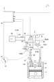
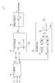
- FIG. 1 schematically shows an engine system equipped with a surge avoidance control device for an exhaust turbine turbocharger according to an embodiment of the present invention, wherein the VG turbocharger comprises a compressor bypass valve as an operating device.
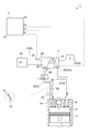
- FIG. 1 schematically shows an engine system provided with a surge avoidance control device for an exhaust turbine turbocharger according to an embodiment of the present invention, wherein the VG turbocharger comprises a waste gate valve as an operating device.
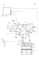
- FIG. 1 schematically shows an engine system provided with a surge avoidance control device for an exhaust turbine turbocharger according to an embodiment of the present invention, wherein a VG turbocharger also uses a variable nozzle mechanism (VG) as an operating device.
- VG variable nozzle mechanism
- FIG. 5 is a diagram illustrating a compressor map according to an embodiment of the present invention. It is a block diagram showing composition of a surge avoidance control device concerning one embodiment of the present invention. It is a block diagram explaining supercharging pressure control concerning one embodiment of the present invention. It is a flowchart which shows the supercharging pressure control method which concerns on one Embodiment of this invention.
- FIGS. 1 to 4 schematically show an engine system 1 provided with a surge avoidance control device 3 for an exhaust turbine turbocharger 2 according to an embodiment of the present invention.
- an engine system 1 includes an exhaust turbine turbocharger 2 and a surge avoidance control device 3.
- a gasoline engine engine system 1 is illustrated in FIGS. 1 to 4, the present invention is also applicable to a diesel engine.
- the engine system 1 is applicable to various fields, such as a car, a truck, a bus, a ship, and an industrial engine.
- each composition with which engine system 1 is provided is explained.
- the exhaust gas turbine supercharger 2 includes a turbine 2T rotated by exhaust gas from an engine 4 (engine body) and a compressor 2C rotationally driven by the turbine 2T, as shown in FIGS. More specifically, the compressor 2C installed in the intake passage 5 of the engine 4 and the turbine 2T installed in the exhaust passage 6 of the engine 4 are connected by the rotation shaft 2S. Then, when the exhaust gas discharged from the combustion chamber 41 of the engine 4 flows toward the outside through the exhaust passage 6, the compressor 2C coaxially coupled to the turbine 2T is rotated by rotating the turbine 2T, and the intake The intake air flowing through the passage 5 is compressed.
- the intake passage 5 communicates upstream with the intake duct (not shown), which is the intake of intake, and the inlet (intake inlet) of the compressor 2C.
- An intake passage 51 and a downstream side intake passage 52 communicating the outlet (intake and discharge port) of the compressor 2C with the intake port 43 of the engine 4 are formed. Then, air (intake air) taken in from the intake duct (not shown) flows through the intake passage 5 in the order of the upstream intake passage 51 and the downstream intake passage 52 toward the combustion chamber 41 of the engine 4.
- the intake air When flowing through the upstream side intake passage 51, the intake air passes through the air cleaner 54 provided in the upstream side intake passage 51 to remove foreign substances such as dust and dirt contained in the intake air, and then the compressor 2C is made into the inlet. Compressed as it passes from the to the outlet. Further, when the intake air compressed by the compressor 2C flows toward the combustion chamber 41 in the downstream side intake passage 52, the intercooler 55 for increasing the intake density by cooling provided in the downstream side intake passage 52, accelerator The throttle valve 56 for adjusting the flow rate of the intake air (intake air amount W) in accordance with the operation amount (accelerator opening Ac) of the pedal 13 sequentially passes through. Thereafter, the intake air is mixed with the fuel injected from the fuel injection nozzle 57 and enters the combustion chamber 41.
- the exhaust passage 6 communicates with the upstream exhaust passage 61 communicating the exhaust port 44 of the engine 4 with the inlet (exhaust inlet) of the turbine 2T, and the downstream communicating the outlet of the turbine 2T (exhaust outlet) with the outside.
- a side exhaust passage 62 is formed. Then, the exhaust gas (combustion gas) generated by the combustion in the combustion chamber 41 flows through the exhaust passage 6 in the order of the upstream exhaust passage 61 and the downstream exhaust passage 62 toward the outside.
- the exhaust gas having passed through the upstream exhaust passage 61 of the exhaust passage 6 rotates the turbine 2T when passing the turbine 2T from the inlet to the outlet. Thereafter, it flows outward through the downstream side exhaust passage 62.
- the intake passage 5 and the exhaust passage 6 are provided with various sensors used to detect the supercharging pressure of the turbocharger 2 during operation and the operating point of the compressor 2C, and the detection results by the various sensors Is used in surge avoidance control and boost pressure control by the surge avoidance control device 3 as described later.
- a boost pressure sensor 24 is provided in the downstream intake passage 52 to detect the supercharging pressure (outlet pressure Po) by the compressor 2C.
- an inlet pressure sensor 25 capable of detecting the pressure (inlet pressure Pi) at the inlet of the compressor 2C and an intake amount sensor 26 capable of detecting the intake amount W entering the compressor 2C are installed in the upstream side intake passage 51. .
- the operating point of the compressor 2C is obtained by the pressure ratio Pf (Po / Pi) of the outlet pressure Po to the inlet pressure Pi and the intake air amount W. It is sufficient that the operating point and the supercharging pressure of the compressor 2C can be obtained, and a sensor different from the above may be used, or another method may be adopted.
- the turbocharger 2 of the embodiment shown in FIGS. 1 to 4 will be respectively described.
- the turbocharger 2 of FIGS. 1 to 3 is a VG (Variable Geometry) turbocharger (variable) as illustrated.
- Capacitive turbocharger Capacitive turbocharger.
- the VG turbocharger has a variable nozzle mechanism 72 capable of adjusting the flow rate of the exhaust gas flowing into the turbine 2T (turbine blade). Then, the nozzle opening degree of the variable nozzle mechanism 72 is adjusted in accordance with the operating state of the engine 4 and the exhaust gas pressure toward the turbine moving blades is adjusted to control the supercharging pressure to the optimum condition.
- the nozzle opening degree is decreased at low rotation of the engine 4 to increase the exhaust gas pressure, and conversely, the nozzle opening degree is increased at high rotation of the engine 4.
- the supercharger 2 of FIG. 2 is also a waste gate valved turbocharger provided with a waste gate valve 73 as illustrated.
- the operating state of the engine 4 may be monitored, for example, by the number of revolutions N (rpm) of the engine 4 described later and the accelerator opening Ac (%).
- the supercharger 2 of FIG. 4 is a turbocharger with a wastegate valve (Wastegate Valve) together with the supercharger 2 of FIG. 2 as illustrated.
- the wastegate valve 73 is provided in a turbine bypass passage 63 communicating the downstream side and the upstream side of the turbine 2T in the exhaust passage 6 of the engine 4.
- the exhaust passage 6 includes the turbine bypass passage 63 communicating the upstream exhaust passage 61 and the downstream exhaust passage 62 so as to bypass the turbine 2T.
- the waste gate valve 73 is provided in the turbine bypass passage 63 so that the flow rate of the exhaust gas passing through the turbine bypass passage 63 can be controlled in accordance with the opening degree.
- the degree of opening of the waste gate valve 73 is between the fully open position and the fully closed position by operating the actuator 72a which is a mechanism for moving the valve according to the operation state of the engine 4 by the surge avoidance control device 3 described later. It is controlled. For example, in the fully closed position, the flow of exhaust gas passing through the turbine bypass passage 63 is completely shut off. In the fully open position, the turbine bypass passage 63 allows maximum exhaust gas flow. Further, at the intermediate opening between the fully closed position and the fully open position, the flow of exhaust gas according to the opening is allowed. For example, the exhaust gas pressure is increased by closing the opening of the waste gate valve 73 when the engine 4 is rotating at low speed, and conversely, the opening is opened when the engine 4 is rotating at high speed.
- the VG (variable nozzle mechanism 72) in FIGS. 1 to 3 and the waste gate valve 73 in FIG. 4 both control the rotational speed of the compressor 2C through control of the rotational speed of the turbine 2T. It is used for the supercharging pressure control for making the actual supercharging pressure (the outlet pressure Po) coincide with the target supercharging pressure Pt which is the target value of pressure. Thus, the fuel consumption of the engine 4 can be reduced.
- This supercharging pressure control is performed when the operating point of the compressor 2C is in a normal operating range Rn described later. The supercharging pressure control will be described later.
- the intake passage 5 is provided downstream and upstream of the compressor 2C, as shown in FIG. And a compressor bypass passage 53 that communicates with each other.
- the compressor bypass passage 53 establishes communication between the upstream intake passage 51 and the downstream intake passage 52 so as to bypass the compressor 2C.
- a compressor bypass valve 71 is provided in the compressor bypass passage 53 so that the flow rate of the intake air passing through the compressor bypass passage 53 can be controlled in accordance with the opening degree. More specifically, the degree of opening of the compressor bypass valve 71 is controlled between the fully open position and the fully closed position when the surge avoidance control device 3 described later operates the actuator 71 a.
- the flow of intake air passing through the compressor bypass passage 53 is completely shut off.
- the compressor bypass passage 53 allows maximum intake flow.
- the flow of intake air according to the opening is permitted.
- the surge avoidance control device 3 is a device for performing surging of the exhaust turbine supercharger 2 described above by controlling the opening degree of the operating device 7 capable of adjusting the operating point of the compressor 2C from full opening to full closing. (See FIGS. 1 to 4).
- the operating device 7 is a compressor bypass valve 71 provided in the compressor bypass passage 53.
- the pressure ratio Pf of the compressor 2C is reduced more directly than in the case where the variable nozzle mechanism 72 and the waste gate valve 73 are used as the operating device 7. Therefore, the responsiveness of control of the compressor operating point according to the surging avoidance operation can be enhanced.
- FIG. 1 the embodiment shown in FIG.
- the operating device 7 is a waste gate valve 73 provided in the turbine bypass passage 63.
- the operating device 7 is the variable nozzle mechanism 72 described above, and the variable nozzle mechanism 72 is also used in supercharging pressure control (described later).
- the surge avoidance control device 3 executes a surge avoidance control method of the exhaust gas turbine supercharger 2 described below.
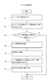
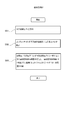
- FIG. 5 is a flow chart showing a surge avoidance control method of the exhaust gas turbine supercharger 2 according to one embodiment of the present invention.
- FIG. 6 is a diagram showing a compressor map Cm according to an embodiment of the present invention.
- the surge avoidance control method includes a surge detection step (S1 to S3), a surge avoidance opening calculation step (S4), a correction opening calculation step (S5), and an opening instruction value calculation. And step (S6).
- S1 to S3 the surge detection step
- S4 surge avoidance opening calculation step
- S5 correction opening calculation step
- S6 an opening instruction value calculation.
- a surge avoidance control method will be described along the flow of FIG.
- the surge avoidance control method of FIG. 5 will be described as being executed. Also, the operating point of the compressor 2C located in the surge operating range Rs described later is called a surge operating point (R1 and R2 in FIG. 6).
- a surge detection step is performed in steps S1 to S3 of FIG.
- the surge detection step (S1 to S3) is a step of determining whether or not the operating point of the compressor 2C is located in the surge operation range Rs, and as the flow of FIG. 5 is performed at predetermined timings, It is performed every predetermined timing.
- the above predetermined timing is a periodic timing.
- the present invention is not limited to this embodiment, and may be performed at a predetermined timing such as when the operating point of the compressor 2C changes in some other embodiments.
- the surge detection step also includes an operating point calculation step (S1) and a surge determination step (S2).
- an operating point calculating step of calculating an operating point of the compressor 2C is executed.
- the operating point of the compressor 2C is an index for detecting surging, and in the embodiment shown in FIGS. 1 to 4, the pressure ratio Pf (Po / Pi) of the outlet pressure Po to the inlet pressure Pi and the intake amount W become. ing.
- the information necessary to calculate the pressure ratio Pf and the intake amount W is acquired using, for example, the various sensors described above.
- a surge determination step is performed to determine whether the operating point of the compressor 2C calculated in step S1 is located in the surge operation range Rs. More specifically, by comparing the operating point of the compressor 2C with the compressor map Cm, it is determined in which region on the compressor map Cm the operating point of the compressor 2C is located.
- the compressor map Cm is a map in which the pressure ratio Pf is on the vertical axis and the intake air amount W is on the horizontal axis (see FIG. 6). Then, depending on where the operating point of the compressor 2C is located on the map, it is possible to determine the operating area and the efficiency of the turbocharger 2. A part of the compressor map Cm is shown in FIG.
- the surge operation area Rs is located on the left side and the normal operation area Rn is located on the right side with the surge line L as a boundary.
- the surge operation range Rs is a range in which surging may occur
- the normal operation range Rn is a range in which the supercharger 2 operates normally.
- step S3 When it is determined in the next step S3 that the operating point of the compressor 2C is located in the normal operation region Rn as a result of the determination in the surge determination step (S2), the flow of FIG. 5 is ended. Conversely, if it is determined that the operating point of the compressor 2C is located in the surge operating range Rs, the process proceeds to step S4 to execute the operation for avoiding surging.
- three operating points (R0, R1, R2) of the compressor 2C are shown as an example, and at a certain timing, the operating point R0 located in the normal operating area Rn on the compressor map Cm is At the next timing, a state is shown in which the vehicle moves to the operating point R1 located in the surge operating range Rs and is about to move to the next operating point R2.
- step S4 a surge avoidance opening degree calculation step of calculating the surge avoidance opening degree Ds is performed.
- the surge avoidance opening degree calculation step (S4) is an operation device necessary to move the operating point of the compressor 2C determined to be positioned in the surge operation range Rs in the surge detection step (S1 to S2) outside the surge operation range Rs.
- 7 is a step of calculating the surge avoidance opening degree Ds.
- the surge avoidance opening degree Ds is an opening degree calculated based on the surge operating point (R1 in FIG. 6). For example, by using the avoidance opening degree map Md showing the relationship between the pressure ratio Pf, the intake amount W, and the surge avoidance opening degree Ds, the surge avoidance opening is performed from the pressure ratio Pf and the intake amount W calculated in step S1.
- the degree Ds may be calculated.
- the avoidance opening map Md is prepared in advance through experiments and the like.
- step S5 a correction opening degree calculation step of calculating the correction opening degree Dc is executed.
- the correction opening Dc of the operating device 7 is determined based on the moving speed V of the operating point of the compressor 2C determined to be positioned in the surge operation region Rs in the surge detection step (S1 to S3).
- this correction opening degree Dc is calculated based on the moving speed V at the surge operating point (R1 in FIG. 6).
- the moving speed V can be calculated from the operating points of the two compressors 2C.
- the corrected opening degree Dc may be calculated from the moving speed V by using the corrected opening degree map Mc indicating the relationship between the moving speed V and the corrected opening degree Dc.
- the corrected opening degree Dc obtained by the corrected opening degree map Mc may be a value of the same dimension as the surge avoidance opening degree Ds, or may be a value indicating a correction coefficient for correcting the surge avoidance opening degree Ds.
- the corrected opening degree map Mc is prepared in advance through experiments and the like.
- step S6 an opening degree command value calculating step of calculating the opening degree command value D is executed.
- the opening degree command value calculating step (S6) is a step of calculating the opening degree command value D of the controller device 7 based on the surge avoidance opening degree Ds and the correction opening degree Dc.
- the opening degree command value D is calculated by calculating the surge avoidance opening degree Ds and the correction opening degree Dc. For example, if the surge avoidance opening Ds and the correction opening Dc have the same dimension, calculations such as addition and subtraction are performed, and if the correction opening Dc is the above-described correction coefficient, calculations such as multiplication and division are performed. May be done.
- the operation device control step is executed in step S7.
- the operation device control step (S7) is a step of outputting the calculated opening degree command value D to the operation device 7.
- a mechanism actuators 71a and 73b, variable nozzle mechanism 72 for moving the opening degree of the operating device 7 is controlled. Then, the flow of FIG. 5 ends after execution of step S7.
- the surge detection step calculates the moving speed V of the operating point of the compressor 2C calculated in step S1 in FIG. Based on the above, it may be executed by predicting whether the operating point of the compressor 2C located in the normal operating range Rn moves to the surge operating range Rs at the next timing. Specifically explaining with reference to FIG. 6, the moving speed V of the operating point R0 located in the normal operating region Rn is calculated based on the operating point R01 and the operating point R0 calculated before the operating point R0. Then, if the latest operating point R0 calculated in step S1 of FIG.
- step S2 of FIG. 5 is predicted to move to the operating point R1 at the next timing based on the calculated moving speed V, it moves to the surge operating area Rs. If it is predicted, it is determined in step S2 of FIG. 5 that the operating point of the compressor 2C is located in the surge operation region Rs, and steps S4 to S7 of FIG. 5 are executed.
- an operating point (R0 in FIG. 6) which is predicted to move to the surge operating area Rs at the next timing although it is located in the normal operating area Rn at this time is regarded as the surge operating point and the operating point
- the surge avoidance opening degree Ds may be calculated using the above-mentioned avoidance opening degree map Md or the like based on (R0 in FIG. 6).
- the predicted operating point which is the operating point of the compressor 2C predicted to be located in the surge operating range Rs, calculated based on the moving speed V of the operating point of the compressor 2C located in the normal operating range Rn (R1 in FIG. 6) ) Is temporarily replaced with the operating point (R0 in FIG. 6) from which the prediction is based, and is regarded as a surge operating point, and the surge avoidance opening Ds is calculated using the predicted operating point and the above-mentioned avoidance opening map Md etc. May be calculated. Further, the correction opening degree Dc is calculated based on the moving speed V calculated by R0 and R01 as described above. Thereby, the surge detection step can be performed in a feedforward manner. If it is determined that the operating point of the compressor 2C is located in the normal operating range Rn by the above method, the flow of FIG. 5 is ended.
- the degree of opening of the operating device 7 is controlled to an intermediate degree of opening rather than full opening as much as possible in order to suppress an excessive decrease in supercharging pressure due to execution of the surging avoidance operation (step S4 in FIG. 5) ⁇ S7).
- the problem is that reacceleration from this state is delayed when the supercharging pressure is reduced to the maximum.
- the operating point of the compressor 2C when the opening degree of the operating device 7 is controlled to the intermediate opening is more on the surge line L than when the opening degree of the operating device 7 is controlled fully open. It moves from the surge operation point to the normal operation region Rn in the vicinity.
- a predetermined position for example, operating point R 2, driving, etc.
- the surge operating point indicated by the operating point R1 is for all the sections ending at the above-mentioned predetermined position. It corresponds to the operating point at the time of transient transition.
- the surge operation point (R1) is moved to the normal operation region Rn in the vicinity of the surge line L based only on the information (coordinate point on the compressor map Cm) of the surge operation point (R1) at the time of transition.
- the opening degree command value D surge evasion opening degree Ds
- the compressor is finally There may occur a case where the operating point of 2C can not be moved to the normal operating range Rn.
- a larger value such that the surge operating point can be reliably moved to the normal operation area Rn from the moving speed V and the correction opening degree Dc can be obtained.
- the opening degree command value D can be adjusted according to the moving speed V, and the operating point of the compressor 2C is moved to the normal operating area Rn near the surge line L.
- steps S4 to S7 in FIG. 5 have been described as being performed based on the operating point of the compressor 2C (operating point R1 in FIG. 6) which is initially determined to be located in the surge operating range. It is not limited to Steps S4 to S7 in FIG. 5 may be performed based on a surge operating point at the time of transition when the operating point of the compressor 2C moves toward a predetermined position according to the change in the operating state of the engine 4. For example, in some other embodiments, this may be performed based on the operating point R2 of FIG. 6 or a transitional operating point after the operating point R2 in time.
- the surge avoidance opening degree Ds calculated based on the surge operating point at the transition time is By calculating the opening command value D in consideration of the corrected opening Dc, the surge in the normal operation region Rn is better than when the opening of the operating device 7 is fully opened or controlled to the opening side with a certain margin.
- the operating point of the compressor 2C can be controlled near the line L.
- the correction opening calculation step (S5 in FIG. 5) calculates the correction opening Dc so that the correction opening Dc becomes larger according to the magnitude of the movement velocity V, and the opening is
- the opening degree command value D of the controller device 7 may be calculated by adding the correction opening degree Dc to the surge avoidance opening degree Ds. This is because the pressure ratio Pf (Po / Pi) is expected to increase as the moving speed V of the operating point of the compressor 2C from the surge operating point increases, so the opening degree command value D is made larger to lower the pressure ratio Pf. Do. Conversely, the opening degree command value D is smaller as the moving speed V from the surge operating point is smaller.
- the operating point of the compressor 2C can be moved from the surge operating point to the vicinity of the limit of the surge line L by adjusting the opening degree command value D in accordance with the moving speed V of the operating point from the surge operating point. it can. As a result, it is possible to suppress an excessive decrease in boost pressure in surging avoidance control.
- FIG. 7 is a block diagram showing the configuration of the surge avoidance control device 3 according to an embodiment of the present invention.
- the surge avoidance control device 3 includes a surge detection unit 31, a surge avoidance opening degree calculation unit 32, a correction opening degree calculation unit 33, and an opening degree command value calculation unit 34.
- the surge avoidance control device 3 is configured by a computer such as an ECU (Electronic Control Device), and includes a CPU (processor) (not shown) and a memory (storage device) such as a ROM or a RAM.
- the CPU operates (for example, data operation) according to the instruction of the program loaded into the main storage device, thereby realizing each of the above-described functional units.
- the above-described compressor map Cm (FIG. 6), the avoidance opening map Md, and the correction opening map Mc are stored in the memory (not shown) of the surge avoidance control device 3, and each function unit is necessary. It is assumed that the map is configured to access and refer to a memory (not shown).
- Each of the above functional units of the surge avoidance control device 3 will be described below.
- the surge detection unit 31 determines whether or not the operating point of the compressor 2C is located in the surge operating range Rs at predetermined timings. That is, processing corresponding to the surge detection step (steps S1 to S3 in FIG. 5) of the above-described surge avoidance control method is executed. In the embodiment shown in FIG. 7, the surge detection unit 31 determines the outlet pressure Po (supercharging pressure) from the boost pressure sensor 24, the inlet pressure Pi from the inlet pressure sensor 25, and the intake amount from the intake amount sensor 26. W and each are input.
- Po supercharging pressure
- the surge detection unit 31 calculates the pressure ratio Pf (Po / Pi) of the outlet pressure Po to the inlet pressure Pi, and the operating point of the compressor 2C determined by the pressure ratio Pf and the intake amount W is located in the surge operation range Rs. Execute a surge judgment as to whether or not Further, the surge detection unit 31 is connected to the surge avoidance opening degree calculation unit 32 and the correction opening degree calculation unit 33, respectively, and information of the operating point of the compressor 2C determined as the surge operating point (pressure ratio Pf and intake The amount W) is output to the surge avoidance opening degree calculation unit 32 and the correction opening degree calculation unit 33, respectively.
- the predetermined timing is, for example, a periodic timing such as an operation cycle or a periodic interval determined based on the operation cycle.
- the surge avoidance opening degree calculation unit 32 is a surge avoidance opening degree of the operation device 7 necessary for moving the operating point of the compressor 2C determined to be located in the surge operation range Rs by the surge detection unit 31 out of the surge operation range Rs. Calculate Ds. That is, the process corresponding to the surge avoidance opening degree calculation step (step S4 of FIG. 5) of the above-described surge avoidance control method is executed.
- the surge avoidance opening degree calculation unit 32 refers to the avoidance opening degree map Md described above, and information on the surge operating point input from the surge detection unit 31 (pressure ratio Pf and intake amount) From W), the surge avoidance opening degree Ds is calculated.
- the surge avoidance opening degree calculation unit 32 is connected to the opening degree command value calculation unit 34, and is configured to output the calculated surge avoidance opening degree Ds to the opening degree command value calculation unit 34.
- the correction opening degree calculation unit 33 calculates the correction opening degree Dc of the controller device 7 based on the moving speed V of the operating point of the compressor 2C determined to be positioned in the surge operation region Rs by the surge detection unit 31. That is, processing corresponding to the correction opening calculation step (step S5 in FIG. 5) of the above-described surge avoidance control method is executed.
- the correction opening degree calculation unit 33 calculates the correction opening degree Dc when the information on the surge operating point (pressure ratio Pf and intake amount W) is input from the surge detection unit 31. Specifically, in the embodiment shown in FIG. 7, the pressure ratio Pf and the intake amount W are respectively differentiated and then squared.
- the moving velocity V is calculated from the value obtained by squaring the moving velocity V obtained by adding the square of the differential value of the pressure ratio Pf and the square of the differential value of the intake amount W.
- the correction opening degree calculation unit 33 calculates the correction opening degree Dc from the calculated movement speed V, using the correction opening degree map Mc indicating the relationship between the movement speed V and the correction opening degree Dc.
- the correction opening degree calculation unit 33 is connected to the opening degree command value calculation unit 34, and is configured to output the calculated correction opening degree Dc to the opening degree command value calculation unit 34.
- the opening degree command value calculation unit 34 calculates the opening degree command value D of the controller device 7 based on the surge avoidance opening degree Ds and the correction opening degree Dc. That is, the process corresponding to the opening degree command value calculating step (step S6 of FIG. 5) of the above-described surge avoidance control method is executed.
- the opening degree command value calculation unit 34 is connected to the surge avoidance opening degree calculation unit 32 and the correction opening degree calculation unit 33 respectively, and the surge avoidance opening degree calculation unit 32 eliminates the surge avoidance.
- the opening degree Ds is input, and the correction opening degree Dc is input from the correction opening degree calculating unit 33.
- the opening degree command value D is calculated by adding a calculation to the input surge avoidance opening degree Ds and the correction opening degree Dc. More specifically, the correction opening degree calculation unit 33 described above calculates the correction opening degree Dc such that the correction opening degree Dc becomes larger according to the size. Further, the opening degree command value calculation unit 34 calculates the opening degree command value D of the controller device 7 by adding the correction opening degree Dc to the surge avoidance opening degree Ds. Further, the opening degree command value calculation unit 34 is connected to the controller device 7 and is configured to output the opening degree command value D to the controller device 7. Thus, the controller device 7 is controlled to an opening degree corresponding to the opening degree command value D.
- the surge avoidance control device 3 that executes the surge avoidance control method of each of the above-described embodiments. As a result, it is possible to suppress an excessive decrease in boost pressure in surging avoidance control.
- FIG. 8 is a block diagram for explaining the supercharging pressure control according to the embodiment of the present invention.
- the supercharging pressure control is performed by the supercharging pressure control unit 8 realized as one functional unit of the surge avoidance control device 3.
- the present invention is not limited to this embodiment, and the supercharging pressure control may be performed by another ECU (electronic control unit) or a dedicated ECU.
- the surge detection unit 31, the surge avoidance opening degree calculation unit 32, the correction opening degree calculation unit 33, and the opening degree command value calculation unit 34 shown in FIG. 8 are the same as the contents described with reference to FIG. It is omitted because
- the supercharging pressure control unit 8 calculates a target supercharging pressure Pt on the downstream side of the compressor 2C based on the rotational speed N of the engine 4 and the accelerator opening Ac.
- the accelerator opening Ac (%) is a ratio of the operation amount of the accelerator pedal 13 to the maximum operation amount, and an accelerator opening sensor 14 capable of detecting the operation amount of the accelerator pedal 13.
- the accelerator opening Ac may be calculated in the front stage of the target boost pressure calculation unit 81, or the target boost pressure calculation unit 81 may use the accelerator based on the value detected by the accelerator opening sensor 14.
- the opening degree Ac may be calculated.
- the number of revolutions N (rpm) of the engine 4 is acquired using a sensor (not shown) capable of detecting the number of revolutions N of the engine 4.
- the target boost pressure calculation unit 81 is a target boost pressure map 86 showing the relationship between the rotation speed N (rpm) of the engine 4, the accelerator opening Ac (%), and the target boost pressure Pt (kPa). Is equipped.
- the target boost pressure calculation unit 81 refers to the above-mentioned target boost pressure map 86 on the memory (not shown) described above.
- the target boost pressure Pt is calculated.
- the boost pressure detection unit 82 is connected to the boost pressure sensor 24 described above, and detects the boost pressure (outlet pressure Po) when the actual boost pressure is input.
- the opening degree control unit 83 receives the calculation result from the comparison unit 84 that calculates the difference between the target boost pressure Pt and the boost pressure, and the comparison unit 84, and performs the above-described operation by feedback control such as PID.
- the feedback control unit 85 determines the nozzle opening degree of the variable nozzle mechanism 72 or the opening degree of the waste gate valve 73 (the opening degree I during supercharging pressure control) corresponding to the calculation result by the comparison unit 84.
- the opening degree I at the time of supercharging pressure control is output to the above-described supercharging pressure control device 9 so that the difference calculated at 84 becomes small, and feedback control is executed.
- the surge detection unit 31 mentioned above operates as the operating point of the compressor 2C.
- the process is configured to be executed when it is determined that the position is not located in the region Rs.
- the target boost pressure calculation unit 81 is connected to the surge detection unit 31 described above. Then, the surge detection unit 31 outputs signal information to the effect that the surge operating point has been determined to the target boost pressure calculation unit 81, and the target boost pressure calculation unit 81 receives the signal information input from the surge detection unit 31.
- the supercharging pressure control is stopped when the surging avoidance operation (steps S4 to S7 in FIG. 5) is performed.
- the supercharging pressure control is executed when the calculated operating point of the compressor 2C is located in the normal operating range Rn, and the surge avoidance control when the operating point of the compressor 2C is located in the surge operating range Rs. Switching is performed such that the surging avoidance operation in the method (FIG. 5) is performed.
- the operating point of the compressor 2C when the operating point of the compressor 2C is located in the normal operating range Rn, the actual supercharging pressure can be controlled to the target supercharging pressure Pt corresponding to the operating state of the engine 4.
- the surging avoidance operation can be performed without being affected by the case where the supercharging pressure control is continuously performed.
- the control since the variable nozzle mechanism 72 plays the role of both the operation device 7 and the supercharging pressure control device 9, the control is switched so that complex control is not performed. The intended control can be performed reliably.
- the control of the opening degree of the operating device 7 by the surging avoidance operation, and the supercharging pressure control device 9 by supercharging pressure control. The control of the degree of opening may be performed simultaneously.
- FIG. 9 is a flow chart showing a supercharging pressure control method according to an embodiment of the present invention.
- the supercharging pressure control method includes a target supercharging pressure calculation step (S91), a supercharging pressure detection step (S92), and an opening control step (S93). Each of these steps will be described along the flow of FIG. In the following, in the embodiment shown in FIGS. 1 to 4, it is assumed that the supercharging pressure control of FIG. 9 is executed by the surge avoidance control device 3 or the like having the above-described configuration.
- a target boost pressure calculation step of calculating target boost pressure Pt is executed.
- the target boost pressure calculation step (S91) is a step of calculating a target boost pressure Pt on the downstream side of the compressor 2C based on the rotation speed N of the engine 4 and the accelerator opening degree Ac.
- the accelerator opening degree Ac may be a ratio of the operation amount of the accelerator pedal 13 to the maximum operation amount.
- the target boost pressure map 86 showing the relationship between the rotation speed N (rpm) of the engine 4, the accelerator opening Ac (%), and the target boost pressure Pt (kPa)
- the target boost pressure Pt (kPa) may be calculated from the rotational speed N (rpm) and the accelerator opening Ac (%).
- step S92 a boost pressure detection step of detecting the boost pressure (outlet pressure Po) on the downstream side of the compressor 2C is performed.
- the boost pressure sensor 24 may be used to detect the boost pressure.
- step S93 an opening degree control step of controlling the opening degree of the boost pressure control device 9 is performed such that the boost pressure matches the target boost pressure Pt. That is, in the opening control step (S93), the nozzle opening of the variable nozzle mechanism 72 (the embodiment of FIGS. 1 to 3) or the waste gate valve so that the supercharging pressure matches the target supercharging pressure Pt. 73 (the embodiment of FIG. 4) are controlled.
- the compressor 2C is operated by the surge detection step (S1 to S3 in FIG. 5). It may be executed when it is determined that the point is not located in the surge operation range Rs.
- the actual supercharging pressure can be controlled to the target supercharging pressure Pt corresponding to the operating state of the engine 4.
- the surging avoidance operation can be performed without being affected by the case where the supercharging pressure control is continuously performed.
- variable nozzle mechanism 72 plays the role of both the control device 7 and the supercharging pressure control device 9, but in some other embodiments it is a turbocharger with a wastegate valve
- the compressor bypass valve 71 and the variable nozzle mechanism 72 are not provided, and the waste gate valve 73 plays the role of both the operation device 7 and the supercharging pressure control device 9 as in the embodiment shown in FIG. It may be configured as follows.
Abstract
エンジンからの排ガスによって回転するタービン及びタービンによって回転駆動するコンプレッサを有した排気タービン過給機のサージングを、コンプレッサの運転点を調整可能な操作機器の開度を全開から全閉の間で制御することにより行う排気タービン過給機のサージ回避制御方法において、コンプレッサの運転点がサージ運転領域に位置するか否かを所定のタイミング毎に判定するサージ検知ステップと、サージ検知ステップにおいてサージ運転領域に位置すると判定されたコンプレッサの運転点をサージ運転領域外に移動させるのに必要な操作機器のサージ回避開度を算出するサージ回避開度算出ステップと、サージ検知ステップにおいてサージ運転領域に位置すると判定されたコンプレッサの運転点の移動速度に基づいて、操作機器の補正開度を算出する補正開度算出ステップと、サージ回避開度と補正開度とに基づいて操作機器の開度指令値を算出する開度指令値算出ステップと、を備える。
Description
本開示は過給機の制御装置に関し、特に、過給機のサージングを回避する技術に関する。
自動車等に用いられるエンジンにおいては、エンジンの出力を向上させるために、エンジンの排気ガスのエネルギーでタービンを回転させ、タービンと同軸で連結されたコンプレッサで吸入空気(吸気)を圧縮してエンジンに供給する排気ターボチャージャが広く知られている。また、VG(Variable Geometry)ターボチャージャやWGバルブ(Wastegate)付きターボチャージャなどの可変機構を有するターボチャージャ(過給機)の採用が増えている。このような可変機構によって過給機の運転条件を制御することにより、エンジンの運転状態に適した圧力に過給圧を調整し、エンジンの燃費改善やドライバビリティの向上を実現している。その一方で、過給機は、運転条件によってはサージングと呼ばれる異常運転状態に陥ることがある。サージングはターボチャージャの破損につながることから、サージングを検知した場合にはその回避のための回避動作(回避制御)を一刻も早く行うことが重要である。
一般的には、サージングは、圧力や流量、温度等の変動により検知することが可能である。例えば、特許文献1~2では、コンプレッサの入口および出口における圧力の圧力比と、コンプレッサへの吸気の流入量(吸気量)とによって運転時のコンプレッサの運転点を検出している。そして、検出した運転点が、コンプレッサマップ上で定義されたサージングの発生の可能性があるサージ運転領域に位置するか否かを確認し、サージ運転領域に運転点が位置する場合にサージングの回避動作を実行している。また、サージングの回避動作の具体的な手法としては、特許文献1のように、コンプレッサバイパス弁の開度やVG(可変ノズル機構)のノズル開度、WGバルブの開度等の操作機器の開度を全開にすることが知られている。操作機器の開度を全開としない手法もあり、特許文献2では、コンプレッサバイパス弁を開く際には、サージ運転領域と正常運転領域の境界となるサージラインに対して、コンプレッサバイパス弁の応答性を加味したサージ防止ラインを設定し、サージ防止ラインを基準に運転点を制御することで、余裕をもってサージングの発生を防止することが開示されている。
しかしながら、上述した従来技術では下記に説明するような課題がある。例えば、VGターボチャージャでは可変ノズル機構のノズル開度を制御することにより、コンプレッサの過給圧は、エンジンの運転状態に基づいて決定される目標過給圧に制御される。そして、後述する図6に示すように、エンジンの運転状態の変化に応じた目標過給圧となるようにノズル開度が制御されるのに応じて、コンプレッサの運転点がコンプレッサマップ上における正常運転領域(Rn)からサージ運転領域(Rs)の所定の位置に移動する場合(R0→R2)を想定する。この場合において、例えば運転点の移動時間よりも十分に短い周期で運転点を監視する場合には、コンプレッサマップ上における正常運転領域に位置していた運転点(R0)が次の瞬間にはサージ運転領域に位置する(R1)ことが検知される。さらに、この検知後においても、サージングの回避動作が実行されない場合には、時間経過に伴って運転点がサージ運転領域を上記の所定の位置(R2)まで移動することになる。つまり、最初にサージ運転領域と判定された運転点を第1サージ運転点(R1)と呼ぶとすると、この第1サージ運転点(R1)は、サージ運転領域を運転点が上記所定の位置(R2)まで移動する全期間に対して中途となる(過渡時の)運転点に該当する。そして、例えば、上記の第1サージ運転点(R1)の情報(コンプレッサマップ上における座標点)のみで開度指令値を算出すると、過渡時の運転点(R1)で開度指令値を算出することになるため、そのサージ運転点(R1)以後の運転点の移動によっては、サージ運転領域外の正常運転領域に運転点を移動させることができない場合が生じ得る。
こうした状況においては、サージングを回避するために、コンプレッサの運転点がサージ運転領域に突入したことを検知した時点で操作機器の開度を全開することは有効であるが、同時に過給圧が大きく低下することになるため、この状態からの再加速が遅れるという課題がある。また、サージングに対してマージンを持って制御する手法では、特に、サージ運転領域と判定された運転点付近に運転点が留まるような場合には必要以上に操作機器の開度を大きくすることになり、サージラインの限界付近までコンプレッサを運転することができない。このため、必要以上に過給圧が低下すると共に、コンプレッサの性能を最大限に発揮することができない。
上述の事情に鑑みて、本発明の少なくとも一実施形態は、サージングの回避制御において過給圧の過度の低下を抑制可能な排気タービン過給機のサージ回避制御方法を提供することを目的とする。
(1)本発明の少なくとも一実施形態に係る排気タービン過給機のサージ回避制御方法は、
エンジンからの排ガスによって回転するタービン及び前記タービンによって回転駆動するコンプレッサを有した排気タービン過給機のサージングを、前記コンプレッサの運転点を調整可能な操作機器の開度を全開から全閉の間で制御することにより行う排気タービン過給機のサージ回避制御方法において、
前記コンプレッサの運転点がサージ運転領域に位置するか否かを所定のタイミング毎に判定するサージ検知ステップと、
前記サージ検知ステップにおいて前記サージ運転領域に位置すると判定された前記コンプレッサの運転点を前記サージ運転領域外に移動させるのに必要な前記操作機器のサージ回避開度を算出するサージ回避開度算出ステップと、
前記サージ検知ステップにおいて前記サージ運転領域に位置すると判定された前記コンプレッサの運転点の移動速度に基づいて、前記操作機器の補正開度を算出する補正開度算出ステップと、
前記サージ回避開度と前記補正開度とに基づいて前記操作機器の開度指令値を算出する開度指令値算出ステップと、を備えることを特徴とする。
上記(1)の構成によれば、コンプレッサの運転点を調整可能なコンプレッサバイパス弁、ウエストゲートバルブ弁、可変ノズル機構などとなる操作機器の開度指令値(開度)は、サージ回避開度と補正開度とに基づいて算出される。サージ回避開度は、エンジンの運転状態の変化に応じた目標過給圧に向けてコンプレッサの運転点が移動する際の過渡時の運転点(サージ運転点)から算出される開度である。また、補正開度は、サージ運転点からの運転点の移動速度に関する指標である。このように、エンジンの運転状態の変化に伴って移動するコンプレッサの運転点の過渡時において、その過渡時のサージ運転点に基づいて算出されるサージ回避開度に、上述した補正開度を加味して開度指令値を算出することで、操作機器の開度を全開にする場合や一定のマージンをもって開側に制御するよりも、サージ運転領域外(正常運転領域)におけるサージラインの近傍にコンプレッサの運転点を制御することができる。これによって、サージングの回避制御において過給圧の過度の低下を抑制することができ、コンプレッサの性能をより限界近くまで発揮することができると共に、サージングの回避のために操作機器の開度が変更された状態からの再加速を容易に行うことができる。また、コンプレッサの運転点の移動の過渡時において開度指令値を算出することで、サージングの回避動作を迅速に実行することができ、サージングの発生をより確実に回避することができる。
(2)幾つかの実施形態では、上記(1)の構成において、
前記補正開度算出ステップは、前記移動速度の大きさに応じて前記補正開度が大きくなるように前記補正開度を算出し、
前記開度指令値算出ステップは、前記サージ回避開度に前記補正開度を加算することで前記操作機器の開度指令値を算出する。
上記(2)の構成によれば、サージ運転点からの運転点の移動速度が大きいほど、コンプレッサの入口圧力に対する出口圧力の圧力比の増大が予想されるため、圧力比をより下げるために開度指令値を大きくする。逆に言えば、サージ運転点からの移動速度が小さいほど、開度指令値は小さい。このように、サージ運転点からの運転点の移動速度に応じて開度指令値を調整することで、コンプレッサの運転点をサージ運転点からサージラインの限界付近に移動することができる。これによって、サージングの回避制御において過給圧の過度の低下を抑制することができる。
(3)幾つかの実施形態では、上記(1)~(2)の構成において、
前記操作機器は、前記エンジンの吸気通路における前記コンプレッサの下流側と上流側とを連通するコンプレッサバイパス通路に設けられたコンプレッサバイパス弁である。
上記(3)の構成によれば、コンプレッサバイパス通路に設けられたコンプレッサバイパス弁の開度を制御することによりサージングを回避することができる。また、コンプレッサバイパス弁により、コンプレッサの入口圧力に対する出口圧力の圧力比を直接的に低減することができるため、サージングの回避動作に応じたコンプレッサの運転点の制御の応答性を高めることができる。
前記操作機器は、前記エンジンの吸気通路における前記コンプレッサの下流側と上流側とを連通するコンプレッサバイパス通路に設けられたコンプレッサバイパス弁である。
上記(3)の構成によれば、コンプレッサバイパス通路に設けられたコンプレッサバイパス弁の開度を制御することによりサージングを回避することができる。また、コンプレッサバイパス弁により、コンプレッサの入口圧力に対する出口圧力の圧力比を直接的に低減することができるため、サージングの回避動作に応じたコンプレッサの運転点の制御の応答性を高めることができる。
(4)幾つかの実施形態では、上記(1)~(2)の構成において、
前記操作機器は、前記タービンへ流入する排ガスの流速を調整可能な可変ノズル機構である。
上記(4)の構成によれば、可変ノズル機構のノズル開度を制御することによりサージングを回避することができる。また、VGターボチャージャが備える可変ノズル機構を操作機器とすることで、コストの増加を抑制することができる。
前記操作機器は、前記タービンへ流入する排ガスの流速を調整可能な可変ノズル機構である。
上記(4)の構成によれば、可変ノズル機構のノズル開度を制御することによりサージングを回避することができる。また、VGターボチャージャが備える可変ノズル機構を操作機器とすることで、コストの増加を抑制することができる。
(5)幾つかの実施形態では、上記(1)~(2)の構成において、
前記操作機器は、前記エンジンの排気通路における前記タービンの下流側と上流側とを連通するタービンバイパス通路に設けられたウエストゲート弁である。
上記(5)の構成によれば、タービンバイパス通路に設けられたウエストゲート弁の開度を制御することによりサージングを回避することができる。また、ウエストゲート弁付きターボチャージャが備えるウエストゲート弁を操作機器とすることで、コストの増加を抑制することができる。
前記操作機器は、前記エンジンの排気通路における前記タービンの下流側と上流側とを連通するタービンバイパス通路に設けられたウエストゲート弁である。
上記(5)の構成によれば、タービンバイパス通路に設けられたウエストゲート弁の開度を制御することによりサージングを回避することができる。また、ウエストゲート弁付きターボチャージャが備えるウエストゲート弁を操作機器とすることで、コストの増加を抑制することができる。
(6)幾つかの実施形態では、上記(3)~(5)の構成において、
前記エンジンの回転数とアクセル開度に基づいて、前記コンプレッサの下流側の目標過給圧を算出する目標過給圧算出ステップと、
前記コンプレッサの下流側の過給圧を検出する過給圧検出ステップと、
前記過給圧が前記目標過給圧に一致するように、前記タービンへ流入する排ガスの流速を調整可能な可変ノズル機構のノズル開度を制御する開度制御ステップと、をさらに備え、
前記目標過給圧算出ステップ、前記過給圧検出ステップ、および、前記開度制御ステップは、前記サージ検知ステップによって前記コンプレッサの運転点が前記サージ運転領域に位置しないと判定された場合に実行される。
上記(6)の構成によれば、コンプレッサの運転点が正常運転領域に位置する場合には可変ノズル機構によってエンジンの運転状態に応じた目標過給圧に実際の過給圧を制御することができる。また、コンプレッサの運転点がサージ運転領域に位置する場合には、操作機器(コンプレッサバイパス弁、可変ノズル機構、ウエストゲート弁)によって、サージングの回避を行うことができる。
(7)幾つかの実施形態では、上記(3)の構成において、
前記エンジンの回転数とアクセル開度に基づいて、前記コンプレッサの下流側の目標過給圧を算出する目標過給圧算出ステップと、
前記コンプレッサの下流側の過給圧を検出する過給圧検出ステップと、
前記過給圧が前記目標過給圧に一致するように、前記エンジンの排気通路における前記タービンの下流側と上流側とを連通するタービンバイパス通路に設けられたウエストゲート弁の開度を制御する開度制御ステップと、をさらに備え、
前記目標過給圧算出ステップ、前記過給圧検出ステップ、および、前記開度制御ステップは、前記サージ検知ステップによって前記コンプレッサの運転点が前記サージ運転領域に位置しないと判定された場合に実行される。
上記(7)の構成によれば、コンプレッサの運転点が正常運転領域に位置する場合にはウエストゲート弁によってエンジンの運転状態に応じた目標過給圧に実際の過給圧を制御することができる。また、コンプレッサの運転点がサージ運転領域に位置する場合には操作機器(コンプレッサバイパス弁)によってサージングの回避を行うことができる。
(8)本発明の少なくとも一実施形態に係る排気タービン過給機のサージ回避制御装置は、
エンジンからの排ガスによって回転するタービン及び前記タービンによって回転駆動するコンプレッサを有した排気タービン過給機のサージングを、前記コンプレッサの運転点を調整可能な操作機器の開度を全開から全閉の間で制御することにより行う排気タービン過給機のサージ回避制御装置において、
前記コンプレッサの運転点がサージ運転領域に位置するか否かを所定のタイミング毎に判定するサージ検知部と、
前記サージ検知部において前記サージ運転領域に位置すると判定された前記コンプレッサの運転点を前記サージ運転領域外に移動させるのに必要な前記操作機器のサージ回避開度を算出するサージ回避開度算出部と、
前記サージ検知部において前記サージ運転領域に位置すると判定された前記コンプレッサの運転点の移動速度に基づいて、前記操作機器の補正開度を算出する補正開度算出部と、
前記サージ回避開度と前記補正開度とに基づいて前記操作機器の開度指令値を算出する開度指令値算出部と、を備えることを特徴とする排気タービン過給機のサージ回避制御装置。
上記(8)の構成によれば、上記(1)のサージ回避制御方法を実行するサージ回避制御装置を提供することができる。これによって、サージングの回避制御において過給圧の過度の低下を抑制することができ、コンプレッサの性能をより限界近くまで発揮することができると共に、サージングの回避のために操作機器の開度が変更された状態からの再加速を容易に行うことができる。また、コンプレッサの運転点の移動の過渡時において開度指令値を算出することで、サージングの回避動作を迅速に実行することができ、サージングの発生をより確実に回避することができる。
(9)幾つかの実施形態では、上記(8)の構成において、
前記補正開度算出部は、前記移動速度の大きさに応じて前記補正開度が大きくなるように、前記補正開度を算出し、
前記開度指令値算出部は、前記サージ回避開度に前記補正開度を加算することで前記操作機器の開度指令値を算出する。
上記(9)の構成によれば、上記(2)のサージ回避制御方法を実行するサージ回避制御装置を提供することができる。これによって、サージングの回避制御において過給圧の過度の低下を抑制することができる。
前記補正開度算出部は、前記移動速度の大きさに応じて前記補正開度が大きくなるように、前記補正開度を算出し、
前記開度指令値算出部は、前記サージ回避開度に前記補正開度を加算することで前記操作機器の開度指令値を算出する。
上記(9)の構成によれば、上記(2)のサージ回避制御方法を実行するサージ回避制御装置を提供することができる。これによって、サージングの回避制御において過給圧の過度の低下を抑制することができる。
(10)幾つかの実施形態では、上記(8)~(9)の構成において、
前記操作機器は、前記エンジンの吸気通路における前記コンプレッサの下流側と上流側とを連通するコンプレッサバイパス通路に設けられたコンプレッサバイパス弁である。
上記(10)の構成によれば、上記(3)と同様に、サージングの回避動作に応じたコンプレッサの運転点の制御の応答性を高めつつ、サージングを回避することができる。
前記操作機器は、前記エンジンの吸気通路における前記コンプレッサの下流側と上流側とを連通するコンプレッサバイパス通路に設けられたコンプレッサバイパス弁である。
上記(10)の構成によれば、上記(3)と同様に、サージングの回避動作に応じたコンプレッサの運転点の制御の応答性を高めつつ、サージングを回避することができる。
(11)幾つかの実施形態では、上記(8)~(9)の構成において、
前記操作機器は、前記タービンへ流入する排ガスの流速を調整可能な可変ノズル機構である。
上記(11)の構成によれば、上記(4)と同様に、可変ノズル機構のノズル開度を制御することによりサージングを回避することができる。また、VGターボチャージャが備える可変ノズル機構を操作機器とすることで、コストの増加を抑制することができる。
前記操作機器は、前記タービンへ流入する排ガスの流速を調整可能な可変ノズル機構である。
上記(11)の構成によれば、上記(4)と同様に、可変ノズル機構のノズル開度を制御することによりサージングを回避することができる。また、VGターボチャージャが備える可変ノズル機構を操作機器とすることで、コストの増加を抑制することができる。
(12)幾つかの実施形態では、上記(8)~(9)の構成において、
前記操作機器は、前記エンジンの排気通路における前記タービンの下流側と上流側とを連通するタービンバイパス通路に設けられたウエストゲート弁である。また、ウエストゲート弁付きターボチャージャが備えるウエストゲート弁を操作機器とすることで、コストの増加を抑制することができる。
上記(12)の構成によれば、上記(5)と同様に、タービンバイパス通路に設けられたウエストゲート弁の開度を制御することによりサージングを回避することができる。
前記操作機器は、前記エンジンの排気通路における前記タービンの下流側と上流側とを連通するタービンバイパス通路に設けられたウエストゲート弁である。また、ウエストゲート弁付きターボチャージャが備えるウエストゲート弁を操作機器とすることで、コストの増加を抑制することができる。
上記(12)の構成によれば、上記(5)と同様に、タービンバイパス通路に設けられたウエストゲート弁の開度を制御することによりサージングを回避することができる。
(13)幾つかの実施形態では、上記(10)~(12)の構成において、
前記エンジンの回転数とアクセル開度に基づいて、前記コンプレッサの下流側の目標過給圧を算出する目標過給圧算出部と、
前記コンプレッサの下流側の過給圧を検出する過給圧検出部と、
前記過給圧が前記目標過給圧に一致するように、前記タービンへ流入する排ガスの流速を調整可能な可変ノズル機構のノズル開度を制御する開度制御部と、をさらに備え、
前記目標過給圧算出部、前記過給圧検出部、および、前記開度制御部は、前記サージ検知部によって前記コンプレッサの運転点が前記サージ運転領域に位置しないと判定された場合に実行される。
上記(13)の構成によれば、上記(6)と同様に、コンプレッサの運転点が正常運転領域に位置する場合には可変ノズル機構によってエンジンの運転状態に応じた目標過給圧に実際の過給圧を制御することができる。また、コンプレッサの運転点がサージ運転領域に位置する場合には、操作機器(コンプレッサバイパス弁、可変ノズル機構、ウエストゲート弁)によって、サージングの回避を行うことができる。
(14)幾つかの実施形態では、上記(10)の構成において、
前記エンジンの回転数とアクセル開度に基づいて、前記コンプレッサの下流側の目標過給圧を算出する目標過給圧算出部と、
前記コンプレッサの下流側の過給圧を検出する過給圧検出部と、
前記過給圧が前記目標過給圧に一致するように、前記エンジンの排気通路における前記タービンの下流側と上流側とを連通するタービンバイパス通路に設けられたウエストゲート弁の開度を制御する開度制御部と、をさらに備え、
前記目標過給圧算出部、前記過給圧検出部、および、前記開度制御部は、前記サージ検知部によって前記コンプレッサの運転点が前記サージ運転領域に位置しないと判定された場合に実行される。
上記(14)の構成によれば、上記(7)と同様に、コンプレッサの運転点が正常運転領域に位置する場合にはウエストゲート弁によってエンジンの運転状態に応じた目標過給圧に実際の過給圧を制御することができる。また、コンプレッサの運転点がサージ運転領域に位置する場合には操作機器(コンプレッサバイパス弁)によってサージングの回避を行うことができる。
本発明の少なくとも一実施形態によれば、サージングの回避制御において過給圧の過度の低下を抑制可能な排気タービン過給機のサージ回避制御方法が提供される。
以下、添付図面を参照して本発明の幾つかの実施形態について説明する。ただし、実施形態として記載されている又は図面に示されている構成部品の寸法、材質、形状、その相対的配置等は、本発明の範囲をこれに限定する趣旨ではなく、単なる説明例にすぎない。
一方、一の構成要素を「備える」、「具える」、「具備する」、「含む」、又は、「有する」という表現は、他の構成要素の存在を除外する排他的な表現ではない。
一方、一の構成要素を「備える」、「具える」、「具備する」、「含む」、又は、「有する」という表現は、他の構成要素の存在を除外する排他的な表現ではない。
図1~図4は、本発明の一実施形態に係る排気タービン過給機2のサージ回避制御装置3を備えるエンジンシステム1を概略的に示す図である。図1~図4に示されるように、エンジンシステム1は、排気タービン過給機2と、サージ回避制御装置3とを備える。図1~図4にはガソリンエンジンのエンジンシステム1が例示されているが、本発明はディーゼエンジンに適用もできる。また、エンジンシステム1は、自動車、トラック、バス、船舶、産業用エンジン等の様々な分野に適用可能である。
以下、エンジンシステム1が備える各々の構成について説明する。
以下、エンジンシステム1が備える各々の構成について説明する。
排気タービン過給機2は、図1~図4に示されるように、エンジン4(エンジン本体)からの排ガスによって回転するタービン2T及びタービン2Tによって回転駆動するコンプレッサ2Cを有する。より詳細には、エンジン4の吸気通路5に設置されたコンプレッサ2Cと、エンジン4の排気通路6に設置されたタービン2Tとが回転軸2Sで連結されている。そして、エンジン4の燃焼室41から排出される排ガスが排気通路6を通って外部に向けて流れる際にタービン2Tを回転させることにより、タービン2Tと同軸で結合されたコンプレッサ2Cが回転し、吸気通路5を流れる吸気を圧縮する。
図1~図4に示される実施形態では、図示されるように、吸気通路5は、吸気の取り入れ口である不図示の吸気ダクトとコンプレッサ2Cの入口(吸気流入口)とを連通する上流側吸気通路51、および、コンプレッサ2Cの出口(吸気排出口)とエンジン4の吸気ポート43とを連通する下流側吸気通路52から形成されている。そして、吸気ダクト(不図示)から吸入された空気(吸気)はエンジン4の燃焼室41に向けて上流側吸気通路51、下流側吸気通路52の順に吸気通路5を流れる。上流側吸気通路51を流れる際には、吸気は、上流側吸気通路51に設けられたエアクリーナ54を通過することよって吸気に含まれる塵や埃などの異物が除去された後、コンプレッサ2Cを入口から出口へと通過する際に圧縮される。また、コンプレッサ2Cにより圧縮された吸気は、下流側吸気通路52を燃焼室41に向けて流れる際に、下流側吸気通路52に設けられた、冷却により吸気密度を高めるためのインタークーラ55、アクセルペダル13の操作量(アクセル開度Ac)に応じて吸気の流量(吸気量W)を調整するためのスロットルバルブ56を順に通過する。その後、吸気は、燃料噴射ノズル57から噴射される燃料と混合されて燃焼室41に入る。
他方、排気通路6は、エンジン4の排気ポート44とタービン2Tの入口(排気流入口)とを連通する上流側排気通路61と、タービン2Tの出口(排気排出口)と外部とを連通する下流側排気通路62とから形成されている。そして、燃焼室41での燃焼により生じた排ガス(燃焼ガス)は、外部に向けて上流側排気通路61、下流側排気通路62の順に排気通路6を流れる。排気通路6の上流側排気通路61を通過した排ガスは、タービン2Tを入口から出口へと通過する際にタービン2Tを回転させる。その後、下流側排気通路62を通って外部に向けて流れていく。
また、吸気通路5や排気通路6には、運転中の過給機2の過給圧やコンプレッサ2Cの運転点を検出するのに使用される各種センサが設けられており、各種センサによる検出結果は、後述するようなサージ回避制御装置3によるサージ回避制御や過給圧制御で使用される。図1~図4に示される実施形態では、図示されるように、コンプレッサ2Cによる過給圧(出口圧力Po)を検出するために、ブースト圧センサ24が下流側吸気通路52に設置されている。また、コンプレッサ2Cの入口の圧力(入口圧力Pi)を検出可能な入口圧力センサ25と、コンプレッサ2Cへ入る吸気量Wを検出可能な吸気量センサ26とが上流側吸気通路51に設置されている。また、コンプレッサ2Cの運転点を、入口圧力Piに対する出口圧力Poの圧力比Pf(Po/Pi)および吸気量Wにより得るようになっている。なお、コンプレッサ2Cの運転点や過給圧を取得できれば良いのであり、上記とは異なるセンサを用いても良いし、他の手法を採用しても良い。
ここで、図1~図4に示される実施形態の過給機2についてそれぞれ説明すると、図1~図3の過給機2は、図示されるように、VG(Variable Geometry)ターボチャージャ(可変容量型ターボチャージャ)である。VGターボチャージャは、タービン2T(タービン動翼)へ流入する排ガスの流速を調整可能な可変ノズル機構72を有している。そして、エンジン4の運転状態に合わせて可変ノズル機構72のノズル開度を調整し、タービン動翼へ向かう排ガス圧力を調整することにより、過給圧を最適条件にコントロールする。例えば、周知なように、エンジン4の低回転時にはノズル開度を小さくして排ガス圧力を高め、逆に、エンジン4の高回転時にはノズル開度を大きくする。なお、図2の過給機2は、図示されるように、ウエストゲート弁73(Wastegate Valve)を備えるウエストゲート弁付きターボチャージャでもある。なお、エンジン4の運転状態は、例えば、後述するエンジン4の回転数N(rpm)、アクセル開度Ac(%)で監視されても良い。
他方、図4の過給機2は、図示されるように、図2の過給機2と共に、ウエストゲート弁(Wastegate Valve)付きターボチャージャである。ウエストゲート弁73は、エンジン4の排気通路6におけるタービン2Tの下流側と上流側とを連通するタービンバイパス通路63に設けられている。換言すれば、排気通路6は、タービン2Tをバイパスするようにして、上流側排気通路61と下流側排気通路62とを連通するタービンバイパス通路63を備えている。そして、このウエストゲート弁73は、タービンバイパス通路63に設けられることで、タービンバイパス通路63を通過する排ガスの排ガスの流量をその開度に応じて制御することが可能に構成されている。このウエストゲート弁73の開度は、後述するサージ回避制御装置3が、エンジン4の運転状態に合わせて、バルブを動かす機構であるアクチュエータ72aを操作することで全開位置から全閉位置の間で制御される。例えば、全閉位置では、タービンバイパス通路63を通過する排ガスの流れは完全に遮断される。全開位置では、タービンバイパス通路63には最大限の排ガスの流れが許容される。また、全閉位置と全開位置との間の中間開度では、開度に応じた排ガスの流れが許容される。例えば、エンジン4の低回転時にはウエストゲート弁73の開度を閉側にすることで排ガス圧力を高め、逆に、エンジン4の高回転時には開度を開側にする。
そして、図1~図3のVG(可変ノズル機構72)および図4のウエストゲート弁73は、いずれもタービン2Tの回転数の制御を通して、コンプレッサ2Cの回転数を制御するものであり、過給圧の目標値となる目標過給圧Ptに実際の過給圧(出口圧力Po)を一致させるための過給圧制御に利用される。これによって、エンジン4の燃費低減が図られる。この過給圧制御は、コンプレッサ2Cの運転点が後述する正常運転領域Rnにある場合に行われる。なお、過給圧制御については後述する。
また、図1、図4に示される実施形態では、図2~図3に示される実施形態にはない構成として、図示されるように、吸気通路5は、コンプレッサ2Cの下流側と上流側とを連通するコンプレッサバイパス通路53を備えている。換言すれば、コンプレッサバイパス通路53は、コンプレッサ2Cをバイパスするようにして上流側吸気通路51と下流側吸気通路52とを連通する。そして、このコンプレッサバイパス通路53にはコンプレッサバイパス弁71が設けられており、コンプレッサバイパス通路53を通過する吸気の流量をその開度に応じて制御することが可能に構成されている。より詳細には、コンプレッサバイパス弁71の開度は、後述するサージ回避制御装置3がアクチュエータ71aを操作することで全開位置から全閉位置の間で制御される。例えば、全閉位置では、コンプレッサバイパス通路53を通過する吸気の流れは完全に遮断される。全開位置では、コンプレッサバイパス通路53には最大限の吸気の流れが許容される。また、全閉位置と全開位置との間の中間開度では、開度に応じた吸気の流れが許容される。
サージ回避制御装置3は、上述した排気タービン過給機2のサージングを、コンプレッサ2Cの運転点を調整可能な操作機器7の開度を全開から全閉の間で制御することにより行うための装置である(図1~図4参照)。図1、図4に示される実施形態では、操作機器7は、コンプレッサバイパス通路53に設けられたコンプレッサバイパス弁71である。この場合には、コンプレッサバイパス弁71を操作機器7とすることにより、可変ノズル機構72やウエストゲート弁73を操作機器7とする場合よりも、より直接的にコンプレッサ2Cの圧力比Pfを低減することができるため、サージングの回避動作に応じたコンプレッサの運転点の制御の応答性を高めることができる。一方、図2に示される実施形態では、操作機器7は、タービンバイパス通路63に設けられたウエストゲート弁73である。図3に示される実施形態では、操作機器7は上記の可変ノズル機構72であり、また、可変ノズル機構72では過給圧制御(後述)においても用いられる。これらの場合には、可変ノズル機構72やウエストゲート弁73付きの過給機2では、コンプレッサバイパス弁71を新たに設ける必要はなく、コストの増加を抑制することができる。
そして、サージ回避制御装置3は、下記に説明する排気タービン過給機2のサージ回避制御方法を実行する。
そして、サージ回避制御装置3は、下記に説明する排気タービン過給機2のサージ回避制御方法を実行する。
以下、排気タービン過給機2のサージ回避制御方法(以下、適宜、サージ回避制御方法という)を、図5~図6を用いて説明する。図5は、本発明の一実施形態に係る排気タービン過給機2のサージ回避制御方法を示すフロー図である。また、図6は、本発明の一実施形態に係るコンプレッサマップCmを示す図である。図5に示されるように、サージ回避制御方法は、サージ検知ステップ(S1~S3)と、サージ回避開度算出ステップ(S4)と、補正開度算出ステップ(S5)と、開度指令値算出ステップ(S6)と、を備える。
以下、図5のフローに沿ってサージ回避制御方法を説明する。なお、以下では、図1~図4に示される実施形態において、図5のサージ回避制御方法が実行されるものとして説明する。また、後述するサージ運転領域Rsに位置するコンプレッサ2Cの運転点をサージ運転点と呼ぶ(図6のR1やR2)。
以下、図5のフローに沿ってサージ回避制御方法を説明する。なお、以下では、図1~図4に示される実施形態において、図5のサージ回避制御方法が実行されるものとして説明する。また、後述するサージ運転領域Rsに位置するコンプレッサ2Cの運転点をサージ運転点と呼ぶ(図6のR1やR2)。
図5のステップS1~S3においてサージ検知ステップが実行される。サージ検知ステップ(S1~S3)は、コンプレッサ2Cの運転点がサージ運転領域Rsに位置するか否かを判定するステップであり、図5のフローが所定のタイミング毎に行われるのに伴って、所定のタイミング毎に行われる。図5に示される実施形態では、上記の所定のタイミングは周期的なタイミングとなっている。ただし、本発明はこの実施形態に限定されず、他の幾つかの実施形態では、コンプレッサ2Cの運転点が変わる時などの所定のタイミングで実行されても良い。また、このサージ検知ステップは、運転点算出ステップ(S1)と、サージ判定ステップ(S2)を含んでいる。
具体的には、図5のステップS1において、コンプレッサ2Cの運転点を算出する運転点算出ステップが実行される。コンプレッサ2Cの運転点はサージングを検知するための指標であり、図1~図4に示される実施形態では、入口圧力Piに対する出口圧力Poの圧力比Pf(Po/Pi)および吸気量Wとなっている。この圧力比Pfおよび吸気量Wを算出するのに必要な情報は、例えば上述した各種センサを用いて取得される。
また、ステップS2において、ステップS1で算出されたコンプレッサ2Cの運転点がサージ運転領域Rsに位置するか否かを判定するサージ判定ステップが実行される。より詳細には、コンプレッサ2Cの運転点とコンプレッサマップCmとを比較することにより、コンプレッサ2Cの運転点がコンプレッサマップCm上のどの領域に位置するかを判定する。一般的に、コンプレッサマップCmは、縦軸に圧力比Pf、横軸に吸気量Wとしたマップである(図6参照)。そして、コンプレッサ2Cの運転点がマップ上のどこに位置するかによって、過給機2の作動領域や効率が判断可能となっている。図6にはコンプレッサマップCmの一部が示されており、図示されるように、サージラインLを境に、サージ運転領域Rsは左側に位置し、正常運転領域Rnは右側に位置する。サージ運転領域Rsはサージングが発生する恐れがある領域であり、正常運転領域Rnは過給機2が正常に作動する領域である。
次のステップS3において、サージ判定ステップ(S2)による判定の結果、コンプレッサ2Cの運転点が正常運転領域Rnに位置すると判定された場合には、図5のフローを終了する。逆に、コンプレッサ2Cの運転点がサージ運転領域Rsに位置すると判定された場合には、サージング回避のための動作を実行するためにステップS4に進む。図6には、例としてコンプレッサ2Cの運転点(R0、R1、R2)が3つ示されており、あるタイミングにおいて、コンプレッサマップCm上における正常運転領域Rnに位置していた運転点R0が、次のタイミングにおいて、サージ運転領域Rsに位置する運転点R1に移動し、さらに次の運転点R2に移動しようとしている状態が示されている。この例示の場合には、サージ検知ステップ(S1~S3)において検知された運転点がR0であった時にはそのままフローを終了する。逆に、運転点がR1やR2であった時には次のステップS4以降のサージングの回避のための動作(サージングの回避動作)に進むことになる。
ステップS4において、サージ回避開度Dsを算出するサージ回避開度算出ステップが実行される。サージ回避開度算出ステップ(S4)は、サージ検知ステップ(S1~S2)においてサージ運転領域Rsに位置すると判定されたコンプレッサ2Cの運転点をサージ運転領域Rs外に移動させるのに必要な操作機器7のサージ回避開度Dsを算出するステップである。このサージ回避開度Dsは、サージ運転点(図6ではR1)に基づいて算出される開度である。例えば、上記の圧力比Pf、吸気量W、およびサージ回避開度Dsとの関係を示す回避開度マップMdを用いることで、ステップS1で算出された圧力比Pfおよび吸気量Wからサージ回避開度Dsを算出しても良い。回避開度マップMdは、実験等を通して予め用意される。
ステップS5において、補正開度Dcを算出する補正開度算出ステップが実行される。補正開度算出ステップ(S5)は、サージ検知ステップ(S1~S3)においてサージ運転領域Rsに位置すると判定されたコンプレッサ2Cの運転点の移動速度Vに基づいて、操作機器7の補正開度Dcを算出するステップである。図6に示される実施形態では、この補正開度Dcは、サージ運転点(図6ではR1)における移動速度Vに基づいて算出される。この移動速度Vは、2つのコンプレッサ2Cの運転点から算出することが可能である。具体的には、運転点R0から運転点R1に運転点が移動する際の時間と、コンプレッサマップCm上おける運転点R0と運転点R1の距離から算出することができ、最も早く検出されたサージ運転点に基づいて算出するため、移動速度Vの迅速な算出が可能となる。あるいは、運転点R2など、運転点R1からさらに進んだコンプレッサ2Cの運転点を用いても良く、運転点R1から運転点R2に運転点が移動する際の時間と、コンプレッサマップCm上おける運転点R1から運転点R2の距離から算出することもできる。そして、移動速度Vと補正開度Dcとの関係を示す補正開度マップMcを用いることで、移動速度Vから補正開度Dcを算出しても良い。この補正開度マップMcにより得られる補正開度Dcは、サージ回避開度Dsと同じ次元の値でも良いし、サージ回避開度Dsを補正するための補正係数を示す値であっても良い。補正開度マップMcは、実験等を通して予め用意される。
ステップS6において、開度指令値Dを算出する開度指令値算出ステップが実行される。開度指令値算出ステップ(S6)は、サージ回避開度Dsと補正開度Dcとに基づいて操作機器7の開度指令値Dを算出するステップである。具体的には、サージ回避開度Dsと補正開度Dcとを演算することにより開度指令値Dを算出する。例えば、サージ回避開度Dsと補正開度Dcとが同じ次元を有する場合には加算、減算等の演算が行われ、補正開度Dcが上述の補正係数であれば、乗算、除算などの演算が行われても良い。
また、図5に示される実施形態では、ステップS7において操作機器制御ステップが実行される。操作機器制御ステップ(S7)は、算出された開度指令値Dを操作機器7に出力するステップである。この開度指令値Dに応じて、操作機器7の開度を動かす機構(アクチュエータ71a、73b、可変ノズル機構72)が制御される。そして、ステップS7の実行後に図5のフローは終了する。
ただし、本発明は上述した実施形態に限定されない。例えば、他の幾つかの実施形態では、サージ検知ステップ(図5のS1~S3)は、図5のステップS1で算出されたコンプレッサ2Cの運転点の移動速度Vを算出し、この移動速度Vに基づいて、正常運転領域Rnに位置しているコンプレッサ2Cの運転点が次のタイミングにおいてサージ運転領域Rsに移動するか否かを予測することにより実行されても良い。図6を用いて具体的に説明すると、正常運転領域Rnに位置する運転点R0の移動速度Vを、運転点R0の前に算出された運転点R01および運転点R0に基づいて算出する。そして、図5のステップS1で算出された最新の運転点R0が、算出された移動速度Vに基づいて、次のタイミングでは運転点R1に移動すると予測されるなど、サージ運転領域Rsに移動すると予測される場合には、図5のステップS2においてコンプレッサ2Cの運転点がサージ運転領域Rsに位置すると判定し、図5のステップS4~ステップS7を実行する。例えば、このような現時点では正常運転領域Rnに位置するものの、次のタイミングにおいてサージ運転領域Rsに移動すると予測される運転点(図6ではR0)を、サージ運転点とみなして、その運転点(図6ではR0)に基づいて上記の回避開度マップMdを用いるなどして、サージ回避開度Dsを算出しても良い。あるいは、正常運転領域Rnに位置するコンプレッサ2Cの運転点の移動速度Vに基づいて算出された、サージ運転領域Rsに位置すると予測されるコンプレッサ2Cの運転点である予測運転点(図6ではR1)を、予測の元になる運転点(図6ではR0)に一時的に置き換えると共にサージ運転点とみなして、その予測運転点と上記の回避開度マップMdなどを用いてサージ回避開度Dsを算出しても良い。また、補正開度Dcは、上述のようにR0およびR01で算出される上記の移動速度Vに基づいて算出される。これによって、サージ検知ステップをフィードフォワード的に実行することができる。なお、上記の方法により、コンプレッサ2Cの運転点が正常運転領域Rnに位置すると判定された場合には、図5のフローを終了することになる。
ここで、上述したように、操作機器7の開度指令値Dを、サージ回避開度Dsおよび補正開度Dcに基づいて算出する理由を説明する。本発明では、サージングの回避動作の実行による過給圧の過度の低下を抑制するために、操作機器7の開度を可能な限り、全開ではなく中間開度に制御する(図5のステップS4~S7)。例えば、操作機器7の開度を全開にするとサージングの回避は可能であるものの、過給圧が最大限低下することにより、この状態からの再加速が遅れるといった課題が生じるためである。そして、コンプレッサマップCm上において、操作機器7の開度を中間開度に制御した場合のコンプレッサ2Cの運転点は、操作機器7の開度を全開に制御した場合よりも、よりサージラインLの近傍における正常運転領域Rnにサージ運転点から移動することになる。
例えば、図6に示されるように、エンジン4の運転状態の変化などに伴って、コンプレッサマップCm上において、エンジン4の運転状態の変化に応じた所定の位置(例えば、運転点R2や、運転点R2以降の運転点)に向けてコンプレッサ2Cの運転点が移動する場合、上述したように、運転点R1で示されるサージ運転点は、上記の所定の位置を終点とする全区間に対して中途となる過渡時の運転点に該当する。そして、この過渡時のサージ運転点(R1)の情報(コンプレッサマップCm上における座標点)のみに基づいて、サージラインLの近傍における正常運転領域Rnにサージ運転点(R1)が移動するように操作機器7の開度を決定した場合には(つまり、開度指令値D=サージ回避開度Ds)、そのサージ運転点(R1)以後の運転点の移動によっては、最終的には、コンプレッサ2Cの運転点を正常運転領域Rnに移動させることができない場合が生じ得る。このような状況を回避しようとする場合には、例えば移動速度Vと補正開度Dcとから、サージ運転点を正常運転領域Rnに確実に移動させることが可能となるような、より大きな値を有するサージ回避開度Dsが求められるように回避開度マップMdを作成するなど、必要以上に大きな開度となるようにマージンを持ってサージ回避開度Dsを算出する方法が考えられる。ところが、この方法では、そのマージンの分だけ必要以上に大きい過給圧の低下を許容することになってしまう。そこで、本発明では、コンプレッサ2Cの運転点がサージ運転領域Rsに位置することが検出されると、上述したようにサージ回避開度Dsのみならず、補正開度Dcを用いて開度指令値Dを算出することで、移動速度Vに応じた開度指令値Dの調整を可能とし、サージラインLの近傍の正常運転領域Rnにコンプレッサ2Cの運転点を移動させている。
なお、上記では、図5のステップS4~S7は、サージ運転領域に位置すると最初に判定されたコンプレッサ2Cの運転点(図6の運転点R1)に基づいて行われるものとして説明したが、これには限定されない。図5のステップS4~S7は、エンジン4の運転状態の変化に応じた所定の位置に向けてコンプレッサ2Cの運転点が移動する際の過渡時のサージ運転点に基づいて実行されれば良い。例えば、他の幾つかの実施形態では、図6の運転点R2や、時間的に運転点R2以降の過渡時の運転点に基づいて実行されても良い。
上記の構成によれば、エンジン4の運転状態の変化に伴って移動するコンプレッサ2Cの運転点の過渡時において、その過渡時のサージ運転点に基づいて算出されるサージ回避開度Dsに、上述した補正開度Dcを加味して開度指令値Dを算出することで、操作機器7の開度を全開にする場合や一定のマージンをもって開側に制御するよりも、正常運転領域RnにおけるサージラインLの近傍にコンプレッサ2Cの運転点を制御することがでる。これによって、サージングの回避制御において過給圧の過度の低下を抑制することができ、コンプレッサ2Cの性能をより限界近くまで発揮することができると共に、サージングの回避のために操作機器7の開度が変更された状態からの再加速を容易に行うことができる。また、コンプレッサ2Cの運転点の移動の過渡時において開度指令値Dを算出することで、サージングの回避動作を迅速に実行することができ、サージングの発生をより確実に回避することができる。
また、幾つかの実施形態では、補正開度算出ステップ(図5のS5)は、移動速度Vの大きさに応じて補正開度Dcが大きくなるように補正開度Dcを算出し、開度指令値算出ステップ(図5のS6)は、サージ回避開度Dsに補正開度Dcを加算することで操作機器7の開度指令値Dを算出しても良い。これは、サージ運転点からのコンプレッサ2Cの運転点の移動速度Vが大きいほど圧力比Pf(Po/Pi)の増大が予想されため、圧力比Pfをより下げるために開度指令値Dを大きくする。逆に言えば、サージ運転点からの移動速度Vが小さいほど、開度指令値Dは小さい。このように、サージ運転点からの運転点の移動速度Vに応じて開度指令値Dを調整することで、コンプレッサ2Cの運転点をサージ運転点からサージラインLの限界付近に移動することができる。これによって、サージングの回避制御において過給圧の過度の低下を抑制することができる。
次に、上述したサージ回避制御方法(図5)を実行するサージ回避制御装置3の具体的な構成について、図7を用いて説明する。図7は、本発明の一実施形態に係るサージ回避制御装置3の構成を示すブロック図である。図7に示されるように、サージ回避制御装置3は、サージ検知部31と、サージ回避開度算出部32と、補正開度算出部33と、開度指令値算出部34と、を備える。このサージ回避制御装置3は、ECU(電子制御装置)などのコンピュータで構成されており、図示しないCPU(プロセッサ)や、ROMやRAMといったメモリ(記憶装置)を備えている。そして、主記憶装置にロードされたプログラムの命令に従ってCPUが動作(データの演算など)することで、上記の各機能部を実現する。なお、サージ回避制御装置3のメモリ(不図示)には、上述したコンプレッサマップCm(図6)、回避開度マップMd、補正開度マップMcが記憶されており、各機能部は、必要なマップをメモリ(不図示)にアクセスして参照可能に構成されているものとする。
以下、サージ回避制御装置3の上記の各機能部をそれぞれ説明する。
以下、サージ回避制御装置3の上記の各機能部をそれぞれ説明する。
サージ検知部31は、コンプレッサ2Cの運転点がサージ運転領域Rsに位置するか否かを所定のタイミング毎に判定する。つまり、上述したサージ回避制御方法のサージ検知ステップ(図5のステップS1~S3)に対応する処理を実行する。図7に示される実施形態では、サージ検知部31は、ブースト圧センサ24からの出口圧力Po(過給圧)と、入口圧力センサ25からの入口圧力Piと、吸気量センサ26からの吸気量Wとがそれぞれ入力される。そして、サージ検知部31は、入口圧力Piに対する出口圧力Poの圧力比Pf(Po/Pi)を算出し、圧力比Pfおよび吸気量Wによって定まるコンプレッサ2Cの運転点がサージ運転領域Rsに位置するか否かのサージ判定を実行する。また、サージ検知部31は、サージ回避開度算出部32と補正開度算出部33とにそれぞれ接続されており、サージ運転点と判定されたコンプレッサ2Cの運転点の情報(圧力比Pfおよび吸気量W)をサージ回避開度算出部32と補正開度算出部33とにそれぞれ出力するよう構成されている。なお、所定のタイミングは、例えば、演算周期や、演算周期に基づいて決定された周期的な間隔など周期的なタイミングとなっている。
サージ回避開度算出部32は、サージ検知部31においてサージ運転領域Rsに位置すると判定されたコンプレッサ2Cの運転点をサージ運転領域Rs外に移動させるのに必要な操作機器7のサージ回避開度Dsを算出する。つまり、上述したサージ回避制御方法のサージ回避開度算出ステップ(図5のステップS4)に対応する処理を実行する。図7に示される実施形態では、サージ回避開度算出部32は上述した回避開度マップMdを参照することで、サージ検知部31から入力されるサージ運転点の情報(圧力比Pfおよび吸気量W)から、サージ回避開度Dsを算出している。また、サージ回避開度算出部32は開度指令値算出部34に接続されており、算出したサージ回避開度Dsを開度指令値算出部34に出力するよう構成されている。
補正開度算出部33は、サージ検知部31においてサージ運転領域Rsに位置すると判定されたコンプレッサ2Cの運転点の移動速度Vに基づいて、操作機器7の補正開度Dcを算出する。つまり、上述したサージ回避制御方法の補正開度算出ステップ(図5のステップS5)に対応する処理を実行する。図7に示される実施形態では、補正開度算出部33は、サージ検知部31からサージ運転点の情報(圧力比Pfおよび吸気量W)が入力されると、補正開度Dcを算出する。具体的には、図7に示される実施形態では、圧力比Pfと、吸気量Wとがそれぞれ微分された上で、それぞれ二乗される。そして、圧力比Pfの微分値の二乗と、吸気量Wの微分値の二乗とを加算し、これによって得られる移動速度Vを二乗した値から移動速度Vが算出される。そして、補正開度算出部33は、移動速度Vと補正開度Dcとの関係を示す補正開度マップMcを用いて、算出した移動速度Vから補正開度Dcを算出している。また、補正開度算出部33は、は開度指令値算出部34に接続されており、算出した補正開度Dcを開度指令値算出部34に出力するよう構成されている。
開度指令値算出部34は、サージ回避開度Dsと補正開度Dcとに基づいて操作機器7の開度指令値Dを算出する。つまり、上述したサージ回避制御方法の開度指令値算出ステップ(図5のステップS6)に対応する処理を実行する。図7に示される実施形態では、開度指令値算出部34は、サージ回避開度算出部32と補正開度算出部33とにそれぞれ接続されており、サージ回避開度算出部32からサージ回避開度Dsが入力され、補正開度算出部33から補正開度Dcが入力されるように構成されている。そして、入力されたサージ回避開度Dsおよび補正開度Dcに演算を加えることで、開度指令値Dを算出している。より具体的には、上述した補正開度算出部33は、大きさに応じて補正開度Dcが大きくなるように、補正開度Dcを算出する。また、開度指令値算出部34は、サージ回避開度Dsに補正開度Dcを加算することで操作機器7の開度指令値Dを算出する。
また、開度指令値算出部34は操作機器7に接続されており、開度指令値Dを操作機器7に出力するよう構成されている。これによって、操作機器7は、開度指令値Dに応じた開度に制御される。
また、開度指令値算出部34は操作機器7に接続されており、開度指令値Dを操作機器7に出力するよう構成されている。これによって、操作機器7は、開度指令値Dに応じた開度に制御される。
上記の構成によれば、上述したそれぞれの実施形態のサージ回避制御方法をそれぞれ実行するサージ回避制御装置3を提供することができる。これによって、サージングの回避制御において過給圧の過度の低下を抑制することができる。
以下、上述した過給圧制御について、図8~図9を用いて説明する。図8は、本発明の一実施形態に係る過給圧制御を説明するブロック図である。図8に示される実施形態では、過給圧制御は、サージ回避制御装置3が備える一機能部として実現された過給圧制御部8によって実行される。ただし、本発明はこの実施形態には限定されず、過給圧制御は、他のECU(電子制御装置)や専用のECUにより行われても良い。なお、図8のサージ検知部31と、サージ回避開度算出部32と、補正開度算出部33と、開度指令値算出部34については、上述した図7を用いた説明の内容と同じであるため省略する。
詳述すると、過給圧制御部8は、図8に示されるように、エンジン4の回転数Nとアクセル開度Acに基づいて、コンプレッサ2Cの下流側の目標過給圧Ptを算出する目標過給圧算出部81と、コンプレッサ2Cの下流側の過給圧を検出する過給圧検出部82と、過給圧が目標過給圧Ptに一致するように、前記可変ノズル機構のノズル開度あるいはウエストゲート弁の開度を制御する開度制御部83と、を備えている。図8に示される実施形態では、アクセル開度Ac(%)は、アクセルペダル13の操作量の最大操作量に対する割合となっており、アクセルペダル13の操作量を検出可能なアクセル開度センサ14の検出値などに基づいて取得される。図8に示されるように、目標過給圧算出部81の前段においてアクセル開度Acは算出されても良いし、目標過給圧算出部81がアクセル開度センサ14による検出値に基づいてアクセル開度Acを算出しても良い。また、エンジン4の回転数N(rpm)は、エンジン4の回転数Nを検出可能なセンサ(不図示)を用いて取得される。また、目標過給圧算出部81は、エンジン4の回転数N(rpm)と、アクセル開度Ac(%)と、目標過給圧Pt(kPa)との関係を示す目標過給圧マップ86を備えている。そして、目標過給圧算出部81は、エンジン4の回転数Nとアクセル開度Acが入力されると、上述した不図示のメモリ上にある上記の目標過給圧マップ86を参照することで、目標過給圧Ptを算出する。
過給圧検出部82は、上記のブースト圧センサ24に接続され、実際の過給圧が入力されることで、過給圧(出口圧力Po)を検出する。
また、開度制御部83は、目標過給圧Ptと過給圧との差分を算出する比較部84と、比較部84による算出結果の入力を受けてPIDなどのフィードバック制御により、上述した操作機器7の役割を有しない過給圧制御機器9(図1~図3の可変ノズル機構72、図4のウエストゲート弁73)の各々の開度を制御するフィードバック制御部85とで構成されている。そして、フィードバック制御部85は、比較部84による算出結果に対応する可変ノズル機構72のノズル開度あるいはウエストゲート弁73の開度(過給圧制御時開度I)を決定すると共に、比較部84で算出された差分が小さくなるように、上述した過給圧制御機器9に過給圧制御時開度Iを出力し、フィードバック制御を実行する。
また、開度制御部83は、目標過給圧Ptと過給圧との差分を算出する比較部84と、比較部84による算出結果の入力を受けてPIDなどのフィードバック制御により、上述した操作機器7の役割を有しない過給圧制御機器9(図1~図3の可変ノズル機構72、図4のウエストゲート弁73)の各々の開度を制御するフィードバック制御部85とで構成されている。そして、フィードバック制御部85は、比較部84による算出結果に対応する可変ノズル機構72のノズル開度あるいはウエストゲート弁73の開度(過給圧制御時開度I)を決定すると共に、比較部84で算出された差分が小さくなるように、上述した過給圧制御機器9に過給圧制御時開度Iを出力し、フィードバック制御を実行する。
また、図8に示される実施形態では、目標過給圧算出部81、過給圧検出部82、および、開度制御部83は、上述したサージ検知部31がコンプレッサ2Cの運転点がサージ運転領域Rsに位置しないと判定した場合に処理を実行するよう構成される。具体的には、図8に示されるように、目標過給圧算出部81は上述したサージ検知部31に接続されている。そして、サージ検知部31は、サージ運転点を判定した旨の信号情報を目標過給圧算出部81に出力すると共に、目標過給圧算出部81は、サージ検知部31から入力される信号情報に基づいて処理を実行するか否かを判断するよう構成されている。これによって、サージングの回避動作(図5のステップS4~S7)の実行時に過給圧制御が停止される。換言すれば、算出されたコンプレッサ2Cの運転点が正常運転領域Rnに位置する場合には過給圧制御が実行され、コンプレッサ2Cの運転点がサージ運転領域Rsに位置する場合にはサージ回避制御方法(図5)におけるサージングの回避動作が実行されるような切り替えが行われる。
これによって、コンプレッサ2Cの運転点が正常運転領域Rnに位置する場合にはエンジン4の運転状態に応じた目標過給圧Ptに実際の過給圧を制御することができる。他方、コンプレッサ2Cの運転点がサージ運転領域Rsに位置する場合には、過給圧制御が継続して実行される場合の影響を受けることなく、サージングの回避動作を実行することができる。特に、図3に示される実施形態では、可変ノズル機構72は、操作機器7および過給圧制御機器9の両方の役割を担うため、制御が切り替えられることで、複雑な制御をすることなく、意図した制御を確実に実行することができる。なお、他の幾つかの実施形態では、図1~2、4に示される実施形態において、サージングの回避動作による操作機器7の開度の制御と、過給圧制御による過給圧制御機器9の開度の制御とが同時に行われても良い。
図9は、本発明の一実施形態に係る過給圧制御方法を示すフロー図である。図9に示されるように、過給圧制御方法は、目標過給圧算出ステップ(S91)と、過給圧検出ステップ(S92)と、開度制御ステップ(S93)とを備える。これらの各ステップを図9のフローに沿って説明する。なお、以下では、図1~図4に示される実施形態において、上述した構成を有するサージ回避制御装置3などによって図9の過給圧制御が実行されるものとして説明する。
ステップS91において、目標過給圧Ptを算出する目標過給圧算出ステップが実行される。この目標過給圧算出ステップ(S91)は、エンジン4の回転数Nとアクセル開度Acに基づいて、コンプレッサ2Cの下流側の目標過給圧Ptを算出するステップである。例えば、アクセル開度Acは、アクセルペダル13の操作量の最大操作量に対する割合であっても良い。そして、エンジン4の回転数N(rpm)と、アクセル開度Ac(%)と、目標過給圧Pt(kPa)との関係を示す目標過給圧マップ86を参照することで、エンジン4の回転数N(rpm)およびアクセル開度Ac(%)から、目標過給圧Pt(kPa)を算出しても良い。
ステップS92において、コンプレッサ2Cの下流側の過給圧(出口圧力Po)を検出する過給圧検出ステップが実行される。例えば、ブースト圧センサ24を用いて過給圧を検出しても良い。
ステップS93において、過給圧が目標過給圧Ptに一致するように、過給圧制御機器9の開度を制御する開度制御ステップが実行される。すなわち、開度制御ステップ(S93)では、過給圧が目標過給圧Ptに一致するように、可変ノズル機構72のノズル開度(図1~図3の実施形態)、あるいは、ウエストゲート弁73(図4の実施形態)が制御される。
また、上記の目標過給圧算出ステップ(S91)、過給圧検出ステップ(S92)、および、開度制御ステップ(S93)は、サージ検知ステップ(図5のS1~S3)によってコンプレッサ2Cの運転点がサージ運転領域Rsに位置しないと判定された場合に実行されても良い。これによって、コンプレッサ2Cの運転点が正常運転領域Rnに位置する場合にはエンジン4の運転状態に応じた目標過給圧Ptに実際の過給圧を制御することができる。他方、コンプレッサ2Cの運転点がサージ運転領域Rsに位置する場合には、過給圧制御が継続して実行される場合の影響を受けることなく、サージングの回避動作を実行することができる。
本発明は上述した実施形態に限定されることはなく、上述した実施形態に変形を加えた形態や、これらの形態を適宜組み合わせた形態も含む。
例えば、図3に示される実施形態では、可変ノズル機構72は、操作機器7および過給圧制御機器9の両方の役割を担うが、他の幾つかの実施形態では、ウエストゲート弁付きターボチャージャにおいて、コンプレッサバイパス弁71や可変ノズル機構72が設けられておらず、ウエストゲート弁73が、図3に示される実施形態と同様に操作機器7および過給圧制御機器9の両方の役割を担うよう構成しても良い。
例えば、図3に示される実施形態では、可変ノズル機構72は、操作機器7および過給圧制御機器9の両方の役割を担うが、他の幾つかの実施形態では、ウエストゲート弁付きターボチャージャにおいて、コンプレッサバイパス弁71や可変ノズル機構72が設けられておらず、ウエストゲート弁73が、図3に示される実施形態と同様に操作機器7および過給圧制御機器9の両方の役割を担うよう構成しても良い。
1 エンジンシステム
13 アクセルペダル
14 アクセル開度センサ
2 過給機
2C コンプレッサ
2S 回転軸
2T タービン
24 ブースト圧センサ
25 入口圧力センサ
26 吸気量センサ
3 サージ回避制御装置
31 サージ検知部
32 サージ回避開度算出部
33 補正開度算出部
34 開度指令値算出部
4 エンジン
41 燃焼室
43 吸気ポート
44 排気ポート
5 吸気通路
51 上流側吸気通路
52 下流側吸気通路
53 コンプレッサバイパス通路
54 エアクリーナ
55 インタークーラ
56 スロットルバルブ
57 燃料噴射ノズル
6 排気通路
61 上流側排気通路
62 下流側排気通路
63 タービンバイパス通路
7 操作機器
71 コンプレッサバイパス弁
71a アクチュエータ
72 可変ノズル機構
73 ウエストゲート弁
73a アクチュエータ
8 過給圧制御部
81 過給圧算出部
82 過給圧検出部
83 開度制御部
84 比較部
85 フィードバック制御部
86 過給圧マップ
9 過給圧制御機器
D 開度指令値
Dc 補正開度
Ds サージ回避開度
Mc 補正開度マップ
Md 回避開度マップ
Cm コンプレッサマップ
Rn 正常運転領域
Rs サージ運転領域
R01 運転点
R0 運転点
R1 運転点(サージ運転点)
R2 運転点(サージ運転点)
L サージライン
Pf 圧力比
Pi 入口圧力
Po 出口圧力(過給圧)
Pt 目標過給圧
N エンジンの回転数
Ac アクセル開度
I 過給圧制御時開度
W 吸気量
V 移動速度
Claims (14)
- エンジンからの排ガスによって回転するタービン及び前記タービンによって回転駆動するコンプレッサを有した排気タービン過給機のサージングを、前記コンプレッサの運転点を調整可能な操作機器の開度を全開から全閉の間で制御することにより行う排気タービン過給機のサージ回避制御方法において、
前記コンプレッサの運転点がサージ運転領域に位置するか否かを所定のタイミング毎に判定するサージ検知ステップと、
前記サージ検知ステップにおいて前記サージ運転領域に位置すると判定された前記コンプレッサの運転点を前記サージ運転領域外に移動させるのに必要な前記操作機器のサージ回避開度を算出するサージ回避開度算出ステップと、
前記サージ検知ステップにおいて前記サージ運転領域に位置すると判定された前記コンプレッサの運転点の移動速度に基づいて、前記操作機器の補正開度を算出する補正開度算出ステップと、
前記サージ回避開度と前記補正開度とに基づいて前記操作機器の開度指令値を算出する開度指令値算出ステップと、を備えることを特徴とすることを特徴とする排気タービン過給機のサージ回避制御方法。 - 前記補正開度算出ステップは、前記移動速度の大きさに応じて前記補正開度が大きくなるように前記補正開度を算出し、
前記開度指令値算出ステップは、前記サージ回避開度に前記補正開度を加算することで前記操作機器の開度指令値を算出することを特徴とする請求項1に記載の排気タービン過給機のサージ回避制御方法。 - 前記操作機器は、前記エンジンの吸気通路における前記コンプレッサの下流側と上流側とを連通するコンプレッサバイパス通路に設けられたコンプレッサバイパス弁であることを特徴とする請求項1または2に記載の排気タービン過給機のサージ回避制御方法。
- 前記操作機器は、前記タービンへ流入する排ガスの流速を調整可能な可変ノズル機構であることを特徴とする請求項1または2に記載の排気タービン過給機のサージ回避制御方法。
- 前記操作機器は、前記エンジンの排気通路における前記タービンの下流側と上流側とを連通するタービンバイパス通路に設けられたウエストゲート弁であることを特徴とする請求項1または2に記載の排気タービン過給機のサージ回避制御方法。
- 前記エンジンの回転数とアクセル開度に基づいて、前記コンプレッサの下流側の目標過給圧を算出する目標過給圧算出ステップと、
前記コンプレッサの下流側の過給圧を検出する過給圧検出ステップと、
前記過給圧が前記目標過給圧に一致するように、前記タービンへ流入する排ガスの流速を調整可能な可変ノズル機構のノズル開度を制御する開度制御ステップと、をさらに備え、
前記目標過給圧算出ステップ、前記過給圧検出ステップ、および、前記開度制御ステップは、前記サージ検知ステップによって前記コンプレッサの運転点が前記サージ運転領域に位置しないと判定された場合に実行されることを特徴とする請求項3~5のいずれか1項に記載の排気タービン過給機のサージ回避制御方法。 - 前記エンジンの回転数とアクセル開度に基づいて、前記コンプレッサの下流側の目標過給圧を算出する目標過給圧算出ステップと、
前記コンプレッサの下流側の過給圧を検出する過給圧検出ステップと、
前記過給圧が前記目標過給圧に一致するように、前記エンジンの排気通路における前記タービンの下流側と上流側とを連通するタービンバイパス通路に設けられたウエストゲート弁の開度を制御する開度制御ステップと、をさらに備え、
前記目標過給圧算出ステップ、前記過給圧検出ステップ、および、前記開度制御ステップは、前記サージ検知ステップによって前記コンプレッサの運転点が前記サージ運転領域に位置しないと判定された場合に実行されることを特徴とする請求項3に記載の排気タービン過給機のサージ回避制御方法。 - エンジンからの排ガスによって回転するタービン及び前記タービンによって回転駆動するコンプレッサを有した排気タービン過給機のサージングを、前記コンプレッサの運転点を調整可能な操作機器の開度を全開から全閉の間で制御することにより行う排気タービン過給機のサージ回避制御装置において、
前記コンプレッサの運転点がサージ運転領域に位置するか否かを所定のタイミング毎に判定するサージ検知部と、
前記サージ検知部において前記サージ運転領域に位置すると判定された前記コンプレッサの運転点を前記サージ運転領域外に移動させるのに必要な前記操作機器のサージ回避開度を算出するサージ回避開度算出部と、
前記サージ検知部において前記サージ運転領域に位置すると判定された前記コンプレッサの運転点の移動速度に基づいて、前記操作機器の補正開度を算出する補正開度算出部と、
前記サージ回避開度と前記補正開度とに基づいて前記操作機器の開度指令値を算出する開度指令値算出部と、を備えることを特徴とする排気タービン過給機のサージ回避制御装置ことを特徴とする排気タービン過給機のサージ回避制御装置。 - 前記補正開度算出部は、前記移動速度の大きさに応じて前記補正開度が大きくなるように、前記補正開度を算出し、
前記開度指令値算出部は、前記サージ回避開度に前記補正開度を加算することで前記操作機器の開度指令値を算出することを特徴とする請求項8に記載の排気タービン過給機のサージ回避制御装置。 - 前記操作機器は、前記エンジンの吸気通路における前記コンプレッサの下流側と上流側とを連通するコンプレッサバイパス通路に設けられたコンプレッサバイパス弁であることを特徴とする請求項8または9に記載の排気タービン過給機のサージ回避制御装置。
- 前記操作機器は、前記タービンへ流入する排ガスの流速を調整可能な可変ノズル機構であることを特徴とする請求項8または9に記載の排気タービン過給機のサージ回避制御装置。
- 前記操作機器は、前記エンジンの排気通路における前記タービンの下流側と上流側とを連通するタービンバイパス通路に設けられたウエストゲート弁であることを特徴とする請求項8または9に記載の排気タービン過給機のサージ回避制御装置。
- 前記エンジンの回転数とアクセル開度に基づいて、前記コンプレッサの下流側の目標過給圧を算出する目標過給圧算出部と、
前記コンプレッサの下流側の過給圧を検出する過給圧検出部と、
前記過給圧が前記目標過給圧に一致するように、前記タービンへ流入する排ガスの流速を調整可能な可変ノズル機構のノズル開度を制御する開度制御部と、をさらに備え、
前記目標過給圧算出部、前記過給圧検出部、および、前記開度制御部は、前記サージ検知部によって前記コンプレッサの運転点が前記サージ運転領域に位置しないと判定された場合に実行されることを特徴とする請求項10~12のいずれか1項に記載の排気タービン過給機のサージ回避制御装置。 - 前記エンジンの回転数とアクセル開度に基づいて、前記コンプレッサの下流側の目標過給圧を算出する目標過給圧算出部と、
前記コンプレッサの下流側の過給圧を検出する過給圧検出部と、
前記過給圧が前記目標過給圧に一致するように、前記エンジンの排気通路における前記タービンの下流側と上流側とを連通するタービンバイパス通路に設けられたウエストゲート弁の開度を制御する開度制御部と、をさらに備え、
前記目標過給圧算出部、前記過給圧検出部、および、前記開度制御部は、前記サージ検知部によって前記コンプレッサの運転点が前記サージ運転領域に位置しないと判定された場合に実行されることを特徴とする請求項10に記載の排気タービン過給機のサージ回避制御装置。
Priority Applications (5)
| Application Number | Priority Date | Filing Date | Title |
|---|---|---|---|
| CN201680076419.2A CN108699951A (zh) | 2016-03-08 | 2016-03-08 | 排气涡轮增压器的喘振避免控制方法、喘振避免控制装置 |
| EP16893438.8A EP3401524A4 (en) | 2016-03-08 | 2016-03-08 | Surge avoidance control method and surge avoidance control device for exhaust turbine turbocharger |
| PCT/JP2016/057166 WO2017154106A1 (ja) | 2016-03-08 | 2016-03-08 | 排気タービン過給機のサージ回避制御方法、サージ回避制御装置 |
| JP2018503891A JP6431244B2 (ja) | 2016-03-08 | 2016-03-08 | 排気タービン過給機のサージ回避制御方法、サージ回避制御装置 |
| US15/781,864 US10677149B2 (en) | 2016-03-08 | 2016-03-08 | Surge avoidance control method and surge avoidance control device for exhaust turbine turbocharger |
Applications Claiming Priority (1)
| Application Number | Priority Date | Filing Date | Title |
|---|---|---|---|
| PCT/JP2016/057166 WO2017154106A1 (ja) | 2016-03-08 | 2016-03-08 | 排気タービン過給機のサージ回避制御方法、サージ回避制御装置 |
Publications (1)
| Publication Number | Publication Date |
|---|---|
| WO2017154106A1 true WO2017154106A1 (ja) | 2017-09-14 |
Family
ID=59789240
Family Applications (1)
| Application Number | Title | Priority Date | Filing Date |
|---|---|---|---|
| PCT/JP2016/057166 WO2017154106A1 (ja) | 2016-03-08 | 2016-03-08 | 排気タービン過給機のサージ回避制御方法、サージ回避制御装置 |
Country Status (5)
| Country | Link |
|---|---|
| US (1) | US10677149B2 (ja) |
| EP (1) | EP3401524A4 (ja) |
| JP (1) | JP6431244B2 (ja) |
| CN (1) | CN108699951A (ja) |
| WO (1) | WO2017154106A1 (ja) |
Cited By (4)
| Publication number | Priority date | Publication date | Assignee | Title |
|---|---|---|---|---|
| JPWO2020183703A1 (ja) * | 2019-03-14 | 2020-09-17 | ||
| CN111794872A (zh) * | 2020-07-13 | 2020-10-20 | 安徽康明斯动力有限公司 | 一种发动机增压器喘振识别与控制方法 |
| CN114563191A (zh) * | 2020-11-27 | 2022-05-31 | 中国航发商用航空发动机有限责任公司 | 压气机试验可调静叶组件的调节方法 |
| JP7468095B2 (ja) | 2020-04-07 | 2024-04-16 | トヨタ自動車株式会社 | 内燃機関制御システム及び内燃機関制御プログラム |
Families Citing this family (14)
| Publication number | Priority date | Publication date | Assignee | Title |
|---|---|---|---|---|
| EP3401527A4 (en) * | 2016-03-08 | 2019-03-20 | Mitsubishi Heavy Industries Engine & Turbocharger, Ltd. | METHOD FOR DETECTING PUMPING OF TURBOCHARGER AND DEVICE FOR DETECTING PUMPING |
| JP6679554B2 (ja) * | 2017-11-06 | 2020-04-15 | 本田技研工業株式会社 | 内燃機関の制御装置 |
| JP6930902B2 (ja) * | 2017-11-10 | 2021-09-01 | 日野自動車株式会社 | バルブ制御装置 |
| CN108952982B (zh) * | 2018-06-06 | 2020-09-08 | 上海汽车集团股份有限公司 | 柴油机配高压废气再循环增压器防喘振的控制方法 |
| CN110159418A (zh) * | 2019-05-22 | 2019-08-23 | 安徽江淮汽车集团股份有限公司 | 涡轮增压方法、增压控制设备、存储介质及装置 |
| CN110735669B (zh) * | 2019-10-08 | 2021-12-28 | 中国航发沈阳发动机研究所 | 一种航空燃气涡轮发动机旋转失速判断方法及装置 |
| CN111997741B (zh) * | 2020-09-07 | 2021-10-29 | 潍柴动力股份有限公司 | 一种增压器的控制方法及系统 |
| US11421582B2 (en) * | 2020-12-02 | 2022-08-23 | Ford Global Technologies, Llc | Method of controlling a turbocharger |
| CN113074044B (zh) * | 2021-04-08 | 2022-04-26 | 潍柴动力股份有限公司 | 一种发动机增压器的保护方法及其设备 |
| CN113266461B (zh) * | 2021-06-08 | 2022-06-07 | 湖南道依茨动力有限公司 | 故障检测方法、控制装置、涡轮增压器和发动机系统 |
| CN113266460B (zh) * | 2021-06-08 | 2022-06-07 | 湖南道依茨动力有限公司 | 异常监控方法、控制装置、涡轮增压器和发动机系统 |
| CN114688067B (zh) * | 2022-04-12 | 2023-07-25 | 重庆美的通用制冷设备有限公司 | 压缩机的喘振检测方法、装置和电子设备 |
| CN114857760B (zh) * | 2022-06-02 | 2023-09-26 | 青岛海信日立空调系统有限公司 | 空调机组 |
| CN117418945B (zh) * | 2023-12-18 | 2024-03-19 | 潍柴动力股份有限公司 | 基于喘振余量的喘振阀控制系统及控制方法 |
Citations (5)
| Publication number | Priority date | Publication date | Assignee | Title |
|---|---|---|---|---|
| JPH01285698A (ja) * | 1988-04-02 | 1989-11-16 | Man Gutehoffnungshuette Ag | 吹出しによりターボ圧縮機のサージを回避する調整方法 |
| JPH11506184A (ja) * | 1996-01-02 | 1999-06-02 | ウッドウォード ガヴァナー カンパニー | ダイナミックコンプレッサーのためのサージ防止制御システム |
| JP2009167963A (ja) * | 2008-01-18 | 2009-07-30 | Toyota Motor Corp | 内燃機関の異常判定装置 |
| JP5195142B2 (ja) * | 2008-08-06 | 2013-05-08 | トヨタ自動車株式会社 | エアバイパスバルブの制御装置 |
| WO2015083611A1 (ja) * | 2013-12-04 | 2015-06-11 | 三菱重工業株式会社 | 過給システムの制御装置 |
Family Cites Families (8)
| Publication number | Priority date | Publication date | Assignee | Title |
|---|---|---|---|---|
| DE3540088A1 (de) * | 1985-11-12 | 1987-05-14 | Gutehoffnungshuette Man | Verfahren zur erfassung von pumpstoessen an turbokompressoren |
| EP2050943B1 (en) * | 2006-08-10 | 2011-11-23 | Toyota Jidosha Kabushiki Kaisha | Control device for internal combustion engine with supercharger |
| JP5120343B2 (ja) | 2009-06-18 | 2013-01-16 | 三菱自動車工業株式会社 | 内燃機関の吸気通路構造 |
| KR101209727B1 (ko) * | 2010-09-29 | 2012-12-07 | 현대자동차주식회사 | 안티서지밸브를 갖는 터보장치 |
| JP5768404B2 (ja) | 2011-02-28 | 2015-08-26 | いすゞ自動車株式会社 | 過給機付き内燃機関及びその制御方法 |
| US9133852B2 (en) * | 2013-06-13 | 2015-09-15 | Dayco Ip Holdings, Llc | Pneumatic compressor recirculation valve system for minimizing surge under boost during throttle closing |
| JP6434285B2 (ja) | 2013-12-04 | 2018-12-05 | 三菱重工業株式会社 | 過給システムの制御装置 |
| CN107532526B (zh) * | 2015-11-20 | 2020-11-10 | 三菱重工发动机和增压器株式会社 | 增压系统的控制装置 |
-
2016
- 2016-03-08 WO PCT/JP2016/057166 patent/WO2017154106A1/ja unknown
- 2016-03-08 US US15/781,864 patent/US10677149B2/en active Active
- 2016-03-08 EP EP16893438.8A patent/EP3401524A4/en not_active Withdrawn
- 2016-03-08 JP JP2018503891A patent/JP6431244B2/ja not_active Expired - Fee Related
- 2016-03-08 CN CN201680076419.2A patent/CN108699951A/zh active Pending
Patent Citations (5)
| Publication number | Priority date | Publication date | Assignee | Title |
|---|---|---|---|---|
| JPH01285698A (ja) * | 1988-04-02 | 1989-11-16 | Man Gutehoffnungshuette Ag | 吹出しによりターボ圧縮機のサージを回避する調整方法 |
| JPH11506184A (ja) * | 1996-01-02 | 1999-06-02 | ウッドウォード ガヴァナー カンパニー | ダイナミックコンプレッサーのためのサージ防止制御システム |
| JP2009167963A (ja) * | 2008-01-18 | 2009-07-30 | Toyota Motor Corp | 内燃機関の異常判定装置 |
| JP5195142B2 (ja) * | 2008-08-06 | 2013-05-08 | トヨタ自動車株式会社 | エアバイパスバルブの制御装置 |
| WO2015083611A1 (ja) * | 2013-12-04 | 2015-06-11 | 三菱重工業株式会社 | 過給システムの制御装置 |
Non-Patent Citations (1)
| Title |
|---|
| See also references of EP3401524A4 * |
Cited By (8)
| Publication number | Priority date | Publication date | Assignee | Title |
|---|---|---|---|---|
| JPWO2020183703A1 (ja) * | 2019-03-14 | 2020-09-17 | ||
| US11585265B2 (en) | 2019-03-14 | 2023-02-21 | Mitsubishi Heavy Industries Engine & Turbocharger, Ltd. | Surge suppression device, exhaust turbine type turbocharger and surge suppression method |
| JP7273138B2 (ja) | 2019-03-14 | 2023-05-12 | 三菱重工エンジン&ターボチャージャ株式会社 | サージング抑制装置、排気タービン式の過給機およびサージング抑制方法 |
| JP7468095B2 (ja) | 2020-04-07 | 2024-04-16 | トヨタ自動車株式会社 | 内燃機関制御システム及び内燃機関制御プログラム |
| CN111794872A (zh) * | 2020-07-13 | 2020-10-20 | 安徽康明斯动力有限公司 | 一种发动机增压器喘振识别与控制方法 |
| CN111794872B (zh) * | 2020-07-13 | 2022-05-31 | 安徽康明斯动力有限公司 | 一种发动机增压器喘振识别与控制方法 |
| CN114563191A (zh) * | 2020-11-27 | 2022-05-31 | 中国航发商用航空发动机有限责任公司 | 压气机试验可调静叶组件的调节方法 |
| CN114563191B (zh) * | 2020-11-27 | 2023-08-04 | 中国航发商用航空发动机有限责任公司 | 压气机试验可调静叶组件的调节方法 |
Also Published As
| Publication number | Publication date |
|---|---|
| EP3401524A1 (en) | 2018-11-14 |
| EP3401524A4 (en) | 2018-12-26 |
| CN108699951A (zh) | 2018-10-23 |
| US20180363541A1 (en) | 2018-12-20 |
| JP6431244B2 (ja) | 2018-11-28 |
| JPWO2017154106A1 (ja) | 2018-07-12 |
| US10677149B2 (en) | 2020-06-09 |
Similar Documents
| Publication | Publication Date | Title |
|---|---|---|
| WO2017154106A1 (ja) | 排気タービン過給機のサージ回避制御方法、サージ回避制御装置 | |
| JP4306703B2 (ja) | 過給機付き内燃機関の制御装置 | |
| WO2015083611A1 (ja) | 過給システムの制御装置 | |
| JP4375369B2 (ja) | 過給機付き内燃機関の制御装置 | |
| KR101490959B1 (ko) | 터보 차저 제어 방법 | |
| CN100393995C (zh) | 用于柴油机的控制装置 | |
| CN106662030B (zh) | 用于增压器的异常诊断装置和异常诊断方法 | |
| WO2008018380A1 (fr) | Dispositif de commande pour moteur à combustion interne équipé d'un turbocompresseur | |
| JP5826323B2 (ja) | 内燃機関のスロットル制御装置および内燃機関のスロットル制御方法 | |
| JP2019124184A (ja) | 過給圧制御方法及び過給圧制御装置 | |
| JP5212923B2 (ja) | 内燃機関の制御装置 | |
| JP2007291961A (ja) | 遠心式圧縮機を備える内燃機関の制御装置 | |
| JP6610380B2 (ja) | 内燃機関の制御装置 | |
| KR101427968B1 (ko) | 엔진의 제어방법 | |
| JP5266039B2 (ja) | インタークーラの異常検出装置 | |
| KR20190135105A (ko) | 차량의 서지 발생 방지방법 | |
| JP3846462B2 (ja) | 電動過給機構のバイパス弁制御装置 | |
| JP2012092807A (ja) | ターボチャージャーの異常判定装置 | |
| JP6358050B2 (ja) | エンジンの制御装置 | |
| EP3078833A1 (en) | Control apparatus for internal combustion engine with supercharger and method for controlling the internal combustion engine | |
| JP2009092055A (ja) | 内燃機関の制御装置 | |
| JPH1047071A (ja) | バリアブルノズル式ターボチャージャ異常検出装置 | |
| JP2016200034A (ja) | 内燃機関の制御装置 | |
| JP2015074989A (ja) | 可変容量型ターボチャージャの制御装置 | |
| JP6357962B2 (ja) | 過給機を備えた内燃機関の制御装置 |
Legal Events
| Date | Code | Title | Description |
|---|---|---|---|
| ENP | Entry into the national phase |
Ref document number: 2018503891 Country of ref document: JP Kind code of ref document: A |
|
| 121 | Ep: the epo has been informed by wipo that ep was designated in this application |
Ref document number: 16893438 Country of ref document: EP Kind code of ref document: A1 |
|
| NENP | Non-entry into the national phase |
Ref country code: DE |