WO2017149886A1 - 多孔質炭素材料の製造方法および球状の多孔質炭素材料 - Google Patents
多孔質炭素材料の製造方法および球状の多孔質炭素材料 Download PDFInfo
- Publication number
- WO2017149886A1 WO2017149886A1 PCT/JP2016/086357 JP2016086357W WO2017149886A1 WO 2017149886 A1 WO2017149886 A1 WO 2017149886A1 JP 2016086357 W JP2016086357 W JP 2016086357W WO 2017149886 A1 WO2017149886 A1 WO 2017149886A1
- Authority
- WO
- WIPO (PCT)
- Prior art keywords
- carbon
- porous carbon
- molten metal
- carbon material
- containing material
- Prior art date
- Legal status (The legal status is an assumption and is not a legal conclusion. Google has not performed a legal analysis and makes no representation as to the accuracy of the status listed.)
- Ceased
Links
Images


Classifications
-
- C—CHEMISTRY; METALLURGY
- C01—INORGANIC CHEMISTRY
- C01B—NON-METALLIC ELEMENTS; COMPOUNDS THEREOF; METALLOIDS OR COMPOUNDS THEREOF NOT COVERED BY SUBCLASS C01C
- C01B32/00—Carbon; Compounds thereof
- C01B32/05—Preparation or purification of carbon not covered by groups C01B32/15, C01B32/20, C01B32/25, C01B32/30
-
- C—CHEMISTRY; METALLURGY
- C01—INORGANIC CHEMISTRY
- C01B—NON-METALLIC ELEMENTS; COMPOUNDS THEREOF; METALLOIDS OR COMPOUNDS THEREOF NOT COVERED BY SUBCLASS C01C
- C01B32/00—Carbon; Compounds thereof
- C01B32/30—Active carbon
- C01B32/312—Preparation
- C01B32/342—Preparation characterised by non-gaseous activating agents
- C01B32/348—Metallic compounds
-
- C—CHEMISTRY; METALLURGY
- C01—INORGANIC CHEMISTRY
- C01B—NON-METALLIC ELEMENTS; COMPOUNDS THEREOF; METALLOIDS OR COMPOUNDS THEREOF NOT COVERED BY SUBCLASS C01C
- C01B32/00—Carbon; Compounds thereof
- C01B32/30—Active carbon
-
- C—CHEMISTRY; METALLURGY
- C01—INORGANIC CHEMISTRY
- C01B—NON-METALLIC ELEMENTS; COMPOUNDS THEREOF; METALLOIDS OR COMPOUNDS THEREOF NOT COVERED BY SUBCLASS C01C
- C01B32/00—Carbon; Compounds thereof
- C01B32/30—Active carbon
- C01B32/306—Active carbon with molecular sieve properties
-
- C—CHEMISTRY; METALLURGY
- C22—METALLURGY; FERROUS OR NON-FERROUS ALLOYS; TREATMENT OF ALLOYS OR NON-FERROUS METALS
- C22C—ALLOYS
- C22C1/00—Making non-ferrous alloys
- C22C1/10—Alloys containing non-metals
- C22C1/1005—Pretreatment of the non-metallic additives
-
- C—CHEMISTRY; METALLURGY
- C22—METALLURGY; FERROUS OR NON-FERROUS ALLOYS; TREATMENT OF ALLOYS OR NON-FERROUS METALS
- C22C—ALLOYS
- C22C32/00—Non-ferrous alloys containing at least 5% by weight but less than 50% by weight of oxides, carbides, borides, nitrides, silicides or other metal compounds, e.g. oxynitrides, sulfides, whether added as such or formed in situ
- C22C32/0084—Non-ferrous alloys containing at least 5% by weight but less than 50% by weight of oxides, carbides, borides, nitrides, silicides or other metal compounds, e.g. oxynitrides, sulfides, whether added as such or formed in situ carbon or graphite as the main non-metallic constituent
-
- C—CHEMISTRY; METALLURGY
- C01—INORGANIC CHEMISTRY
- C01P—INDEXING SCHEME RELATING TO STRUCTURAL AND PHYSICAL ASPECTS OF SOLID INORGANIC COMPOUNDS
- C01P2002/00—Crystal-structural characteristics
- C01P2002/80—Crystal-structural characteristics defined by measured data other than those specified in group C01P2002/70
- C01P2002/82—Crystal-structural characteristics defined by measured data other than those specified in group C01P2002/70 by IR- or Raman-data
-
- C—CHEMISTRY; METALLURGY
- C01—INORGANIC CHEMISTRY
- C01P—INDEXING SCHEME RELATING TO STRUCTURAL AND PHYSICAL ASPECTS OF SOLID INORGANIC COMPOUNDS
- C01P2004/00—Particle morphology
- C01P2004/01—Particle morphology depicted by an image
- C01P2004/03—Particle morphology depicted by an image obtained by SEM
-
- C—CHEMISTRY; METALLURGY
- C01—INORGANIC CHEMISTRY
- C01P—INDEXING SCHEME RELATING TO STRUCTURAL AND PHYSICAL ASPECTS OF SOLID INORGANIC COMPOUNDS
- C01P2006/00—Physical properties of inorganic compounds
- C01P2006/12—Surface area
-
- C—CHEMISTRY; METALLURGY
- C01—INORGANIC CHEMISTRY
- C01P—INDEXING SCHEME RELATING TO STRUCTURAL AND PHYSICAL ASPECTS OF SOLID INORGANIC COMPOUNDS
- C01P2006/00—Physical properties of inorganic compounds
- C01P2006/16—Pore diameter
Definitions
- the present invention relates to a method for producing a porous carbon material and a spherical porous carbon material.
- porous carbon materials such as activated carbon have been used in various applications such as electrodes of various batteries by utilizing high reaction efficiency due to a huge specific surface area (see, for example, Patent Document 1).
- physical properties and quality required for the porous carbon material differ depending on the application to be used, it is important to obtain a porous carbon material having desired physical properties and quality.
- a method for producing a porous carbon material having desired physical properties, quality, etc. for example, a polymerizable monomer or a composition containing the same is introduced into a colloidal crystal that is insoluble in the monomer or the composition.
- a method for producing a porous carbon material in which pores are arranged in a three-dimensional regular arrangement in which a macroscopic crystal structure is formed see, for example, Patent Document 2), and an acrylonitrile-based single material.
- a polymer A such as a polyacrylonitrile copolymer composed of a copolymer of a monomer and a hydrophilic vinyl monomer and a different polymer B are mixed in an organic solvent to form an emulsion.
- Synthetic resin fine particles containing child particles are obtained by the method of depositing polymer A by contacting with the medium, and the particle size distribution is narrow and porous with a specific size by carbonizing and firing the child resin-containing synthetic resin fine particles.
- There is a method for producing a porous carbon material including a structure for example, see Patent Document 3).
- the present invention has been made paying attention to such a problem, and can easily produce a porous carbon material having a desired shape, and a novel method for producing a porous carbon material and spherical porous carbon.
- the purpose is to provide material.
- a method for producing a porous carbon material comprises a carbon-containing material comprising a compound, alloy or non-equilibrium alloy containing carbon and having a desired shape, and a melting point of the carbon-containing material. Having a lower freezing point, and is controlled to a temperature lower than the minimum value of the liquidus temperature within the composition variation range from the carbon-containing material to the carbon by reducing other main components other than the carbon. By contacting the molten metal, the other main components are selectively eluted into the molten metal while maintaining the outer shape of the carbon-containing material to obtain a carbon material having a minute gap. .
- the remaining carbons are repeatedly bonded to each other and have a nanometer dimension.
- the remaining carbons are repeatedly bonded to each other and have a nanometer dimension.
- minute gaps such as mesopores (diameter 2 nm to 60 nm) and macropores (diameter 60 nm or more).
- elution of other main components other than carbon, formation of particles, and bonding proceed while maintaining the outer shape of the carbon-containing material, so that a porous carbon material having the same outer shape as that of the carbon-containing material can be obtained. it can.
- the porous carbon material which has a desired shape can be obtained by using the carbon-containing material of a desired shape.
- the method for producing a porous carbon material according to the present invention is an unprecedented method for producing a porous carbon material using a so-called molten metal de-component method.
- the method for producing a porous carbon material according to the present invention can produce a porous carbon material having a desired shape relatively easily and at low cost only by controlling the temperature of the molten metal.
- the method for producing a porous carbon material according to the present invention is a porous carbon material produced by changing the temperature of the molten metal, the contact time between the carbon-containing material and the molten metal, and the carbon component ratio in the carbon-containing material. The gap size and porosity of the carbonaceous material can be changed.
- the carbon-containing material is preferably formed in a desired shape before contacting with the molten metal.
- a porous carbon material having an arbitrary shape such as a sheet shape or a spherical shape can be easily produced.
- the carbon-containing material is formed into a spherical shape by rapidly solidifying a molten metal containing carbon, and the carbon-containing material is brought into contact with the molten metal to obtain a spherical carbon material having a minute gap. May be.
- a spherical porous carbon material can be easily manufactured.
- An atomizing method can be used as a method for forming the carbon-containing material into a spherical shape.
- the carbon-containing material may be brought into contact with the molten metal as long as the main component other than carbon of the carbon-containing material can be eluted into the molten metal.
- the carbon material may be obtained by immersing the carbon-containing material in a metal bath made of the molten metal to selectively elute the other main components into the metal bath. Further, by placing a solid metal having a freezing point lower than the melting point of the carbon-containing material in advance so as to contact the carbon-containing material, and heating the solid metal to the molten metal, the other metal The carbon material may be obtained by selectively eluting main components into the molten metal.
- the molten metal component in the method for producing a porous carbon material according to the present invention, after the carbon material is separated from the molten metal, the molten metal component and / or adhered to the periphery or the inside of the micro gap by an acid or alkaline aqueous solution. It is preferable to selectively elute and remove only the adhering admixture containing the other main components.
- an acid or alkaline aqueous solution that can selectively elute only the adhering admixture without eluting the carbon, the porous material of the desired shape with the adhering admixture removed as the main component is carbon.
- a carbonaceous material can be obtained.
- the adhering admixture to be removed adheres to the periphery of the obtained carbon material, partially adheres to the inside of the minute gap, or is filled inside the minute gap.
- the molten metal is Ag, Bi, Cu, Ga, Ge, Hg, In, Ir, Pb, Pt, Rh, Sb, Sn, Zn, or these It consists of an admixture which is an alloy containing at least one of them as a main component, and the other main components include Al, B, Be, Ca, Ce, Cr, Dy, Er, Eu, Fe, Gd, Hf, and Ho.
- the step of selectively eluting the other main component into the molten metal is performed in an inert atmosphere or a vacuum atmosphere, or a flux is added to the molten metal. It is preferable to carry out in air
- the spherical porous carbon material according to the present invention has a spherical shape and a minute gap.
- the spherical porous carbon material according to the present invention preferably contains 80% or more of pores having a size of 2 to 200 nm in the total pore volume and has a BET specific surface area of 100 m 2 / g or more.
- the spherical porous carbon material according to the present invention is particularly preferably produced by the method for producing a porous carbon material according to the present invention.
- a precursor comprising a compound, an alloy, or a nonequilibrium alloy containing carbon and other main components other than carbon is obtained in a desired manner Create in shape.
- a Mn—C system phase diagram shown in FIG. 1 a Mn—C system precursor alloy in which other components than carbon are Mn is prepared.
- an inert atmosphere such as argon.
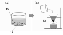
- the prepared carbon-containing material 11 of the precursor is immersed in a metal bath 12 having a freezing point lower than the melting point of the carbon-containing material 11 for a predetermined time.
- the metal bath 12 is controlled to a temperature lower than the minimum value of the liquidus temperature within the composition variation range from the carbon-containing material 11 until the main component other than carbon decreases to carbon.
- the metal bath 12 is a liquid within the composition variation range from Mn reduction to C from the phase diagram shown in FIG.
- the temperature is controlled to be lower than the minimum value of the phase line temperature 1231 ° C.
- the metal bath 12 is preferably set to 600 ° C. or higher.
- the immersion time in the metal bath 12 varies depending on the components of the metal bath 12 and the precursor carbon-containing material 11.
- a molten Bi or Ag melt is used as the metal bath 12
- Mn—C is used as the carbon-containing material 11.
- the system precursor takes about 5 to 10 minutes.
- the precursor and the molten metal are preferably stirred with a rod or the like.
- a melt of Bi or an alloy thereof is generally easy to oxidize, it is preferable to perform a decomponentation process using the metal bath 12 in an inert atmosphere such as argon or in a vacuum atmosphere.
- the unreacted precursor 14 Since there is a possibility that the unreacted precursor 14 remains in the vicinity of the surface of the molten metal, the unreacted precursor 14 adheres to the surface of the bulk porous carbon material 13 taken out from the metal bath 12. Resulting in. Therefore, as shown in FIG. 2B, the unreacted precursor 14 attached to the surface of the porous carbon material 13 is cleaned and removed using an ultrasonic cleaner or the like.
- the obtained porous carbon material 13 is put into an acid or alkaline aqueous solution 15 in order to selectively elute and remove only the adhering admixture.
- the aqueous solution 15 containing the porous carbon material 13 is a nitric acid aqueous solution.
- filtration or the like is performed to collect the porous carbon material 13 in the solid portion, which is then washed and dried. .
- a porous carbon material 13 having a desired shape from which carbon is the main component and from which the adhering admixture has been removed can be obtained.
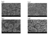
- FIGS. 4 (a) and 4 (b) Micrographs of the spherical MnC alloy thus obtained are shown in FIGS. 4 (a) and 4 (b). As shown in FIGS. 4A and 4B, it was confirmed that the obtained MnC alloy was spherical and the particle size was 100 ⁇ m or less.
- the obtained spherical MnC alloy was used as the carbon-containing material 11 to produce a spherical porous carbon material 13.
- a 800 ° C. Bi molten metal was used as the metal bath 12.
- 150 g of Bi having a purity of 99.99% (made by Wako Pure Chemical Industries, Ltd.) was filled into a graphite crucible, and the graphite crucible was filled with a high-frequency melting furnace (“VMF-I-I0. 5 special type ”) was inserted into the internal coil.
- the inside of the high-frequency melting furnace was depressurized to about 5 ⁇ 10 ⁇ 3 Pa, and then argon gas was introduced to increase the pressure in the furnace to about 80 kPa and heating was performed.
- FIGS. 4C and 4D show micrographs of the porous carbon member 13 thus obtained. As shown in FIGS. 4C and 4D, it was confirmed that a spherical and porous carbon member 13 was obtained. Further, the obtained porous carbon member 13 had 91% of pores having a size of 2 to 200 nm in the total pore volume, and a BET specific surface area of 128 m 2 / g.
- a sheet-like porous carbon member 13 was produced.
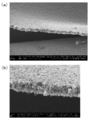
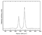
- a MnC thin film (Mn 85 C 15 thin film) of a precursor carbon-containing material 11 is formed on a Si substrate by sputtering, and the Si substrate is placed in a Bi metal bath 12 at 1100 ° C. Immersion for 10 minutes gave a sheet-like porous carbon member 13. Further, in order to remove the Mn component and Bi component remaining in the surroundings and in the minute gaps, the porous carbon member 13 was immersed in the nitric acid aqueous solution 3 for 3 hours, and then washed and dried. A scanning electron micrograph of the sheet-like porous carbon member 13 thus obtained is shown in FIG. 5, and a Raman spectrum is shown in FIG.
- Bi As a second manufacturing method, Bi was formed on a Si substrate, and a MnC thin film (Mn 85 C 15 thin film) of the precursor carbon-containing material 11 was formed thereon by sputtering. This was heated up to 1100 degreeC and hold
- MnC thin film Mn 85 C 15 thin film
- the entire Si substrate is cooled, and the carbon member 13 is immersed in the nitric acid aqueous solution 3 for 3 hours in order to remove the Mn component and Bi component remaining in the surroundings and in the minute gaps, and then washed and dried. Went.
- the precursor MnC thin film is disposed on the Bi thin film.
- the MnC thin film may be arranged in any arrangement as long as the MnC thin film comes into contact with the molten metal. Even if it is arranged between the Si substrate and the Bi thin film, it may be arranged so as to be sandwiched between the Bi thin films.
- the thickness of the sheet-like porous carbon member 13 can be controlled by the thickness of the precursor MnC thin film or the sputtering MnC film formation time, and the size is determined by the Si substrate. And the size of the precursor MnC thin film can be controlled.
- the porous carbon material 13 having a desired shape can be manufactured relatively easily and at a low cost only by controlling the temperature of the molten metal. Can do.
- the metal bath 12 is not limited to Bi, but Ag, Cu, Ga, Ge, Hg, In, Ir, Pb, Pt, Rh, Sb, Even if it is Sn or Zn, you may consist of the mixture which is an alloy which has at least one of these as a main component.
- the main component other than carbon of the precursor carbon-containing material 11 is not limited to Mn, but Al, B, Be, Ca, Ce, Cr, Dy, Er, Eu, Fe, Gd, Hf, and Ho.
- K La
- Li Lu
- Mg Mo
- Na Na
- Nb Nd
- Pr Pr
- Sc Se
- Si Sm
- Sr Ta
- Ti V, W, Zr, or a plurality thereof It may consist of an admixture containing
- Table 1 is examined based on each two-dimensional state diagram.
Landscapes
- Chemical & Material Sciences (AREA)
- Organic Chemistry (AREA)
- Engineering & Computer Science (AREA)
- Materials Engineering (AREA)
- Mechanical Engineering (AREA)
- Metallurgy (AREA)
- Inorganic Chemistry (AREA)
- Carbon And Carbon Compounds (AREA)
- Battery Electrode And Active Subsutance (AREA)
Priority Applications (5)
| Application Number | Priority Date | Filing Date | Title |
|---|---|---|---|
| US16/078,470 US11180374B2 (en) | 2016-03-04 | 2016-12-07 | Method for producing porous carbon material and spherical porous carbon material |
| EP16892721.8A EP3424878B1 (en) | 2016-03-04 | 2016-12-07 | Method for producing porous carbon material, and spherical porous carbon material |
| CN201680080841.5A CN108541250B (zh) | 2016-03-04 | 2016-12-07 | 多孔碳材料的制造方法以及球状的多孔碳材料 |
| KR1020187021739A KR20180118616A (ko) | 2016-03-04 | 2016-12-07 | 다공질 탄소 재료의 제조 방법 및 구상의 다공질 탄소 재료 |
| US16/802,722 US11377358B2 (en) | 2016-03-04 | 2020-02-27 | Method for producing porous carbon material |
Applications Claiming Priority (2)
| Application Number | Priority Date | Filing Date | Title |
|---|---|---|---|
| JP2016041914A JP6754198B2 (ja) | 2016-03-04 | 2016-03-04 | 多孔質炭素材料の製造方法 |
| JP2016-041914 | 2016-03-04 |
Related Child Applications (2)
| Application Number | Title | Priority Date | Filing Date |
|---|---|---|---|
| US16/078,470 A-371-Of-International US11180374B2 (en) | 2016-03-04 | 2016-12-07 | Method for producing porous carbon material and spherical porous carbon material |
| US16/802,722 Division US11377358B2 (en) | 2016-03-04 | 2020-02-27 | Method for producing porous carbon material |
Publications (1)
| Publication Number | Publication Date |
|---|---|
| WO2017149886A1 true WO2017149886A1 (ja) | 2017-09-08 |
Family
ID=59743741
Family Applications (1)
| Application Number | Title | Priority Date | Filing Date |
|---|---|---|---|
| PCT/JP2016/086357 Ceased WO2017149886A1 (ja) | 2016-03-04 | 2016-12-07 | 多孔質炭素材料の製造方法および球状の多孔質炭素材料 |
Country Status (6)
| Country | Link |
|---|---|
| US (2) | US11180374B2 (enExample) |
| EP (1) | EP3424878B1 (enExample) |
| JP (1) | JP6754198B2 (enExample) |
| KR (1) | KR20180118616A (enExample) |
| CN (1) | CN108541250B (enExample) |
| WO (1) | WO2017149886A1 (enExample) |
Families Citing this family (4)
| Publication number | Priority date | Publication date | Assignee | Title |
|---|---|---|---|---|
| JP6900149B2 (ja) * | 2016-03-04 | 2021-07-07 | 株式会社 東北テクノアーチ | 炭素複合材料 |
| CN112551509A (zh) * | 2019-09-25 | 2021-03-26 | 中国科学院金属研究所 | 一种制备纳米多孔碳或纳米球形碳的方法 |
| JP7093085B2 (ja) * | 2020-05-12 | 2022-06-29 | 株式会社 東北テクノアーチ | 多孔質炭素材料 |
| CN114823153B (zh) * | 2022-04-24 | 2023-11-03 | 华星先进科学技术应用研究(天津)有限公司 | 一种柔性钠离子电容器电极材料 |
Citations (8)
| Publication number | Priority date | Publication date | Assignee | Title |
|---|---|---|---|---|
| WO2005097674A1 (ja) * | 2004-03-30 | 2005-10-20 | Kureha Corporation | 球状炭素材の製造方法 |
| JP2006075708A (ja) * | 2004-09-09 | 2006-03-23 | Optonix Seimitsu:Kk | 球状超微粒子及びその製造方法 |
| WO2011078145A1 (ja) * | 2009-12-24 | 2011-06-30 | 東レ株式会社 | 炭素微粒子およびその製造方法 |
| WO2011092909A1 (ja) | 2010-01-28 | 2011-08-04 | 国立大学法人東北大学 | 金属部材の製造方法および金属部材 |
| JP4762424B2 (ja) | 2001-03-12 | 2011-08-31 | 昭和電工株式会社 | 活性炭、その製造方法及び該活性炭を用いた電気二重層キャパシタ |
| JP2011225430A (ja) | 2010-03-31 | 2011-11-10 | Toray Ind Inc | 多孔質構造を含有する炭素微粒子およびその製造方法 |
| JP2012101355A (ja) | 2011-12-28 | 2012-05-31 | Sony Corp | 多孔質炭素材料の製造方法 |
| JP2014522355A (ja) * | 2011-03-31 | 2014-09-04 | ビーエーエスエフ ソシエタス・ヨーロピア | 粒状多孔質炭素材料、リチウム電池に該粒状多孔質炭素材料を使用する方法 |
Family Cites Families (10)
| Publication number | Priority date | Publication date | Assignee | Title |
|---|---|---|---|---|
| US4957897A (en) * | 1988-01-29 | 1990-09-18 | Rohm And Haas Company | Carbonaceous adsorbents from pyrolyzed polysulfonated polymers |
| DE4328219A1 (de) * | 1993-08-21 | 1995-02-23 | Hasso Von Bluecher | Aktivkohlekügelchen aus Ionenaustauschern |
| US5714433A (en) * | 1996-02-06 | 1998-02-03 | Calgon Carbon Corporation | Activated carbon treated by carbon dioxide for the stabilization of treated water pH |
| JPH09328308A (ja) * | 1996-04-10 | 1997-12-22 | Mitsubishi Chem Corp | 活性炭及びその製造方法、並びにこれを用いたキャパシタ |
| CN1167807A (zh) * | 1996-05-31 | 1997-12-17 | 丸善石油化学株式会社 | 携带超细分散金属的含碳材料的制备方法 |
| US8591855B2 (en) | 2000-08-09 | 2013-11-26 | British American Tobacco (Investments) Limited | Porous carbons |
| EP1406834A1 (en) * | 2001-07-13 | 2004-04-14 | Kent State University | Imprinted mesoporous carbons and a method of manufacture thereof |
| US20070258879A1 (en) * | 2005-12-13 | 2007-11-08 | Philip Morris Usa Inc. | Carbon beads with multimodal pore size distribution |
| KR101195912B1 (ko) | 2010-09-17 | 2012-10-30 | 서강대학교산학협력단 | 구형의 다공성 탄소구조체 및 이의 제조 방법 |
| CN104925778B (zh) * | 2014-03-21 | 2017-05-03 | 中国科学院苏州纳米技术与纳米仿生研究所 | 碳纳米管微球及其制备方法与应用 |
-
2016
- 2016-03-04 JP JP2016041914A patent/JP6754198B2/ja active Active
- 2016-12-07 WO PCT/JP2016/086357 patent/WO2017149886A1/ja not_active Ceased
- 2016-12-07 EP EP16892721.8A patent/EP3424878B1/en active Active
- 2016-12-07 US US16/078,470 patent/US11180374B2/en active Active
- 2016-12-07 KR KR1020187021739A patent/KR20180118616A/ko not_active Withdrawn
- 2016-12-07 CN CN201680080841.5A patent/CN108541250B/zh active Active
-
2020
- 2020-02-27 US US16/802,722 patent/US11377358B2/en active Active
Patent Citations (8)
| Publication number | Priority date | Publication date | Assignee | Title |
|---|---|---|---|---|
| JP4762424B2 (ja) | 2001-03-12 | 2011-08-31 | 昭和電工株式会社 | 活性炭、その製造方法及び該活性炭を用いた電気二重層キャパシタ |
| WO2005097674A1 (ja) * | 2004-03-30 | 2005-10-20 | Kureha Corporation | 球状炭素材の製造方法 |
| JP2006075708A (ja) * | 2004-09-09 | 2006-03-23 | Optonix Seimitsu:Kk | 球状超微粒子及びその製造方法 |
| WO2011078145A1 (ja) * | 2009-12-24 | 2011-06-30 | 東レ株式会社 | 炭素微粒子およびその製造方法 |
| WO2011092909A1 (ja) | 2010-01-28 | 2011-08-04 | 国立大学法人東北大学 | 金属部材の製造方法および金属部材 |
| JP2011225430A (ja) | 2010-03-31 | 2011-11-10 | Toray Ind Inc | 多孔質構造を含有する炭素微粒子およびその製造方法 |
| JP2014522355A (ja) * | 2011-03-31 | 2014-09-04 | ビーエーエスエフ ソシエタス・ヨーロピア | 粒状多孔質炭素材料、リチウム電池に該粒状多孔質炭素材料を使用する方法 |
| JP2012101355A (ja) | 2011-12-28 | 2012-05-31 | Sony Corp | 多孔質炭素材料の製造方法 |
Also Published As
| Publication number | Publication date |
|---|---|
| US11180374B2 (en) | 2021-11-23 |
| JP2017154951A (ja) | 2017-09-07 |
| CN108541250B (zh) | 2022-04-19 |
| EP3424878B1 (en) | 2020-11-04 |
| US11377358B2 (en) | 2022-07-05 |
| JP6754198B2 (ja) | 2020-09-09 |
| US20190084834A1 (en) | 2019-03-21 |
| KR20180118616A (ko) | 2018-10-31 |
| EP3424878A1 (en) | 2019-01-09 |
| CN108541250A (zh) | 2018-09-14 |
| US20200198979A1 (en) | 2020-06-25 |
| EP3424878A4 (en) | 2019-01-09 |
Similar Documents
| Publication | Publication Date | Title |
|---|---|---|
| KR102003112B1 (ko) | 다공질 흑연의 제조 방법 및 다공질 흑연 | |
| US11377358B2 (en) | Method for producing porous carbon material | |
| JP6443584B2 (ja) | R−t−b系焼結磁石の製造方法 | |
| JP7093085B2 (ja) | 多孔質炭素材料 | |
| JP2009030090A (ja) | 金属粉末複合材等とその製造方法 | |
| KR20150062611A (ko) | 메탈폼의 제조방법, 이에 의해 제조된 메탈폼 및 상기 메탈폼으로 이루어지는 배기가스 정화 필터용 촉매 담체 | |
| JP6747670B2 (ja) | 金属部材の製造方法 | |
| KR101530727B1 (ko) | 밸브 금속 및 밸브 금속 아산화물로 이루어진 나노 크기 구조체 및 그 제조 방법 | |
| KR101755988B1 (ko) | 나노카본 강화 알루미늄 복합재 및 그 제조방법 | |
| CN108603248B (zh) | 碳复合材料的制造方法以及碳复合材料 | |
| JP2017160058A (ja) | カーボンオニオンの製造方法 | |
| JP6101897B2 (ja) | 焼成体の製造方法 | |
| JP2025507611A (ja) | 金属フォーム及び金属フォームを作製するための方法 | |
| JP5904648B2 (ja) | 複合金属ナノ粒子コロイド、複合金属ナノ粒子、複合金属ナノ粒子コロイドの製造方法、複合金属ナノ粒子の製造方法ならびに複合金属ナノ粒子コロイドの製造装置 | |
| KR101538101B1 (ko) | Zr을 포함하는 다공체의 제조방법 | |
| JP2016034640A (ja) | 複合金属ナノ粒子コロイド、複合金属ナノ粒子、複合金属ナノ粒子コロイドの製造方法、複合金属ナノ粒子の製造方法ならびに複合金属ナノ粒子コロイドの製造装置 | |
| JPH0243868Y2 (enExample) | ||
| JP2010150589A (ja) | 二元金属ナノ粒子コロイド、二元金属ナノ粒子、二元金属ナノ粒子コロイドの製造方法および二元金属ナノ粒子の製造方法 |
Legal Events
| Date | Code | Title | Description |
|---|---|---|---|
| ENP | Entry into the national phase |
Ref document number: 20187021739 Country of ref document: KR Kind code of ref document: A |
|
| NENP | Non-entry into the national phase |
Ref country code: DE |
|
| WWE | Wipo information: entry into national phase |
Ref document number: 2016892721 Country of ref document: EP |
|
| ENP | Entry into the national phase |
Ref document number: 2016892721 Country of ref document: EP Effective date: 20181004 |
|
| 121 | Ep: the epo has been informed by wipo that ep was designated in this application |
Ref document number: 16892721 Country of ref document: EP Kind code of ref document: A1 |