WO2017138571A1 - 光コネクタフェルール及び光接続構造 - Google Patents
光コネクタフェルール及び光接続構造 Download PDFInfo
- Publication number
- WO2017138571A1 WO2017138571A1 PCT/JP2017/004609 JP2017004609W WO2017138571A1 WO 2017138571 A1 WO2017138571 A1 WO 2017138571A1 JP 2017004609 W JP2017004609 W JP 2017004609W WO 2017138571 A1 WO2017138571 A1 WO 2017138571A1
- Authority
- WO
- WIPO (PCT)
- Prior art keywords
- optical
- spacer
- optical connector
- ferrule
- optical fiber
- Prior art date
- Legal status (The legal status is an assumption and is not a legal conclusion. Google has not performed a legal analysis and makes no representation as to the accuracy of the status listed.)
- Ceased
Links
Images



Classifications
-
- G—PHYSICS
- G02—OPTICS
- G02B—OPTICAL ELEMENTS, SYSTEMS OR APPARATUS
- G02B6/00—Light guides; Structural details of arrangements comprising light guides and other optical elements, e.g. couplings
- G02B6/24—Coupling light guides
- G02B6/36—Mechanical coupling means
- G02B6/38—Mechanical coupling means having fibre to fibre mating means
- G02B6/3807—Dismountable connectors, i.e. comprising plugs
- G02B6/381—Dismountable connectors, i.e. comprising plugs of the ferrule type, e.g. fibre ends embedded in ferrules, connecting a pair of fibres
- G02B6/3818—Dismountable connectors, i.e. comprising plugs of the ferrule type, e.g. fibre ends embedded in ferrules, connecting a pair of fibres of a low-reflection-loss type
-
- G—PHYSICS
- G02—OPTICS
- G02B—OPTICAL ELEMENTS, SYSTEMS OR APPARATUS
- G02B6/00—Light guides; Structural details of arrangements comprising light guides and other optical elements, e.g. couplings
- G02B6/24—Coupling light guides
- G02B6/36—Mechanical coupling means
- G02B6/38—Mechanical coupling means having fibre to fibre mating means
- G02B6/3807—Dismountable connectors, i.e. comprising plugs
- G02B6/381—Dismountable connectors, i.e. comprising plugs of the ferrule type, e.g. fibre ends embedded in ferrules, connecting a pair of fibres
- G02B6/3818—Dismountable connectors, i.e. comprising plugs of the ferrule type, e.g. fibre ends embedded in ferrules, connecting a pair of fibres of a low-reflection-loss type
- G02B6/3822—Dismountable connectors, i.e. comprising plugs of the ferrule type, e.g. fibre ends embedded in ferrules, connecting a pair of fibres of a low-reflection-loss type with beveled fibre ends
-
- G—PHYSICS
- G02—OPTICS
- G02B—OPTICAL ELEMENTS, SYSTEMS OR APPARATUS
- G02B6/00—Light guides; Structural details of arrangements comprising light guides and other optical elements, e.g. couplings
- G02B6/24—Coupling light guides
- G02B6/36—Mechanical coupling means
- G02B6/38—Mechanical coupling means having fibre to fibre mating means
- G02B6/3807—Dismountable connectors, i.e. comprising plugs
- G02B6/381—Dismountable connectors, i.e. comprising plugs of the ferrule type, e.g. fibre ends embedded in ferrules, connecting a pair of fibres
- G02B6/3826—Dismountable connectors, i.e. comprising plugs of the ferrule type, e.g. fibre ends embedded in ferrules, connecting a pair of fibres characterised by form or shape
-
- G—PHYSICS
- G02—OPTICS
- G02B—OPTICAL ELEMENTS, SYSTEMS OR APPARATUS
- G02B6/00—Light guides; Structural details of arrangements comprising light guides and other optical elements, e.g. couplings
- G02B6/24—Coupling light guides
- G02B6/36—Mechanical coupling means
- G02B6/38—Mechanical coupling means having fibre to fibre mating means
- G02B6/3807—Dismountable connectors, i.e. comprising plugs
- G02B6/3873—Connectors using guide surfaces for aligning ferrule ends, e.g. tubes, sleeves, V-grooves, rods, pins, balls
- G02B6/3882—Connectors using guide surfaces for aligning ferrule ends, e.g. tubes, sleeves, V-grooves, rods, pins, balls using rods, pins or balls to align a pair of ferrule ends
-
- G—PHYSICS
- G02—OPTICS
- G02B—OPTICAL ELEMENTS, SYSTEMS OR APPARATUS
- G02B6/00—Light guides; Structural details of arrangements comprising light guides and other optical elements, e.g. couplings
- G02B6/24—Coupling light guides
- G02B6/36—Mechanical coupling means
- G02B6/38—Mechanical coupling means having fibre to fibre mating means
- G02B6/3807—Dismountable connectors, i.e. comprising plugs
- G02B6/3873—Connectors using guide surfaces for aligning ferrule ends, e.g. tubes, sleeves, V-grooves, rods, pins, balls
- G02B6/3885—Multicore or multichannel optical connectors, i.e. one single ferrule containing more than one fibre, e.g. ribbon type
Definitions
- the present invention relates to an optical connector ferrule and an optical connection structure.
- Patent Document 1 discloses a ferrule used for an optical connector for connecting multi-core optical fibers.
- the ferrule is provided in front of the inner surface at the end surface, a plurality of holes for holding the plurality of optical fibers, an inner surface that contacts the tip portions of the plurality of optical fibers to position the tip portions, and A concave portion and a lens integrally formed in the concave portion are provided.
- a PC (Physical Contact) method is generally known as a method for connecting connectors between optical fibers.
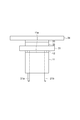
- 8A and 8B are side sectional views showing an example of the structure of a PC type ferrule.
- FIG. 8A shows a state before connection
- FIG. 8B shows a connection state.
- the ferrule 100 has a cylindrical appearance, and has a hole 102 for holding the optical fiber 120 on the central axis.
- the optical fiber 120 is inserted into the hole 102, and the tip portion slightly protrudes to the outside on the tip surface 104 of the ferrule 100.
- the optical fibers 120 are efficiently optically coupled to each other by pressing the distal end portion of the optical fiber 120 in physical contact with the distal end portion of the connection partner connector (FIG. 8B).
- Such a system is mainly used when connecting single-core optical fibers.
- this method has the following problems. That is, if a connection is made with foreign matter attached to the ferrule end face, the foreign matter will adhere to the ferrule end face by the pressing force. In order to remove the adhered foreign matter, it is necessary to use a contact-type cleaner, and in order to prevent the foreign matter from sticking, it is necessary to frequently perform cleaning. In addition, when a plurality of optical fibers are connected at the same time, a predetermined pressing force is required for each optical fiber, so that a larger force is required for connection as the number of optical fibers increases.
- FIG. 9 is a side sectional view schematically showing an example of the structure of such a ferrule.
- the ferrule 200 includes a plurality of holes 202 for holding a plurality of optical fibers 120, an inner surface 204 that contacts the distal end portions of the plurality of optical fibers and positions the distal end portions, and an inner surface 204 at the end surface 205.
- a lens 208 provided in front of the lens.
- the position of the lens 208 in addition to the optical fiber 120 needs to be accurately aligned. Accordingly, the number of parts requiring alignment work increases, and the positional error (tolerance) allowed for each part becomes severe, so that the alignment process becomes complicated and takes a long time.
- An optical connector ferrule includes a flat ferrule end face that faces a counterpart optical connector, and a main body having an optical fiber holding hole that is open at the ferrule end face and into which an optical fiber is inserted and held.
- a spacer that is joined to the main body and at least a part thereof is disposed on the ferrule end face, defines a distance between the ferrule end face and the counterpart optical connector, and has an opening that allows an optical path extending from the optical fiber to pass therethrough.
- the present invention it is easy to clean the ferrule end face, and even when a plurality of optical fibers are simultaneously connected, a large force is not required for connection, and an optical connector ferrule that can be easily aligned can be provided. .
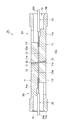
- FIG. 1 is a side sectional view showing a configuration of an optical connector ferrule according to an embodiment of the present invention.
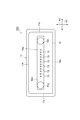
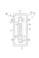
- FIG. 2 is a front view of the optical connector ferrule viewed from the connection direction.
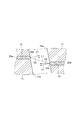
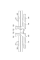
- FIG. 3 is a side sectional view showing an optical connection structure including an optical connector including the optical connector ferrule of one embodiment and a counterpart optical connector.
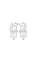
- FIG. 4 is an enlarged cross-sectional view showing a portion D shown in FIG.
- FIG. 5A schematically shows a step of joining a spacer to the main body as an example of the method for manufacturing the optical connector ferrule of the present embodiment.
- FIG. 5B schematically shows a process of joining the spacer to the main body as an example of the manufacturing method of the optical connector ferrule of the present embodiment.
- FIG. 5A schematically shows a step of joining a spacer to the main body as an example of the method for manufacturing the optical connector ferrule of the present embodiment.
- FIG. 5B schematically shows a process of joining the spacer
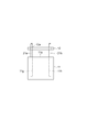
- FIG. 6 is a front view of the optical connector ferrule according to the first modification.
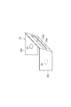
- FIG. 7A is a plan view of a developed spacer according to a second modification.
- FIG. 7B is a perspective view of a spacer according to a second modification.
- FIG. 8A is a side sectional view showing an example of the structure of a PC type ferrule.
- FIG. 8B is a side sectional view showing an example of the structure of a PC type ferrule.
- FIG. 9 is a side sectional view schematically showing an example of a ferrule structure.
- An optical connector ferrule includes a flat ferrule end face that faces a counterpart optical connector, and a main body having an optical fiber holding hole that is open at the ferrule end face and into which an optical fiber is inserted and held.
- a spacer that is joined to the main body and at least a part thereof is disposed on the ferrule end face, defines a distance between the ferrule end face and the counterpart optical connector, and has an opening that allows an optical path extending from the optical fiber to pass therethrough.
- a spacer for defining the distance from the counterpart optical connector is provided on the ferrule end face.
- interval can be easily provided between a ferrule end surface and the other party optical connector. Therefore, a non-contact optical connection structure can be realized, and the ferrule end face can be easily cleaned (or need not be cleaned).
- a plurality of optical fibers can be connected simultaneously without requiring a large force for connection.
- the optical fiber holding hole is opened at the ferrule end face, the front end face of the optical fiber is exposed at the ferrule end face, and is optically coupled without passing through the optical fiber of the counterpart optical connector. Therefore, the number of optical members present in the optical path can be reduced, and optical connection loss can be suppressed.
- the main body portion further includes a pair of guide holes which are opened at positions where the optical fiber holding holes are sandwiched on the end surfaces of the ferrules and into which the guide pins are respectively inserted, and the axial direction of the pair of guide holes
- the inner edge of the opening may be in contact with the edge of the guide hole as viewed from the top.
- the opening of the spacer is passed through the jig with a rod-shaped jig such as a guide pin inserted into the pair of guide holes, and the inner edge of the opening is inserted into the jig.
- the spacers are disposed on the ferrule end face while being in contact with each other. Thereby, a spacer can be easily and accurately positioned with respect to a main-body part.
- the spacer may be made of resin or metal. Accordingly, it is possible to realize a spacer that can be easily joined to the main body and can accurately define the distance from the counterpart optical connector.
- the spacer may be bonded to the main body portion with an adhesive.
- the spacer and the main body may be made of resin, and the spacer may be welded to the main body. With any one of these configurations, the spacer can be easily joined to the main body.
- the spacer has a first portion facing the ferrule end surface and a second portion extending along the side surface of the main body, and the first portion is not joined to the ferrule end surface,
- the two parts may be joined to the side.
- the thickness of the spacer may be 100 ⁇ m or less.
- the optical fiber holding hole may have a plurality of holes.
- a plurality of optical fibers can be simultaneously connected without requiring a large force for connection.
- FIG. 1 is a side sectional view showing a configuration of an optical connector ferrule 10A according to an embodiment of the present invention, and shows a cross section along a connection direction A1 (that is, an optical axis direction of an optical fiber).
- FIG. 2 is a front view of the optical connector ferrule 10A viewed from the connection direction A1.
- the optical connector ferrule 10 ⁇ / b> A includes a main body 11 and a spacer 12.
- the main body 11 has a substantially rectangular parallelepiped appearance and is made of, for example, resin.
- the main body 11 has a flat ferrule end surface 11a provided on one end side in the connection direction A1 and facing the counterpart optical connector, and a rear end surface 11b provided on the other end side.
- the main body 11 has a pair of side surfaces 11c and 11d extending along the connection direction A1, a bottom surface 11e, and an upper surface 11f.
- the rear end face 11b is formed with an introduction hole 15 for receiving a plurality of optical fibers collectively. These optical fibers are introduced in the form of, for example, a 0.25 mm strand, a 0.9 mm core, or a tape core.
- the main body 11 further has a plurality of optical fiber holding holes 13.
- the plurality of optical fiber holding holes 13 penetrate from the introduction hole 15 to the ferrule end face 11a, and their front ends are open at the ferrule end face 11a.
- the openings of the plurality of optical fiber holding holes 13 are arranged in a line along the direction A2 intersecting the connection direction A1 on the ferrule end face 11a. These optical fiber holding holes 13 hold the inserted optical fiber.
- the main body 11 further has a pair of guide holes 11g and 11h.
- a pair of guide pins for fixing the relative positions of the optical connector ferrule 10A and the optical connector ferrule of the counterpart optical connector are inserted into the guide holes 11g and 11h.
- the pair of guide holes 11g and 11h extend with the connection direction A1 as the central axis, and are aligned along the direction A2. Further, the guide holes 11g and 11h are opened at the ferrule end face 11a, and these openings are respectively provided at positions sandwiching the plurality of optical fiber holding holes 13 (in other words, both ends of the row of the optical fiber holding holes 13). ing.
- the spacer 12 is a film-like (thin film-like) member, and at least a part of the spacer 12 is disposed on the ferrule end surface 11a, and is sandwiched between the ferrule end surface 11a and the mating optical connector. Defines the distance from the ferrule end face of the mating optical connector. At least a part of the spacer 12 is joined to any part of the main body 11. Joining of the spacer 12 and the main body 11 is performed by, for example, adhesion via an adhesive or welding (laser welding or the like). When the material is different between the spacer 12 and the main body 11 (for example, metal and resin), an adhesive is used, but when the material is the same between the spacer 12 and the main body 11 (for example, between resins).
- the spacer 12 may be peeled off from the main body part 11 at the time of temperature change. This is because reliability increases.
- the spacer 12 is provided only on the ferrule end surface 11a, and the spacer 12 is joined to the ferrule end surface 11a.
- the spacer 12 has an opening 12a formed on the ferrule end face 11a.
- the opening 12a has a plurality of optical paths extending between the respective front end surfaces of the plurality of optical fibers held by the plurality of optical fiber holding holes 13 and the respective front end surfaces of the plurality of optical fibers of the counterpart optical connector. In order to pass through, the openings of the plurality of optical fiber holding holes 13 are exposed.
- the opening 12a is formed with the direction A2 as the longitudinal direction.
- the length of the opening 12a in the direction A2 is, for example, 5.31 mm
- the width of the direction A3 that intersects the direction A2 is, for example, 0.71 mm.
- the outer dimension of the spacer 12 is the same as or smaller than the outer dimension of the ferrule end surface 11a. Thereby, peeling of the spacer 12 resulting from the catching to the peripheral part of the spacer 12 can be prevented.
- the thickness of the spacer 12 is, for example, 5 ⁇ m or more. Moreover, the thickness of the spacer 12 is 100 micrometers or less, for example, More preferably, it is 25 micrometers or less. Thereby, the space
- the constituent material of the spacer 12 is not particularly limited, and various materials can be used. However, it is preferable that the spacer 12 is made of resin (for example, polyphenylene sulfide (PPS)) or metal.
- PPS polyphenylene sulfide
- the inner edge of the opening 12a of the spacer 12 is in contact with the edge of the guide holes 11g and 11h when viewed from the axial direction of the guide holes 11g and 11h (that is, the connection direction A1).
- both of the pair of inner edges particularly along the direction A2 of the opening 12a are in contact with the edges of the guide holes 11g and 11h.
- “in contact with the edge” means that part of the guide holes 11g and 11h substantially overlaps (coincides with) the edge as viewed from the axial direction. Therefore, when the guide pin is inserted into the guide holes 11g and 11h, the outer peripheral surface of the guide pin and the inner edge of the opening 12a come into contact with each other.
- FIG. 3 is a side sectional view showing an optical connection structure 1A including an optical connector 2A including the optical connector ferrule 10A of the present embodiment and a counterpart optical connector 2B.
- the optical connector 2A further includes a plurality of optical fibers 20a in addition to the optical connector ferrule 10A.
- the counterpart optical connector 2B includes a main body 11 as an optical connector ferrule and a plurality of optical fibers 20a.
- the ferrule end surface 11a of the main body portion 11 of the optical connector 2A and the ferrule end surface 11a of the main body portion 11 of the counterpart optical connector 2B face each other.
- the plurality of optical fibers 20a extend along the connection direction A1.
- Each optical fiber 20a is covered with a resin coating 20b to constitute an optical fiber core wire 20, and a part of the optical fiber 20a is exposed by removing the resin coating 20b from the middle in the connection direction A1 to the tip. ing.
- These optical fibers 20a are inserted and held in the plurality of optical fiber holding holes 13 of the main body 11, respectively.
- the spacer 12 is sandwiched between the ferrule end surface 11a of the optical connector 2A and the ferrule end surface 11a of the counterpart optical connector 2B, thereby defining a distance between these ferrule end surfaces 11a. Therefore, the surface of the spacer 12 contacts the ferrule end surface 11a of the counterpart optical connector 2B.
- the optical fiber 20a on the optical connector 2A side and the optical fiber 20a on the counterpart optical connector 2B side are optically coupled through the opening 12a of the spacer 12.
- FIG. 4 is an enlarged cross-sectional view of a portion D shown in FIG.
- the end face 20c of each optical fiber 20a is exposed at the ferrule end face 11a, and is preferably flush with the ferrule end face 11a.
- the normal direction V1 of the tip surface 20c of the optical fiber 20a and the ferrule end surface 11a is inclined with respect to the optical axis direction V2 of the optical fiber 20a. Thereby, the reflected return light in the front end surface 20c is reduced.
- the optical path L1 of the light emitted from the distal end surface 20c of the optical fiber 20a is refracted in the direction opposite to the inclination direction of the distal end surface 20c at the distal end surface 20c. Therefore, the central axis of the optical fiber 20a of the optical connector 2A and the central axis of the optical fiber 20a of the counterpart optical connector 2B are shifted from each other in the refraction direction.
- the distal end surface 20c of the optical fiber 20a on the optical connector 2A side and the distal end surface 20c of the optical fiber 20a on the counterpart optical connector 2B side do not pass through an optical element such as a lens or a refractive index matching agent (air). (Via only) is directly photocoupled. Therefore, the light emitted from the front end surface 20c of one optical connector is incident on the front end surface 20c of the other optical connector while having a slight spread.
- an optical element such as a lens or a refractive index matching agent (air).
- 5A and 5B schematically show a process of joining the spacer 12 to the main body 11 as an example of a method for manufacturing the optical connector ferrule 10A of the present embodiment.
- the spacer 12 and the main body 11 are made of resin (preferably made of the same material).
- rod-like jigs 21 a and 21 b are inserted into the guide holes 11 g and 11 h of the main body 11.
- Guide pins may be used as the rod-shaped jigs 21a and 21b.
- the rod-shaped jigs 21 a and 21 b are passed through the opening 12 a of the spacer 12, and the spacer 12 is moved onto the ferrule end surface 11 a of the main body 11.
- the inner edge of the opening 12a is in contact with the edges of the guide holes 11g and 11h when viewed from the connection direction A1
- the inner edge of the opening 12a is in contact with the outer peripheral surfaces of the rod-shaped jigs 21a and 21b.
- the relative positions of the rod-shaped jigs 21a and 21b and the spacer 12, and the relative positions of the main body 11 and the spacer 12 are easily and accurately positioned.
- a plate-shaped jig 31, an elastic jig 32, an optical mask 33, and a plate-shaped jig 34 are placed on the spacer 12 in this order.
- the spacer 12 and the ferrule end surface 11a of the main body 11 are welded to each other by irradiating laser light from above while suppressing the positional deviation of the spacer 12 by applying pressure with the plate-shaped jig 34.
- the elastic jig 32 absorbs the relative inclination between the plate-like jig 31 and the plate-like jig 34.
- the optical mask 33 protects at least the optical fiber holding hole 13 from laser light irradiation.
- the optical mask 33 protects a region that is narrower than the opening 12a of the spacer 12 and can cover all the optical fiber holding holes 13 from the irradiation of the laser beam.
- the plate-shaped jig 31, the elastic jig 32, and the plate-shaped jig 34 are configured by members that transmit at least the wavelength of the laser beam.
- the plate-shaped jig 31 is an acrylic plate having a thickness of 2 mm, for example.
- the elastic jig 32 is a silicone film having a thickness of 2 mm.
- the plate-shaped jig 34 is an acrylic plate having a thickness of 10 mm, for example.
- the optical connector ferrule 10A of the present embodiment described above a spacer 12 that defines a distance from the counterpart optical connector 2B is provided on the ferrule end surface 11a.
- interval can be easily provided between the ferrule end surface 11a and the other party optical connector 2B.
- the optical fiber holding hole 13 is opened at the ferrule end surface 11a, the front end surface 20c of the optical fiber 20a is exposed at the ferrule end surface 11a, and the optical fiber 20a of the counterpart optical connector 2B and the lens are interposed. Without being optically coupled.
- a plurality of optical fibers 20a can be connected simultaneously without requiring a large force for connection. Furthermore, as described above, since the optical fiber 20a is optically coupled to the optical fiber 20a of the counterpart optical connector 2B without using a lens, the number of optical members existing in the optical path can be reduced, and optical connection loss can be suppressed. Can do. Furthermore, the alignment process can be facilitated, the number of manufacturing processes can be reduced, and the cost can be kept low.
- the spacer 12 may be joined after the ferrule end surface 11a and the front end surface 20c are polished, and such a problem does not occur.
- the spacer 12 may be made of resin or metal. Thereby, the spacer 12 which can be easily joined to the main body 11 and can accurately define the distance from the counterpart optical connector 2B can be realized.
- the spacer 12 and the main body 11 are made of resin
- the spacer 12 may be welded to the main body 11.
- the spacer 12 can be easily joined to the main body 11.
- the thickness of the spacer 12 may be 100 ⁇ m or less.
- a plurality of optical fiber holding holes 13 may be provided. As described above, according to the optical connector ferrule 10A of the present embodiment, a plurality of optical fibers 20a can be connected at the same time without requiring a large force for connection.
- the normal directions of the tip surface 20c and the ferrule end surface 11a of the optical fiber 20a are inclined with respect to the optical axis direction of the optical fiber 20a (see FIG. 4). Thereby, the reflected return light in the front end surface 20c of the optical fiber 20a can be reduced.
- the spacer 12 and the main body 11 are separate members, the inclined ferrule end surface 11a and the front end surface 20c of the optical fiber 20a can be easily formed by polishing or the like.
- FIG. 6 is a front view of an optical connector ferrule 10B according to a first modification.
- the optical connector ferrule 10 ⁇ / b> B of this modification includes a main body portion 11 ⁇ / b> B and a spacer 22.
- the main body 11B has a larger number of optical fiber holding holes 13 than in the above embodiment.
- These optical fiber holding holes 13 constitute a plurality of rows (three rows in the figure) of optical fiber holding holes. That is, in each row, a plurality of optical fiber holding holes 13 are arranged along the direction A2, and these rows are arranged in the direction A3.
- the structure of the main-body part 11B other than this is the same as that of the main-body part 11 of the said embodiment.
- the spacer 22 has an opening 22a.
- the width of the opening 22a in the direction A3 is larger than the width of the opening 12a (see FIG. 2) in the same direction. Since the inner edges of both ends of the opening 22a in the direction A2 overlap with the edges of the guide holes 11g and 11h, the width of the both ends in the direction A3 is equal to the width of the opening 12a. As a result, a step 22b is provided on the inner edge of the opening 22a.
- the structure of the spacer 22 other than this is the same as that of the spacer 12 of the said embodiment.
- the shape of the opening of the spacer is not limited to the above embodiment, and may be various shapes such as the shape of the opening 22a of the present modification.
- the opening of the spacer does not necessarily have to be closed, and a part of the opening may reach the outer edge of the spacer. Regardless of the shape of the opening, the effects of the above-described embodiment can be suitably obtained.
- FIG. 7A and 7B show the configuration of the spacer 23 according to the second modification.
- 7A is a plan view in which the spacer 23 is developed
- FIG. 7B is a perspective view of the spacer 23.
- the spacer 23 of this modification has a first portion 23b that faces the ferrule end surface 11a, and a pair of second portions 23c that extend along the side surfaces 11c and 11d (see FIG. 2) of the main body portion 11.
- the opening 23a is formed in the first portion 23b and has the same shape as the opening 12a of the above embodiment.
- the first portion 23 b is not joined to the ferrule end surface 11 a
- the second portion 23 c is joined to the side surfaces 11 c and 11 d of the main body 11.
- the pair of second portions 23c may be bonded to the side surfaces 11c and 11d by an adhesive 24, or may be welded to the side surfaces 11c and 11d by laser light, respectively.
- the spacer 23 is not bonded to the ferrule end surface 11a, it is possible to avoid the adhesive from flowing into the optical fiber holding hole 13.
- Such a configuration is particularly suitable when the spacer 23 and the main body 11 are made of different materials (for example, the spacer 23 is a metal and the main body 11 is a resin). In such a case, the spacer 23 and the main body 11 cannot be welded and need to be bonded.
- the optical connector ferrule according to the present invention is not limited to the above-described embodiment, and various other modifications are possible.
- the above-described embodiments and modification examples may be combined with each other according to necessary purposes and effects.
- the clearance gap between ferrule end surfaces is satisfy
- the present invention is applied to the multi-core optical connector in the above-described embodiment, it can also be applied to a single-core optical connector.
- the normal direction of the optical fiber tip surface and the ferrule end surface is inclined with respect to the optical axis direction of the optical fiber. However, these normal direction and optical axis direction may coincide with each other. .
Landscapes
- Physics & Mathematics (AREA)
- General Physics & Mathematics (AREA)
- Optics & Photonics (AREA)
- Mechanical Coupling Of Light Guides (AREA)
- Optical Couplings Of Light Guides (AREA)
Abstract
光コネクタフェルールは、本体部とスペーサとを備える。本体部は、相手側光コネクタと対向する平坦なフェルール端面と、フェルール端面において開口しており光ファイバが挿入及び保持される光ファイバ保持孔とを有する。スペーサは、本体部に接合されるとともに少なくとも一部がフェルール端面上に配置される。スペーサは、フェルール端面と相手側光コネクタとの間隔を規定し光ファイバから延びる光路を通過させる開口部を有する。
Description
本発明は、光コネクタフェルール及び光接続構造に関するものである。
特許文献1には、多芯光ファイバ同士を接続する光コネクタに用いられるフェルールが開示されている。このフェルールは、複数本の光ファイバを保持するための複数の孔と、複数本の光ファイバの先端部と当接して該先端部の位置決めを行う内面と、端面において内面の前方に設けられた凹部と、凹部に一体形成されたレンズとを備える。
光ファイバ同士のコネクタ接続の方式として、一般的にPC(Physical Contact)方式が知られている。図8A及び図8Bは、PC方式のフェルールの構造の一例を示す側断面図である。図8Aは接続前の状態を示し、図8Bは接続している状態を示す。このフェルール100は、円柱状の外観を有しており、光ファイバ120を保持するための孔102を中心軸線上に有する。光ファイバ120は、孔102に挿通され、フェルール100の先端面104において先端部が外部に僅かに突出する。このPC方式では、光ファイバ120の先端部を、接続相手側コネクタの同先端部と物理的に接触させて押圧することにより(図8B)、光ファイバ120同士を効率的に光結合させる。このような方式は、主に単心光ファイバ同士を接続する際に用いられる。
しかしながら、このような方式には次の問題がある。すなわち、フェルール端面に異物が付着した状態で接続してしまうと、押圧力によってフェルール端面に異物が密着してしまう。密着した異物を取り除くためには接触式のクリーナを使用する必要があり、また、異物の密着を防ぐためには頻繁に清掃を行う必要がある。また、複数本の光ファイバを同時に接続する場合、1本毎に所定の押圧力が要求されるので、光ファイバの本数が多くなるほど接続に大きな力が必要となる。
上記の問題に対し、例えば特許文献1に記載されたように、互いに接続される光ファイバの先端面の間に間隔を設け、該間隔部分にレンズを配置したものがある。図9は、そのようなフェルールの構造の一例を模式的に示す側断面図である。このフェルール200は、複数本の光ファイバ120を保持するための複数の孔202と、複数本の光ファイバの先端部と当接して該先端部の位置決めを行う内面204と、端面205において内面204の前方に設けられたレンズ208とを備える。しかしながら、このような構造では、光ファイバ120に加えてレンズ208の位置も正確に調芯される必要がある。従って、調芯作業を要する部品点数が増し、各部品に許容される位置誤差(トレランス)が厳しくなるので、調芯工程が複雑化・長時間化してしまう。
本発明は、フェルール端面の清掃が容易であり、複数本の光ファイバを同時に接続する場合であっても接続に大きな力を必要とせず、調芯作業が容易な光コネクタフェルールを提供することを目的とする。
本発明の一実施形態に係る光コネクタフェルールは、相手側光コネクタと対向する平坦なフェルール端面、及びフェルール端面において開口しており光ファイバが挿入及び保持される光ファイバ保持孔を有する本体部と、本体部に接合されるとともに少なくとも一部がフェルール端面上に配置され、該フェルール端面と相手側光コネクタとの間隔を規定し、光ファイバから延びる光路を通過させる開口部を有するスペーサと、を備える。
本発明によれば、フェルール端面の清掃が容易であり、複数本の光ファイバを同時に接続する場合であっても接続に大きな力を必要とせず、調芯作業が容易な光コネクタフェルールを提供できる。
[本願発明の実施形態の説明]
最初に、本発明の実施形態の内容を列記して説明する。本発明の一実施形態に係る光コネクタフェルールは、相手側光コネクタと対向する平坦なフェルール端面、及びフェルール端面において開口しており光ファイバが挿入及び保持される光ファイバ保持孔を有する本体部と、本体部に接合されるとともに少なくとも一部がフェルール端面上に配置され、該フェルール端面と相手側光コネクタとの間隔を規定し、光ファイバから延びる光路を通過させる開口部を有するスペーサと、を備える。
最初に、本発明の実施形態の内容を列記して説明する。本発明の一実施形態に係る光コネクタフェルールは、相手側光コネクタと対向する平坦なフェルール端面、及びフェルール端面において開口しており光ファイバが挿入及び保持される光ファイバ保持孔を有する本体部と、本体部に接合されるとともに少なくとも一部がフェルール端面上に配置され、該フェルール端面と相手側光コネクタとの間隔を規定し、光ファイバから延びる光路を通過させる開口部を有するスペーサと、を備える。
上記の光コネクタフェルールでは、相手側光コネクタとの間隔を規定するスペーサが、フェルール端面上に設けられている。これにより、フェルール端面と相手側光コネクタとの間に所望の間隔を容易に設けることができる。従って、非接触の光接続構造を実現し、フェルール端面の清掃を容易に(或いは清掃不要に)することができる。また、PC方式と異なり、接続に大きな力を必要とせずに、複数本の光ファイバを同時に接続することができる。更には、光ファイバ保持孔がフェルール端面において開口しているので、光ファイバの先端面がフェルール端面において露出し、相手側光コネクタの光ファイバとレンズを介さずに光結合されることとなる。従って、光路に存在する光学部材の数を少なくでき、光接続損失を抑えることができる。
上記の光コネクタフェルールにおいては、フェルール端面において光ファイバ保持孔を挟む位置にそれぞれ開口しておりガイドピンがそれぞれ挿入される一対のガイド孔を本体部が更に有し、一対のガイド孔の軸線方向から見て開口部の内縁がガイド孔の縁に接してもよい。この場合、当該光コネクタフェルールを製造する際に、一対のガイド孔にガイドピン等の棒状の治具を差し込んだ状態でスペーサの開口部を該治具に通し、開口部の内縁を該治具に接触させながらスペーサをフェルール端面上に配置することとなる。これにより、本体部に対してスペーサを容易に且つ精度良く位置決めできる。
上記の光コネクタフェルールにおいて、スペーサは樹脂製または金属製であってもよい。これにより、本体部に容易に接合でき且つ相手側光コネクタとの間隔を精度良く規定することが可能なスペーサを実現できる。
上記の光コネクタフェルールにおいて、スペーサは接着剤により本体部に接着されてもよい。或いは、上記の光コネクタフェルールにおいて、スペーサ及び本体部が樹脂製であり、スペーサが本体部に溶着されてもよい。これらの何れかの構成によって、スペーサを本体部に容易に接合できる。
上記の光コネクタフェルールにおいて、スペーサは、フェルール端面と対向する第1部分と、本体部の側面に沿って延びる第2部分とを有し、第1部分はフェルール端面に接合されておらず、第2部分は側面に接合されてもよい。これにより、スペーサとの接合によるフェルール端面への影響(例えば、光ファイバ保持孔への接着剤の流れ込みなど)を回避することができる。
上記の光コネクタフェルールにおいて、スペーサの厚さは100μm以下であってもよい。このような薄いスペーサによってフェルール端面と相手側光コネクタとの間隔を規定することにより、当該光コネクタフェルールに挿入される光ファイバと相手側光コネクタの光ファイバとの距離を短くし、レンズを介さない構成にもかかわらず低い結合損失でもってこれらの光ファイバ同士を接続することができる。
また、上記の光コネクタフェルールでは、光ファイバ保持孔は複数の孔を有してもよい。前述したように、上記の光コネクタフェルールによれば、接続に大きな力を必要とせずに、複数本の光ファイバを同時に接続することができる。
[本願発明の実施形態の詳細]
本発明の実施形態に係る光コネクタフェルールの具体例を、以下に図面を参照しつつ説明する。なお、本発明はこれらの例示に限定されるものではなく、特許請求の範囲によって示され、特許請求の範囲と均等の意味及び範囲内でのすべての変更が含まれることが意図される。以下の説明では、図面の説明において同一の要素には同一の符号を付し、重複する説明を省略する。
本発明の実施形態に係る光コネクタフェルールの具体例を、以下に図面を参照しつつ説明する。なお、本発明はこれらの例示に限定されるものではなく、特許請求の範囲によって示され、特許請求の範囲と均等の意味及び範囲内でのすべての変更が含まれることが意図される。以下の説明では、図面の説明において同一の要素には同一の符号を付し、重複する説明を省略する。
図1は、本発明の一実施形態に係る光コネクタフェルール10Aの構成を示す側断面図であって、接続方向A1(すなわち光ファイバの光軸方向)に沿った断面を示している。また、図2は、接続方向A1から見た光コネクタフェルール10Aの正面図である。
光コネクタフェルール10Aは、本体部11及びスペーサ12を備えている。本体部11は、略直方体状の外観を有しており、例えば樹脂によって構成される。本体部11は、接続方向A1の一端側に設けられ相手側光コネクタと対向する平坦なフェルール端面11aと、他端側に設けられた後端面11bとを有する。また、本体部11は、接続方向A1に沿って延びる一対の側面11c,11dと、底面11e及び上面11fとを有する。後端面11bには、複数本の光ファイバをまとめて受け入れる導入孔15が形成されている。なお、これらの光ファイバは、例えば0.25mm素線、0.9mm心線、或いはテープ心線等の形で導入される。
本体部11は、複数の光ファイバ保持孔13を更に有する。複数の光ファイバ保持孔13は、導入孔15からフェルール端面11aに亘って貫通しており、それらの前端はフェルール端面11aにおいて開口している。複数の光ファイバ保持孔13の開口は、フェルール端面11aにおいて、接続方向A1と交差する方向A2に沿って一列に並んでいる。これらの光ファイバ保持孔13は、挿入された光ファイバを保持する。
また、本体部11は、一対のガイド孔11g,11hを更に有する。ガイド孔11g,11hには、光コネクタフェルール10Aと、相手側光コネクタの光コネクタフェルールとの相対位置を固定するための一対のガイドピンが挿入される。一対のガイド孔11g,11hは、接続方向A1を中心軸線として延在し、方向A2に沿って並んでいる。更に、ガイド孔11g,11hは、フェルール端面11aにおいて開口しており、それらの開口は複数の光ファイバ保持孔13を挟む位置(言い換えれば、光ファイバ保持孔13の列の両端)にそれぞれ設けられている。
スペーサ12は、フィルム状(薄膜状)の部材であって、少なくともその一部がフェルール端面11a上に配置され、フェルール端面11aと相手側光コネクタとの間に挟まれることにより、フェルール端面11aと相手側光コネクタのフェルール端面との間隔を規定する。スペーサ12の少なくとも一部は、本体部11のいずれかの箇所に接合されている。スペーサ12と本体部11との接合は、例えば接着剤を介した接着、若しくは溶着(レーザ溶着等)により行われる。スペーサ12と本体部11とで材料が異なる場合(例えば金属と樹脂など)には接着剤が用いられるが、スペーサ12と本体部11とで材料が同じである場合(例えば樹脂同士など)には溶着が好ましい。スペーサ12及び本体部11と接着剤との間で線膨張係数が異なると、温度変化の際にスペーサ12が本体部11から剥離する懸念があるが、溶着であればそのような懸念がなく、信頼性が高まるからである。なお、本実施形態では、スペーサ12はフェルール端面11a上にのみ設けられており、スペーサ12はフェルール端面11aに接合されている。
スペーサ12は、フェルール端面11a上に形成された開口部12aを有する。開口部12aは、複数の光ファイバ保持孔13によってそれぞれ保持される複数の光ファイバの各先端面と、相手側光コネクタの複数の光ファイバの各先端面との間に延びる複数本の光路を通過させる為に、複数の光ファイバ保持孔13の開口を露出させる。一例では、開口部12aは方向A2を長手方向として形成されている。方向A2における開口部12aの長さは例えば5.31mmであり、方向A2と交差する方向A3の幅は例えば0.71mmである。
スペーサ12の外形寸法は、フェルール端面11aの外形寸法と同じか、それよりも小さい。これにより、スペーサ12の周縁部への引っ掛かりに起因するスペーサ12の剥離を防ぐことができる。スペーサ12の厚さは、例えば5μm以上である。また、スペーサ12の厚さは、例えば100μm以下であり、より好ましくは25μm以下である。これにより、フェルール端面11aと相手側光コネクタのフェルール端面との間隔は5μm以上100μm以下に規定される。スペーサ12の構成材料としては特に制限はなく種々の材料を用いることが可能であるが、樹脂製(例えばポリフェニレンサルファイド(PPS))或いは金属製であることが好適である。
また、スペーサ12の開口部12aの内縁は、ガイド孔11g,11hの軸線方向(すなわち接続方向A1)から見て、ガイド孔11g,11hの縁に接している。本実施形態では、特に開口部12aの方向A2に沿った一対の内縁の双方が、ガイド孔11g,11hの縁に接している。なお、ここで「縁に接する」とは、ガイド孔11g,11hの軸線方向から見て、その一部が縁とほぼ重なっている(一致する)ことを意味する。従って、ガイド孔11g,11hにガイドピンが挿入された際には、ガイドピンの外周面と開口部12aの内縁とが互いに接触することとなる。
図3は、本実施形態の光コネクタフェルール10Aを備える光コネクタ2Aと、相手側光コネクタ2Bとを備える光接続構造1Aを示す側断面図である。光コネクタ2Aは、光コネクタフェルール10Aに加えて、複数本の光ファイバ20aを更に備えている。また、相手側光コネクタ2Bは、光コネクタフェルールとしての本体部11と、複数本の光ファイバ20aとを備えている。光接続構造1Aでは、光コネクタ2Aの本体部11のフェルール端面11aと、相手側光コネクタ2Bの本体部11のフェルール端面11aとが互いに対向している。
複数本の光ファイバ20aは、接続方向A1に沿って各々延びている。各光ファイバ20aは、樹脂被覆20bに覆われて光ファイバ心線20を構成しており、接続方向A1における途中から先端部に亘って樹脂被覆20bが除去されることによりその一部が露出している。これらの光ファイバ20aは、本体部11の複数の光ファイバ保持孔13にそれぞれ挿入され、保持されている。
前述したように、スペーサ12は、光コネクタ2Aのフェルール端面11aと、相手側光コネクタ2Bのフェルール端面11aとの間に挟まれることにより、これらのフェルール端面11a間の間隔を規定する。その為に、スペーサ12の表面は、相手側光コネクタ2Bのフェルール端面11aに当接する。そして、スペーサ12の開口部12aを介して、光コネクタ2A側の光ファイバ20aと、相手側光コネクタ2B側の光ファイバ20aとが光結合される。
図4は、図3に示されたD部を拡大して示す断面図である。図4に示されるように、各光ファイバ20aの先端面20cは、フェルール端面11aにおいて露出しており、好適にはフェルール端面11aと面一である。また、光ファイバ20aの光軸に沿った断面において、光ファイバ20aの先端面20c及びフェルール端面11aの法線方向V1は、光ファイバ20aの光軸方向V2に対して傾斜している。これにより、先端面20cにおける反射戻り光が低減する。この場合、光ファイバ20aの先端面20cから出射される光の光路L1は、先端面20cにおいて先端面20cの傾斜の向きとは逆向きに屈折する。従って、光コネクタ2Aの光ファイバ20aの中心軸線と、相手側光コネクタ2Bの光ファイバ20aの中心軸線とは、互いに屈折方向にずれている。
また、光コネクタ2A側の光ファイバ20aの先端面20cと、相手側光コネクタ2B側の光ファイバ20aの先端面20cとは、レンズ等の光学要素、屈折率整合剤などを介することなく(空気のみを介して)直接に光結合される。従って、一方の光コネクタの先端面20cから出射した光は、多少の拡がりを有しつつ他方の光コネクタの先端面20cに入射する。
図5A及び図5Bは、本実施形態の光コネクタフェルール10Aの製造方法の一例として、スペーサ12を本体部11に接合する工程を模式的に示す。なお、ここではスペーサ12及び本体部11が樹脂製である(好ましくは、同一材料からなる)ものとして説明する。
まず、図5Aに示されるように、本体部11のガイド孔11g,11hに棒状治具21a,21bを挿入する。棒状治具21a,21bとして、ガイドピンが用いられてもよい。次に、スペーサ12の開口部12aに棒状治具21a,21bを通し、スペーサ12を本体部11のフェルール端面11a上に移動させる。前述したように、開口部12aの内縁は接続方向A1から見てガイド孔11g,11hの縁に接しているので、このとき開口部12aの内縁は棒状治具21a,21bの外周面に接触する。これにより、棒状治具21a,21bとスペーサ12との相対位置、ひいては本体部11とスペーサ12との相対位置が容易に且つ精度良く位置決めされる。
続いて、図5Bに示されるように、スペーサ12上に、板状治具31、弾性治具32、光学マスク33、及び板状治具34をこの順に載せる。そして、板状治具34により加圧してスペーサ12の位置ズレを抑制しながら、その上からレーザ光を照射することにより、スペーサ12と本体部11のフェルール端面11aとを互いに溶着する。このとき、弾性治具32は、板状治具31と板状治具34との相対的な傾きを吸収する。また、光学マスク33は、少なくとも光ファイバ保持孔13をレーザ光の照射から保護する。例えば、光学マスク33は、スペーサ12の開口部12aよりも狭く、且つ全ての光ファイバ保持孔13を覆い得る領域をレーザ光の照射から保護する。
板状治具31、弾性治具32、及び板状治具34は、少なくともレーザ光の波長を透過する部材によって構成される。板状治具31は、一例では厚さ2mmのアクリル板である。弾性治具32は、一例では厚さ2mmのシリコーン膜である。板状治具34は、一例では厚さ10mmのアクリル板である。
以上に説明した本実施形態の光コネクタフェルール10Aによって得られる効果について説明する。光コネクタフェルール10Aでは、相手側光コネクタ2Bとの間隔を規定するスペーサ12が、フェルール端面11a上に設けられている。これにより、フェルール端面11aと相手側光コネクタ2Bとの間に所定の間隔を容易に設けることができる。特に本実施形態では、光ファイバ保持孔13がフェルール端面11aにおいて開口しているので、光ファイバ20aの先端面20cがフェルール端面11aにおいて露出し、相手側光コネクタ2Bの光ファイバ20aとレンズを介さずに光結合される。その場合、光の拡がりを抑えて結合効率を保つために、フェルール端面11a間の間隔を小さく抑える必要がある。本実施形態によれば、フィルム状のスペーサ12を用いることによってそのような小さな間隔を容易に且つ精度良く実現することができる。従って、非接触の光接続構造を実現し、フェルール端面11aの清掃を容易に(或いは清掃不要に)することができる。
また、本実施形態によれば、PC方式と異なり、接続に大きな力を必要とせずに、複数本の光ファイバ20aを同時に接続することができる。更には、上述したように光ファイバ20aが相手側光コネクタ2Bの光ファイバ20aとレンズを介さずに光結合されるので、光路に存在する光学部材の数を少なくでき、光接続損失を抑えることができる。更には、調芯工程を容易化し、製造工程を少なくしてコストを低く抑えることができる。
また、開口部12aに相当する凹部をフェルール端面に一体成型することも考えられるが、そのような構成では、フェルール端面と光ファイバ先端面とを研磨することが難しいという問題がある。本実施形態によれば、フェルール端面11a及び先端面20cを研磨したのちにスペーサ12を接合すればよく、そのような問題は生じない。
また、本実施形態のように、スペーサ12は樹脂製または金属製であってもよい。これにより、本体部11に容易に接合でき且つ相手側光コネクタ2Bとの間隔を精度良く規定することが可能なスペーサ12を実現できる。
また、本実施形態のように、スペーサ12及び本体部11が樹脂製である場合、スペーサ12が本体部11に溶着されてもよい。これによって、スペーサ12を本体部11に容易に接合できる。また、接着剤を用いてスペーサ12を本体部11に接着する場合と比較して、光学マスク33等を用いて接合箇所を制限することが容易であり、光ファイバ保持孔13やガイド孔11g,11hへの影響を容易に抑えることができる。
また、本実施形態のように、スペーサ12の厚さは100μm以下であってもよい。このような薄いスペーサ12によってフェルール端面11aと相手側光コネクタ2Bとの間隔を規定することにより、光コネクタフェルール10Aに挿入される光ファイバ20aと相手側光コネクタ2Bの光ファイバ20aとの距離を短くし、レンズを介さない構成にもかかわらず低い結合損失でもってこれらの光ファイバ20a同士を接続することができる。
また、本実施形態のように、光ファイバ保持孔13を複数有してもよい。前述したように、本実施形態の光コネクタフェルール10Aによれば、接続に大きな力を必要とせずに、複数本の光ファイバ20aを同時に接続することができる。
また、本実施形態では、光ファイバ20aの先端面20c及びフェルール端面11aの各法線方向が光ファイバ20aの光軸方向に対して傾斜している(図4参照)。これにより、光ファイバ20aの先端面20cにおける反射戻り光を低減できる。また、スペーサ12と本体部11とが別部材となっているので、傾斜したフェルール端面11a及び光ファイバ20aの先端面20cを研磨等によって容易に形成できる。
(第1変形例)
図6は、第1変形例に係る光コネクタフェルール10Bの正面図である。本変形例の光コネクタフェルール10Bは、本体部11Bと、スペーサ22とを備える。本体部11Bは、上記実施形態よりも多数の光ファイバ保持孔13を有している。これらの光ファイバ保持孔13は、複数列(図では3列)の光ファイバ保持孔列を構成している。すなわち、各列では複数の光ファイバ保持孔13が方向A2に沿って並んでおり、それらの列が方向A3に並んでいる。なお、これ以外の本体部11Bの構成は、上記実施形態の本体部11と同様である。
図6は、第1変形例に係る光コネクタフェルール10Bの正面図である。本変形例の光コネクタフェルール10Bは、本体部11Bと、スペーサ22とを備える。本体部11Bは、上記実施形態よりも多数の光ファイバ保持孔13を有している。これらの光ファイバ保持孔13は、複数列(図では3列)の光ファイバ保持孔列を構成している。すなわち、各列では複数の光ファイバ保持孔13が方向A2に沿って並んでおり、それらの列が方向A3に並んでいる。なお、これ以外の本体部11Bの構成は、上記実施形態の本体部11と同様である。
スペーサ22は、開口部22aを有している。本変形例では光ファイバ保持孔13が複数列にわたって並んでいるので、方向A3における開口部22aの幅は、同方向における開口部12a(図2参照)の幅よりも大きい。そして、方向A2における開口部22aの両端部の内縁はガイド孔11g,11hの縁と重なっているので、該両端部の方向A3における幅は開口部12aの当該幅と等しい。その結果、開口部22aの内縁には段差22bが設けられている。なお、これ以外のスペーサ22の構成は、上記実施形態のスペーサ12と同様である。
スペーサの開口部の形状は上記実施形態に限られず、例えば本変形例の開口部22aのような形状など、様々な形状とすることができる。また、例えば、スペーサの開口部は必ずしも閉じていなくてもよく、その一部がスペーサの外縁に達していてもよい。開口部がどのような形状であっても、上記実施形態の効果を好適に得ることができる。
(第2変形例)
図7A及び図7Bは、第2変形例に係るスペーサ23の構成を示す。図7Aはスペーサ23を展開した平面図であり、図7Bはスペーサ23の斜視図である。本変形例のスペーサ23は、フェルール端面11aと対向する第1部分23bと、本体部11の側面11c,11d(図2参照)に沿って延びる一対の第2部分23cとを有する。開口部23aは、第1部分23bに形成されており、上記実施形態の開口部12aと同じ形状を有する。そして、第1部分23bはフェルール端面11aに接合されず、第2部分23cは本体部11の側面11c,11dに接合される。一対の第2部分23cは、接着剤24によって側面11c,11dにそれぞれ接着されてもよく、或いはレーザ光によって側面11c,11dにそれぞれ溶着されてもよい。
図7A及び図7Bは、第2変形例に係るスペーサ23の構成を示す。図7Aはスペーサ23を展開した平面図であり、図7Bはスペーサ23の斜視図である。本変形例のスペーサ23は、フェルール端面11aと対向する第1部分23bと、本体部11の側面11c,11d(図2参照)に沿って延びる一対の第2部分23cとを有する。開口部23aは、第1部分23bに形成されており、上記実施形態の開口部12aと同じ形状を有する。そして、第1部分23bはフェルール端面11aに接合されず、第2部分23cは本体部11の側面11c,11dに接合される。一対の第2部分23cは、接着剤24によって側面11c,11dにそれぞれ接着されてもよく、或いはレーザ光によって側面11c,11dにそれぞれ溶着されてもよい。
本変形例によれば、スペーサとの接合によるフェルール端面11aへの影響を回避することができる。特に、スペーサと本体部11とが接着剤によって接着される場合には、光ファイバ保持孔13への接着剤の流れ込みにより光ファイバ保持孔13を塞いでしまうおそれがある。本変形例によれば、スペーサ23はフェルール端面11aに接着されないので、光ファイバ保持孔13への接着剤の流れ込みを回避することができる。このような構成は、スペーサ23と本体部11とが互いに異なる材料(例えばスペーサ23が金属、本体部11が樹脂)からなる場合に特に好適である。そのような場合にはスペーサ23と本体部11とを溶着することができず、接着する必要があるからである。
本発明による光コネクタフェルールは、上述した実施形態に限られるものではなく、他に様々な変形が可能である。例えば、上述した実施形態及び変形例を、必要な目的及び効果に応じて互いに組み合わせてもよい。また、上記実施形態ではフェルール端面間の隙間は空気で満たされているが、屈折率が一定の媒質であれば空気に限られない。また、上記実施形態では多芯光コネクタに本発明を適用しているが、単芯光コネクタにも適用可能である。また、上記実施形態では光ファイバ先端面及びフェルール端面の法線方向が光ファイバの光軸方向に対して傾斜しているが、これらの法線方向及び光軸方向は互いに一致していてもよい。
1A…光接続構造、2A…光コネクタ、2B…相手側光コネクタ、10A,10B…光コネクタフェルール、11,11B…本体部、11a…フェルール端面、11g,11h…ガイド孔、12,22,23…スペーサ、12a,22a,23a…開口部、13…光ファイバ保持孔、15…導入孔、20…光ファイバ心線、20a…光ファイバ、20b…樹脂被覆、20c…先端面、21a,21b…棒状治具、23b…第1部分、23c…第2部分、24…接着剤、31…板状治具、32…弾性治具、33…光学マスク、34…板状治具、A1…接続方向。
Claims (13)
- 相手側光コネクタと対向する平坦なフェルール端面、及び前記フェルール端面において開口しており光ファイバが挿入及び保持される光ファイバ保持孔を有する本体部と、
前記本体部に接合されるとともに少なくとも一部が前記フェルール端面上に配置され、該フェルール端面と前記相手側光コネクタとの間隔を規定し、前記光ファイバから延びる光路を通過させる開口部を有するスペーサと、
を備える、光コネクタフェルール。 - 前記フェルール端面において前記光ファイバ保持孔を挟む位置にそれぞれ開口しておりガイドピンがそれぞれ挿入される一対のガイド孔を前記本体部が更に有し、
前記一対のガイド孔の軸線方向から見て前記開口部の内縁が前記ガイド孔の縁に接している、請求項1に記載の光コネクタフェルール。 - 前記スペーサが樹脂製または金属製である、請求項1または2に記載の光コネクタフェルール。
- 前記スペーサが接着剤により前記本体部に接着されている、請求項1~3のいずれか一項に記載の光コネクタフェルール。
- 前記スペーサ及び前記本体部が樹脂製であり、
前記スペーサが前記本体部に溶着されている、請求項1または2に記載の光コネクタフェルール。 - 前記スペーサは、前記本体部の前記フェルール端面上にのみ設けられている、請求項1~5の何れか一項に記載の光コネクタフェルール。
- 前記スペーサは、前記フェルール端面と対向する第1部分と、前記本体部の側面に沿って延びる第2部分とを有し、
前記第1部分は前記フェルール端面に接合されておらず、前記第2部分は前記側面に接合されている、請求項1~5のいずれか一項に記載の光コネクタフェルール。 - 前記スペーサの厚さが100μm以下である、請求項1~7のいずれか一項に記載の光コネクタフェルール。
- 前記光ファイバ保持孔は複数の孔を有する、請求項1~8のいずれか一項に記載の光コネクタフェルール。
- 前記スペーサの外形寸法が前記フェルール端面の外形寸法と同じか又は当該外形寸法よりも小さい、請求項1~9の何れか一項に記載の光コネクタフェルール。
- 請求項1~10の何れか一項に記載の光コネクタフェルールを備える第1光コネクタと、
前記スペーサを介して前記第1光コネクタに対向する第2光コネクタと、
を備える、光接続構造。 - 前記第1光コネクタは、少なくとも1つの第1光ファイバを有し、前記第2光コネクタは、少なくとも1つの第2光ファイバを有し、
前記第1光ファイバと前記第2光ファイバとは、前記スペーサの前記開口部の内部で光結合される、請求項11に記載の光接続構造。 - 前記第1光ファイバの中心軸線と前記第2光ファイバの中心軸線とは互いに屈折方向にずれている、請求項12に記載の光接続構造。
Priority Applications (3)
| Application Number | Priority Date | Filing Date | Title |
|---|---|---|---|
| US16/075,462 US10481340B2 (en) | 2016-02-10 | 2017-02-08 | Optical connector ferrule and optical connection structure |
| CN201780010485.4A CN108780193A (zh) | 2016-02-10 | 2017-02-08 | 光连接器插芯及光连接构造 |
| SE1850963A SE542974C2 (en) | 2016-02-10 | 2017-02-08 | Optical connector ferrule and optical connection structure |
Applications Claiming Priority (2)
| Application Number | Priority Date | Filing Date | Title |
|---|---|---|---|
| JP2016-023843 | 2016-02-10 | ||
| JP2016023843A JP6601248B2 (ja) | 2016-02-10 | 2016-02-10 | 光コネクタフェルール及び光コネクタ |
Publications (1)
| Publication Number | Publication Date |
|---|---|
| WO2017138571A1 true WO2017138571A1 (ja) | 2017-08-17 |
Family
ID=59563331
Family Applications (1)
| Application Number | Title | Priority Date | Filing Date |
|---|---|---|---|
| PCT/JP2017/004609 Ceased WO2017138571A1 (ja) | 2016-02-10 | 2017-02-08 | 光コネクタフェルール及び光接続構造 |
Country Status (5)
| Country | Link |
|---|---|
| US (1) | US10481340B2 (ja) |
| JP (1) | JP6601248B2 (ja) |
| CN (1) | CN108780193A (ja) |
| SE (1) | SE542974C2 (ja) |
| WO (1) | WO2017138571A1 (ja) |
Cited By (1)
| Publication number | Priority date | Publication date | Assignee | Title |
|---|---|---|---|---|
| WO2019106891A1 (ja) * | 2017-11-29 | 2019-06-06 | 住友電気工業株式会社 | 光コネクタの製造方法 |
Families Citing this family (8)
| Publication number | Priority date | Publication date | Assignee | Title |
|---|---|---|---|---|
| US10113837B2 (en) | 2015-11-03 | 2018-10-30 | N2 Imaging Systems, LLC | Non-contact optical connections for firearm accessories |
| JP6597439B2 (ja) * | 2016-03-24 | 2019-10-30 | 住友電気工業株式会社 | 光コネクタフェルール、光コネクタ及び光結合構造 |
| WO2019139105A1 (ja) * | 2018-01-12 | 2019-07-18 | ソニー株式会社 | 光コネクタ |
| US11143838B2 (en) | 2019-01-08 | 2021-10-12 | N2 Imaging Systems, LLC | Optical element retainers |
| CN110333574B (zh) * | 2019-06-04 | 2024-04-19 | 中航光电科技股份有限公司 | 一种可现场安装的光纤连接器 |
| US11333835B2 (en) * | 2019-07-08 | 2022-05-17 | Arrayed Fiberoptics Corporation | Microfabrication method for optical components |
| US12416769B2 (en) * | 2020-03-16 | 2025-09-16 | Sumitomo Electric Industries, Ltd. | Optical fiber connection component and method for manufacturing optical fiber connection component |
| JP2024066829A (ja) * | 2022-11-02 | 2024-05-16 | 住友電気工業株式会社 | 光コネクタ、光コネクタの製造方法、及び光接続構造 |
Citations (8)
| Publication number | Priority date | Publication date | Assignee | Title |
|---|---|---|---|---|
| JPH03120504A (ja) * | 1989-09-27 | 1991-05-22 | Hewlett Packard Co <Hp> | 光ファイバコネクタ |
| JP2000231030A (ja) * | 1999-02-12 | 2000-08-22 | Sumitomo Electric Ind Ltd | 光ファイバアレイおよび光導波路 |
| JP2004045646A (ja) * | 2002-07-10 | 2004-02-12 | Furukawa Electric Co Ltd:The | 多芯光コリメータ及びこれを用いた光モジュール |
| JP2004145140A (ja) * | 2002-10-25 | 2004-05-20 | Furukawa Electric Co Ltd:The | 光コネクタ及び光コネクタの接続構造 |
| JP2006084498A (ja) * | 2004-09-14 | 2006-03-30 | Fujikura Ltd | 光減衰器 |
| JP2012163922A (ja) * | 2011-02-09 | 2012-08-30 | Hitachi Cable Ltd | 光スイッチ |
| US20150104135A1 (en) * | 2013-10-15 | 2015-04-16 | Commscope, Inc. Of North Carolina | Expanded beam array for fiber optics |
| WO2017013930A1 (ja) * | 2015-07-22 | 2017-01-26 | 東洋製罐グループホールディングス株式会社 | レンズ付き光ファイバコネクタ |
Family Cites Families (4)
| Publication number | Priority date | Publication date | Assignee | Title |
|---|---|---|---|---|
| US6012852A (en) * | 1996-12-18 | 2000-01-11 | The Whitaker Corporation | Expanded beam fiber optic connector |
| US7144163B2 (en) * | 2003-01-27 | 2006-12-05 | Fujikura Ltd. | Optical connector with shutter, shutter unit, and inner piece |
| US9563027B2 (en) | 2010-10-19 | 2017-02-07 | Us Conec, Ltd. | Unitary multi-fiber optical ferrule with integrated lenses |
| WO2013019189A1 (en) * | 2011-07-29 | 2013-02-07 | Hewlett-Packard Development Company, L.P. | Fiber optic connectors |
-
2016
- 2016-02-10 JP JP2016023843A patent/JP6601248B2/ja active Active
-
2017
- 2017-02-08 CN CN201780010485.4A patent/CN108780193A/zh active Pending
- 2017-02-08 WO PCT/JP2017/004609 patent/WO2017138571A1/ja not_active Ceased
- 2017-02-08 SE SE1850963A patent/SE542974C2/en unknown
- 2017-02-08 US US16/075,462 patent/US10481340B2/en active Active
Patent Citations (8)
| Publication number | Priority date | Publication date | Assignee | Title |
|---|---|---|---|---|
| JPH03120504A (ja) * | 1989-09-27 | 1991-05-22 | Hewlett Packard Co <Hp> | 光ファイバコネクタ |
| JP2000231030A (ja) * | 1999-02-12 | 2000-08-22 | Sumitomo Electric Ind Ltd | 光ファイバアレイおよび光導波路 |
| JP2004045646A (ja) * | 2002-07-10 | 2004-02-12 | Furukawa Electric Co Ltd:The | 多芯光コリメータ及びこれを用いた光モジュール |
| JP2004145140A (ja) * | 2002-10-25 | 2004-05-20 | Furukawa Electric Co Ltd:The | 光コネクタ及び光コネクタの接続構造 |
| JP2006084498A (ja) * | 2004-09-14 | 2006-03-30 | Fujikura Ltd | 光減衰器 |
| JP2012163922A (ja) * | 2011-02-09 | 2012-08-30 | Hitachi Cable Ltd | 光スイッチ |
| US20150104135A1 (en) * | 2013-10-15 | 2015-04-16 | Commscope, Inc. Of North Carolina | Expanded beam array for fiber optics |
| WO2017013930A1 (ja) * | 2015-07-22 | 2017-01-26 | 東洋製罐グループホールディングス株式会社 | レンズ付き光ファイバコネクタ |
Cited By (5)
| Publication number | Priority date | Publication date | Assignee | Title |
|---|---|---|---|---|
| WO2019106891A1 (ja) * | 2017-11-29 | 2019-06-06 | 住友電気工業株式会社 | 光コネクタの製造方法 |
| CN111386483A (zh) * | 2017-11-29 | 2020-07-07 | 住友电气工业株式会社 | 用于制造光学连接器的方法 |
| JPWO2019106891A1 (ja) * | 2017-11-29 | 2020-11-26 | 住友電気工業株式会社 | 光コネクタの製造方法 |
| US11048050B2 (en) | 2017-11-29 | 2021-06-29 | Sumitomo Electric Industries, Ltd. | Method for manufacturing optical connector |
| JP7040530B2 (ja) | 2017-11-29 | 2022-03-23 | 住友電気工業株式会社 | 光コネクタの製造方法 |
Also Published As
| Publication number | Publication date |
|---|---|
| SE1850963A1 (en) | 2018-08-09 |
| SE542974C2 (en) | 2020-09-22 |
| US20190049668A1 (en) | 2019-02-14 |
| US10481340B2 (en) | 2019-11-19 |
| JP6601248B2 (ja) | 2019-11-06 |
| CN108780193A (zh) | 2018-11-09 |
| JP2017142373A (ja) | 2017-08-17 |
Similar Documents
| Publication | Publication Date | Title |
|---|---|---|
| JP6601248B2 (ja) | 光コネクタフェルール及び光コネクタ | |
| US10444439B2 (en) | Optical connector and optical coupling structure | |
| JP6475974B2 (ja) | レセプタクルコネクタ及び光結合構造 | |
| JP6434079B2 (ja) | 光ファイバーアセンブリ | |
| WO2018037675A1 (ja) | 光コネクタの製造方法 | |
| WO2017149844A1 (ja) | 光コネクタ付きファイバ、及び光結合構造 | |
| JP2017203897A (ja) | 光コネクタ及び光結合構造 | |
| JP2017161831A (ja) | 光コネクタ用スペーサ、光コネクタ、及び、光接続構造 | |
| JP6597439B2 (ja) | 光コネクタフェルール、光コネクタ及び光結合構造 | |
| WO2017163478A1 (ja) | 光コネクタ及び光結合構造 | |
| WO2018042812A1 (ja) | 光コネクタ | |
| WO2023022219A1 (ja) | 光コネクタ、光コネクタ接続構造および光実装回路 | |
| JP2023167255A (ja) | レンズ、レンズと光ファイバのアッセンブリ及び光通信システム | |
| JP2017116855A (ja) | 光コネクタフェルール、光コネクタ、及び光結合構造 | |
| JP2020095183A (ja) | 光コネクタ | |
| JP6733421B2 (ja) | 光コネクタ及び光接続構造 | |
| CN111386483B (zh) | 用于制造光学连接器的方法 | |
| JP2018031998A (ja) | アダプタ及び光接続構造 | |
| JP2018124442A (ja) | フェルール |
Legal Events
| Date | Code | Title | Description |
|---|---|---|---|
| 121 | Ep: the epo has been informed by wipo that ep was designated in this application |
Ref document number: 17750292 Country of ref document: EP Kind code of ref document: A1 |
|
| NENP | Non-entry into the national phase |
Ref country code: DE |
|
| 122 | Ep: pct application non-entry in european phase |
Ref document number: 17750292 Country of ref document: EP Kind code of ref document: A1 |