WO2017131193A1 - パネル状成形品、車両用ドア、及び、パネル状成形品の製造方法 - Google Patents
パネル状成形品、車両用ドア、及び、パネル状成形品の製造方法 Download PDFInfo
- Publication number
- WO2017131193A1 WO2017131193A1 PCT/JP2017/003040 JP2017003040W WO2017131193A1 WO 2017131193 A1 WO2017131193 A1 WO 2017131193A1 JP 2017003040 W JP2017003040 W JP 2017003040W WO 2017131193 A1 WO2017131193 A1 WO 2017131193A1
- Authority
- WO
- WIPO (PCT)
- Prior art keywords
- molded product
- panel
- shaped molded
- punch
- vertical wall
- Prior art date
Links
Images


Classifications
-
- B—PERFORMING OPERATIONS; TRANSPORTING
- B21—MECHANICAL METAL-WORKING WITHOUT ESSENTIALLY REMOVING MATERIAL; PUNCHING METAL
- B21D—WORKING OR PROCESSING OF SHEET METAL OR METAL TUBES, RODS OR PROFILES WITHOUT ESSENTIALLY REMOVING MATERIAL; PUNCHING METAL
- B21D22/00—Shaping without cutting, by stamping, spinning, or deep-drawing
- B21D22/20—Deep-drawing
-
- B—PERFORMING OPERATIONS; TRANSPORTING
- B60—VEHICLES IN GENERAL
- B60J—WINDOWS, WINDSCREENS, NON-FIXED ROOFS, DOORS, OR SIMILAR DEVICES FOR VEHICLES; REMOVABLE EXTERNAL PROTECTIVE COVERINGS SPECIALLY ADAPTED FOR VEHICLES
- B60J5/00—Doors
- B60J5/04—Doors arranged at the vehicle sides
- B60J5/0412—Lower door structure
- B60J5/0415—Outer panel
-
- B—PERFORMING OPERATIONS; TRANSPORTING
- B21—MECHANICAL METAL-WORKING WITHOUT ESSENTIALLY REMOVING MATERIAL; PUNCHING METAL
- B21D—WORKING OR PROCESSING OF SHEET METAL OR METAL TUBES, RODS OR PROFILES WITHOUT ESSENTIALLY REMOVING MATERIAL; PUNCHING METAL
- B21D22/00—Shaping without cutting, by stamping, spinning, or deep-drawing
- B21D22/02—Stamping using rigid devices or tools
-
- B—PERFORMING OPERATIONS; TRANSPORTING
- B21—MECHANICAL METAL-WORKING WITHOUT ESSENTIALLY REMOVING MATERIAL; PUNCHING METAL
- B21D—WORKING OR PROCESSING OF SHEET METAL OR METAL TUBES, RODS OR PROFILES WITHOUT ESSENTIALLY REMOVING MATERIAL; PUNCHING METAL
- B21D22/00—Shaping without cutting, by stamping, spinning, or deep-drawing
- B21D22/20—Deep-drawing
- B21D22/208—Deep-drawing by heating the blank or deep-drawing associated with heat treatment
-
- B—PERFORMING OPERATIONS; TRANSPORTING
- B21—MECHANICAL METAL-WORKING WITHOUT ESSENTIALLY REMOVING MATERIAL; PUNCHING METAL
- B21D—WORKING OR PROCESSING OF SHEET METAL OR METAL TUBES, RODS OR PROFILES WITHOUT ESSENTIALLY REMOVING MATERIAL; PUNCHING METAL
- B21D22/00—Shaping without cutting, by stamping, spinning, or deep-drawing
- B21D22/20—Deep-drawing
- B21D22/26—Deep-drawing for making peculiarly, e.g. irregularly, shaped articles
-
- B—PERFORMING OPERATIONS; TRANSPORTING
- B21—MECHANICAL METAL-WORKING WITHOUT ESSENTIALLY REMOVING MATERIAL; PUNCHING METAL
- B21D—WORKING OR PROCESSING OF SHEET METAL OR METAL TUBES, RODS OR PROFILES WITHOUT ESSENTIALLY REMOVING MATERIAL; PUNCHING METAL
- B21D47/00—Making rigid structural elements or units, e.g. honeycomb structures
-
- B—PERFORMING OPERATIONS; TRANSPORTING
- B21—MECHANICAL METAL-WORKING WITHOUT ESSENTIALLY REMOVING MATERIAL; PUNCHING METAL
- B21D—WORKING OR PROCESSING OF SHEET METAL OR METAL TUBES, RODS OR PROFILES WITHOUT ESSENTIALLY REMOVING MATERIAL; PUNCHING METAL
- B21D53/00—Making other particular articles
- B21D53/88—Making other particular articles other parts for vehicles, e.g. cowlings, mudguards
-
- B—PERFORMING OPERATIONS; TRANSPORTING
- B60—VEHICLES IN GENERAL
- B60J—WINDOWS, WINDSCREENS, NON-FIXED ROOFS, DOORS, OR SIMILAR DEVICES FOR VEHICLES; REMOVABLE EXTERNAL PROTECTIVE COVERINGS SPECIALLY ADAPTED FOR VEHICLES
- B60J5/00—Doors
-
- B—PERFORMING OPERATIONS; TRANSPORTING
- B60—VEHICLES IN GENERAL
- B60J—WINDOWS, WINDSCREENS, NON-FIXED ROOFS, DOORS, OR SIMILAR DEVICES FOR VEHICLES; REMOVABLE EXTERNAL PROTECTIVE COVERINGS SPECIALLY ADAPTED FOR VEHICLES
- B60J5/00—Doors
- B60J5/04—Doors arranged at the vehicle sides
- B60J5/0412—Lower door structure
- B60J5/0413—Inner panel, e.g. characterised by carrying components
Definitions
- the present invention relates to a panel-shaped molded article, a vehicle door, and a method for manufacturing the panel-shaped molded article. More specifically, the present invention relates to a panel-shaped molded article suitable for a vehicle door inner panel such as an automobile, a vehicle door applicable to a vehicle such as an automobile, and a method for manufacturing the panel-shaped molded article.
- a door for a vehicle such as an automobile is mainly manufactured by combining a door inner panel and a door outer panel.
- Various parts such as a window, a window driving device, an acoustic speaker, and a handle are attached to the vehicle door.
- a space is required between the door inner panel and the door outer panel. Therefore, for example, the door inner panel is provided with a vertical wall portion, and the space is formed by the vertical wall portion.
- a step portion is provided in the vertical wall portion of the door inner panel. When the stepped portion faces the pillar of the vehicle body and the like, airtightness inside the vehicle is ensured.
- the door inner panel is formed by pressing a steel plate.
- a steel plate is greatly deformed by press work. Therefore, the molded door inner panel may be cracked or wrinkled.
- a mild steel plate having high workability is used as the material of the door inner panel.
- the strength of mild steel sheet is low. Therefore, the strength of the door inner panel formed of mild steel plate is low. Therefore, a reinforcing member (eg, belt line reinforcement, door impact beam, etc.) is often attached to the door inner panel.
- a reinforcing member eg, belt line reinforcement, door impact beam, etc.
- the door inner panel is disclosed in, for example, Japanese Patent Application Laid-Open No. 2007-296953 (Patent Document 1), Japanese Patent Application Laid-Open No. 2008-94353 (Patent Document 2) and Japanese Patent Application Laid-Open No. 2013-112133 (Patent Document 3).
- the door inner panel disclosed in Patent Document 1 includes beltline reinforcement.
- the belt line reinforcement is joined along the vehicle front-rear direction in the belt line portion of the door inner panel.
- Patent Document 1 describes that the beltline reinforcement bears a collision load in the vehicle longitudinal direction and can effectively reduce the bending moment acting on the beltline portion.
- Patent Document 2 describes that the rigidity of the door inner panel is ensured because the load absorbing portion absorbs a part of the load applied in the thickness direction of the door inner panel.
- Patent Document 3 In the side door disclosed in Patent Document 3, the rear end portion and the front end portion of the beltline reinforcement formed by hot stamping have lower strength and lower rigidity than the main body portion. As a result, when a collision load is applied from the front surface of the vehicle body, the rear end portion of the beltline reinforcement is plastically deformed, and the contact area with the center pillar is increased. For this reason, Patent Document 3 describes that the deformation of the rear end portion of the beltline reinforcement can absorb the energy of the collision.
- An object of the present invention is to provide a panel-shaped molded article having excellent collision characteristics, a vehicle door including the panel-shaped molded article, and a method for manufacturing the panel-shaped molded article.
- the material of the panel-shaped molded product according to this embodiment is a metal plate.
- the panel-shaped molded product includes a polygonal top plate portion, a plurality of vertical wall portions, and a flange portion.
- the vertical wall portion extends from at least two of the sides of the outer edge of the top plate portion.
- the flange portion is connected to the lower end of the vertical wall portion and extends in the extending direction of the top plate portion.
- the top plate portion includes an edge portion and a concave portion.
- the edge portion includes a side connected to the vertical wall portion of the outer edge of the top plate portion.
- the recess is disposed inside the edge and is recessed from the edge.
- Each of the at least one set of vertical wall portions adjacent to each other among the plurality of vertical wall portions includes a first vertical wall portion, a step portion, and a second vertical wall portion.
- the step portion is connected to the lower end of the first vertical wall portion and extends in the extending direction of the top plate portion.
- the second vertical wall portion is connected to the outer edge of the step portion and extends in the extending direction of the first vertical wall portion.
- the flange portion is connected to the lower end of the second vertical wall portion.
- the vehicle door includes the panel-shaped molded product, a door outer panel, and a window member.
- a door outer panel is arrange
- the window member can be accommodated in the concave portion of the panel-shaped molded product and is disposed inside the vehicle of the panel-shaped molded product.
- the method for manufacturing a panel-shaped molded product according to the present embodiment is a method for manufacturing a panel-shaped molded product made of a steel plate.
- the panel-shaped molded product has the above configuration.
- This manufacturing method is a preparatory process for preparing a blank material made of a steel plate, and by forming the top plate portion by pressing the blank material, and forming to the height of the first vertical wall portion and the stepped portion, An intermediate press process for manufacturing an intermediate molded product, and a final press process for manufacturing a panel-shaped molded product by pressing the intermediate molded product using a final press processing apparatus.
- the final press working device includes a central die including an end face shape corresponding to the shape from the top plate portion to the outer edge of the step portion of the panel-shaped molded product, and a blank disposed outside the central die and next to the central die.
- the holder and the central die are opposed to the central punch including the end face shape corresponding to the shape from the top plate portion to the stepped portion of the panel-shaped molded product, and arranged outside the central punch and next to the central punch, And an outer punch facing the blank holder.
- an intermediate molded product is arranged on the central die, the intermediate molded product is sandwiched between the central punch and the central die, and the intermediate molded product is sandwiched between the outer punch and the blank holder, and the intermediate molded product.
- the second vertical wall part and the flange part are formed by moving the outer punch and blank holder with the intermediate molded product relatively moved relative to the central punch and the central die with the intermediate part sandwiched therebetween, thereby forming a panel shape. And a post-process for forming the product.
- the panel-shaped molded product according to the present invention is excellent in collision characteristics. Moreover, the manufacturing method of the panel-shaped molded product by this invention can manufacture the panel-shaped molded product excellent in the collision characteristic.
- FIG. 1 is a perspective view of a panel-shaped molded product of the present embodiment.
- FIG. 2 is a cross-sectional view of the vehicle door perpendicular to the vehicle vertical direction.
- FIG. 3 is a cross-sectional view perpendicular to the vehicle vertical direction of a vehicle door to which the panel-shaped molded product shown in FIG. 1 is applied as a door inner panel.
- FIG. 4 is a perspective view of a panel-shaped molded product different from FIG.
- FIG. 5 is a cross-sectional view of an intermediate molded product that is an intermediate product of the panel-shaped molded product.
- FIG. 6A is a schematic diagram illustrating one process of the intermediate press working process.
- FIG. 6B is a schematic diagram illustrating a process following FIG. 6A.
- FIG. 6C is a schematic diagram illustrating a process following FIG. 6B.
- FIG. 7A is a schematic diagram showing one process of the first intermediate press working step of the intermediate press working step different from FIGS. 6A to 6C.
- FIG. 7B is a schematic diagram illustrating a process following FIG. 7A.
- FIG. 7C is a schematic view showing a step following FIG. 7B.
- FIG. 8A is a schematic diagram showing one step in the second intermediate press working step performed after the steps of FIGS. 7A to 7C.
- FIG. 8B is a schematic diagram illustrating a process following FIG. 8A.
- FIG. 8C is a schematic view showing a step following FIG. 8B.
- FIG. 9 is a schematic diagram showing a heating process performed after the intermediate press working process.
- FIG. 9 is a schematic diagram showing a heating process performed after the intermediate press working process.
- FIG. 10A is a schematic diagram of a final press working apparatus used in the final press working process.
- FIG. 10B is a schematic diagram showing one process of the final press working process performed after the heating process of FIG. 9.
- FIG. 10C is a schematic diagram illustrating a process following FIG. 10B.
- FIG. 10D is a schematic diagram illustrating a process following FIG. 10C.
- FIG. 10E is a schematic diagram illustrating a process following FIG. 10D.
- FIG. 11 is a schematic diagram for explaining the occurrence of wrinkles and the like during the pressing process.
- the material of the panel-shaped molded product according to this embodiment is a metal plate.
- the panel-shaped molded product includes a polygonal top plate portion, a plurality of vertical wall portions, and a flange portion.
- the vertical wall portion extends from at least two of the sides of the outer edge of the top plate portion.
- the flange portion is connected to the lower end of the vertical wall portion and extends in the extending direction of the top plate portion.
- the top plate portion includes an edge portion and a concave portion.
- the edge portion includes a side connected to the vertical wall portion of the outer edge of the top plate portion.
- the recess is disposed inside the edge and is recessed from the edge.
- Each of the at least one set of vertical wall portions adjacent to each other among the plurality of vertical wall portions includes a first vertical wall portion, a step portion, and a second vertical wall portion.
- the step portion is connected to the lower end of the first vertical wall portion and extends in the extending direction of the top plate portion.
- the second vertical wall portion is connected to the outer edge of the step portion and extends in the extending direction of the first vertical wall portion.
- the flange portion is connected to the lower end of the second vertical wall portion.
- the panel-shaped molded product of this embodiment includes a recess in the top plate portion. For this reason, the collision characteristics of the panel-shaped molded product are enhanced. For example, when a panel-shaped molded product is combined with an outer panel or the like, the collision characteristics of the combined product are improved. Specifically, when the outer panel or the like is deformed by a collision load, the deformed outer panel or the like hits the concave portion of the top plate portion of the panel-shaped molded product. Thereby, a recessed part absorbs collision energy. Thus, since the collision characteristic of the panel-shaped molded product of this embodiment is high, the collision characteristic of the product in which this panel-shaped molded product is mounted also improves.
- the above-mentioned panel-shaped molded product may be formed by cold pressing, may be formed by warm pressing, or may be formed by hot pressing. Moreover, a hot stamping may be implemented with respect to the intermediate molded product press-molded to the height from a top-plate part to a step part among panel-shaped molded products, and a panel-shaped molded product may be manufactured.
- the width W (mm) of the edge portion may satisfy Expression (1) in relation to the maximum width L (mm) of the top plate portion. 10 ⁇ W ⁇ 0.2 ⁇ L (1)
- the width W of the edge of the panel-shaped molded product satisfies the formula (1), the region of the recess is sufficiently secured. That is, the collision energy that can be absorbed by the recess is large. Therefore, the collision characteristics of the panel-shaped molded product are further improved.
- the height from the edge to the bottom surface of the recess may be larger than the height from the edge to the step.
- the distance between the concave portion of the panel-shaped molded product and the outer panel is shortened. That is, the recessed part of a panel-shaped molded product is arrange
- the metal plate that is the material of the panel-shaped molded product may be a steel plate.
- the tensile strength of the steel sheet is 340 MPa or more, preferably 600 MPa or more, and more preferably 1200 MPa or more.
- the thickness of the panel-shaped molded product can be reduced, and the concave portion can replace a reinforcing member such as a belt line reinforcement or a door impact beam. Accordingly, the panel-shaped molded product can be further reduced in weight.
- the concave portion of the top plate portion may further include at least one of a linear depressed portion recessed from the bottom surface and a linear protruding portion protruding from the bottom surface on the bottom surface of the concave portion.
- the concave portion of the top plate portion includes a depressed portion and may not include a raised portion.
- the concave portion of the top plate portion may include a raised portion without including the depressed portion.
- the concave portion of the top plate portion may include a depressed portion and a raised portion.
- the “linear” may be a straight line or a curved line. It may be wavy. When a plurality of linear depressions and / or linear ridges are included, the extending directions of the plurality of depressions and / or ridges may intersect.
- the tailored blank may be sufficient as the metal plate which is a raw material of the said panel-shaped molded product.
- the strength can be strengthened by limiting to a necessary portion, and the plate thickness can also be reduced.
- the panel-shaped molded product may be a door inner panel for a vehicle such as an automobile.
- the panel-shaped molded article does not need to have an edge part and a vertical wall part in the edge
- the vehicle door When the panel-shaped molded product is applied as a door inner panel of a vehicle door such as an automobile, the vehicle door includes the panel-shaped molded product, a door outer panel, and a window member.
- a door outer panel is arrange
- the window member can be accommodated in the concave portion of the panel-shaped molded product and is disposed inside the vehicle of the panel-shaped molded product.
- the window member is a transparent member, for example, window glass.
- the window member may be made of a resin having permeability.
- the manufacturing method of the panel-shaped molded product by this embodiment is a manufacturing method of the panel-shaped molded product which uses a steel plate as a raw material.
- the panel-shaped molded product has the above configuration.
- This manufacturing method includes a preparation step, an intermediate press working step, and a final press working step.
- a blank material made of a steel plate is prepared.
- the intermediate press working step by pressing the blank material, the top plate part is formed, and the first vertical wall part and the step part are formed to the height, thereby producing an intermediate molded product.
- a panel-shaped molded product is manufactured by pressing the intermediate molded product using a final pressing machine.
- the final press working apparatus includes a central die, a blank holder, a central punch, and an outer punch.
- the center die includes an end surface shape corresponding to the shape from the top plate portion to the outer edge of the step portion of the panel-shaped molded product.
- the blank holder is located outside the central die and next to the central die.
- the center punch faces the center die and includes an end surface shape corresponding to the shape from the top plate portion to the outer edge of the step portion of the panel-shaped molded product.
- the outer punch is disposed outside the central punch and next to the central punch, and faces the blank holder.
- the final press working process includes a pre-process and a post-process.
- the intermediate molded product is arranged on the central die, the intermediate molded product is sandwiched between the central punch and the central die, and the intermediate molded product is sandwiched between the outer punch and the blank holder.
- the second vertical wall portion and the flange portion are moved relative to the central punch and the central die with the intermediate molded product sandwiched therebetween and the outer punch and the blank holder with the intermediate molded product sandwiched therebetween.
- the method for manufacturing a panel-shaped molded product according to the present embodiment forms a panel-shaped molded product by two-stage press processing including an intermediate press process and a final press process.
- the shape having a high degree of molding difficulty is a shape in which stepped portions are formed in a plurality of adjacent vertical wall portions in the panel-shaped molded product as described above.
- the manufacturing method may further include a heating step of heating the intermediate molded product before the final press working step.
- the final press working step the heated intermediate molded product is quenched while being pressed to produce a panel-shaped molded product.
- the pre-process of the final press working process includes a first process and a second process.
- the heated intermediate molded product is disposed on the central die, the intermediate molded product is sandwiched between the central punch and the central die, and the outer punch is brought into contact with the intermediate molded product.
- the intermediate molded product is sandwiched between the central punch and the central die, and further, the blank holder is brought into contact with the intermediate molded product to be intermediated between the outer punch and the blank holder. Insert the molded product.
- the blank holder does not contact the intermediate molded product until the outer punch contacts the intermediate molded product. And after an outer side punch contacts an intermediate molded product, in a 2nd process, a blank holder contacts an intermediate molded product. Therefore, it can suppress that the temperature of an intermediate molded product falls because an intermediate molded product contacts a blank holder before a press start. As a result, hot stamping can be performed in the final press working step while maintaining the workability of the intermediate molded product.
- the blank holder may be arranged so that the height of the end surface of the blank holder is lower than the height of the stepped surface portion corresponding to the stepped portion of the panel-shaped molded product in the end surface of the central die.
- the steel plate may be a tailored blank.
- the panel-shaped molded product is a door inner panel for a side door of an automobile.
- the panel-shaped molded product is not limited to a door inner panel for an automobile side door.
- the panel-shaped molded product may be, for example, a door inner panel of a door other than a side door such as a rear door.
- a panel-shaped molded product is not limited to a door inner panel.
- the panel-shaped molded product can be applied to a member that requires collision characteristics.
- a panel-shaped molded product 1 that is a door inner panel includes a top plate portion 2, a plurality of vertical wall portions 5, and a flange portion 7.
- the direction from the flange portion 7 toward the top plate portion 2 is the upward direction (arrow U in FIG. 1), and the direction from the top plate portion 2 toward the flange portion 7 is the downward direction. (Arrow D in FIG. 1).
- FIG. 1 shows an upward direction VU and a downward direction VD of the vehicle when the panel-shaped molded product 1 which is a door inner panel is incorporated in a door for a vehicle such as an automobile.
- the material of the panel-shaped molded product 1 is a metal plate.
- the panel-shaped molded product 1 is formed by, for example, pressing a metal plate.
- the thickness of the metal plate which is the material of the panel-shaped molded product 1 is substantially constant. Therefore, the plate thickness of the panel-shaped molded product 1 is substantially constant over the entire area. However, the plate thickness of the panel-shaped molded product 1 may slightly vary due to molding by press working. The plate thickness of the panel-shaped molded product 1 is, for example, 0.3 to 2.3 mm.
- the top plate part 2 of the panel-shaped molded product 1 has a polygonal shape.
- the shape of the top plate portion 2 may be, for example, a quadrangular shape or a pentagonal shape. It may be a pentagon or more polygonal shape.
- the corners (vertices) of the polygon may be rounded (for example, an R shape).
- FIG. 1 the case where the top-plate part 2 is a pentagon shape is shown as an example.
- the top plate 2 includes an edge 3 and a recess 4.
- the edge 3 is disposed along at least a part of the outer edge OE along the outer edge OE of the top plate 2.
- the edge portion 3 includes a side connected to the vertical wall portion 5 among a plurality of sides of the outer edge OE of the top plate portion 2.
- the edge portion 3 includes sides 2A to 2D connected to the vertical wall portion 5 among the plurality of sides 2A to 2E constituting the outer edge OE.
- the edge 3 and the vertical wall 5 are not formed on the side 2E corresponding to the vehicle upper side (arrow VU side) of the outer edge OE.
- the side 2E forms a so-called belt line.
- the concave portion 4 is disposed inside the edge portion 3 in the top plate portion 2 and is recessed from the edge portion 3.
- the recess 4 includes a bottom surface portion 4A and a side surface portion 4B.
- the recessed part 4 improves the impact characteristic with respect to the external force (impact) from the up-down direction (mainly the arrow U direction in FIG. 1) of the panel-shaped molded product 1. This point will be described later.
- the top plate portion 2 shown in FIG. 1 does not have an opening such as a through hole. However, the top plate 2 may have an opening such as a through hole. When the top plate part 2 has an opening part, the opening part may be for fitting another member or may be for the purpose of reducing the weight of the panel-shaped molded product 1.
- the plurality of vertical wall portions 5 extend from at least two sides of the plurality of sides of the outer edge OE of the top plate portion 2.
- the vertical wall portion 5 extends in a direction intersecting with the extending direction of the top plate portion 2.
- the vertical wall portion 5 is orthogonal to the extending direction of the top plate portion 2 and extends downward (in the direction of arrow D) of the panel-shaped molded product 1.
- the vertical wall portion 5 extends perpendicularly to the top plate portion 2.
- the vertical wall portion 5 does not have to be orthogonal to the extending direction of the top plate portion 2 and does not have to extend perpendicular to the top plate portion 2.
- each vertical wall 5 is connected to the corresponding sides 2A to 2D.
- a plurality of vertical wall portions 5 extend downward D from the sides 2A to 2D.
- the plurality of vertical wall portions 5 extend from at least two adjacent sides among the plurality of sides of the outer edge OE of the top plate portion 2.
- the panel-shaped molded product 1 as the door inner panel does not have the edge 3 and the vertical wall 5 on the side 2E of the outer edge of the top plate 2. This is because when the panel-shaped molded product 1 is incorporated in a side door as a door inner panel, the side 2E becomes the entrance / exit side of the window member.
- each of at least one set of the vertical wall portions 5 adjacent to each other includes a first vertical wall portion 5A, a stepped portion 6 and a second vertical wall portion 5B. That is, the vertical wall portion 5 including the step portion 6 has a step shape.
- the first vertical wall portion 5A and the second vertical wall portion 5B extend so as to intersect with the extending direction of the top plate portion 2.
- the first vertical wall 5A and the second vertical wall 5B may or may not be parallel to each other.
- 5 A of 1st vertical wall parts may be orthogonally crossed with respect to the extending direction of the top-plate part 2, and do not need to be orthogonally crossed.
- the second vertical wall portion 5B may be orthogonal to the extending direction of the top plate portion 2 or may not be orthogonal.
- the step portion 6 extends in the extending direction of the top plate portion 2.
- the inner edge 6A of the step portion 6 is connected to the lower end of the first vertical wall portion 5A.
- the outer edge 6B of the step portion 6 is connected to the upper end of the second vertical wall portion 5B.
- the step part 6 shown in FIG. 1 has a substantially flat surface.
- the surface of the stepped portion 6 is not strictly flat and may have some unevenness.
- the extending direction of the stepped portion 6 may be parallel to the extending direction of the top plate portion 2 or may not be parallel.
- the curvature of the unevenness present on the surface of the step portion 6 is less than 0.01.
- the flange portion 7 is connected to the lower ends of the plurality of second vertical wall portions 5B among the plurality of vertical wall portions 5.
- the flange portion 7 extends in the extending direction of the top plate portion 2.
- the extending direction of the flange portion 7 may or may not be parallel to the extending direction of the top plate portion 2.
- the four vertical wall portions 5 that are continuously arranged are stepped and include a step portion 6. That is, in FIG. 1, there are three sets of two vertical wall portions 5 adjacent to each other (a set of the vertical wall portion 5 connected to the side 2A and the vertical wall portion 5 connected to the side 2B, a vertical wall portion 5 connected to the side 2B, and A set of vertical wall portions 5 connected to the side 2C, a set of vertical wall portions 5 connected to the side 2C and a vertical wall portion 5 connected to the side 2D), and the three sets both include the stepped portion 6.
- the number of stepped vertical wall portions 5 including the stepped portion 6 is not limited to three.
- at least one set of a plurality of sets of adjacent vertical wall portions 5 that is, two adjacent vertical wall portions 5) only needs to include the stepped portion 6.
- the stepped vertical wall portion 5 includes only one stepped portion 6.
- the number of the step portions 6 is not limited to one step, and the stepped vertical wall portion 5 may include a plurality of step portions 6. That is, the vertical wall portion 5 may have a plurality of steps.
- the lower end of the 2nd vertical wall part 5B is connected with the inner edge of the flange part 7, and the upper end of the 2nd vertical wall part 5B is connected with the outer edge of the level
- the inner edge of the lowermost step 6 is connected to the lower end of the first vertical wall 5A. Then, a step-like configuration other than the lowest step (at least one or more other step portions and other vertical wall portions) is formed above the first vertical wall portion 5A.
- the top plate portion 2 of the panel-shaped molded product 1 of the present embodiment includes the concave portion 4 that is recessed from the edge portion 3 inside the edge portion 3 as described above. Due to the recess 4, the panel-shaped molded article 1 has excellent collision characteristics. Hereinafter, this point will be described.
- FIG. 2 is a sectional view of a general automobile side door perpendicular to the vehicle vertical direction.
- the side door is manufactured by combining the door outer panel A and the door inner panel 100.
- the space SP is a space formed between the door outer panel A and the door inner panel 100. In the space SP, an acoustic speaker, a window, a window driving device, and the like are accommodated.
- a load P (open arrow in FIG. 2) is applied to the door outer panel A.
- the door outer panel A is deformed by the load P, and the vertical wall portion 500 of the door inner panel 100 is deformed.
- the vertical wall portion 500 of the door inner panel 100 absorbs collision energy due to the load P. Therefore, in order to improve the collision characteristics of the side door, it is necessary to improve the collision characteristics of the door inner panel.
- the material of the conventional door inner panel 100 is a mild steel plate with low strength. As described above, since the shape of the door inner panel is complicated, if the strength of the steel plate is high, press working becomes difficult.
- the mild steel plate is, for example, a steel plate having a tensile strength of 330 MPa or less. Therefore, in a conventional vehicle side door made of mild steel, a reinforcing member 101 separate from the door inner panel 100 is usually disposed between the door outer panel A and the door inner panel 100 as shown in FIG. And enhance the side door crash characteristics.
- the reinforcing member 101 is, for example, a belt line reinforcement, a door impact beam, or the like.
- FIG. 3 is a cross-sectional view perpendicular to the vehicle vertical direction of a vehicle door to which the panel-shaped molded product 1 of the present embodiment is applied.
- the vehicle door is a side door attached to the side surface of the vehicle.
- the vehicle door includes a panel-shaped molded product 1 mounted as a door inner panel, a door outer panel A, and a window member 8.
- the window member 8 is a member having transparency, and is, for example, a window glass.
- the window member 8 may be made of a resin having transparency, for example.
- the door outer panel A is arranged on the vehicle outer side than the panel-shaped molded product 1.
- the panel-shaped molded product 1 is disposed on the vehicle inner side than the door outer panel A.
- the panel-shaped molded product 1 is joined to the door outer panel A.
- the flange portion 7 of the panel-shaped molded product 1 is joined to the door outer panel A.
- the recessed part 4 of the panel-shaped molded product 1 is recessed in the door outer panel A side.
- At least a part of the window member 8 is disposed so as to be housed in the recess 4.
- the recessed portion 4 that is recessed from the edge portion 3 is formed in the top plate portion 2. Therefore, when the panel-shaped molded product 1 is joined to the door outer panel A, the bottom surface portion 4A of the recess 4 is disposed in the vicinity of the door outer panel A as shown in FIG. Therefore, when the door outer panel A is deformed inside the vehicle due to the collision, the door outer panel A hits the recess 4. In this case, the collision energy is absorbed not only by the vertical wall portion 5 of the panel-shaped molded product 1 but also by the concave portion 4. Therefore, the panel-shaped molded product 1 is not easily deformed, and the collision characteristics of the panel-shaped molded product 1 and the side door are improved.
- the concave portion 4 of the panel-shaped molded product 1 of this embodiment can replace the reinforcing member 101 of FIG. Therefore, even if the side door to which the panel-shaped molded product 1 of the present embodiment is applied does not include the reinforcing member 101, it has excellent collision characteristics.
- the material of the panel-shaped molded product 1 in FIG. 1 is a steel plate.
- the raw material of the panel-shaped molded product 1 is not limited to a steel plate, and may be a metal plate.
- the metal plate include aluminum, an aluminum alloy, a multilayer steel plate, titanium, and magnesium.
- the shape of the panel-shaped molded product is complicated as described above. Therefore, when the raw material of the panel-shaped molded product 1 is a steel plate, defects such as wrinkles may occur if the panel-shaped molded product 1 is manufactured by a conventional press working method. However, if the manufacturing method described later is applied, the panel-shaped molded product 1 can be manufactured while suppressing defects such as wrinkles. Furthermore, if the hot stamping process mentioned later is implemented, the tensile strength of the panel-shaped molded article 1 which uses a steel plate as a raw material can be 600 Mpa or more, Preferably it can be 1200 Mpa or more. Therefore, the recess 4 can sufficiently replace the reinforcing member 101. In addition, when the below-mentioned final press work process is implemented by cold press, the tensile strength of the panel-shaped molded article 1 which consists of steel plates is 340 Mpa or more, for example.
- the microstructure preferably contains martensite. More preferably, the microstructure of the steel sheet is mainly composed of martensite, and the tensile strength is preferably 600 MPa or more, more preferably 1200 MPa or more, as described above.
- the preferred Vickers hardness of the steel plate is preferably HV180 or more, and more preferably HV380 or more. The tensile strength is measured according to JIS Z 2241 (2011), and the Vickers hardness is measured according to JIS Z 2244 (2009).
- mainly martensite means, for example, that the area ratio of martensite in the microstructure is 70% or more.
- the area ratio of martensite is preferably 80% or more, more preferably 90% or more, further preferably 95% or more, and most preferably 100%.
- the martensite in the microstructure may be tempered martensite.
- the tensile strength of the panel-shaped molded product can be 600 MPa or more.
- the chemical composition of the steel plate is, for example, mass%, C: 0.11 to 0.50%, Si: 0.15 to 0.25%, Mn: 0 0.08 to 1.50%, B: 0 to 0.0030, and Cr: 0 to 0.25%.
- the chemical composition of the steel sheet is, for example,% by mass: C: 0.11 to 0.50%, Si: 0.15 to 0.25%, Mn: 0.08 to 1.50%, B: 0 -0.0030, and Cr: 0-0.25%, the balance may be made of Fe and impurities.
- the steel sheet may also contain one or more selected from the group consisting of B: 0.0020 to 0.0030% and Cr: 0.15 to 0.25%.
- the microstructure of the steel sheet of the panel-shaped molded product contains martensite. This microstructure is obtained by hot stamping described later.
- the steel plate as the raw material of the panel-shaped molded product is not limited to the above chemical composition as long as it has a microstructure containing martensite.
- each part is as follows.
- Overall length of top plate part 2 700 to 1200 mm
- Full width of top plate part 2 500 to 700 mm ⁇ Height of the first vertical wall 5A: 30 to 100 mm ⁇ Height of the second vertical wall 5B: 30 to 100 mm ⁇
- the width W (unit: mm, see FIG. 1) of the edge portion 3 of the panel-shaped molded product 1 satisfies the formula (1) in relation to the maximum width L (mm) of the top plate portion 2.
- the maximum width L of the top plate portion 2 is the top plate portion in a plan view of the top plate portion 2 (including the edge portion 3 and the recessed portion 4) (when the top plate portion 2 is viewed in the arrow D direction in FIG. 1). It means the maximum distance among the distances connecting any two points on the two outer edges OE. 10 ⁇ W ⁇ 0.2 ⁇ L (1)
- the maximum width L of the top plate portion 2 is the width of the top plate portion 2 in the vehicle front-rear direction.
- the width W of the edge 3 is larger than 10 mm, the width W of the edge 3 can be sufficiently secured. Therefore, the strength of the vertical wall portion 5 including the edge portion 3 is high, and the vertical wall portion 5 is unlikely to fall down when a collision load is applied. Furthermore, if the width W of the edge 3 is 0.2 ⁇ L or less, the size of the recess 4 can be sufficiently secured. In this case, the concave portion 4 can sufficiently absorb the collision energy and can sufficiently fulfill the role of the reinforcing member 101.
- the width W of the edge portion 3 is more preferably smaller as long as it satisfies the formula (1). Further, it is more preferable that the width W of the edge portion 3 is constant over the entire region. It is because the area
- the distance H between the edge 3 and the bottom surface 4 ⁇ / b> A of the recess 4 (that is, the height of the side surface 4 ⁇ / b> B, hereinafter also referred to as the height of the recess 4) is the edge 3. It is preferable that the distance H1 is larger than the distance H1 (hereinafter also referred to as the height of the stepped portion 6).
- the bottom surface portion 4A of the recess 4 is disposed in the vicinity of the door outer panel A. Accordingly, when the door outer panel A is deformed inside the vehicle due to the collision, the recess 4 hits the door outer panel A at an early stage. Thereby, when the panel-shaped molded product 1 is applied to a door inner panel, a collision characteristic improves.
- the distance H0 between the surface of the edge portion 3 and the surface of the flange portion 7 is defined as the total height H0 of the panel-shaped molded product 1.
- the height H1 (mm) of the stepped portion 6 satisfies the formula (2). 0.25 ⁇ H0 ⁇ H1 ⁇ H (2)
- the stepped portion 6 of the panel-shaped molded product 1 faces the pillar B of the vehicle body and seals the interior of the vehicle (see FIG. 3).
- a seal member is disposed between the stepped portion 6 and the pillar B or the like.
- the height H1 of the step portion 6 is larger than 0.25 ⁇ H0, the height of the second vertical wall portion 5B can be sufficiently secured. In this case, since the area of the seal member attached to the second vertical wall portion 5B can be sufficiently ensured, the sealing performance in the vehicle is improved.
- the arrangement position of the recess 4 is preferably closer to the door outer panel A.
- the window member 8 is disposed inside the vehicle of the panel-shaped molded product 1 and is accommodated in the recess 4 of the panel-shaped molded product 1. That is, as shown in FIG. 3, the bottom surface portion 4 ⁇ / b> A of the recess 4 exists between the door outer panel A and the window member 8.
- the structure of the side door to which the panel-shaped molded product 1 of the present embodiment is applied is not limited to FIG. Parts such as the window member 8 may be accommodated between the panel-shaped molded product 1 and the door outer panel A.
- the height H of the recess 4 of the panel-shaped molded product 1 is determined in consideration of the material of the material to be molded, moldability, and the like. Therefore, the arrangement of the window member 8 is determined in consideration of the height H of the recess 4.
- FIG. 4 is a perspective view of a panel-shaped molded product 10 of the present embodiment different from FIG.
- panel-shaped molded product 10 further includes one or a plurality of depressed portions 11 on bottom surface portion 4 ⁇ / b> A of concave portion 4 of panel-shaped molded product 1.
- the depressed portion 11 is formed in a linear shape on the bottom surface portion 4A of the concave portion 4, for example.
- linear refers to, for example, a linear shape, a curved shape, a wave shape, and the like.
- Other configurations of the panel-shaped molded product 10 are the same as those of the panel-shaped molded product 1 in FIG.
- the panel-shaped molded product 10 in which the depressed portion 11 is provided in the bottom surface portion 4A of the concave portion 4 will be described.
- the depressed portion 11 is formed on the bottom surface portion 4A, the cross-sectional secondary moment of the bottom surface portion 4A provided with the depressed portion 11 is increased. That is, the depressed portion 11 increases the strength of the concave portion 4 of the panel-shaped molded product 10. Therefore, the recessed part 4 provided with the depression part 11 can absorb collision energy more.
- the depressed portion 11 is provided along the belt line region 12 in a region 12 (hereinafter also referred to as “belt line region”) on the vehicle upper side of the recess 4 including the belt line (side 2E).
- the depressed portion 11 is preferably formed along the side 2E in the vicinity of the side 2E constituting the belt line in the bottom surface portion 4A.
- the belt line of the panel-shaped molded product 1 applied as a door inner panel is reinforced. That is, the depressed portion 11 plays a role of beltline reinforcement.
- the depressed portion 11 may be formed on the bottom surface portion 4 ⁇ / b> A of the concave portion 4 so as to extend obliquely with respect to the side 2 ⁇ / b> E constituting the belt line.
- the depressed portion 11 can reinforce the entire bottom surface portion 4 ⁇ / b> A of the recess 4.
- a raised portion may be formed on the bottom surface portion 4 ⁇ / b> A of the recessed portion 4 instead of the depressed portion 11. Both the depressed portion 11 and the raised portion may be provided.
- the panel-shaped molded product of this embodiment has been described by taking the door inner panel for the side door as an example.
- the panel-shaped molded product of this embodiment is not limited to the door inner panel for a side door.
- the panel-shaped molded product of this embodiment is applicable also to door inner panels other than a side door, such as an inner panel for a rear door.
- the panel-shaped molded product of the present embodiment is not limited to the door inner panel.
- the panel-shaped molded product can be applied to a member that requires excellent collision characteristics.
- Such members are applicable to, for example, automobiles, trains, diesel vehicles, construction machines that run on their own, agricultural machines that run on their own, industrial machines that run on their own, and vehicles such as aircraft. In particular, it is particularly suitable as a door for these vehicles.
- a steel plate that is a material of the panel-shaped molded product 1 may be a tailored blank.
- Tailored blanks are roughly classified into tailored welding blanks (hereinafter also referred to as “TWB”) and tailored rolled blanks (hereinafter also referred to as “TRB”).
- TWB is obtained by integrating a plurality of types of steel plates having different thicknesses, tensile strengths, and the like by welding (for example, butt welding).
- TRB has a plate thickness changed by changing the interval between rolling rolls when manufacturing a steel plate.
- the strength can be strengthened by limiting to a necessary portion, and the plate thickness can also be reduced.
- the panel-shaped molded article using the tailored blank can also be applied to the door inner panel for vehicles. Thereby, a collision characteristic can be improved and weight reduction can be expected.
- the top plate portion 2 includes the concave portion 4 inside the edge portion 3. Due to the recess 4, the panel-shaped molded product 1 has a shape in which a door inner panel and a reinforcing member represented by a door impact beam are integrated. Therefore, the panel-shaped molded product 1 has excellent collision characteristics, and the reinforcing member 101 such as a door impact beam can be omitted.
- the strength of the panel-shaped molded product of this embodiment is preferably higher.
- the panel-shaped molded article has a tensile strength of 600 MPa or more, more preferably 1200 MPa or more. This is because the door inner panel can absorb more collision energy as the tensile strength increases.
- the raw material of the panel-shaped molded product 1 is a steel plate, it is difficult to produce a panel-shaped molded product having high strength by pressing. This is because when a high-strength steel plate is used as a raw material, the workability of the high-strength steel plate is low, and it is difficult to form the panel-shaped molded product 1 having a complicated shape by press working.
- the manufacturing method of the panel-shaped molded product of this embodiment described below is applied, the high-strength panel-shaped molded product 1 can be manufactured even if the material is a steel plate.
- the manufacturing method of the panel-shaped molded product which consists of a steel plate is demonstrated.
- the manufacturing method of the present embodiment includes a preparation process, an intermediate press working process, a heating process, and a final press working process.
- hot stamping is performed in the final pressing process.
- a heating process is abbreviate
- a flat blank material made of a steel plate is prepared.
- the chemical composition of the steel sheet as the blank material is not particularly limited as long as the microstructure contains martensite by a hot stamping process described later.
- the chemical composition of the steel sheet is preferably contained by mass% and carbon (C): 0.11% or more. If the steel sheet contains 0.11% or more of C, the strength of the panel-shaped molded article after the hot stamping process is high. More preferably, the chemical composition of the steel sheet is as described in the description of the panel-shaped molded product 1 described above.
- the steel plate as the blank material may be a surface-treated steel plate.
- the surface-treated steel sheet is, for example, a galvanized steel sheet having a galvanized layer on the surface.
- the blank material may not have an opening, or may have an opening.
- the intermediate molded product 1 ⁇ / b> A has a top plate portion 2 and a first vertical wall portion 5 ⁇ / b> A formed as compared with the panel-shaped molded product 1, and an intermediate flange portion 7 ⁇ / b> A corresponding to the stepped portion 6. It is an intermediate product molded to a height H1.
- the intermediate molded product 1A includes a top plate portion 2, a first vertical wall portion 5A, and an intermediate flange portion 7A.
- the first vertical wall portion 5A is disposed between the top plate portion 2 and the intermediate flange portion 7A.
- One end of the first vertical wall portion 5A is connected to the outer edge side of the top plate portion 2, and the other end is connected to the intermediate flange portion 7A.
- the first vertical wall portion 5 ⁇ / b> A extends so as to intersect with the extending direction of the top plate portion 2.
- the intermediate flange portion 7A extends in the extending direction of the top plate portion 2 from the other end of the first vertical wall portion 5A.
- the intermediate flange portion 7A may or may not be parallel to the extending direction of the top plate portion 2.
- the height from the surface of the edge portion 3 of the top plate portion 2 to the surface of the intermediate flange portion 7A is the same as the height H1 from the surface of the edge portion 3 to the surface of the step portion 6 in the panel-shaped molded product 1.
- the first vertical wall portion 5A corresponds to the first vertical wall portion 5A of the panel-shaped molded product 1 which is the final product.
- the intermediate flange portion 7A includes a stepped portion 6 of a panel-shaped molded product that is a final product.
- the intermediate molded product 1A is an intermediate product in the middle of the panel-shaped molded product 1 before the second vertical wall portion 5B, the stepped portion 6 and the flange portion 7 are molded.
- the recess 4 is formed from the blank material (first intermediate press working step).
- the edge portion 3, the first vertical wall portion 5A, and the intermediate flange portion 7A are formed in a state where the concave portion 4 is sandwiched between the molds (second intermediate press working step). That is, in the intermediate press working step, the blank material is pressed to form the top plate portion 2 and the first vertical wall portion 5A to the height of the step portion 6, thereby forming the intermediate molded product 1A. To do.
- the first vertical wall portion 5A and the intermediate flange portion 7A are formed while the concave portion 4 is sandwiched and constrained by a mold (punch and die). For this reason, defects such as wrinkles due to press working are unlikely to occur.
- two embodiments of the intermediate press working process (first embodiment and second embodiment) will be exemplified.
- the first and second intermediate press working steps are performed using the same mold (punch and die).
- different molds punch and die
- FIG. 6A to 6C are cross-sectional views schematically showing the intermediate press working process in the first embodiment.
- FIG. 6A shows a step of placing the blank material S on the intermediate press working apparatus 20 (blank material placement step).
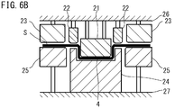
- FIG. 6B shows a step of forming the recess 4 by press working (first intermediate press working step).
- FIG. 6C shows a step of forming the first vertical wall portion 5A and the intermediate flange portion 7A by press working (second intermediate press working step).
- an intermediate press working apparatus 20 shown in FIG. 6A is used.
- the intermediate press working apparatus 20 includes a central punch 21, an intermediate punch 22, and an outer punch 23 as an upper die, and a central die 24 and a blank holder 25 as a lower die.
- the upper mold and the lower mold are paired.
- the punch end surface of the central punch 21 (the end surface to be pressed by hitting the blank material S) has a shape corresponding to the concave portion 4 of the intermediate molded product 1A. Specifically, the shape of the punch end surface of the central punch 21 and the side surfaces in the vicinity of the punch end surface correspond to the shapes of the bottom surface portion and the side surface portion of the recess 4.
- the intermediate punch 22 is disposed outside the central punch 21 and inside the outer punch 23.
- the shape of the punch end surface of the intermediate punch 22 corresponds to the shape of the edge 3 of the top plate 2.
- the intermediate punch 22 has a clearance with the central punch 21.
- the outer punch 23 is disposed outside the intermediate punch 22 and next to the intermediate punch 22.
- the outer punch 23 has a clearance with the intermediate punch 22.
- the end face of the central die 24 (the end face that hits the blank material S) faces the punch end face of the central punch 21 and the punch end face of the intermediate punch 22.
- the shape of the die end surface of the central die 24 corresponds to the shape of the top plate portion 2.
- the die end surface of the central die 24 includes a recess 24 ⁇ / b> A corresponding to the recess 4 and an edge 24 ⁇ / b> B corresponding to the edge 3.
- the blank holder 25 is disposed outside the central die 24 and next to the central die 24.
- the blank holder 25 has a clearance between the central die 24.
- the end surface of the blank holder 25 faces the punch end surface of the outer punch 23.
- the blank holder 25 is used for forming the first vertical wall portion 5A and the intermediate flange portion 7A.
- the center punch 21, the intermediate punch 22, and the outer punch 23 are supported by the upper die holder 26.
- the center punch 21, the intermediate punch 22, and the outer punch 23 are movable (movable up and down) relative to each other.
- a pressure member (not shown) may be disposed between the intermediate punch 22 and the upper mold holder 26, and a pressure member (not illustrated) may be disposed between the outer punch 23 and the upper mold holder 26.
- the pressure member is, for example, a hydraulic cylinder, a gas cylinder, a spring, rubber, or the like.
- the number of pressing members that raise and lower the intermediate punch 22 and the outer punch 23 relative to the central punch 21 may be one, or may be provided independently for each punch as described above.
- a pressure member (not shown) may be provided between the center punch 21 and the upper mold holder 26.
- the moving method of these punches is not particularly limited.
- the central die 24 and the blank holder 25 are supported by the lower mold holder 27.
- the blank holder 25 can be moved up and down relatively with respect to the central die 24.
- a pressure member (not shown) is provided between the blank holder 25 and the lower mold holder 27.
- the pressure member is, for example, as described above.
- the upper holder 26 is attached with a lifting device (slide) (not shown).
- the lifting device is driven to raise and lower the upper mold holder 26 in the vertical direction.
- the lower mold holder 27 is attached to a bolster plate (not shown).
- the intermediate press working apparatus 20 includes the center punch 21, the intermediate punch 22, and the outer punch 23, the center die 24, and the blank holder 25, other configurations are not limited to FIG. 6A.
- the center punch 21, the intermediate punch 22, and the outer punch 23 may be attached to each of a plurality of slides that individually move up and down.
- the flat blank S is disposed between the upper mold and the lower mold of the intermediate press working apparatus 20.
- the punches are arranged so that the punch end surface of the upper central punch 21, the punch end surface of the intermediate punch 22, and the punch end surface of the outer punch 23 are in substantially the same plane. That is, at this time, the punch end surfaces of the punch 21 to punch 23 are arranged at substantially the same height.
- the edge 24B of the central die 24 and the end face of the blank holder 25 are set to be substantially in the same plane.
- the blank material S is disposed on the central die 24 and the blank holder 25 in contact with the edge 24B of the central die 24 and the end surface of the blank holder 25.
- the first intermediate press working process is performed. Specifically, the lifting device (slide) is driven to lower the upper mold holder 26. For example, the punches 21 to 23 are lowered while the heights of the end faces of the punches 21 to 23 remain the same until the punches 21 to 23 come into contact with the upper surface of the blank S.
- the center punch 21, the intermediate punch 22 and the outer punch 23 come into contact with the upper surface of the blank S.
- the blank material S is sandwiched and restrained between the punch end surface of the central punch 21 and the edge 24 ⁇ / b> B of the central die 24.
- the blank material S is further restrained by being sandwiched between the punch end surface of the outer punch 23 and the end surface of the blank holder 25.
- the blank S is sandwiched between the intermediate punch 24 and the edge 24 ⁇ / b> B of the central die 24, and the central punch 21 is relative to the intermediate punch 22 and the outer punch 23 while being sandwiched between the outer punch 23 and the blank holder 25.
- the target is further lowered, and the blank 4 is pressed (drawn) to form the recess 4 (see FIG. 6B).
- the recess 4 of the blank S is sandwiched and restrained by the punch end surface of the center punch 21 and the recess 24A of the center die 24. That is, when the first intermediate press process is completed, the blank S is sandwiched between the punches 21 to 23, the central die 24, and the blank holder 25.
- a second intermediate press process is performed to form the first vertical wall 5A and the intermediate flange part 7A of the intermediate molded product 1A (second intermediate press process).
- the central punch 21 and the intermediate punch 22 and the central die 24 sandwich the blank material S
- the outer punch 23 and the blank holder 25 sandwich the blank material S.
- the outer punch 23 and the blank holder 25 are lowered relative to the punch 22 and the central die 24, and the blank material S is pressed (see FIG. 6C).
- the first vertical wall portion 5A and the intermediate flange portion 7A are formed on the blank S, and the intermediate molded product 1A is formed.
- the concave portion 4 is formed in the first intermediate press working step, and the edge portion 3A, the first vertical wall portion 5A and the intermediate portion arranged outside the concave portion 4 in the subsequent second intermediate press working step.
- the flange portion 7A is formed. If the first vertical wall portion 5A and the intermediate flange portion 7A are formed prior to the formation of the recess 4, the material is pulled in the portion of the blank material S inside the first vertical wall portion 5A. It becomes a state. When the center punch 21 is lowered while the material is pulled, the material to be drawn into the recess 24A of the center die 24 is insufficient. That is, the material necessary for forming the recess 4 is insufficient.
- the thickness of the recess 4 of the intermediate molded product 1 ⁇ / b> A varies, or the recess 4 is cracked.
- the concave portion 4 is formed in the first intermediate press working step, and then the outer edge portion 3, the first vertical wall portion 5A, and the second intermediate press working step.
- the intermediate flange portion 7A is formed.
- the outer punch 23 and the blank holder are held with the blank S having the recess 4 formed between the center punch 21, the intermediate punch 22 and the center die 24.
- the first vertical wall portion 5A and the intermediate flange portion 7A are formed by performing a press work by 25, and the intermediate molded product 1A is manufactured. Therefore, generation
- the distance (gap) between the punch end surface of the intermediate punch 22 and the end surface of the edge 24B of the center die 24. ) And the gap (gap) between the punch end surface of the outer punch 23 and the end surface of the blank holder 25 are about 0.1 mm (more specifically, for example, 0.05 to 0. It is preferred to maintain the gap dimension plus the additional dimension of 3 mm).
- This gap dimension can be realized by the following configuration, for example.
- a spacer (not shown) is provided on the outer edge of the edge 24 ⁇ / b> B of the central die 24 and / or a part of the outer edge of the end face of the blank holder 25.
- the spacer has a thickness of the above-described added dimension, and contacts the punch end surface of the intermediate punch 22 and / or the punch end surface of the outer punch 23.
- the blank S has a gap (gap) between the punch end face of the intermediate punch 22 and the end face of the edge 24B of the central die 24, and a gap (gap) between the punch end face of the outer punch 23 and the end face of the blank holder 25. ) In a loosely pinched state.
- the first intermediate press working step and the second intermediate press working step are performed using one intermediate press working device 20.
- the blank material S may be formed into the intermediate molded product 1A by performing the first intermediate press working step and the second intermediate press working step using separate intermediate press working apparatuses (separate molds).
- separate intermediate press working apparatuses separate molds.
- the intermediate press working step according to the present embodiment also includes a blank material arranging step, a first intermediate press working step, and a second intermediate press working step, as in the first embodiment.
- FIG. 7A is a schematic diagram of the first intermediate press working apparatus 30 used in the first intermediate press working process.
- the first intermediate press working apparatus 30 is a general press working apparatus.
- the first intermediate press working apparatus 30 includes a central punch 31 and a blank holder 33 as an upper die, and a die 32 as a lower die.
- the punch end surface of the center punch 31 has a shape corresponding to the bottom surface portion 4A of the recess 4 of the top plate portion 2 of the intermediate molded product 1A, and the punch side surface adjacent to the punch end surface of the center punch 31 is the top plate portion. 2 has a shape corresponding to the side surface portion 4B of the recess 4.
- the blank holder 33 is disposed outside the central punch 31 and next to the central punch 31.
- the center punch 31 and the blank holder 33 are supported by the upper mold holder 34.
- a pressure member (not shown) is disposed between the blank holder 33 and the upper mold holder 34, and the blank holder 33 is supported by the upper mold holder 34 so as to be movable up and down relative to the central punch 31 by the pressure member.
- the pressure member is the same as the pressure member of the intermediate press working apparatus 20 of the first embodiment.
- the upper mold holder 34 is attached to a lifting device (slide) (not shown).
- the central punch 31 and the blank holder 33 may be attached to slides that move up and down individually.
- the die 32 has an opening in a portion of the end face that faces the end face of the central punch 31. Of the end face of the die 32, the part other than the opening is opposed to the end face of the blank holder 33.
- the die 32 is supported by the lower mold holder 35.
- the blank material S is arranged on the end face of the die 32 of the first intermediate press working apparatus 30 (blank material arranging process). At this time, the blank material S is disposed between the center punch 31 and the blank holder 33 and the die 32.
- the end face of the central punch 31 and the end face of the blank holder 33 are arranged in substantially the same plane. In other words, the end face of the central punch 31 and the end face of the blank holder 33 are arranged at substantially the same height.
- the first intermediate press working process is performed.
- the upper mold holder 34 is lowered by a slide (not shown). If the lowering of the upper mold holder 34 is continued, the end face of the central punch 31 and the end face of the blank holder 33 come into contact with the blank material S (see FIG. 7B). At this time, the blank material S is sandwiched between the blank holder 33 and the die 32.
- the upper mold holder 34 is further lowered relative to the blank holder 33.
- the central punch 31 is further lowered and pushed into the blank material S to form the recess 4 (see FIG. 7C).
- the blank material S is pressed by the above-described known method. Therefore, detailed description of operations of the die 32 and the blank holder 33 is omitted.
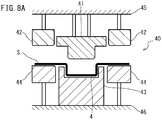
- FIG. 8A to 8C are cross-sectional views schematically showing the second intermediate press working step of the present embodiment.
- FIG. 8A shows a process of placing the blank S in which the recess 4 is formed in the second intermediate press working apparatus 40.
- FIG. 8B shows a step of sandwiching the blank material S in which the recess 4 is formed.
- FIG. 8C shows a process of molding the intermediate molded product 1A.
- a second intermediate press working apparatus 40 used in the second intermediate press working step includes a central punch 41 and an outer punch 42 as an upper die, a central die 43 as a lower die, and a blank.
- the punch end surface shape of the central punch 41 corresponds to the shape of the top plate portion 2 (the concave portion 4 and the edge portion 3) of the intermediate molded product 1A.
- the outer punch 42 is disposed outside the central punch 41 and next to the central punch 41.
- the outer punch 42 has a clearance with the central punch 41.
- the end surface of the outer punch 42 is flat.
- the end surface shape of the central die 43 corresponds to the shape of the top plate portion 2 (the concave portion 4 and the edge portion 3) of the intermediate molded product 1A, and the shape of the side surface portion connected to the end surface of the central die 43 is the first shape of the intermediate molded product 1A. This corresponds to the shape of one vertical wall 5A.
- the end face of the central die 43 faces the punch end face of the central punch 41.
- the blank holder 44 is disposed outside the central die 43 and next to the central die 43.
- the blank holder 44 has a clearance between the central die 43.
- the end surface of the blank holder 44 is flat and faces the end surface of the outer punch 42.
- the center punch 41 and the outer punch 42 are supported by the upper mold holder 45.
- a pressure member (not shown) is provided between the center punch 41 and the upper mold holder 45.
- the pressure member is the same as the pressure member of the first embodiment.
- the center punch 41 is supported by the upper mold holder 45 so as to be movable up and down relative to the outer punch 42.
- the upper mold holder 45 is attached to a lifting device (slide) (not shown).
- the central die 43 and the blank holder 44 are supported by the lower mold holder 46.
- a pressure member (not shown) is provided between the blank holder 44 and the lower mold holder 46.
- the blank holder 44 is supported by the lower mold holder 46 so as to be movable up and down relatively with respect to the central die 43.
- the second intermediate press working apparatus 40 is not limited to FIG. 8A.
- the center punch 41 and the outer side punch 42 may be attached to the slide which raises / lowers each separately.
- the blank material S in which the recess 4 is formed is disposed on the end face of the central die 43 and the blank holder 44 of the second intermediate press working device 40.
- the concave portion 4 formed in the blank material S in the first intermediate press working step is in contact with the portion corresponding to the concave portion 4 in the end face of the central die 43.
- the part corresponding to the edge 3 of the end face of the central die 43 and the end face of the blank holder 44 are arranged in substantially the same plane and are arranged at substantially the same height.
- a portion other than the concave portion 4 is in contact with a portion corresponding to the edge 3 in the end surface of the central die 43 and the end surface of the blank holder 44.
- the portion corresponding to the edge 3 of the end face of the central punch 41 and the end face of the outer punch 42 are arranged in substantially the same plane and are arranged at substantially the same height.
- the upper mold holder 45 is lowered.
- the punch end surface of the central punch 41 and the punch end surface of the outer punch 42 come into contact with the blank material S. That is, in the blank S, a portion corresponding to the recess 4 and the edge 3 is sandwiched between the center punch 41 and the center die 43, and the other portions are sandwiched between the outer punch 42 and the blank holder 44.
- the upper mold holder 45 is further lowered.
- the central punch 41 and the central die 43 sandwich the blank material S including the concave portion 4 and the edge 3, and the outer punch 42 and the blank holder 44 hold the blank material S while the outer punch 42 and the blank holder 44 sandwich the blank material S.
- the blank material S is pressed, the first vertical wall portion 5A and the intermediate flange portion 7A are molded, and the intermediate molded product 1A is manufactured (FIG. 8C).
- press working is performed while the concave portion 4 and the edge portion 3 of the blank S are restrained, and the first vertical wall portion 5A and the intermediate flange portion 7A are formed.
- the recessed part 4 is shape
- the distance (gap) between the end surface of the blank holder 33 and the end surface of the die 32 is the thickness of the blank material S. It is preferable to maintain a dimension obtained by adding an additional dimension of about 0.1 mm (more specifically, for example, 0.05 to 0.3 mm). This gap dimension can be realized by the following configuration, for example.
- a spacer (not shown) is provided on a part of the outer edge of the end face of the die 32. The spacer has a thickness of the above-mentioned added dimension and contacts the blank holder 33.
- the blank material S contacts in the state pinched
- a force for sandwiching the blank material S may be applied to such an extent that no wrinkles are generated without providing the gap.
- the distance (gap) between the end surface of the outer punch 42 and the end surface of the blank holder 44 is the blank material S. It is preferable to maintain the plate thickness by adding an additional size of about 0.1 mm (more specifically, for example, 0.05 to 0.3 mm).
- This gap dimension can be realized by the following configuration, for example.
- a spacer (not shown) is provided on a part of the outer edge of the end face of the blank holder 44. The spacer has a thickness of the above-described added dimension and contacts the outer punch 42. Thereby, the blank material S contacts in the state pinched
- the pressing process may be performed cold or the pressing process may be performed warm.
- the term “cold” here means room temperature (about 25 ° C.).
- the warm refers to a temperature of less than 100 ° C. ⁇ A 1 transformation point of the steel sheet which is a material of the blank S. Further, the blank material S is heated to above the A 1 transformation point, it may be performed pressed at hot.
- the hot referred means or the A 1 transformation point.
- the intermediate molded product 1A manufactured by the intermediate press working process is heated in the heating process. Furthermore, with respect to the heated intermediate molded product 1A, using the final press working apparatus, the heated intermediate molded product 1A is quenched while being pressed (that is, hot stamping is performed) A panel-shaped molded product 1 is manufactured.
- the heating step and the final press working step will be described in detail.
- the intermediate molded product 1A is heated using a heating device.
- the intermediate molded product 1A is charged into a batch-type heating furnace 60 and heated.
- the intermediate molded article 1A the material of the steel sheet of the intermediate molded article 1A is preferably heated at A 1 transformation point or more, more preferably heated above A 3 transformation point.
- a preferable heating temperature is 700 ° C. or higher, and more preferably 900 ° C. or higher.
- the upper limit with preferable heating temperature is 980 degreeC.
- heating may be performed by energization.
- the microstructure after later hot stamping comprises martensite. Therefore, the strength of the panel-shaped molded product is increased.
- the heating temperature can be appropriately designed depending on the steel type of the material, the difficulty of forming, and the like. After heating, the intermediate molded product 1A is extracted from the heating furnace 60, and a hot stamping process is performed.
- Hot stamping means that the heated intermediate molded product 1A is quenched and quenched while being pressed.
- the microstructure of the panel-shaped molded product 1 made of a steel plate includes martensite, and the strength of the panel-shaped molded product 1 is increased.
- FIG. 10A is a schematic diagram of the final press working apparatus 50 used in the final press working process.
- the final press working apparatus 50 includes a central punch 51 and an outer punch 52 as an upper die, and a central die 53 and a blank holder 54 as a lower die.
- the punch end surface shape of the center punch 51 corresponds to the top plate portion 2 (the concave portion 4 and the edge portion 3) of the panel-shaped molded product 1, and the side surface shape in the vicinity of the punch end surface corresponds to the shape of the first vertical wall portion 5A.
- the outer punch 52 is disposed outside the central punch 51 and next to the central punch 51.
- the outer punch 52 has a clearance between the outer punch 52 and the central punch 51.
- the end face 52A of the outer punch 52 is substantially flat and faces the end face 54A of the blank holder 54.
- the central die 53 includes an end surface 53A and a side surface 53C.
- the end surface 53A includes a concave portion 531, an edge portion 532, a vertical wall portion 533, and a step surface portion 534.
- the shape of the recess 531 corresponds to the shape of the recess 4 of the panel-shaped molded product 1.
- the edge 532 is disposed outside the recess 531 and adjacent to the recess 531.
- the edge portion 532 is connected to the recessed portion 531.
- the shape of the edge portion 532 corresponds to the shape of the edge portion 3 of the panel-shaped molded product 1.
- the vertical wall portion 533 extends downward from the outer edge of the edge portion 532.
- the shape of the vertical wall portion 533 corresponds to the first vertical wall portion 5A of the panel-shaped molded product 1.
- the step surface portion 534 is outside the vertical wall portion 533 and is connected to the lower end of the vertical wall portion 533.
- the shape of the stepped surface portion 534 corresponds to the shape of the stepped portion 6 of the panel-shaped molded product 1. Therefore, the height between the step surface portion 534 and the edge portion 532 corresponds to the step height H1 of the panel-shaped molded product 1.
- the side surface 53 ⁇ / b> C extends from the outer edge of the step surface portion 534 to the lower side of the final press working apparatus 50.
- the shape of the side surface 53C corresponds to the shape of the second vertical wall portion 5B of the panel-shaped molded product 1.
- the end face 53A of the central die 53 faces the end face of the central punch 51.
- the blank holder 54 is disposed outside the central die 53 and next to the central die 53.
- the blank holder 54 has a clearance between the central die 53.
- the end face 54A of the blank holder 54 is flat.
- the end surface 54 ⁇ / b> A of the blank holder 54 faces the end surface 52 ⁇ / b> A of the outer punch 52.
- the central punch 51 and the outer punch 52 are supported by the upper mold holder 55.
- the center punch 51 is attached to the upper mold holder 55 so as to be movable up and down relative to the outer punch 52.
- the center punch 51 is supported by the upper mold holder 55 via a pressure member (not shown).
- the center punch 51 and the outer punch 52 may be attached to the upper mold holder 55 so as to be individually movable up and down.
- the upper mold holder 55 is attached to a lifting device (slide) (not shown) and can be lifted and lowered.
- the central die 53 and the blank holder 54 are supported by the lower mold holder 56.
- the blank holder 54 is supported by the lower mold holder 56 so as to be movable up and down relatively with respect to the central die 53.
- the blank holder 54 is supported by the lower mold holder 56 via a pressure member (not shown).
- the central die 53 and the blank holder 54 may be attached to the lower mold holder 56 so as to be individually movable up and down.
- the initial height of the end surface 54A of the blank holder 54 is lower than the height of the step surface portion 534 of the central die 53.
- the initial height difference h0 shown in FIG. 10A is provided between the height of the end face 54A and the height of the stepped surface portion 534 in the initial stage (before pressing).
- the initial height difference h0 is, for example, 1.0 to 5.0 mm.
- the final pressing process using the above-described final pressing apparatus 50 includes the following pre-process and post-process.
- Pre-process The intermediate molded product 1A is arranged on the central die 53, the intermediate molded product 1A is sandwiched between the central punch 51 and the central die 53, and the intermediate molded product 1A is sandwiched between the outer punch 52 and the blank holder 54.
- Post-process panel-shaped molding by moving the outer punch 52 and the blank holder 54 with the intermediate molded product 1A sandwiched relative to the central punch 51 and the central die 53 with the intermediate molded product 1A sandwiched therebetween Article 1 is manufactured.
- the preceding step further includes the following first step and second step.
- First step The intermediate molded product 1A is arranged, the intermediate molded product 1A is sandwiched between the central punch 51 and the central die 53, and the outer punch 52 is brought into contact with the intermediate molded product 1A.
- the press working of the intermediate molded product 1A before performing the press working in the subsequent process can suppress that the temperature of the part which applies is reduced. Thereby, sufficient hardenability can be ensured while maintaining the workability of the intermediate molded product 1A at the time of press working in a subsequent process.
- the pre-process and the post-process will be described.
- the pre-step includes the first step and the second step.
- First step In the first step, first, as shown in FIG. 10B, the intermediate molded product 1A heated in the heating step is placed on the central die 53 and the blank holder 54 of the final press working apparatus 50.
- the concave portion 531 of the end surface 53A of the central die 53 is in contact with the concave portion 4 of the intermediate molded product 1A, and the edge 532 of the end surface 53A of the central die 53 is the intermediate molded product 1A.
- the vertical wall portion 533 of the end surface 53A of the central die 53 is in contact with the first vertical wall portion 5A of the intermediate molded product 1A.
- the stepped surface portion 534 of the end surface 53A of the central die 53 is in contact with the intermediate flange portion 7A of the intermediate molded product 1A.
- the end surface 54A of the blank holder 54 is disposed lower than the step surface portion 534 by the initial height difference h0. Therefore, when the intermediate molded product 1 ⁇ / b> A is disposed on the central die 53, the intermediate molded product 1 ⁇ / b> A is disposed on the central die 53 without contacting the blank holder 54.
- the central punch 51 and the outer punch 52 are lowered. At this time, among the punch end faces of the central punch 51, the end face portion corresponding to the stepped portion 6 of the panel-shaped molded product 1 and the end face 52A of the outer punch 52 are lowered while maintaining substantially the same height.
- the central punch 51 and the outer punch 52 are lowered, and the intermediate molded product 1A is sandwiched between the central punch 51 and the central die 53 as shown in FIG. 10C.
- the end face 52A of the outer punch 52 contacts the intermediate molded product 1A (the intermediate flange portion 7A) almost simultaneously with the contact of the central punch 51 with the intermediate molded product 1A.
- the end face 54A of the blank holder 54 is not in contact with the intermediate molded product 1A.
- the intermediate molded product 1A is sandwiched between the central punch 51 and the central die 53, and the outer punch 52 is brought into contact with the intermediate molded product without bringing the blank holder 54 into contact with the intermediate molded product 1A.
- the intermediate flange portion 7A does not come into contact with the end face 54A of the blank holder 54, the temperature of the intermediate flange portion 7A is unlikely to decrease before the press working. Therefore, the temperature drop of the intermediate molded product 1A before press working can be suppressed, and good workability can be maintained.
- the initial height difference h0 is preferably 1.0 to 5.0 mm. If the initial height difference h0 is 1.0 mm or more, when the outer punch 52 is brought into contact with the intermediate molded product 1A, a sufficient gap can be secured between the blank holder 54 and the intermediate molded product 1A. In this case, the intermediate molded product 1A does not contact the end surface 54A of the blank holder 54 before the end surface 52A of the outer punch 52 contacts the intermediate molded product 1A. Therefore, before the outer punch 52 and the blank holder 54 press the intermediate molded product 1A, the temperature of the intermediate molded product 1A can be sufficiently suppressed from decreasing. As a result, the processability of the intermediate molded product 1A can be suppressed and sufficient quenching can be performed.
- the gap between the blank holder 54 and the intermediate molded product 1A does not become too large, and an appropriate gap interval is obtained. Therefore, the time from when the outer punch 52 comes into contact with the intermediate molded product 1A until the intermediate molded product 1A comes into contact with the blank holder 54 can be shortened, and wrinkles and the like due to press working are further less likely to occur.
- the initial height difference h0 is not limited to 1.0 to 5.0 mm. As shown in FIG. 10C, when the end surface 52A of the outer punch 52 is brought into contact with the intermediate molded product 1A, the initial height difference h0 is not particularly limited as long as the end surface 54A of the blank holder 54 does not contact the intermediate molded product 1A. .
- the outer punch 52 is brought into contact with the intermediate molded product 1 ⁇ / b> A
- the outer punch 52 is lowered relative to the central punch 51 while the intermediate molded product 1 ⁇ / b> A is sandwiched between the central punch 51 and the central die 53.
- the intermediate flange portion 7A of the intermediate molded product 1A is slightly deformed.
- the intermediate flange portion 7A contacts not only the end surface 52A of the outer punch 52 but also the end surface 54A of the blank holder 54. Accordingly, the intermediate molded product 1A (the intermediate flange portion 7A) is sandwiched between the outer punch 52 and the blank holder 54.
- the blank holder 54 does not contact the intermediate molded product 1A until the outer punch 52 contacts the intermediate molded product 1A.
- the outer punch 52 comes into contact with the intermediate molded product 1A (for example, after the outer punch 52 comes into contact with the intermediate flange portion 7A of the intermediate molded product 1A, the outer punch 52 is further lowered by 1.0 to 5.0 mm.
- the blank holder 54 comes into contact with the intermediate flange portion 7A of the intermediate molded product 1A.
- the intermediate molded product 1A is sandwiched between the outer punch 52 and the blank holder 54 while the intermediate molded product 1A is sandwiched between the central punch 51 and the central die 53.
- the panel-shaped molded product 1 is manufactured by the above process.
- a cooling medium such as water circulates inside the center punch 51, the outer punch 52, the center die 53, and the blank holder 54. Therefore, the intermediate molded product 1A being pressed is rapidly cooled. That is, in the final pressing process, the intermediate molded product 1A is rapidly cooled (quenched) while being pressed.
- the intermediate molded product 1A is quenched while being pressed. Therefore, the microstructure of the panel-shaped molded product 1 contains martensite. Therefore, a high-strength panel-shaped molded product 1 can be manufactured.
- the outer punch 52 is first brought into contact with the intermediate molded product 1A (first step), and then the blank holder 54 is brought into contact with the intermediate molded product 1A (second step). If the intermediate molded product 1A is disposed on the central die 53 and the end surface 54A of the blank holder 54 is the same height as the step surface portion 534 of the central die 53, the blank holder 54 comes into contact. In this case, the temperature of the intermediate flange portion 7A is lowered before the outer punch 52 comes into contact with the intermediate flange portion 7A. Therefore, press working becomes difficult. In addition, it becomes difficult to perform sufficient quenching.
- the distance (gap) between the end surface 52A of the outer punch 52 and the end surface 54A of the blank holder 54 is the intermediate molded product. It is preferable to maintain a dimension obtained by adding about 0.1 mm to the thickness of 1A (for example, a dimension obtained by adding 0.05 to 0.3 mm to the thickness of the intermediate molded product 1A).
- the blank holder 54 has a spacer (not shown) on a part of the outer edge of the end face 54A.
- the spacer has a thickness of a dimension obtained by adding about 0.1 mm to the thickness of the intermediate molded product 1A (for example, a dimension obtained by adding 0.05 to 0.3 mm to the thickness of the intermediate molded product 1A). Therefore, when the outer punch 52 and the blank holder 54 sandwich the intermediate molded product 1 ⁇ / b> A, the outer punch 52 comes into contact with the spacer of the blank holder 54. Therefore, the gap between the outer punch 52 and the blank holder 54 has the above dimensions. In this case, the intermediate molded product 1 ⁇ / b> A is loosely sandwiched between the outer punch 52 and the blank holder 54. Therefore, the intermediate molded product 1A is not excessively constrained at the time of pressing, and the material is easily pulled in according to deformation. Therefore, the press work is smoothly performed.
- the stepped portion 6 of the intermediate molded product 1A and the intermediate flange portion 7A are formed on the stepped portion 6A.
- the region to be held is sandwiched and restrained by the central punch 51 and the central die 53. Thereby, defects, such as wrinkles, do not easily occur in the panel-shaped molded product 1.
- this point will be described in detail.
- FIG. 11 is a cross-sectional view showing a state during press working by a conventional final press working apparatus.
- the vicinity of the step surface of the punch of the conventional final press working apparatus is shown enlarged.
- the step surface portion 220B and the reference end surface 220C of the punch 220 are integrally formed. Therefore, during the press working, the reference end surface 220C of the punch 220 reaches the end surface 230C of the blank holder 230 earlier than the end surface portion 220A and the step surface portion 220B of the punch 220 reach the end surface portion 210A and the step surface portion 210B of the die 210. To do. At this time, the region S1 of the blank material S pushed into the stepped surface portion 220B of the punch 220 is not restrained. That is, the region S1 of the blank S does not contact the die 210 and the punch 220.
- the blank material S is drawn to the end surface portion 220 ⁇ / b> A side of the punch 220. Therefore, the material of the blank material S tends to flow into the region S1 from the region sandwiched between the blank holder 230 and the punch 220. If the region S1 is pressed with the material flowing into the region S1, wrinkles are likely to occur in the region S1. This is because there is an extra material flowing into the region S1. Further, during pressing, the unconstrained region S1 receives tension. If the region S1 is pressed in a state where the region S1 is under tension, a crack is likely to occur in the region S1. In particular, when the thickness of the blank material S is thin, cracks are likely to occur.
- the press working process is separated into two processes, an intermediate press working process and a final press working process.
- the intermediate press working step the intermediate molded product 1A molded up to the height of the stepped portion 6 of the panel-shaped molded product 1 is molded in advance.
- the final press working step the outer side of the intermediate molded product 1A is restrained with the central punch 51 and the central die 53 sandwiching the regions corresponding to the concave portion 4, the edge portion 3, the first vertical wall portion 5A and the step portion 6 of the intermediate molded product 1A.
- the punch 52 and the blank holder 54 press the intermediate flange portion 7A of the intermediate molded product 1A.
- there are very few free regions regions such as region S1 in FIG. 11
- the generation of wrinkles and cracks is suppressed.
- the preceding process may be performed without being divided into the first process and the second process. That is, the blank holder 54 may contact the intermediate molded product 1A before the outer punch 52 contacts the intermediate molded product 1A. Even in this case, generation of wrinkles and the like can be suppressed by performing two-stage pressing in the intermediate pressing process and the final pressing process.
- the pre-step of the final press working step is performed in the first step and the second step. This is because the temperature drop of the press-formed portion of the intermediate molded product 1A before hot stamping can be suppressed, so that the workability of the intermediate molded product 1A during hot stamping can be maintained and the hardenability can be sufficiently secured.
- the above-described cracking and wrinkle suppression of the panel-shaped molded product 1 is the same when the blank S is molded into the intermediate molded product 1A in the intermediate press working step.
- the intermediate press working step when the edge 3 and the first vertical wall 5A are formed on the blank S in the second intermediate press working step, the concave portion 4 and the edge 3 already formed in the first intermediate press working step are formed.
- the region to be processed is constrained (see FIGS. 6B and 6C, FIG. 8B and FIG. 8C). That is, in the second intermediate press working step, there are few free regions such as the S1 region in the blank S in FIG. Therefore, wrinkles and the like are hardly generated in the molded intermediate molded product 1A.
- the intermediate molded product 1A may be molded cold. Even in the cold working, if there is a free region such as the S1 region in FIG.
- the edge 3 and the first vertical wall are restrained while constraining the region where the concave portion 4 and the edge 3 are formed. Part 5A is formed. Therefore, it is difficult for wrinkles or the like to occur in the intermediate molded product 1A regardless of whether the intermediate press working process is a cold process, a warm process, or a hot process.
- the blank material S is cooled by contact with the punch, die, and blank holder.
- the portion S1 of the blank S is not cooled for the reason described above.
- a part S1 of the blank S is cooled when the punch 220 is further lowered from the position shown in FIG.
- the part S1 of the blank S is cooled later than the other part as described above.
- the center punch 51 and the center die 53 sandwich the regions corresponding to the recess 4, the edge 3, the first vertical wall 5A, and the step 6 of the intermediate molded product 1A.
- the outer punch 52 and the blank holder 54 are pressed while sandwiching the intermediate flange 7A of the intermediate molded product 1A.
- the intermediate molded product 1A there are few free regions that are not constrained in the region to be pressed. Therefore, even if hot stamping is performed in the final press working process, generation of wrinkles and the like is suppressed.
- the manufacturing method of the present embodiment can also be applied to the manufacture of the panel-shaped molded product 1 using a metal plate other than the steel plate as a raw material.
- the metal plate include aluminum, an aluminum alloy, a multilayer steel plate, titanium, and magnesium.
- the heating process is performed, and the hot stamping is performed in the final press working process.
- the panel-shaped molded product 1 may be manufactured by omitting the heating process for the intermediate molded product 1A and performing a cold press in the final pressing process.
- the tensile strength of the panel-shaped molded product 1 manufactured by performing cold pressing in the final pressing process is preferably 340 MPa or more.
- the final press working apparatus when cold pressing is performed in the final press working process has the same configuration as the final press working apparatus 50 shown in FIG. 10A.
- the cooling medium may not be circulated in the center punch 51, the outer punch 52, the center die 53, and the blank holder 54.
- the end surface 54 ⁇ / b> A of the blank holder 54 may be disposed at the same height as the step surface portion 534 of the central die 53.
- the manufacturing method for manufacturing the panel-shaped molded article 1 by cold pressing using the final press processing apparatus having the same configuration as that in FIG. 10A includes a preparation step, an intermediate press processing step, and a final press processing step. That is, when the cold pressing is performed, the heating step is omitted as compared with the case where the hot stamping is performed.
- the final press working process includes the following pre-process and post-process.
- Pre-process An intermediate molded product 1A (at room temperature) is placed on the central die 53, the intermediate molded product 1A is sandwiched by the central punch 51 and the central die 53, and further, the intermediate molded product 1A is formed by the outer punch 52 and the blank holder 54. Between.
- Post-process panel-shaped molding by moving the outer punch 52 and the blank holder 54 with the intermediate molded product 1A sandwiched relative to the central punch 51 and the central die 53 with the intermediate molded product 1A sandwiched therebetween Article 1 is manufactured.
- the intermediate molded product 1A is arranged on the central die 53 and the blank holder 54 in the previous process in the final press working process. After the placement, the central punch 51 and the outer punch 52 are lowered. At this time, the central punch 51 and the outer punch 52 are kept substantially the same in height between the end surface portion corresponding to the stepped portion 6 of the panel-shaped molded product 1 and the end surface 52A of the outer punch 52 among the end surfaces of the central punch 51. Descent. As a result, the intermediate molded product 1A is sandwiched between the central punch 51 and the central die 53, and the intermediate flange portion 7A of the intermediate molded product 1A is sandwiched between the outer punch 52 and the blank holder 54.
- the first step and the second step are steps for suppressing the temperature of the processed portion (outer edge portion) of the intermediate molded product 1A from being lowered before the hot stamping is performed. Therefore, in the case of cold pressing in which the intermediate molded product 1A is pressed without heating, the intermediate molded product 1A is not at a high temperature, and thus the previous process does not have to be divided into the first and second processes.
- the intermediate press working process and the final press working process are performed in the final press working process.
- stamping it is possible to suppress the occurrence of wrinkles and cracks in the panel-shaped molded product.
- the depressed portion 11 and / or the raised portion can be manufactured in an intermediate press working step.
- the intermediate press working step the intermediate depressed portion and / or the intermediate raised portion corresponding to the depressed portion 11 and / or the raised portion are formed in the concave portion 4, and then the depressed portion 11 and the raised portion are formed in the final press working step.
- the part may be molded.
- the arrangement of the punch, the die, and the blank holder is not limited to the case shown in each drawing.
- the arrangement of the upper die and the lower die constituted by punches, dies, blank holders and the like may be turned upside down.
- the panel-shaped molded product 1 (door inner) shown in FIG. 1 is manufactured by the manufacturing method of the first embodiment using the intermediate press working apparatus 20 shown in FIG. 6 and the final press working apparatus 50 shown in FIG. 10A. Panel).
- the comparative example it was assumed that a panel-like molded product (door inner panel) similar to the example of the present invention was manufactured by using the conventional hot stamping device shown in FIG. The following analysis method was implemented with respect to the examples of the present invention and comparative examples, and the state of occurrence of wrinkles in the panel-shaped molded product was evaluated from the analysis results.
- the dimensions of the panel-shaped molded product as the door inner panel were as follows. ⁇ Full length (including flange): 950 mm ⁇ Full width (including flange): 670mm ⁇ Total length of top plate: 830mm ⁇ Full width of top plate: 600mm -Height of the first vertical wall: 40 mm -Height of the second vertical wall: 40 mm ⁇ Minimum width of the step: 40mm
- the initial height of the end surface 54A of the blank holder 54 is set to a height that is 3.0 mm lower than the step surface portion 534 of the central die 53. Accordingly, in the example of the present invention, after the center punch 51 and the outer punch 52 contacted the intermediate molded product 1A, the outer punch 52 further dropped by 3.0 mm, and then the blank holder 54 contacted the intermediate molded product 1A.
- the curvature radius of the unevenness existing on the surface of the stepped portion 6 was calculated, and the minimum value thereof was adopted as the curvature radius in the above formula.
- the curvature was 0.01 or more, it was determined that wrinkles were generated in the panel-shaped molded product.
Abstract
Description
10<W<0.2×L (1)
最終プレス加工工程では、最終プレス加工装置を用いて、中間成形品にプレス加工を施してパネル状成形品を製造する。
最終プレス加工装置は、中央ダイと、ブランクホルダと、中央パンチと、外側パンチとを備える。
中央ダイは、パネル状成形品のうち天板部から段差部の外縁までの形状に対応する端面形状を含む。
ブランクホルダは、中央ダイの外側であって中央ダイの隣に配置される。
中央パンチは、中央ダイに対向し、パネル状成形品のうち天板部から段差部の外縁までの形状に対応する端面形状を含む。
外側パンチは、中央パンチの外側であって中央パンチの隣に配置され、ブランクホルダに対向する。
最終プレス加工工程は、前工程と、後工程とを含む。
前工程では、中央ダイ上に中間成形品を配置して、中央パンチ及び中央ダイにより中間成形品を挟み、さらに、外側パンチ及びブランクホルダにより中間成形品を挟む。
後工程では、中間成形品を挟んだままの中央パンチ及び中央ダイに対して、中間成形品を挟んだままの外側パンチ及びブランクホルダを相対的に移動して、第2縦壁部及びフランジ部を成形してパネル状成形品を成形する。
この場合、最終プレス加工工程の前工程は、第1工程及び第2工程を含む。
第1工程では、中央ダイ上に加熱された中間成形品を配置して、中央パンチ及び中央ダイにより中間成形品を挟み、さらに、外側パンチを中間成形品に接触させる。
第2工程では、外側パンチを中間成形品に接触させた後、中央パンチ及び中央ダイにより中間成形品を挟んだまま、さらに、ブランクホルダを中間成形品に接触させて外側パンチ及びブランクホルダにより中間成形品を挟む。
・全長(フランジ部7を含む):800~1300mm
・全幅(フランジ部7を含む):600~800mm
・天板部2の全長 :700~1200mm
・天板部2の全幅 :500~700mm
・第1縦壁部5Aの高さ :30~100mm
・第2縦壁部5Bの高さ :30~100mm
・段差部の最小幅 :20~40mm
・素材鋼板の板厚 :0.3~2.3mm(好ましくは0.5~1.8mm)
10<W<0.2×L (1)
0.25×H0<H1<H (2)
本実施形態の製造方法は、準備工程と、中間プレス加工工程と、加熱工程と、最終プレス加工工程とを含む。本例では、最終プレス加工工程において、ホットスタンピングを実施する。以下、各工程について説明する。なお、最終プレス加工工程を冷間プレスで実施する場合、加熱工程は省略される。最終プレス加工工程を冷間プレスで実施する場合については後述する。
準備工程では、鋼板からなる平板状のブランク材を準備する。ブランク材としての鋼板の化学組成は、後述のホットスタンピング工程により、ミクロ組織がマルテンサイトを含有すれば、特に限定されない。好ましくは、鋼板の化学組成は、質量%で、炭素(C):0.11%以上含有するのが好ましい。鋼板が0.11%以上のCを含有すれば、ホットスタンピング工程後のパネル状成形品の強度が高い。さらに好ましくは、鋼板の化学組成は、上述のパネル状成形品1の説明で記載したとおりである。
プレス加工工程では、冷間、温間又は熱間で、ブランク材にプレス加工を施し、図5に示す中間成形品1Aを製造する。
図6A~図6Cは、第1実施形態での中間プレス加工工程を模式的に示す断面図である。図6Aは、ブランク材Sを中間プレス加工装置20に配置する工程(ブランク材配置工程)を示す。図6Bは、プレス加工により凹部4を成形する工程(第1中間プレス加工工程)を示す。図6Cは、プレス加工により第1縦壁部5A及び中間フランジ部7Aを成形する工程(第2中間プレス加工工程)を示す。
第1実施形態では、1台の中間プレス加工装置20を用いて第1中間プレス加工工程及び第2中間プレス加工工程を実施した。しかしながら、第1中間プレス加工工程及び第2中間プレス加工工程を別個の中間プレス加工装置(別個の金型)を用いて実施して、ブランク材Sを中間成形品1Aに成形してもよい。以下、2台の中間プレス加工装置を用いたプレス加工工程の第2実施形態を説明する。
中間プレス加工工程により製造された中間成形品1Aを、加熱工程で加熱する。さらに、加熱された中間成形品1Aに対して、最終プレス加工装置を用いて、加熱された中間成形品1Aにプレス加工を施しつつ焼入れを実施して(つまり、ホットスタンピングを実施して)、パネル状成形品1を製造する。以下、加熱工程及び最終プレス加工工程について詳述する。
加熱工程では、加熱装置を用いて中間成形品1Aを加熱する。例えば、図9に示すとおり、中間成形品1Aをバッチ式の加熱炉60に装入して加熱する。加熱工程では、中間成形品1Aを、中間成形品1Aの素材の鋼板をA1変態点以上で加熱するのが好ましく、さらに好ましくはA3変態点以上に加熱する。好ましい加熱温度は700℃以上であり、さらに好ましくは900℃以上である。加熱温度の好ましい上限は980℃である。バッチ式の加熱炉を用いる方法以外では,通電によって加熱してもよい.
本例では、最終プレス加工工程において、最終プレス加工装置を用いて、加熱された中間成形品1Aに対してホットスタンピングを施す。これにより、ドアインナーパネルに代表されるパネル状成形品1が製造される。
図10Aは、最終プレス加工工程で用いる最終プレス加工装置50の模式図である。図10Aを参照して、最終プレス加工装置50は、上型として中央パンチ51と、外側パンチ52とを備え、下型として中央ダイ53と、ブランクホルダ54とを備える。
前工程:中央ダイ53上に中間成形品1Aを配置して、中央パンチ51及び中央ダイ53により中間成形品1Aを挟み、さらに、外側パンチ52及びブランクホルダ54により中間成形品1Aを挟む。
後工程:中間成形品1Aを挟んだままの中央パンチ51及び中央ダイ53に対して、中間成形品1Aを挟んだままの外側パンチ52及びブランクホルダ54を相対的に移動して、パネル状成形品1を製造する。
第1工程:中間成形品1Aを配置して、中央パンチ51及び中央ダイ53により中間成形品1Aを挟み、かつ、外側パンチ52を中間成形品1Aに接触させる。
第2工程:外側パンチ52を中間成形品1Aに接触させた後、中央パンチ51及び中央ダイ53により中間成形品1Aを挟んだまま、さらに、ブランクホルダ54を中間成形品と接触させて、外側パンチ52及びブランクホルダ54とにより中間成形品1Aを挟む。
本例のように最終プレス加工工程においてホットスタンピングを実施する場合、前工程は、上記第1工程及び第2工程を含む。
[第1工程]
第1工程では、初めに、図10Bに示すとおり、加熱工程にて加熱された中間成形品1Aを最終プレス加工装置50の中央ダイ53及びブランクホルダ54上に配置する。
中央パンチ51及び中央ダイ53が中間成形品1Aを挟み、外側パンチ52を中間成形品1Aに接触させた後、第2工程では、中央パンチ51及び中央ダイ53により中間成形品1Aを挟んだまま、さらに、ブランクホルダ54を中間成形品1Aと接触させて外側パンチ52及びブランクホルダ54により中間成形品1Aを挟む(図10D参照)。
前工程(の第2工程)において外側パンチ52及びブランクホルダ54により中間成形品1Aの中間フランジ部7Aを挟んだ後、中間成形品1Aを挟んだままの中央パンチ51及び中央ダイ53に対して、中間成形品1Aを挟んだままの外側パンチ52及びブランクホルダ54を相対的に移動して、図10Eに示すとおり、第2縦壁部5B及びフランジ部7を成形して、パネル状成形品1を成形する。本例では、中間成形品1Aを挟んだままの外側パンチ52及びブランクホルダ54をさらに降下して、プレス加工(ホットスタンピング)を実施する。そして、外側パンチ52が中間フランジ部7Aと接触してからパネル状成形品1の第2縦壁部5Bの高さに相当する距離まで外側パンチ52を降下したとき、外側パンチ52の降下を停止する。以上の工程により、パネル状成形品1が製造される。
図11は、従来の最終プレス加工装置によるプレス加工中の状態を示す断面図である。図11では、従来の最終プレス加工装置のパンチの段差面付近を拡大して示す。従来の最終プレス加工装置200では、パンチ220の段差面部220B及び基準端面220Cは一体的に形成されている。そのため、プレス加工中において、パンチ220の端面部220A及び段差面部220Bがダイ210の端面部210A及び段差面部210Bに到達するよりも早く、パンチ220の基準端面220Cがブランクホルダ230の端面230Cに到達する。このとき、パンチ220の段差面部220Bに押し込まれるブランク材Sの領域S1は、拘束されていない。つまり、ブランク材Sの領域S1は、ダイ210及びパンチ220と接触しない。
上述の実施の形態では、加熱工程を実施して、最終プレス加工工程においてホットスタンピングを実施した。しかしながら、上記製造工程において、中間成形品1Aに対して加熱工程を省略し、最終プレス加工工程において冷間プレスを実施することにより、パネル状成形品1を製造してもよい。ブランク材が鋼板である場合、最終プレス加工工程において冷間プレスを実施して製造されるパネル状成形品1の引張強度は340MPa以上が好ましい。以下、最終プレス加工工程において、冷間プレスを実施する場合について、以下、説明する。
前工程:中央ダイ53上に(常温の)中間成形品1Aを配置して、中央パンチ51及び中央ダイ53により中間成形品1Aを挟み、さらに、外側パンチ52及びブランクホルダ54により中間成形品1Aを挟む。
後工程:中間成形品1Aを挟んだままの中央パンチ51及び中央ダイ53に対して、中間成形品1Aを挟んだままの外側パンチ52及びブランクホルダ54を相対的に移動して、パネル状成形品1を製造する。
冷間プレスにより中間成形品1Aからパネル状成形品1を製造する場合、最終プレス加工工程内の前工程において、中央ダイ53及びブランクホルダ54上に、中間成形品1Aを配置する。配置後、中央パンチ51及び外側パンチ52を降下する。このとき、中央パンチ51の端面のうちパネル状成形品1の段差部6に相当する端面部分と、外側パンチ52の端面52Aとの高さを略同じにしたまま、中央パンチ51及び外側パンチ52を降下する。その結果、中央パンチ51及び中央ダイ53により中間成形品1Aを挟み、かつ、外側パンチ52及びブランクホルダ54により中間成形品1Aのうちの中間フランジ部7Aを挟む。
前工程を実施した後、中央パンチ51及び中央ダイ53により中間成形品1Aを挟んだまま、かつ、外側パンチ52及びブランクホルダ54により中間成形品1Aの中間フランジ部7Aを挟んだまま、外側パンチ52及びブランクホルダ54をさらに降下する。これにより、中間フランジ部7Aがプレス加工され、第2縦壁部5B及びフランジ部7が成形されて、パネル状成形品1が製造される。
解析に用いた素材(発明例では中間成形品1A、比較例ではブランク材)は、質量%で、C:0.21%、Si:0.25%、Mn:1.20%、B:0.0020%を含有し、残部がFe及び不純物からなる鋼板とした。ブランク材の板厚は1.2mmとした。焼入れ後の材料特性は、ビッカース硬さHV:448、降伏強さ:448MPa、引張強さ:1501MPa、及び、破断伸び:6.4%とした。素材の加熱温度は750℃とした。ホットスタンピングでの金型の移動速度は40m/s相当とした。ホットスタンピングにおける金型と素材との摩擦係数は0.4とした。解析には、汎用のFEM解析ソフト(LIVERMORE SOFTWARE TECHNOLOGY社製、商品名LS-DYNA)による熱-成形連成解析を用いた。
・全長(フランジ部含む):950mm
・全幅(フランジ部含む):670mm
・天板部の全長:830mm
・天板部の全幅:600mm
・第1縦壁部の高さ:40mm
・第2縦壁部の高さ:40mm
・段差部の最小幅:40mm
本発明例及び比較例のパネル状成形品について、段差部6の表面に生じた凹凸の曲率を調査した。曲率は、下記の式を用いて算出した。
(曲率[1/m])=(1/(曲率半径))
発明例では、曲率が0.01以上となる断面はなかった。したがって、シワは発生しなかったといえた。一方、比較例では、曲率が0.01以上となる断面が多かった。したがって、シワが発生したといえた。
1A 中間成形品
2 天板部
3 縁部
4 凹部
5 縦壁部
6 段差部
7 フランジ部
8 ウインドウ部材
50 最終プレス加工装置
Claims (13)
- 金属板からなるパネル状成形品であって、
多角形状の天板部と、
前記天板部の外縁の辺のうちの少なくとも2以上の各辺から延びる複数の縦壁部と、
前記縦壁部の下端とつながり、前記天板部の延在方向に延びるフランジ部とを備え、
前記天板部は、
前記天板部の外縁のうち前記縦壁部とつながる辺を含む縁部と、
前記縁部の内側に配置され、前記縁部から凹んだ凹部とを含み、
複数の前記縦壁部のうち、互いに隣り合う少なくとも一組の前記縦壁部の各々は、
第1縦壁部と、
前記第1縦壁部の下端とつながり、前記天板部の延在方向に延びる段差部と、
前記段差部の外縁とつながり、前記第1縦壁部の延在方向に延びる第2縦壁部とを含み、
前記フランジ部は、前記第2縦壁部の下端とつながる、パネル状成形品。 - 請求項1に記載のパネル状成形品であって、
前記縁部の幅W(mm)は、前記天板部の最大幅L(mm)との関係で、式(1)を満たす、パネル状成形品。
10<W<0.2×L (1) - 請求項1又は請求項2に記載のパネル状成形品であって、
前記縁部から前記凹部の底面までの高さは、前記縁部から前記段差部までの高さよりも大きい、パネル状成形品。 - 請求項1~請求項3のいずれか1項に記載のパネル状成形品であって、
前記金属板は鋼板であり、前記鋼板の引張強度は340MPa以上である、パネル状成形品。 - 請求項4に記載のパネル状成形品であって、
前記金属板は鋼板であり、前記鋼板の引張強度は600MPa以上である、パネル状成形品。 - 請求項1~請求項5のいずれか1項に記載のパネル状成形品であって、
前記天板部の前記凹部はさらに、
前記凹部の底面に、前記底面から凹んだ線状の陥没部、及び、前記底面から突出する線状の隆起部のうちの少なくとも一方を含む、パネル状成形品。 - 請求項1~請求項6のいずれか1項に記載のパネル状成形品であって、
前記金属板は、テーラードブランクである、パネル状成形品。 - 請求項1~請求項7のいずれか1項に記載のパネル状成形品であって、
前記パネル状成形品は車両用のドアインナーパネルであり、
前記天板部の外縁の複数の辺のうち、車両上側に対応する前記辺に前記縁部及び前記縦壁部を有さない、パネル状成形品。 - 車両に搭載可能な車両用ドアであって、
請求項7に記載のパネル状成形品と、
前記パネル状成形品の車両外側に配置され、前記ドアインナーパネルと接合されるドアアウターパネルと、
前記凹部に収容可能であり、前記パネル状成形品の車両内側に配置されるウインドウ部材と、を備える、車両用ドア。 - 請求項1に記載のパネル状成形品の製造方法であって、
前記鋼板からなるブランク材を準備する準備工程と、
前記ブランク材にプレス加工を施すことにより、前記天板部を成形するとともに、前記第1縦壁部及び前記段差部の高さまで成形して、中間成形品を製造する中間プレス加工工程と、
最終プレス加工装置を用いて、前記中間成形品にプレス加工を施して前記パネル状成形品を製造する最終プレス加工工程とを備え、
前記最終プレス加工装置は、
前記パネル状成形品のうち前記天板部から前記段差部の外縁までの形状に対応する端面形状を含む中央ダイと、
前記中央ダイの外側であって前記中央ダイの隣に配置されるブランクホルダと、
前記中央ダイに対向し、前記パネル状成形品のうち前記天板部から前記段差部までの形状に対応する端面形状を含む中央パンチと、
前記中央パンチの外側であって前記中央パンチの隣に配置され、前記ブランクホルダに対向する外側パンチとを備え、
前記最終プレス加工工程では、
前記中央ダイ上に前記中間成形品を配置して、前記中央パンチ及び前記中央ダイにより前記中間成形品を挟み、さらに、前記外側パンチ及び前記ブランクホルダにより前記中間成形品を挟む前工程と、
前記中間成形品を挟んだままの前記中央パンチ及び前記中央ダイに対して、前記中間成形品を挟んだままの前記外側パンチ及び前記ブランクホルダを相対的に移動して、前記第2縦壁部及び前記フランジ部を成形して前記パネル状成形品を成形する後工程とを含む、パネル状成形品の製造方法。 - 請求項10に記載のパネル状成形品の製造方法であってさらに、
前記最終プレス加工工程前に、前記中間成形品を加熱する加熱工程を備え、
前記最終プレス加工工程は、加熱された前記中間成形品にプレス加工を施しつつ焼入れを実施して、前記パネル状成形品を製造し、
前記最終プレス加工工程の前記前工程は、
前記中央ダイ上に加熱された前記中間成形品を配置して、前記中央パンチ及び前記中央ダイにより前記中間成形品を挟み、さらに、前記外側パンチを前記中間成形品に接触させる第1工程と、
前記外側パンチを前記中間成形品に接触させた後、前記中央パンチ及び前記中央ダイにより前記中間成形品を挟んだまま、さらに、前記ブランクホルダを前記中間成形品に接触させて前記外側パンチ及び前記ブランクホルダにより前記中間成形品を挟む第2工程とを含む、パネル状成形品の製造方法。 - 請求項11に記載のパネル状成形品の製造方法であって、
前記第1工程では、前記ブランクホルダの端面の高さが前記中央ダイの端面のうち前記パネル状成形品の前記段差部に対応する段差面部の高さよりも低くなるよう、前記ブランクホルダを配置する、パネル状成形品の製造方法。 - 請求項12に記載のパネル状成形品の製造方法であって、
前記鋼板は、テーラードブランクである、パネル状成形品の製造方法。
Priority Applications (9)
| Application Number | Priority Date | Filing Date | Title |
|---|---|---|---|
| CN201780008465.3A CN108602105B (zh) | 2016-01-28 | 2017-01-27 | 板状成形品、车辆用门以及板状成形品的制造方法 |
| US16/068,905 US10682902B2 (en) | 2016-01-28 | 2017-01-27 | Panel-like formed product, vehicle door, and method for manufacturing a panel-like formed product |
| MX2018009203A MX2018009203A (es) | 2016-01-28 | 2017-01-27 | Producto formado tipo panel, puerta de vehículo y método para la fabricación de un producto formado tipo panel. |
| EP17744423.9A EP3409393B1 (en) | 2016-01-28 | 2017-01-27 | Panel-shaped molded article used as a door inner panel of a vehicle, vehicle door, and method for manufacturing panel-shaped molded article |
| BR112018014568-8A BR112018014568A2 (ja) | 2016-01-28 | 2017-01-27 | A panel-like cast, a door for vehicles, and a manufacturing method of a panel-like cast |
| CA3011224A CA3011224C (en) | 2016-01-28 | 2017-01-27 | Panel-like formed product, vehicle door, and method for manufacturing a panel-like formed product |
| KR1020187024482A KR102115465B1 (ko) | 2016-01-28 | 2017-01-27 | 패널형 성형품, 차량용 도어, 및, 패널형 성형품의 제조 방법 |
| RU2018130563A RU2705042C1 (ru) | 2016-01-28 | 2017-01-27 | Формованное изделие в виде панели, дверь транспортного средства и способ изготовления формованного изделия в виде панели |
| JP2017528227A JP6288378B2 (ja) | 2016-01-28 | 2017-01-27 | パネル状成形品、車両用ドア、及び、パネル状成形品の製造方法 |
Applications Claiming Priority (4)
| Application Number | Priority Date | Filing Date | Title |
|---|---|---|---|
| JP2016014849 | 2016-01-28 | ||
| JP2016-014849 | 2016-01-28 | ||
| JP2016061873 | 2016-03-25 | ||
| JP2016-061873 | 2016-03-25 |
Publications (1)
| Publication Number | Publication Date |
|---|---|
| WO2017131193A1 true WO2017131193A1 (ja) | 2017-08-03 |
Family
ID=59398711
Family Applications (1)
| Application Number | Title | Priority Date | Filing Date |
|---|---|---|---|
| PCT/JP2017/003040 WO2017131193A1 (ja) | 2016-01-28 | 2017-01-27 | パネル状成形品、車両用ドア、及び、パネル状成形品の製造方法 |
Country Status (10)
| Country | Link |
|---|---|
| US (1) | US10682902B2 (ja) |
| EP (1) | EP3409393B1 (ja) |
| JP (1) | JP6288378B2 (ja) |
| KR (1) | KR102115465B1 (ja) |
| CN (1) | CN108602105B (ja) |
| BR (1) | BR112018014568A2 (ja) |
| CA (1) | CA3011224C (ja) |
| MX (1) | MX2018009203A (ja) |
| RU (1) | RU2705042C1 (ja) |
| WO (1) | WO2017131193A1 (ja) |
Families Citing this family (5)
| Publication number | Priority date | Publication date | Assignee | Title |
|---|---|---|---|---|
| CN108778806B (zh) * | 2016-03-23 | 2021-08-24 | 日本制铁株式会社 | 门内面板及门内面板制造方法 |
| CA3072027A1 (en) | 2017-08-22 | 2019-02-28 | Bae Systems Plc | Superplastic forming and diffusion bonding process |
| AU2018319367B2 (en) * | 2017-08-22 | 2023-11-23 | Bae Systems Plc | Superplastic forming and diffusion bonding process |
| US11447228B2 (en) * | 2020-04-23 | 2022-09-20 | The Boeing Company | Methods of manufacture for aircraft substructure |
| JP7409293B2 (ja) * | 2020-11-24 | 2024-01-09 | トヨタ自動車株式会社 | 車両用のサイドドア |
Citations (7)
| Publication number | Priority date | Publication date | Assignee | Title |
|---|---|---|---|---|
| JPH0335825A (ja) * | 1989-07-03 | 1991-02-15 | Nissan Motor Co Ltd | パネル部品の成形方法 |
| US20020158486A1 (en) * | 2000-10-17 | 2002-10-31 | Visteon Global Technologies, Inc. | Door for a vehicle, in particular a motor vehicle |
| JP2006335163A (ja) * | 2005-06-01 | 2006-12-14 | Toyota Auto Body Co Ltd | 車両のフェンダパネル支持構造 |
| JP2007296953A (ja) | 2006-04-28 | 2007-11-15 | Toyota Motor Corp | サイドドア構造 |
| JP2008094353A (ja) | 2006-10-16 | 2008-04-24 | Toyota Motor Corp | 車両用ドア及びパネル部材荷重吸収構造 |
| JP2012051486A (ja) * | 2010-09-02 | 2012-03-15 | Mitsubishi Automob Eng Co Ltd | 補強部材 |
| JP2013112133A (ja) | 2011-11-28 | 2013-06-10 | Toyota Motor Corp | 車両用ドア構造 |
Family Cites Families (31)
| Publication number | Priority date | Publication date | Assignee | Title |
|---|---|---|---|---|
| JPS6361627A (ja) * | 1986-09-01 | 1988-03-17 | Nissan Motor Co Ltd | 自動車用ドアガ−ドバ− |
| RU2077402C1 (ru) * | 1994-05-11 | 1997-04-20 | Московский государственный технологический университет "СТАНКИН" | Штамп для вытяжки на многопозиционном прессе-автомате |
| DE10016758A1 (de) * | 2000-04-04 | 2001-10-18 | Illbruck Gmbh | Kraftfahrzeugtür mit Isolationselement |
| DE10060632A1 (de) * | 2000-12-06 | 2002-07-04 | Gerald Fellner | Fahrzeugtür |
| US6843519B2 (en) * | 2001-02-21 | 2005-01-18 | Magna International Inc. | Aluminum extruded tailgate construction |
| RU2209702C2 (ru) * | 2001-09-05 | 2003-08-10 | Общество с ограниченной ответственностью "Технощит" | Способ изготовления разнотолщинных листовых изделий |
| RU2205085C1 (ru) * | 2001-10-10 | 2003-05-27 | Федеральное государственное унитарное предприятие "Научно-производственный комплекс "Суперметалл" | Способ изготовления фильерных пластин и секций |
| KR20030050962A (ko) * | 2001-12-20 | 2003-06-25 | 주식회사 엠에스 오토텍 | 자동차의 도어인너패널 제조방법 |
| CA2425123C (en) * | 2003-01-16 | 2010-09-21 | Decoma International Inc. | Lightweight composite tailgate |
| US6805397B1 (en) * | 2003-04-30 | 2004-10-19 | General Motors Corporation | Vehicle door |
| BRPI0712529B1 (pt) * | 2006-05-11 | 2019-01-15 | Magna Closures Inc | conjunto de porta para um veículo motor e painel interno para um conjunto de porta |
| KR100934900B1 (ko) * | 2008-06-03 | 2010-01-06 | 주식회사 성우하이텍 | 테일러 롤드 블랭크재를 이용한 차량용 도어 인너패널 제조방법 |
| US8136862B2 (en) * | 2009-05-12 | 2012-03-20 | Honda Motor Co., Ltd. | Box frame dual mode tailgate |
| KR20110078047A (ko) * | 2009-12-30 | 2011-07-07 | 주식회사 성우하이텍 | 도어용 인너 프레임 성형방법 |
| JP5564979B2 (ja) | 2010-02-23 | 2014-08-06 | マツダ株式会社 | 車両用クロージャ部品 |
| US8087719B2 (en) * | 2010-05-20 | 2012-01-03 | Ford Global Technologies | Sandwich panel |
| KR101199156B1 (ko) * | 2010-07-30 | 2012-11-12 | 기아자동차주식회사 | 3도어 차량의 루프 필라 어셈블리 |
| JP5605170B2 (ja) | 2010-11-04 | 2014-10-15 | アイシン精機株式会社 | 車両用ドアフレーム及び車両用ドアフレームの製造方法 |
| IN2014DN08577A (ja) * | 2012-07-20 | 2015-05-22 | Nippon Steel & Sumitomo Metal Corp | |
| JP2016034647A (ja) | 2012-11-27 | 2016-03-17 | Jfeスチール株式会社 | プレス成形方法及びプレス成形装置 |
| JP6051843B2 (ja) | 2012-12-21 | 2016-12-27 | アイシン精機株式会社 | 車両用ドアフレーム及びその製造方法 |
| US9352639B2 (en) * | 2013-10-22 | 2016-05-31 | Halcore Group, Inc. | Service vehicle door system |
| JP5900481B2 (ja) * | 2013-12-25 | 2016-04-06 | トヨタ自動車株式会社 | 車両パネル構造 |
| JP6068378B2 (ja) * | 2014-03-17 | 2017-01-25 | 本田技研工業株式会社 | 車両用ドア |
| CN103962453B (zh) * | 2014-04-16 | 2016-09-28 | 湖南易通汽车配件科技发展有限公司 | 用于板件冲沉孔和凸包的复合模 |
| CN103990716A (zh) * | 2014-06-13 | 2014-08-20 | 昆山市润苏物资有限公司 | 冲压模具 |
| JP6135651B2 (ja) * | 2014-12-02 | 2017-05-31 | トヨタ自動車株式会社 | 車両用バックドア構造 |
| CA2971368A1 (en) * | 2014-12-25 | 2016-06-30 | Nippon Steel & Sumitomo Metal Corporation | Panel-shaped formed product and method for producing panel-shaped formed product |
| MX2018003160A (es) * | 2015-09-18 | 2018-07-06 | Nippon Steel & Sumitomo Metal Corp | Producto formado tipo panel y su metodo de fabricacion. |
| RU2686287C1 (ru) * | 2016-01-06 | 2019-04-24 | Ниппон Стил Энд Сумитомо Метал Корпорейшн | Конструкция заднего участка транспортного средства |
| KR102072663B1 (ko) * | 2016-02-05 | 2020-02-03 | 닛폰세이테츠 가부시키가이샤 | 차량 전방부 구조 |
-
2017
- 2017-01-27 JP JP2017528227A patent/JP6288378B2/ja active Active
- 2017-01-27 EP EP17744423.9A patent/EP3409393B1/en active Active
- 2017-01-27 WO PCT/JP2017/003040 patent/WO2017131193A1/ja active Application Filing
- 2017-01-27 BR BR112018014568-8A patent/BR112018014568A2/ja not_active Application Discontinuation
- 2017-01-27 CA CA3011224A patent/CA3011224C/en not_active Expired - Fee Related
- 2017-01-27 MX MX2018009203A patent/MX2018009203A/es unknown
- 2017-01-27 US US16/068,905 patent/US10682902B2/en active Active
- 2017-01-27 KR KR1020187024482A patent/KR102115465B1/ko active IP Right Grant
- 2017-01-27 CN CN201780008465.3A patent/CN108602105B/zh active Active
- 2017-01-27 RU RU2018130563A patent/RU2705042C1/ru not_active IP Right Cessation
Patent Citations (7)
| Publication number | Priority date | Publication date | Assignee | Title |
|---|---|---|---|---|
| JPH0335825A (ja) * | 1989-07-03 | 1991-02-15 | Nissan Motor Co Ltd | パネル部品の成形方法 |
| US20020158486A1 (en) * | 2000-10-17 | 2002-10-31 | Visteon Global Technologies, Inc. | Door for a vehicle, in particular a motor vehicle |
| JP2006335163A (ja) * | 2005-06-01 | 2006-12-14 | Toyota Auto Body Co Ltd | 車両のフェンダパネル支持構造 |
| JP2007296953A (ja) | 2006-04-28 | 2007-11-15 | Toyota Motor Corp | サイドドア構造 |
| JP2008094353A (ja) | 2006-10-16 | 2008-04-24 | Toyota Motor Corp | 車両用ドア及びパネル部材荷重吸収構造 |
| JP2012051486A (ja) * | 2010-09-02 | 2012-03-15 | Mitsubishi Automob Eng Co Ltd | 補強部材 |
| JP2013112133A (ja) | 2011-11-28 | 2013-06-10 | Toyota Motor Corp | 車両用ドア構造 |
Non-Patent Citations (1)
| Title |
|---|
| See also references of EP3409393A4 |
Also Published As
| Publication number | Publication date |
|---|---|
| EP3409393A4 (en) | 2019-10-16 |
| JP6288378B2 (ja) | 2018-03-07 |
| CN108602105A (zh) | 2018-09-28 |
| KR102115465B1 (ko) | 2020-05-26 |
| CA3011224C (en) | 2020-04-28 |
| US20190009654A1 (en) | 2019-01-10 |
| MX2018009203A (es) | 2019-06-20 |
| KR20180105212A (ko) | 2018-09-27 |
| JPWO2017131193A1 (ja) | 2018-02-01 |
| EP3409393A1 (en) | 2018-12-05 |
| CA3011224A1 (en) | 2017-08-03 |
| EP3409393B1 (en) | 2021-03-17 |
| US10682902B2 (en) | 2020-06-16 |
| BR112018014568A2 (ja) | 2018-12-11 |
| RU2705042C1 (ru) | 2019-11-01 |
| CN108602105B (zh) | 2019-12-10 |
Similar Documents
| Publication | Publication Date | Title |
|---|---|---|
| JP6921909B2 (ja) | パネル状成形品 | |
| JP6288378B2 (ja) | パネル状成形品、車両用ドア、及び、パネル状成形品の製造方法 | |
| US10758959B2 (en) | Panel-like formed product and manufacturing method thereof | |
| KR102032185B1 (ko) | 도어 이너 패널 및 도어 이너 패널 제조 방법 | |
| US20200094886A1 (en) | Structural member for automobiles and method for producing the same | |
| WO2018190320A1 (ja) | プレス成形品およびそれを用いた自動車用の構造部材、ならびにプレス成形品の製造方法 |
Legal Events
| Date | Code | Title | Description |
|---|---|---|---|
| ENP | Entry into the national phase |
Ref document number: 2017528227 Country of ref document: JP Kind code of ref document: A |
|
| 121 | Ep: the epo has been informed by wipo that ep was designated in this application |
Ref document number: 17744423 Country of ref document: EP Kind code of ref document: A1 |
|
| WWE | Wipo information: entry into national phase |
Ref document number: 3011224 Country of ref document: CA |
|
| REG | Reference to national code |
Ref country code: BR Ref legal event code: B01A Ref document number: 112018014568 Country of ref document: BR |
|
| WWE | Wipo information: entry into national phase |
Ref document number: MX/A/2018/009203 Country of ref document: MX |
|
| NENP | Non-entry into the national phase |
Ref country code: DE |
|
| ENP | Entry into the national phase |
Ref document number: 20187024482 Country of ref document: KR Kind code of ref document: A |
|
| WWE | Wipo information: entry into national phase |
Ref document number: 1020187024482 Country of ref document: KR |
|
| WWE | Wipo information: entry into national phase |
Ref document number: 2017744423 Country of ref document: EP |
|
| ENP | Entry into the national phase |
Ref document number: 2017744423 Country of ref document: EP Effective date: 20180828 |
|
| ENP | Entry into the national phase |
Ref document number: 112018014568 Country of ref document: BR Kind code of ref document: A2 Effective date: 20180717 |