WO2017119032A1 - 非水電解質二次電池用負極活物質、非水電解質二次電池用負極、及び非水電解質二次電池、並びに非水電解質二次電池用負極活物質の製造方法 - Google Patents
非水電解質二次電池用負極活物質、非水電解質二次電池用負極、及び非水電解質二次電池、並びに非水電解質二次電池用負極活物質の製造方法 Download PDFInfo
- Publication number
- WO2017119032A1 WO2017119032A1 PCT/JP2016/005149 JP2016005149W WO2017119032A1 WO 2017119032 A1 WO2017119032 A1 WO 2017119032A1 JP 2016005149 W JP2016005149 W JP 2016005149W WO 2017119032 A1 WO2017119032 A1 WO 2017119032A1
- Authority
- WO
- WIPO (PCT)
- Prior art keywords
- negative electrode
- active material
- particles
- electrode active
- carbon
- Prior art date
- Legal status (The legal status is an assumption and is not a legal conclusion. Google has not performed a legal analysis and makes no representation as to the accuracy of the status listed.)
- Ceased
Links
Images


Classifications
-
- H—ELECTRICITY
- H01—ELECTRIC ELEMENTS
- H01M—PROCESSES OR MEANS, e.g. BATTERIES, FOR THE DIRECT CONVERSION OF CHEMICAL ENERGY INTO ELECTRICAL ENERGY
- H01M4/00—Electrodes
- H01M4/02—Electrodes composed of, or comprising, active material
- H01M4/13—Electrodes for accumulators with non-aqueous electrolyte, e.g. for lithium-accumulators; Processes of manufacture thereof
- H01M4/133—Electrodes based on carbonaceous material, e.g. graphite-intercalation compounds or CFx
-
- C—CHEMISTRY; METALLURGY
- C01—INORGANIC CHEMISTRY
- C01B—NON-METALLIC ELEMENTS; COMPOUNDS THEREOF; METALLOIDS OR COMPOUNDS THEREOF NOT COVERED BY SUBCLASS C01C
- C01B32/00—Carbon; Compounds thereof
- C01B32/05—Preparation or purification of carbon not covered by groups C01B32/15, C01B32/20, C01B32/25, C01B32/30
-
- C—CHEMISTRY; METALLURGY
- C01—INORGANIC CHEMISTRY
- C01B—NON-METALLIC ELEMENTS; COMPOUNDS THEREOF; METALLOIDS OR COMPOUNDS THEREOF NOT COVERED BY SUBCLASS C01C
- C01B33/00—Silicon; Compounds thereof
- C01B33/113—Silicon oxides; Hydrates thereof
-
- H—ELECTRICITY
- H01—ELECTRIC ELEMENTS
- H01M—PROCESSES OR MEANS, e.g. BATTERIES, FOR THE DIRECT CONVERSION OF CHEMICAL ENERGY INTO ELECTRICAL ENERGY
- H01M10/00—Secondary cells; Manufacture thereof
- H01M10/05—Accumulators with non-aqueous electrolyte
- H01M10/052—Li-accumulators
-
- H—ELECTRICITY
- H01—ELECTRIC ELEMENTS
- H01M—PROCESSES OR MEANS, e.g. BATTERIES, FOR THE DIRECT CONVERSION OF CHEMICAL ENERGY INTO ELECTRICAL ENERGY
- H01M10/00—Secondary cells; Manufacture thereof
- H01M10/05—Accumulators with non-aqueous electrolyte
- H01M10/052—Li-accumulators
- H01M10/0525—Rocking-chair batteries, i.e. batteries with lithium insertion or intercalation in both electrodes; Lithium-ion batteries
-
- H—ELECTRICITY
- H01—ELECTRIC ELEMENTS
- H01M—PROCESSES OR MEANS, e.g. BATTERIES, FOR THE DIRECT CONVERSION OF CHEMICAL ENERGY INTO ELECTRICAL ENERGY
- H01M4/00—Electrodes
- H01M4/02—Electrodes composed of, or comprising, active material
- H01M4/13—Electrodes for accumulators with non-aqueous electrolyte, e.g. for lithium-accumulators; Processes of manufacture thereof
- H01M4/134—Electrodes based on metals, Si or alloys
-
- H—ELECTRICITY
- H01—ELECTRIC ELEMENTS
- H01M—PROCESSES OR MEANS, e.g. BATTERIES, FOR THE DIRECT CONVERSION OF CHEMICAL ENERGY INTO ELECTRICAL ENERGY
- H01M4/00—Electrodes
- H01M4/02—Electrodes composed of, or comprising, active material
- H01M4/36—Selection of substances as active materials, active masses, active liquids
- H01M4/362—Composites
- H01M4/366—Composites as layered products
-
- H—ELECTRICITY
- H01—ELECTRIC ELEMENTS
- H01M—PROCESSES OR MEANS, e.g. BATTERIES, FOR THE DIRECT CONVERSION OF CHEMICAL ENERGY INTO ELECTRICAL ENERGY
- H01M4/00—Electrodes
- H01M4/02—Electrodes composed of, or comprising, active material
- H01M4/36—Selection of substances as active materials, active masses, active liquids
- H01M4/38—Selection of substances as active materials, active masses, active liquids of elements or alloys
- H01M4/386—Silicon or alloys based on silicon
-
- H—ELECTRICITY
- H01—ELECTRIC ELEMENTS
- H01M—PROCESSES OR MEANS, e.g. BATTERIES, FOR THE DIRECT CONVERSION OF CHEMICAL ENERGY INTO ELECTRICAL ENERGY
- H01M4/00—Electrodes
- H01M4/02—Electrodes composed of, or comprising, active material
- H01M4/36—Selection of substances as active materials, active masses, active liquids
- H01M4/48—Selection of substances as active materials, active masses, active liquids of inorganic oxides or hydroxides
- H01M4/483—Selection of substances as active materials, active masses, active liquids of inorganic oxides or hydroxides for non-aqueous cells
-
- H—ELECTRICITY
- H01—ELECTRIC ELEMENTS
- H01M—PROCESSES OR MEANS, e.g. BATTERIES, FOR THE DIRECT CONVERSION OF CHEMICAL ENERGY INTO ELECTRICAL ENERGY
- H01M4/00—Electrodes
- H01M4/02—Electrodes composed of, or comprising, active material
- H01M4/36—Selection of substances as active materials, active masses, active liquids
- H01M4/48—Selection of substances as active materials, active masses, active liquids of inorganic oxides or hydroxides
- H01M4/485—Selection of substances as active materials, active masses, active liquids of inorganic oxides or hydroxides of mixed oxides or hydroxides for inserting or intercalating light metals, e.g. LiTi2O4 or LiTi2OxFy
-
- H—ELECTRICITY
- H01—ELECTRIC ELEMENTS
- H01M—PROCESSES OR MEANS, e.g. BATTERIES, FOR THE DIRECT CONVERSION OF CHEMICAL ENERGY INTO ELECTRICAL ENERGY
- H01M4/00—Electrodes
- H01M4/02—Electrodes composed of, or comprising, active material
- H01M4/36—Selection of substances as active materials, active masses, active liquids
- H01M4/58—Selection of substances as active materials, active masses, active liquids of inorganic compounds other than oxides or hydroxides, e.g. sulfides, selenides, tellurides, halogenides or LiCoFy; of polyanionic structures, e.g. phosphates, silicates or borates
- H01M4/583—Carbonaceous material, e.g. graphite-intercalation compounds or CFx
- H01M4/587—Carbonaceous material, e.g. graphite-intercalation compounds or CFx for inserting or intercalating light metals
-
- H—ELECTRICITY
- H01—ELECTRIC ELEMENTS
- H01M—PROCESSES OR MEANS, e.g. BATTERIES, FOR THE DIRECT CONVERSION OF CHEMICAL ENERGY INTO ELECTRICAL ENERGY
- H01M4/00—Electrodes
- H01M4/02—Electrodes composed of, or comprising, active material
- H01M4/62—Selection of inactive substances as ingredients for active masses, e.g. binders, fillers
- H01M4/624—Electric conductive fillers
- H01M4/625—Carbon or graphite
-
- Y—GENERAL TAGGING OF NEW TECHNOLOGICAL DEVELOPMENTS; GENERAL TAGGING OF CROSS-SECTIONAL TECHNOLOGIES SPANNING OVER SEVERAL SECTIONS OF THE IPC; TECHNICAL SUBJECTS COVERED BY FORMER USPC CROSS-REFERENCE ART COLLECTIONS [XRACs] AND DIGESTS
- Y02—TECHNOLOGIES OR APPLICATIONS FOR MITIGATION OR ADAPTATION AGAINST CLIMATE CHANGE
- Y02E—REDUCTION OF GREENHOUSE GAS [GHG] EMISSIONS, RELATED TO ENERGY GENERATION, TRANSMISSION OR DISTRIBUTION
- Y02E60/00—Enabling technologies; Technologies with a potential or indirect contribution to GHG emissions mitigation
- Y02E60/10—Energy storage using batteries
Definitions
- the present invention relates to a negative electrode active material for a nonaqueous electrolyte secondary battery, a negative electrode for a nonaqueous electrolyte secondary battery, a nonaqueous electrolyte secondary battery, and a method for producing a negative electrode active material for a nonaqueous electrolyte secondary battery.
- This secondary battery is not limited to a small electronic device, but is also considered to be applied to a large-sized electronic device represented by an automobile or the like, or an electric power storage system represented by a house.
- lithium ion secondary batteries are highly expected because they are small in size and easy to increase in capacity, and can obtain higher energy density than lead batteries and nickel cadmium batteries.
- the lithium ion secondary battery includes an electrolyte solution together with a positive electrode, a negative electrode, and a separator.
- This negative electrode contains a negative electrode active material involved in the charge / discharge reaction.
- a negative electrode active material As a negative electrode active material, while carbon materials are widely used, further improvement in battery capacity is required due to recent market demands.
- silicon As an element for improving battery capacity, the use of silicon as a negative electrode active material has been studied. This is because the theoretical capacity of silicon (4199 mAh / g) is 10 times or more larger than the theoretical capacity of graphite (372 mAh / g), so that significant improvement in battery capacity can be expected.
- the development of a siliceous material as a negative electrode active material has been examined not only for silicon itself but also for compounds represented by alloys and oxides. The shape of the active material is studied from a standard coating type of carbon material to an integrated type directly deposited on a current collector.
- the negative electrode active material particles expand and contract during charge / discharge, and therefore, they tend to break mainly near the surface layer of the negative electrode active material particles. Further, an ionic material is generated inside the active material, and the negative electrode active material particles are easily broken. When the negative electrode active material surface layer is cracked, a new surface is generated and the reaction area of the active material is increased. At this time, a decomposition reaction of the electrolytic solution occurs on the new surface, and a coating that is a decomposition product of the electrolytic solution is formed on the new surface, so that the electrolytic solution is consumed. For this reason, the cycle characteristics are likely to deteriorate.
- silicon and amorphous silicon dioxide are simultaneously deposited using a vapor phase method (see, for example, Patent Document 1). Further, in order to obtain a high battery capacity and safety, a carbon material (electron conductive material) is provided on the surface layer of the silicon oxide particles (see, for example, Patent Document 2). Furthermore, in order to improve cycle characteristics and obtain high input / output characteristics, an active material containing silicon and oxygen is produced, and an active material layer having a high oxygen ratio in the vicinity of the current collector is formed (for example, (See Patent Document 3).
- oxygen is contained in the silicon active material, the average oxygen content is 40 at% or less (at% represents the atomic composition percentage), and at a place close to the current collector. It is formed so as to increase the oxygen content (see, for example, Patent Document 4).
- Si phase (for example, see Patent Document 5) by using a nanocomposite containing SiO 2, M y O metal oxide in order to improve the initial charge and discharge efficiency.
- a Li-containing material is added to the negative electrode, and pre-doping is performed to decompose Li and return Li to the positive electrode when the negative electrode potential is high (see, for example, Patent Document 6).
- the molar ratio of oxygen to silicon in the negative electrode active material is set to 0.1 to 1.2, and the molar ratio of oxygen amount to silicon amount in the vicinity of the interface between the active material and the current collector The active material is controlled in a range where the difference between the maximum value and the minimum value is 0.4 or less (see, for example, Patent Document 8).
- a hydrophobic layer such as a silane compound is formed on the surface layer of the siliceous material (see, for example, Patent Document 9).
- conductivity is imparted by using silicon oxide and forming a graphite film on the surface layer (see, for example, Patent Document 10).
- Patent Document 10 with respect to the shift value obtained from the RAMAN spectrum for graphite coating, with broad peaks appearing at 1330 cm -1 and 1580 cm -1, their intensity ratio I 1330 / I 1580 is 1.5 ⁇ I 1330 / I 1580 ⁇ 3.
- Patent Document 11 silicon oxide is used and conductivity is imparted by forming a graphite film on the surface layer (see, for example, Patent Document 11).
- Patent Document 11 with respect to the shift value obtained from the Raman spectra for graphite coating, with broad peaks appearing at 1330 cm -1 and 1580 cm -1, their intensity ratio I 1330 / I 1580 is 1.5 ⁇ I 1330 / I 1580 ⁇ 3.
- particles having a silicon microcrystalline phase dispersed in silicon dioxide are used to improve high battery capacity and cycle characteristics (see, for example, Patent Document 12). Further, in order to improve overcharge and overdischarge characteristics, silicon oxide in which the atomic ratio of silicon and oxygen is controlled to 1: y (0 ⁇ y ⁇ 2) is used (for example, see Patent Document 13). .
- Silicon oxide used as such a negative electrode material for a secondary battery supplies silicon powder and silicon dioxide powder as raw materials into a reaction furnace and generates silicon oxide gas by heating under an inert gas or reduced pressure.
- the silicon oxide gas is manufactured by a method of cooling and precipitating on the surface of the substrate (see, for example, Patent Document 14).
- non-aqueous electrolyte secondary batteries particularly lithium ion secondary batteries, which are the main power source
- a non-aqueous electrolyte secondary battery composed of a negative electrode using a siliceous material having a large theoretical capacity as a main material
- a non-aqueous electrolyte secondary battery using a carbon material has been developed.
- a cycle characteristic close to that of a battery has not been obtained, and further improvement is required.
- the present invention has been made in view of the above problems, and provides a negative electrode active material for a non-aqueous electrolyte secondary battery capable of increasing battery capacity, improving cycle characteristics, and battery initial efficiency.
- Another object of the present invention is to provide a negative electrode for a non-aqueous electrolyte secondary battery using the negative electrode active material, and a non-aqueous electrolyte secondary battery using the negative electrode.
- an object of this invention is to provide the manufacturing method of the negative electrode active material particle for nonaqueous electrolyte secondary batteries which can be used for such a negative electrode.
- the present invention provides a negative electrode active material for a non-aqueous electrolyte secondary battery including negative electrode active material particles, wherein the negative electrode active material particles have a carbon film formed on at least a part of a surface thereof.
- Silicon compound particles containing a silicon compound SiO x : 0.5 ⁇ x ⁇ 1.6
- the negative electrode active material contains 2% by mass or less of silicon dioxide particles
- a plurality of the carbon dioxide particles Disclosed is a negative electrode active material for a non-aqueous electrolyte secondary battery, comprising silicon dioxide-carbon composite secondary particles containing silicon particles and carbon.
- the negative electrode active material of the present invention includes negative electrode active material particles (also referred to as silicon-based active material particles) containing silicon compound particles containing a silicon compound, it has a high battery capacity. Moreover, since a carbon film is included, it has moderate electroconductivity and can improve a capacity
- the composite secondary particles include the silicon compound particles.
- the silicon compound particles having a battery capacity are included in the composite secondary particles, local variations in capacity and potential during battery charging / discharging can be suppressed.
- an average particle diameter of the composite secondary particles is 1 ⁇ m or more and 15 ⁇ m or less.
- the average particle diameter of the composite secondary particles is 1 ⁇ m or more, the specific surface area is not so large, so that the reaction with the electrolytic solution on the surface of the composite secondary particles can be suppressed to a small amount.
- the average particle size of the composite secondary particles is 15 ⁇ m or less, good conductivity can be obtained because the composite secondary particles have an appropriate contact area with the negative electrode active material particles.
- the major axis L and the minor axis D of the composite secondary particle satisfy the relationship 1 ⁇ L / D ⁇ 5.
- the composite secondary particles are likely to be accommodated between the negative electrode active material particles and have an appropriate contact area with the negative electrode active material particles. Conductivity can be obtained.
- the silicon dioxide particles are spherical in this way, a large contact area can be obtained with the negative electrode active material particles while maintaining the composite secondary particles at an appropriate specific surface area, while suppressing the reaction with the electrolyte solution, Good conductivity can be obtained.
- the ratio of carbon to the entire composite secondary particle is 60 at% or more.
- the electronic conductivity of the composite secondary particles can be improved.
- the coverage of carbon on the surface of the composite secondary particle is 30% or more and the average film thickness is 30 nm or more.
- the coverage of carbon on the surface of the composite secondary particle is 30% or more, the probability that carbon, not silicon dioxide, contacts with the contact surface between the composite secondary particle and the negative electrode active material particle increases. Therefore, conductivity can be increased. Moreover, if the average film thickness is 30 nm or more, good electron conductivity can be obtained.
- the composite secondary particles are preferably 2% by mass or less based on the total mass of the negative electrode active material.
- the content of the composite secondary particles is such, since the composite secondary particles having a small capacity are small, a negative electrode active material having a larger capacity can be obtained.
- the carbon coating said silicon compound is formed on the particle surface, in the Raman spectrum analysis, it has a scattering peak at 1330 cm -1 and 1580 cm -1, their intensity ratio I 1330 / I 1580 is 0.7 ⁇ I It is preferable to satisfy the relationship of 1330 / I 1580 ⁇ 2.0.
- the ratio of the carbon material having a diamond structure and the carbon material having a graphite structure contained in the carbon coating can be optimized, and the capacity retention rate And battery characteristics such as initial efficiency can be improved.
- a fragment of the C y H z compound was detected by TOF-SIMS (time-of-flight secondary ion mass spectrometry), and y and z as fragments of the C y H z compound were detected.
- TOF-SIMS time-of-flight secondary ion mass spectrometry
- y and z as fragments of the C y H z compound were detected.
- a material satisfying the range of 6 ⁇ y ⁇ 2, 2y + 2 ⁇ z ⁇ 2y ⁇ 2 is detected in at least a part of the carbon coating.
- the surface state is such that a fragment of the C y H z compound is detected, the compatibility between the negative electrode active material and the binder (binder) is improved, and as a result, the battery characteristics can be further improved.
- the carbon coating has a weight-average molecular weight of 400 or more and 5000 or less measured by gel permeation chromatography with a polystyrene standard, and contains a carbon-based compound that is soluble in a hydrocarbon solvent, and the carbon-based coating
- the content of the compound is preferably 2 mass ppm or more and 6000 mass ppm or less with respect to the total mass of the silicon compound particles.
- the carbon coating containing such a carbon-based compound can suppress the decomposition of the electrolytic solution without impairing the conductivity, a negative active material capable of obtaining a high charge / discharge capacity and good cycle characteristics is obtained. Can do.
- the content of the carbon coating is preferably 2% by mass or more and 20% by mass or less with respect to the total mass of the silicon compound particles and the carbon coating.
- the carbon coating is provided at such a ratio, a high-capacity silicon compound can be contained at an appropriate ratio, and a sufficient battery capacity can be ensured.
- the silicon compound particles have a half-value width (2 ⁇ ) of a diffraction peak caused by a silicon (111) crystal plane obtained by X-ray diffraction of 1.2 ° or more and a crystal corresponding to the crystal plane.
- the child size is preferably 7.5 nm or less.
- a silicon compound having such a half width and crystallite size has low crystallinity.
- silicon compound particles having low crystallinity and a small amount of Si crystals battery characteristics of the negative electrode active material can be improved.
- the median diameter of the silicon compound particles is preferably 0.5 ⁇ m or more and 20 ⁇ m or less.
- a negative electrode active material containing silicon compound particles having such a median diameter can improve the capacity retention rate.
- the present invention also provides a negative electrode for a non-aqueous electrolyte secondary battery comprising the above-described negative electrode active material for a non-aqueous electrolyte secondary battery and a carbon-based active material.
- Such a negative electrode for a non-aqueous electrolyte secondary battery can improve the initial efficiency and capacity maintenance rate while increasing the capacity of the negative electrode.
- the ratio of the silicon compound particles to the total mass of the carbon-based active material and the silicon compound particles is preferably 4% by mass or more.
- Such a negative electrode can improve the volumetric energy density of the battery.
- the present invention also provides a non-aqueous electrolyte secondary battery characterized by using the above negative electrode for a non-aqueous electrolyte secondary battery.
- the non-aqueous electrolyte secondary battery using the negative electrode of the present invention has a high capacity and good cycle characteristics and initial efficiency.
- the present invention also provides a method for producing a negative electrode active material for a non-aqueous electrolyte secondary battery having negative electrode active material particles, wherein the silicon compound is represented by the general formula SiO x (0.5 ⁇ x ⁇ 1.6) Forming a silicon compound particle containing carbon, coating at least part of the surface of the silicon compound particle with a carbon coating, and forming a plurality of silicon dioxide particles and silicon dioxide-carbon composite secondary particles containing carbon A step of producing a negative electrode active material by the step, and selecting from the produced negative electrode active material those containing 2% by mass or less of silicon dioxide particles and containing the silicon dioxide-carbon composite secondary particles.
- a method for producing a negative electrode active material for a non-aqueous electrolyte secondary battery is provided.
- the negative electrode active material for a non-aqueous electrolyte secondary battery of the present invention which can increase battery capacity and improve cycle characteristics and initial battery efficiency, can be stabilized. Can be obtained.
- the step of coating at least a part of the surface of the silicon compound particles with a carbon coating and the step of forming the silicon dioxide-carbon composite secondary particles are performed by a continuous furnace, and the continuous furnace is a furnace core.
- a rotary kiln that heats and decomposes the carbon source gas while mixing and stirring the negative electrode active material inside as the tube rotates is preferable.
- the negative electrode active material can be obtained efficiently and at low cost. Moreover, if a rotary kiln is used as a continuous furnace, mixing and stirring are promoted, so that the more uniform negative electrode active material can be obtained.
- the negative electrode active material for a non-aqueous electrolyte secondary battery according to the present invention has appropriate conductivity because the negative electrode active material particles include a carbon film, and therefore, the capacity retention ratio and the initial efficiency can be improved. Furthermore, since silicon dioxide particles are included as the silicon dioxide-carbon composite secondary particles having electron conductivity, it is possible to suppress deterioration in battery performance due to silicon dioxide contamination during production. In addition, the same effect can be obtained in the negative electrode including the negative electrode active material particles and the nonaqueous electrolyte secondary battery. Moreover, said negative electrode active material particle can be stably obtained by the manufacturing method of the negative electrode active material particle for nonaqueous electrolyte secondary batteries of this invention.
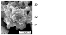
- FIG. 2 is an SEM image of silicon dioxide-carbon composite secondary particles contained in a negative electrode active material for a non-aqueous electrolyte secondary battery of the present invention. It is an exploded view showing an example of the structure of the secondary battery (laminate film type) using the negative electrode for nonaqueous electrolyte secondary batteries of this invention.
- non-aqueous electrolyte secondary batteries using this siliceous material are expected to have cycle characteristics and safety similar to those of non-aqueous electrolyte secondary batteries using carbon materials
- non-aqueous electrolyte secondary batteries using carbon materials are desired.
- a negative electrode material showing cycle stability and safety equivalent to those of the secondary battery has not been proposed.
- the silicon compound containing oxygen has a lower initial efficiency than the carbon material, so that the battery capacity has been limited to that extent.
- silicon oxide is used as the negative electrode material of the secondary battery, there is a problem that the battery performance is deteriorated due to non-conductive silicon dioxide mixed during manufacture.
- a negative electrode active material for a non-aqueous electrolyte secondary battery containing negative electrode active material particles, wherein the negative electrode active material particles have a silicon compound (SiO x : 0.5) in which a carbon film is formed on at least a part of the surface.
- the negative electrode active material contains 2% by mass or less of silicon dioxide particles, and a silicon dioxide-carbon containing a plurality of the silicon dioxide particles and carbon As long as it contains composite secondary particles, when this negative electrode active material is used as an active material for a non-aqueous electrolyte secondary battery, it has a high battery capacity and good cycle characteristics and initial charge / discharge capacity. As a result, they have reached the present invention.
- FIG. 1 shows a cross-sectional configuration of a negative electrode for a nonaqueous electrolyte secondary battery (hereinafter sometimes simply referred to as “negative electrode”) according to an embodiment of the present invention.
- the negative electrode 10 is configured to have a negative electrode active material layer 12 on a negative electrode current collector 11.
- the negative electrode active material layer 12 may be provided on both surfaces or only one surface of the negative electrode current collector 11. Furthermore, the negative electrode current collector 11 may be omitted as long as the negative electrode active material of the present invention is used.
- the negative electrode current collector 11 is an excellent conductive material and is made of a material that is excellent in mechanical strength.
- Examples of the conductive material that can be used for the negative electrode current collector 11 include copper (Cu) and nickel (Ni). This conductive material is preferably a material that does not form an intermetallic compound with lithium (Li).
- the negative electrode current collector 11 preferably contains carbon (C) or sulfur (S) in addition to the main element. This is because the physical strength of the negative electrode current collector is improved.
- the current collector contains the above-described element, there is an effect of suppressing electrode deformation including the current collector.
- content of said content element is not specifically limited, Especially, it is preferable that it is 100 mass ppm or less. This is because a higher deformation suppressing effect can be obtained.
- the surface of the negative electrode current collector 11 may be roughened or not roughened.
- the roughened negative electrode current collector is, for example, a metal foil subjected to electrolytic treatment, embossing treatment, or chemical etching.
- the non-roughened negative electrode current collector is, for example, a rolled metal foil.
- the negative electrode active material layer 12 includes a plurality of negative electrode active material particles capable of occluding and releasing lithium ions, and may further include other materials such as a negative electrode binder and a conductive additive in terms of battery design. .
- the negative electrode active material for a nonaqueous electrolyte secondary battery of the present invention is a material constituting the negative electrode active material layer 12.
- the negative electrode active material for a nonaqueous electrolyte secondary battery of the present invention has a silicon compound (SiO x : 0.5 ⁇ x ⁇ 1.6) having a carbon film formed on at least a part of the surface. Contains active material particles. Further, since this negative electrode active material contains 2% by mass or less of silicon dioxide particles and contains a plurality of silicon dioxide particles and silicon dioxide-carbon composite secondary particles formed of carbon, It is possible to suppress a decrease in battery performance due to silicon dioxide contamination.
- the negative electrode active material particles in the present invention contain silicon compound particles containing a silicon compound capable of inserting and extracting lithium ions.
- the negative electrode active material particles of the negative electrode active material of the present invention have a silicon oxide material containing a silicon compound (SiO x : 0.5 ⁇ x ⁇ 1.6), and x is the composition of the silicon compound. A value close to 1 is preferable. This is because high cycle characteristics can be obtained.
- the siliceous material composition in the present invention does not necessarily mean 100% purity, and may contain a trace amount of impurity elements.
- silicon compound particles containing a silicon compound (SiO x ) include a carbon coating on at least a part of the surface, and therefore have an appropriate conductivity. Sex can be obtained.
- the negative electrode active material in this invention contains 2 mass% or less of silicon dioxide particles.
- the size of the silicon dioxide particles is not particularly limited, but the size is preferably 1 ⁇ m or less because the raw material used for producing the silicon compound (SiO x ) particles is mixed therein. This is because the smaller the silicon dioxide particles, the larger the contact area with the metal silicon particles, which are another raw material for producing silicon compound (SiO x ) particles, and the silicon compound (SiO x ) generation reaction. This is because the efficiency can be improved.
- the mass fraction of the silicon dioxide particles with respect to the entire negative electrode active material can be confirmed by separating the silicon dioxide particles and the silicon compound (SiO x ) by airflow classification. This measurement can be performed in a state in which the silicon dioxide particles and the silicon compound (SiO x ) particles are respectively coated with carbon, and the silicon dioxide particles form composite secondary particles.
- the mass fraction of the silicon dioxide particles with respect to the whole negative electrode active material is calculated by combining airflow classification and morphology observation / elemental analysis. be able to.
- the mass fraction of silicon dioxide particles is calculated according to the following procedure. First, airflow classification is performed on the negative electrode active material powder, and the mass of each of the coarse powder and fine powder is measured. Next, for each of the coarse powder and fine powder, morphological observation and elemental analysis are performed on a large number of randomly selected particles using SEM-EDX (scanning electron microscope-energy dispersive X-ray spectroscopy). At this time, whether the silicon dioxide particles are identified from the elemental composition of each particle, the number fraction of the silicon dioxide particles is obtained, and then the volume fraction of each particle is obtained to calculate the mass fraction of the silicon dioxide particles. can do.
- SEM-EDX scanning electron microscope-energy dispersive X-ray spectroscopy
- the classification point it is preferable to adjust the classification point so that the silicon dioxide particles are concentrated on either the coarse powder or the fine powder by airflow classification. This is because the calculated mass fraction of silicon dioxide particles becomes more accurate as the concentration of the silicon dioxide particles after classification increases.
- the volume of each particle can be obtained by, for example, a method of calculating the equivalent circle diameter from the projected area of each particle and calculating by spherical approximation.
- the composite secondary particles desirably include silicon compound (SiO x ) particles. If the composite secondary particles contain silicon compound particles having a capacity in this way, local variations in capacity and potential during battery charging and discharging can be suppressed, and lithium metal deposition can be suppressed. Cycle characteristics can be obtained.
- elemental analysis can be used to confirm the silicon compound (SiO x ) in the composite secondary particles.
- elemental analysis methods include methods using SEM-EDX, TEM-EDX (transmission electron microscope-energy dispersive X-ray spectroscopy), and the like. Specifically, for each primary particle identified by morphological observation using SEM / TEM, the composition ratio of Si element and O element is calculated using EDX measurement to distinguish between silicon dioxide and silicon compound. can do.
- the average particle size of the composite secondary particles is 1 ⁇ m or more and 15 ⁇ m or less at this time. If it is 1 micrometer or more, since a specific surface area is not so large, decomposition
- the major axis L and the minor axis D of the composite secondary particle satisfy the relationship of 1 ⁇ L / D ⁇ 5. This is because, within such a range, the composite secondary particles are likely to be accommodated between the negative electrode active material particles and have an appropriate contact area with the negative electrode active material particles, so that good conductivity can be obtained.
- the major axis L and the minor axis D are defined by morphological observation with SEM or TEM. Specifically, the length of the straight line connecting the two most distant points in the projection plane of the observed composite secondary particles is the major axis, perpendicular to the major axis, and the straight line passing through the midpoint of the major axis is within the projection plane. The length of the portion at is the minor axis.
- the silicon dioxide particles constituting the composite secondary particles are substantially spherical.
- substantially spherical means that the circularity Lc / Lp defined by the ratio of the circumferential length Lp of the cross-section when taking the cross-section of the particle to the circumferential length Lc of the circle equal to the cross-sectional area of the particle is Means greater than 0.95. If the silicon dioxide particles are spherical, the specific surface area is small, and the composite secondary particles containing the silicon dioxide particles as a constituent also have a small specific surface area.
- a spherical surface having a smaller curvature than that of a square shape or the like increases the possibility of contact with the negative electrode active material particles, and a large contact area can be obtained. Therefore, good conductivity can be obtained while suppressing the reaction with the electrolytic solution on the surface of the composite secondary particles to a small amount.
- Examples of the method for confirming the shape of the silicon dioxide particles include morphological observation using AFM (atomic force microscope), SEM-EDX, TEM-EDX, and the like.
- the ratio of carbon to the entire composite secondary particle is 60 at% or more. With such a content, the electronic conductivity of the composite secondary particles can be improved.
- the ratio of carbon to the entire composite secondary particle can be calculated from elemental analysis or the like.
- the elemental analysis method include a method using a carbon amount measuring device (combustion in oxygen stream-infrared absorption method), XPS (X-ray photoelectron spectroscopy), SEM-EDX, TEM-EDX and the like.
- the coverage of carbon on the surface of the composite secondary particle is 30% or more and the average film thickness of the carbon coating is 30 nm or more. If the coverage of carbon on the surface of the composite secondary particle is 30% or more, the probability that carbon instead of silicon dioxide will come into contact at the contact surface between the composite secondary particle and the negative electrode active material particle is increased. Can be increased. Moreover, if the average film thickness of the carbon coating on the surface of the composite secondary particle is 30 nm or more, good electron conductivity can be obtained.
- elemental analysis of the surface can be used.
- surface elemental analysis methods include XPS and SEM-EDX.
- TEM can be used, for example.
- the composite secondary particle is 2% by mass or less based on the total mass of the negative electrode active material. This is because, with such a composite secondary particle content, since a small amount of composite secondary particles with a small capacity is small, a negative electrode active material with a larger capacity can be obtained.
- the mass fraction of the composite secondary particles with respect to the total mass of the negative electrode active material can be calculated by combining airflow classification and elemental analysis, for example, in the same manner as the method for obtaining the mass fraction of silicon dioxide particles described above.
- the carbon film formed on the surface of the silicon compound particles in the Raman spectrum analysis have a scattering peak at 1330 cm -1 and 1580 cm -1, their intensity ratio I 1330 / I 1580 is 0.7 ⁇ I 1330 It is preferable that the relationship / I 1580 ⁇ 2.0 is satisfied.
- the ratio of the carbon material having a diamond structure (carbon film or carbon-based material) and the carbon material having a graphite structure can be obtained from a Raman spectrum obtained by microscopic Raman analysis (that is, Raman spectrum analysis). That is, the diamond Raman shift 1330 cm -1, graphite Raman shift indicates a sharp peak at 1580 cm -1, to obtain the percentage of carbon material with a carbon material and a graphite structure with a simple diamond structure by the intensity ratio Can do.
- Diamond has high strength, high density, and high insulation, and graphite has excellent electrical conductivity. Therefore, the carbon coating satisfying the above range of the intensity ratio I 1330 / I 1580 is optimized for the above-mentioned characteristics of diamond and graphite, and as a result, prevents electrode destruction due to expansion / contraction of the electrode material during charge / discharge. And a negative electrode material having a good conductive network.
- Examples of a method for forming a carbon coating on the surface of silicon compound particles include a method of coating silicon compound particles with a carbon material (carbon compound) such as graphite.
- a fragment of a C y H z compound is detected by TOF-SIMS, and y and z are 6 ⁇ y ⁇ 2, 2y + 2 ⁇ z ⁇ as the fragment of the C y H z compound. It is preferable that at least a part satisfying the range of 2y-2 is detected.
- the fragment of the C y H z compound is derived from a carbon film grown on the surface of the silicon compound particles by the CVD method or the like, and CMC (carboxymethyl cellulose) or polyimide can be used as long as such a compound fragment is detected.
- the compatibility with the binder (binder) such as the above is improved, and as a result, the battery characteristics are improved. Further, if the surface state of a fragment of the C y H z type compound satisfying the above range is detected, binder compatibility with becomes better (binder), it is possible to further improve the battery characteristics resulting .
- Detection of a C y H z -based compound fragment can be performed, for example, under the following conditions.
- Sample Compacted pellet
- the carbon coating on the surface of the silicon compound particles has a weight average molecular weight of 400 or more and 5000 or less as measured by gel permeation chromatography based on polystyrene standards, and contains a carbon compound that is soluble in a hydrocarbon solvent. Is preferred. Moreover, it is preferable that content of the carbon-type compound is 2 mass ppm or more and 6000 mass ppm or less with respect to the total mass of a silicon compound particle. If the weight average molecular weight of the carbon compound is 400 or more, elution of the carbon compound to the electrolytic solution can be suppressed, and if the weight average molecular weight is 5000 or less, a decrease in conductivity of the carbon film can be suppressed.
- the weight average molecular weight is more preferably 600 or more and 3000 or less. This is because, within such a range, the effect of suppressing the decomposition of the electrolytic solution during charge / discharge is particularly exhibited while maintaining the conductivity of the conductive carbon film.
- thermal decomposition CVD chemical vapor deposition
- the precursor is thermally decomposed and dehydrogenated while repeating continuous cleavage and generation of carbon-hydrogen bonds at high temperatures.
- This continuous reaction occurs not only on the particle surface forming the carbon coating but also in the gas phase.
- a part of the continuous reaction product in the gas phase can be adsorbed on the carbon film on the particle surface as a solvent-soluble carbon compound.
- hydrocarbon solvent examples include pentane, hexane, cyclohexane, benzene, toluene, xylene, mesitylene, and octane.
- the content of the carbon coating on the surface of the silicon compound particles is preferably 2% by mass or more and 20% by mass or less with respect to the total mass of the silicon compound particles and the carbon coating.
- the electrical conductivity can be reliably improved. Moreover, if the content rate of this carbon film is 20 mass% or less, battery characteristics will improve and battery capacity will become large. If it has a carbon film in such a ratio, a high capacity
- the lower the silicon crystallinity in the silicon compound particles the better.
- the full width at half maximum (2 ⁇ ) of a diffraction peak caused by a silicon (111) crystal plane obtained by X-ray diffraction of silicon compound particles is 1.2 ° or more, and a crystallite corresponding to the crystal plane It is desirable that the size is 7.5 nm or less.
- the presence of a silicon compound having low silicon crystallinity can improve battery characteristics.
- a stable Li compound can be generated inside or on the surface of the silicon compound or both.
- the median diameter of the silicon compound particles is not particularly limited, but is preferably 0.5 ⁇ m or more and 20 ⁇ m or less. This is because, within this range, lithium ions are easily occluded and released during charging and discharging, and the particles are difficult to break. If the median diameter is 0.5 ⁇ m or more, the surface area does not increase, so that the battery irreversible capacity can be reduced. On the other hand, if the median diameter is 20 ⁇ m or less, it is preferable because the particles are difficult to break and a new surface is difficult to appear. In addition, the temperature of the measurement environment in the median diameter measurement is 25 ° C.
- the negative electrode active material layer may contain a negative electrode conductive additive in addition to the negative electrode active material.
- a negative electrode conductive additive include one or more of graphite such as carbon black, acetylene black, and scaly graphite, ketjen black, carbon nanotube, and carbon nanofiber.
- These conductive assistants are preferably in the form of particles having a median diameter smaller than that of the silicon compound particles.
- the negative electrode active material layer 12 as shown in FIG. 1 may further contain a carbon material (carbon-based active material) in addition to the negative electrode active material of the present invention.
- a carbon material carbon-based active material
- the electrical resistance of the negative electrode active material layer 12 can be reduced, and the expansion stress associated with charging can be reduced.
- the carbon-based active material include pyrolytic carbons, cokes, glassy carbon fibers, organic polymer compound fired bodies, and carbon blacks.
- the negative electrode of the present invention preferably has a silicon compound ratio of 4% by mass or more based on the total mass of the carbon-based active material and the silicon compound particles.
- the initial efficiency and capacity retention rate do not decrease.
- the upper limit of this content is less than 90 mass%.
- the negative electrode active material layer 12 is formed by, for example, a coating method.
- the coating method is a method in which a negative electrode active material particle and the above-described binder, and the like, and a conductive additive and a carbon material are mixed as necessary, and then dispersed and coated in an organic solvent or water.
- a method for producing the negative electrode of the present invention will be described. First, a step of producing silicon compound particles containing a silicon compound represented by the general formula SiO x (0.5 ⁇ x ⁇ 1.6), and a step of covering at least a part of the surface of the silicon compound particles with a carbon film And a step of forming a silicon dioxide-carbon composite secondary particle containing a plurality of silicon dioxide particles and carbon, and containing 2% by mass or less of silicon dioxide particles from the produced negative electrode active material. In addition, a negative electrode active material is produced by selecting those containing silicon dioxide-carbon composite secondary particles.
- a negative electrode active material is mixed with a conductive support agent, a binder, and a solvent, and a slurry is obtained. Next, the slurry is applied to the surface of the negative electrode current collector and dried to form a negative electrode active material layer.
- the negative electrode is manufactured, for example, by the following procedure.
- a raw material that generates silicon oxide gas (also referred to as a vaporization starting material) is heated in the temperature range of 900 ° C. to 1600 ° C. in the presence of an inert gas or under reduced pressure to generate silicon oxide gas.
- the raw material is a mixture of metal silicon powder and silicon dioxide powder, and considering the surface oxygen of the metal silicon powder and the presence of trace amounts of oxygen in the reactor, the mixing molar ratio is 0.8 ⁇ metal silicon powder / It is desirable that the silicon dioxide powder is in the range of ⁇ 1.3.
- Si crystallites in the silicon compound particles are controlled by changing the charging range and vaporization temperature, and by heat treatment after generation. The generated gas is deposited on the precipitation plate.
- the mixing amount of the raw silicon dioxide powder is controlled by controlling the position of the precipitation plate.
- the deposit is taken out with the temperature inside the silicon oxide reactor lowered to 100 ° C. or lower, and pulverized and powdered using a ball mill, a jet mill or the like.
- the powder material is mostly SiO x (0.5 ⁇ x ⁇ 1.6), but partly silicon dioxide (SiO 2). ) Particles are mixed in.
- pyrolysis CVD As a method for forming a carbon film on the surface layer of the obtained powder material, pyrolysis CVD is desirable.
- a furnace in which silicon oxide powder is set is filled with a hydrocarbon gas to raise the furnace temperature.
- the decomposition temperature is not particularly limited, but is particularly preferably 1200 ° C. or lower, and more preferably 950 ° C. or lower. This is because it is possible to suppress disproportionation of the active material particles.
- a carbon film satisfying a desired peak intensity ratio I 1330 / I 1580 in the Raman spectrum is formed on the surface layer of the powder material. be able to.
- the hydrocarbon gas used in the thermal decomposition CVD is not particularly limited, but 3 ⁇ n is desirable in the C n H m composition. This is because the manufacturing cost can be lowered and the physical properties of the decomposition product are good.
- silicon dioxide-carbon composite secondary particles containing a plurality of silicon dioxide particles and carbon are formed.
- the above-described thermal decomposition CVD can be mentioned.
- the pressure, temperature, powder input amount, hydrocarbon gas composition, etc. in the furnace By adjusting the pressure, temperature, powder input amount, hydrocarbon gas composition, etc. in the furnace, the particle size and carbon content of the composite secondary particles, the mass fraction of the composite secondary particles with respect to the total amount of active material, etc. are controlled. it can.
- the step of forming the carbon film on the surface layer of the silicon compound particles and the step of forming the composite secondary particles may be performed simultaneously or sequentially, but are preferably performed simultaneously. This is because it is easier to carry out at the same time and manufacturing at a low cost is possible.
- the step of controlling the crystallinity of the silicon compound is performed in a non-atmospheric atmosphere and at a temperature higher than that of pyrolytic CVD. You may heat-process in.
- the negative electrode active material contains 2% by mass or less of silicon dioxide particles by using airflow classification and morphological observation such as SEM-EDX, and Whether or not composite secondary particles are included is evaluated.
- the selection of the negative electrode active material is not necessarily performed every time the negative electrode active material is produced.
- the mass fraction of silicon dioxide and the presence / absence of composite secondary particles are once evaluated, and the silicon dioxide particles are contained in an amount of 2% by mass or less. If the production conditions are found and selected so as to contain the composite secondary particles, then the negative electrode material can be produced under the same conditions as the selected conditions.
- the negative electrode active material powder is continuously supplied and discharged. It is preferable to use a furnace.
- the heating furnace set to the heating temperature described above is the process atmosphere described above, the step of forming a carbon film while charging the negative electrode active material powder and holding in the heating furnace for a certain time, and the composite secondary particles
- a system that performs the forming step at the same time and then takes out the treated negative electrode active material powder is preferable.
- a roller hearth kiln and a rotary kiln can be applied.
- a rotary kiln is particularly suitable from the viewpoint of high productivity.
- Lithium ion secondary battery> a lithium ion secondary battery using the above-described negative electrode for a nonaqueous electrolyte secondary battery will be described.
- a laminated film type secondary battery 30 shown in FIG. 3 is one in which a wound electrode body 31 is accommodated mainly in a sheet-like exterior member 35. This wound body has a separator between a positive electrode and a negative electrode and is wound. There is also a case where a separator is provided between the positive electrode and the negative electrode and a laminate is accommodated.
- the positive electrode lead 32 is attached to the positive electrode
- the negative electrode lead 33 is attached to the negative electrode.
- the outermost peripheral part of the electrode body is protected by a protective tape.
- the positive and negative electrode leads are led out in one direction from the inside of the exterior member 35 to the outside, for example.
- the positive electrode lead 32 is formed of a conductive material such as aluminum
- the negative electrode lead 33 is formed of a conductive material such as nickel or copper.
- the exterior member 35 is a laminate film in which, for example, a fusion layer, a metal layer, and a surface protective layer are laminated in this order.
- the laminate film is formed by fusing two films so that the fusion layer faces the electrode body 31.
- the outer peripheral edge portions in the adhesion layer are bonded together with an adhesive or the like.
- the fused part is, for example, a film such as polyethylene or polypropylene, and the metal part is aluminum foil or the like.
- the protective layer is, for example, nylon.
- An adhesion film 34 is inserted between the exterior member 35 and the positive and negative electrode leads to prevent intrusion of outside air.
- This material is, for example, polyethylene, polypropylene, or polyolefin resin.
- the positive electrode has, for example, a positive electrode active material layer on both sides or one side of the positive electrode current collector, similarly to the negative electrode 10 of FIG.
- the positive electrode current collector is made of, for example, a conductive material such as aluminum.
- the positive electrode active material layer includes one or more positive electrode materials capable of occluding and releasing lithium ions, and includes other materials such as a binder, a conductive additive, and a dispersant depending on the design. You can leave. In this case, details regarding the binder and the conductive additive are the same as, for example, the negative electrode binder and the negative electrode conductive additive already described.
- a lithium-containing compound is desirable.
- the lithium-containing compound include a composite oxide composed of lithium and a transition metal element, or a phosphate compound having lithium and a transition metal element.
- compounds having at least one of nickel, iron, manganese, and cobalt are preferable.
- These chemical formulas are represented by, for example, Li x M 1 O 2 or Li y M 2 PO 4 .
- M 1 and M 2 represent at least one transition metal element.
- the values of x and y vary depending on the battery charge / discharge state, but are generally expressed as 0.05 ⁇ x ⁇ 1.10 and 0.05 ⁇ y ⁇ 1.10.
- Examples of the composite oxide having lithium and a transition metal element include lithium cobalt composite oxide (Li x CoO 2 ), lithium nickel composite oxide (Li x NiO 2 ), and phosphoric acid having lithium and a transition metal element.
- Examples of the compound include a lithium iron phosphate compound (LiFePO 4 ) and a lithium iron manganese phosphate compound (LiFe 1-u Mn u PO 4 (0 ⁇ u ⁇ 1)). This is because, when these positive electrode materials are used, a high battery capacity can be obtained and excellent cycle characteristics can be obtained.
- the negative electrode has the same configuration as the above-described negative electrode 10 for a lithium ion secondary battery in FIG. 1.
- the negative electrode has negative electrode active material layers 12 on both surfaces of the current collector 11.
- the negative electrode preferably has a negative electrode charge capacity larger than the electric capacity (charge capacity as a battery) obtained from the positive electrode active material agent. This is because the deposition of lithium metal on the negative electrode can be suppressed.
- the positive electrode active material layer is provided on a part of both surfaces of the positive electrode current collector, and the negative electrode active material layer is also provided on a part of both surfaces of the negative electrode current collector.
- the negative electrode active material layer provided on the negative electrode current collector is provided with a region where there is no opposing positive electrode active material layer. This is for a stable battery design.
- the non-opposing region that is, the region where the negative electrode active material layer and the positive electrode active material layer are not opposed to each other, there is almost no influence of charge / discharge. Therefore, the state of the negative electrode active material layer is maintained as it is immediately after formation. Accordingly, the composition and the like of the negative electrode active material can be examined accurately with good reproducibility without depending on the presence or absence of charge / discharge.
- the separator isolates the positive electrode and the negative electrode, and allows lithium ions to pass through while preventing current short-circuiting due to contact between both electrodes.
- This separator is formed of, for example, a porous film made of synthetic resin or ceramic, and may have a laminated structure in which two or more kinds of porous films are laminated.
- the synthetic resin include polytetrafluoroethylene, polypropylene, and polyethylene.
- Electrode At least a part of the active material layer or the separator is impregnated with a liquid electrolyte (electrolytic solution).
- This electrolytic solution has an electrolyte salt dissolved in a solvent, and may contain other materials such as additives.
- a nonaqueous solvent for example, a nonaqueous solvent can be used.
- the non-aqueous solvent include ethylene carbonate, propylene carbonate, butylene carbonate, dimethyl carbonate, diethyl carbonate, ethyl methyl carbonate, methyl propyl carbonate, 1,2-dimethoxyethane, or tetrahydrofuran.
- ethylene carbonate, propylene carbonate, dimethyl carbonate, diethyl carbonate, and ethyl methyl carbonate it is desirable to use at least one of ethylene carbonate, propylene carbonate, dimethyl carbonate, diethyl carbonate, and ethyl methyl carbonate. This is because better characteristics can be obtained. In this case, more advantageous characteristics can be obtained by combining a high viscosity solvent such as ethylene carbonate or propylene carbonate and a low viscosity solvent such as dimethyl carbonate, ethyl methyl carbonate or diethyl carbonate. This is because the dissociation property and ion mobility of the electrolyte salt are improved.
- the solvent additive contains an unsaturated carbon bond cyclic carbonate. This is because a stable film is formed on the surface of the negative electrode during charging and discharging, and the decomposition reaction of the electrolytic solution can be suppressed.
- unsaturated carbon bond cyclic ester carbonate include vinylene carbonate and vinyl ethylene carbonate.
- sultone cyclic sulfonic acid ester
- solvent additive examples include propane sultone and propene sultone.
- the solvent preferably contains an acid anhydride. This is because the chemical stability of the electrolytic solution is improved.
- the acid anhydride include propanedisulfonic acid anhydride.
- the electrolyte salt can contain, for example, any one or more of light metal salts such as lithium salts.
- the lithium salt include the following materials. Examples thereof include lithium hexafluorophosphate (LiPF 6 ) and lithium tetrafluoroborate (LiBF 4 ).
- the content of the electrolyte salt is preferably 0.5 mol / kg or more and 2.5 mol / kg or less with respect to the solvent. This is because high ionic conductivity is obtained.
- a positive electrode is manufactured using the positive electrode material described above.
- a positive electrode active material and, if necessary, a binder, a conductive additive and the like are mixed to form a positive electrode mixture, and then dispersed in an organic solvent to form a positive electrode mixture slurry.
- the mixture slurry is applied to the positive electrode current collector with a coating apparatus such as a die coater having a knife roll or a die head, and dried with hot air to obtain a positive electrode active material layer.
- the positive electrode active material layer is compression molded with a roll press or the like. At this time, heating may be performed. Further, compression and heating may be repeated a plurality of times.
- a negative electrode is produced by forming a negative electrode active material layer on the negative electrode current collector using the same operating procedure as the production of the negative electrode 10 for lithium ion secondary batteries described above.
- a positive electrode and a negative electrode are produced by the same production procedure as described above.
- each active material layer can be formed on both surfaces of the positive electrode and the negative electrode current collector.
- the active material application length of both surface portions may be shifted in either electrode (see FIG. 1).
- the positive electrode lead 32 is attached to the positive electrode current collector and the negative electrode lead 33 is attached to the negative electrode current collector by ultrasonic welding or the like. Then, a positive electrode and a negative electrode are laminated
- the adhesion film 34 is inserted between the positive electrode lead 32 and the negative electrode lead 33 and the exterior member 35. A predetermined amount of the adjusted electrolytic solution is introduced from the release portion, and vacuum impregnation is performed. After impregnation, the release part is bonded by a vacuum heat fusion method.
- the laminated film type secondary battery 30 can be manufactured as described above.
- Example 1-1 The laminate film type secondary battery 30 shown in FIG. 3 was produced by the following procedure.
- the positive electrode active material is a mixture of 95 parts by mass of LiCoO 2 which is a lithium cobalt composite oxide, 2.5 parts by mass of a positive electrode conductive additive, and 2.5 parts by mass of a positive electrode binder (polyvinylidene fluoride: Pvdf).
- a positive electrode mixture was obtained.
- the positive electrode mixture was dispersed in an organic solvent (N-methyl-2-pyrrolidone: NMP) to obtain a paste slurry.
- the slurry was applied to both surfaces of the positive electrode current collector with a coating apparatus having a die head, and dried with a hot air drying apparatus. At this time, the positive electrode current collector had a thickness of 15 ⁇ m.
- compression molding was performed with a roll press.
- a negative electrode was created.
- a vaporization starting material mixed with metallic silicon and silicon dioxide was placed in a reaction furnace, deposited in a vacuum of 10 Pa, sufficiently cooled, and then the deposit was taken out and pulverized with a ball mill. The diameter was adjusted.
- pyrolysis CVD was performed to obtain a carbon coating and composite secondary particles.
- a thermal decomposition CVD apparatus a rotary kiln equipped with a rotary cylindrical furnace having a reaction gas inlet and a carrier gas inlet and having an inner diameter of 200 mm and a length of 3 m was prepared. At this time, the inclination angle in the furnace major axis direction was set to 1 degree. Thereafter, 20 kg of powder was charged into the tank, and the temperature in the furnace was raised to 1050 ° C. and held in a nitrogen atmosphere.
- the raw material particles were charged into the furnace at a rate of 1.0 Kg / h, and further 12 L / min of methane as a reaction gas and 15 L / min of nitrogen as a carrier gas were introduced.
- the rotation speed of the furnace was 1 rpm, and the furnace pressure was adjusted to be 20 Pa positive pressure with respect to atmospheric pressure.
- a carbon film was formed on the surface of silicon compound (SiO x ) particles, and at the same time, composite secondary particles were obtained.
- the value x of the silicon compound SiO x was 0.5, and the median diameter D 50 of the silicon compound was 5.4 ⁇ m.
- the silicon compound particles have a half-width (2 ⁇ ) of a diffraction peak due to the (111) crystal plane obtained by X-ray diffraction of 1.85 °, and the crystallite size due to the crystal plane (111) is It was 4.72 nm.
- the carbon compound (A2) was dissolved in tetrahydrofuran, GPC measurement was performed, and the molecular weight was calculated from a calibration curve prepared from a polystyrene standard. Since the GPC chart showed several peaks, it was found to be a mixture of components having different molecular weights. The weight average molecular weight obtained from all peaks was 840.
- the mass fraction of the negative electrode active material powder was 0.75% by mass for silicon dioxide particles and 1.8% by mass for composite secondary particles, respectively.
- An SEM image of the obtained silicon dioxide-carbon composite secondary particles is shown in FIG. In FIG.
- a silicon dioxide-carbon composite secondary particle 20 (which is an aggregate having a diameter of about 7 ⁇ m in FIG. 2) includes silicon dioxide particles 21 and silicon compound (SiO x ) particles 22.
- the silicon dioxide particles 21 and the silicon compound (SiO x ) particles 22 are each coated with carbon.
- the negative electrode active material particles the negative electrode binder 1 (polyacrylic acid), the negative electrode binder 2 (carboxymethylcellulose), the negative electrode binder 3 (SBR (styrene butadiene rubber)), and the conductive auxiliary agent 1 (scale pieces) Graphite), conductive auxiliary agent 2 (acetylene black), conductive auxiliary agent 3 (carbon nanotubes) at a dry mass ratio of 90: 2: 2.5: 2.5: 1: 0.5: 1.5
- the negative electrode mixture slurry was applied to both surfaces of the negative electrode current collector with a coating apparatus and then dried.
- it was baked at 90 ° C. for 1 hour in a vacuum atmosphere. Thereby, a negative electrode active material layer is formed.
- a solvent (4-fluoro-1,3-dioxolan-2-one (FEC), ethylene carbonate (EC) and dimethyl carbonate (DMC)) is mixed, and then an electrolyte salt (lithium hexafluorophosphate: LiPF) is mixed. 6 ) was dissolved to prepare an electrolytic solution.
- FEC fluoro-1,3-dioxolan-2-one
- EC ethylene carbonate
- DMC dimethyl carbonate
- an electrolyte salt lithium hexafluorophosphate: LiPF
- a secondary battery was assembled as follows. First, an aluminum lead was ultrasonically welded to one end of the positive electrode current collector, and a nickel lead was welded to the negative electrode current collector. Subsequently, a positive electrode, a separator, a negative electrode, and a separator were laminated in this order and wound in the longitudinal direction to obtain a wound electrode body. The end portion was fixed with a PET protective tape. As the separator, a laminated film of 12 ⁇ m sandwiched between a film mainly composed of porous polyethylene and a film mainly composed of porous polypropylene was used.
- the outer peripheral edges except for one side were heat-sealed, and the electrode body was housed inside.
- the exterior member a nylon film, an aluminum foil, and an aluminum laminate film in which a polypropylene film was laminated were used.
- the prepared electrolyte was injected from the opening, impregnated in a vacuum atmosphere, and then heat-sealed and sealed.
- Example 1-1 A secondary battery was manufactured in the same manner as in Example 1-1 except that the amount of oxygen in the bulk of the silicon compound particles was adjusted. In this case, the amount of oxygen was adjusted by changing the ratio and temperature of the vaporized starting material.
- Table 1 shows the value of x of the silicon compound represented by SiO x in Examples 1-1 to 1-5 and Comparative Examples 1-1 and 1-2.
- the cycle characteristics were examined as follows. First, in order to stabilize the battery, charge / discharge was performed for 2 cycles in an atmosphere at 25 ° C., and the discharge capacity at the second cycle was measured. Subsequently, charge and discharge were performed until the total number of cycles reached 100, and the discharge capacity was measured each time. Finally, the discharge capacity at the 100th cycle was divided by the discharge capacity at the 2nd cycle and multiplied by 100 for% display, and the capacity maintenance rate (hereinafter, sometimes simply referred to as the maintenance rate) was calculated. As cycling conditions, a constant current density until reaching 4.3V, and charged at 2.5 mA / cm 2, current density 4.3V constant voltage at the stage of reaching the voltage of 4.3V is to 0.25 mA / cm 2 Charged until it reached. During discharging, discharging was performed at a constant current density of 2.5 mA / cm 2 until the voltage reached 3.0V.
- initial efficiency (initial discharge capacity / initial charge capacity) ⁇ 100.
- the ambient temperature was the same as when the cycle characteristics were examined.
- the charge / discharge conditions were 0.2 times the cycle characteristics. That is, a constant current density until reaching 4.3V, and charged at 0.5 mA / cm 2, at 4.3V constant voltage at the stage where the voltage reaches 4.3V until the current density reached 0.05 mA / cm 2
- the battery was charged and discharged at a constant current density of 0.5 mA / cm 2 until the voltage reached 3.0V.
- the maintenance rates and initial efficiency shown in the following Tables 1 to 10 do not contain a carbon-based active material such as natural graphite (for example, an average particle size of 20 ⁇ m), and are mainly composed of silicon compound particles having a carbon coating.
- the maintenance rate and initial efficiency when only the substance is used as the negative electrode active material, that is, the maintenance rate and initial efficiency of the silicon compound are shown. This depends only on changes in silicon compounds (oxygen content, crystallinity, median diameter change), carbon coating changes (content, film quality), and composite secondary particle changes (mass fraction, composition ratio, shape). The change in maintenance rate and initial efficiency could be measured.
- Example 2-1 to Example 2-4 Comparative Example 2-1 to Comparative Example 2-3
- a secondary battery was manufactured basically in the same manner as in Example 1-3.
- the silicon compound represented by SiO x the positional relationship between the vaporization starting material and the precipitation plate was changed, so that As shown in Table 2, the mass fraction of silicon dioxide particles, the presence or absence of composite secondary particles, and the presence or absence of silicon compound particles in the composite secondary particles were changed.
- Table 2 the results shown in Table 2 were obtained. .
- the silicon compounds containing the composite secondary particles of Examples 2-1 to 2-4 were compared with the silicon compounds not containing the composite secondary particles of Comparative Example 2-1 and Comparative Example 2-2. Good initial efficiency and capacity retention were obtained. Moreover, when the silicon dioxide particles were included in excess of 2% by mass, the initial efficiency and the capacity retention rate were deteriorated even if the composite secondary particles were included. Furthermore, when the silicon compound (SiO x ) particles were included in the composite secondary particles, the capacity retention rate was improved as compared with the case where no SiO x was included.
- Example 3-1 to Example 3-11 Secondary battery as in Example 1-3, except that the average particle diameter of the composite secondary particles contained in the negative electrode active material powder, the ratio L / D of the long diameter to the short diameter, and the shape of the silicon dioxide particles were changed was manufactured.
- the average particle diameter and L / D of the composite secondary particles contained in the negative electrode active material powder were controlled by adjusting the rotational speed and inclination of the rotary kiln during pyrolysis CVD.
- the shape of the silicon dioxide particles was controlled by changing the type of silicon dioxide raw material in the vaporization starting material.
- the cycle characteristics and initial charge / discharge characteristics of the secondary batteries of Examples 3-1 to 3-11 were examined. The results shown in Table 3 were obtained.
- Example 4-1 to Example 4-6 Comparative Example 4-1
- the carbon element ratio of the composite secondary particles in the negative electrode active material powder, the surface coverage, the coating carbon film thickness, and the mass fraction of the composite secondary particles relative to the total amount of the negative electrode active material powder were changed. Otherwise, the secondary battery was manufactured in the same manner as in Example 1-3.
- the carbon element ratio, surface coverage, coated carbon film thickness, and mass fraction of the composite secondary particles were controlled by adjusting the carbon source gas flow rate and carrier gas flow rate of the rotary kiln during pyrolysis CVD.
- Example 4-1 to Example 4-6 When the initial charge / discharge characteristics and cycle characteristics of the secondary battery of Comparative Example 4-1 were examined, the results shown in Table 4 were obtained.
- the initial efficiency and capacity retention rate deteriorated when the composite secondary particles did not contain carbon.
- the composite secondary particles contain carbon, good initial efficiency and capacity retention were observed, and better battery characteristics were obtained when the carbon element ratio was 60 at% or more.
- the carbon coverage of the composite secondary particles was 30% or more and the carbon film thickness was 30 nm or more, good initial efficiency and capacity maintenance rate were observed.
- the mass fraction of the composite secondary particles is in the range of 2% by mass or less, a favorable result is obtained as compared with the case of 2% by mass or more.
- Example 5-1 to Example 5-4 A secondary battery was fabricated in the same manner as in Example 1-3, except that the CyHz fragment detected from the carbon coating on the surface of the silicon compound particles in TOF-SIMS was changed as shown in Table 5.
- the CyHz fragment type was controlled by adjusting the gas type, CVD temperature, and post-CVD temperature used during pyrolysis CVD.
- the initial charge / discharge characteristics and cycle characteristics of the secondary batteries of Examples 5-1 to 5-4 were examined. The results shown in Table 5 were obtained.
- Example 6-1 to Example 6-11 A secondary battery as in Example 1-3, except that the weight average molecular weight and content of the carbon-based compound soluble in the hydrocarbon solvent contained in the carbon coating on the surface of the silicon compound particles were changed as shown in Table 6. Was manufactured. At this time, the weight average molecular weight and the content of the carbon-based compound were changed by changing the flow rate of the carbon source gas and the position of the introduction port, and the flow rate of the carrier gas and the location of the introduction port in the rotary kiln during thermal decomposition CVD. The initial charge / discharge characteristics and cycle characteristics of the secondary batteries of Examples 6-1 to 6-11 were examined. The results shown in Table 6 were obtained.
- Example 7-1 to Example 7-4 A secondary battery was manufactured in the same manner as in Example 1-3, except that the carbon mass fraction, the carbon layer thickness, and the carbon layer coverage contained on the surface of the silicon compound particles were changed as shown in Table 7. . Each content was changed by changing the processing time of pyrolysis CVD. The cycle characteristics and initial charge / discharge characteristics of the secondary batteries of Examples 7-1 to 7-4 were examined. The results shown in Table 7 were obtained.
- the initial efficiency and capacity retention rate are better characteristics.
- the content of the carbon coating on the surface of the silicon compound particles is 2% by mass or more, the electron conductivity of the silicon compound particles is good. Further, when the content of the carbon coating on the surface of the silicon compound particles is 20% by mass or less, the ion conductivity is good. Accordingly, when the content of the carbon coating on the surface of the silicon compound particles is in the above range, the capacity retention rate and the initial efficiency are good values.
- Example 9-1 to Example 9-8 A secondary battery was manufactured in the same manner as in Example 1-3 except that the crystallinity of the silicon region in the silicon compound particles was changed. The change in crystallinity can be controlled by performing heat treatment in a non-atmospheric atmosphere after pyrolysis CVD.
- Table 9 shows the half widths of the silicon-based active materials of Examples 9-1 to 9-8. In Example 9-8, the half-value width is calculated to be 20.221 °, but it is a result of fitting using analysis software, and a peak is not substantially obtained. Therefore, it can be said that the silicon-based active material of Example 9-8 is substantially amorphous.
- the cycle characteristics and initial charge / discharge characteristics of the secondary batteries of Examples 9-1 to 9-8 were examined. The results shown in Table 9 were obtained.
- Example 10-1 to Example 10-6 A secondary battery was manufactured in the same manner as in Example 1-3 except that the median diameter of the silicon compound particles was adjusted as shown in Table 10 as shown in Table 10. The median diameter was adjusted by changing the grinding time and classification conditions in the production process of the silicon compound particles. The initial charge / discharge characteristics and cycle characteristics of the secondary batteries of Examples 10-1 to 10-6 were examined. The results shown in Table 10 were obtained.
- Example 11-1 to 11-5 secondary batteries were manufactured basically in the same manner as in Example 1-3. However, a carbon-based active material (graphite) was further added as the negative electrode active material. It was. Here, the ratio of the content of the carbon-based active material in the negative electrode and the content of the silicon compound particles was fixed at 90:10 (mass ratio). That is, the ratio of the silicon compound particles to the total amount of the carbon-based active material and the silicon compound particles was 10% by mass.
- the present invention is not limited to the above embodiment.
- the above-described embodiment is an exemplification, and the present invention has substantially the same configuration as the technical idea described in the claims of the present invention, and any device that exhibits the same function and effect is the present invention. It is included in the technical scope of the invention.
Landscapes
- Chemical & Material Sciences (AREA)
- Chemical Kinetics & Catalysis (AREA)
- Electrochemistry (AREA)
- General Chemical & Material Sciences (AREA)
- Engineering & Computer Science (AREA)
- Inorganic Chemistry (AREA)
- Organic Chemistry (AREA)
- Materials Engineering (AREA)
- Composite Materials (AREA)
- Manufacturing & Machinery (AREA)
- Battery Electrode And Active Subsutance (AREA)
- Silicon Compounds (AREA)
Abstract
本発明は、負極活物質粒子を含む非水電解質二次電池用負極活物質であって、前記負極活物質粒子は、表面の少なくとも一部に炭素被膜を形成したケイ素化合物(SiOx:0.5≦x≦1.6)を含むケイ素化合物粒子を含有し、該負極活物質は、二酸化ケイ素粒子を2質量%以下含有しており、かつ、複数の該二酸化ケイ素粒子と炭素を含む二酸化ケイ素-炭素複合二次粒子を含むことを特徴とする非水電解質二次電池用負極活物質である。これにより、電池容量を増加させるとともに、サイクル特性、及び電池初期効率を向上させることが可能な非水電解質二次電池用負極活物質が提供される。
Description
本発明は、非水電解質二次電池用負極活物質、非水電解質二次電池用負極、及び非水電解質二次電池、並びに非水電解質二次電池用負極活物質の製造方法に関する。
近年、モバイル端末などに代表される小型の電子機器が広く普及しており、さらなる小型化、軽量化及び長寿命化が強く求められている。このような市場要求に対し、特に小型かつ軽量で高エネルギー密度を得ることが可能な二次電池の開発が進められている。この二次電池は、小型の電子機器に限らず、自動車などに代表される大型の電子機器、家屋などに代表される電力貯蔵システムへの適用も検討されている。
その中でも、リチウムイオン二次電池は小型かつ高容量化が行いやすく、また、鉛電池、ニッケルカドミウム電池よりも高いエネルギー密度が得られるため、大いに期待されている。
リチウムイオン二次電池は、正極及び負極、セパレータと共に電解液を備えている。この負極は充放電反応に関わる負極活物質を含んでいる。
負極活物質としては、炭素材料が広く使用されている一方で、最近の市場要求から、電池容量のさらなる向上が求められている。電池容量向上の要素として、負極活物質材として、ケイ素を用いることが検討されている。ケイ素の理論容量(4199mAh/g)は黒鉛の理論容量(372mAh/g)よりも10倍以上大きいため、電池容量の大幅な向上を期待できるからである。負極活物質材としてのケイ素材の開発はケイ素単体だけではなく、合金、酸化物に代表される化合物などについても検討されている。活物質形状は炭素材で標準的な塗布型から、集電体に直接堆積する一体型まで検討されている。
しかしながら、負極活物質としてケイ素を主原料として用いると、充放電時に負極活物質粒子が膨張収縮するため、主に負極活物質粒子の表層近傍で割れやすくなる。また、活物質内部にイオン性物質が生成し、負極活物質粒子が割れやすくなる。負極活物質表層が割れることで新生面が生じ、活物質の反応面積が増加する。この時、新生面において電解液の分解反応が生じるとともに、新生面に電解液の分解物である被膜が形成されるため電解液が消費される。このためサイクル特性が低下しやすくなる。
これまでに、電池初期効率やサイクル特性を向上させるために、ケイ素材を主材としたリチウムイオン二次電池用負極材料、電極構成についてさまざまな検討が成されている。
具体的には、良好なサイクル特性や高い安全性を得る目的で、気相法を用いケイ素及びアモルファス二酸化ケイ素を同時に堆積させている(例えば特許文献1参照)。また、高い電池容量や安全性を得るために、ケイ素酸化物粒子の表層に炭素材(電子伝導材)を設けている(例えば特許文献2参照)。更に、サイクル特性を改善するとともに高入出力特性を得るために、ケイ素及び酸素を含有する活物質を作製し、かつ集電体近傍での酸素比率が高い活物質層を形成している(例えば特許文献3参照)。また、サイクル特性を向上させるために、ケイ素活物質中に酸素を含有させ、平均酸素含有量が40at%以下であり(at%は、原子組成百分率を表す)、かつ集電体に近い場所で酸素含有量が多くなるように形成している(例えば、特許文献4参照)。
また、初回充放電効率を改善するためにSi相、SiO2、MyO金属酸化物を含有するナノ複合体を用いている(例えば特許文献5参照)。また、初回充放電効率を改善するためにLi含有物を負極に添加し、負極電位が高いところでLiを分解しLiを正極に戻すプレドープを行っている(例えば特許文献6参照)。
また、サイクル特性改善のため、SiOx(0.8≦x≦1.5、粒径範囲=1μm~50μm)と炭素材を混合し高温焼成している(例えば特許文献7参照)。また、サイクル特性改善のために、負極活物質中におけるケイ素に対する酸素のモル比を0.1~1.2とし、活物質と集電体との界面近傍における、ケイ素量に対する酸素量のモル比の最大値と最小値との差が0.4以下となる範囲で活物質の制御を行っている(例えば、特許文献8参照)。また、サイクル特性を改善させるために、ケイ素材表層にシラン化合物などの疎水層を形成している(例えば特許文献9参照)。また、サイクル特性改善のため、酸化ケイ素を用い、その表層に黒鉛被膜を形成することで導電性を付与している(例えば特許文献10参照)。特許文献10において、黒鉛被膜に関するRAMANスペクトルから得られるシフト値に関して、1330cm-1及び1580cm-1にブロードなピークが現れるとともに、それらの強度比I1330/I1580が1.5<I1330/I1580<3となっている。
また、サイクル特性改善のため、酸化ケイ素を用い、その表層に黒鉛被膜を形成することで導電性を付与している(例えば、特許文献11参照)。この場合、特許文献11では、黒鉛被膜に関するラマンスペクトルから得られるシフト値に関して、1330cm-1及び1580cm-1にブロードなピークが現れるとともに、それらの強度比I1330/I1580が1.5<I1330/I1580<3である。
また、高い電池容量、サイクル特性の改善のため、二酸化ケイ素中に分散されたケイ素微結晶相を有する粒子を用いている(例えば、特許文献12参照)。また、過充電、過放電特性を向上させるために、ケイ素と酸素の原子数比を1:y(0<y<2)と制御したケイ素酸化物を用いている(例えば、特許文献13参照)。
このような二次電池用負極材料として使用される酸化ケイ素は、原料であるケイ素粉末及び二酸化ケイ素粉末を反応炉内に供給し、不活性ガスもしくは減圧下で加熱して酸化珪素ガスを発生させ、その酸化珪素ガスを冷却して基体表面に析出させるといった方法で製造される(例えば、特許文献14参照)。
上述のように、近年、電子機器に代表される小型のモバイル機器は高性能化、多機能化がすすめられており、その主電源である非水電解質二次電池、特にリチウムイオン二次電池は電池容量の増加が求められている。この問題を解決する1つの手法として、理論容量の大きいケイ素材を主材として用いた負極からなる非水電解質二次電池の開発が行われているが、炭素材を用いた非水電解質二次電池と同等に近いサイクル特性は得られておらず、さらなる改善が求められている。
また、特許文献14に記載された酸化ケイ素の製造方法では、反応炉内から冷却室への酸化ケイ素ガスの流れに伴って、原料である二酸化ケイ素粉末の一部も冷却室側へ移動し、酸化ケイ素の析出物に混入する。したがって、二次電池の負極材として酸化ケイ素を用いた場合、非導電性の二酸化ケイ素を含むために電池性能が低下するという問題がある。
本発明は、上記問題点に鑑みてなされたものであって、電池容量を増加させ、サイクル特性、及び電池初期効率を向上させることが可能な非水電解質二次電池用負極活物質を提供することを目的とする。また、本発明は、その負極活物質を用いた非水電解質二次電池用負極、及びその負極を用いた非水電解質二次電池を提供することを目的とする。また、本発明は、そのような負極に用いることができる非水電解質二次電池用負極活物質粒子の製造方法を提供することを目的とする。
上記目的を達成するために、本発明は、負極活物質粒子を含む非水電解質二次電池用負極活物質であって、前記負極活物質粒子は、表面の少なくとも一部に炭素被膜を形成したケイ素化合物(SiOx:0.5≦x≦1.6)を含むケイ素化合物粒子を含有し、該負極活物質は、二酸化ケイ素粒子を2質量%以下含有しており、かつ、複数の該二酸化ケイ素粒子と炭素を含む二酸化ケイ素-炭素複合二次粒子を含むことを特徴とする非水電解質二次電池用負極活物質を提供する。
このように、本発明の負極活物質は、ケイ素化合物を含むケイ素化合物粒子を含有する負極活物質粒子(ケイ素系活物質粒子とも呼称する)を含むため、高い電池容量を有する。また、炭素被膜を含むため適度な導電性を持ち、容量維持率及び初回効率を向上できる。さらに、電子伝導性を持った二酸化ケイ素-炭素複合二次粒子(複合二次粒子とも呼称する)として二酸化ケイ素粒子を含むため、製造時の二酸化ケイ素混入による電池性能の低下を抑制することができる。
このとき、前記複合二次粒子が前記ケイ素化合物粒子を含むことが好ましい。
このように、電池容量を持つケイ素化合物粒子を複合二次粒子内に含むため、電池充放電時における容量及び電位の局所的なばらつきを抑えることができる。
このとき、前記複合二次粒子の平均粒径が1μm以上15μm以下であることが好ましい。
複合二次粒子の平均粒径が1μm以上であれば、比表面積がそれほど大きくないため、複合二次粒子表面での電解液との反応を少量に抑えることができる。また、複合二次粒子の平均粒径が15μm以下であれば、負極活物質粒子と適度な接触面積を持つため、良好な導電性を得ることができる。
このとき、前記複合二次粒子の長径Lと短径Dが、1≦L/D≦5という関係を満たすことが好ましい。
複合二次粒子の長径Lと短径Dが、上記の範囲内であれば、複合二次粒子が負極活物質粒子間に収まりやすく、負極活物質粒子と適度な接触面積を持つため、良好な導電性を得ることができる。
またこのとき、前記複合二次粒子を構成する二酸化ケイ素粒子の少なくとも一部は実質的に球状であることが好ましい。
このように二酸化ケイ素粒子が球状であれば、複合二次粒子を適度な比表面積に保ちながら、負極活物質粒子との間に大きな接触面積を得られるため、電解液との反応を抑えながら、良好な導電性を得ることができる。
このとき、前記複合二次粒子の全体に対する炭素の割合が60at%以上であることが好ましい。
このような炭素含有率であれば、複合二次粒子の電子伝導性を向上することができる。
このとき、前記複合二次粒子の表面における炭素の被覆率が30%以上であり、かつ平均の膜厚が30nm以上であることが好ましい。
このように、前記複合二次粒子の表面における炭素の被覆率が30%以上であれば、複合二次粒子と負極活物質粒子との接触面において、二酸化ケイ素ではなく炭素が接触する確率が上がるため、導電性を高めることができる。また、平均の膜厚が30nm以上であれば、良好な電子伝導性を得ることができる。
このとき、前記複合二次粒子は、負極活物質の総質量に対して2質量%以下であることが好ましい。
このような複合二次粒子の含有率であれば、容量の小さい複合二次粒子が少量であるため、容量のより大きい負極活物質を得ることができる。
このとき、前記ケイ素化合物粒子表面に形成された炭素被膜が、ラマンスペクトル分析において、1330cm-1と1580cm-1に散乱ピークを有し、それらの強度比I1330/I1580が0.7<I1330/I1580<2.0という関係を満たすことが好ましい。
このような強度比I1330/I1580を有するものであれば、炭素被膜に含まれる、ダイヤモンド構造を有する炭素材とグラファイト構造を有する炭素材との割合を最適化することができ、容量維持率や初回効率などの電池特性を向上できる。
このとき、前記炭素被膜は、TOF-SIMS(飛行時間型二次イオン質量分析法)によって、CyHz系化合物のフラグメントが検出され、該CyHz系化合物のフラグメントとして、y及びzが、6≧y≧2、2y+2≧z≧2y-2という範囲を満たすものが、前記炭素被膜の少なくとも一部に検出されることが好ましい。
このようなCyHz系化合物のフラグメントが検出される表面状態であれば、負極活物質と結着剤(バインダー)との相性が良くなり、結果として電池特性をより向上させることができる。
このとき、前記炭素被膜が、ポリスチレン標準によるゲルパーミエーションクロマトグラフィにて測定した重量平均分子量が400以上5000以下であり、かつ、炭化水素溶媒に可溶な炭素系化合物を含み、かつ、該炭素系化合物の含有量が、前記ケイ素化合物粒子の全質量に対して2質量ppm以上6000質量ppm以下であることが好ましい。
このような炭素系化合物を含む炭素被膜であれば、導電性を損なうことなく電解液の分解を抑制することができるため、高い充放電容量及び良好なサイクル特性が得られる負極活物質とすることができる。
このとき、前記炭素被膜の含有率が、前記ケイ素化合物粒子及び前記炭素被膜の合計質量に対し2質量%以上20質量%以下であることが好ましい。
このような割合で炭素被膜を有すれば、高容量のケイ素化合物を適切な割合で含むことができ、十分な電池容量を確保することができる。
このとき、本発明の負極活物質は、X線回折スペクトルにおいて、2θ=21.8°付近のピークの強度(Ia)と2θ=28.4°付近のピークの強度(Ib)の関係が、0.8≦Ib/Ia≦4.0であることが好ましい。
このようなX線回折スペクトルのピーク強度比を有すれば、適度な強度、安定性及び電子伝導性を兼ね備えた負極活物質とすることができる。
またこのとき、前記ケイ素化合物粒子が、X線回折により得られるケイ素(111)結晶面に起因する回折ピークの半値幅(2θ)が1.2°以上であると共に、その結晶面に対応する結晶子サイズが7.5nm以下であることが好ましい。
このような半値幅及び結晶子サイズを有するケイ素化合物は結晶性の低いものである。このように結晶性が低くSi結晶の存在量が少ないケイ素化合物粒子を用いることにより、負極活物質の電池特性を向上させることができる。
このとき、前記ケイ素化合物粒子のメディアン径は0.5μm以上20μm以下であることが好ましい。
このようなメディアン径のケイ素化合物粒子を含む負極活物質であれば、容量維持率を向上させることができる。
また、本発明は、上記の非水電解質二次電池用負極活物質と、炭素系活物質とを含むことを特徴とする非水電解質二次電池用負極を提供する。
このような非水電解質二次電池用負極であれば、負極の容量を増やしつつ、初回効率、容量維持率を向上することができる。
このとき、前記炭素系活物質と前記ケイ素化合物粒子の総質量に対する、前記ケイ素化合物粒子の割合が4質量%以上のものであることが好ましい。
このような負極であれば、電池の体積エネルギー密度を向上させることができるものとなる。
また、本発明は、上記の非水電解質二次電池用負極を用いたものであることを特徴とする非水電解質二次電池を提供する。
本発明の負極を用いた非水電解質二次電池は、高容量で、かつサイクル特性及び初回効率が良好なものとなる。
また、本発明は、負極活物質粒子を有する非水電解質二次電池用負極活物質の製造方法であって、一般式SiOx(0.5≦x≦1.6)で表されるケイ素化合物を含むケイ素化合物粒子を作製する工程と、前記ケイ素化合物粒子の表面の少なくとも一部を炭素被膜で被覆する工程と、複数の二酸化ケイ素粒子及び炭素を含む二酸化ケイ素-炭素複合二次粒子を形成する工程とにより負極活物質を製造し、該製造した負極活物質から、二酸化ケイ素粒子を2質量%以下含有しており、かつ、前記二酸化ケイ素-炭素複合二次粒子を含むものを選別する工程を有することを特徴とする非水電解質二次電池用負極活物質の製造方法を提供する。
このような工程を有する負極活物質の製造方法により、電池容量を増加させ、サイクル特性及び電池初期効率を向上させることが可能な、本発明の非水電解質二次電池用負極活物質を安定して得ることができる。
このとき、前記ケイ素化合物粒子の表面の少なくとも一部を炭素被膜で被覆する工程、及び、前記二酸化ケイ素-炭素複合二次粒子を形成する工程が連続炉により行われ、該連続炉が、炉芯管が回転することにより内部の前記負極活物質を混合・攪拌しながら、炭素源ガスを加熱・分解するロータリーキルンであることが好ましい。
これらの工程を連続炉で行えば、効率よく、低コストで上記負極活物質を得ることができる。また、連続炉としてロータリーキルンを用いれば、混合・撹拌が促進されるため、より均一な上記負極活物質を得ることができる。
以上のように、本発明の非水電解質二次電池用負極活物質は、負極活物質粒子が炭素被膜を含むため、適度な導電性を持つため、容量維持率及び初回効率を向上できる。さらに、電子伝導性を持った二酸化ケイ素-炭素複合二次粒子として二酸化ケイ素粒子を含むため、製造時の二酸化ケイ素混入による電池性能の低下を抑制することができる。また、この負極活物質粒子を含む負極及び非水電解質二次電池においても同様な効果が得られる。また、本発明の非水電解質二次電池用負極活物質粒子の製造方法により、上記の負極活物質粒子を安定して得ることができる。
以下、本発明について、図を参照しながら詳細に説明するが、本発明はこれに限定されるものではない。
前述のように、非水電解質二次電池の電池容量を増加させる1つの手法として、ケイ素材を主材として用いた負極を非水電解質二次電池の負極として用いることが検討されている。
このケイ素材を用いた非水電解質二次電池は、炭素材を用いた非水電解質二次電池と同等に近いサイクル特性および安全性が望まれているが、炭素材を用いた非水電解質二次電池と同等のサイクル安定性および安全性を示す負極材は提案されていなかった。また、特に酸素を含むケイ素化合物は、炭素材と比較し初回効率が低いため、その分電池容量の向上は限定的であった。さらに、二次電池の負極材として酸化ケイ素を用いた場合、製造時に混入する非導電性の二酸化ケイ素により電池性能が低下するという問題があった。
そこで、発明者らは、非水電解質二次電池の負極に用いた際に、良好な初回効率およびサイクル特性が得られる負極活物質について鋭意検討を重ねた。その結果、負極活物質粒子を含む非水電解質二次電池用負極活物質であって、前記負極活物質粒子は、表面の少なくとも一部に炭素被膜を形成したケイ素化合物(SiOx:0.5≦x≦1.6)を含むケイ素化合物粒子を含有し、負極活物質が、二酸化ケイ素粒子を2質量%以下含有しており、かつ、複数の該二酸化ケイ素粒子と炭素を含む二酸化ケイ素-炭素複合二次粒子を含むものであれば、この負極活物質を非水電解質二次電池の活物質として用いた際に、高い電池容量を有するとともに、良好なサイクル特性及び初期充放電容量が得られることを見出し、本発明に至った。
<1.非水電解質二次電池用負極>
本発明の非水電解質二次電池用負極活物質を用いた非水電解質二次電池用負極について説明する。図1は、本発明の一実施形態における非水電解質二次電池用負極(以下、単に「負極」と称することがある。)の断面構成を表している。
本発明の非水電解質二次電池用負極活物質を用いた非水電解質二次電池用負極について説明する。図1は、本発明の一実施形態における非水電解質二次電池用負極(以下、単に「負極」と称することがある。)の断面構成を表している。
[負極の構成]
図1に示したように、負極10は、負極集電体11の上に負極活物質層12を有する構成になっている。この負極活物質層12は負極集電体11の両面、又は、片面だけに設けられていても良い。さらに、本発明の負極活物質が用いられたものであれば、負極集電体11はなくてもよい。
図1に示したように、負極10は、負極集電体11の上に負極活物質層12を有する構成になっている。この負極活物質層12は負極集電体11の両面、又は、片面だけに設けられていても良い。さらに、本発明の負極活物質が用いられたものであれば、負極集電体11はなくてもよい。
[負極集電体]
負極集電体11は、優れた導電性材料であり、かつ、機械的な強度に長けた物で構成される。負極集電体11に用いることができる導電性材料として、例えば銅(Cu)やニッケル(Ni)があげられる。この導電性材料は、リチウム(Li)と金属間化合物を形成しない材料であることが好ましい。
負極集電体11は、優れた導電性材料であり、かつ、機械的な強度に長けた物で構成される。負極集電体11に用いることができる導電性材料として、例えば銅(Cu)やニッケル(Ni)があげられる。この導電性材料は、リチウム(Li)と金属間化合物を形成しない材料であることが好ましい。
負極集電体11は、主元素以外に炭素(C)や硫黄(S)を含んでいることが好ましい。負極集電体の物理的強度が向上するためである。特に、充電時に膨張する活物質層を有する場合、集電体が上記の元素を含んでいれば、集電体を含む電極変形を抑制する効果があるからである。上記の含有元素の含有量は、特に限定されないが、中でも、100質量ppm以下であることが好ましい。より高い変形抑制効果が得られるからである。
負極集電体11の表面は、粗化されていても、粗化されていなくても良い。粗化されている負極集電体は、例えば、電解処理、エンボス処理、又は化学エッチングされた金属箔などである。粗化されていない負極集電体は例えば、圧延金属箔などである。
[負極活物質層]
負極活物質層12は、リチウムイオンを吸蔵、放出可能な複数の負極活物質粒子を含んでおり、電池設計上、さらに負極結着剤や導電助剤など、他の材料を含んでいても良い。本発明の非水電解質二次電池用負極活物質は、この負極活物質層12を構成する材料となる。
負極活物質層12は、リチウムイオンを吸蔵、放出可能な複数の負極活物質粒子を含んでおり、電池設計上、さらに負極結着剤や導電助剤など、他の材料を含んでいても良い。本発明の非水電解質二次電池用負極活物質は、この負極活物質層12を構成する材料となる。
上述のように、本発明の非水電解質二次電池用負極活物質は、表面の少なくとも一部に炭素被膜を形成したケイ素化合物(SiOx:0.5≦x≦1.6)を有する負極活物質粒子を含む。また、この負極活物質は、二酸化ケイ素粒子を2質量%以下含有しており、かつ、複数の該二酸化ケイ素粒子および炭素で形成された二酸化ケイ素-炭素複合二次粒子を含むため、製造時の二酸化ケイ素混入による電池性能の低下を抑制することができる。
本発明における負極活物質粒子は、上記のように、リチウムイオンを吸蔵、放出可能なケイ素化合物を含むケイ素化合物粒子を含有している。
本発明の負極活物質が有する負極活物質粒子は、ケイ素化合物(SiOx:0.5≦x≦1.6)を含有している酸化ケイ素材を有し、ケイ素化合物の組成としてはxが1に近い方が好ましい。これは、高いサイクル特性が得られるからである。本発明におけるケイ素材組成は必ずしも純度100%を意味しているわけではなく、微量の不純物元素を含んでいても良い。
また、本発明において、ケイ素化合物(SiOx)を含むケイ素化合物粒子(以下「ケイ素化合物(SiOx)粒子」とも表記する。)は、表面の少なくとも一部に炭素被膜を含むため、適度な導電性を得ることができる。
また、本発明における負極活物質は、二酸化ケイ素粒子を2質量%以下含有している。二酸化ケイ素粒子の大きさは特に限定しないが、ケイ素化合物(SiOx)粒子の作製時の原料が混入したものであるため、1μm以下の大きさが好ましい。なぜなら、二酸化ケイ素粒子が小さいほど、ケイ素化合物(SiOx)粒子作製のためのもう1種の原料である金属ケイ素粒子との接触面積を大きくすることができ、ケイ素化合物(SiOx)生成反応の効率を向上することができるためである。
二酸化ケイ素粒子の負極活物質全体に対する質量分率は、気流分級により二酸化ケイ素粒子とケイ素化合物(SiOx)とを分離して確認することができる。なお、この測定は、二酸化ケイ素粒子とケイ素化合物(SiOx)粒子がそれぞれ炭素で被覆されており、この二酸化ケイ素粒子が複合二次粒子を形成した状態で行うことができる。
このとき、ケイ素化合物(SiOx)粒子に付着した二酸化ケイ素が存在する場合には、気流分級と形態観察・元素分析を組み合わせることで、二酸化ケイ素粒子の負極活物質全体に対する質量分率を算出することができる。
具体的には以下の手順で二酸化ケイ素粒子の質量分率を算出する。まず、負極活物質粉末について気流分級を行い、粗粉、微粉それぞれの質量を測定する。次に、粗粉、微粉それぞれに対して、無作為に選んだ多数の粒子についてSEM-EDX(走査型電子顕微鏡-エネルギー分散型X線分光)などを用いて形態観察・元素分析を行う。このとき、それぞれの粒子の元素組成から二酸化ケイ素粒子か否かを識別し、二酸化ケイ素粒子の個数分率を求め、その後、各粒子の体積を求めることで、二酸化ケイ素粒子の質量分率を算出することができる。
このとき、気流分級により粗粉及び微粉のうちどちらか一方に二酸化ケイ素粒子が集中するように分級点を調整することが好ましい。分級後の二酸化ケイ素粒子の濃度が大きいほど、算出した二酸化ケイ素粒子の質量分率も正確な値となるためである。
また、各粒子の体積は、例えば、各粒子の投影面積から円相当径を求め、球体近似により算出する方法で求めることができる。
本発明における負極活物質粒子は、上記のように、複合二次粒子がケイ素化合物(SiOx)粒子を含むことが望ましい。このように容量を持つケイ素化合物粒子を複合二次粒子内に含むものであれば、電池充放電時における容量及び電位の局所的なばらつきを抑えるとともに、リチウム金属の析出を抑えることができ、良好なサイクル特性を得ることができる。
複合二次粒子中のケイ素化合物(SiOx)の確認には、例えば元素分析法を用いることができる。元素分析法としては、例えば、SEM-EDX、TEM-EDX(透過型電子顕微鏡-エネルギー分散型X線分光法)、などを用いる方法があげられる。具体的には、SEM・TEMを用いた形態観察により識別したそれぞれの一次粒子に対して、EDX測定を用いてSi元素とO元素の組成比を算出することにより、二酸化ケイ素とケイ素化合物を区別することができる。
本発明の負極活物質においては、このとき、複合二次粒子の平均粒径が1μm以上15μm以下であることが好ましい。1μm以上であれば、比表面積がそれほど大きくないため、複合二次粒子表面での電解液の分解を少量に抑えることができる。15μm以下であれば、負極活物質粒子と適度な接触面積を持つため、良好な導電性を得ることができる。
また、複合二次粒子の長径Lと短径Dが、1≦L/D≦5という関係を満たすことが好ましい。このような範囲内であれば、複合二次粒子が負極活物質粒子間に収まりやすく、負極活物質粒子と適度な接触面積を持つため、良好な導電性を得ることができるためである。
このとき、長径L及び短径Dは、SEMやTEMでの形態観察により定義する。具体的には、観察された複合二次粒子の投影面内で最も離れた2点を結んだ直線の長さを長径、長径に垂直、かつ、長径の中点を通る直線のうち投影面内にある部分の長さを短径とする。
また、複合二次粒子を構成する二酸化ケイ素粒子の少なくとも一部は実質的に球状であることが好ましい。ここで、「実質的に球状」とは、粒子の断面を取ったときの断面の周長Lpと、粒子の断面積に等しい円の周長Lcの比で規定される円形度Lc/Lpが0.95より大きいことを意味する。二酸化ケイ素粒子が球状であれば、比表面積が小さいものとなり、該二酸化ケイ素粒子を構成物として含む複合二次粒子も比表面積が小さいものとなる。さらに、角型などと比較して曲率が小さい球面で負極活物質粒子と接触する可能性が高まり、大きな接触面積が得られる。そのため、複合二次粒子表面での電解液との反応を少量に抑えつつ、良好な導電性を得ることができる。
二酸化ケイ素粒子の形状確認方法としては、AFM(原子間力顕微鏡)、SEM‐EDX、TEM‐EDXなどによる形態観察が挙げられる。
また、本発明において、複合二次粒子の全体に対する炭素の割合が60at%以上であることが好ましい。このような含有率であれば、複合二次粒子の電子伝導性を向上することができる。
複合二次粒子の全体に対する炭素の割合は、元素分析などから算出することができる。元素分析法としては、例えば、カーボン量測定装置(酸素気流中燃焼-赤外線吸収法によるもの)、XPS(X線光電子分光法)、SEM-EDX、TEM‐EDXなどを用いる方法があげられる。
また、複合二次粒子の表面における炭素の被覆率が30%以上であり、かつ炭素被膜の平均の膜厚が30nm以上であることが好ましい。複合二次粒子の表面における炭素の被覆率が30%以上であれば、複合二次粒子と負極活物質粒子との接触面において、二酸化ケイ素ではなく炭素が接触する確率が上がるため、導電性を高めることができる。また、複合二次粒子の表面における炭素被膜の平均の膜厚が30nm以上であれば、良好な電子伝導性を得ることができる。
複合二次粒子の表面における炭素の被覆率の確認には、表面の元素分析などを用いることができる。表面の元素分析法には、XPS、SEM-EDXなどが挙げられる。また、炭素被膜の厚さを確かめるためには、例えば、TEMを用いることができる。
また、複合二次粒子が負極活物質の総質量に対して2質量%以下であることが好ましい。このような複合二次粒子の含有率であれば、容量の小さい複合二次粒子が少量であるため、容量のより大きい負極活物質を得ることができるからである。
負極活物質の総質量に対する複合二次粒子の質量分率は、例えば、上述した二酸化ケイ素粒子の質量分率を求める方法と同様に、気流分級と元素分析を組み合わせることで算出することができる。
また、ケイ素化合物粒子の表面に形成された炭素被膜が、ラマンスペクトル分析において、1330cm-1と1580cm-1に散乱ピークを有し、それらの強度比I1330/I1580が0.7<I1330/I1580<2.0という関係を満たすものであることが好ましい。
ここで、ラマンスペクトル分析の詳細について以下に示す。顕微ラマン分析(即ち、ラマンスペクトル分析)で得られるラマンスペクトルにより、ダイヤモンド構造を有する炭素材(炭素被膜又は炭素系材料)とグラファイト構造を有する炭素材の割合を求めることができる。即ち、ダイヤモンドはラマンシフトが1330cm-1、グラファイトはラマンシフトが1580cm-1に鋭いピークを示し、その強度比により簡易的にダイヤモンド構造を有する炭素材とグラファイト構造を有する炭素材の割合を求めることができる。
ダイヤモンドは高強度、高密度、高絶縁性であり、グラファイトは電気伝導性に優れている。そのため、上記の強度比I1330/I1580の範囲を満たす炭素被膜は、ダイヤモンド及びグラファイトの上記のそれぞれの特徴が最適化され、結果として充放電時に伴う電極材料の膨張・収縮による電極破壊を防止でき、且つ良好な導電ネットワークを有する負極材となる。
ケイ素化合物粒子の表面における炭素被膜の形成方法としては、黒鉛等の炭素材(炭素系化合物)によってケイ素化合物粒子を被覆する方法を挙げることができる。
また、上記の炭素被膜は、TOF-SIMSによって、CyHz系化合物のフラグメントが検出され、該CyHz系化合物のフラグメントとして、y及びzが6≧y≧2、2y+2≧z≧2y-2という範囲を満たすものが少なくとも一部に検出されることが好ましい。
CyHz系化合物のフラグメントは、CVD法等によってケイ素化合物粒子表面に成長させた炭素被膜に由来し、そのような化合物フラグメントが検出される表面状態であれば、CMC(カルボキシメチルセルロース)やポリイミドなどの結着剤(バインダー)との相性がよくなり、結果として電池特性が向上する。また、上記の範囲を満たすCyHz系化合物のフラグメントが検出される表面状態であれば、結着剤(バインダー)との相性が更に良くなり、結果として電池特性をより向上させることができる。
CyHz系化合物のフラグメントの検出は、例えば下記条件で行うことができる。
・使用装置 : アルバック・ファイ社製 PHI TRIFT 2
・一次イオン源 : Ga
・試料温度 : 25℃
・加速電圧 : 5kV
・スポットサイズ: 100μm×100μm
・スパッタ : Ga、100μm×100μm、10s
・陰イオン質量スペクトル
・サンプル : 圧粉ペレット
・使用装置 : アルバック・ファイ社製 PHI TRIFT 2
・一次イオン源 : Ga
・試料温度 : 25℃
・加速電圧 : 5kV
・スポットサイズ: 100μm×100μm
・スパッタ : Ga、100μm×100μm、10s
・陰イオン質量スペクトル
・サンプル : 圧粉ペレット
また、上記のケイ素化合物粒子表面の炭素被膜は、ポリスチレン標準によるゲルパーミエーションクロマトグラフィにて測定した重量平均分子量が400以上5000以下であり、かつ、炭化水素溶媒に可溶な炭素系化合物を含むことが好ましい。また、その炭素系化合物の含有量がケイ素化合物粒子の全質量に対して2質量ppm以上6000質量ppm以下であることが好ましい。炭素系化合物の重量平均分子量が400以上であれば、炭素系化合物の電解液への溶出を抑制することができ、重量平均分子量が5000以下であれば、炭素膜の導電性低下を抑制できる。そのため、充放電挙動への悪影響を低減することができる。さらに、重量平均分子量が600以上3000以下であることがより好ましい。このような範囲内であれば、導電性炭素膜の導電性を維持しつつ、充放電時の電解液の分解を抑制する効果を特に発揮するためである。
上述のような炭素系化合物を含んだ炭素被膜を得る方法としては、例えば、炭化水素ガスの熱分解CVD(化学蒸着堆積法)を用いることができる。炭化水素ガスの熱分解CVDでは、高温下において炭素-水素結合の連続的な開裂と生成を繰り返しながら、前駆体の熱分解、脱水素反応が行われる。この連続反応は、炭素被膜を形成する粒子表面だけでなく、気相においても発生する。反応条件を制御することにより、気相での連続反応生成物の一部を溶剤可溶の炭素系化合物として、粒子表面の炭素膜に吸着させることができる。
炭化水素溶媒としては、例えば、ペンタン、ヘキサン、シクロヘキサン、ベンゼン、トルエン、キシレン、メシチレン、オクタンが挙げられる。
更に、ケイ素化合物粒子表面の炭素被膜の含有率が、ケイ素化合物粒子及び前記炭素被膜の合計質量に対し2質量%以上20質量%以下であることが好ましい。
このようにケイ素化合物粒子表面の炭素被膜の含有率が2質量%以上であれば、電気伝導性を確実に向上させることが可能である。また、この炭素被膜の含有率が20質量%以下であれば、電池特性が向上し、電池容量が大きくなる。このような割合で炭素被膜を有すれば、高容量のケイ素化合物を適切な割合で含むことができ十分な電池容量を確保することができる。
本発明の負極活物質は、X線回折スペクトルにおいて、2θ=21.8°付近のピークの強度(Ia)と2θ=28.4°付近のピークの強度(Ib)の関係が、0.8≦Ib/Ia≦4.0であることが好ましい。このようなX線回折スペクトルのピーク強度比を有すれば、負極活物質が適切な強度、安定性と電子伝導性を兼ね備えているため、良好な電池特性を得ることができる。
本発明において、ケイ素化合物粒子中のケイ素結晶性は低いほどよい。具体的には、ケイ素化合物粒子のX線回折により得られるケイ素(111)結晶面に起因する回折ピークの半値幅(2θ)が1.2°以上であるとともに、その結晶面に対応する結晶子サイズが7.5nm以下であることが望ましい。ケイ素結晶性の低いケイ素化合物が存在することで、電池特性を向上させることができる。また、ケイ素化合物の内部又は表面若しくはその両方に安定的なLi化合物の生成を行うことができる。
ケイ素化合物粒子のメディアン径は、特に限定されないが、0.5μm以上20μm以下であることが好ましい。この範囲であれば、充放電時においてリチウムイオンの吸蔵放出がされやすくなるとともに、粒子が割れにくくなるからである。メディアン径が0.5μm以上であれば表面積が増加することがないため、電池不可逆容量を低減することができる。一方、メディアン径が20μm以下であれば、粒子が割れにくく、新生面が出にくいため好ましい。なお、メディアン径の測定における測定環境の温度は25℃としている。
負極活物質層には、負極活物質の他に、負極導電助剤を含んでいても良い。負極導電助剤としては、例えば、カーボンブラック、アセチレンブラック、鱗片状黒鉛等の黒鉛、ケチェンブラック、カーボンナノチューブ、カーボンナノファイバーなどいずれか1種以上があげられる。これらの導電助剤は、ケイ素化合物粒子よりもメディアン径の小さい粒子状のものであることが好ましい。
本発明において、図1に示すような負極活物質層12は、本発明の負極活物質に加え、さらに、炭素材料(炭素系活物質)を含んでもよい。これにより、負極活物質層12の電気抵抗を低下させるとともに、充電に伴う膨張応力を緩和することが可能となる。この炭素系活物質は、例えば、熱分解炭素類、コークス類、ガラス状炭素繊維、有機高分子化合物焼成体、カーボンブラック類などがある。
この場合、本発明の負極は、炭素系活物質とケイ素化合物粒子の総質量に対する、ケイ素化合物の割合が4質量%以上のものであることが好ましい。このような非水電解質二次電池用負極であれば、初回効率、容量維持率が低下することがない。また、この含有量の上限は、90質量%未満であることが好ましい。
負極活物質層12は、例えば塗布法で形成される。塗布法とは負極活物質粒子と上記した結着剤など、また必要に応じて導電助剤、炭素材料を混合したのち、有機溶剤や水などに分散させ塗布する方法である。
[負極の製造方法]
本発明の負極を製造する方法について説明する。まず、一般式SiOx(0.5≦x≦1.6)で表されるケイ素化合物を含むケイ素化合物粒子を作製する工程と、ケイ素化合物粒子の表面の少なくとも一部を炭素被膜で被覆する工程と、複数の二酸化ケイ素粒子及び炭素を含む二酸化ケイ素-炭素複合二次粒子を形成する工程とにより負極活物質を製造し、該製造した負極活物質から、二酸化ケイ素粒子を2質量%以下含有しており、かつ、二酸化ケイ素-炭素複合二次粒子を含むものを選別することにより負極活物質を製造する。このように、負極活物質を製造した後に、負極活物質を導電助剤、結着剤および溶媒と混合し、スラリーを得る。次に、スラリーを負極集電体の表面に塗布し、乾燥させて負極活物質層を形成する。
本発明の負極を製造する方法について説明する。まず、一般式SiOx(0.5≦x≦1.6)で表されるケイ素化合物を含むケイ素化合物粒子を作製する工程と、ケイ素化合物粒子の表面の少なくとも一部を炭素被膜で被覆する工程と、複数の二酸化ケイ素粒子及び炭素を含む二酸化ケイ素-炭素複合二次粒子を形成する工程とにより負極活物質を製造し、該製造した負極活物質から、二酸化ケイ素粒子を2質量%以下含有しており、かつ、二酸化ケイ素-炭素複合二次粒子を含むものを選別することにより負極活物質を製造する。このように、負極活物質を製造した後に、負極活物質を導電助剤、結着剤および溶媒と混合し、スラリーを得る。次に、スラリーを負極集電体の表面に塗布し、乾燥させて負極活物質層を形成する。
より具体的には、負極は、例えば、以下の手順により製造される。
まず、酸化ケイ素ガスを発生する原料(気化出発材とも称する)を不活性ガスの存在下もしくは減圧下900℃~1600℃の温度範囲で加熱し、酸化ケイ素ガスを発生させる。この場合、原料は金属珪素粉末と二酸化珪素粉末との混合物であり、金属珪素粉末の表面酸素及び反応炉中の微量酸素の存在を考慮すると、混合モル比が、0.8<金属珪素粉末/二酸化珪素粉末<1.3の範囲であることが望ましい。ケイ素化合物粒子中のSi結晶子は仕込み範囲や気化温度の変更、また生成後の熱処理で制御される。発生したガスは析出板に堆積される。ここで、析出板の位置を制御することで、原料の二酸化ケイ素粉末の混入量を制御する。酸化ケイ素反応炉内温度を100℃以下に下げた状態で堆積物を取出し、ボールミル、ジェットミルなどを用いて粉砕、粉末化を行う。このようにして、酸化ケイ素粉末の作製が行われる本発明において、この粉末材料は、大部分がSiOx(0.5≦x≦1.6)であるが、一部に二酸化ケイ素(SiO2)粒子が混入されている。
次に、得られた粉末材料の表層に炭素被膜を生成する。
得られた粉末材料の表層に炭素被膜を形成する手法としては、熱分解CVDが望ましい。熱分解CVDでは、酸化ケイ素粉末をセットした炉内に炭化水素ガスを充満させ炉内温度を昇温させる。分解温度は特に限定しないが特に1200℃以下が望ましく、より望ましいのは950℃以下である。これは、活物質粒子の不均化を抑制することが可能であるからである。
熱分解CVDによって炭素被膜を生成する場合、例えば、炉内の圧力、温度を調節することによって、ラマンスペクトルにおいて所望のピーク強度比I1330/I1580を満たす炭素被膜を粉末材料の表層に形成することができる。
熱分解CVDで使用する炭化水素ガスは特に限定することはないが、CnHm組成のうち3≧nが望ましい。製造コストを低くすることができ、分解生成物の物性が良いからである。
さらに、複数の二酸化ケイ素粒子と炭素を含む二酸化ケイ素-炭素複合二次粒子を形成する。
上記の複合二次粒子を形成する手法としては、例えば、上述の熱分解CVDが挙げられる。炉内の圧力、温度、粉末投入量、炭化水素ガス組成などを調整することで、複合二次粒子の粒径や炭素含有量、活物質の総量に対する複合二次粒子の質量分率などを制御できる。
ケイ素化合物粒子表層に炭素被膜を形成する工程、及び複合二次粒子を形成する工程は、同時に行っても逐次的に行ってもよいが、同時に行う方が好ましい。同時に行う方が、簡便であり、低コストでの製造が可能となるからである。
また、ケイ素化合物粒子表層に炭素被膜を形成する工程、及び複合二次粒子を形成する工程の後に、ケイ素化合物の結晶性を制御する工程として非大気雰囲気下、かつ、熱分解CVDよりも高い温度にて熱処理を行ってもよい。
炭素被覆ケイ素化合物粒子及び二酸化ケイ素-炭素複合二次粒子を製造した後、気流分級及びSEM-EDXなどの形態観察を用いて、負極活物質が二酸化ケイ素粒子を2質量%以下含有し、かつ、複合二次粒子を含むか否かを評価する。
このようにして、二酸化ケイ素粒子の質量分率及び複合二次粒子の有無を評価し、二酸化ケイ素粒子を2質量%以下含有しており、かつ、複合二次粒子を含む負極活物質を選別し、非水電解質二次電池用負極材を製造する。
尚、上記負極活物質の選別は、必ずしも負極活物質の製造の都度行う必要はなく、一度二酸化ケイ素の質量分率及び複合二次粒子の有無の評価を行い、二酸化ケイ素粒子を2質量%以下含有しており、かつ、複合二次粒子を含むような製造条件を見出して選択すれば、その後は、その選択された条件と同じ条件で負極材を製造することができる。
また、前記ケイ素化合物粒子の表面の少なくとも一部を炭素被膜で被覆する工程、および前記二酸化ケイ素‐炭素複合二次粒子を形成する工程には、負極活物質粉末を連続的に供給、排出する連続炉を用いることが好ましい。特に、上述の加熱温度に設定した加熱炉を、上述のプロセス雰囲気とし、負極活物質粉末を投入し、一定時間加熱炉内に保持する間に炭素被膜を形成する工程、及び複合二次粒子を形成する工程を同時に行い、その後処理された負極活物質粉末を取り出すシステムがよい。具体的な製造装置としては、ローラーハースキルン、ロータリーキルンが適用できる。特に高い生産性の観点からロータリーキルンが適している。
<2.リチウムイオン二次電池>
次に、上記した非水電解質二次電池用負極を用いたリチウムイオン二次電池について説明する。
次に、上記した非水電解質二次電池用負極を用いたリチウムイオン二次電池について説明する。
[ラミネートフィルム型二次電池の構成]
図3に示すラミネートフィルム型二次電池30は、主にシート状の外装部材35の内部に巻回電極体31が収納されたものである。この巻回体は正極、負極間にセパレータを有し、巻回されたものである。また正極、負極間にセパレータを有し積層体を収納した場合も存在する。どちらの電極体においても、正極に正極リード32が取り付けられ、負極に負極リード33が取り付けられている。電極体の最外周部は保護テープにより保護されている。
図3に示すラミネートフィルム型二次電池30は、主にシート状の外装部材35の内部に巻回電極体31が収納されたものである。この巻回体は正極、負極間にセパレータを有し、巻回されたものである。また正極、負極間にセパレータを有し積層体を収納した場合も存在する。どちらの電極体においても、正極に正極リード32が取り付けられ、負極に負極リード33が取り付けられている。電極体の最外周部は保護テープにより保護されている。
正負極リードは、例えば外装部材35の内部から外部に向かって一方向で導出されている。正極リード32は、例えば、アルミニウムなどの導電性材料により形成され、負極リード33は、例えば、ニッケル、銅などの導電性材料により形成される。
外装部材35は、例えば融着層、金属層、表面保護層がこの順に積層されたラミネートフィルムであり、このラミネートフィルムは融着層が電極体31と対向するように、2枚のフィルムの融着層における外周縁部同士が融着、又は接着剤などで張り合わされている。融着部は、例えばポリエチレンやポリプロピレンなどのフィルムであり、金属部はアルミ箔などである。保護層は例えば、ナイロンなどである。
外装部材35と正負極リードとの間には、外気侵入防止のため密着フィルム34が挿入されている。この材料は、例えばポリエチレン、ポリプロピレン、ポリオレフィン樹脂である。
[正極]
正極は、例えば、図1の負極10と同様に、正極集電体の両面又は片面に正極活物質層を有している。
正極は、例えば、図1の負極10と同様に、正極集電体の両面又は片面に正極活物質層を有している。
正極集電体は、例えば、アルミニウムなどの導電性材により形成されている。
正極活物質層は、リチウムイオンの吸蔵放出可能な正極材のいずれか1種又は2種以上を含んでおり、設計に応じて結着剤、導電助剤、分散剤などの他の材料を含んでいても良い。この場合、結着剤、導電助剤に関する詳細は、例えば既に記述した負極結着剤、負極導電助剤と同様である。
正極材料としては、リチウム含有化合物が望ましい。このリチウム含有化合物は、例えばリチウムと遷移金属元素からなる複合酸化物、又はリチウムと遷移金属元素を有するリン酸化合物があげられる。これら記述される正極材の中でもニッケル、鉄、マンガン、コバルトの少なくとも1種以上を有する化合物が好ましい。これらの化学式として、例えば、LixM1O2あるいはLiyM2PO4で表される。式中、M1、M2は少なくとも1種以上の遷移金属元素を示す。x、yの値は電池充放電状態によって異なる値を示すが、一般的に0.05≦x≦1.10、0.05≦y≦1.10で示される。
リチウムと遷移金属元素とを有する複合酸化物としては、例えば、リチウムコバルト複合酸化物(LixCoO2)、リチウムニッケル複合酸化物(LixNiO2)、リチウムと遷移金属元素とを有するリン酸化合物としては、例えば、リチウム鉄リン酸化合物(LiFePO4)あるいはリチウム鉄マンガンリン酸化合物(LiFe1-uMnuPO4(0<u<1))などが挙げられる。これらの正極材を用いれば、高い電池容量が得られるとともに、優れたサイクル特性も得られるからである。
[負極]
負極は、上記した図1のリチウムイオン二次電池用負極10と同様の構成を有し、例えば、集電体11の両面に負極活物質層12を有している。この負極は、正極活物質剤から得られる電気容量(電池として充電容量)に対して、負極充電容量が大きくなることが好ましい。負極上でのリチウム金属の析出を抑制することができるためである。
負極は、上記した図1のリチウムイオン二次電池用負極10と同様の構成を有し、例えば、集電体11の両面に負極活物質層12を有している。この負極は、正極活物質剤から得られる電気容量(電池として充電容量)に対して、負極充電容量が大きくなることが好ましい。負極上でのリチウム金属の析出を抑制することができるためである。
正極活物質層は、正極集電体の両面の一部に設けられており、負極活物質層も負極集電体の両面の一部に設けられている。この場合、例えば、負極集電体上に設けられた負極活物質層は対向する正極活物質層が存在しない領域が設けられている。安定した電池設計を行うためである。
非対向領域、即ち、上記の負極活物質層と正極活物質層とが対向しない領域では、充放電の影響をほとんど受けることが無い。そのため負極活物質層の状態が形成直後のまま維持される。これによって負極活物質の組成など、充放電の有無に依存せずに再現性良く正確に組成などを調べることができる。
[セパレータ]
セパレータは正極負極を隔離し、両極接触に伴う電流短絡を防止しつつ、リチウムイオンを通過させるものである。このセパレータは、例えば合成樹脂、あるいはセラミックからなる多孔質膜により形成されており、2種以上の多孔質膜が積層された積層構造を有しても良い。合成樹脂として例えば、ポリテトラフルオロエチレン、ポリプロピレンあるいはポリエチレンなどが挙げられる。
セパレータは正極負極を隔離し、両極接触に伴う電流短絡を防止しつつ、リチウムイオンを通過させるものである。このセパレータは、例えば合成樹脂、あるいはセラミックからなる多孔質膜により形成されており、2種以上の多孔質膜が積層された積層構造を有しても良い。合成樹脂として例えば、ポリテトラフルオロエチレン、ポリプロピレンあるいはポリエチレンなどが挙げられる。
[電解液]
活物質層の少なくとも一部、又はセパレータには液状の電解質(電解液)が含浸されている。この電解液は、溶媒中に電解質塩が溶解されており、添加剤など他の材料を含んでいても良い。
活物質層の少なくとも一部、又はセパレータには液状の電解質(電解液)が含浸されている。この電解液は、溶媒中に電解質塩が溶解されており、添加剤など他の材料を含んでいても良い。
溶媒は、例えば非水溶媒を用いることができる。非水溶媒としては、例えば、炭酸エチレン、炭酸プロピレン、炭酸ブチレン、炭酸ジメチル、炭酸ジエチル、炭酸エチルメチル、炭酸メチルプロピル、1,2-ジメトキシエタン、又はテトラヒドロフランが挙げられる。
この中でも、炭酸エチレン、炭酸プロピレン、炭酸ジメチル、炭酸ジエチル、炭酸エチルメチルのうちの少なくとも1種以上を用いることが望ましい。より良い特性が得られるからである。またこの場合、炭酸エチレン、炭酸プロピレンなどの高粘度溶媒と、炭酸ジメチル、炭酸エチルメチル、炭酸ジエチルなどの低粘度溶媒を組み合わせるとより優位な特性を得ることができる。これは、電解質塩の解離性やイオン移動度が向上するためである。
溶媒添加物として、不飽和炭素結合環状炭酸エステルを含んでいることが好ましい。充放電時に負極表面に安定な被膜が形成され、電解液の分解反応が抑制できるからである。不飽和炭素結合環状炭酸エステルとして、例えば炭酸ビニレン又は炭酸ビニルエチレンなどがあげられる。
また溶媒添加物として、スルトン(環状スルホン酸エステル)を含んでいることが好ましい。電池の化学的安定性が向上するからである。スルトンとしては、例えばプロパンスルトン、プロペンスルトンが挙げられる。
さらに、溶媒は、酸無水物を含んでいることが好ましい。電解液の化学的安定性が向上するからである。酸無水物としては、例えば、プロパンジスルホン酸無水物が挙げられる。
電解質塩は、例えば、リチウム塩などの軽金属塩のいずれか1種類以上含むことができる。リチウム塩として、例えば、次の材料があげられる。六フッ化リン酸リチウム(LiPF6)、四フッ化ホウ酸リチウム(LiBF4)などが挙げられる。
電解質塩の含有量は、溶媒に対して0.5mol/kg以上2.5mol/kg以下であることが好ましい。高いイオン伝導性が得られるからである。
[ラミネートフィルム型二次電池の製造方法]
最初に上記した正極材を用い正極電極を作製する。まず、正極活物質と、必要に応じて結着剤、導電助剤などを混合し正極合剤としたのち、有機溶剤に分散させ正極合剤スラリーとする。続いて、ナイフロールまたはダイヘッドを有するダイコーターなどのコーティング装置で正極集電体に合剤スラリーを塗布し、熱風乾燥させて正極活物質層を得る。最後に、ロールプレス機などで正極活物質層を圧縮成型する。この時、加熱を行っても良い。また、圧縮、加熱を複数回繰り返しても良い。
最初に上記した正極材を用い正極電極を作製する。まず、正極活物質と、必要に応じて結着剤、導電助剤などを混合し正極合剤としたのち、有機溶剤に分散させ正極合剤スラリーとする。続いて、ナイフロールまたはダイヘッドを有するダイコーターなどのコーティング装置で正極集電体に合剤スラリーを塗布し、熱風乾燥させて正極活物質層を得る。最後に、ロールプレス機などで正極活物質層を圧縮成型する。この時、加熱を行っても良い。また、圧縮、加熱を複数回繰り返しても良い。
次に、上記したリチウムイオン二次電池用負極10の作製と同様の作業手順を用い、負極集電体に負極活物質層を形成し負極を作製する。
正極及び負極を上記した同様の作製手順により作製する。この場合、正極及び負極集電体の両面にそれぞれの活物質層を形成することができる。この時、どちらの電極においても両面部の活物質塗布長がずれていても良い(図1を参照)。
続いて、電解液を調整する。続いて、超音波溶接などにより、正極集電体に正極リード32を取り付けると共に、負極集電体に負極リード33を取り付ける。続いて、正極と負極とをセパレータを介して積層、又は巻回させて巻回電極体を作成し、その最外周部に保護テープを接着させる。次に、扁平な形状となるように巻回体を成型する。続いて、折りたたんだフィルム状の外装部材35の間に巻回電極体を挟み込んだ後、熱融着法により外装部材の絶縁部同士を接着させ、一方向のみ解放状態にて、巻回電極体を封入する。正極リード32、及び負極リード33と外装部材35の間に密着フィルム34を挿入する。解放部から上記調整した電解液を所定量投入し、真空含浸を行う。含浸後、解放部を真空熱融着法により接着させる。
以上のようにして、ラミネートフィルム型二次電池30を製造することができる。
以下、実施例及び比較例を示して本発明をより具体的に説明するが、本発明はこれらに限定されるものではない。
(実施例1-1)
以下の手順により、図3に示したラミネートフィルム型の二次電池30を作製した。
以下の手順により、図3に示したラミネートフィルム型の二次電池30を作製した。
最初に正極を作製した。正極活物質はリチウムコバルト複合酸化物であるLiCoO2を95質量部と、正極導電助剤2.5質量部と、正極結着剤(ポリフッ化ビニリデン:Pvdf)2.5質量部とを混合し正極合剤とした。続いて正極合剤を有機溶剤(N-メチル-2-ピロリドン:NMP)に分散させてペースト状のスラリーとした。続いてダイヘッドを有するコーティング装置で正極集電体の両面にスラリーを塗布し、熱風式乾燥装置で乾燥した。この時正極集電体は厚み15μmを用いた。最後にロールプレスで圧縮成型を行った。
次に負極を作成した。負極活物質を作製するため、まず金属ケイ素と二酸化ケイ素を混合した気化出発材を反応炉へ設置し、10Paの真空で堆積し、十分に冷却した後、堆積物を取出しボールミルで粉砕し、粒径を調節した。
粒径を調整した後、炭素被膜及び複合二次粒子を得るために熱分解CVDを行った。熱分解CVD装置として、反応ガス導入口、キャリアガス導入口を備え、内径200mm、長さ3mの回転式円筒炉を備えたロータリーキルンを準備した。このとき、炉長軸方向の傾斜角を1度とした。その後、粉末20kgをタンクに仕込み、窒素雰囲気下、炉内を1050℃まで昇温、保持した。
昇温完了後、原料粒子を1.0Kg/hの速度で炉に投入し、さらに反応ガスとしてメタン12L/min、キャリアガスとして窒素15L/minを導入した。この時、炉の回転数は1rpmとし、炉内圧は大気圧に対して20Pa陽圧となるように調整した。この熱分解CVDプロセスにより、ケイ素化合物(SiOx)粒子表面に炭素被膜を形成し、同時に、複合二次粒子を得た。
得られた負極活物質粉末は、ケイ素化合物SiOxのxの値は0.5、ケイ素化合物のメディアン径D50は5.4μmであった。また、ケイ素化合物粒子は、X線回折により得られる(111)結晶面に起因する回折ピークの半値幅(2θ)が1.85°であり、その結晶面(111)に起因する結晶子サイズは4.72nmであった。このとき、X線回折において2θ=21.8°(ピーク強度Ia)、及び2θ=28.4°(ピーク強度Ib)にピークが見られ、それらのピーク強度比Ib/Ia=1.95であった。
炭素被膜の含有率は、ケイ素化合物(SiOx)粒子及び炭素被膜の合計に対し5質量%、炭素被膜の膜厚は100nm、炭素被膜のケイ素化合物粒子表面における被覆率は80%であった。また、ラマンスペクトルのピーク強度比I1330/I1580=1.2であった。また、複合二次粒子の全体に対する炭素の割合が60at%以上であった。また、複合二次粒子の表面における炭素の被覆率が90%であり、かつその炭素被膜の平均の膜厚が150nmであった。また、ケイ素化合物粒子の表面における炭素被膜については、TOF-SIMSによって、CyHz系化合物のフラグメントが検出され、このCyHz系化合物のフラグメントにおいて、y=2、3、4であり、zが2y-2、2y、2y+2であった。また、ケイ素化合物粒子の表面における炭素被膜は、ポリスチレン標準によるゲルパーミエーションクロマトグラフィにて測定した重量平均分子量が840であり、その炭化水素溶媒に可溶な炭素系化合物の含有量がケイ素化合物粒子の全質量に対して330質量ppmであった。ここで、ゲルパーミエーションクロマトグラフィ(以下、「GPC」と表記することがある。)による重量平均分子量の測定方法について説明する。まず、ケイ素化合物質粒子の炭素被膜に含まれている炭素系化合物を抽出するため、炭素被覆されたケイ素化合物粒子(A1)100gを1Lセパラフラスコに仕込み、トルエン500gを加え、攪拌機にて撹拌した。トルエン還流下、3時間抽出を行った後、粒子をろ別し、トルエン層を濃縮することにより、炭素系化合物(A2)を33mg得た。これにより、ケイ素化合物粒子に対する炭素系化合物の含有量は、330質量ppmと算出できた。続いて、炭素系化合物(A2)をテトラヒドロフランに溶解させ、GPC測定を行い、その分子量をポリスチレン標準より作成した検量線から算出した。GPCチャートが、いくつかのピークを示していることから、分子量の異なる成分の混合物であることがわかった。全ピークから得られる重量平均分子量は840であった。
続いて、負極活物質粉末中の二酸化ケイ素粒子、及び複合体二次粒子の質量分率を求めるため、気流分級及びSEM-EDXを用いた元素分析を行った。その結果、負極活物質粉末に対する質量分率は、それぞれ二酸化ケイ素粒子が0.75質量%、複合二次粒子が1.8質量%であった。また、ケイ素化合物(SiOx)粒子を含む球状の二酸化ケイ素凝集体が見られ、複合二次粒子の平均粒子径は6μmであり、長径Lに対する短径Dの比L/D=3であった。得られた二酸化ケイ素-炭素複合二次粒子のSEM撮影像を図2に示す。図2において、二酸化ケイ素-炭素複合二次粒子20(図2中の直径約7μmの凝集体である)は、二酸化ケイ素粒子21及びケイ素化合物(SiOx)粒子22を含んでいる。なお、二酸化ケイ素粒子21及びケイ素化合物(SiOx)粒子22はそれぞれ、炭素被覆されている。
次に、負極活物質粒子と負極結着剤1(ポリアクリル酸)、負極結着剤2(カルボキシメチルセルロース)、負極結着剤3(SBR(スチレン・ブタジエンゴム))、導電助剤1(鱗片状黒鉛)、導電助剤2(アセチレンブラック)、導電助剤3(カーボンナノチューブ)とを90:2:2.5:2.5:1:0.5:1.5の乾燥質量比で混合したのち、水で希釈してペースト状の負極合剤スラリーとした。負極結着剤として用いたポリアクリル酸の溶媒としては、水を用いた。続いて、コーティング装置で負極集電体の両面に負極合剤スラリーを塗布してから乾燥させた。この負極集電体としては、電解銅箔(厚さ=15μm)を用いた。最後に、真空雰囲気中90℃で1時間焼成した。これにより、負極活物質層が形成される。
続いて、溶媒(4-フルオロ-1,3-ジオキソラン-2-オン(FEC)、エチレンカーボネート(EC)及びジメチルカーボネート(DMC))を混合したのち、電解質塩(六フッ化リン酸リチウム:LiPF6)を溶解させて電解液を調製した。この場合には、溶媒の組成を体積比でFEC:EC:DMC=10:20:70とし、電解質塩の含有量を溶媒に対して1.0mol/kgとした。
次に、以下のようにして二次電池を組み立てた。最初に、正極集電体の一端にアルミリードを超音波溶接し、負極集電体にはニッケルリードを溶接した。続いて、正極、セパレータ、負極、セパレータをこの順に積層し、長手方向に巻回させ巻回電極体を得た。その捲き終わり部分をPET保護テープで固定した。セパレータは多孔性ポリプロピレンを主成分とするフィルムにより多孔性ポリエチレンを主成分とするフィルムに挟まれた積層フィルム12μmを用いた。続いて、外装部材間に電極体を挟んだのち、一辺を除く外周縁部同士を熱融着し、内部に電極体を収納した。外装部材はナイロンフィルム、アルミ箔及び、ポリプロピレンフィルムが積層されたアルミラミネートフィルムを用いた。続いて、開口部から調整した電解液を注入し、真空雰囲気下で含浸した後、熱融着し封止した。
(実施例1-2~1-5、比較例1-1、比較例1-2)
ケイ素化合物粒子のバルク内酸素量を調整したことを除き、実施例1-1と同様に、二次電池の製造を行った。この場合、気化出発材の比率や温度を変化させることで、酸素量を調整した。実施例1-1~1-5、比較例1-1、1-2における、SiOxで表されるケイ素化合物のxの値を表1中に示した。
ケイ素化合物粒子のバルク内酸素量を調整したことを除き、実施例1-1と同様に、二次電池の製造を行った。この場合、気化出発材の比率や温度を変化させることで、酸素量を調整した。実施例1-1~1-5、比較例1-1、1-2における、SiOxで表されるケイ素化合物のxの値を表1中に示した。
実施例1-1~1-5、比較例1-1、1-2の二次電池の初回充放電特性(初回効率(%))及びサイクル特性(維持率(%))を調べたところ、表1に示した結果が得られた。
サイクル特性については、以下のようにして調べた。最初に電池安定化のため25℃の雰囲気下、2サイクル充放電を行い、2サイクル目の放電容量を測定した。続いて総サイクル数が100サイクルとなるまで充放電を行い、その都度放電容量を測定した。最後に100サイクル目の放電容量を2サイクル目の放電容量で割り、%表示のため100を掛け、容量維持率(以下では単に維持率と呼ぶ場合もある)を算出した。サイクル条件として、4.3Vに達するまで定電流密度、2.5mA/cm2で充電し、4.3Vの電圧に達した段階で4.3V定電圧で電流密度が0.25mA/cm2に達するまで充電した。また放電時は2.5mA/cm2の定電流密度で電圧が3.0Vに達するまで放電した。
初回充放電特性を調べる場合には、初回効率(以下では初期効率と呼ぶ場合もある)を算出した。初回効率は、初回効率(%)=(初回放電容量/初回充電容量)×100で表される式から算出した。雰囲気温度は、サイクル特性を調べた場合と同様にした。充放電条件はサイクル特性の0.2倍で行った。すなわち、4.3Vに達するまで定電流密度、0.5mA/cm2で充電し、電圧が4.3Vに達した段階で4.3V定電圧で電流密度が0.05mA/cm2に達するまで充電し、放電時は0.5mA/cm2の定電流密度で電圧が3.0Vに達するまで放電した。
下記の表1から表10に示される維持率及び初回効率は、天然黒鉛(例えば平均粒径20μm)等の炭素系活物質を含有せず、主に、炭素被膜を有するケイ素化合物粒子からなる活物質のみを負極活物質として使用した場合の維持率及び初回効率、すなわち、ケイ素化合物の維持率及び初回効率を示す。これにより、ケイ素化合物の変化(酸素量、結晶性、メディアン径の変化)、炭素被膜の変化(含有率、膜質)、複合二次粒子の変化(質量分率、組成比、形状)のみに依存した維持率及び初回効率の変化を測定することができた。
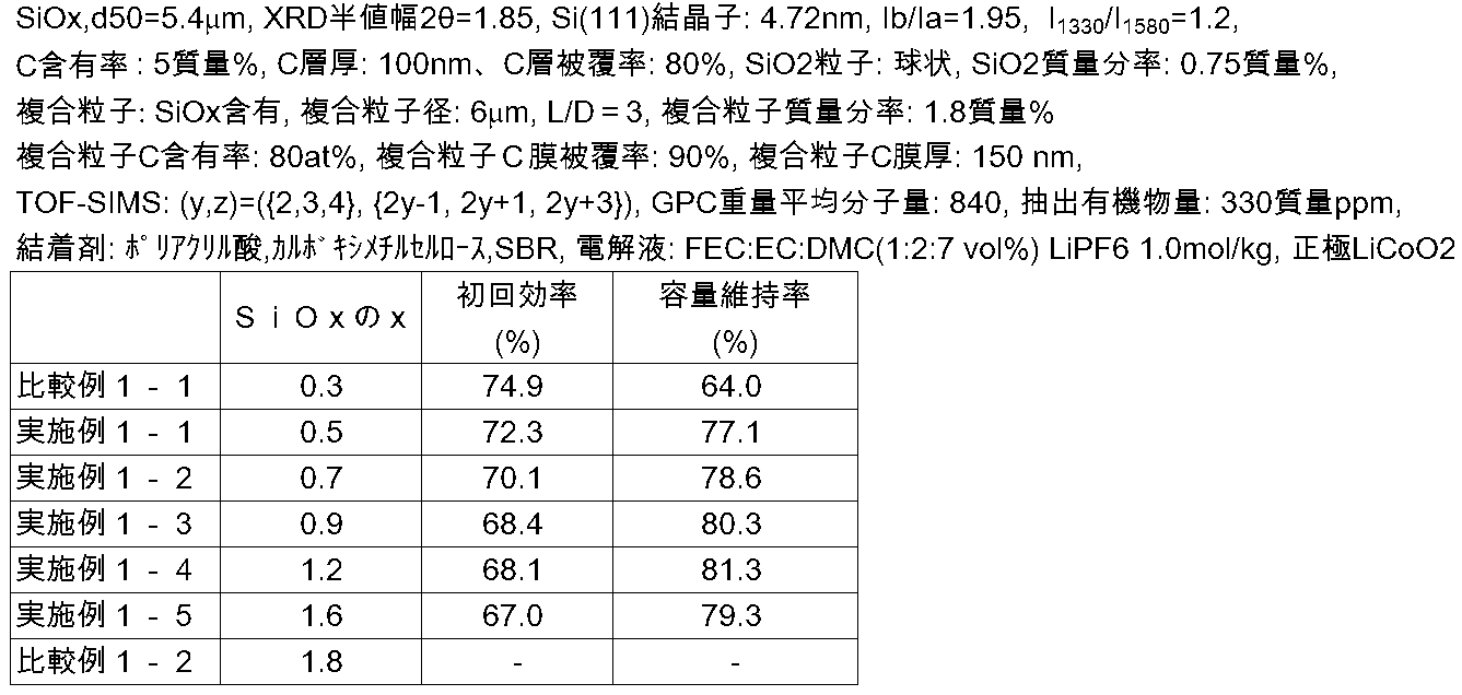
表1に示すように、SiOxで表わされるケイ素化合物において、xの値が、0.5≦x≦1.6の範囲外の場合、電池特性が悪化した。例えば、比較例1-1に示すように、酸素が十分にない場合(x=0.3)初回効率が向上するが、容量維持率が著しく悪化する。一方、比較例1-2に示すように、酸素量が多い場合(x=1.8)導電性の低下が生じ維持率、初回効率とも低下し、測定不可となった。
(実施例2-1~実施例2-4、比較例2-1~比較例2-3)
基本的に実施例1-3と同様に二次電池の製造を行ったが、SiOxで表わされるケイ素化合物において、気化出発材と析出板の位置関係を変えることで、負極活物質粉末中の二酸化ケイ素粒子の質量分率、複合二次粒子の有無、複合二次粒子中のケイ素化合物粒子の有無を表2に示すように変化させた。実施例2-1~実施例2-4、比較例2-1~比較例2-3の二次電池の初回充放電特性及びサイクル特性を調べたところ、表2に示した結果が得られた。
基本的に実施例1-3と同様に二次電池の製造を行ったが、SiOxで表わされるケイ素化合物において、気化出発材と析出板の位置関係を変えることで、負極活物質粉末中の二酸化ケイ素粒子の質量分率、複合二次粒子の有無、複合二次粒子中のケイ素化合物粒子の有無を表2に示すように変化させた。実施例2-1~実施例2-4、比較例2-1~比較例2-3の二次電池の初回充放電特性及びサイクル特性を調べたところ、表2に示した結果が得られた。

表2に示すように、実施例2-1~2-4の複合二次粒子を含むケイ素化合物は、比較例2-1、比較例2-2の複合二次粒子を含まないケイ素化合物に比べて、良好な初回効率及び容量維持率が得られた。また、二酸化ケイ素粒子を2質量%を超えて含む場合、複合二次粒子を含んでいても、初回効率及び容量維持率は悪化した。さらに、複合二次粒子中にケイ素化合物(SiOx)粒子を含む場合は、SiOxを含まない場合に比べて容量維持率の改善が見られた。
(実施例3-1~実施例3-11)
負極活物質粉末に含まれる複合二次粒子の平均粒子径、短径に対する長径の比L/D、及び二酸化ケイ素粒子の形状を変化させたこと以外、実施例1-3と同様に二次電池の製造を行った。負極活物質粉末に含まれる複合二次粒子の平均粒子径及びL/Dは、熱分解CVD時のロータリーキルンの回転数、傾きを調節することで制御した。また、二酸化ケイ素粒子の形状は、気化出発材中の二酸化ケイ素原料の種類を変えることで制御した。実施例3-1~実施例3-11の二次電池のサイクル特性及び初回充放電特性を調べたところ、表3に示した結果が得られた。
負極活物質粉末に含まれる複合二次粒子の平均粒子径、短径に対する長径の比L/D、及び二酸化ケイ素粒子の形状を変化させたこと以外、実施例1-3と同様に二次電池の製造を行った。負極活物質粉末に含まれる複合二次粒子の平均粒子径及びL/Dは、熱分解CVD時のロータリーキルンの回転数、傾きを調節することで制御した。また、二酸化ケイ素粒子の形状は、気化出発材中の二酸化ケイ素原料の種類を変えることで制御した。実施例3-1~実施例3-11の二次電池のサイクル特性及び初回充放電特性を調べたところ、表3に示した結果が得られた。

表3に示すように、負極活物質粉末中の複合二次粒子の平均粒子径、短径に対する長径の比L/D、及び二酸化ケイ素粒子の形状を変えたところ、容量維持率及び初回効率が変化した。複合粒子径が1μm以上15μm以下の範囲にある場合、良好な初回効率及び容量維持率が得られた。また、1≦L/D≦5の範囲にある場合は、L/D>5の場合と比較して良好な容量維持率が得られた。さらに、二酸化ケイ素粒子の形状が球状である場合には、角型である場合と比較して良好な初回効率及び容量維持率が得られた。
(実施例4-1~実施例4-6、比較例4-1)
負極活物質粉末中における複合二次粒子の炭素元素比率、表面被覆率、被覆炭素膜厚、及び負極活物質粉末の総量に対する複合二次粒子の質量分率を表4に示すように変化させた他は、実施例1-3と同様に二次電池の製造を行った。複合二次粒子の炭素元素比率、表面被覆率、被覆炭素膜厚、及び質量分率は、熱分解CVD時のロータリーキルンの炭素源ガス流量、及びキャリアガス流量を調節することで制御した。実施例4-1~実施例4-6.及び比較例4-1の二次電池の初回充放電特性及びサイクル特性を調べたところ、表4に示した結果が得られた。
負極活物質粉末中における複合二次粒子の炭素元素比率、表面被覆率、被覆炭素膜厚、及び負極活物質粉末の総量に対する複合二次粒子の質量分率を表4に示すように変化させた他は、実施例1-3と同様に二次電池の製造を行った。複合二次粒子の炭素元素比率、表面被覆率、被覆炭素膜厚、及び質量分率は、熱分解CVD時のロータリーキルンの炭素源ガス流量、及びキャリアガス流量を調節することで制御した。実施例4-1~実施例4-6.及び比較例4-1の二次電池の初回充放電特性及びサイクル特性を調べたところ、表4に示した結果が得られた。

表4からわかるように、複合二次粒子中に炭素を含まない場合、初回効率及び容量維持率が悪化した。それに対して、複合二次粒子中に炭素を含む場合には良好な初回効率及び容量維持率が見られ、炭素元素比率が60at%以上の時、より良好な電池特性が得られた。また、複合二次粒子の炭素被覆率が30%以上、かつ、炭素膜厚が30nm以上の場合、良好な初回効率及び容量維持率が見られた。さらに、複合二次粒子の質量分率が2質量%以下の範囲にある場合、2質量%以上の場合と比較して良好な結果となった。
(実施例5-1~実施例5-4)
TOF-SIMSにおいてケイ素化合物粒子表面の炭素被膜から検出されるCyHzフラグメントを表5に示すように変化させた他は、実施例1-3と同様に二次電池を作製した。CyHzフラグメント種は、熱分解CVDの際に用いるガス種、CVD温度、及びCVD後処理温度を調整することで制御した。実施例5-1~実施例5-4の二次電池の初回充放電特性及びサイクル特性を調べたところ、表5に示した結果が得られた。
TOF-SIMSにおいてケイ素化合物粒子表面の炭素被膜から検出されるCyHzフラグメントを表5に示すように変化させた他は、実施例1-3と同様に二次電池を作製した。CyHzフラグメント種は、熱分解CVDの際に用いるガス種、CVD温度、及びCVD後処理温度を調整することで制御した。実施例5-1~実施例5-4の二次電池の初回充放電特性及びサイクル特性を調べたところ、表5に示した結果が得られた。

表5からわかるように、y及びzが、6≧y≧2、2y+2≧z≧2y-2という範囲を満たすCyHz系化合物のフラグメントが検出された場合、電池特性が向上した。特に、yの値が小さい場合、すなわち、y=2、3、4のCyHz系化合物のフラグメントのみが検出される場合、電池特性がより向上した。
(実施例6-1~実施例6-11)
ケイ素化合物粒子表面の炭素被膜が含む炭化水素溶媒に可溶な炭素系化合物の重量平均分子量及び含有量を表6に示すように変化させた以外は、実施例1-3と同様に二次電池の製造を行った。このとき、熱分解CVD時のロータリーキルンの炭素源ガスの流量と導入口の位置、キャリアガスの流量と導入口の位置を変えることで、炭素系化合物の重量平均分子量及び含有量を変化させた。実施例6-1~6-11の二次電池の初回充放電特性、及びサイクル特性を調べたところ、表6に示した結果が得られた。
ケイ素化合物粒子表面の炭素被膜が含む炭化水素溶媒に可溶な炭素系化合物の重量平均分子量及び含有量を表6に示すように変化させた以外は、実施例1-3と同様に二次電池の製造を行った。このとき、熱分解CVD時のロータリーキルンの炭素源ガスの流量と導入口の位置、キャリアガスの流量と導入口の位置を変えることで、炭素系化合物の重量平均分子量及び含有量を変化させた。実施例6-1~6-11の二次電池の初回充放電特性、及びサイクル特性を調べたところ、表6に示した結果が得られた。

表6からわかるように、炭素被膜に含まれる炭化水素化合物においてポリスチレン標準で検量線を作成したGPCから得られる重量平均分子量が400以上5000以下の範囲にある場合、良好な初回効率及び充放電効率が得られた。また、この炭素系化合物の含有量が2質量ppm以上6000質量ppm以下の範囲にある場合、電池特性は良好な結果となった。
(実施例7-1~実施例7-4)
ケイ素化合物粒子表面に含まれる炭素質量分率、炭素層厚み、及び炭素層被覆率を表7に示すように変化させた以外は、実施例1-3と同様に二次電池の製造を行った。それぞれの含有量は、熱分解CVDの処理時間を変えることで変化させた。実施例7-1~実施例7-4の二次電池のサイクル特性及び初回充放電特性を調べたところ、表7に示した結果が得られた。
ケイ素化合物粒子表面に含まれる炭素質量分率、炭素層厚み、及び炭素層被覆率を表7に示すように変化させた以外は、実施例1-3と同様に二次電池の製造を行った。それぞれの含有量は、熱分解CVDの処理時間を変えることで変化させた。実施例7-1~実施例7-4の二次電池のサイクル特性及び初回充放電特性を調べたところ、表7に示した結果が得られた。
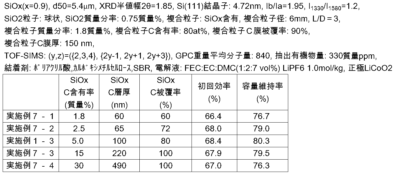
ケイ素化合物粒子表面の炭素被膜の含有率が、2質量%以上20質量%以下の範囲にある場合、初回効率及び容量維持率は、より良い特性となった。ケイ素化合物粒子表面の炭素被膜の含有率が2質量%以上であればケイ素化合物粒子の電子伝導性が良好となる。また、ケイ素化合物粒子表面の炭素被膜の含有率が20質量%以下であればイオン伝導性が良好となる。従って、ケイ素化合物粒子表面の炭素被膜の含有率が上記範囲であれば、容量維持率、初回効率が良好な値となる。
(実施例8-1~実施例8-6)
ケイ素化合物の2θ=21.8°付近のピーク強度に対する28.4°付近のピーク強度の比Ib/Iaを表8に示すように変化させた以外は、実施例1-3と同様に二次電池の製造を行った。ピーク強度比は、熱分解CVD後の非大気雰囲気下の熱処理条件を変えることで変化させた。実施例8-1~8-6の二次電池の初回充放電特性、サイクル特性を調べたところ、表8に示した結果が得られた。
ケイ素化合物の2θ=21.8°付近のピーク強度に対する28.4°付近のピーク強度の比Ib/Iaを表8に示すように変化させた以外は、実施例1-3と同様に二次電池の製造を行った。ピーク強度比は、熱分解CVD後の非大気雰囲気下の熱処理条件を変えることで変化させた。実施例8-1~8-6の二次電池の初回充放電特性、サイクル特性を調べたところ、表8に示した結果が得られた。
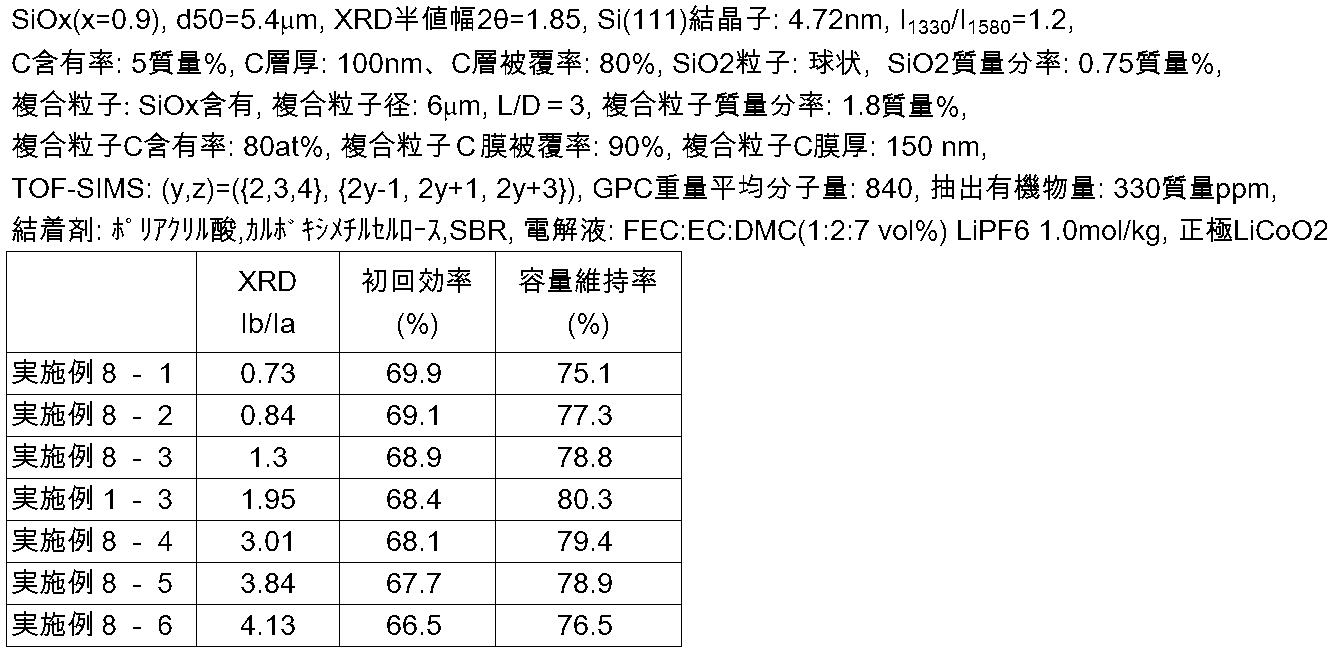
表8からわかるように、0.8≦Ib/Ia≦4.0の範囲にある場合、初回効率、及び容量維持率について良好な値が得られた。これは、負極活物質が適切な強度、安定性と電子伝導性を兼ね備えているためと考えられる。
(実施例9-1~実施例9-8)
ケイ素化合物粒子中のケイ素領域の結晶性を変化させた他は、実施例1-3と同様に二次電池の製造を行った。結晶性の変化は、熱分解CVD後に非大気雰囲気下の熱処理を行うことで制御可能である。実施例9-1~9-8のケイ素系活物質の半値幅を表9に示した。実施例9-8では半値幅を20.221°と算出しているが、解析ソフトを用いフィッティングした結果であり、実質的にピークは得られていない。よって実施例9-8のケイ素系活物質は、実質的に非晶質であると言える。実施例9-1~実施例9-8の二次電池のサイクル特性及び初回充放電特性を調べたところ、表9に示した結果が得られた。
ケイ素化合物粒子中のケイ素領域の結晶性を変化させた他は、実施例1-3と同様に二次電池の製造を行った。結晶性の変化は、熱分解CVD後に非大気雰囲気下の熱処理を行うことで制御可能である。実施例9-1~9-8のケイ素系活物質の半値幅を表9に示した。実施例9-8では半値幅を20.221°と算出しているが、解析ソフトを用いフィッティングした結果であり、実質的にピークは得られていない。よって実施例9-8のケイ素系活物質は、実質的に非晶質であると言える。実施例9-1~実施例9-8の二次電池のサイクル特性及び初回充放電特性を調べたところ、表9に示した結果が得られた。

表9からわかるように、ケイ素化合物の結晶性を変化させたところ、それらの結晶性に応じて容量維持率及び初回効率が変化した。特にSi(111)面に起因する結晶子サイズ7.5nm以下の低結晶性材料で高い容量維持率となる。特に非結晶領域では最も良い容量維持率が得られる。
(実施例10-1~実施例10-6)
表10に示すようにケイ素化合物粒子のメディアン径を表10に示すように調節した以外は、実施例1-3と同様に二次電池を製造した。メディアン径の調節はケイ素化合物粒子の製造工程における粉砕時間、分級条件を変化させることによって行った。実施例10-1~10-6の二次電池の初回充放電特性、サイクル特性を調べたところ、表10に示した結果が得られた。
表10に示すようにケイ素化合物粒子のメディアン径を表10に示すように調節した以外は、実施例1-3と同様に二次電池を製造した。メディアン径の調節はケイ素化合物粒子の製造工程における粉砕時間、分級条件を変化させることによって行った。実施例10-1~10-6の二次電池の初回充放電特性、サイクル特性を調べたところ、表10に示した結果が得られた。
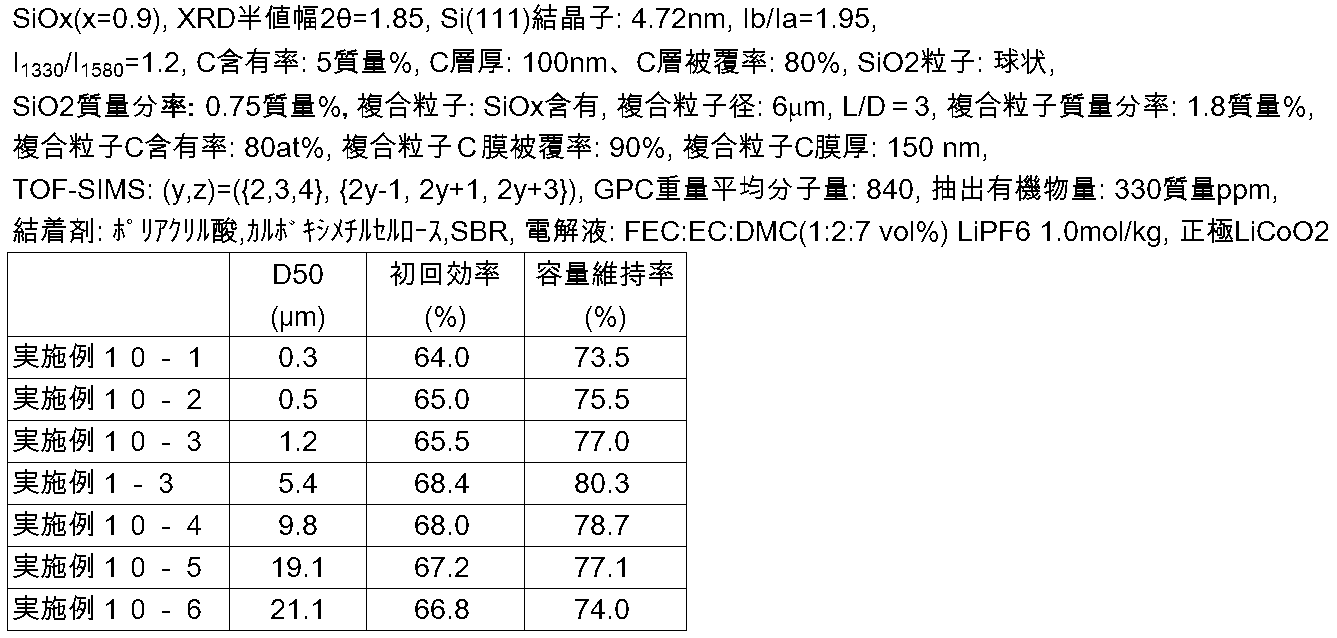
表10からわかるように、ケイ素化合物粒子のメディアン径を変化させたところ、それに応じて維持率および初回効率が変化した。実施例10-2~10-5、実施例1-3に示すように、ケイ素化合物粒子のメディアン径が0.5μm~20μmの範囲内であると容量維持率及び初回効率がより高くなった。特に、メディアン径が4μm~10μmである場合(実施例1-3、実施例10-4)、容量維持率の大きな向上がみられた。
(実施例11-1~11-5)
実施例11-1~実施例11-5では、基本的に実施例1-3と同様に二次電池の製造を行ったが、負極活物質として、さらに、炭素系活物質(黒鉛)を加えた。ここでは、負極中の炭素系活物質材の含有量とケイ素化合物粒子の含有量との比を90:10(質量比)に固定した。すなわち、炭素系活物質とケイ素化合物粒子の総量に対する、ケイ素化合物粒子の割合を10質量%とした。また、熱分解CVD時の温度およびガス圧力を変えることで、ケイ素化合物粒子の表面の炭素被膜の状態を変化させ、ラマンスペクトル分析における、1330cm-1と1580cm-1の散乱ピークの強度比I1330/I1580を表11に示すように変化させた。実施例11-1~11-5の二次電池のサイクル特性、初回充放電特性を調べたところ、表11に示した結果が得られた。
実施例11-1~実施例11-5では、基本的に実施例1-3と同様に二次電池の製造を行ったが、負極活物質として、さらに、炭素系活物質(黒鉛)を加えた。ここでは、負極中の炭素系活物質材の含有量とケイ素化合物粒子の含有量との比を90:10(質量比)に固定した。すなわち、炭素系活物質とケイ素化合物粒子の総量に対する、ケイ素化合物粒子の割合を10質量%とした。また、熱分解CVD時の温度およびガス圧力を変えることで、ケイ素化合物粒子の表面の炭素被膜の状態を変化させ、ラマンスペクトル分析における、1330cm-1と1580cm-1の散乱ピークの強度比I1330/I1580を表11に示すように変化させた。実施例11-1~11-5の二次電池のサイクル特性、初回充放電特性を調べたところ、表11に示した結果が得られた。
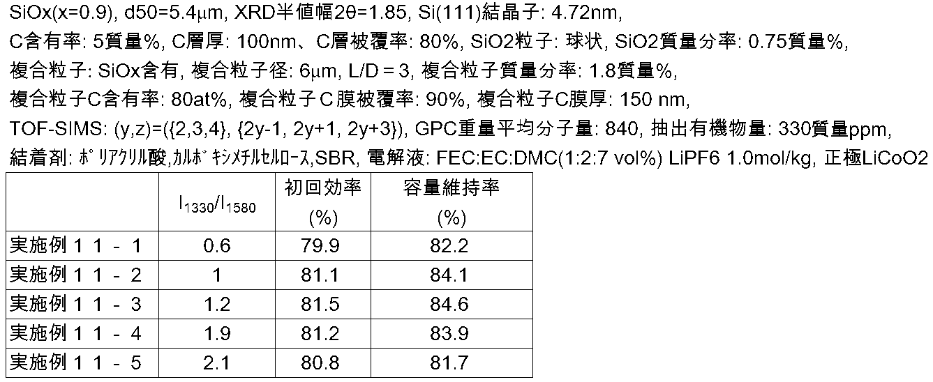
表11に示すように、ラマンスペクトル分析におけるI1330/I1580が2.0を下回る場合は、表面にI1330に由来する乱雑な結合様式をもつ炭素成分が多くなり過ぎず、電子伝導性が良好となるため、維持率、初回効率を向上できる。また、I1330/I1580の値が0.7より大きい場合は、表面におけるI1580に由来する黒鉛等の炭素成分が多くなり過ぎず、イオン電導性及び炭素被膜のケイ素化合物へのLi挿入に伴う膨張への追随性が向上し、容量維持率を向上できる。
なお、本発明は、上記実施形態に限定されるものではない。上記実施形態は、例示であり、本発明の特許請求の範囲に記載された技術的思想と実質的に同一な構成を有し、同様な作用効果を奏するものは、いかなるものであっても本発明の技術的範囲に包含される。
Claims (20)
- 負極活物質粒子を含む非水電解質二次電池用負極活物質であって、
前記負極活物質粒子は、表面の少なくとも一部に炭素被膜を形成したケイ素化合物(SiOx:0.5≦x≦1.6)を含むケイ素化合物粒子を含有し、
該負極活物質は、二酸化ケイ素粒子を2質量%以下含有しており、かつ、複数の該二酸化ケイ素粒子と炭素を含む二酸化ケイ素-炭素複合二次粒子を含むことを特徴とする非水電解質二次電池用負極活物質。 - 前記複合二次粒子が前記ケイ素化合物粒子を含むことを特徴とする請求項1に記載の非水電解質二次電池用負極活物質。
- 前記複合二次粒子の平均粒径が1μm以上15μm以下であることを特徴とする請求項1又は請求項2に記載の非水電解質二次電池用負極活物質。
- 前記複合二次粒子の長径Lと短径Dが、1≦L/D≦5という関係を満たすことを特徴とする請求項1から請求項3のいずれか一項に記載の非水電解質二次電池用負極活物質。
- 前記複合二次粒子を構成する二酸化ケイ素粒子の少なくとも一部は実質的に球状であることを特徴とする請求項1から請求項4のいずれか一項に記載の非水電解質二次電池用負極活物質。
- 前記複合二次粒子の全体に対する炭素の割合が60at%以上であることを特徴とする請求項1から請求項5のいずれか一項に記載の非水電解質二次電池用負極活物質。
- 前記複合二次粒子の表面における炭素の被覆率が30%以上であり、かつ平均の膜厚が30nm以上であることを特徴とする請求項1から請求項6のいずれか一項に記載の非水電解質二次電池用負極活物質。
- 前記複合二次粒子は、負極活物質の総質量に対して2質量%以下であることを特徴とする請求項6または請求項7に記載の非水電解質二次電池用負極活物質。
- 前記ケイ素化合物粒子表面に形成された炭素被膜が、ラマンスペクトル分析において、1330cm-1と1580cm-1に散乱ピークを有し、それらの強度比I1330/I1580が0.7<I1330/I1580<2.0という関係を満たすことを特徴とする請求項1から請求項8のいずれか一項に記載の非水電解質二次電池用負極活物質。
- 前記炭素被膜は、TOF-SIMSによって、CyHz系化合物のフラグメントが検出され、
該CyHz系化合物のフラグメントとして、y及びzが、6≧y≧2、2y+2≧z≧2y-2という範囲を満たすものが、前記炭素被膜の少なくとも一部に検出されることを特徴とする請求項1から請求項9のいずれか一項に記載の非水電解質二次電池用負極活物質。 - 前記炭素被膜が、ポリスチレン標準によるゲルパーミエーションクロマトグラフィにて測定した重量平均分子量が400以上5000以下であり、かつ、炭化水素溶媒に可溶な炭素系化合物を含み、かつ、該炭素系化合物の含有量が、前記ケイ素化合物粒子の全質量に対して2質量ppm以上6000質量ppm以下であることを特徴とする請求項1から請求項10のいずれか一項に記載の非水電解質二次電池用負極活物質。
- 前記炭素被膜の含有率が、前記ケイ素化合物粒子及び前記炭素被膜の合計質量に対し2質量%以上20質量%以下であることを特徴とする請求項1から請求項11のいずれか一項に記載の非水電解質二次電池用負極活物質。
- X線回折スペクトルにおいて、2θ=21.8°付近のピークの強度(Ia)と2θ=28.4°付近のピークの強度(Ib)の関係が、0.8≦Ib/Ia≦4.0であることを特徴とする請求項1から請求項12のいずれか1項に記載の非水電解質二次電池用負極活物質。
- 前記ケイ素化合物粒子が、X線回折により得られるケイ素(111)結晶面に起因する回折ピークの半値幅(2θ)が1.2°以上であると共に、その結晶面に対応する結晶子サイズが7.5nm以下であることを特徴とする請求項1から請求項13のいずれか1項に記載の非水電解質二次電池用負極活物質。
- 前記ケイ素化合物粒子のメディアン径は0.5μm以上20μm以下であることを特徴とする請求項1から請求項14のいずれか1項に記載の非水電解質二次電池用負極活物質。
- 請求項1から請求項15のいずれか1項に記載の非水電解質二次電池用負極活物質と、炭素系活物質とを含むことを特徴とする非水電解質二次電池用負極。
- 前記炭素系活物質と前記ケイ素化合物粒子の総質量に対する、前記ケイ素化合物粒子の割合が4質量%以上のものであることを特徴とする請求項16に記載の非水電解質二次電池用負極。
- 請求項16又は請求項17に記載の非水電解質二次電池用負極を用いたものであることを特徴とする非水電解質二次電池。
- 負極活物質粒子を有する非水電解質二次電池用負極活物質の製造方法であって、
一般式SiOx(0.5≦x≦1.6)で表されるケイ素化合物を含むケイ素化合物粒子を作製する工程と、
前記ケイ素化合物粒子の表面の少なくとも一部を炭素被膜で被覆する工程と、
複数の二酸化ケイ素粒子及び炭素を含む二酸化ケイ素-炭素複合二次粒子を形成する工程と
により負極活物質を製造し、
該製造した負極活物質から、二酸化ケイ素粒子を2質量%以下含有しており、かつ、前記二酸化ケイ素-炭素複合二次粒子を含むものを選別する工程を有することを特徴とする非水電解質二次電池用負極活物質の製造方法。 - 前記ケイ素化合物粒子の表面の少なくとも一部を炭素被膜で被覆する工程、及び、前記二酸化ケイ素‐炭素複合二次粒子を形成する工程が連続炉により行われ、
該連続炉が、炉芯管が回転することにより内部の前記負極活物質を混合・攪拌しながら、炭素源ガスを加熱・分解するロータリーキルンであることを特徴とする請求項19に記載の非水電解質二次電池用負極活物質の製造方法。
Priority Applications (3)
| Application Number | Priority Date | Filing Date | Title |
|---|---|---|---|
| KR1020187018575A KR20180093005A (ko) | 2016-01-04 | 2016-12-16 | 비수 전해질 2차 전지용 부극 활물질, 비수 전해질 2차 전지용 부극 및 비수 전해질 2차 전지, 및 비수 전해질 2차 전지용 부극 활물질의 제조 방법 |
| CN201680077807.2A CN108475781B (zh) | 2016-01-04 | 2016-12-16 | 非水电解质二次电池用负极活性物质及其制造方法、非水电解质二次电池用负极及二次电池 |
| US16/063,016 US10559812B2 (en) | 2016-01-04 | 2016-12-16 | Negative electrode active material for nonaqueous electrolyte secondary battery, negative electrode for nonaqueous electrolyte secondary battery, nonaqueous electrolyte secondary battery, and production method of negative electrode active material for nonaqueous electrolyte secondary battery |
Applications Claiming Priority (2)
| Application Number | Priority Date | Filing Date | Title |
|---|---|---|---|
| JP2016-000287 | 2016-01-04 | ||
| JP2016000287A JP6433442B2 (ja) | 2016-01-04 | 2016-01-04 | 非水電解質二次電池用負極活物質、非水電解質二次電池用負極、及び非水電解質二次電池、並びに非水電解質二次電池用負極活物質の製造方法 |
Publications (1)
| Publication Number | Publication Date |
|---|---|
| WO2017119032A1 true WO2017119032A1 (ja) | 2017-07-13 |
Family
ID=59273444
Family Applications (1)
| Application Number | Title | Priority Date | Filing Date |
|---|---|---|---|
| PCT/JP2016/005149 Ceased WO2017119032A1 (ja) | 2016-01-04 | 2016-12-16 | 非水電解質二次電池用負極活物質、非水電解質二次電池用負極、及び非水電解質二次電池、並びに非水電解質二次電池用負極活物質の製造方法 |
Country Status (5)
| Country | Link |
|---|---|
| US (1) | US10559812B2 (ja) |
| JP (1) | JP6433442B2 (ja) |
| KR (1) | KR20180093005A (ja) |
| CN (1) | CN108475781B (ja) |
| WO (1) | WO2017119032A1 (ja) |
Cited By (2)
| Publication number | Priority date | Publication date | Assignee | Title |
|---|---|---|---|---|
| US20220029151A1 (en) * | 2018-12-21 | 2022-01-27 | Panasonic Intellectual Property Management Co., Ltd. | Negative electrode active material for secondary batteries, and secondary battery |
| JPWO2022254872A1 (ja) * | 2021-05-31 | 2022-12-08 |
Families Citing this family (11)
| Publication number | Priority date | Publication date | Assignee | Title |
|---|---|---|---|---|
| US12148917B2 (en) * | 2019-03-28 | 2024-11-19 | Panasonic Intellectual Property Management Co., Ltd. | Nonaqueous electrolyte secondary battery negative electrode and nonaqueous electrolyte secondary battery |
| CN111162268B (zh) * | 2019-09-26 | 2021-06-18 | 贝特瑞新材料集团股份有限公司 | 一种复合负极材料及其制备方法和锂离子电池 |
| WO2021189349A1 (zh) * | 2020-03-26 | 2021-09-30 | 宁德新能源科技有限公司 | 负极材料、负极极片、包含该负极极片的电化学装置及电子装置 |
| CN115552676A (zh) | 2020-03-30 | 2022-12-30 | 松下知识产权经营株式会社 | 二次电池 |
| JP7692684B2 (ja) * | 2020-06-11 | 2025-06-16 | 株式会社Aescジャパン | 負極電極、リチウムイオン二次電池、リチウムイオン二次電池用負極電極の製造方法、および、リチウムイオン二次電池用負極電極シートの製造方法 |
| JP7697007B2 (ja) | 2020-11-30 | 2025-06-23 | ワッカー ケミー アクチエンゲゼルシャフト | ケイ素含有材料 |
| CN116745459A (zh) | 2020-11-30 | 2023-09-12 | 瓦克化学股份公司 | 制造含硅材料的方法 |
| KR20240038083A (ko) | 2021-07-29 | 2024-03-22 | 와커 헤미 아게 | 캐스케이드 반응기 시스템에서 규소 함유 물질을 제조하는 방법 |
| JP7799059B2 (ja) | 2021-12-02 | 2026-01-14 | ワッカー ケミー アクチエンゲゼルシャフト | ケイ素含有材料を製造する方法 |
| US12570533B2 (en) | 2021-12-20 | 2026-03-10 | Wacker Chemie Ag | Process for producing silicon-containing materials in a stirred-tank reactor |
| CN116093331B (zh) * | 2023-04-06 | 2023-06-23 | 宁德新能源科技有限公司 | 二次电池和电子装置 |
Citations (2)
| Publication number | Priority date | Publication date | Assignee | Title |
|---|---|---|---|---|
| JP2004063433A (ja) * | 2001-12-26 | 2004-02-26 | Shin Etsu Chem Co Ltd | 導電性酸化珪素粉末、その製造方法及び該粉末を用いた非水電解質二次電池用負極材 |
| WO2015198511A1 (ja) * | 2014-06-23 | 2015-12-30 | 信越化学工業株式会社 | 非水電解質二次電池用負極材、非水電解質二次電池用負極及び非水電解質二次電池並びに負極活物質粒子の製造方法 |
Family Cites Families (16)
| Publication number | Priority date | Publication date | Assignee | Title |
|---|---|---|---|---|
| JP2997741B2 (ja) | 1992-07-29 | 2000-01-11 | セイコーインスツルメンツ株式会社 | 非水電解質二次電池及びその製造方法 |
| JP2001185127A (ja) | 1999-12-24 | 2001-07-06 | Fdk Corp | リチウム2次電池 |
| JP3865033B2 (ja) | 2000-02-04 | 2007-01-10 | 信越化学工業株式会社 | 酸化珪素粉末の連続製造方法及び連続製造装置 |
| JP2002042806A (ja) | 2000-07-19 | 2002-02-08 | Japan Storage Battery Co Ltd | 非水電解質二次電池 |
| JP4519592B2 (ja) * | 2004-09-24 | 2010-08-04 | 株式会社東芝 | 非水電解質二次電池用負極活物質及び非水電解質二次電池 |
| JP4367311B2 (ja) | 2004-10-18 | 2009-11-18 | ソニー株式会社 | 電池 |
| JP4994634B2 (ja) | 2004-11-11 | 2012-08-08 | パナソニック株式会社 | リチウムイオン二次電池用負極、その製造方法、およびそれを用いたリチウムイオン二次電池 |
| JP4911990B2 (ja) | 2006-02-27 | 2012-04-04 | 三洋電機株式会社 | リチウム二次電池用負極及びその製造方法並びにリチウム二次電池 |
| JP2008177346A (ja) | 2007-01-18 | 2008-07-31 | Sanyo Electric Co Ltd | エネルギー貯蔵デバイス |
| JP5108355B2 (ja) | 2007-03-30 | 2012-12-26 | パナソニック株式会社 | リチウム二次電池用負極およびそれを備えたリチウム二次電池、ならびにリチウム二次電池用負極の製造方法 |
| KR100913177B1 (ko) | 2007-09-17 | 2009-08-19 | 삼성에스디아이 주식회사 | 리튬 이차 전지용 음극 활물질 및 이의 제조 방법 |
| JP5196149B2 (ja) | 2008-02-07 | 2013-05-15 | 信越化学工業株式会社 | 非水電解質二次電池用負極材及びその製造方法並びにリチウムイオン二次電池及び電気化学キャパシタ |
| JP5555978B2 (ja) | 2008-02-28 | 2014-07-23 | 信越化学工業株式会社 | 非水電解質二次電池用負極活物質、及びそれを用いた非水電解質二次電池 |
| JP5329858B2 (ja) | 2008-07-10 | 2013-10-30 | 株式会社東芝 | 非水電解質二次電池用負極活物質の製造方法およびこれによって得られる非水電解質電池用負極活物質 |
| US20110135810A1 (en) | 2009-12-03 | 2011-06-09 | Marina Yakovleva | Finely deposited lithium metal powder |
| JP6082355B2 (ja) * | 2014-02-07 | 2017-02-15 | 信越化学工業株式会社 | 非水電解質二次電池の負極材用の負極活物質、及び非水電解質二次電池用負極電極、並びに非水電解質二次電池 |
-
2016
- 2016-01-04 JP JP2016000287A patent/JP6433442B2/ja active Active
- 2016-12-16 KR KR1020187018575A patent/KR20180093005A/ko not_active Withdrawn
- 2016-12-16 WO PCT/JP2016/005149 patent/WO2017119032A1/ja not_active Ceased
- 2016-12-16 CN CN201680077807.2A patent/CN108475781B/zh active Active
- 2016-12-16 US US16/063,016 patent/US10559812B2/en active Active
Patent Citations (2)
| Publication number | Priority date | Publication date | Assignee | Title |
|---|---|---|---|---|
| JP2004063433A (ja) * | 2001-12-26 | 2004-02-26 | Shin Etsu Chem Co Ltd | 導電性酸化珪素粉末、その製造方法及び該粉末を用いた非水電解質二次電池用負極材 |
| WO2015198511A1 (ja) * | 2014-06-23 | 2015-12-30 | 信越化学工業株式会社 | 非水電解質二次電池用負極材、非水電解質二次電池用負極及び非水電解質二次電池並びに負極活物質粒子の製造方法 |
Cited By (5)
| Publication number | Priority date | Publication date | Assignee | Title |
|---|---|---|---|---|
| US20220029151A1 (en) * | 2018-12-21 | 2022-01-27 | Panasonic Intellectual Property Management Co., Ltd. | Negative electrode active material for secondary batteries, and secondary battery |
| US12095076B2 (en) * | 2018-12-21 | 2024-09-17 | Panasonic Intellectual Property Management Co., Ltd. | Negative electrode active material for secondary batteries, and secondary battery |
| JPWO2022254872A1 (ja) * | 2021-05-31 | 2022-12-08 | ||
| WO2022254872A1 (ja) * | 2021-05-31 | 2022-12-08 | パナソニックIpマネジメント株式会社 | 被覆活物質、電極材料および電池 |
| JP7788681B2 (ja) | 2021-05-31 | 2025-12-19 | パナソニックIpマネジメント株式会社 | 被覆活物質、電極材料および電池 |
Also Published As
| Publication number | Publication date |
|---|---|
| CN108475781A (zh) | 2018-08-31 |
| JP2017123220A (ja) | 2017-07-13 |
| US10559812B2 (en) | 2020-02-11 |
| KR20180093005A (ko) | 2018-08-20 |
| JP6433442B2 (ja) | 2018-12-05 |
| CN108475781B (zh) | 2021-05-07 |
| US20190006656A1 (en) | 2019-01-03 |
Similar Documents
| Publication | Publication Date | Title |
|---|---|---|
| JP6433442B2 (ja) | 非水電解質二次電池用負極活物質、非水電解質二次電池用負極、及び非水電解質二次電池、並びに非水電解質二次電池用負極活物質の製造方法 | |
| JP6457590B2 (ja) | 負極活物質、負極活物質材料、負極電極、リチウムイオン二次電池、負極電極の製造方法、負極活物質の製造方法、並びに、リチウムイオン二次電池の製造方法 | |
| JP6359836B2 (ja) | 非水電解質二次電池用負極材、非水電解質二次電池用負極及びその製造方法並びに非水電解質二次電池 | |
| CN107636868B (zh) | 二次电池、负极、活性物质、及活性物质颗粒的制造方法 | |
| JP6268049B2 (ja) | 非水電解質二次電池用負極材及び非水電解質二次電池並びに負極活物質粒子の製造方法 | |
| KR102560936B1 (ko) | 비수전해질 이차 전지용 부극 활물질 및 비수전해질 이차 전지, 및 비수전해질 이차 전지용 부극재의 제조 방법 | |
| JP6196192B2 (ja) | 負極活物質、負極活物質の製造方法、並びに、リチウムイオン二次電池 | |
| CN108292748B (zh) | 负极活性物质、锂离子二次电池及其制造方法、混合负极活性物质材料、负极 | |
| JP6312211B2 (ja) | 非水電解質二次電池用負極活物質、非水電解質二次電池用負極、非水電解質二次電池、及び非水電解質二次電池用負極材の製造方法 | |
| CN105932268B (zh) | 非水电解质二次电池、其负极、其负极活性物质、其负极材料的制造方法 | |
| JP6592603B2 (ja) | 負極活物質、混合負極活物質材料、及び負極活物質の製造方法 | |
| JP6196183B2 (ja) | 非水電解質二次電池用負極材及びその製造方法、並びに非水電解質二次電池用負極活物質層、非水電解質二次電池用負極、非水電解質二次電池 | |
| CN108701824B (zh) | 负极活性物质、混合负极活性物质、二次电池用负极、二次电池、及负极活性物质的制造 | |
| JP6564740B2 (ja) | 負極活物質、負極、リチウムイオン二次電池、リチウムイオン二次電池の使用方法、負極活物質の製造方法及びリチウムイオン二次電池の製造方法 | |
| JP2015111547A5 (ja) | ||
| WO2015107581A1 (ja) | 非水電解質二次電池用負極材及び負極活物質粒子の製造方法 | |
| WO2015118830A1 (ja) | 非水電解質二次電池の負極材用の負極活物質、及び非水電解質二次電池用負極電極、並びに非水電解質二次電池 | |
| JP6467031B2 (ja) | 非水電解質二次電池用負極材及び非水電解質二次電池 | |
| WO2017119031A1 (ja) | 負極活物質、混合負極活物質材料、非水電解質二次電池用負極、リチウムイオン二次電池、負極活物質の製造方法、及びリチウムイオン二次電池の製造方法 | |
| JP2016066508A (ja) | 非水電解質二次電池用負極及び非水電解質二次電池 | |
| JP6634398B2 (ja) | 負極活物質、混合負極活物質材料、及び負極活物質の製造方法 | |
| JP2017147058A (ja) | 負極活物質、混合負極活物質材料、非水電解質二次電池用負極、リチウムイオン二次電池、及び負極活物質の製造方法 | |
| JP6496864B2 (ja) | 非水電解質二次電池用負極材の製造方法 |
Legal Events
| Date | Code | Title | Description |
|---|---|---|---|
| 121 | Ep: the epo has been informed by wipo that ep was designated in this application |
Ref document number: 16883538 Country of ref document: EP Kind code of ref document: A1 |
|
| ENP | Entry into the national phase |
Ref document number: 20187018575 Country of ref document: KR Kind code of ref document: A |
|
| NENP | Non-entry into the national phase |
Ref country code: DE |
|
| 122 | Ep: pct application non-entry in european phase |
Ref document number: 16883538 Country of ref document: EP Kind code of ref document: A1 |