WO2017110949A1 - 回転電機およびその製造方法 - Google Patents
回転電機およびその製造方法 Download PDFInfo
- Publication number
- WO2017110949A1 WO2017110949A1 PCT/JP2016/088247 JP2016088247W WO2017110949A1 WO 2017110949 A1 WO2017110949 A1 WO 2017110949A1 JP 2016088247 W JP2016088247 W JP 2016088247W WO 2017110949 A1 WO2017110949 A1 WO 2017110949A1
- Authority
- WO
- WIPO (PCT)
- Prior art keywords
- coil
- phase
- unit
- winding
- pitch
- Prior art date
- Legal status (The legal status is an assumption and is not a legal conclusion. Google has not performed a legal analysis and makes no representation as to the accuracy of the status listed.)
- Ceased
Links
Images



































Classifications
-
- H—ELECTRICITY
- H02—GENERATION; CONVERSION OR DISTRIBUTION OF ELECTRIC POWER
- H02K—DYNAMO-ELECTRIC MACHINES
- H02K3/00—Details of windings
- H02K3/04—Windings characterised by the conductor shape, form or construction, e.g. with bar conductors
-
- H—ELECTRICITY
- H02—GENERATION; CONVERSION OR DISTRIBUTION OF ELECTRIC POWER
- H02K—DYNAMO-ELECTRIC MACHINES
- H02K15/00—Processes or apparatus specially adapted for manufacturing, assembling, maintaining or repairing of dynamo-electric machines
- H02K15/08—Forming windings by laying conductors into or around core parts
- H02K15/085—Forming windings by laying conductors into or around core parts by laying conductors into slotted stators
-
- H—ELECTRICITY
- H02—GENERATION; CONVERSION OR DISTRIBUTION OF ELECTRIC POWER
- H02K—DYNAMO-ELECTRIC MACHINES
- H02K3/00—Details of windings
- H02K3/04—Windings characterised by the conductor shape, form or construction, e.g. with bar conductors
- H02K3/28—Layout of windings or of connections between windings
Definitions
- the present invention relates to a rotary electric machine including a wave coiled stator coil and a method for manufacturing the same.
- FIGS. 3 and 2 of Non-Patent Document 1 show connection diagrams of three-phase armature windings having three slots per phase per pole. Further, FIGS. 3 and 3 of Non-Patent Document 1 show connection diagrams of three-phase armature windings having 2.5 slots per phase per pole. These three-phase armature windings have the same number of coil turns and the same winding pitch, and are wound in two layers.
- stator coil wound by double-layer winding when the stator coil wound by double-layer winding is assembled to the stator core, it is necessary to adjust the assembly order of the coil side inserted through the slot, and the assembly work of the stator coil is complicated. Become. As described above, it is difficult to assemble the stator coil wound in the double layer winding in units of phase coils, and the work efficiency of the assembly work of the stator coil is lowered.
- This invention is made in view of such a situation, and makes it a subject to provide the rotary electric machine provided with the stator coil of the wave winding structure which can be assembled
- a rotating electrical machine includes a stator having a stator core in which a plurality of slots are formed and a stator coil wound around the plurality of slots, and is movably supported with respect to the stator.
- a rotary electric machine comprising: a movable armature core; and a mover comprising at least a pair of mover magnetic poles provided on the mover iron core, wherein the moving direction of the mover relative to the stator is first.
- the stator coil is A plurality of coil sides accommodated in the plurality of slots, the coil sides on one end side in the third direction of the plurality of coil sides, and the coil sides on the other end side in the third direction.
- a plurality of unit coils having a plurality of coil ends that are alternately connected to form a wave winding configuration, and the coil pitch between the coil sides to which the plurality of coil ends are connected is the number of the plurality of slots.
- the unit coil having a full-pitch winding portion set to a single value obtained by dividing the number of slots by the number of magnetic poles of the mover is a full-pitch unit coil, and the coil pitch is compared with the full-pitch winding portion.
- a short-pitch portion set short and a long-pitch portion whose coil pitch is set longer than the full-pitch winding portion are alternately repeated in the first direction, and the short-pitch winding
- the unit coil in which the added value of the adjacent coil pitch obtained by adding the coil pitch of the coil portion and the coil pitch of the long winding portion is set to the value obtained by dividing the number of slots by the number of pole pairs of the mover is shortened.
- the stator coil is at least the short-pitch long-pitch unit coil of the full-pitch unit coil and the short-pitch long-pitch unit coil, and has a configuration of the coil pitch.
- the plurality of unit coils constituting the coil have a plurality of coil sides when the plurality of coil sides of one unit coil are accommodated in the plurality of slots with respect to the occupied state of the plurality of slots.
- the coil side has two types of unit coils including a half coil that occupies half of each of the plurality of slots.
- the stator coil is at least a short-pitch long-pitch unit coil of a full-pitch unit coil and a short-pitch long-pitch unit coil, and has a coil pitch configuration.
- Different types of unit coils are provided.
- the stator coil includes a plurality of phase coils in which a plurality of unit coils each including at least one of a plurality of types of unit coils are electrically connected in series. Further, the plurality of unit coils constituting each phase coil includes two types of unit coils, a full coil and a half coil, with respect to the occupied state of the plurality of slots.
- the rotating electrical machine according to the present invention can form a stator coil with a single-layer wave winding configuration in which the phase coil is wound in one direction in the first direction, and the stator coil is configured in units of phase coils. It is possible to assemble with. Therefore, the rotating electrical machine according to the present invention improves the working efficiency of the stator coil assembling work, as compared with the rotating electrical machine including the stator coil wound with the double layer winding.
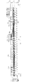
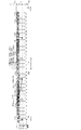
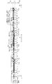
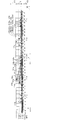
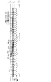
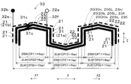
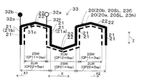
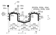
- FIG. 4 is a cut end view showing a part of an end face obtained by cutting the rotary electric machine 100 on a plane perpendicular to a third direction (arrow Z direction) according to the first embodiment. It is a figure which shows typically the structural example of the phase coil 33 concerning the first embodiment seen from the slot opening part 11b side of the 2nd direction (arrow Y direction).
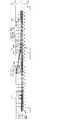
- FIG. 4 is a diagram schematically illustrating a configuration example of a U-phase coil 33u according to the first embodiment.
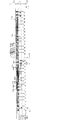
- FIG. 4 is a diagram schematically illustrating a configuration example of a three-phase phase coil 33 (a U-phase coil 33u, a V-phase coil 33v, and a W-phase coil 33w) according to the first embodiment.
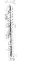
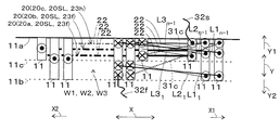
- FIG. 5A viewed from the pair of coil lead-out portions 32f and 32s in the third direction (arrow Z direction) according to the first embodiment is schematically shown.
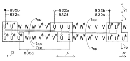
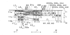
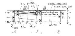
- FIG. 2 the phase coil 33 shown in FIG. 2 viewed from the pair of coil lead-out portions 32f and 32s in the third direction (arrow Z direction) is mounted in a plurality (nine) of the slots 11. It is a figure which shows a state typically.
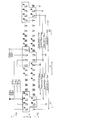
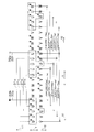
- connection of three-phase phase coils 33 (U-phase coil 33u, V-phase coil 33v, and W-phase coil 33w) viewed from the slot opening 11b side in the second direction (arrow Y direction) according to the first embodiment. It is a connection diagram which shows an example. According to the first embodiment, the three-phase coil 33 (U-phase coil 33u, V-phase coil 33v) shown in FIG. 7A viewed from the pair of coil lead-out portions 32f and 32s in the third direction (arrow Z direction). And a W-phase coil 33w) is a view schematically showing a state in which the plurality of slots 11 are mounted.
- one phase coil 33 of the three-phase coils 33 (U-phase coil 33u, V-phase coil 33v, and W-phase coil 33w) after the annular coil is deformed unevenly is schematically illustrated.
- FIG. 8A schematically shows a state where the inserter blade 3B is inserted into the stator core 10 in a state where the phase coil 33 shown in FIG. 8A is dropped into the support portion 3B1 of the inserter blade 3B according to the first embodiment. It is a schematic diagram shown.
- one phase coil 33 of the three-phase phase coils 33 (U-phase coil 33u, V-phase coil 33v and W-phase coil 33w) is inserted into the plurality of slots 11 by the coil insertion machine 3I.
- the phase coils 33 shown in FIG. 9 viewed from the pair of coil lead-out portions 32f and 32s in the third direction (arrow Z direction) are mounted in a plurality (nine) of the slots 11. It is a figure which shows a state typically.
- phase coil 33 shown in FIG. 11 viewed from the pair of coil lead-out portions 32f and 32s in the third direction (arrow Z direction) is mounted in a plurality (nine) of the slots 11. It is a figure which shows a state typically. It is a figure which shows typically the example of a structure of the phase coil 33 concerning the 3rd deformation form seen from the slot opening part 11b side of the 2nd direction (arrow Y direction).
- phase coils 33 shown in FIG. 15 viewed from the pair of coil lead-out portions 32f and 32s in the third direction (arrow Z direction) are mounted in a plurality (six) of the slots 11. It is a figure which shows a state typically.
- phase coils 33 shown in FIG. 17 viewed from the pair of coil lead-out portions 32 f and 32 s in the third direction (arrow Z direction) are mounted in a plurality (six) of the slots 11. It is a figure which shows a state typically. It is a figure which shows typically the structural example of the phase coil 33 concerning the 6th deformation
- phase coils 33 shown in FIG. 21 viewed from the pair of coil lead-out portions 32f and 32s in the third direction (arrow Z direction) are mounted in a plurality (six) of slots 11. It is a figure which shows a state typically. It is a figure which shows typically the example of a structure of the phase coil 33 concerning the 7th deformation form seen from the slot opening part 11b side of the 2nd direction (arrow Y direction). According to the seventh modification, phase coils 33 shown in FIG. 21 viewed from the pair of coil lead-out portions 32f and 32s in the third direction (arrow Z direction) are mounted in a plurality (six) of slots 11. It is a figure which shows a state typically.
- a three-phase coil 33 (U-phase coil 33u, V-phase coil 33v, and W-phase coil) viewed from the pair of coil lead-out portions 32f and 32s in the third direction (arrow Z direction).
- 33 w) is a diagram schematically showing a state in which each half coil 23 h of 33 w is mounted in a plurality of slots 11.
- FIG. 6 is a diagram schematically illustrating angles ⁇ a1 and ⁇ a2 formed by a first vector 35a and second vectors 35b and 35b according to the first embodiment.
- a three-phase coil 33 (U-phase coil 33u, V-phase coil 33v, and W-phase coil) viewed from the pair of coil lead-out portions 32f and 32s in the third direction (arrow Z direction) 33 w) is a diagram schematically showing a state in which each half coil 23 h of 33 w is mounted in a plurality of slots 11.
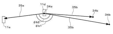
- FIG. 20 is a diagram schematically showing angles ⁇ b1 and ⁇ b2 formed by a first vector 35a and second vectors 35b and 35b according to an eighth modification.
- FIG. 4 is a diagram illustrating an example of a phase arrangement of a plurality of slots 11 according to the first embodiment.
- connection of three-phase coils 33 (U-phase coil 33u, V-phase coil 33v, and W-phase coil 33w) viewed from the slot opening 11b side in the second direction (arrow Y direction).
- U-phase coil 33u seen from a pair of coil extraction part 32f, 32s side in 3rd direction (arrow Z direction) was mounted
- V phase coil 33v seen from the pair of coil extraction parts 32f and 32s side of 3rd direction (arrow Z direction) was mounted
- a three-phase phase coil 33 (a U-phase coil 33u, a V-phase coil 33v, and a W-phase coil) viewed from the pair of coil lead-out portions 32f and 32s in the third direction (arrow Z direction) 33 w) is a diagram schematically showing a state in which each half coil 23 h of 33 w is mounted in a plurality of slots 11.
- a three-phase coil 33 (a U-phase coil 33u, a V-phase coil 33v, and a W-phase coil) viewed from the pair of coil lead portions 32f and 32s in the third direction (arrow Z direction) 33 w) is a diagram schematically showing a state in which each half coil 23 h of 33 w is mounted in a plurality of slots 11. It is a figure which concerns on a 9th modification and shows an example of the phase arrangement
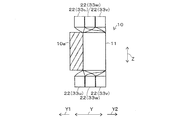
- the stator 40 is cut along the second direction (arrow Y direction), and each unit coil for each phase coil 33 (U-phase coil 33u, V-phase coil 33v, and W-phase coil 33w). It is a cutting part end elevation showing typically an example of the state where 20 pairs of coil ends 22 and 22 are arranged. According to the first embodiment, the stator 40 is cut along the second direction (arrow Y direction), and each unit coil for each phase coil 33 (U-phase coil 33u, V-phase coil 33v, and W-phase coil 33w).
- FIG. 33A It is a cutting part end view showing typically another example of the state where 20 pairs of coil ends 22 and 22 are arranged.
- FIG. 33A shows an example of the connection of the U-phase coil 33u which concerns on 2nd embodiment and was seen from the slot opening part 11b side of the 2nd direction (arrow Y direction).
- 33 schematically shows a state in which the U-phase coils 33u shown in FIG. 33A viewed from the pair of coil lead-out portions 32f and 32s in the third direction (arrow Z direction) are mounted in the plurality of slots 11 according to the second embodiment.
- FIG. 33A shows an example of the connection of the U-phase coil 33u which concerns on 2nd embodiment and was seen from the slot opening part 11b side of the 2nd direction (arrow Y direction).
- 33 schematically shows a state in which the U-phase coils 33u shown in FIG. 33A viewed from the pair of coil lead-out portions 32f and 32s in the third direction (arrow Z direction) are mounted in the plurality of slots 11 according to
- connection of three-phase phase coils 33 (U-phase coil 33u, V-phase coil 33v, and W-phase coil 33w) viewed from the slot opening 11b side in the second direction (arrow Y direction). It is a connection diagram which shows an example.
- the three-phase coil 33 (U-phase coil 33u, V-phase coil 33v) shown in FIG. 34A viewed from the pair of coil lead-out portions 32f and 32s in the third direction (arrow Z direction).
- a W-phase coil 33w) is a view schematically showing a state in which the plurality of slots 11 are mounted.
- FIG. 35 shows typically the structural example of the phase coil 33 concerning the 11th deformation form seen from the slot opening part 11b side of the 2nd direction (arrow Y direction).
- the phase coils 33 shown in FIG. 35 viewed from the pair of coil lead-out portions 32f and 32s in the third direction (arrow Z direction) are mounted in a plurality (nine) of the slots 11.
- a three-phase coil 33 (U-phase coil 33u, V-phase coil 33v, and W-phase coil) viewed from the pair of coil lead-out portions 32f and 32s in the third direction (arrow Z direction).
- 33 w is a diagram schematically showing a state in which each half coil 23 h of 33 w is mounted in a plurality of slots 11.
- a state in which the U-phase coil 33u viewed from the pair of coil lead portions 32f and 32s in the third direction (arrow Z direction) is mounted in the plurality of slots 11 according to the twelfth modification is schematically shown.
- FIG. A state in which the V-phase coil 33v viewed from the pair of coil lead portions 32f and 32s in the third direction (arrow Z direction) is mounted in the plurality of slots 11 according to the twelfth modification is schematically shown.
- FIG. 1 A state in which the W-phase coil 33w viewed from the pair of coil lead portions 32f and 32s in the third direction (arrow Z direction) is mounted in the plurality of slots 11 according to the twelfth modification is schematically shown.
- FIG. According to the twelfth modification a three-phase coil 33 (U-phase coil 33u, V-phase coil 33v, and W-phase) viewed from the pair of coil lead-out portions 32f and 32s in the third direction (arrow Z direction). It is a figure which shows typically the state by which each half coil 23h of the coil 33w was mounted
- FIG. FIG. 6 is a diagram illustrating an example of a phase arrangement of a plurality of slots 11 according to the second embodiment.
- one layer on the second direction slot opening side (arrow Y2 direction) is divided into two slots pitch (2sp) on the first direction wave winding forward side (arrow X2 direction). It is a figure which shows the state moved minutely. It is a figure which shows typically the structural example of the phase coil 33 concerning the 15th deformation form seen from the slot opening part 11b side of the 2nd direction (arrow Y direction). According to the fifteenth modification, the phase coils 33 shown in FIG. 49 viewed from the pair of coil lead-out portions 32f and 32s in the third direction (arrow Z direction) are mounted in a plurality (nine) of the slots 11.
- FIG. 49 viewed from the pair of coil lead-out portions 32f and 32s in the third direction (arrow Z direction) are mounted in a plurality (nine) of the slots 11.
- phase coils 33 shown in FIG. 51 viewed from the pair of coil lead-out portions 32f and 32s in the third direction (arrow Z direction) are mounted in a plurality (nine) of slots 11.
- FIG. It is a figure which shows typically the structural example of the phase coil 33 concerning the 17th deformation
- phase coils 33 shown in FIG. 51 viewed from the pair of coil lead-out portions 32f and 32s in the third direction (arrow Z direction) are mounted in a plurality (nine) of slots 11.
- FIG. shows typically the structural example of the phase coil 33 concerning the 17th deformation
- FIG. It is a figure which shows typically the example of a structure of the phase coil 33 concerning the 18th deformation form seen from the slot opening part 11b side of the 2nd direction (arrow Y direction).
- phase coils 33 shown in FIG. 55 viewed from the pair of coil lead-out portions 32f and 32s in the third direction (arrow Z direction) are mounted in a plurality (nine) of slots 11.
- FIG. It is a figure which shows typically the structural example of the phase coil 33 concerning the 19th deformation form seen from the slot opening part 11b side of the 2nd direction (arrow Y direction).
- phase coils 33 shown in FIG. 57 viewed from the pair of coil lead-out portions 32f and 32s in the third direction (arrow Z direction) are mounted in a plurality (six) of slots 11.
- phase coils 33 shown in FIG. 59 viewed from the pair of coil lead-out portions 32f and 32s in the third direction (arrow Z direction) are mounted in a plurality (six) of slots 11.
- phase coil 33 shown in FIG. 61 viewed from the pair of coil lead-out portions 32f and 32s in the third direction (arrow Z direction) are mounted in a plurality (six) of the slots 11. It is a figure which shows the made state typically. It is a figure which shows typically the structural example of the phase coil 33 concerning the 22nd modification from the slot opening part 11b side of a 2nd direction (arrow Y direction). According to the twenty-second modification, the phase coils 33 shown in FIG.
- phase coil 33 shown in FIG. 65 viewed from the pair of coil lead-out portions 32f and 32s in the third direction (arrow Z direction) is installed in a plurality (nine) of the slots 11. It is a figure which shows an example of the made state typically.
- the rotating electrical machine 100 of this embodiment includes a stator 40 and a mover 70.
- the stator 40 includes a stator core 10 in which a plurality of slots 11 are formed, and a stator coil 30 wound around the plurality of slots 11.
- the stator coil 30 includes a plurality of unit coils 20 having a wave winding configuration.
- the mover 70 includes a mover iron core 50 that is supported so as to be movable with respect to the stator 40, and at least a pair of mover magnetic poles 61 and 62 provided on the mover iron core 50.
- the stator coil 30 includes three unit coils of three phases, a total of nine unit coils 20.
- the mover iron core 50 includes four pairs of mover magnetic poles 61 and 62.
- the rotating electrical machine 100 of the present embodiment is a three-phase rotating electrical machine having an 8-pole 60-slot configuration (a three-phase rotating machine having a basic configuration in which the number of magnetic poles of the mover 70 is 2 and the number of slots of the stator 40 is 15 slots. The number of slots per phase per pole is 2.5.
- the rotating electrical machine 100 of this embodiment is a rotating electrical machine 100 having a fractional slot configuration in which the number of slots per phase per pole is not an integer (a fractional slot configuration in which the number of slots per phase per pole is 0.5).
- the rotating electrical machine 100 of the present embodiment is a radial gap type cylindrical rotating electrical machine in which the stator 40 and the mover 70 are coaxially disposed. Further, the mover 70 is provided inward of the stator 40 (on the axial center side of the rotating electrical machine 100).
- the moving direction of the mover 70 relative to the stator 40 is a first direction (arrow X direction).
- the depth direction of the plurality (60) of the slots 11 is defined as the second direction (arrow Y direction).
- a direction orthogonal to both the first direction (arrow X direction) and the second direction (arrow Y direction) is defined as a third direction (arrow Z direction).
- the first direction (arrow X direction) corresponds to a direction along the circumferential direction of the rotary electric machine 100 and corresponds to the rotation direction of the mover 70.
- the second direction (arrow Y direction) corresponds to the direction along the radial direction of the rotating electrical machine 100
- the third direction (arrow Z direction) corresponds to the direction along the axial direction of the rotating electrical machine 100.
- the stator core 10 is formed by laminating a plurality of thin electromagnetic steel plates (for example, silicon steel plates) in the third direction (arrow Z direction).
- the stator core 10 includes a back yoke portion 10a and a plurality (60 in this embodiment) of stator magnetic pole portions 10b formed integrally with the back yoke portion 10a.
- the back yoke part 10a is formed along the first direction (arrow X direction), and each stator magnetic pole part 10b is in the second direction (arrow Y direction) from the back yoke part 10a (axis center of the rotating electrical machine 100).
- Direction ).
- Slots 11 are formed between the stator magnetic pole portions 10b and 10b adjacent to each other in the first direction (arrow X direction), and a plurality (60) of slots 11 are formed in the stator core 10. Yes. A plurality of (60) slots 11 are wound with stator coils 30. In addition, the front-end
- the direction from the slot opening 11b side to the slot bottom 11a side in the second direction is the second direction slot bottom side (arrow Y1 direction).
- the direction from the slot bottom 11a side to the slot opening 11b side in the second direction is defined as the second direction slot opening side (arrow Y2 direction).
- a portion extending along the first direction (arrow X direction) so that the slot area of the portion where the stator coil 30 is mounted is approximately bisected in the second direction (arrow Y direction). Is the slot central portion 11c.
- the mover 70 includes a mover iron core 50.
- the mover core 50 is formed in a cylindrical shape by laminating a plurality of thin electromagnetic steel plates (for example, silicon steel plates) in the third direction (arrow Z direction).
- the armature core 50 is provided with a shaft (not shown), and the shaft passes through the axis of the armature core 50 in the third direction (arrow Z direction). Both ends of the shaft in the third direction (arrow Z direction) are rotatably supported by bearing members (not shown). Thereby, the armature core 50 is movable (rotatable) with respect to the stator 40.
- the mover core 50 is provided with a plurality of magnet housing parts (not shown) at equal intervals in the first direction (arrow X direction). Permanent magnets corresponding to predetermined magnetic pole pairs (in this embodiment, four magnetic pole pairs) are embedded in the plurality of magnet housing portions.
- the mover 70 is movable (rotatable) with respect to the stator 40 by a permanent magnet and a rotating magnetic field generated in the stator 40.
- the permanent magnet for example, a known ferrite magnet or rare earth magnet can be used.
- the manufacturing method of a permanent magnet is not limited.
- a resin bonded magnet or a sintered magnet can be used as the permanent magnet.
- the resin-bonded magnet can be formed by, for example, mixing a ferrite-based raw material magnet powder and a resin and casting it into the mover core 50 by injection molding or the like.
- the sintered magnet is formed, for example, by pressing a rare earth-based raw material magnet powder in a magnetic field and baking it at a high temperature.
- the pair of mover magnetic poles 61 and 62 may be of a surface magnet type in which a permanent magnet is provided on the surface (outer peripheral surface) of the mover iron core 50 facing the tip 10c of each stator magnetic pole part 10b. Further, in FIG. 2, the mover magnetic pole having one polarity (for example, N pole) out of the pair of mover magnetic poles 61 and 62 is shown by the mover magnetic pole 61 and having the other polarity (for example, S pole). The mover magnetic pole is indicated by a mover magnetic pole 62.
- the stator coil 30 includes a plurality of unit coils 20 (three in each of three phases, nine in total). Each unit coil 20 is formed by winding a conductor (coil) such as copper, and the conductor surface is covered with an insulating layer such as enamel.
- the cross-sectional shape of each unit coil 20 is not limited and can be any cross-sectional shape.
- each unit coil 20 can use conductors (coils) having various cross-sectional shapes such as a circular wire having a circular cross-section and a square line having a polygonal cross-section.
- Each unit coil 20 can also be a parallel thin wire that is a combination of a plurality of thinner coil wires.
- the eddy current loss generated in each unit coil 20 is reduced as compared with the single wire, and the efficiency of the rotating electrical machine 100 is improved.
- the force required for coil forming can be reduced, the moldability of the coil is improved and the coil can be manufactured easily.
- each unit coil 20 has a plurality of coil sides 21 and a plurality of coil ends 22, and the plurality of coil sides 21 and the plurality of coil ends 22 are integrally formed.
- the plurality of coil sides 21 refers to portions that are accommodated in the plurality of slots 11.
- the plurality of coil ends 22 include the coil sides 21 and 21 on one end side (upper side in the drawing) of the plurality of coil sides 21 and the other end in the third direction (arrow Z direction). This is a portion where the coil sides 21 and 21 on the side (the lower side of the drawing in the figure) are alternately connected to form a wave winding configuration.
- a plurality (three) of unit coils 20 constituting each phase coil 33 described later are illustrated.
- the mover magnetic poles 61 and 62 are also shown.
- twelve coil sides 21 and nine coil ends 22 facing three magnetic poles of the mover magnetic pole are shown.
- the coil pitch between the coil sides 21 and 21 connected to the plurality of coil ends 22 is set to a single value obtained by dividing the number of slots, which is the number of the plurality of slots 11, by the number of magnetic poles of the mover 70.
- the part having the full-pitch winding portion 2FW is referred to as a full-pitch winding unit coil 20F. Since the rotating electrical machine 100 of the present embodiment is a three-phase rotating electrical machine having an 8-pole 60-slot configuration, the value obtained by dividing the number of slots by the number of magnetic poles of the mover 70 is 7.5, which is not an integer. Therefore, it is difficult to configure each unit coil 20 of the stator coil 30 with the full-pitch unit coil 20F.
- the stator coil 30 includes a short-winding long-winding unit coil 20SL.
- the short winding portion 2SW and the long winding portion 2LW are alternately repeated in the first direction (arrow X direction).
- the short-pitch portion 2SW is a portion where the coil pitch between the coil sides 21 and 21 to which the plurality of coil ends 22 are connected is set shorter than that of the full-pitch portion 2FW.
- the long-pitch part 2LW refers to a part where the coil pitch between the coil sides 21 and 21 to which the plurality of coil ends 22 are connected is set longer than that of the full-pitch part 2FW.
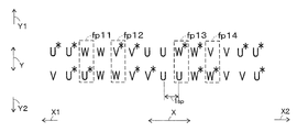
- the added value of the adjacent coil pitch obtained by adding the coil pitch of the short-pitch winding part 2SW and the coil pitch of the long-pitch winding part 2LW is obtained by dividing the number of slots by the number of pole pairs of the mover 70 (4 in this embodiment). Is set to the specified value.
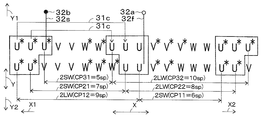
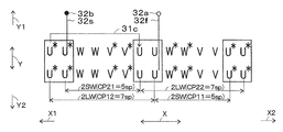
- the coil pitch CP11 between the coil sides 21 and 21 of the short-pitch winding part 2SW is set to 6 slot pitch (6sp), and the long-pitch winding part 2LW
- the coil pitch CP12 between the coil sides 21 and 21 is set to 9 slot pitch (9sp).
- the coil pitch CP11 of the short-pitch winding part 2SW is set shorter than the value (7.5) obtained by dividing the number of slots by the number of magnetic poles of the mover 70.
- the coil pitch CP12 of the long-pitch winding part 2LW is set to be longer than the value (7.5) obtained by dividing the number of slots by the number of magnetic poles of the mover 70.
- the added value of the adjacent coil pitch obtained by adding the coil pitch CP11 of the short-pitch winding part 2SW and the coil pitch CP12 of the long-pitch winding part 2LW is a value obtained by dividing the number of slots by the number of pole pairs of the mover 70 (15). Is set.
- the coil pitch CP21 between the coil sides 21 and 21 of the short-pitch winding part 2SW is set to 7 slot pitch (7sp), and between the coil sides 21 and 21 of the long-pitch winding part 2LW.
- the coil pitch CP22 is set to 8 slot pitch (8sp).
- the coil pitch CP31 between the coil sides 21 and 21 of the short-pitch winding part 2SW is set to 5 slot pitch (5sp), and the coil sides 21 and 21 of the long-pitch winding part 2LW are set.
- the coil pitch CP32 between them is set to 10 slot pitch (10sp). Therefore, the above description regarding the first unit coil 20a can be similarly applied to the second unit coil 20b and the third unit coil 20c.
- the stator coil 30 is a short-winding long-winding unit coil 20SL, and has a plurality of types (three types) of unit coils 20 (first unit coil 20a, A second unit coil 20b and a third unit coil 20c).
- a plurality (three) of unit coils 20 including one each of a plurality of types (three types) of unit coils 20 (first unit coil 20a, second unit coil 20b, and third unit coil 20c) are electrically connected. Are connected in series, and a phase coil 33 is formed.
- a plurality (three) of unit coils 20 include a plurality (two) of inter-unit coil connecting portions 31c and 31c.
- the phase coil 33 is configured by being electrically connected in series.
- the inter-unit coil connection portion 31c refers to a portion that electrically connects the unit coils 20 and 20 to each other.
- the phase coil 33 is composed of a plurality of (three) unit coils 20 (first unit coil 20a, second unit coil 20b and third unit coil 20c) constituting the phase coil 33. It is preferable that the unit coil 20a) is continuously wound from the unit coil 20a) to the unit coil 20 at the end of winding (third unit coil 20c).
- the phase coil 33 includes a pair of coil lead portions 32f and 32s each including a first coil lead portion 32f and a second coil lead portion 32s.
- the first coil lead portion 32f is drawn from the coil side 21 at the beginning of winding of the unit coil 20 at the beginning of winding (first unit coil 20a).
- the coil side 21 is defined as a first coil side 21a.
- the second coil lead portion 32s is drawn from the coil side 21 at the end of winding of the unit coil 20 at the end of winding (third unit coil 20c).
- the coil side 21 is referred to as a second coil side 21b.
- FIG. 2 shows that a plurality (three) of unit coils 20 (first unit coil 20a, second unit coil 20b, and third unit coil 20c) are wound from the first unit coil 20 (first unit coil 20a) to the end of winding.
- the phase coil 33 formed by being continuously wound around the unit coil 20 (third unit coil 20c) is shown.
- each unit coil 20 is wound toward the right side in the drawing. Since the rotating electrical machine 100 of the present embodiment is a cylindrical rotating electrical machine, each unit coil 20 makes one turn along the circumferential direction of the rotating electrical machine 100 in the first direction (the direction of the arrow X). Reach side 21.
- each unit coil 20 is wound a plurality of times along the circumferential direction of the rotating electrical machine 100 that is the first direction (the direction of the arrow X).
- the stator coil 30 includes a plurality of (three) phase coils 33 (a U-phase coil 33u, a V-phase coil 33v, and a W-phase coil 33w).
- a plurality (three) of unit coils 20 (first unit coil 20a, second unit coil 20b and third unit coil 20c) are connected in series to form a U-phase coil 33u.
- the first phase terminal 3T1 is the aforementioned winding start portion 32a
- the second phase terminal 3T2 is the aforementioned winding end portion 32b.
- V-phase coil 33v and W-phase coil 33w can be formed in the same manner as U-phase coil 33u.
- the rotating electrical machine 100 of this embodiment is a three-phase rotating electrical machine, and the U-phase coil 33u, the V-phase coil 33v, and the W-phase coil 33w are out of phase by 120 ° in electrical angle.
- the phases of the U-phase coil 33u, the V-phase coil 33v, and the W-phase coil 33w are delayed in this order.
- it is one direction in the first direction (arrow X direction), and the winding when the plurality of coil ends 22 connect the plurality of coil sides 21 so as to form a wave winding configuration in each unit coil 20.
- the direction is the wave winding direction.
- the direction which forwards in a wave winding direction be the 1st direction wave winding forward side (arrow X2 direction).
- the other direction of the first direction (arrow X direction) and the direction going backward in the wave winding direction is the first direction wave winding backward side (arrow X1 direction).
- the first direction wave winding forward side (arrow X2 direction) corresponds to the direction from the left side to the right side in FIG. 2, and the first direction wave winding backward side (arrow X1 direction) is the same. This corresponds to the direction from the right side of the drawing to the left side of the drawing.
- the plurality of (three) unit coils 20 constituting each phase coil 33 are directed from the left side to the right side in FIG.
- the wave winding direction is the first direction wave winding forward side (arrow X2 direction).
- a plurality (three) of phase coils 33 are arranged so that the phases are delayed in this order, and the phase forward direction is It is the first direction wave winding forward side (arrow X2 direction).
- the plurality of (three) unit coils 20 constituting each phase coil 33 (U-phase coil 33u, V-phase coil 33v, W-phase coil 33w) are also coincident with the phase forward direction of a plurality (three) of phase coils 33 (U-phase coil 33u, V-phase coil 33v, W-phase coil 33w).
- the three-phase phase coil 33 (U-phase coil 33u, V-phase coil 33v and W-phase coil 33w) can be electrically connected by Y connection.
- the U-phase terminal is indicated by the U-phase terminal 3TU
- the V-phase terminal is indicated by the V-phase terminal 3TV
- the W-phase terminal is indicated by the W-phase terminal 3TW.
- Phase terminals (U-phase terminal 3TU, V-phase terminal 3TV and W-phase terminal 3TW) correspond to one of first-phase terminal 3T1 and second-phase terminal 3T2
- neutral point 3N is first-phase terminal 3T1. It corresponds to the other of the second phase terminals 3T2.
- a three-phase phase coil 33 is arranged so that a half coil 23h described later is disposed on the phase terminal (U-phase terminal 3TU, V-phase terminal 3TV, and W-phase terminal 3TW) side.
- (U-phase coil 33u, V-phase coil 33v, and W-phase coil 33w) are electrically connected.
- the three-phase coil 33 (U-phase coil 33u, V-phase coil 33v, and W-phase coil 33w) can also be electrically connected by ⁇ connection.
- each phase coil 33 (U-phase coil 33u, V-phase coil 33v, W-phase coil 33w) includes a plurality (three) of unit coils 20 constituting the phase coil 33. (The first unit coil 20a, the second unit coil 20b and the third unit coil 20c) continue from the winding start unit coil 20 (first unit coil 20a) to the winding end unit coil 20 (third unit coil 20c). It is formed by being rolled up.
- the rotary electric machine 100 of this embodiment can reduce the connection site
- the plurality (three) of unit coils 20 constituting each phase coil 33 is a short-pitch winding portion 2 ⁇ / b> SW that faces one of the pair of mover magnetic poles 61 and 62.
- the coil pitch CP11 of the short winding portion 2SW of the winding start unit coil 20 (first unit coil 20a) is the minimum (6 slot pitch (6sp)).
- the unit coil 20 at the beginning of winding (first unit) so that the coil pitch CP32 of the long-pitch portion 2LW of the unit coil 20 (third unit coil 20c) at the end of winding becomes the maximum (10 slot pitch (10sp)).
- the coil pitch increases in order from the coil 20a) to the unit coil 20 at the end of winding (third unit coil 20c).
- the plurality (three) of unit coils 20 constituting each phase coil 33 includes a short-pitch portion 2SW and a long-pitch portion that face the other mover magnetic pole 62 of the pair of mover magnetic poles 61 and 62.
- the coil pitch CP12 of the long-pitch winding portion 2LW of the winding start unit coil 20 (first unit coil 20a) is the maximum (9 slot pitch (9sp))
- the coil pitch decreases in order from the last unit coil 20 (third unit coil 20c).
- the plurality of (three) unit coils 20 constituting each phase coil 33 have one end side (a pair of coil lead portions) in the third direction (arrow Z direction). It is easy to reduce the crossing between the coil ends 22 on the side from which 32f and 32s are drawn (hereinafter the same), and the other end side in the third direction (arrow Z direction) (the pair of coil lead portions 32f and 32s It is easy to reduce the crossing between the coil ends 22 on the side different from the drawn side (the same applies hereinafter).
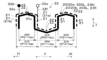
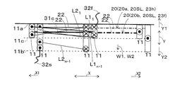
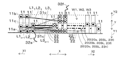
- FIG. 5A and 5B show a state where each unit coil 20 constituting the U-phase coil 33u is mounted in the plurality of slots 11, and each unit coil 20 is electrically connected in series.
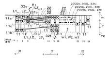
- FIG. 6 shows a state in which the phase coil 33 shown in FIG. 2 is installed in a plurality (nine) of the slots 11, and the plurality (nine) of the slots 11 includes a plurality of the slots 11 shown in FIGS. This corresponds to the slot number of the slot 11.
- 5A and 5B show a U-phase coil 33u generally facing the four magnetic poles (two magnetic pole pairs) of the mover magnetic poles. Furthermore, in FIG. 5A, in U-phase coil 33u, for convenience of explanation, a region facing one magnetic pole of mover 70 is indicated by reference numerals ⁇ U7>, ⁇ U8>, ⁇ U1>, and ⁇ U2>. .
- each unit coil 20 is indicated by “cross on circle” and “dot on circle”. “Cross mark to cross” indicates that the coil (coil side 21) is wound from the front side of the paper in the third direction (the direction of arrow Z) toward the back of the paper. “Dotted circle” indicates that the coil (coil side 21) is wound from the back side to the front side in the third direction (the arrow Z direction).
- each phase coil 33 (U-phase coil described later) 33u, V-phase coil 33v, and W-phase coil 33w) are illustrated in consideration of the assembling order. What has already been described with reference to FIGS. 5A and 5B is the same for FIGS. 7A and 7B described later. Further, in the illustrated method of the winding direction of each unit coil 20, the phase coil 33 viewed from the pair of coil lead-out portions 32 f and 32 s in the third direction (arrow Z direction) is mounted in the plurality of slots 11. This is the same in the diagrams schematically showing the state.
- the first unit coil 20a is started to be wound from the slot opening 11b side of the slot 11 of the slot number 16 from which the first coil lead portion 32f is drawn.
- the first unit coil 20a is inserted through the slot 11 having the slot number 16 from one end side in the third direction (arrow Z direction) (the side from which the pair of coil lead portions 32f and 32s are drawn), and the third direction.
- Crosses the slot 11 of slot number 22 (indicated by ⁇ U1> in FIG. 5A) via the other end side (in the direction of arrow Z) (a side different from the side from which the pair of coil lead portions 32f and 32s is drawn).
- Area the slot 11 of slot number 22 (indicated by ⁇ U1> in FIG. 5A) via the other end side (in the direction of arrow Z) (a side different from the side from which the pair of coil lead portions 32f and 32s is drawn).
- the first unit coil 20a is inserted through the slot 11 of the slot number 22 from the other end side in the third direction (arrow Z direction), and passes through one end side in the third direction (arrow Z direction) It extends to the slot 11 with the slot number 31 (area indicated by ⁇ U2> in FIG. 5A). The above is repeated for the eight magnetic poles (four magnetic pole pairs) of the mover magnetic poles.
- the first unit coil 20a is wound a plurality of times along the first direction (arrow X direction) (n times using a natural number n of 2 or more).
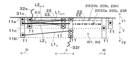
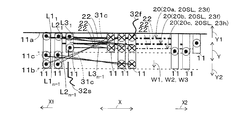
- Straight L1 1 shown in FIG. 6 shows the end of the crossover state of the coil end 22 when the first unit coil 20a is wound for the first time.
- a straight line L1 n-1 shown in the same drawing shows a transition state of the last coil end 22 when the first unit coil 20a is wound n-1 times. After the first unit coil 20a is wound n times, the first unit coil 20a passes over the second unit coil 20b via the inter-unit coil connection portion 31c.
- the first unit coil 20a is inserted through the slot 11 with the slot number 1 from one end side in the third direction (arrow Z direction), and the third direction (arrow Z direction).
- the 1st unit coil 20a has penetrated the slot 11 of the slot number 7 from the other end side of a 3rd direction (arrow Z direction).
- the first unit coil 20a extends to the slot 11 of the slot number 16 via one end side in the third direction (arrow Z direction).
- the first unit coil 20a passes through one end side in the third direction (arrow Z direction) and extends to the slot 11 of the slot number 15 (indicated by ⁇ U8> in FIG. 5A). region).
- the inter-unit coil connecting portion 31 c is routed from the slot bottom 11 a side of the slot 11 with slot number 7 to the slot opening 11 b side of the slot 11 with slot number 15.
- the second unit coil 20b is started to be wound from the slot opening 11b side of the slot 11 with the slot number 15. And the 2nd unit coil 20b has penetrated the slot 11 of the slot number 15 from the one end side of a 3rd direction (arrow Z direction), and via the other end side of a 3rd direction (arrow Z direction), It extends over the slot 11 with the slot number 23 (area indicated by ⁇ U1> in FIG. 5A). Further, the second unit coil 20b is inserted through the slot 11 of the slot number 23 from the other end side in the third direction (arrow Z direction), and passes through one end side in the third direction (arrow Z direction) It extends over the slot 11 with the slot number 30 (area indicated by ⁇ U2> in FIG. 5A). The above is repeated for the eight magnetic poles (four magnetic pole pairs) of the mover magnetic poles.
- the second unit coil 20b is wound a plurality of times (n times) along the first direction (arrow X direction).
- Straight L2 1 shown in FIG. 6 shows the end of the crossover state of the coil end 22 when the second unit coil 20b is wound for the first time.
- a straight line L2 n-1 shown in the figure shows the transition state of the last coil end 22 when the second unit coil 20b is wound n-1 times.
- the second unit coil 20b is inserted through the slot 11 of the slot number 60 from one end side in the third direction (arrow Z direction), and the third direction (arrow Z direction).
- the 2nd unit coil 20b has penetrated the slot 11 of the slot number 8 from the other end side of a 3rd direction (arrow Z direction).
- the second unit coil 20b extends to the slot 11 with the slot number 15 via one end in the third direction (arrow Z direction).
- the second unit coil 20b passes through one end side in the third direction (arrow Z direction) and extends to the slot 11 with the slot number 14 (indicated by ⁇ U8> in FIG. 5A). region).
- the inter-unit coil connecting portion 31 c is routed from the slot bottom 11 a side of the slot 11 with slot number 8 to the slot central portion 11 c of the slot 11 with slot number 14.
- the 2nd unit coil 20b is wound similarly to the 1st unit coil 20a.
- the third unit coil 20c starts to be wound from the slot central portion 11c of the slot 11 with the slot number 14.
- the third unit coil 20c is inserted through the slot 11 with the slot number 14 from one end side in the third direction (arrow Z direction), and via the other end side in the third direction (arrow Z direction), It extends to the slot 11 with the slot number 24 (area indicated by ⁇ U1> in FIG. 5A).
- the third unit coil 20c is inserted through the slot 11 with the slot number 24 from the other end side in the third direction (arrow Z direction), and passes through one end side in the third direction (arrow Z direction), It extends over the slot 11 of slot number 29 (area indicated by ⁇ U2> in FIG. 5A). The above is repeated for the eight magnetic poles (four magnetic pole pairs) of the mover magnetic poles.
- the third unit coil 20c is wound a plurality of times (n / 2 times) along the first direction (arrow X direction).
- Straight L3 1 shown in FIG. 6 shows the end of the crossover state of the coil end 22 when the third unit coil 20c is wound for the first time.
- a straight line L3 n-1 shown in the same drawing shows the transition state of the last coil end 22 when the third unit coil 20c is wound (n / 2-1) times.
- the third unit coil 20c finishes winding on the slot bottom 11a side of the slot 11 of slot number 9 from which the second coil lead portion 32s is drawn.
- the winding order of the plurality (three) of the unit coils 20 constituting the U-phase coil 33u matches the winding order indicated by the numeral * in FIG.
- the plurality (three) of unit coils 20 constituting the U-phase coil 33u are provided with two types of unit coils 20 of a full coil 23f and a half coil 23h with respect to the occupied state of the plurality (24) of the slots 11.
- the first unit coil 20a and the second unit coil 20b are full coils 23f
- the third unit coil 20c is a half coil 23h. 2 and 5A
- the full coil 23f is indicated by a solid line
- the half coil 23h is indicated by a broken line.
- the full coil 23f is configured such that when a plurality (eight) coil sides 21 of one unit coil 20 are accommodated in a plurality (eight) slots 11, the plurality (eight) coil sides 21 are included in the plurality (8).
- the unit coil 20 occupying the whole slot 11).
- the plurality of (eight) coil sides 21 have slot number 16, slot number 22, slot number 31, slot number 37, slot number 46, slot number 52, slot number 1 and slot number 7. It is accommodated in a plurality (eight) of slots 11.
- the coil side 21 accommodated in the slot 11 with the slot number 16 occupies the entire slot 11 with the slot number 16. The same applies to the other coil sides 21.
- the above description is the same for the second unit coil 20b.
- the plurality of (eight) coil sides 21 have slot number 15, slot number 23, slot number 30, slot number 38, slot number 45, slot number 53, slot number 60 and slot number 8. It is accommodated in a plurality (eight) slots 11. At this time, for example, the coil side 21 accommodated in the slot 11 with the slot number 15 occupies the entire slot 11 with the slot number 15. The same applies to the other coil sides 21.
- the half coil 23h The unit coil 20 occupying a half of each of a plurality (eight) of slots 11.
- a plurality of (eight) coil sides 21 have slot number 14, slot number 24, slot number 29, slot number 39, slot number 44, slot number 54, slot number 59 and slot number 9 respectively. It is accommodated in a plurality (eight) of slots 11. At this time, for example, the coil side 21 accommodated in the slot 11 with the slot number 14 occupies half of the slot 11 with the slot number 14. The same applies to the other coil sides 21.
- FIGS. 5B and 6 the occupied state of the slot 11 is indicated by a rectangular size.
- a large rectangle indicates that the coil side 21 of the full coil 23 f occupies the entire slot 11.
- the small rectangle indicates that the coil side 21 of the half coil 23 h occupies half of the slot 11.
- the wave winding direction of the first unit coil 20a is the first direction wave winding forward side ( Arrow X2 direction).
- the end of the coil end 22 when the first unit coil 20a is wound for the first time are arranged in the slot opening 11b side.
- the last coil end 22 when the first unit coil 20a is wound n-1 times is disposed on the slot bottom 11a side.
- the first unit coil 20a is wound a plurality of times (n times) along the first direction (arrow X direction), so that the slot opening portion in the second direction (arrow Y direction) is wound.
- a full coil 23f is formed by being wound from the 11b side to the slot bottom 11a side.
- the winding traveling direction in the second direction (arrow Y direction) at this time is defined as a winding traveling direction W1.
- the winding direction W1 in the second direction (arrow Y direction) when the full coil 23f of the first unit coil 20a is formed is the second direction slot bottom side (arrow Y1 direction).
- the wave winding direction of the second unit coil 20b is the first direction wave winding forward side (arrow X2 direction).
- the winding traveling direction in the second direction (arrow Y direction) when the full coil 23f of the second unit coil 20b is formed is defined as a winding traveling direction W2.
- the winding direction W2 in the second direction (arrow Y direction) when the full coil 23f of the second unit coil 20b is formed is the second direction slot bottom side (arrow Y1 direction).
- the wave winding direction of the third unit coil 20c is the first direction wave winding forward. Side (arrow X2 direction). Further, as shown by the straight line L3 1 in FIG. 6, the end of the coil end 22 when the third unit coil 20c is wound for the first time it is disposed in the slot central portion 11c. On the other hand, the last coil end 22 when the third unit coil 20c is wound at the (n / 2-1) th time is arranged on the slot bottom 11a side, as shown by a straight line L3 n-1 in FIG. Has been.
- the third unit coil 20c is wound a plurality of times (n / 2 times) along the first direction (arrow X direction), so that a slot is formed in the second direction (arrow Y direction).
- a half coil 23h is formed by being wound from the central portion 11c to the slot bottom portion 11a side.
- the winding traveling direction in the second direction (arrow Y direction) at this time is defined as a winding traveling direction W3.
- the winding direction W3 in the second direction (arrow Y direction) when the half coil 23h of the third unit coil 20c is formed is the second direction slot bottom side (arrow Y1 direction).
- FIG. 7A is illustrated in the same manner as FIG. 5A
- FIG. 7B is illustrated in the same manner as FIG. 5B.
- the plurality (three) of unit coils 20 constituting the V-phase coil 33v are short-winding and long-winding unit coils 20SL, and a plurality of types (three types) of units having different coil pitches CP11 to CP32.
- Coil 20 first unit coil 20a, second unit coil 20b, and third unit coil 20c).
- a plurality (three) of unit coils 20 including one each of a plurality of types (three types) of unit coils 20 are electrically connected.
- a plurality of types (three types) of unit coils 20 are electrically connected.
- the plurality (three) of unit coils 20 constituting the V-phase coil 33v includes two types of unit coils 20 of a full coil 23f and a half coil 23h with respect to the occupied state of the plurality (24) of the slots 11. Yes.
- the wave winding direction of each unit coil 20 constituting the V-phase coil 33v is the first direction wave winding forward side (arrow X2 direction).
- the plurality of (three) unit coils 20 constituting the V-phase coil 33v have winding advance directions W1, W2, and W3 in the second direction (arrow Y direction) when the full coil 23f or the half coil 23h is formed. , Both are in the second direction slot bottom (arrow Y1 direction).
- a portion corresponding to half of the slot 11 occupied by the coil side 21 disposed on the slot bottom 11a side of one of the pair of coil sides 21 and 21 of the half coil 23h One half slot portion 11d is used.
- a portion corresponding to half of the slot 11 occupied by the coil side 21 disposed on the slot opening 11b side of the other coil side 21 of the pair of coil sides 21 and 21 is defined as a second half slot. Let it be the part 11e.
- the half coil 23h of the W-phase coil 33w includes both the first half slot portion 11d and the second half slot portion 11e.
- the half coil 23h provided with both the 1st half slot part 11d and the 2nd half slot part 11e be the both-sides occupation half coil 23h1.
- the U-phase coil 33u includes the first half slot portion 11d, but does not include the second half slot portion 11e.
- the V-phase coil 33v includes the second half slot portion 11e, but does not include the first half slot portion 11d.
- each phase coil 33 (U-phase coil 33u, V-phase coil 33v, W-phase coil 33w) includes a plurality (two) of full coils 23f and one half coil 23h.
- the first unit coil 20a and the second unit coil 20b are full coils 23f
- the third unit coil 20c is a half coil 23h.
- the coil pitch configurations of the unit coils 20 are all different. Therefore, the above-described stator coil 30 can be provided in a rotating electrical machine having a fractional slot configuration.
- the plurality of (three) unit coils 20 constituting each phase coil 33 are such that the first unit coil 20a and the second unit coil 20b that are closest to each other are connected between the unit coils. It is electrically connected by the part 31c.
- the plurality of (three) unit coils 20 constituting each phase coil 33 are configured such that the second unit coil 20b and the third unit coil 20c that are closest to each other in the coil side 21 are electrically connected by the inter-unit coil connection portion 31c. It is connected to the. For example, as shown in FIG.
- the coil side 21 accommodated in the slot 11 of the slot number 16 of the first unit coil 20a is the same as the coil side 21 accommodated in the slot 11 of the slot number 14 of the third unit coil 20c. Compared to the coil side 21 housed in the slot 11 of the slot number 15 of the second unit coil 20b.
- the coil side 21 is the most in the plural (three) unit coils 20 constituting each phase coil 33 (U-phase coil 33u, V-phase coil 33v, W-phase coil 33w).
- the adjacent unit coils 20 and 20 are electrically connected. Therefore, the routing route of the inter-unit-coil connection portion 31c is simplified as compared with the case where the two unit coils 20 and 20 are connected by jumping over the unit coil 20 that the coil side 21 is closest to.
- the coil insertion machine 3I includes, for example, a plurality (three in this embodiment) of unit coils 20 (this embodiment) in units of phase coils 33 (U-phase coil 33u, V-phase coil 33v, and W-phase coil 33w). Then, it can be mounted in 24 slots 11.
- each phase coil 33 (U-phase coil 33u, V-phase coil 33v, W-phase coil 33w) includes a plurality (three) of unit coils 20 (first unit coil 20a, second unit coil 20b, and It is preferable that the third unit coil 20c) is continuously wound from the unit coil 20 at the start of winding (first unit coil 20a) to the unit coil 20 at the end of winding (third unit coil 20c). .
- the plurality of (three) unit coils 20 constituting each phase coil 33 (U-phase coil 33u, V-phase coil 33v, W-phase coil 33w) are unit coils 20 and 20 that are closest to each other in coil side 21. It is preferable that they are electrically connected.
- a plurality of (three) unit coils constituting each phase coil 33 (U-phase coil 33u, V-phase coil 33v, and W-phase coil 33w) using a winding frame and an uneven deformation jig (all not shown).
- 20 first unit coil 20a, second unit coil 20b, and third unit coil 20c).
- the plurality (three) of unit coils 20 constituting each phase coil 33 are wound in the order of the first unit coil 20a, the second unit coil 20b, and the third unit coil 20c.
- an annular coil is formed by winding a coil in an annular shape using a cylindrical winding frame.
- the coil is wound so that the winding direction of the coil viewed from the winding start portion 32a side in the axial direction of the winding frame is clockwise.
- the number of turns of the coil corresponding to the first unit coil 20a is n
- the number of turns of the coil corresponding to the second unit coil 20b is n
- the number of turns of the coil corresponding to the third unit coil 20c is n. / 2 times. That is, the coil is wound (n ⁇ 2 + n / 2) times.
- the annular coil is deformed from the direction indicated by the arrow Fa as shown in FIG.
- part corresponded to the some coil side 21 of each unit coil 20, and the site
- Each site is formed.
- the plurality of (three) unit coils 20 constituting each phase coil 33 are all different in the combination of the coil pitches of the short-pitch portion 2SW and the long-pitch portion 2LW. Therefore, three types of uneven deformation jigs are required.
- the first coil side 21a from which the first coil lead portion 32f is drawn is on the back side (lower side) of the drawing
- the second coil side 21b from which the two-coil drawing portion 32s is drawn is the front side (upper side) of the drawing.
- the winding traveling directions W1, W2, and W3 of the unit coils 20 of the phase coil 33 are all directions from the back side (lower side) to the front side (upper side) of the page.
- the coil insertion machine 3I includes an inserter blade 3B that holds each unit coil 20 of the phase coil 33.
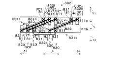
- the inserter blade 3B includes a plurality of comb-shaped support portions 3B1 in which the slot pitch between the slots 11 and 11 is reflected.
- a plurality of (three) unit coils 20 constituting the U-phase coil 33u are dropped into the support portion 3B1 of the inserter blade 3B, and a plurality (three) unit coils 20 constituting the U-phase coil 33u are formed. Grasped.
- the inserter blade 3B is inserted inward of the stator core 10, and a plurality (three) of unit coils 20 constituting the U-phase coil 33u are inserted into each slot at a time. 11 is inserted.
- the winding advance direction W1 of the first unit coil 20a is on the bottom side of the second direction slot (arrow Y1 direction), and the full coil 23f is formed. Is done. The same applies to the winding traveling direction W2 of the second unit coil 20b. Further, when the third unit coil 20c is accommodated in a plurality (eight) of the slots 11, the winding traveling direction W3 of the third unit coil 20c becomes the second direction slot bottom (arrow Y1 direction), and the half coil 23h is formed.
- the U-phase coil 33u viewed from the pair of coil lead-out portions 32f and 32s (the lower side in the drawing in these drawings) in the third direction (the arrow Z direction).
- the wave winding direction of each unit coil 20 is clockwise.
- the wave winding direction of each unit coil 20 constituting the U-phase coil 33u shown in FIG. 5A is clockwise and coincides with the wave winding direction shown in FIGS. 8A and 8B. . That is, the wave winding direction of each unit coil 20 constituting the U-phase coil 33u is on the first direction wave winding forward side (arrow X2 direction).
- the winding start portion 32a of the phase coil 33 is provided on the slot opening 11b side
- the winding end portion 32b of the phase coil 33 is provided on the slot bottom portion 11a side.
- the stator coil 30 is assembled in the order of the U-phase coil 33u, the W-phase coil 33w, and the V-phase coil 33v. Then, each phase terminal (3TU, 3TV, 3TW) and the neutral point 3N are connected. Further, the plurality of coil ends 22 of the plurality of unit coils 20 constituting each phase coil 33, a plurality (two) of inter-unit coil connection portions 31c, 31c, and a pair of coil lead portions 32f, 32s (first coil lead portions) After the lace binding of 32f and the second coil lead portion 32s), the stator coil 30 is fixed to the stator core 10 by varnish impregnation, resin molding, or the like.
- a plurality of (three) unit coils 20 that constitute each phase coil 33 are full coils 23f.
- the winding traveling directions W1, W2, and W3 in the second direction (arrow Y direction) when the half coil 23h is formed are all on the second direction slot bottom side (arrow Y1 direction). Therefore, the rotating electrical machine 100 of the present embodiment uses a coil insertion machine 3I (inserter jig), for example, in units of phase coils 33 (U-phase coil 33u, V-phase coil 33v, and W-phase coil 33w).
- Three (3) unit coils 20 can be mounted in a plurality (24) of the slots 11.
- a plurality of (three) unit coils 20 constituting each phase coil 33 are dropped into the support portion 3B1 of the inserter blade 3B, and the plurality (three) unit coils 20 are gripped, A plurality (three) of unit coils 20 can be inserted into each slot 11 and attached at a time. That is, the rotating electrical machine 100 according to the present embodiment has the performance of the rotating electrical machine as compared with the double layer winding (which is difficult to mount in the above-described phase coil 33 unit) that is generally implemented in the rotating electrical machine having a fractional slot configuration. The work man-hours required for assembling the stator coil 30 can be reduced while maintaining substantially the same.
- a plurality (nine) of unit coils 20 constituting a plurality (three) of phase coils 33 are a plurality (six) of two phases.
- the unit coils 20 can be continuously wound to form the phase coils 33 and 33 for two phases.
- the phase coils 33 and 33 for two phases can be attached at a time, and the number of work steps required for assembling the stator coil 30 can be further reduced as compared with the present embodiment.
- the number of connection points of the neutral point 3N can be reduced as compared with the present embodiment.
- the first coil lead-out portion 32 f is one coil side 21 (first coil side) that forms the short-pitch winding portion 2 ⁇ / b> SW of the winding start unit coil 20 (first unit coil 20 a).
- 21a which is preferably drawn from a side different from the side where the coil end 22 forming the short-pitch winding part 2SW is provided, in one end side and the other end side in the third direction (arrow Z direction). It is.
- the winding start unit coil 20 (first unit coil 20a) is composed of the coil pitch of the long-pitch winding part 2LW and the coil of the short-pitch winding part 2SW among the plural (two) full coils 23f constituting the phase coil 33. It is preferable that the full coil 23f has the largest difference from the pitch.
- the first coil lead portion 32 f is drawn from the slot opening portion 11 b side.
- the second coil lead-out part 32s is one coil side 21 (second coil side 21b) that forms the short-pitch winding part 2SW of the unit coil 20 (third unit coil 20c) at the end of winding, and is in the third direction ( It is preferable that the coil end 22 is drawn from the same side as the side where the coil end 22 forming the short-pitch winding portion 2SW is provided on one end side and the other end side in the arrow Z direction.
- the unit coil 20 at the end of winding (third unit coil 20 c) is preferably a single half coil 23 h constituting the phase coil 33.
- the second coil lead portion 32 s is drawn from the slot bottom portion 11 a side.
- one unit inter-coil connection portion 31c among the plurality (two) inter-unit coil connection portions 31c, 31c and the second coil lead portion 32s are slightly Intersecting interference.
- the inter-unit coil connection part 31c that connects the second unit coil 20b and the third unit coil 20c is close to the second coil lead part 32s. Therefore, the coil end 22 of the second unit coil 20b and the coil end 22 of the third unit coil 20c may be slightly detoured toward the second direction slot opening (arrow Y2 direction).
- the inter-unit coil connection portion 31c that connects the second unit coil 20b and the third unit coil 20c can be slightly detoured toward the second direction slot opening (arrow Y2 direction). Therefore, the interference crossing between the unit coil connection part 31c and the second coil lead part 32s can be avoided.
- the inter-unit coil connecting portion 31c that connects the first unit coil 20a and the second unit coil 20b can be accommodated between the coil ends 22 and 22 of the first unit coil 20a and the second unit coil 20b.
- the inter-unit coil connecting portion 31c that connects the second unit coil 20b and the third unit coil 20c can be accommodated between the coil ends 22 and 22 of the second unit coil 20b and the third unit coil 20c.
- the first coil lead-out portion 32f can also cross the outer side (the front side in the drawing) of the coil end 22 of the first unit coil 20a in the third direction (arrow Z direction).
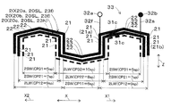
- the arrangement of the pair of coil lead portions 32f and 32s can be the arrangement of the first modification.
- the coil pitch configuration of the first unit coil 20a corresponds to the coil pitch configuration of the third unit coil 20c of the present embodiment.
- the coil pitch configuration of the second unit coil 20b corresponds to the coil pitch configuration of the second unit coil 20b of the present embodiment.
- the coil pitch configuration of the third unit coil 20c corresponds to the coil pitch configuration of the first unit coil 20a of the present embodiment.
- the wave winding direction of each unit coil 20 (first unit coil 20a, second unit coil 20b, third unit coil 20c) constituting each phase coil 33 is the first direction wave winding forward side (arrow X2 direction).
- the first unit coil 20a is a half coil 23h
- the second unit coil 20b and the third unit coil 20c are full coils 23f.
- the winding traveling direction W1 in the second direction (arrow Y direction) when the half coil 23h is formed is the second direction slot bottom side (arrow Y1 direction).
- the winding traveling direction W2 in the second direction (arrow Y direction) when the full coil 23f is formed is the second direction slot bottom side (arrow Y1 direction).
- the winding traveling direction W3 in the second direction (arrow Y direction) when the full coil 23f is formed is the second direction slot bottom side (arrow Y1 direction).
- the first coil lead-out portion 32f is one coil side 21 (first coil side 21a) that forms the long-pitch winding portion 2LW of the winding start unit coil 20 (first unit coil 20a).
- the coil end 22 is drawn from a side different from the side where the coil end 22 forming the long winding portion 2LW is provided.
- the winding start unit coil 20 (first unit coil 20 a) is one half coil 23 h constituting the phase coil 33.
- the first coil lead portion 32f is drawn from the slot central portion 11c.
- the second coil lead-out part 32s is one coil side 21 (second coil side 21b) that forms the long-pitch winding part 2LW of the unit coil 20 (third unit coil 20c) at the end of winding, and is in the third direction ( Of the one end side and the other end side (in the direction of arrow Z), it is drawn from the same side as the side on which the coil end 22 forming the long-pitch winding portion 2LW is provided.
- the winding end unit coil 20 (third unit coil 20c) includes a coil pitch of the long winding portion 2LW and a short pitch winding portion 2SW of the plural (two) full coils 23f constituting the phase coil 33. The difference from the coil pitch is the maximum full coil 23f.
- the second coil lead portion 32s is drawn from the slot bottom portion 11a side.
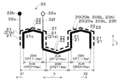
- the first unit coil 20a (the coil pitch CP11 is the smallest coil pitch). Winding is started from 5 slot pitch (5sp). Then, on the side of the pair of coil lead portions 32f and 32s in the third direction (arrow Z direction), the coil is wound at the third unit coil 20c having the maximum coil pitch (coil pitch CP32, 9 slot pitch (9sp)). End. In this way, the first unit coil 20a, the second unit coil 20b, and the third unit coil 20c are continuously wound in this order, and the stator core 10 is formed using the coil insertion machine 3I (inserter jig).
- the first coil lead portion 32f When assembled in the plurality of slots 11, the first coil lead portion 32f is drawn to the slot opening portion 11b side. That is, the arrangement of the first coil lead-out portion 32f needs to bypass the plural (two) inter-unit coil connection portions 31c and 31c and the other unit coils 20 (the second unit coil 20b and the third unit coil 20c).
- the first coil lead-out portion 32f protrudes toward the second direction slot opening (arrow Y2 direction).
- each phase coil 33 of this modification is enlarged in the third direction (arrow Z direction) as compared with the present embodiment.
- the first coil lead portion 32f can also be drawn from the slot opening portion 11b side toward the second direction slot bottom side (arrow Y1 direction).
- the arrangement of the pair of coil lead portions 32f and 32s can be the arrangement of the second modification.
- the first unit coil 20a has a coil pitch CP11 of the short-pitch winding part 2SW set to 5 slot pitch (5sp), and a coil pitch CP12 of the long-pitch winding part 2LW set to 10 slot pitch (10sp).
- the coil pitch CP21 of the short-pitch winding part 2SW is set to 7 slot pitch (7sp)
- the coil pitch CP22 of the long-pitch winding part 2LW is set to 8 slot pitch (8sp).
- the coil pitch CP31 of the short-pitch winding part 2SW is set to 6 slot pitch (6sp), and the coil pitch CP32 of the long-pitch winding part 2LW is set to 9 slot pitch (9sp). .
- the wave winding direction of each unit coil 20 (first unit coil 20a, second unit coil 20b, third unit coil 20c) constituting each phase coil 33 is the first direction wave winding forward side (arrow X2 direction).
- the first unit coil 20a is a half coil 23h
- the second unit coil 20b and the third unit coil 20c are full coils 23f.
- the winding traveling direction W1 in the second direction (arrow Y direction) when the half coil 23h is formed is the second direction slot bottom side (arrow Y1 direction).
- the winding traveling direction W2 in the second direction (arrow Y direction) when the full coil 23f is formed is the second direction slot bottom side (arrow Y1 direction).
- the winding traveling direction W3 in the second direction (arrow Y direction) when the full coil 23f is formed is the second direction slot bottom side (arrow Y1 direction).
- the first coil lead portion 32f is one coil side 21 (first coil side 21a) that forms the short-pitch winding portion 2SW of the winding start unit coil 20 (first unit coil 20a). Of the one end side and the other end side in the third direction (arrow Z direction), it is drawn from a side different from the side where the coil end 22 forming the short-pitch winding part 2SW is provided.
- the winding start unit coil 20 (first unit coil 20 a) is one half coil 23 h constituting the phase coil 33.
- the first coil lead portion 32f is drawn from the slot central portion 11c.
- the second coil lead-out portion 32 s is one coil side 21 (second coil side 21 b) that forms the short-pitch winding portion 2 SW of the unit coil 20 (third unit coil 20 c) at the end of winding, and is in the third direction ( Of the one end side and the other end side (in the direction of arrow Z), the coil end 22 is drawn from the same side as the side where the coil end 22 forming the short-pitch winding portion 2SW is provided.
- the winding end unit coil 20 (third unit coil 20c) includes a coil pitch of the long winding portion 2LW and a short pitch winding portion 2SW of the plural (two) full coils 23f constituting the phase coil 33. The difference from the coil pitch is the maximum full coil 23f.
- the second coil lead portion 32s is drawn from the slot bottom portion 11a side.
- one unit coil connection part 31c of the plural (two) unit coil connection parts 31c, 31c and the second coil lead part 32s are slightly Intersecting interference.
- the inter-unit coil connection part 31c that connects the second unit coil 20b and the third unit coil 20c is close to the second coil lead part 32s. Therefore, it is good to avoid the interference crossing between the unit coil connection part 31c and the second coil lead part 32s as in the present embodiment.
- the inter-unit coil connecting portion 31c that connects the first unit coil 20a and the second unit coil 20b can be accommodated between the coil ends 22 and 22 of the first unit coil 20a and the second unit coil 20b.
- the inter-unit coil connecting portion 31c that connects the second unit coil 20b and the third unit coil 20c can be accommodated between the coil ends 22 and 22 of the second unit coil 20b and the third unit coil 20c.
- the first coil lead portion 32f can also be drawn from the slot center portion 11c to the second direction slot bottom side (arrow Y1 direction).
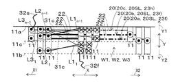
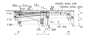
- the angle (inclination angle ⁇ 2 shown in FIG. 12) formed by the drawing direction of the inter-unit coil connection portion 31c and the first direction (arrow X direction) is the angle formed by the above embodiment (FIG. 6). Is larger than the inclination angle ⁇ 1) shown in FIG. Therefore, in this modification, the interference crossing between the unit coil connection part 31c and the second coil lead part 32s is reduced as compared with the present embodiment.
- the arrangement of the pair of coil lead portions 32f and 32s can be the arrangement of the third modification.
- the coil pitch configuration of the first unit coil 20a corresponds to the coil pitch configuration of the third unit coil 20c of the second modification.
- the coil pitch configuration of the second unit coil 20b corresponds to the coil pitch configuration of the second unit coil 20b of the second modification.
- the coil pitch configuration of the third unit coil 20c corresponds to the coil pitch configuration of the first unit coil 20a of the second modification.
- the wave winding direction of each unit coil 20 (first unit coil 20a, second unit coil 20b, third unit coil 20c) constituting each phase coil 33 is the first direction wave winding forward side (arrow X2 direction).
- the first unit coil 20a and the second unit coil 20b are full coils 23f
- the third unit coil 20c is a half coil 23h.
- the winding traveling direction W1 in the second direction (arrow Y direction) when the full coil 23f is formed is the second direction slot bottom side (arrow Y1 direction).
- the winding traveling direction W2 in the second direction (arrow Y direction) when the full coil 23f is formed is the second direction slot bottom side (arrow Y1 direction).
- the winding traveling direction W3 in the second direction (arrow Y direction) when the half coil 23h is formed is the second direction slot bottom side (arrow Y1 direction).
- the first coil lead-out portion 32f is one coil side 21 (first coil side 21a) that forms the long-pitch winding portion 2LW of the winding start unit coil 20 (first unit coil 20a).
- the coil end 22 is drawn from a side different from the side where the coil end 22 forming the long winding portion 2LW is provided.
- the winding start unit coil 20 (first unit coil 20a) is composed of the coil pitch of the long-pitch winding part 2LW and the coil of the short-pitch winding part 2SW among the plural (two) full coils 23f constituting the phase coil 33.
- the full coil 23f has the largest difference from the pitch.
- the first coil lead portion 32f is drawn from the slot opening portion 11b side.
- the second coil lead-out part 32s is one coil side 21 (second coil side 21b) that forms the long-pitch winding part 2LW of the unit coil 20 (third unit coil 20c) at the end of winding, and is in the third direction ( Of the one end side and the other end side (in the direction of arrow Z), it is drawn from the same side as the side on which the coil end 22 forming the long-pitch winding portion 2LW is provided.
- the unit coil 20 at the end of winding (third unit coil 20 c) is one half coil 23 h constituting the phase coil 33.
- the second coil lead portion 32s is drawn from the slot bottom portion 11a side.
- one unit coil connection part 31c of the plurality (two) unit coil connection parts 31c, 31c and the first coil lead part 32f are slightly Intersecting interference. Specifically, the inter-unit coil connection part 31c that connects the first unit coil 20a and the second unit coil 20b is close to the first coil lead part 32f. Therefore, it is good to avoid the interference crossing between the unit coil connection part 31c and the first coil lead part 32f as in the present embodiment.
- the inter-unit coil connecting portion 31c that connects the first unit coil 20a and the second unit coil 20b can be accommodated between the coil ends 22 and 22 of the first unit coil 20a and the second unit coil 20b.
- the inter-unit coil connecting portion 31c that connects the second unit coil 20b and the third unit coil 20c can be accommodated between the coil ends 22 and 22 of the second unit coil 20b and the third unit coil 20c.
- the first coil lead portion 32f can be drawn from the slot opening portion 11b to the second direction slot bottom side (arrow Y1 direction).
- each phase coil 33 (U-phase coil 33u, V-phase coil 33v, W-phase coil 33w) is the winding start unit coil 20 (first unit coil 20a). Pulled out from the first coil lead portion 32f drawn from the coil side 21 (first coil side 21a) and the coil side 21 (second coil side 21b) at the end of winding of the unit coil 20 at the end of winding (third unit coil 20c). A pair of coil lead portions 32f and 32s including a second coil lead portion 32s. Furthermore, the first coil lead portion 32f is one coil side 21 (first coil side 21a) that forms the short-pitch winding portion 2SW of the winding start unit coil 20 (first unit coil 20a).
- the second coil lead-out portion 32s is one coil side 21 (second coil side 21b) that forms the short-pitch winding portion 2SW of the winding end unit coil 20 (third unit coil 20c).
- second coil side 21b second coil side 21b
- third unit coil 20c third unit coil 20c
- the amount of detour in the second direction (arrow Y direction) of the pair of coil lead portions 32f and 32s can be reduced, and the lead path of the pair of coil lead portions 32f and 32s can be simplified. That is, the interference crossing between the plurality of (two) inter-unit coil connection portions 31c and 31c and the coil ends 22 of the unit coils 20 and the pair of coil lead portions 32f and 32s is reduced. As a result, in each phase coil 33, the coil ends 22 on the side of the pair of coil lead portions 32f and 32s in the third direction (arrow Z direction) are reduced in size, and the arrangement thereof is simplified.
- the said structure is similarly equipped with the rotary electric machine 100 of a 2nd modification.
- the coil end length ratio is the length of the coil end 22 facing the mover magnetic pole (mover magnetic pole 61 or mover magnetic pole 62) corresponding to one magnetic pole of the plurality of (three) unit coils 20 constituting the phase coil 33.
- the sum of The coil end length ratio is the sum of the lengths of the coil ends 22 in slot pitch units per unit number of turns of the unit coil 20, and is calculated in consideration of the number of turns of the full coil 23f and the half coil 23h. When the number of turns of the full coil 23f is 1, the number of turns of the half coil 23h is 1/2 (turn ratio 1/2).
- the coil pitch CP11 of the short-pitch winding part 2SW of the first unit coil 20a facing the mover magnetic pole 61 is 6 slot pitch (6sp), and the second unit coil 20b.
- the coil pitch CP22 of the long winding portion 2LW is 8 slot pitch (8sp)
- the coil pitch CP12 of the long winding portion 2LW of the first unit coil 20a facing the mover magnetic pole 62 is 9 slot pitch (9sp)
- the coil pitch CP21 of the short winding portion 2SW of the second unit coil 20b is 9 slot pitch (9sp)
- the coil pitch CP21 of the short winding portion 2SW of the second unit coil 20b is a 7-slot pitch (7sp)
- the coil end length ratios at both ends in the third direction (arrow Z direction) are substantially the same.
- the coil pitch CP11 of the short-pitch winding part 2SW of the first unit coil 20a is 5 slot pitch (5sp), and the short-pitch winding of the second unit coil 20b.
- the coil pitch CP21 of the part 2SW is 7 slot pitch (7sp)
- the coil pitch CP12 of the long-pitch portion 2LW of the first unit coil 20a is 10 slot pitch (10sp)
- the coil pitch CP22 of the long-pitch portion 2LW of the second unit coil 20b is 8 slot pitch (8sp).
- the state of interference crossing between the plurality (two) of inter-unit coil connection portions 31c and 31c and the pair of coil lead portions 32f and 32s is substantially the same.
- the coil end length ratio at both ends in the direction (arrow Z direction) is substantially the same.
- the stator coil 30 of the present embodiment is more suitable than the stator coil 30 of the second modified form.
- each cross-sectional area of the pair of coil sides 21 and 21 of the half coil 23h is about half of each cross-sectional area of the pair of coil sides 21 and 21 of the full coil 23f, and the half coil 23h includes the full coil 23f and Compared to half the required storage space. Furthermore, since the minimum bending radius (bending radius) and bending deformation operating force of the half coil 23h are smaller than those of the full coil 23f, the half coil 23h is easier to accommodate and adjust than the full coil 23f.
- each phase coil 33 (U-phase coil 33u, V-phase coil 33v, W-phase coil 33w) is a plurality of (two) full coils 23f constituting the phase coil 33.
- the full coil 23f having the largest difference between the coil pitch of the long-pitch winding part 2LW and the coil pitch of the short-pitch winding part 2SW is the unit coil 20 (first unit coil 20a) at the beginning of winding, and constitutes the phase coil 33.
- One half coil 23h is the unit coil 20 (third unit coil 20c) at the end of winding.
- the coil end 22 of the half coil 23h is accommodated inside the coil end 22 of the full coil 23f on one end side in the third direction (arrow Z direction) (the side from which the pair of coil lead portions 32f and 32s is drawn).
- the coil end 22 on one end side in the third direction (arrow Z direction) can be reduced in size by utilizing an empty space inside the full coil 23f.
- the stator coil 30 according to the present embodiment is mainly described from such a viewpoint.
- the stator coil 30 according to another modified form such as the stator coil 30 according to the second modified form. May be applied as appropriate.
- the height of the coil end 22 can be made more uniform including the arrangement of the pair of coil lead portions 32f and 32s at both ends in the third direction (arrow Z direction), which is preferable in terms of volume efficiency. It may become.
- the preferred arrangement of the pair of coil lead portions 32f and 32s in each phase coil 33 has a similar tendency even when the number of slots per phase per pole is 1.5.
- the rotating electrical machine 100 of the fourth modification is a three-phase rotating electrical machine having an 8-pole 36-slot configuration, and the number of slots per phase per pole is 1.5.
- the stator coil 30 is a short-winding long-winding winding unit coil 20SL, and has a plurality of types (two types) of different coil pitches CP11 to CP22.
- a unit coil 20 is provided.
- the stator coil 30 includes a plurality (3) of phase coils 33 in which a plurality (two) of unit coils 20 including one each of a plurality of types (two types) of unit coils 20 are electrically connected in series.
- each phase coil 33 includes a unit coil 20 (first unit coil 20a) from which the plurality of (two) unit coils 20 constituting the phase coil 33 are wound, and a unit coil 20 (second unit coil 20b) from which winding ends. ) Is continuously wound and formed.
- the first unit coil 20a has the coil pitch CP11 of the short-pitch portion 2SW set to 4 slot pitch (4sp), and the coil pitch CP12 of the long-pitch portion 2LW set to 5 slot pitch (5sp). Is set.
- the coil pitch CP21 of the short-pitch winding part 2SW is set to 3 slot pitch (3sp)
- the coil pitch CP22 of the long-pitch winding part 2LW is set to 6 slot pitch (6sp). .
- each unit coil 20 (first unit coil 20a, second unit coil 20b) constituting each phase coil 33 is the first direction wave winding forward side (arrow X2 direction).
- the first unit coil 20a is a full coil 23f
- the second unit coil 20b is a half coil 23h.
- the winding traveling direction W1 in the second direction (arrow Y direction) when the full coil 23f is formed is the second direction slot bottom side (arrow Y1 direction).
- the winding traveling direction W2 in the second direction (arrow Y direction) when the half coil 23h is formed is the second direction slot bottom side (arrow Y1 direction).
- the first coil lead-out portion 32f is one coil side 21 that forms the short-pitch winding portion 2SW of the winding start unit coil 20 (first unit coil 20a).
- First coil side 21a which is pulled out from a side different from the side where the coil end 22 forming the short-pitch winding portion 2SW is provided on one end side and the other end side in the third direction (arrow Z direction). It is.
- the winding start unit coil 20 (first unit coil 20 a) is one full coil 23 f constituting the phase coil 33.
- the first coil lead portion 32f is drawn from the slot opening portion 11b side.
- the second coil lead-out portion 32 s is one coil side 21 (second coil side 21 b) that forms the short-pitch winding portion 2 SW of the unit coil 20 (second unit coil 20 b) at the end of winding, and is in the third direction ( Of the one end side and the other end side (in the direction of arrow Z), the coil end 22 is drawn from the same side as the side where the coil end 22 forming the short-pitch winding portion 2SW is provided. Further, the winding end unit coil 20 (second unit coil 20 b) is one half coil 23 h constituting the phase coil 33. In FIG. 16, the second coil lead portion 32s is drawn from the slot bottom portion 11a side.
- each phase coil 33 of the fourth modification the number of full coils 23f is reduced by one and the number of inter-unit coil connection portions 31c is reduced by one compared to each phase coil 33 of the present embodiment.
- the state of interference crossing between the pair of coil lead portions 32f and 32s and the inter-unit coil connection portion 31c is the same as that of the present embodiment.
- the arrangement of the pair of coil lead portions 32f and 32s can be the arrangement of the fifth modification.
- the coil pitch configuration of the first unit coil 20a corresponds to the coil pitch configuration of the second unit coil 20b of the fourth modification.
- the coil pitch configuration of the second unit coil 20b corresponds to the coil pitch configuration of the first unit coil 20a of the fourth modification.
- the wave winding direction of each unit coil 20 (first unit coil 20a and second unit coil 20b) constituting each phase coil 33 is the first direction wave winding forward side (arrow X2 direction).
- the first unit coil 20a is a half coil 23h
- the second unit coil 20b is a full coil 23f.
- the winding traveling direction W1 in the second direction (arrow Y direction) when the half coil 23h is formed is the second direction slot bottom side (arrow Y1 direction).
- the winding traveling direction W2 in the second direction (arrow Y direction) when the full coil 23f is formed is the second direction slot bottom side (arrow Y1 direction).
- the first coil lead-out portion 32f is one coil side 21 (first coil side 21a) that forms the long-pitch winding portion 2LW of the winding start unit coil 20 (first unit coil 20a).
- the coil end 22 is drawn from a side different from the side where the coil end 22 forming the long winding portion 2LW is provided.
- the winding start unit coil 20 (first unit coil 20 a) is one half coil 23 h constituting the phase coil 33.
- the first coil lead portion 32f is drawn from the slot central portion 11c.
- the second coil lead-out portion 32s is one coil side 21 (second coil side 21b) that forms the long-pitch winding portion 2LW of the winding end unit coil 20 (second unit coil 20b), and is in the third direction ( Of the one end side and the other end side (in the direction of arrow Z), the coil end 22 is drawn from the same side as the side where the coil end 22 forming the long joint winding portion 2LW is provided.
- the unit coil 20 at the end of winding (second unit coil 20 b) is one full coil 23 f constituting the phase coil 33.
- the second coil lead portion 32s is drawn from the slot bottom portion 11a side.
- each phase coil 33 of the fifth modification the number of full coils 23f is reduced by one and the number of unit coil inter-connection portions 31c is reduced by one compared to each phase coil 33 of the first modification.
- the state of the interference intersection between the pair of coil lead portions 32f and 32s and the inter-unit coil connection portion 31c is the same.
- the arrangement of the pair of coil lead portions 32f and 32s can be the arrangement of the sixth modification.
- the first unit coil 20a has the coil pitch CP11 of the short-pitch portion 2SW set to 4 slot pitch (4sp), and the coil pitch CP12 of the long-pitch portion 2LW set to 5 slot pitch (5sp).
- the coil pitch CP21 of the short-pitch winding part 2SW is set to 3 slot pitch (3sp)
- the coil pitch CP22 of the long-pitch winding part 2LW is set to 6 slot pitch (6sp).
- the wave winding direction of each unit coil 20 (first unit coil 20a and second unit coil 20b) constituting each phase coil 33 is the first direction wave winding forward side (arrow X2 direction).
- the first unit coil 20a is a half coil 23h
- the second unit coil 20b is a full coil 23f.
- the winding traveling direction W1 in the second direction (arrow Y direction) when the half coil 23h is formed is the second direction slot bottom side (arrow Y1 direction).
- the winding traveling direction W2 in the second direction (arrow Y direction) when the full coil 23f is formed is the second direction slot bottom side (arrow Y1 direction).
- the first coil lead portion 32f is one coil side 21 (first coil side 21a) that forms the short-pitch winding portion 2SW of the winding start unit coil 20 (first unit coil 20a). Of the one end side and the other end side in the third direction (arrow Z direction), it is drawn from a side different from the side where the coil end 22 forming the short-pitch winding part 2SW is provided.
- the winding start unit coil 20 (first unit coil 20 a) is one half coil 23 h constituting the phase coil 33. In FIG. 20, the first coil lead portion 32f is drawn from the slot central portion 11c.
- the second coil lead-out portion 32 s is one coil side 21 (second coil side 21 b) that forms the short-pitch winding portion 2 SW of the unit coil 20 (second unit coil 20 b) at the end of winding, and is in the third direction ( Of the one end side and the other end side (in the direction of arrow Z), the coil end 22 is drawn from the same side as the side where the coil end 22 forming the short-pitch winding portion 2SW is provided.
- the unit coil 20 at the end of winding (second unit coil 20 b) is one full coil 23 f constituting the phase coil 33. In FIG. 20, the second coil lead portion 32s is drawn from the slot bottom portion 11a side.
- each phase coil 33 of the sixth modification the number of full coils 23f is reduced by one and the number of unit coil inter-connection portions 31c is reduced by one compared to each phase coil 33 of the second modification.
- the state of the interference intersection between the pair of coil lead portions 32f and 32s and the inter-unit coil connection portion 31c is the same.
- the angle (inclination angle ⁇ 4 shown in FIG. 20) formed by the drawing direction of the inter-unit coil connection portion 31c and the first direction (arrow X direction) is the angle formed by the above-described fourth modification ( It is larger than the inclination angle ⁇ 3) shown in FIG. Therefore, in this modification, the interference crossing between unit coil connection part 31c and the 2nd coil extraction part 32s is reduced compared with the 4th modification.
- the arrangement of the pair of coil lead portions 32f and 32s can be the arrangement of the seventh modification.
- the coil pitch configuration of the first unit coil 20a corresponds to the coil pitch configuration of the second unit coil 20b of the sixth modification.
- the coil pitch configuration of the second unit coil 20b corresponds to the coil pitch configuration of the first unit coil 20a of the sixth modification.
- the wave winding direction of each unit coil 20 (first unit coil 20a and second unit coil 20b) constituting each phase coil 33 is the first direction wave winding forward side (arrow X2 direction).
- the first unit coil 20a is a full coil 23f
- the second unit coil 20b is a half coil 23h.
- the winding traveling direction W1 in the second direction (arrow Y direction) when the full coil 23f is formed is the second direction slot bottom side (arrow Y1 direction).
- the winding traveling direction W2 in the second direction (arrow Y direction) when the half coil 23h is formed is the second direction slot bottom side (arrow Y1 direction).
- the first coil lead-out portion 32f is one coil side 21 (first coil side 21a) that forms the long-pitch winding portion 2LW of the winding start unit coil 20 (first unit coil 20a).
- the coil end 22 is drawn from a side different from the side where the coil end 22 forming the long winding portion 2LW is provided.
- the winding start unit coil 20 (first unit coil 20 a) is one full coil 23 f constituting the phase coil 33.
- the first coil lead portion 32f is drawn from the slot opening portion 11b side.
- the second coil lead-out portion 32s is one coil side 21 (second coil side 21b) that forms the long-pitch winding portion 2LW of the winding end unit coil 20 (second unit coil 20b), and is in the third direction ( Of the one end side and the other end side (in the direction of arrow Z), the coil end 22 is drawn from the same side as the side where the coil end 22 forming the long joint winding portion 2LW is provided.
- the unit coil 20 at the end of winding (second unit coil 20 b) is one half coil 23 h constituting the phase coil 33. In FIG. 22, the second coil lead portion 32s is drawn from the slot bottom portion 11a side.
- each phase coil 33 of the seventh modification has one fewer full coil 23f than each phase coil 33 of the third modification, and the inter-unit coil connection portion 31c. Decreases by one. As a result, as shown in FIG. 22, in the seventh modification, the interference crossing between the first coil lead part 32f and the inter-unit coil connection part 31c is eliminated.
- each phase coil 33 has the number of full coils 23f and the number of connection portions 31c between unit coils as compared to the case where the number of slots per phase per pole is 2.5. Increases by one.
- the arrangement of the pair of coil lead portions 32f and 32s in each phase coil 33 is the same as that described above, the interference crossing between the pair of coil lead portions 32f and 32s and the inter-unit coil connection portion 31c. The state is substantially the same. That is, even when the number of slots per phase per pole is 3.5 or more, the preferred arrangement of the pair of coil lead portions 32f and 32s in each phase coil 33 is the same as when the number of slots per phase per pole is 2.5. It is.
- a plurality (three in this embodiment) of phase coils 33 include a first phase mounting step, a second phase leading phase mounting step, and a third phase leading phase. It is preferable that a plurality of (60) slots 11 are mounted by a method of manufacturing the rotating electrical machine 100 including the mounting step. Thereby, in this embodiment, the plurality (three) of phase coils 33 are assembled in the order of the U-phase coil 33u, the W-phase coil 33w, and the V-phase coil 33v.
- phase of the plural (three) phase coils 33 is assumed to be delayed in the order of the U-phase coil 33u, the V-phase coil 33v, and the W-phase coil 33w.
- a plurality (three) of the phase coils 33 are arranged in the phase order of the U-phase coil 33u, the V-phase coil 33v, and the W-phase coil 33w on the first-direction wave winding forward side (in the direction of the arrow X2). To do.
- one phase coil 33 (in this embodiment, U-phase coil 33u) out of a plurality (three) of phase coils 33 is replaced with a plurality (24) of slots 11. It is the process of attaching to.
- the figure shows the mounting state of a plurality (three) of unit coils 20 for approximately two magnetic pole pairs constituting the U-phase coil 33u, and a plurality (three) of unit coils for the remaining two magnetic pole pairs. The description of 20 is omitted.
- FIGS. 23B to 23D this is a diagram schematically showing a state in which the phase coils 33 viewed from the pair of coil lead portions 32f and 32s in the third direction (arrow Z direction) to be described later are mounted in the plurality of slots 11. The same applies to.
- the first coil lead portion 32f of the U-phase coil 33u is drawn from the slot opening portion 11b side.
- the second coil lead portion 32s of the U-phase coil 33u is drawn from the slot bottom portion 11a side.
- the U-phase coil 33u has an interference cross between the pair of coil lead portions 32f and 32s and the crossover wires (a plurality (two) of inter-unit coil connection portions 31c and 31c) in the U-phase coil 33u. Not done.
- the interference crossing between the inter-unit coil connection part 31c connecting the second unit coil 20b and the third unit coil 20c and the second coil lead part 32s is avoided.
- the U-phase coil 33u Since the U-phase coil 33u is mounted first, the pair of coil sides 21 and 21 of the half coil 23h are not affected by the other phase coils 33 (V-phase coil 33v and W-phase coil 33w). These are arranged on the slot bottom 11a side. That is, the U-phase half coil 23h is a one-side occupied half coil 23h2.
- the remaining one of the plurality of (three) phase coils 33 is connected to the phase coil 33 (U-phase coil 33u) mounted in the first mounting process.
- This is a step of mounting to a plurality (24) of slots 11 by shifting to the minimum phase difference between phases and the first direction wave winding backward side (arrow X1 direction).
- the minimum phase difference between phases refers to the minimum phase difference (electrical angle 120 °) between phases obtained by dividing the electrical angle 360 ° by the number of phases (3 in the present embodiment).
- the remaining one phase coil 33 has a phase that is advanced in phase by the minimum phase difference (electrical angle 120 °) between the phase coil 33 (U-phase coil 33u) mounted in the first mounting step.
- the rotating electrical machine 100 is a three-phase rotating electrical machine having an 8-pole 60-slot configuration, and the minimum phase difference between phases (electrical angle 120 °) corresponds to a 5-slot pitch.
- the first coil lead portion 32f of the W-phase coil 33w is drawn from the slot opening portion 11b side.
- the second coil lead portion 32s of the W-phase coil 33w is drawn from the slot bottom portion 11a side.
- the W-phase coil 33w has a pair of coil lead portions 32f and 32s and the crossover wires in the W-phase coil 33w (multiple (two) inter-unit coil connection portions 31c and 31c) interfere with each other. Not done. As described above, the interference crossing between the inter-unit coil connection part 31c connecting the second unit coil 20b and the third unit coil 20c and the second coil lead part 32s is avoided.
- the W-phase coil 33w is mounted after the U-phase coil 33u, one coil side 21 of the pair of coil sides 21 and 21 of the half coil 23h is disposed on the slot bottom 11a side, and the pair The other coil side 21 of the coil sides 21 and 21 is disposed on the slot opening 11b side. That is, the W-phase half coil 23h is a both-side occupied half coil 23h1.
- the third lead phase mounting process is performed until the plurality (three) of phase coils 33 (U-phase coil 33u, V-phase coil 33v, and W-phase coil 33w) are all mounted in the plurality (60) of slots 11.
- the phase coil 33 whose phase is advanced by the minimum phase difference between phases (electrical angle 120 °) is smaller than the phase coil 33 mounted most recently (electrical angle 120 °).
- This is a step of mounting in a plurality (24) of slots 11 by shifting the first direction wave winding backward (arrow X1 direction).
- the V-phase coil 33v is not mounted at the end of the second advance phase mounting process.
- the first direction wave winding is reversed by the minimum phase difference (electrical angle 120 °) between the phase coil 33 (W-phase coil 33w) mounted with the V-phase coil 33v most recently. It is shifted to the side (in the direction of the arrow X1) and mounted in a plurality (24) of slots 11.
- a plurality of (three) phase coils 33 (U-phase coil 33u, V-phase coil 33v, and W-phase coil 33w) are all mounted in a plurality (60) of slots 11, so that the third-phase mounting step Ends.
- the first coil lead portion 32f of the V-phase coil 33v is drawn from the slot opening portion 11b side.
- the second coil lead portion 32s of the V-phase coil 33v is drawn from the slot center portion 11c.
- the inter-unit coil connection part 31c that connects the second unit coil 20b and the third unit coil 20c of the V-phase coil 33v and the second coil lead part 32s are in contact with each other and intersect.
- the inter-unit coil connecting portion 31c that connects the first unit coil 20a and the second unit coil 20b of the V-phase coil 33v is accommodated between the coil ends 22 of the first unit coil 20a and the second unit coil 20b. Therefore, it does not intersect with the second coil lead portion 32s.
- the second coil lead-out portion 32s of the V-phase coil 33v is connected to each of the crossover wires (a plurality (two) of inter-unit coils) in the V-phase coil 33v. 31c, 31c) passes through the stator core 10 side (the back side of the paper) in the third direction (arrow Z direction).
- the second coil lead portion 32s of the V-phase coil 33v passes further outside (the front side in the drawing) in the third direction (arrow Z direction) of the coil end 22 of each unit coil 20 of the U-phase coil 33u. Since the V-phase coil 33v is attached last, the pair of coil sides 21 and 21 of the half coil 23h are both disposed on the slot opening 11b side. That is, the V-phase half coil 23h is a one-side occupied half coil 23h2.
- the lead wires (a pair of coil lead portions 32f and 32s) that crosses the outer side (front side in the drawing) in the third direction (arrow Z direction) of the coil end 22 of the unit coil 20 of the other phase. ) Is for one phase.
- the lead line is referred to as a cross-phase lead line.
- the second coil lead portion 32s of the V-phase coil 33v is the other-phase cross lead wire.
- a plurality of (three) phase coils 33 include U-phase coil 33u, V-phase coil 33v and W-phase coil. It can also be installed in a plurality (60) of the slots 11 in the order of 33w (the same order as the phase order) (eighth variation).
- the V-phase coil 33v is shifted from the U-phase coil 33u by the minimum phase difference between phases (electrical angle 120 °) toward the first direction wave winding forward side (arrow X2 direction).
- the W-phase coil 33w is shifted from the V-phase coil 33v by the minimum phase difference (electrical angle 120 °) to the first direction wave winding forward side (arrow X2 direction), and a plurality of (24) slots. 11 is attached.
- the state after mounting the U-phase coil 33u of the eighth modification is the same as the state after mounting the U-phase coil 33u of the present embodiment shown in FIG. 23A.
- the first coil lead portion 32f of the V-phase coil 33v is drawn from the slot opening portion 11b side.
- the second coil lead portion 32s of the V-phase coil 33v is drawn from the slot center portion 11c.
- the inter-unit coil connection portion 31c that connects the second unit coil 20b and the third unit coil 20c of the V-phase coil 33v and the second coil lead-out portion 32s are in contact with each other and intersect.
- the inter-unit coil connecting portion 31c that connects the first unit coil 20a and the second unit coil 20b of the V-phase coil 33v is accommodated between the coil ends 22 of the first unit coil 20a and the second unit coil 20b. Therefore, it does not intersect with the second coil lead portion 32s.
- the second coil lead-out portion 32s of the V-phase coil 33v is connected to each of the crossover wires (a plurality (two) of inter-unit coils) in the V-phase coil 33v. 31c, 31c) passes through the stator core 10 side (the back side of the paper) in the third direction (arrow Z direction).
- the second coil lead portion 32s of the V-phase coil 33v passes further outside (the front side in the drawing) in the third direction (arrow Z direction) of the coil end 22 of each unit coil 20 of the U-phase coil 33u.
- the V-phase coil 33v is mounted after the U-phase coil 33u, one coil side 21 of the pair of coil sides 21 and 21 of the half coil 23h is disposed on the slot bottom 11a side, and the pair The other coil side 21 of the coil sides 21 and 21 is disposed on the slot opening 11b side. That is, the V-phase half coil 23h is a both-side occupied half coil 23h1.
- the first coil lead portion 32f of the W-phase coil 33w is drawn from the slot opening portion 11b side.
- the second coil lead portion 32s of the W-phase coil 33w is drawn from the slot center portion 11c.
- the inter-unit-coil connection portion 31c that connects the second unit coil 20b and the third unit coil 20c of the W-phase coil 33w and the second coil lead-out portion 32s come into contact with each other and intersect. That is, the second coil lead portion 32s of the W phase coil 33w contacts and intersects similarly to the second coil lead portion 32s of the V phase coil 33v, and is arranged in the same manner as the second coil lead portion 32s of the V phase coil 33v.
- the W-phase coil 33w Since the W-phase coil 33w is mounted last, the pair of coil sides 21 and 21 of the half coil 23h are both disposed on the slot opening 11b side. That is, the W-phase half coil 23h is a one-side occupied half coil 23h2.
- the second coil lead-out portion 32s and one unit coil connection part 31c in the phase coil 33 contact and cross
- the unit coil connection portion 31c in the phase coil 33 contacts and intersects.
- the stator coil 30 of the present embodiment includes a pair of coil lead portions 32f and 32s (second coil lead portion 32s) and a phase coil 33.
- the number of phases where the crossover (one unit coil inter-connection 31c) contacts and intersects is small. Therefore, the stator coil 30 of this embodiment can reduce the insulation part which needs the electrical insulation in the phase coil 33 compared with the stator coil 30 of an 8th modification, and can reduce the 3rd direction ( The coil ends 22 on the side of the pair of coil lead portions 32f and 32s in the direction of arrow Z) are reduced in size, and the arrangement thereof is simplified.
- the other-phase transverse lead wire is for two phases, and is the second coil lead portion 32s of the V phase coil 33v and the second coil lead portion 32s of the W phase coil 33w.
- the other-phase transverse lead wire is for one phase and is the second coil lead portion 32s of the V-phase coil 33v.
- the stator coil 30 of the present embodiment has a smaller number of phases of other-phase transverse lead wires than the stator coil 30 of the eighth modification. Therefore, the stator coil 30 of this embodiment can reduce the insulation part which needs the electrical insulation between the phase coils 33 compared with the stator coil 30 of an 8th modification.
- the insulating member used for the insulating part in the phase coil 33 and the insulating part between the phase coils 33 is not limited as long as it can electrically insulate the part, and for example, an insulating tube or the like can be used. The same applies to the other insulating members described later.
- the second coil lead portion 32s of the V-phase coil 33v is drawn from the slot center portion 11c and is drawn toward the second direction slot bottom (arrow Y1 direction). That is, the second coil lead portion 32s of the V-phase coil 33v crosses the slot 11 in the depth direction (second direction (arrow Y direction)) of the slot 11 from the slot center portion 11c to the slot bottom portion 11a side.
- the crossing length of the slot 11 at this time is a half crossing length. The same applies to the second coil lead portion 32s of the W-phase coil 33w.
- the transverse length of the slot 11 when traversing the slot 11 in the depth direction (second direction (arrow Y direction)) from the slot opening portion 11b side to the slot bottom portion 11a side is defined as a full transverse length.
- the length ratio of the full transverse length is 1, the length ratio of the half transverse length is 0.5.
- the second coil lead portion 32 s of the U-phase coil 33 u is drawn from the slot bottom portion 11 a side and does not cross the slot 11. Further, the first coil lead portion 32 f of each phase coil 33 is drawn from the slot opening portion 11 b side and does not cross the slot 11. From the above, the transverse length of the slot 11 of the pair of coil lead portions 32f and 32s for the three phases is two half transverse lengths, and the length ratio is 1.
- the second coil lead portion 32s of the V-phase coil 33v is drawn from the slot center portion 11c and drawn toward the second direction slot bottom (arrow Y1 direction). That is, in the second coil lead portion 32s of the V-phase coil 33v, the transverse length of the slot 11 is a half transverse length (length ratio is 0.5). Further, the second coil lead portion 32 s of the U-phase coil 33 u is drawn from the slot bottom portion 11 a side and does not cross the slot 11. The same applies to the second coil lead portion 32s of the W-phase coil 33w.
- the first coil lead portion 32 f of each phase coil 33 is drawn from the slot opening portion 11 b side and does not cross the slot 11. From the above, the transverse length of the slot 11 of the pair of coil lead portions 32f and 32s for three phases is one half transverse length, and the length ratio is 0.5. As described above, the stator coil 30 of the present embodiment has a shorter transverse length of the slot 11 than the stator coil 30 of the eighth modification.
- each crossover wire (connection between two unit coils) connecting each of a plurality of (three) unit coils 20 constituting each phase coil 33 (U phase coil 33u, V phase coil 33v, W phase coil 33w).
- the end portion on one end side of the portions 31c, 31c) and disposed on the slot bottom portion 11a side is defined as a first crossover end portion 34a.
- the end portion on the other end side of the crossover wire and the end portion disposed on the slot opening portion 11b side is referred to as a second crossover end portion 34b.
- a vector having a point in the first half slot part 11d of the both-side occupied half coil 23h1 as a start point and a point in the second half slot part 11e as an end point is defined as a first vector 35a.
- a second vector 35b is a vector starting from the first connecting wire end 34a and ending at the second connecting wire end 34b of each connecting wire of the phase coil 33 (two inter-unit coil connecting portions 31c and 31c). To do.
- the angle ⁇ b1 formed by the first vector 35a and the second vector 35b of the inter-unit coil connection portion 31c that connects the first unit coil 20a and the second unit coil 20b is The obtuse angle is greater than 90 ° mechanical angle.
- the angle ⁇ b2 formed by the first vector 35a and the second vector 35b of the inter-unit coil connection portion 31c that connects the second unit coil 20b and the third unit coil 20c is also obtuse angles greater than the mechanical angle of 90 °.
- FIG. 24A illustrates each of the connecting wires (two unit coil connecting portions 31c and 31c) of the U-phase coil 33u illustrated in FIG. 24A, but the same applies to the V-phase coil 33v and the W-phase coil 33w. I can say that.
- the angle ⁇ a1 formed by the first vector 35a and the second vector 35b of the inter-unit-coil connection portion 31c that connects the first unit coil 20a and the second unit coil 20b. Is an acute angle smaller than 90 ° mechanical angle.
- a first vector 35a and second vectors 35b and 35b are arranged on the same plane (on the paper surface in the figure) perpendicular to the third direction (arrow Z direction).
- this figure shows the crossover wires (two inter-unit coil connecting portions 31c and 31c) of the U-phase coil 33u shown in FIG. 23A, but the same applies to the V-phase coil 33v and the W-phase coil 33w. I can say that.
- the angles ⁇ a1 and ⁇ a2 formed by the first vector 35a and the second vectors 35b and 35b are both acute angles smaller than a mechanical angle of 90 °. Therefore, the rotating electrical machine 100 according to the present embodiment includes the coil end 22 of the both-side occupying half coil 23h1, the jumper wires in the phase coil 33 (two inter-unit coil connection portions 31c and 31c), and the pair of coil lead portions 32f and 32s. Interference intersections can be reduced, and the number of lead wires crossing other phases can be reduced. Therefore, the phase coil 33 of the present embodiment has a smaller coil end 22 on the side of the pair of coil lead-out portions 32f and 32s in the third direction (arrow Z direction) compared to the phase coil 33 of the eighth modification. And the arrangement is simplified.
- FIG. 25 shows the phase arrangement of the rotating electrical machine 100 of the present embodiment as viewed from the pair of coil lead portions 32f and 32s in the third direction (arrow Z direction).
- This figure shows the phase arrangement of the slots 11 of approximately two magnetic poles (one magnetic pole pair) among the plurality of slots 11 shown in FIGS. 7A and 7B.
- the connection state in the U-phase coil 33u is shown together as in FIGS. 2 and 5A.
- coil pitches CP11 to CP32 of a plurality (three) of unit coils 20 (first unit coil 20a, second unit coil 20b, and third unit coil 20c) of U-phase coil 33u are illustrated. .
- the U-phase region is shown surrounded by a solid line.
- Phase * indicates that the energization direction of the coil side 21 is opposite to the energization direction of the coil side 21 indicated by “phase”.
- the energization direction indicated by “U” is a forward direction region (region of 2.5 consecutive slots) and the energization direction indicated by “U * ” is a reverse direction region (continuous 2.5). And the slot area) are alternately repeated. The same applies to the V phase and the W phase.
- the plurality of (three) phase coils 33 are arranged in the phase order of the U-phase coil 33u, the V-phase coil 33v, and the W-phase coil 33w on the first direction wave winding forward side (arrow X2 direction). It is arranged.
- each of the plurality of (three) unit coils 20 constituting each phase coil 33 (U-phase coil 33u, V-phase coil 33v, W-phase coil 33w) has a first wave winding direction. It is the direction wave winding forward side (arrow X2 direction).
- the plurality of (three) unit coils 20 constituting each phase coil 33 (U-phase coil 33u, V-phase coil 33v, W-phase coil 33w) are also coincident with the phase forward direction of a plurality (three) of phase coils 33 (U-phase coil 33u, V-phase coil 33v, W-phase coil 33w).
- a suitable order when assembling a plurality (three) of phase coils 33 is a plurality of (three) unit coils 20 constituting each phase coil 33.
- the phase forward direction of a plurality (three) of phase coils 33 can be defined.
- the plurality of (three) phase coils 33 are preferably assembled in the order of the U-phase coil 33u, the W-phase coil 33w, and the V-phase coil 33v.
- a plurality (60 pieces) of phase coils 33 are formed in a plurality (60 pieces) according to the manufacturing method of the rotating electrical machine 100 including the first mounting step, the second leading phase mounting step, and the third leading phase mounting step. It is preferable to be mounted in the slot 11.
- the phase forward direction of a plurality (three) of phase coils 33 (U-phase coil 33u, V-phase coil 33v, and W-phase coil 33w) is set to each phase coil 33 (U-phase coil 33u, V-phase). It is also possible to set a direction different from each wave winding direction of the plurality (three) of unit coils 20 constituting the coil 33v and the W-phase coil 33w) (a ninth modification).
- FIG. 26 corresponds to FIG. 7A and is shown similarly to FIG. 7A.
- the wave winding direction of each unit coil 20 (first unit coil 20a, second unit coil 20b, third unit coil 20c) constituting each phase coil 33 is the same as in this embodiment. This is the unidirectional wave winding forward side (arrow X2 direction).
- the U-phase coil 33u is wound in the same manner as the U-phase coil 33u of the present embodiment shown in FIGS. 5A and 7A. Therefore, the wave winding direction of each unit coil 20 (the first unit coil 20a, the second unit coil 20b, and the third unit coil 20c) constituting the U-phase coil 33u is the first direction wave winding forward side (arrow X2 direction).
- the first unit coil 20a of the V-phase coil 33v is started from the slot 11 of the slot number 26.
- the first unit coil 20a is inserted through the slot 11 having the slot number 26 from one end side (the side from which the pair of coil lead portions 32f and 32s are drawn) in the third direction (arrow Z direction). It passes over the slot 11 (not shown) of slot number 32 via the other end side (direction different from the side from which the pair of coil lead portions 32f and 32s are drawn) in the direction of arrow Z.
- the wave winding direction of the first unit coil 20a constituting the V-phase coil 33v is the first direction wave winding forward side (arrow X2 direction).
- the wave winding direction is the same for the second unit coil 20b and the third unit coil 20c constituting the V-phase coil 33v.
- the first unit coil 20a of the W-phase coil 33w is started from the slot 11 of the slot number 21.
- the first unit coil 20a is inserted through the slot 11 of the slot number 21 from one end side in the third direction (arrow Z direction), and passes through the other end side in the third direction (arrow Z direction) It extends to slot 11 with slot number 27.
- the wave winding direction of the first unit coil 20a constituting the W-phase coil 33w is the first direction wave winding forward side (arrow X2 direction).
- the wave winding direction is the same for the second unit coil 20b and the third unit coil 20c constituting the W-phase coil 33w.
- the phase forward direction of the plurality (three) of phase coils 33 is the first direction wave winding backward direction (arrow X1 direction).
- the first coil lead portion 32f connected to the V-phase first phase terminal 3T1 is drawn from the slot 11 of the slot number 26.
- the first coil lead-out portion 32f connected to the W-phase first phase terminal 3T1 has a first phase wave winding backward side (arrow) from the slot number 26 by the minimum phase difference between phases (5 slot pitch corresponding to an electrical angle of 120 °). It is drawn from the slot 11 with the slot number 21 shifted in the (X1 direction).
- the first coil lead-out portion 32f connected to the U-phase first-phase terminal 3T1 has a first phase wave winding backward side (arrow) from the slot number 21 by the minimum phase difference between phases (5 slot pitch corresponding to an electrical angle of 120 °). It is drawn from the slot 11 with the slot number 16 shifted in the (X1 direction).
- the phase forward direction of the plurality (three) of phase coils 33 (U-phase coil 33u, V-phase coil 33v, and W-phase coil 33w) is the first direction wave winding backward direction (arrow X1 direction).
- a plurality (three in this modification) of phase coils 33 (U-phase coil 33u, V-phase coil 33v, and W-phase coil 33w) are provided in the first attachment process and the second slow-phase attachment process.
- a third slow-phase mounting step preferably by mounting in a plurality (60) of the slots 11 by the method of manufacturing the rotating electrical machine 100.
- the plurality (three) of phase coils 33 are assembled in the order of the U-phase coil 33u, the V-phase coil 33v, and the W-phase coil 33w.
- the phases of the plurality (three) of the phase coils 33 are delayed in the order of the U-phase coil 33u, the V-phase coil 33v, and the W-phase coil 33w. Further, the plurality (three) of phase coils 33 are arranged in the phase order of the U-phase coil 33u, the V-phase coil 33v, and the W-phase coil 33w on the first direction wave winding reverse side (in the direction of the arrow X1). .
- the first mounting step is the same as the first mounting step described above, and one phase coil 33 (a U-phase in this modification) of the plurality (three) of phase coils 33.
- This is a step of attaching the coils 33u) to a plurality (24) of the slots 11.
- the first coil lead portion 32f of the U-phase coil 33u is drawn from the slot opening portion 11b side.
- the second coil lead portion 32s of the U-phase coil 33u is drawn from the slot bottom portion 11a side.
- the U-phase coil 33u has an interference cross between the pair of coil lead portions 32f and 32s and the crossover wires (a plurality (two) of inter-unit coil connection portions 31c and 31c) in the U-phase coil 33u. Not done.
- the interference crossing between the inter-unit coil connection part 31c connecting the second unit coil 20b and the third unit coil 20c and the second coil lead part 32s is avoided.
- the U-phase coil 33u Since the U-phase coil 33u is mounted first, the pair of coil sides 21 and 21 of the half coil 23h are not affected by the other phase coils 33 (V-phase coil 33v and W-phase coil 33w). These are arranged on the slot bottom 11a side. That is, the U-phase half coil 23h is a one-side occupied half coil 23h2.
- the remaining one phase coil 33 of the plurality (three) of phase coils 33 is attached to the phase coil 33 (U phase coil 33u) mounted in the first mounting step.
- This is a step of mounting to a plurality (24) of slots 11 by shifting to the minimum phase difference between phases and the first direction wave winding backward side (arrow X1 direction).
- the phase-to-phase minimum phase difference is the same as the phase-to-phase minimum phase difference (electrical angle 120 °).
- the remaining one phase coil 33 is a phase coil 33 whose phase is delayed by the minimum phase difference (electrical angle 120 °) between the phase coil 33 (U-phase coil 33u) mounted in the first mounting step. (In this variation, it refers to the V-phase coil 33v).
- the first coil lead portion 32f of the V-phase coil 33v is drawn from the slot opening portion 11b side.
- the second coil lead portion 32s of the V-phase coil 33v is drawn from the slot bottom portion 11a side.
- the V-phase coil 33v includes a pair of coil lead portions 32f and 32s and crossover wires (a plurality (two) of inter-unit coil connection portions 31c and 31c) in the V-phase coil 33v that interfere with each other. Not done. As described above, the interference crossing between the inter-unit coil connection part 31c connecting the second unit coil 20b and the third unit coil 20c and the second coil lead part 32s is avoided.
- the V-phase coil 33v is mounted after the U-phase coil 33u, one coil side 21 of the pair of coil sides 21 and 21 of the half coil 23h is disposed on the slot bottom 11a side, and the pair The other coil side 21 of the coil sides 21 and 21 is disposed on the slot opening 11b side. That is, the V-phase half coil 23h is a both-side occupied half coil 23h1.
- the third slow-phase mounting process is performed until the plurality (three) of phase coils 33 (U-phase coil 33u, V-phase coil 33v, and W-phase coil 33w) are all mounted in the plurality (60) of slots 11.
- the phase coil 33 whose phase is delayed by an amount corresponding to the minimum phase difference (electrical angle 120 °) between the phase coil 33 and the phase coil 33 mounted in the above is the minimum phase difference (electrical angle 120 °) between the phase coil 33 mounted most recently.
- This is a step of attaching to a plurality (24) of slots 11 by shifting the first direction wave winding backward (arrow X1 direction).
- the W-phase coil 33w is not attached at the end of the second slow-phase attachment process.
- the first direction wave winding is reversed by the minimum phase difference (electrical angle 120 °) between the phase coil 33 (V-phase coil 33v) with the W-phase coil 33w mounted most recently. It is shifted to the side (in the direction of the arrow X1) and mounted in a plurality (24) of slots 11.
- the plurality of (three) phase coils 33 (the U-phase coil 33u, the V-phase coil 33v, and the W-phase coil 33w) are all mounted in the plurality (60) of the slots 11; Ends.
- the first coil lead part 32f of the W-phase coil 33w is drawn from the slot opening part 11b side.
- the second coil lead portion 32s of the W-phase coil 33w is drawn from the slot center portion 11c.
- the inter-unit-coil connection portion 31c that connects the second unit coil 20b and the third unit coil 20c of the W-phase coil 33w and the second coil lead-out portion 32s come into contact with each other and intersect.
- the inter-unit-coil connection portion 31c that connects the first unit coil 20a and the second unit coil 20b of the W-phase coil 33w is accommodated between the coil ends 22 of the first unit coil 20a and the second unit coil 20b. Therefore, it does not intersect with the second coil lead portion 32s.
- the second coil lead-out portion 32s of the W-phase coil 33w is connected to each of the crossover wires (a plurality (two) of inter-unit coils) in the W-phase coil 33w.
- 31c, 31c) passes through the stator core 10 side (the back side of the paper) in the third direction (arrow Z direction).
- the second coil lead portion 32s of the W-phase coil 33w passes further outside (the front side in the drawing) in the third direction (arrow Z direction) of the coil end 22 of each unit coil 20 of the U-phase coil 33u.
- the pair of coil sides 21 and 21 of the half coil 23h are both disposed on the slot opening 11b side. That is, the W-phase half coil 23h is a one-side occupied half coil 23h2. Further, in the present modification, the other-phase transverse lead wire is for one phase and is the second coil lead portion 32s of the W-phase coil 33w.
- a plurality (three) of phase coils 33 are composed of U-phase coil 33u, W-phase coil 33w and V-phase coil. It can also be mounted in a plurality (60) of slots 11 in the order of 33v (an order different from the phase order) (tenth modification).
- the W-phase coil 33w is shifted from the U-phase coil 33u by the minimum phase difference (electrical angle 120 °) between the first direction wave winding forward (arrow X2 direction) Install in (24) slots 11.
- the V-phase coil 33v is shifted from the W-phase coil 33w by the minimum phase difference (electrical angle 120 °) between the first phase wave winding forward side (arrow X2 direction), and a plurality of (24) slots. 11 is attached.
- the state after mounting the tenth modified U-phase coil 33u is the same as the state after mounting the ninth modified U-phase coil 33u shown in FIG. 27A.
- the first coil lead portion 32f of the W-phase coil 33w is drawn from the slot opening portion 11b side.
- the second coil lead portion 32s of the W-phase coil 33w is drawn from the slot center portion 11c.
- the inter-unit-coil connection portion 31c that connects the second unit coil 20b and the third unit coil 20c of the W-phase coil 33w and the second coil lead-out portion 32s come into contact with each other and intersect.
- inter-unit-coil connection portion 31c that connects the first unit coil 20a and the second unit coil 20b of the W-phase coil 33w is accommodated between the coil ends 22 of the first unit coil 20a and the second unit coil 20b. Therefore, it does not intersect with the second coil lead portion 32s.
- the second coil lead-out portion 32s of the W-phase coil 33w is connected to each of the crossover wires (a plurality (two) of inter-unit coils) in the W-phase coil 33w.
- 31c, 31c) passes through the stator core 10 side (the back side of the paper) in the third direction (arrow Z direction).
- the second coil lead portion 32s of the W-phase coil 33w passes further outside (the front side in the drawing) in the third direction (arrow Z direction) of the coil end 22 of each unit coil 20 of the U-phase coil 33u.
- the W-phase coil 33w is mounted after the U-phase coil 33u, one coil side 21 of the pair of coil sides 21 and 21 of the half coil 23h is disposed on the slot bottom 11a side, and the pair The other coil side 21 of the coil sides 21 and 21 is disposed on the slot opening 11b side. That is, the W-phase half coil 23h is a both-side occupied half coil 23h1.
- the first coil lead portion 32f of the V-phase coil 33v is drawn from the slot opening portion 11b side.
- the second coil lead portion 32s of the V-phase coil 33v is drawn from the slot center portion 11c.
- the inter-unit coil connection part 31c that connects the second unit coil 20b and the third unit coil 20c of the V-phase coil 33v and the second coil lead part 32s are in contact with each other and intersect. That is, the second coil lead portion 32s of the V-phase coil 33v contacts and intersects similarly to the second coil lead portion 32s of the W-phase coil 33w, and is arranged in the same manner as the second coil lead portion 32s of the W-phase coil 33w.
- V-phase coil 33v Since the V-phase coil 33v is attached last, the pair of coil sides 21 and 21 of the half coil 23h are both disposed on the slot opening 11b side. That is, the V-phase half coil 23h is a one-side occupied half coil 23h2.
- the second coil lead-out portion 32s and one unit coil connection part 31c in the phase coil 33 contact and cross
- the ninth modification in one phase (W phase) of the plurality (three) of phase coils 33 (U phase coil 33u, V phase coil 33v and W phase coil 33w), the second coil lead portion 32s. And one unit coil connection part 31c in the phase coil 33 contact and intersect.
- the stator coil 30 of the ninth modified example has a pair of coil lead parts 32f and 32s (second coil lead part 32s) and a phase coil 33 in comparison with the stator coil 30 of the tenth modified form.
- the number of phases where the crossover wire (one inter-unit coil connecting portion 31c) contacts and intersects is small. Therefore, the stator coil 30 according to the ninth modified embodiment can reduce the number of insulating portions in the phase coil 33 that require electrical insulation, as compared with the stator coil 30 according to the tenth modified embodiment.
- the coil end 22 on the side of the pair of coil lead portions 32f and 32s in the direction of arrow Z is reduced in size, and the arrangement thereof is simplified.
- the other-phase crossing lead lines are for two phases, and are the second coil lead portion 32s of the V phase coil 33v and the second coil lead portion 32s of the W phase coil 33w.
- the other-phase cross-out lead wire is for one phase, and is the second coil lead-out portion 32s of the W-phase coil 33w.
- the stator coil 30 according to the ninth modified embodiment has a smaller number of phases of the other-phase transverse lead lines than the stator coil 30 according to the tenth modified embodiment. Therefore, the stator coil 30 according to the ninth modified embodiment can reduce the number of insulating portions that require electrical insulation between the phase coils 33 as compared with the stator coil 30 according to the tenth modified embodiment.
- the second coil lead portion 32s of the V-phase coil 33v is drawn from the slot center portion 11c and is drawn to the second direction slot bottom side (arrow Y1 direction). That is, in the second coil lead portion 32s of the V-phase coil 33v, the transverse length of the slot 11 is a half transverse length (length ratio is 0.5). The same applies to the second coil lead portion 32s of the W-phase coil 33w.
- the second coil lead portion 32 s of the U-phase coil 33 u is drawn from the slot bottom portion 11 a side and does not cross the slot 11. Further, the first coil lead portion 32 f of each phase coil 33 is drawn from the slot opening portion 11 b side and does not cross the slot 11. From the above, the transverse length of the slot 11 of the pair of coil lead portions 32f and 32s for the three phases is two half transverse lengths, and the length ratio is 1.
- the second coil lead portion 32s of the W-phase coil 33w is drawn from the slot center portion 11c and is drawn to the second direction slot bottom side (arrow Y1 direction). That is, in the second coil lead portion 32s of the W-phase coil 33w, the transverse length of the slot 11 is a half transverse length (length ratio is 0.5). Further, the second coil lead portion 32 s of the U-phase coil 33 u is drawn from the slot bottom portion 11 a side and does not cross the slot 11. The same applies to the second coil lead portion 32s of the V-phase coil 33v.
- the first coil lead portion 32 f of each phase coil 33 is drawn from the slot opening portion 11 b side and does not cross the slot 11. From the above, the transverse length of the slot 11 of the pair of coil lead portions 32f and 32s for three phases is one half transverse length, and the length ratio is 0.5. As described above, the stator coil 30 according to the ninth modification has a shorter transverse length of the slot 11 than the stator coil 30 according to the tenth modification.
- a vector (the first point) having one point in the first half slot portion 11d of the both-side occupied half coil 23h1 as a start point and one point in the second half slot portion 11e as an end point.
- the relationship is the same as that in the eighth modification.
- a vector having a point in the first half slot part 11d of the half-occupied half coil 23h1 as a start point and a point in the second half slot part 11e as an end point is used.
- a vector (corresponding to the second vector 35b) having the first connecting wire end 34a of the unit coil connecting portion 31c as the starting point and the second connecting wire end 34b as the ending point is used.
- the relationship between the corners is the same as that in the present embodiment.
- the rotating electrical machine 100 according to the ninth modification includes the coil end 22 of the both-side occupying half coil 23h1, the crossover wires in the phase coil 33 (a plurality (two) of inter-unit coil connecting portions 31c and 31c), and a pair of Interference intersections between the coil lead portions 32f and 32s can be reduced, and the number of other-phase crossing lead wires can be reduced. Therefore, the phase coil 33 of the ninth modification is smaller than the phase coil 33 of the tenth modification in that the coil ends 22 on the side of the pair of coil lead portions 32f and 32s in the third direction (arrow Z direction) are smaller. And the arrangement is simplified.
- FIG. 29 shows the phase arrangement of the rotating electrical machine 100 of the ninth modified embodiment as viewed from the pair of coil lead portions 32f and 32s in the third direction (arrow Z direction).
- This figure corresponds to FIG. 25 and is shown in the same manner as FIG.
- a plurality (three) of phase coils 33 are arranged in the phase order of the U-phase coil 33u, the V-phase coil 33v, and the W-phase coil 33w on the first direction wave winding backward side (arrow X1 direction). It is installed. That is, the phase forward direction of the plurality (three) of phase coils 33 (U-phase coil 33u, V-phase coil 33v, W-phase coil 33w) is the first direction wave winding backward direction (arrow X1 direction).
- each of the plurality of (three) unit coils 20 constituting each phase coil 33 has each wave winding direction in the first direction wave winding order. It is the row side (arrow X2 direction).
- the plurality of (three) unit coils 20 constituting each phase coil 33 (U-phase coil 33u, V-phase coil 33v, W-phase coil 33w) All are different from the phase forward direction of a plurality (three) of phase coils 33 (U-phase coil 33u, V-phase coil 33v, W-phase coil 33w).
- a suitable order when assembling a plurality (three) of phase coils 33 is a plurality of (three) unit coils 20 constituting each phase coil 33.
- the phase forward direction of a plurality (three) of phase coils 33 can be defined.
- the (three) phase coils 33 are preferably assembled in the order of the U-phase coil 33u, the V-phase coil 33v, and the W-phase coil 33w.
- a plurality (60 pieces) of phase coils 33 are formed in a plurality (60 pieces) by the manufacturing method of the rotating electrical machine 100 including the first mounting step, the second slow phase mounting step, and the third slow phase mounting step. It is preferable to be mounted in the slot 11.
- the wave-winding stator coil 30 and the double-layered stator coil will be described.
- a two-layer double-winding stator coil is considered.
- members corresponding to the members already described in the present embodiment are shown with “8” added to the head of the reference numerals. Thereby, the overlapping description is omitted.
- the coil side of the present embodiment corresponds to the coil side 21 of the present embodiment, and is denoted as the coil side 821 in the present embodiment.
- the double-layer double-pole pole-coil 832 includes a plurality (five in the present embodiment) of unit coils 820 having the same coil winding direction and coil pitch.
- Each unit coil 820 is wound between a half slot 811 on the slot bottom 811a side and a half slot 811 on the slot opening 811b side.
- a plurality (three in the present embodiment) of unit coils 820 adjacent to each other in the first direction (arrow X direction) are connected in series by the inter-unit coil connection portion 831c, and the first pole coil 831f is configured. Yes.
- a plurality of (in this reference embodiment, two) unit coils 820 adjacent in the first direction (arrow X direction) are connected in series by the inter-unit coil connection portion 831c, and the second pole coil 831s is configured.
- the first pole coil 831f is opposed to the mover magnetic pole having one polarity of the pair of mover magnetic poles
- the second pole coil 831s becomes the mover magnetic pole having the other polarity of the pair of mover magnetic poles.
- the first pole coil 831f and the second pole coil 831s are connected in series by an inter-pole coil connection portion 832c, and a pole pair coil 832 is configured.
- Each pole pair coil 832 is continuously wound via a pole-to-pole coil connection portion 832c routed from the first pole coil 831f on the winding start side to the second pole coil 831s on the winding end side. Accordingly, a plurality (three) of unit coils 820 constituting the first pole coil 831f and a plurality (two) of unit coils 820 constituting the second pole coil 831s are connected in series.
- the start of winding of the pole pair coil 832 is referred to as a winding start portion 832a, and the end of winding is referred to as a winding end portion 832b.
- Each pole pair coil 832 includes a pair of coil lead portions 832f and 832s.
- the pair of coil lead portions 832f and 832s includes a first coil lead portion 832f and a second coil lead portion 832s.
- the first coil lead portion 832f is one unit coil 820 constituting the first pole coil 831f, and is drawn from one coil side 821 of the unit coil 820 at the beginning of winding.
- the second coil lead portion 832s is one unit coil 820 constituting the second pole coil 831s and is drawn from one coil side 821 of the unit coil 820 at the end of winding.
- the stator coil includes a plurality (three in the present embodiment) of phase coils in which a plurality (four in the present embodiment) of pole pair coils 832 are electrically connected in parallel.
- a plurality of (four in the present embodiment) pole pair coils 832 constituting the phase coil are electrically connected via a pair of coil lead portions 832f and 832s.
- the rotating electrical machine of the present embodiment is a three-phase rotating electrical machine having an 8-pole 60-slot configuration, similar to the rotating electrical machine 100 of the present embodiment.
- FIG. 31 shows a phase arrangement as viewed from the pair of coil lead-out portions 832f and 832s in the third direction (arrow Z direction).
- FIG. 31 is illustrated in the same manner as FIG.
- the U phase includes a region in which the energization direction indicated by “U” is a forward direction (region of continuous 2.5 slots) and “U”.
- a region in which the energization direction indicated by “ * ” is opposite (regions corresponding to 2.5 consecutive slots) are alternately repeated. The same applies to the V phase and the W phase.
- the U phase has a region for 2.5 slots in which the energization direction is continuous in the forward direction and 2.5 slots in which the energization direction is in the reverse direction. Minute regions are repeated alternately.
- the current distribution of the stator coil 30 of the present embodiment is substantially equivalent to the current distribution of the double-layer double-winding stator coil.
- the number of unit coils 820 constituting each pole pair coil 832 is five.
- These unit coils 820 have the same coil pitch (7 slot pitch (7sp) as shown in FIG. 31). That is, there is only one type of coil pitch, and there is only one type of unit coil 820.
- each unit coil 820 is wound between a half slot 811 on the slot bottom 11a side and a half slot 811 on the slot opening 11b side. Therefore, when the number of turns of the full coil 23f of this embodiment is 1, the number of turns of each unit coil 820 of the first reference embodiment is 1/2 (turn ratio 1/2). The number of turns of the coil of the first reference form is one.
- the number of unit coils 20 constituting each phase coil 33 is three (first unit coil 20a, second unit coil 20b, and third unit coil 20c). It is.
- These unit coils 20 have different coil pitches CP11 to CP32, and there are three types of coil pitches. That is, there are three types of unit coils 20.
- the number of turns of the first unit coil 20a and the second unit coil 20b which is the full coil 23f is 1, the number of turns of the third unit coil 20c which is the half coil 23h is 1/2 (turn ratio 1 / 2). That is, there are two types of coil turns in this embodiment.
- the stator coil 30 is a short-pitch long-pitch unit coil 20SL, and has a plurality of types (three types) of unit coils 20 (three types) having different coil pitches CP11 to CP32.
- the stator coil 30 includes a plurality (three) of unit coils 20 each including a plurality of types (three types) of unit coils 20 (first unit coil 20a, second unit coil 20b, and third unit coil 20c).
- a plurality (three) of phase coils 33 to which the unit coils 20 are electrically connected in series are provided.
- each phase coil 33 (U-phase coil 33u, V-phase coil 33v, W-phase coil 33w) are arranged in a full coil 23f and a half coil with respect to the occupied state of the plurality of slots 11. Two types of unit coils 20 are provided. Accordingly, the rotating electrical machine 100 according to the present embodiment is a rotating electrical machine having a fractional slot configuration, and the phase coil 33 (U-phase coil 33u, V-phase coil 33v, W-phase coil 33w) has a first direction (arrow X direction).
- the stator coil 30 can be formed with a single-layer wave winding configuration wound in one direction, and the stator coil 30 is a unit of phase coil 33 (U-phase coil 33u, V-phase coil 33v, W-phase coil 33w). It is possible to assemble with. Therefore, the rotating electrical machine 100 of this embodiment improves the work efficiency of the assembly work of the stator coil 30 compared with the rotating electrical machine provided with the stator coil wound by the double layer winding.
- the stator coil 30 includes three unit phases, each of three phases, and a total of nine unit coils 20, and a plurality (9) of unit coils 20 is eight per unit coil 20.
- a total of 72 coil ends 22 are provided, each having 24 three-phase phases.
- a plurality (72) of coil ends 22 of the plurality of (9) unit coils 20 of the stator coil 30 are arranged in the second direction (arrow Y direction) or the third at both ends in the third direction (arrow Z direction). It is preferable that each phase coil 33 (U-phase coil 33u, V-phase coil 33v, and W-phase coil 33w) is disposed in the direction (arrow Z direction) and formed in multiple layers.
- the plurality (72) of coil ends 22 of the plurality of (9) unit coils 20 of the stator coil 30 are arranged in the second direction (at the both ends in the third direction (arrow Z direction)).
- Each of the phase coils 33 (U-phase coil 33u, V-phase coil 33v, and W-phase coil 33w) is disposed in the direction of the arrow Y, and is formed in multiple layers.
- the plurality (24) of coil ends 22 of the plurality (three) of unit coils 20 of the U-phase coil 33u to be attached first are disposed closest to the slot bottom 11a.
- the plurality (24) of coil ends 22 of the plurality (three) of unit coils 20 of the W-phase coil 33w to be mounted next are slot openings compared to the plurality (24) of coil ends 22 of the U-phase coil 33u. It is arranged on the part 11b side.
- the plural (24) coil ends 22 of the plural (three) unit coils 20 of the V-phase coil 33v to be finally attached are arranged on the most slot opening portion 11b side.
- the plurality (72) of coil ends 22 of the plurality (9) of the unit coils 20 of the stator coil 30 are arranged in multiple layers (three layers in the present embodiment) in the second direction (arrow Y direction). Is formed.
- the rotary electric machine 100 of this embodiment is a cylindrical rotary electric machine
- the plurality (72 pieces) of coil coils 22 of the plurality (nine) unit coils 20 of the stator coil 30 are arranged in the third direction (the direction of the arrow Z). ) It is formed substantially concentrically when viewed.
- the plurality (72) of coil ends 22 of the plurality (nine) of unit coils 20 of the stator coil 30 are third at both ends in the third direction (arrow Z direction).
- Each of the phase coils 33 (the U-phase coil 33u, the V-phase coil 33v, and the W-phase coil 33w) may be disposed in the direction (arrow Z direction) and formed in multiple layers.
- the plurality (24) of coil ends 22 of the plurality of (three) unit coils 20 of the U-phase coil 33u to be attached first are disposed closest to the stator core 10 side.
- the plurality (24) of coil ends 22 of the plurality of (three) unit coils 20 of the W-phase coil 33w to be attached next are the third (24) coil ends 22 of the U-phase coil 33u as compared to the third coil end 22. It is disposed outside the direction (arrow Z direction).
- the plural (24) coil ends 22 of the plural (three) unit coils 20 of the V-phase coil 33v to be attached last are arranged on the outermost side in the third direction (the arrow Z direction).
- the plurality (72) of coil ends 22 of the plurality (9) of the unit coils 20 of the stator coil 30 are arranged in multiple layers (three layers in this embodiment) in the third direction (arrow Z direction). Is formed.
- the rotary electric machine 100 of this embodiment is a cylindrical rotary electric machine
- the plurality (72 pieces) of coil coils 22 of the plurality (nine) unit coils 20 of the stator coil 30 are arranged in the third direction (the direction of the arrow Z). ) It is formed substantially concentrically when viewed.
- the plurality (72) of coil coils 22 of the plurality of (9) unit coils 20 of the stator coil 30 are at both ends in the third direction (arrow Z direction).
- Each phase coil 33 (U-phase coil 33u, V-phase coil 33v, and W-phase coil 33w) is disposed in the second direction (arrow Y direction) or the third direction (arrow Z direction), and is formed in multiple layers. ing. Therefore, the rotating electrical machine 100 of this embodiment can simplify and miniaturize the plurality (72 pieces) of coil ends 22 of the stator coil 30.
- the rotating electrical machine 100 of the present embodiment it is easy to dispose an insulating member that ensures electrical insulation between the phase coils 33 (the U-phase coil 33u, the V-phase coil 33v, and the W-phase coil 33w).
- the insulating member is not limited as long as it can electrically insulate between the phase coils 33 (the U-phase coil 33u, the V-phase coil 33v, and the W-phase coil 33w).
- a sheet-like interphase insulating paper or the like is used. be able to.
- the rotating electrical machine 100 of the present embodiment is different from the rotating electrical machine 100 of the first embodiment having a fractional slot configuration (8 poles and 60 slots configuration) in that it is a three-phase rotating electrical machine having an integer slot configuration (8 poles and 48 slots configuration). .
- a description will be given focusing on differences from the first embodiment.
- the rotating electrical machine 100 of the present embodiment is an 8-pole 48-slot three-phase rotating electrical machine (a three-phase rotating electrical machine having a basic configuration in which the number of magnetic poles of the mover 70 is 2 and the number of slots of the stator 40 is 12 slots). Yes, the number of slots per phase per pole is two. That is, the rotating electrical machine 100 of the present embodiment is a rotating electrical machine 100 having an integer slot configuration in which the number of slots per phase per pole is an integer.
- the U-phase coil 33u includes a plurality (three) of unit coils 20 (first unit coil 20a, second unit coil 20b, and third unit coil 20c). It has.
- FIG. 33A corresponds to FIG. 5A and is shown similarly to FIG. 5A.
- FIG. 33B corresponds to FIG. 5B and is shown similarly to FIG. 5B.
- a plurality of (three) unit coils 20 constituting the U-phase coil 33u are continuously connected from the winding start unit coil 20 (first unit coil 20a) to the winding end unit coil 20 (third unit coil 20c). It is preferable that the winding is formed.
- the U-phase coil 33u includes a pair of coil lead portions 32f and 32s including a first coil lead portion 32f and a second coil lead portion 32s.
- the stator coil 30 includes both unit coils 20 of a full-pitch unit coil 20F and a short-pitch long-pitch unit coil 20SL.
- the full-pitch unit coil 20F includes the full-pitch winding part 2FW. Since the rotary electric machine 100 of the present embodiment is a three-phase rotary electric machine having an 8-pole 48-slot configuration, a value obtained by dividing the number of slots by the number of magnetic poles of the mover 70 is 6 slot pitch (6sp).
- the second unit coil 20b is a full-pitch unit coil 20F, and the coil pitch CP2 of the full-pitch winding part 2FW is set to 6 slot pitch (6sp).
- the configuration of the coil pitch of the second unit coil 20b is the first coil pitch configuration.
- the first unit coil 20a and the third unit coil 20c are both short-pitch long-pitch unit coils 20SL.
- the coil pitch CP11 of the short-pitch winding part 2SW is set to 4 slot pitch (4sp)
- the coil pitch CP12 of the long-pitch winding part 2LW is set to 8 slot pitch (8sp).
- the coil pitch CP31 of the short-pitch winding part 2SW is set to 4 slot pitch (4sp)
- the coil pitch CP32 of the long-pitch winding part 2LW is set to 8 slot pitch (8sp).
- the configuration of the coil pitch of the first unit coil 20a and the third unit coil 20c is the same.
- the coil pitch configuration of the first unit coil 20a and the third unit coil 20c is the second coil pitch configuration.
- the U-phase coil 33u includes a plurality of types of unit coils 20 (two types of first coil pitch configuration and second coil pitch configuration) having different coil pitch configurations.
- the U-phase coil 33u includes one unit coil 20 having a first coil pitch configuration (second unit coil 20b), and two unit coils 20 having a second coil pitch configuration (first unit coil 20a and third unit coil 20b).
- a plurality of (three) unit coils 20 including the unit coil 20c) are electrically connected in series.
- a plurality (three) of unit coils 20 (first unit coil 20a, second unit coil 20b, and third unit coil 20c) constituting the U-phase coil 33u are composed of a plurality (two) of unit coils. They are electrically connected in series via the inter-connection portions 31c and 31c.
- FIGS. 34A and 34B what has already been described for each unit coil 20 constituting the U-phase coil 33u can be similarly applied to the V-phase coil 33v and the W-phase coil 33w.
- FIG. 34A corresponds to FIG. 7A and is shown similarly to FIG. 7A.
- FIG. 34B corresponds to FIG. 7B and is illustrated similarly to FIG. 7B.
- the rotating electrical machine 100 of the present embodiment is a three-phase rotating electrical machine having an 8-pole 48-slot configuration, and the minimum phase difference between phases (electrical angle 120 °) corresponds to a 4-slot pitch.
- the stator coil 30 is the unit coil 20 of both the full-pitch unit coil 20F and the short-pitch long-pitch unit coil 20SL, and has a coil pitch CP11 to CP32.
- the stator coil 30 includes one unit coil 20 having a first coil pitch configuration (second unit coil 20b) and two unit coils 20 having a second coil pitch configuration (first unit coil 20a and third unit coil 20b).
- a plurality (three) of phase coils 33 in which a plurality of (three) unit coils 20 including the unit coil 20c are electrically connected in series are provided.
- each phase coil 33 (U-phase coil 33u, V-phase coil 33v, W-phase coil 33w) are arranged in a full coil 23f and a half coil with respect to the occupied state of the plurality of slots 11. Two types of unit coils 20 are provided.
- the rotating electrical machine 100 is the rotating electrical machine having an integer slot configuration in the first direction (arrow X direction) for each phase coil 33 (U-phase coil 33u, V-phase coil 33v, W-phase coil 33w).
- the stator coil 30 can be formed with a single-layer wave winding configuration wound in one direction, and the stator coil 30 is a unit of phase coil 33 (U-phase coil 33u, V-phase coil 33v, W-phase coil 33w). It is possible to assemble with. Therefore, the rotating electrical machine 100 of this embodiment improves the work efficiency of the assembly work of the stator coil 30 compared with the rotating electrical machine provided with the stator coil wound by the double layer winding.
- each phase coil 33 (U-phase coil 33u, V-phase coil 33v, W-phase coil 33w) includes one full coil 23f and two even-numbered half coils 23h. It has. Specifically, the second unit coil 20b is a full coil 23f, and the first unit coil 20a and the third unit coil 20c are half coils 23h. The first unit coil 20a and the third unit coil 20c have the same coil pitch configuration, and the half coil 23h has one type of coil pitch (half the number of half coils 23h). Therefore, the above-described stator coil 30 can be provided in a rotating electrical machine having an integer slot configuration.
- each phase coil 33 includes a plurality of (three) unit coils 20 constituting the phase coil 33u to a unit coil 20 (first unit coil 20a) at the beginning of winding to a unit coil 20 (third unit coil 20c) at the end of winding. ) Is continuously wound and formed.
- the plurality (three) of unit coils 20 constituting each phase coil 33 includes a full-pitch winding portion 2FW facing one of the pair of mover magnetic poles 61 and 62 (not shown),
- the coil pitch CP11 of the short-pitch winding part 2SW of the unit coil 20 (first unit coil 20a) at the beginning of winding is the smallest (four slots).
- Unit coil 20 at the beginning of winding so that the coil pitch CP32 of the long-pitch winding portion 2LW of the unit coil 20 (third unit coil 20c) at the end of winding becomes the maximum (8 slot pitch (8sp)).
- the coil pitch increases in order from 20 (first unit coil 20a) to the unit coil 20 at the end of winding (third unit coil 20c).
- a plurality (three) of unit coils 20 constituting each phase coil 33 are composed of a full-pitch winding portion 2FW facing the other mover magnetic pole 62 (not shown) of the pair of mover magnetic poles 61, 62, and a short node.
- the coil pitch CP12 of the long-pitch winding part 2LW of the winding start unit coil 20 is the maximum (8 slot pitch ( 8sp)
- the unit coil 20 at the beginning of winding is set so that the coil pitch CP31 of the short-pitch winding part 2SW of the unit coil 20 (third unit coil 20c) at the end of winding becomes the minimum (4 slot pitch (4sp)).
- the coil pitch decreases in order from the first unit coil 20a) to the unit coil 20 at the end of winding (third unit coil 20c). Accordingly, the rotating electrical machine 100 according to the present embodiment can obtain the same effects as the effects described above in the first embodiment.
- the plurality of (three) unit coils 20 constituting each phase coil 33 are such that the first unit coil 20a and the second unit coil 20b that are closest to each other in the coil side 21 are electrically connected by the inter-unit coil connecting portion 31c. It is connected to the.
- the second unit coil 20b and the third unit coil 20c that are closest to each other in the coil side 21 are electrically connected by the inter-unit coil connection portion 31c.
- the coil side 21 accommodated in the slot 11 of the slot number 13 of the first unit coil 20a is the same as the coil side 21 accommodated in the slot 11 of the slot number 11 of the third unit coil 20c. Compared to the coil side 21 accommodated in the slot 11 of the slot number 12 of the second unit coil 20b.
- the coil side 21 is the most in the plural (three) unit coils 20 constituting each phase coil 33 (U-phase coil 33u, V-phase coil 33v, W-phase coil 33w).
- the adjacent unit coils 20 and 20 are electrically connected. Therefore, the rotating electrical machine 100 of the present embodiment can obtain the same effects as the effects described above in the first embodiment.
- the winding traveling direction W1 in the second direction (arrow Y direction) when the half coil 23h is formed is the second direction slot bottom side (arrow Y1 direction).
- the winding traveling direction W2 in the second direction (arrow Y direction) when the full coil 23f is formed is the second direction slot bottom side (arrow Y1 direction).
- the winding traveling direction W3 in the second direction (arrow Y direction) when the half coil 23h is formed is the second direction slot bottom side (arrow Y1 direction). Therefore, the rotating electrical machine 100 of the present embodiment can obtain the same effects as the effects described above in the first embodiment.
- the wave winding direction of each unit coil 20 (first unit coil 20a, second unit coil 20b, and third unit coil 20c) that constitutes each phase coil 33 is the first direction wave winding forward side (arrow X2 direction).
- the first coil lead-out portion 32f is one coil side 21 that forms the short-pitch winding portion 2SW of the winding start unit coil 20 (first unit coil 20a).
- First coil side 21a which is pulled out from a side different from the side where the coil end 22 forming the short-pitch winding portion 2SW is provided on one end side and the other end side in the third direction (arrow Z direction).
- the winding start unit coil 20 (first unit coil 20a) is one half coil 23h of a pair of half coils 23h and 23h constituting the U-phase coil 33u.
- the first coil lead portion 32f is drawn from the slot central portion 11c.
- the second coil lead-out part 32s is one coil side 21 (second coil side 21b) that forms the short-pitch winding part 2SW of the unit coil 20 (third unit coil 20c) at the end of winding, and is in the third direction ( It is preferable that the coil end 22 is drawn from the same side as the side where the coil end 22 forming the short-pitch winding portion 2SW is provided on one end side and the other end side in the arrow Z direction. Further, the unit coil 20 at the end of winding (third unit coil 20c) is preferably the other half coil 23h of the pair of half coils 23h, 23h constituting the U-phase coil 33u. In FIG. 33B, the second coil lead portion 32s is drawn from the slot bottom portion 11a side. The same applies to the V-phase coil 33v and the same applies to the W-phase coil 33w.
- one inter-unit coil connection part 31c among the plurality (two) inter-unit coil connection parts 31c, 31c and the second coil lead part 32s slightly interfere with each other.
- the inter-unit coil connection part 31c that connects the second unit coil 20b and the third unit coil 20c is close to the second coil lead part 32s. Therefore, it is good to avoid the interference crossing between the unit coil connection part 31c and the second coil lead part 32s as in the first embodiment.
- the inter-unit coil connecting portion 31c that connects the first unit coil 20a and the second unit coil 20b can be accommodated between the coil ends 22 and 22 of the first unit coil 20a and the second unit coil 20b.
- the inter-unit coil connecting portion 31c that connects the second unit coil 20b and the third unit coil 20c can be accommodated between the coil ends 22 and 22 of the second unit coil 20b and the third unit coil 20c.
- the first coil lead-out portion 32f can also cross the outer side (the front side in the drawing) of the coil end 22 of the first unit coil 20a in the third direction (arrow Z direction). The same applies to the V-phase coil 33v and the same applies to the W-phase coil 33w.
- each phase coil 33 of the present embodiment in each phase coil 33 of the present embodiment, the first unit coil 20a is a half coil 23h, the second unit coil 20b is a full coil 23f, and the third unit coil 20c is a half coil.
- the coil 23h On the other hand, as shown in FIGS. 5A and 5B, in each phase coil 33 of the first embodiment, the first unit coil 20a is the full coil 23f, the second unit coil 20b is the full coil 23f, and the third unit coil 20c. Is the half coil 23h.
- each phase coil 33 of the present embodiment has the first unit coil 20a as the half coil 23h, whereas each phase coil 33 of the first embodiment has the first unit coil 20a as the full coil 23f. It is different in some ways. Further, as described above, the configurations of the coil pitches CP11 to CP32 are also different.
- FIG. 5B and FIG. 33B are compared, the state of interference crossing between the pair of coil lead portions 32f and 32s and the plurality (two) of inter-unit coil connection portions 31c and 31c is substantially the same. ing. Therefore, the suitable arrangement of the pair of coil lead portions 32f and 32s in each phase coil 33 is substantially the same as in the first embodiment.
- the arrangement of the pair of coil lead portions 32f and 32s in each phase coil 33 can be the arrangement of the eleventh modification.
- the coil pitch configuration of the first unit coil 20a corresponds to the coil pitch configuration of the third unit coil 20c of the present embodiment.
- the coil pitch configuration of the second unit coil 20b corresponds to the coil pitch configuration of the second unit coil 20b of the present embodiment.
- the coil pitch configuration of the third unit coil 20c corresponds to the coil pitch configuration of the first unit coil 20a of the present embodiment.
- each unit coil 20 (first unit coil 20a, second unit coil 20b, and third unit coil 20c) that constitutes each phase coil 33 is the first direction wave winding forward side (arrow X2 direction).
- the first unit coil 20a and the third unit coil 20c are half coils 23h, and the second unit coil 20b is a full coil 23f.
- the winding traveling direction W1 in the second direction (arrow Y direction) when the half coil 23h is formed is the second direction slot bottom side (arrow Y1 direction).
- the winding traveling direction W2 in the second direction (arrow Y direction) when the full coil 23f is formed is the second direction slot bottom side (arrow Y1 direction).
- the winding traveling direction W3 in the second direction (arrow Y direction) when the half coil 23h is formed is the second direction slot bottom side (arrow Y1 direction).
- the first coil lead-out portion 32f is one coil side 21 (first coil side 21a) that forms the long-pitch winding portion 2LW of the winding start unit coil 20 (first unit coil 20a).
- the coil end 22 is drawn from a side different from the side where the coil end 22 forming the long winding portion 2LW is provided.
- the winding start unit coil 20 (first unit coil 20 a) is drawn from one half coil 23 h of the pair of half coils 23 h and 23 h constituting the phase coil 33.
- the first coil lead portion 32f is drawn from the slot central portion 11c.
- the second coil lead-out part 32s is one coil side 21 (second coil side 21b) that forms the long-pitch winding part 2LW of the unit coil 20 (third unit coil 20c) at the end of winding, and is in the third direction ( Of the one end side and the other end side (in the direction of arrow Z), it is drawn from the same side as the side on which the coil end 22 forming the long-pitch winding portion 2LW is provided.
- the unit coil 20 at the end of winding (third unit coil 20c) is drawn from the other half coil 23h of the pair of half coils 23h and 23h constituting the phase coil 33.
- the second coil lead portion 32s is drawn from the slot bottom portion 11a side.
- each phase coil 33 of this modification is enlarged in the third direction (arrow Z direction) as compared with the present embodiment.
- positioning of a pair of coil extraction parts 32f and 32s in each phase coil 33 can be made into the arrangement
- the short-pitch winding portion 2SW of the first unit coil 20a facing one of the pair of mover magnetic poles 61 (62) is omitted.
- the coil pitch CP11 is a 4-slot pitch (4sp)
- the coil pitch CP2 of the full-pitch winding part 2FW of the second unit coil 20b is a 6-slot pitch (6sp)
- the long-pitch winding part of the third unit coil 20c is 8 slot pitch (8sp).
- the second unit coil 20b is a full coil 23f
- the first unit coil 20a and the third unit coil 20c are half coils 23h.
- the coil pitch CP12 of the long winding portion 2LW of the first unit coil 20a facing the other armature magnetic pole 62 (not shown) of the pair of armature magnetic poles 61, 62 is 8 slot pitch (8sp)
- the coil pitch CP2 of the whole node winding portion 2FW of the second unit coil 20b is 6 slot pitch (6sp)
- the coil end length ratios at both ends in the third direction (arrow Z direction) are the same.
- a plurality (three) of phase coils 33 (U-phase coil 33u, V-phase coil 33v, and W-phase coil 33w) have already been described in the first embodiment. It is preferable that the plurality of (11) slots 11 are mounted by the manufacturing method of the rotating electrical machine 100 including the first mounting step, the second leading phase mounting step, and the third leading phase mounting step. Thereby, in this embodiment, the plurality (three) of phase coils 33 are assembled in the order of the U-phase coil 33u, the W-phase coil 33w, and the V-phase coil 33v.
- phase coils 33 are delayed in the order of the U-phase coil 33u, the V-phase coil 33v, and the W-phase coil 33w.
- a plurality (three) of the phase coils 33 are arranged in the phase order of the U-phase coil 33u, the V-phase coil 33v, and the W-phase coil 33w on the first-direction wave winding forward side (in the direction of the arrow X2). To do.
- the first coil lead portion 32f of the U-phase coil 33u is drawn from the slot center portion 11c and is drawn to the slot opening portion 11b side.
- the second coil lead portion 32s of the U-phase coil 33u is drawn from the slot bottom portion 11a side.
- the U-phase coil 33u has an interference cross between the pair of coil lead portions 32f and 32s and the crossover wires (a plurality (two) of inter-unit coil connection portions 31c and 31c) in the U-phase coil 33u. Not done.
- the interference crossing between the inter-unit coil connection part 31c connecting the second unit coil 20b and the third unit coil 20c and the second coil lead part 32s is avoided.
- the U-phase half coil 23h is a one-side occupied half coil 23h2.
- the first coil lead portion 32f of the W-phase coil 33w is drawn from the slot center portion 11c and is drawn toward the slot opening portion 11b.
- the second coil lead portion 32s of the W-phase coil 33w is drawn from the slot bottom portion 11a side.
- the W-phase coil 33w has a pair of coil lead portions 32f and 32s and the crossover wires in the W-phase coil 33w (multiple (two) inter-unit coil connection portions 31c and 31c) interfere with each other. Not done. As described above, the interference crossing between the inter-unit coil connection part 31c connecting the second unit coil 20b and the third unit coil 20c and the second coil lead part 32s is avoided.
- the W-phase half coil 23h is a both-side occupied half coil 23h1.
- the first coil lead portion 32f of the V-phase coil 33v is drawn from the slot opening portion 11b side.
- the second coil lead portion 32s of the V-phase coil 33v is drawn from the slot center portion 11c and is drawn to the slot bottom portion 11a side.
- the inter-unit coil connection part 31c that connects the second unit coil 20b and the third unit coil 20c of the V-phase coil 33v and the second coil lead part 32s are in contact with each other and intersect.
- the inter-unit coil connecting portion 31c that connects the first unit coil 20a and the second unit coil 20b of the V-phase coil 33v is accommodated between the coil ends 22 of the first unit coil 20a and the second unit coil 20b. Therefore, it does not intersect with the second coil lead portion 32s.
- the second coil lead-out portion 32s of the V-phase coil 33v is connected to each of the crossover wires (a plurality (two) of inter-unit coils) in the V-phase coil 33v. 31c, 31c) passes through the stator core 10 side (the back side of the paper) in the third direction (arrow Z direction).
- the V-phase half coil 23h is a one-side occupied half coil 23h2.
- the second coil lead-out portion 32s of the V-phase coil 33v passes further outside (the front side in the drawing) in the third direction (arrow Z direction) of the coil end 22 of each unit coil 20 of the U-phase coil 33u.
- the first coil lead portion 32f of the U-phase coil 33u passes further outside (the front side in the drawing) in the third direction (arrow Z direction) of the coil end 22 of the first unit coil 20a of the W-phase coil 33w.
- the first coil lead portion 32f of the W-phase coil 33w passes further outside (the front side in the drawing) in the third direction (arrow Z direction) of the coil end 22 of the first unit coil 20a of the V-phase coil 33v.
- the other-phase transverse lead wire is for three phases, the second coil lead portion 32s of the V phase coil 33v, the first coil lead portion 32f of the U phase coil 33u, and the W phase coil 33w.
- a plurality (three) of phase coils 33 are composed of U-phase coil 33u, V-phase coil 33v and W-phase coil. It can also be mounted in a plurality (48) of slots 11 in the order of 33w (the same order as the phase order) (a twelfth modification).
- the V-phase coil 33v is shifted from the U-phase coil 33u by the phase-to-phase minimum phase difference (electrical angle 120 °) toward the first direction wave winding forward side (arrow X2 direction)
- It is installed in a plurality (24) of slots 11.
- the W-phase coil 33w is shifted from the V-phase coil 33v by the minimum phase difference (electrical angle 120 °) to the first direction wave winding forward side (arrow X2 direction), and a plurality of (24) slots. 11 is attached.
- the state after attaching the U-phase coil 33u of the twelfth modification is the same as the state after attaching the U-phase coil 33u of the present embodiment shown in FIG. 37A.
- the first coil lead portion 32f of the V-phase coil 33v is drawn from the slot opening portion 11b side.
- the second coil lead portion 32s of the V-phase coil 33v is drawn from the slot center portion 11c and is drawn to the second direction slot bottom side (arrow Y1 direction).
- the inter-unit coil connection part 31c that connects the second unit coil 20b and the third unit coil 20c of the V-phase coil 33v and the second coil lead part 32s are in contact with each other and intersect.
- the inter-unit coil connecting portion 31c that connects the first unit coil 20a and the second unit coil 20b of the V-phase coil 33v is accommodated between the coil ends 22 of the first unit coil 20a and the second unit coil 20b. Therefore, it does not intersect with the second coil lead portion 32s.
- the second coil lead-out portion 32s of the V-phase coil 33v is connected to each of the crossover wires (a plurality (two) of inter-unit coils) in the V-phase coil 33v. 31c, 31c) passes through the stator core 10 side (the back side of the paper) in the third direction (arrow Z direction).
- the second coil lead portion 32s of the V-phase coil 33v passes further outside (the front side in the drawing) in the third direction (arrow Z direction) of the coil end 22 of each unit coil 20 of the U-phase coil 33u.
- the V-phase half coil 23h is a both-side occupied half coil 23h1.
- the first coil lead portion 32f of the W phase coil 33w is drawn from the slot opening portion 11b side.
- the second coil lead portion 32s of the W-phase coil 33w is drawn from the slot center portion 11c and is drawn to the second direction slot bottom side (arrow Y1 direction).
- the inter-unit-coil connection portion 31c that connects the second unit coil 20b and the third unit coil 20c of the W-phase coil 33w and the second coil lead-out portion 32s come into contact with each other and intersect.
- the W-phase half coil 23h is a one-side occupied half coil 23h2.
- the second coil lead-out is performed in the two phases (V phase and W phase) of the plurality (three) of phase coils 33 (U phase coil 33u, V phase coil 33v and W phase coil 33w).
- the part 32 s and one unit coil connection part 31 c in the phase coil 33 are in contact with each other and intersect.
- the unit coil connection portion 31c in the phase coil 33 contacts and intersects.
- the stator coil 30 of the present embodiment has a pair of coil lead portions 32f and 32s (second coil lead portion 32s) and a phase coil 33 in comparison with the stator coil 30 of the twelfth modification.
- the number of phases where the crossover wire (one inter-unit coil connecting portion 31c) contacts and intersects is small. Therefore, the stator coil 30 of this embodiment can reduce the insulation part in the phase coil 33 which requires electrical insulation, compared with the stator coil 30 of the twelfth modification, and the third direction.
- the coil end 22 on the side of the pair of coil lead portions 32f and 32s in the direction of arrow Z is reduced in size, and the arrangement thereof is simplified.
- the other-phase transverse lead wire is for three phases, the first coil lead portion 32f of the U-phase coil 33u, the second coil lead portion 32s of the V-phase coil 33v, and the W-phase coil 33w.
- the other-phase transverse lead wire is for three phases, and the first coil lead portion 32f of the U-phase coil 33u, the second coil lead portion 32s of the V-phase coil 33v, and the first of the W-phase coil 33w. This is one coil lead-out portion 32f.
- the number of phases of the other-phase cross-out lead lines in the present embodiment and the twelfth modification is the same.
- the first coil lead portion 32f of the U-phase coil 33u is drawn from the slot center portion 11c and is drawn to the second direction slot opening side (arrow Y2 direction). That is, in the first coil lead portion 32f of the U-phase coil 33u, the transverse length of the slot 11 is a half transverse length (length ratio is 0.5).
- the first coil lead portion 32 f of the V-phase coil 33 v is drawn from the slot opening portion 11 b side and does not cross the slot 11.
- the first coil lead part 32f of the W-phase coil 33w is the same as the first coil lead part 32f of the V-phase coil 33v.
- the second coil lead portion 32s of the V-phase coil 33v is drawn from the slot center portion 11c and is routed toward the second direction slot bottom (arrow Y1 direction). That is, in the second coil lead portion 32s of the V-phase coil 33v, the transverse length of the slot 11 is a half transverse length (length ratio is 0.5). The same applies to the second coil lead portion 32s of the W-phase coil 33w. Note that the second coil lead portion 32s of the U-phase coil 33u is drawn from the slot bottom portion 11a side and does not cross the slot 11. From the above, the transverse length of the slot 11 of the pair of coil lead portions 32f and 32s for the three phases is three half transverse lengths, and the length ratio is 1.5.
- the first coil lead portion 32f of the U-phase coil 33u is drawn from the slot center portion 11c and is drawn to the second direction slot opening side (arrow Y2 direction). That is, in the first coil lead portion 32f of the U-phase coil 33u, the transverse length of the slot 11 is a half transverse length (length ratio is 0.5). The same applies to the first coil lead portion 32f of the W-phase coil 33w.
- the first coil lead portion 32f of the V-phase coil 33v is drawn from the slot opening portion 11b side and does not cross the slot 11.
- the second coil lead portion 32s of the V-phase coil 33v is drawn from the slot center portion 11c and is routed toward the second direction slot bottom (arrow Y1 direction). That is, in the second coil lead portion 32s of the V-phase coil 33v, the transverse length of the slot 11 is a half transverse length (length ratio is 0.5). Note that the second coil lead portion 32s of the U-phase coil 33u is drawn from the slot bottom portion 11a side and does not cross the slot 11. The second coil lead portion 32s of the W phase coil 33w is the same as the second coil lead portion 32s of the U phase coil 33u.
- the transverse length of the slot 11 of the pair of coil lead portions 32f and 32s for the three phases is three half transverse lengths, and the length ratio is 1.5.
- the crossing length of the slot 11 of this embodiment and the 12th modification is the same.
- the coil ends 22 of the two V-side half halves 23h1 of the V phase cross each other.
- the inter-connection portions 31c and 31c are routed from the slot bottom portion 11a side toward the slot opening portion 11b side.
- the V-phase coil 33v includes the inter-unit-coil connection portion 31c that connects the second unit coil 20b and the third unit coil 20c of the V-phase coil 33v, and both-side occupied half coils 23h1 (the V-phase third unit coil 20c).
- the inter-unit coil connection portion 31c that connects the first unit coil 20a and the second unit coil 20b of the V-phase coil 33v and the coil end 22 of the both-side occupying half coil 23h1 (V-phase first unit coil 20a).
- the connection direction 31c connecting the first unit coil 20a and the second unit coil 20b of the V-phase coil 33v with the same routing direction is the coil end 22 of the first unit coil 20a and the second unit coil 20b. Since they are housed in between, they do not touch and intersect.
- the two side-occupied half coils 23h1 are different from the twelfth modification in that they are W-phase half coils 23h.
- the two side-occupied half coils 23h1 (W-phase half coils 23h) intersect with each other.
- the W-phase coil 33w includes an inter-unit coil connecting portion 31c that connects the first unit coil 20a and the second unit coil 20b of the W-phase coil 33w, and both-side occupancy half coils 23h1 (W-phase first unit coil 20a). And the coil end 22 of the crossing in contact.
- the stator coil 30 of the present embodiment has the pair of coil lead portions 32f and 32s (second coil lead portion 32s) and the phase coil 33, as compared with the stator coil 30 of the twelfth modification.
- the number of phases in contact and crossing with the inner connecting wire is small.
- the number of phases of the other-phase cross-out lead lines in the present embodiment and the twelfth modification is the same.
- the transverse length of the slot 11 of this embodiment and the 12th modification is the same.
- the state of interference crossing for both-side occupancy half coils 23h1 of the present embodiment and the twelfth modification is substantially the same.
- the arrangement of the phase coil 33 (U-phase coil 33u, V-phase coil 33v, W-phase coil 33w) may be any of the present embodiment and the twelfth modification.
- the above is the same for the modifications described later with respect to the present embodiment.
- FIG. 39 shows the phase arrangement of the rotating electrical machine 100 of the present embodiment as viewed from the pair of coil lead portions 32f and 32s in the third direction (arrow Z direction).
- This figure shows the phase arrangement of the slots 11 of approximately two magnetic poles (one magnetic pole pair) among the plurality of slots 11 shown in FIGS. 34A and 34B.
- FIG. 39 corresponds to FIG. 25 and is similarly illustrated.
- the U phase includes a region in which the energization direction indicated by “U” is a forward direction (region for two consecutive slots) and a region in which the energization direction indicated by “U * ” is a reverse direction ( 2 consecutive regions) are alternately repeated. The same applies to the V phase and the W phase.
- the plurality of (three) phase coils 33 are arranged in the phase order of the U-phase coil 33u, the V-phase coil 33v, and the W-phase coil 33w on the first direction wave winding forward side (arrow X2 direction). It is arranged.
- each of the plurality of (three) unit coils 20 constituting each phase coil 33 (U-phase coil 33u, V-phase coil 33v, W-phase coil 33w) has a first wave winding direction. It is the direction wave winding forward side (arrow X2 direction).
- the plurality of (three) unit coils 20 constituting each phase coil 33 (U-phase coil 33u, V-phase coil 33v, W-phase coil 33w) are also coincident with the phase forward direction of a plurality (three) of phase coils 33 (U-phase coil 33u, V-phase coil 33v, W-phase coil 33w).
- the phase forward direction of the plurality (three) of phase coils 33 (U-phase coil 33u, V-phase coil 33v, W-phase coil 33w) is set to each phase coil 33 (U-phase coil).
- 33u, V-phase coil 33v, and W-phase coil 33w) may be set in directions different from the wave winding directions of a plurality (three) of unit coils 20.
- the plurality of (three) phase coils 33 include the first mounting step described in the first embodiment and the second slow phase.
- the plurality of (48) slots 11 can be mounted.
- the plurality of (three) phase coils 33 are assembled in the order of the U-phase coil 33u, the V-phase coil 33v, and the W-phase coil 33w. The above is the same for the modifications described later with respect to the present embodiment.
- FIG. 40 shows the phase arrangement of the rotating electrical machine 100 of the second reference form as viewed from the pair of coil lead portions 32f and 32s in the third direction (arrow Z direction). This figure corresponds to FIG. 25 and FIG. 39 and is shown in the same manner.
- the rotating electrical machine 100 of the second reference form is a three-phase rotating electrical machine having an 8-pole 48-slot configuration (the number of magnetic poles of the mover 70 is 2 and the number of slots of the stator 40 is 12), similar to the rotating electrical machine 100 of the present embodiment.
- the number of slots per phase is two.
- the stator coil 30 is a short-pitch long-pitch unit coil 20SL, and includes a unit coil 20 having a single coil pitch configuration.
- the plurality of (two) unit coils 20 (first unit coil 20a and second unit coil 20b) constituting each phase coil 33 are plural.
- one type of unit coil 20 full coil 23f
- the plurality (two) of unit coils 20 constituting each phase coil 33 does not include the half coil 23h.
- the first unit coil 20a and the second unit coil 20b are both short-pitch long-pitch unit coils 20SL.
- the coil pitch CP11 of the short-pitch winding part 2SW is set to 5 slot pitch (5sp)
- the coil pitch CP12 of the long-pitch winding part 2LW is set to 7 slot pitch (7sp).
- the coil pitch CP21 of the short-pitch winding part 2SW is set to 5 slot pitch (5sp)
- the coil pitch CP22 of the long-pitch winding part 2LW is set to 7 slot pitch (7sp).
- the configuration of the coil pitch of the first unit coil 20a and the second unit coil 20b is the same.
- the first unit coil 20a and the second unit coil 20b are both full coils 23f.
- the rotating electrical machine 100 of the present embodiment is a three-phase rotating electrical machine having an 8-pole 48-slot configuration, and the minimum phase difference between phases (electrical angle 120 °) corresponds to a 4-slot pitch.
- the U phase includes a region in which the energization direction indicated by “U” is a forward direction (region for two consecutive slots) and a region in which the energization direction indicated by “U * ” is a reverse direction ( 2 consecutive regions) are alternately repeated.
- This figure coincides with the phase arrangement of the plurality of slots 11 when the stator coil 30 of the three-phase rotating electrical machine having an 8-pole 48-slot structure is formed by double-layer winding.
- FIG. 41 shows a phase arrangement of the plurality of slots 11 shown in FIG. 40, in which one layer on the second direction slot opening side (arrow Y2 direction) is one slot on the first direction wave winding forward side (arrow X2 direction). It is a figure which shows the state moved by pitch (1sp).
- the phase arrangements in the regions fp11 to fp14 indicated by broken lines are exchanged. For example, in the region fp11, the W phase and the U * phase are switched. The same applies to the other regions fp12 to fp14.
- FIG. 41 corresponds to the phase arrangement of the rotating electrical machine 100 of the present embodiment shown in FIG.
- phase arrangement of the stator coil 30 having a wave winding configuration that is electromagnetically equivalent to the stator coil having a double layer winding configuration shown in FIG. By shifting the minute by one slot pitch (1sp) to the first direction wave winding forward side (arrow X2 direction) and performing the above-described replacement, the phase arrangement of this embodiment is equivalent.
- the first direction wave winding backward side (arrow X1 direction) may be moved by one slot pitch (1sp).
- one layer on the second direction slot bottom side (arrow Y1 direction) may be moved.
- the number of slots per phase per pole is two. Therefore, the movement amount is set to 1 slot pitch (1sp) obtained by subtracting 1 from 2 per slot per phase. As a result, it is possible to achieve both the sine wave generation of the magnetomotive force distribution and the suppression of the torque loss caused by moving the magnetomotive force more than necessary.
- a rotating electrical machine 100 according to a thirteenth modification is a three-phase rotating electrical machine having an 8-pole 72-slot configuration (a three-phase rotating electrical machine having a basic configuration in which the number of magnetic poles of the mover 70 is 2 and the number of slots of the stator 40 is 18 slots) ) And the number of slots per phase per pole is three.
- each phase coil 33 includes a plurality of (four) unit coils 20 (first unit coil 20a, second unit coil 20b, third unit coil 20c, and fourth unit coil). 20d). Further, a plurality of (four) unit coils 20 constituting each phase coil 33 are continuously connected from the winding start unit coil 20 (first unit coil 20a) to the winding end unit coil 20 (fourth unit coil 20d). It is preferable that the winding is formed. Furthermore, each phase coil 33 is preferably provided with a pair of coil lead portions 32f and 32s composed of a first coil lead portion 32f and a second coil lead portion 32s.
- the stator coil 30 is a short-winding long-winding unit coil 20SL, and includes a plurality of types (two types) of unit coils 20 having different coil pitch configurations.
- the plurality of (four) unit coils 20 (first unit coil 20a to fourth unit coil 20d) constituting each phase coil 33 (U-phase coil 33u, V-phase coil 33v, W-phase coil 33w) are plural.
- two types of unit coils 20 of a full coil 23f and a half coil 23h are provided.
- the first unit coil 20a to the fourth unit coil 20d are all short-turn long-turn unit coils 20SL.
- the coil pitch CP11 of the short-pitch winding part 2SW is set to 6 slot pitch (6sp)
- the coil pitch CP12 of the long-pitch winding part 2LW is set to 12 slot pitch (12sp).
- the coil pitch CP41 of the short-pitch winding part 2SW is set to 6 slot pitch (6sp)
- the coil pitch CP42 of the long-pitch winding part 2LW is set to 12 slot pitch (12sp).
- the configuration of the coil pitch of the first unit coil 20a and the fourth unit coil 20d is a third coil pitch configuration.
- the coil pitch CP21 of the short-pitch winding part 2SW is set to 8 slot pitch (8sp)
- the coil pitch CP22 of the long-pitch winding part 2LW is set to 10 slot pitch (10sp).
- the coil pitch CP31 of the short-pitch winding part 2SW is set to 8 slot pitch (8sp)
- the coil pitch CP32 of the long-pitch winding part 2LW is set to 10 slot pitch (10sp).
- the configuration of the coil pitch of the second unit coil 20b and the third unit coil 20c is the same.
- the configuration of the coil pitch of the second unit coil 20b and the third unit coil 20c is a fourth coil pitch configuration.
- the stator coil 30 includes a plurality of types of unit coils 20 (two types of third coil pitch configuration and fourth coil pitch configuration) having different coil pitch configurations.
- the stator coil 30 includes two unit coils 20 having a third coil pitch configuration (first unit coil 20a and fourth unit coil 20d), and two unit coils 20 having a fourth coil pitch configuration (second unit coil 20).
- a plurality (three) of phase coils 33 in which a plurality (four) of unit coils 20 including the unit coil 20b and the third unit coil 20c) are electrically connected in series are provided.
- a plurality (four) of unit coils 20 (first unit coil 20a to fourth unit coil 20d) constituting each phase coil 33 are composed of a plurality (three) of inter-unit coil connecting portions 31c, 31c. Are electrically connected in series.
- each phase coil 33 (U-phase coil 33u, V-phase coil 33v, W-phase coil 33w) includes a plurality (two) of full coils 23f and two even-numbered half coils 23h. .
- the second unit coil 20b and the third unit coil 20c are full coils 23f
- the first unit coil 20a and the fourth unit coil 20d are half coils 23h.
- the configuration of the coil pitch of the full coil 23f (the second unit coil 20b and the third unit coil 20c) is the same, and the type of the coil pitch of the full coil 23f is one type.
- the configuration of the coil pitch of the half coil 23h (the first unit coil 20a and the fourth unit coil 20d) is the same, and the type of the coil pitch of the half coil 23h is one type (half the number of the half coils 23h). It is.
- a plurality (four) of unit coils 20 constituting each phase coil 33 includes a short-pitch winding 2SW facing one of the pair of mover magnetic poles 61 and 62 (not shown) and Among the coil pitches CP11, CP21, CP32, CP42 of the long-pitch winding part 2LW, the coil pitch CP11 of the short-pitch winding part 2SW of the unit coil 20 (first unit coil 20a) at the beginning of winding is the smallest (6 slot pitch (6sp) ), And the unit coil 20 at the beginning of winding (first slot coil (12sp)) so that the coil pitch CP42 of the long-pitch winding part 2LW of the unit coil 20 (fourth unit coil 20d) at the end of winding is the maximum (12 slot pitch (12sp)).
- the coil pitch increases in order from the unit coil 20a) to the unit coil 20 at the end of winding (fourth unit coil 20d).
- a plurality (four) of unit coils 20 constituting each phase coil 33 includes a short-pitch winding portion 2 ⁇ / b> SW and a long-pitch that face the other mover magnetic pole 62 (not shown) of the pair of mover magnetic poles 61 and 62.
- the coil pitch CP31, CP41, CP12, CP22 of the winding portion 2LW is the maximum (12 slot pitch (12sp)).
- the winding start unit coil 20 (first unit coil) so that the coil pitch CP41 of the short-pitch winding part 2SW of the winding end unit coil 20 (fourth unit coil 20d) is the minimum (6 slot pitch (6sp)).
- the coil pitch decreases in order from 20a) to the unit coil 20 at the end of winding (fourth unit coil 20d).
- the first coil lead portion 32f is one coil side 21 (first coil side 21a) that forms the short-pitch winding portion 2SW of the winding start unit coil 20 (first unit coil 20a). Of the one end side and the other end side in the direction (arrow Z direction), it is drawn from a side different from the side where the coil end 22 forming the short-pitch winding portion 2SW is provided.
- the winding start unit coil 20 (first unit coil 20 a) is one half coil 23 h of a pair of half coils 23 h, 23 h constituting the phase coil 33.
- the first coil lead portion 32f can be drawn from the slot center portion 11c.
- the second coil lead-out portion 32 s is one coil side 21 (second coil side 21 b) that forms the short-pitch winding portion 2 SW of the unit coil 20 (third unit coil 20 c) at the end of winding, and is in the third direction ( Of the one end side and the other end side (in the direction of arrow Z), the coil end 22 is drawn from the same side as the side where the coil end 22 forming the short-pitch winding portion 2SW is provided.
- the unit coil 20 at the end of winding (third unit coil 20c) is the other half coil 23h of the pair of half coils 23h and 23h constituting the phase coil 33.
- the second coil lead portion 32s can be drawn from the slot bottom portion 11a side.
- FIG. 43 shows the phase arrangement of the rotating electrical machine 100 of the present modification as viewed from the pair of coil lead portions 32f, 32s in the third direction (arrow Z direction).
- This figure corresponds to FIG. 25 and FIG. 39 and is shown in the same manner.
- the U phase includes a region in which the energization direction indicated by “U” is a forward direction (region of three consecutive slots) and a region in which the energization direction indicated by “U * ” is a reverse direction ( 3 consecutive areas) are alternately repeated.
- the V phase and the W phase are the same applies to the V phase and the W phase.
- the plurality of (three) phase coils 33 are arranged in the phase order of the U-phase coil 33u, the V-phase coil 33v, and the W-phase coil 33w on the first direction wave winding forward side (arrow X2 direction). It is arranged. It is assumed that the U-phase coil 33u, V-phase coil 33v, and W-phase coil 33w are delayed in this order. Further, the rotating electrical machine 100 of this variation is a three-phase rotating electrical machine having an 8-pole 72-slot configuration, and the minimum phase difference between phases (electrical angle 120 °) corresponds to 6 slot pitches.
- each of the plurality of (three) unit coils 20 constituting each phase coil 33 has each wave winding direction in the first direction wave winding order. It is the row side (arrow X2 direction).
- the plurality of (three) unit coils 20 constituting each phase coil 33 (U-phase coil 33u, V-phase coil 33v, W-phase coil 33w) are also coincident with the phase forward direction of a plurality (three) of phase coils 33 (U-phase coil 33u, V-phase coil 33v, W-phase coil 33w).
- FIG. 44 shows the phase arrangement of the rotating electrical machine 100 of the third reference embodiment as viewed from the pair of coil lead-out portions 32f and 32s in the third direction (arrow Z direction).
- the rotating electrical machine 100 of the third reference embodiment is a three-phase rotating electrical machine having an 8-pole 72-slot configuration (the number of magnetic poles of the mover 70 is 2 and the number of slots of the stator 40 is 18), similar to the rotating electrical machine 100 of the present embodiment.
- the number of slots per phase per pole is three.
- each phase coil 33 includes a plurality (three) of unit coils 20 (a first unit coil 20a, a second unit coil 20b, and a third unit coil 20c).
- the stator coil 30 includes both unit coils 20 of a full-pitch unit coil 20F and a short-pitch long-pitch unit coil 20SL. Since the rotating electrical machine 100 of the present embodiment is a three-phase rotating electrical machine having an 8-pole 72-slot configuration, the coil pitch of the full-pitch winding portion 2FW is 9 slot pitch (9sp).
- the second unit coil 20b is a full-pitch unit coil 20F, and the coil pitch CP2 of the full-pitch winding part 2FW is set to 9 slot pitch (9sp).
- the configuration of the coil pitch of the second unit coil 20b is the fifth coil pitch configuration.
- the first unit coil 20a and the third unit coil 20c are both short-pitch long-pitch unit coils 20SL.
- the coil pitch CP11 of the short-pitch winding part 2SW is set to 7 slot pitch (7sp)
- the coil pitch CP12 of the long-pitch winding part 2LW is set to 11 slot pitch (11sp).
- the coil pitch CP31 of the short-pitch winding part 2SW is set to 7 slot pitch (7sp)
- the coil pitch CP32 of the long-pitch winding part 2LW is set to 11 slot pitch (11sp).
- the configuration of the coil pitch of the first unit coil 20a and the third unit coil 20c is the same.
- the configuration of the coil pitch of the first unit coil 20a and the third unit coil 20c is the sixth coil pitch configuration.
- the stator coil 30 includes a plurality of types of unit coils 20 (two types of fifth coil pitch configuration and sixth coil pitch configuration) having different coil pitch configurations.
- the stator coil 30 includes one unit coil 20 having a fifth coil pitch configuration (second unit coil 20b) and two unit coils 20 having a sixth coil pitch configuration (first unit coil 20a and third unit coil 20b).
- a plurality (three) of phase coils 33 in which a plurality of (three) unit coils 20 including the unit coil 20c are electrically connected in series are provided.
- a plurality (three) of unit coils 20 (first unit coil 20a, second unit coil 20b, and third unit coil 20c) constituting each phase coil 33 are composed of a plurality (two) of unit coils. They are electrically connected in series via the inter-connection portions 31c and 31c.
- a plurality (three) of unit coils 20 constituting each phase coil 33 (U phase coil 33u, V phase coil 33v, W phase coil 33w).
- the coil 20c) includes one type of unit coil 20 (full coil 23f) with respect to the occupied state of the plurality of slots 11. That is, in this reference embodiment, the plurality (three) of unit coils 20 constituting each phase coil 33 does not include the half coil 23h.
- the rotating electrical machine 100 of this reference embodiment is a three-phase rotating electrical machine having an 8-pole 72-slot configuration, and the minimum phase difference between phases (electrical angle 120 °) corresponds to 6 slot pitches.
- the U phase includes a region in which the energization direction indicated by “U” is a forward direction (region for three consecutive slots) and a region in which the energization direction indicated by “U * ” is a reverse direction ( 3 consecutive areas) are alternately repeated.
- This figure coincides with the phase arrangement of a plurality of slots 11 when the stator coil 30 of a three-phase rotating electrical machine having an 8-pole 72-slot configuration is formed by double layer winding.
- FIG. 45 shows a phase arrangement of the plurality of slots 11 shown in FIG. 44, with one slot on the second direction slot opening side (arrow Y2 direction) being one slot on the first direction wave winding forward side (arrow X2 direction). It is a figure which shows the state moved by pitch (1sp).
- the phase arrangements in the regions fp21 to fp25 indicated by broken lines are interchanged. For example, in the region fp21, the W phase and the U * phase are switched. The same applies to the other regions fp22 to fp25.
- FIG. 45 corresponds to the phase arrangement of the rotating electrical machine 100 of the thirteenth modification shown in FIG.
- the first direction wave winding backward (arrow X1 direction) may be moved by one slot pitch (1sp). Further, instead of moving one layer on the second direction slot opening side (arrow Y2 direction), one layer on the second direction slot bottom side (arrow Y1 direction) may be moved.
- the rotating electrical machine 100 according to the thirteenth modification has three slots per phase per pole. Therefore, the amount of movement is set to 1 slot pitch (1sp) obtained by subtracting 2 from the number of slots per phase per pole. As a result, it is possible to achieve both the sine wave generation of the magnetomotive force distribution and the suppression of the torque loss caused by moving the magnetomotive force more than necessary.
- the stator coil 30 can be configured as a fourteenth modified embodiment. Also in the fourteenth modification, the rotating electrical machine 100 is a three-phase rotating electrical machine having an 8-pole 72-slot configuration (three-phase rotating motor 70 having two magnetic poles and a stator 40 having 18 slots). The number of slots per phase per pole is 3.
- each phase coil 33 includes a plurality (five) of unit coils 20 (first unit coil 20a, second unit coil 20b, third unit coil 20c, fourth unit coil). 20d and a fifth unit coil 20e). Further, a plurality of (five) unit coils 20 constituting each phase coil 33 are continuously connected from the unit coil 20 at the start of winding (first unit coil 20a) to the unit coil 20 at the end of winding (fifth unit coil 20e). It is preferable that the winding is formed. Furthermore, each phase coil 33 is preferably provided with a pair of coil lead portions 32f and 32s composed of a first coil lead portion 32f and a second coil lead portion 32s.
- the stator coil 30 includes both unit coils 20 of a full-pitch unit coil 20F and a short-pitch long-pitch unit coil 20SL. Since the rotating electrical machine 100 of this modification is a three-phase rotating electrical machine having an 8-pole 72-slot configuration, the coil pitch of the full-pitch winding portion 2FW is 9 slot pitch (9sp). In this modification, the third unit coil 20c is a full-pitch unit coil 20F, and the coil pitch CP3 of the full-pitch winding part 2FW is set to 9 slot pitch (9sp). The configuration of the coil pitch of the third unit coil 20c is the seventh coil pitch configuration.
- the first unit coil 20a and the fifth unit coil 20e are both short-pitch long-pitch unit coils 20SL.
- the coil pitch CP11 of the short-pitch winding part 2SW is set to 5 slot pitch (5sp)
- the coil pitch CP12 of the long-pitch winding part 2LW is set to 13 slot pitch (13sp).
- the coil pitch CP51 of the short-pitch winding part 2SW is set to 5 slot pitch (5sp)
- the coil pitch CP52 of the long-pitch winding part 2LW is set to 13 slot pitch (13sp).
- the configuration of the coil pitch of the first unit coil 20a and the fifth unit coil 20e is the same.
- the configuration of the coil pitch of the first unit coil 20a and the fifth unit coil 20e is the eighth coil pitch configuration.
- the second unit coil 20b and the fourth unit coil 20d are both short-turn and long-turn unit coils 20SL.
- the coil pitch CP21 of the short-pitch winding part 2SW is set to 7 slot pitch (7sp)
- the coil pitch CP22 of the long-pitch winding part 2LW is set to 11 slot pitch (11sp).
- the coil pitch CP41 of the short-pitch winding part 2SW is set to 7 slot pitch (7sp)
- the coil pitch CP42 of the long-pitch winding part 2LW is set to 11 slot pitch (11sp).
- the configuration of the coil pitch of the second unit coil 20b and the fourth unit coil 20d is the same.
- the coil pitch configuration of the second unit coil 20b and the fourth unit coil 20d is a ninth coil pitch configuration.
- the stator coil 30 includes a plurality of types of unit coils 20 (three types of seventh to ninth coil pitch configurations) having different coil pitch configurations.
- the stator coil 30 includes one unit coil 20 having a seventh coil pitch configuration (third unit coil 20c) and two unit coils 20 having an eighth coil pitch configuration (first unit coil 20a and fifth unit coil 20c).
- a plurality of (five) unit coils 20 including unit coils 20e) and two unit coils 20 having a ninth coil pitch configuration (second unit coil 20b and fourth unit coil 20d) are electrically connected in series.
- a plurality (three) of phase coils 33 are provided. Specifically, a plurality (five) of unit coils 20 (first unit coil 20a to fifth unit coil 20e) constituting each phase coil 33 are connected via a plurality (four) of inter-unit coil connecting portions 31c. Are electrically connected in series.
- the plurality of (five) unit coils 20 constituting each phase coil 33 (U-phase coil 33u, V-phase coil 33v, W-phase coil 33w) are plural. With respect to the occupied state of the slot 11, two types of unit coils 20 of a full coil 23f and a half coil 23h are provided.
- each phase coil 33 (U-phase coil 33u, V-phase coil 33v, W-phase coil 33w) includes one full coil 23f and two or more (four) even-numbered half coils 23h. ing.
- the third unit coil 20c is a full coil 23f.
- the first unit coil 20a, the second unit coil 20b, the fourth unit coil 20d, and the fifth unit coil 20e are half coils 23h.
- the configuration of the coil pitch of the half coil 23h of the first unit coil 20a and the fifth unit coil 20e is the same, and the configuration of the coil pitch of the half coil 23h of the second unit coil 20b and the fourth unit coil 20d is The same. That is, there are two types of coil pitch of the half coil 23h (half the number of half coils 23h).
- a plurality (five) of unit coils 20 constituting each phase coil 33 includes a full-pitch winding portion 2FW that faces one of the pair of mover magnetic poles 61 and 62, and is opposed to one of the mover magnetic poles 61 (not shown).
- the coil pitch CP11 of the short-pitch winding part 2SW of the winding unit coil 20 (first unit coil 20a) is Winding so that the coil pitch CP52 of the long-pitch portion 2LW of the unit coil 20 (fifth unit coil 20e) at the end of winding is the maximum (13 slot pitch (13sp)).
- the coil pitches increase in order from the first unit coil 20 (first unit coil 20a) to the end unit coil 20 (fifth unit coil 20e).
- a plurality (five) of unit coils 20 constituting each phase coil 33 includes a full-pitch winding portion 2FW facing the other mover magnetic pole 62 (not shown) of the pair of mover magnetic poles 61, 62, and a short node.
- the coil pitch CP12 of the long-pitch winding part 2LW of the winding start unit coil 20 is the maximum ( 13 slot pitch (13sp)
- the coil pitch CP51 of the short-pitch winding part 2SW of the unit coil 20 (fifth unit coil 20e) at the end of winding is the minimum (5 slot pitch (5sp)).
- the coil pitch decreases in order from the unit coil 20 (first unit coil 20a) to the unit coil 20 at the end of winding (fifth unit coil 20e).
- the first coil lead portion 32f is one coil side 21 (first coil side 21a) that forms the short-pitch winding portion 2SW of the winding start unit coil 20 (first unit coil 20a). Of the one end side and the other end side in the direction (arrow Z direction), it is drawn from a side different from the side where the coil end 22 forming the short-pitch winding portion 2SW is provided.
- the winding start unit coil 20 (first unit coil 20a) is a long-pitch winding portion 2LW among two or more (four in the present modification) half coils 23h constituting the phase coil 33. Is the one half coil 23h of the pair of half coils 23h, 23h having the largest difference between the coil pitch of the short coil winding portion 2SW.
- the first coil lead portion 32f can be drawn from the slot center portion 11c.
- the second coil lead-out portion 32 s is one coil side 21 (second coil side 21 b) that forms the short-pitch winding portion 2 SW of the unit coil 20 (third unit coil 20 c) at the end of winding, and is in the third direction ( Of the one end side and the other end side (in the direction of arrow Z), the coil end 22 is drawn from the same side as the side where the coil end 22 forming the short-pitch winding portion 2SW is provided.
- the winding end unit coil 20 (third unit coil 20c) has a coil pitch of the long-pitch winding portion 2LW of two or more even number (four) half coils 23h constituting the phase coil 33. This is the other half coil 23h of the pair of half coils 23h and 23h having the largest difference from the coil pitch of the short-pitch winding part 2SW.
- the second coil lead portion 32s can be drawn from the slot bottom portion 11a side.
- FIG. 47 shows a phase arrangement of the rotating electrical machine 100 of the present modification as viewed from the pair of coil lead portions 32f and 32s in the third direction (arrow Z direction).
- This figure corresponds to FIG. 25, FIG. 39 and FIG. 43 and is shown in the same manner.
- the U phase includes a region in which the energization direction indicated by “U” is a forward direction (region of three consecutive slots) and a region in which the energization direction indicated by “U * ” is a reverse direction ( 3 consecutive areas) are alternately repeated.
- the V phase and the W phase are the same applies to the V phase and the W phase.
- the plurality of (three) phase coils 33 are arranged in the phase order of the U-phase coil 33u, the V-phase coil 33v, and the W-phase coil 33w on the first direction wave winding forward side (arrow X2 direction). It is arranged. It is assumed that the U-phase coil 33u, V-phase coil 33v, and W-phase coil 33w are delayed in this order. Further, the rotating electrical machine 100 of this variation is a three-phase rotating electrical machine having an 8-pole 72-slot configuration, and the minimum phase difference between phases (electrical angle 120 °) corresponds to 6 slot pitches.
- each of the plurality of (three) unit coils 20 constituting each phase coil 33 has each wave winding direction in the first direction wave winding order. It is the row side (arrow X2 direction).
- the plurality of (three) unit coils 20 constituting each phase coil 33 (U-phase coil 33u, V-phase coil 33v, W-phase coil 33w) are also coincident with the phase forward direction of a plurality (three) of phase coils 33 (U-phase coil 33u, V-phase coil 33v, W-phase coil 33w).
- FIG. 48 shows a phase arrangement of the plurality of slots 11 shown in FIG. 44, in which one layer on the second direction slot opening side (arrow Y2 direction) is divided into two slots on the first direction wave winding forward side (arrow X2 direction). It is a figure which shows the state moved by pitch (2sp).
- the phase arrangements in the regions fp31 to fp39 indicated by broken lines are respectively switched. For example, in the region fp31, the W phase and the U * phase are switched. The same applies to the other regions fp32 to fp39.
- FIG. 48 corresponds to the phase arrangement of the rotating electrical machine 100 of the fourteenth modification shown in FIG.
- the first direction wave winding backward (arrow X1 direction) may be moved by 2 slot pitches (2sp). Further, instead of moving one layer on the second direction slot opening side (arrow Y2 direction), one layer on the second direction slot bottom side (arrow Y1 direction) may be moved.
- the rotating electrical machine 100 according to the fourteenth modification has 3 slots per phase per pole. Therefore, the amount of movement is set to 2 slot pitch (2sp) obtained by subtracting 1 from the number of slots per phase per pole. As a result, it is possible to achieve both the sine wave generation of the magnetomotive force distribution and the suppression of the torque loss caused by moving the magnetomotive force more than necessary. The same can be said for the rotating electrical machine 100 having four or more slots per phase per pole.
- the number of slots per phase per pole is q (q is a natural number equal to or greater than 2)
- the phase arrangement of the stator coil 30 having a wave winding structure that is electromagnetically equivalent to the stator coil having a double layer winding structure It is preferable that the one layer in the two directions (arrow Y direction) be arranged in the first direction (arrow X direction) by a maximum q-1 slot pitch. That is, it is preferable that the amount of movement is one slot pitch to q-1 slot pitch.
- the stator coil 30 includes a plurality of types of unit coils 20 indicated by the second specified amount nI2 with respect to the configuration of the coil pitch.
- the number of slots per phase per pole is 2, and the movement amount (absolute value) is one slot pitch.
- the stator coil 30 includes a plurality of types of unit coils 20 (two types of the first coil pitch configuration and the second coil pitch configuration) having different configurations of the coil pitches CP11 to CP32. The number is consistent with the second defined amount nI2.
- each phase coil 33 includes the number of full coils 23f indicated by the third specified amount nI3 and the number of half coils indicated by the fourth specified amount nI4 with respect to the occupied state of the plurality of slots 11. Two types of unit coils 20 are provided.
- each phase coil 33 includes one full coil 23f and two even number of half coils 23h.
- the number of full coils 23f matches the third specified amount nI3, and the number of half coils 23h matches the fourth specified amount nI4.
- the same can be said for each of the modifications described above in the second embodiment. The same applies to the rotating electrical machine 100 having four or more slots per phase.
- the stator coil 30 includes a plurality of types of unit coils 20 indicated by a fifth specified amount nF with respect to the configuration of the coil pitch.
- the number of slots per phase per pole is 2.5. Therefore, the fifth specified amount nF is 3.
- the stator coil 30 includes a plurality of types (three types) of unit coils 20 having different coil pitches CP11 to CP32, and the number of types matches the fifth specified amount nF. Yes.
- each phase coil 33 has two full coils 23f obtained by subtracting 1 from the fifth specified amount nF and one half coil 23h with respect to the occupied state of the plurality of slots 11.
- Various types of unit coils 20 are provided.
- the number obtained by subtracting 1 from the fifth specified amount nF is 2.
- each phase coil 33 includes two full coils 23f and one half coil 23h.
- the number of full coils 23f is equal to the number obtained by subtracting 1 from the fifth specified amount nF, and the number of half coils 23h is one, which is the same.
- the same can be said for each of the modifications described above in the first embodiment.
- each phase coil 33 includes two types of unit coils 20 of a full coil 23f and a half coil 23h with respect to the occupied state of the plurality of slots 11. Yes.
- the number of turns of the full coil 23f is 1
- the number of turns of the half coil 23h is 1/2 (turn ratio 1/2). That is, there are two types of coil turns.
- ⁇ Winding direction of each unit coil 20> a plurality (three) of unit coils 20 (first unit coil 20a, second unit coil 20b, and third unit coil 20c) constituting each phase coil 33. ),
- the winding direction W1, W2 and W3 in the second direction (arrow Y direction) when the full coil 23f or the half coil 23h is formed are all in the second direction slot bottom side (arrow Y1 direction).
- any of the above-described winding traveling directions W1, W2, and W3 can be set on the second direction slot opening side (arrow Y2 direction).
- a description will be given focusing on differences from the first embodiment.
- the stator coil 30 is a short-winding long-turning unit coil 20SL, and is a plurality of types (three types) of units having different coil pitches CP11 to CP32.
- a coil 20 (first unit coil 20a, second unit coil 20b, and third unit coil 20c) is provided.
- the stator coil 30 includes a plurality of (3) phase coils 33 each having a plurality (three) of unit coils 20 including one of each of a plurality of types (three types) of unit coils 20 electrically connected in series.
- the plurality (three) of unit coils 20 constituting each phase coil 33 are provided with two types of unit coils 20 of a full coil 23 f and a half coil 23 h regarding the occupied state of the plurality of slots 11.
- the coil pitch CP11 of the short-pitch winding part 2SW is set to 5 slot pitch (5sp)
- the coil pitch CP12 of the long-pitch winding part 2LW is set to 10 slot pitch (10sp).
- the coil pitch CP21 of the short-pitch winding part 2SW is set to 7 slot pitch (7sp)
- the coil pitch CP22 of the long-pitch winding part 2LW is set to 8 slot pitch (8sp).
- the coil pitch CP31 of the short-pitch winding part 2SW is set to 6 slot pitch (6sp), and the coil pitch CP32 of the long-pitch winding part 2LW is set to 9 slot pitch (9sp).
- the first unit coil 20a is a half coil 23h
- the second unit coil 20b and the third unit coil 20c are full coils 23f. That is, each phase coil 33 includes a plurality (two) of full coils 23f and one half coil 23h.
- each phase coil 33 includes a plurality of (three) unit coils 20 constituting the phase coil 33 and a unit coil 20 (third unit coil 20c) from which the winding starts to the unit coil 20 (first unit coil 20a). It is preferable that it is formed by being continuously wound up to). Furthermore, each phase coil 33 is preferably provided with a pair of coil lead portions 32f and 32s composed of a first coil lead portion 32f and a second coil lead portion 32s.
- the first unit coil 20a is started to be wound from the slot bottom 11a side of the slot 11 of the slot number SN1 from which the first coil lead portion 32f is drawn.
- the first unit coil 20a is inserted through the slot 11 of the slot number SN1 from one end side in the third direction (arrow Z direction) (the side from which the pair of coil lead portions 32f and 32s are drawn). It passes over the slot 11 of the slot number SN2 via the other end side in the direction (arrow Z direction) (a side different from the side from which the pair of coil lead portions 32f and 32s are drawn).
- the first unit coil 20a is inserted through the slot 11 with the slot number SN2 from the other end side in the third direction (arrow Z direction) and extends to one end side in the third direction (arrow Z direction). The above is repeated for the eight magnetic poles (four magnetic pole pairs) of the mover magnetic poles.
- the first unit coil 20a is wound a plurality of times along the first direction (arrow X direction) (n / 2 times using a natural number n of 2 or more).
- the straight line L1 1 shown in FIG. 50 shows the end of the crossover state of the coil end 22 when the first unit coil 20a is wound for the first time.
- a straight line L1 n-1 shown in the figure shows a transition state of the last coil end 22 when the first unit coil 20a is wound (n / 2-1) times.
- the first unit coil 20a is wound n / 2 times, and then passes to the second unit coil 20b via the inter-unit coil connection portion 31c.
- the first unit coil 20a is inserted through the slot 11 with the slot number SN3 from the other end side in the third direction (arrow Z direction). Up to the (n / 2-1) th time, the first unit coil 20a extends over the slot 11 with the slot number SN1 via one end side in the third direction (arrow Z direction). On the other hand, at the n / 2th time, the first unit coil 20a extends over the slot 11 of the slot number SN4 via one end side in the third direction (arrow Z direction).
- the inter-unit coil connecting portion 31c is routed from the slot central portion 11c of the slot 11 having the slot number SN3 toward the slot bottom portion 11a of the slot 11 having the slot number SN4.
- the second unit coil 20b is started to be wound from the slot bottom 11a side of the slot 11 having the slot number SN4.
- the second unit coil 20b is inserted through the slot 11 with the slot number SN4 from one end side in the third direction (arrow Z direction) and via the other end side in the third direction (arrow Z direction) It crosses over slot 11 of slot number SN5. Further, the second unit coil 20b is inserted through the slot 11 of the slot number SN5 from the other end side in the third direction (arrow Z direction) and extends to one end side in the third direction (arrow Z direction). The above is repeated for the eight magnetic poles (four magnetic pole pairs) of the mover magnetic poles.
- the second unit coil 20b is wound a plurality of times (n times) along the first direction (arrow X direction).
- the straight line L2 1 shown in FIG. 50 shows the end of the crossover state of the coil end 22 when the second unit coil 20b is wound for the first time.
- a straight line L2 n-1 shown in the figure shows the end of the crossover state of the coil end 22 when the second unit coil 20b is wound around the n-1 th.
- the second unit coil 20b is inserted through the slot 11 with the slot number SN6 from the other end side in the third direction (arrow Z direction). Until the (n-1) th time, the second unit coil 20b passes through the one end side in the third direction (arrow Z direction) and extends to the slot 11 with the slot number SN4. On the other hand, at the n-th time, the second unit coil 20b passes over the slot 11 of the slot number SN7 via one end side in the third direction (arrow Z direction).
- the inter-unit coil connecting portion 31c is routed from the slot opening 11b side of the slot 11 with the slot number SN6 to the slot bottom portion 11a side of the slot 11 with the slot number SN7.
- the third unit coil 20c is started to be wound from the slot bottom 11a side of the slot 11 having the slot number SN7.
- the third unit coil 20c is inserted through the slot 11 of the slot number SN7 from one end side in the third direction (arrow Z direction), and via the other end side in the third direction (arrow Z direction), It crosses over slot 11 of slot number SN8.
- the third unit coil 20c is inserted through the slot 11 with the slot number SN8 from the other end side in the third direction (arrow Z direction) and extends to one end side in the third direction (arrow Z direction). The above is repeated for the eight magnetic poles (four magnetic pole pairs) of the mover magnetic poles.
- the third unit coil 20c is wound a plurality of times (n times) along the first direction (arrow X direction).
- the straight line L3 1 shown in FIG. 50 shows the end of the crossover state of the coil end 22 when the third unit coil 20c is wound for the first time.
- a straight line L3 n-1 shown in the figure shows the transition state of the last coil end 22 when the third unit coil 20c is wound n-1 times.
- the third unit coil 20c finishes winding on the slot opening portion 11b side of the slot 11 of the slot number SN9 from which the second coil lead portion 32s is drawn.
- the wave winding direction of the first unit coil 20a is the first direction wave winding forward. Side (arrow X2 direction).
- the straight line L1 1 the last of the coil end 22 when the first unit coil 20a is wound around the first time is disposed in the slot bottom 11a side.
- the straight line L1 n-1 the last coil end 22 when the first unit coil 20a is wound the (n / 2-1) th is disposed in the slot central portion 11c. .
- the first unit coil 20a is wound a plurality of times (n / 2 times) along the first direction (arrow X direction), so that the slot is formed in the second direction (arrow Y direction).
- a half coil 23h is formed by being wound around the slot central portion 11c from the bottom 11a side. That is, in the first unit coil 20a, the winding traveling direction W1 in the second direction (arrow Y direction) when the half coil 23h is formed is the second direction slot opening side (arrow Y2 direction).
- the wave winding direction of the second unit coil 20b is the first direction wave winding forward side ( Arrow X2 direction).
- the straight line L2 1 the last of the coil end 22 when the second unit coil 20b is wound around the first time is disposed in the slot bottom 11a side.
- the straight line L2 n-1 the final coil end 22 when the second unit coil 20b is wound n-1 times is disposed on the slot opening 11b side.
- the second unit coil 20b is wound a plurality of times (n times) along the first direction (arrow X direction), so that the slot bottom portion 11a is formed in the second direction (arrow Y direction).
- a full coil 23f is formed by being wound from the side to the slot opening 11b side. That is, in the second unit coil 20b, the winding traveling direction W2 in the second direction (arrow Y direction) when the full coil 23f is formed is the second direction slot opening side (arrow Y2 direction).
- the wave winding direction of the third unit coil 20c is the first direction wave winding forward side (arrow X2 direction).
- the winding traveling direction W3 in the second direction (arrow Y direction) when the full coil 23f is formed is the second direction slot opening side (arrow Y2 direction).
- the plurality (three) of unit coils 20 that constitute each phase coil 33 are:
- the winding traveling directions W1, W2, and W3 in the second direction (arrow Y direction) when the full coil 23f or the half coil 23h is formed are all on the second direction slot opening side (arrow Y2 direction). Therefore, the rotating electrical machine 100 according to the present modification includes a plurality of (three) phase coils 33 in a plurality of (24) slots in units of phase coils 33 (U-phase coil 33u, V-phase coil 33v, and W-phase coil 33w). 11 can be sequentially mounted.
- the rotating electrical machine 100 of this modification can assemble the stator coil 30 (for example, direct winding) without using the coil insertion machine 3I (inserter jig), and the coil insertion machine 3I (inserter jig). Compared with the case of using, manufacturing cost can be reduced.
- the rotating electrical machine 100 according to the present modification is preferably applied to a rotating electrical machine in which a later-described mover 70 is provided outside the stator 40.
- a later-described mover 70 is provided outside the stator 40.
- the first coil lead portion 32f is one coil that forms the long-pitch winding portion 2LW of the winding start unit coil 20 (first unit coil 20a).
- Side 21 (first coil side 21a), which is different from the one where one end side and the other end side in the third direction (arrow Z direction) are provided with the coil end 22 forming the long-winding portion 2LW.
- the winding start unit coil 20 (first unit coil 20 a) is one half coil 23 h constituting the phase coil 33.
- the first coil lead portion 32f is drawn from the slot bottom portion 11a side.
- the second coil lead-out part 32s is one coil side 21 (second coil side 21b) that forms the long-pitch winding part 2LW of the unit coil 20 (third unit coil 20c) at the end of winding, and is in the third direction ( Of the one end side and the other end side (in the direction of arrow Z), it is drawn from the same side as the side on which the coil end 22 forming the long-pitch winding portion 2LW is provided.
- the winding end unit coil 20 (third unit coil 20c) includes a coil pitch of the long winding portion 2LW and a short pitch winding portion 2SW of the plural (two) full coils 23f constituting the phase coil 33. The difference from the coil pitch is the maximum full coil 23f.
- the second coil lead portion 32s is drawn from the slot opening portion 11b side.
- one inter-unit coil connection portion 31c among the plurality (two) inter-unit coil connection portions 31c, 31c and the first coil lead portion 32f are slightly Intersecting interference.
- the inter-unit coil connection part 31c that connects the first unit coil 20a and the second unit coil 20b is close to the first coil lead part 32f. Therefore, the coil end 22 of the first unit coil 20a and the coil end 22 of the second unit coil 20b may be slightly detoured to the second direction slot opening side (arrow Y2 direction).
- the inter-unit-coil connection portion 31c that connects the first unit coil 20a and the second unit coil 20b can be slightly detoured to the second direction slot opening side (arrow Y2 direction). Therefore, the interference crossing between the unit coil connection part 31c and the first coil lead part 32f can be avoided.
- the inter-unit coil connecting portion 31c that connects the first unit coil 20a and the second unit coil 20b can be accommodated between the coil ends 22 and 22 of the first unit coil 20a and the second unit coil 20b.
- the inter-unit coil connecting portion 31c that connects the second unit coil 20b and the third unit coil 20c can be accommodated between the coil ends 22 and 22 of the second unit coil 20b and the third unit coil 20c.
- the second coil lead-out portion 32s can also cross the outer side (front side of the sheet) in the third direction (arrow Z direction) of the coil end 22 of the third unit coil 20c.
- the arrangement of the pair of coil lead portions 32f and 32s can be the arrangement of the sixteenth modification.
- the coil pitch configuration of the first unit coil 20a corresponds to the coil pitch configuration of the third unit coil 20c of the fifteenth modification.
- the coil pitch configuration of the second unit coil 20b corresponds to the coil pitch configuration of the second unit coil 20b of the fifteenth modification.
- the coil pitch configuration of the third unit coil 20c corresponds to the coil pitch configuration of the first unit coil 20a of the fifteenth modification.
- each unit coil 20 (first unit coil 20a, second unit coil 20b, third unit coil 20c) constituting each phase coil 33 is the first direction wave winding forward side (arrow X2 direction).
- the first unit coil 20a and the second unit coil 20b are full coils 23f
- the third unit coil 20c is a half coil 23h.
- the winding traveling direction W1 in the second direction (arrow Y direction) when the full coil 23f is formed is the second direction slot opening side (arrow Y2 direction).
- the winding traveling direction W2 in the second direction (arrow Y direction) when the full coil 23f is formed is the second direction slot opening side (arrow Y2 direction).
- the winding direction W3 in the second direction (arrow Y direction) when the half coil 23h is formed is the second direction slot opening side (arrow Y2 direction).
- the first coil lead portion 32f is one coil side 21 (first coil side 21a) that forms the short-pitch winding portion 2SW of the winding start unit coil 20 (first unit coil 20a). Of the one end side and the other end side in the third direction (arrow Z direction), it is drawn from a side different from the side where the coil end 22 forming the short-pitch winding part 2SW is provided. Further, the winding start unit coil 20 (first unit coil 20a) is composed of the coil pitch of the long-pitch winding part 2LW and the coil of the short-pitch winding part 2SW among the plural (two) full coils 23f constituting the phase coil 33. The full coil 23f has the largest difference from the pitch. In FIG. 52, the first coil lead portion 32f is drawn from the slot bottom portion 11a side.
- the second coil lead-out portion 32 s is one coil side 21 (second coil side 21 b) that forms the short-pitch winding portion 2 SW of the unit coil 20 (third unit coil 20 c) at the end of winding, and is in the third direction ( Of the one end side and the other end side (in the direction of arrow Z), the coil end 22 is drawn from the same side as the side where the coil end 22 forming the short-pitch winding portion 2SW is provided.
- the unit coil 20 at the end of winding (third unit coil 20 c) is one half coil 23 h constituting the phase coil 33.
- the second coil lead portion 32s is drawn from the slot central portion 11c.
- the first unit coil 20a, the second unit coil 20b, and the third unit coil 20c are continuously wound in this order, and the plurality of slots 11 of the stator core 10 are moved.
- the second coil lead portion 32s is drawn to the slot opening portion 11b side. That is, the arrangement of the second coil lead-out portion 32s needs to bypass the inter-unit-coil connection portion 31c that connects the second unit coil 20b and the third unit coil 20c and other unit coils 20, and the second coil lead-out portion
- the portion 32s is drawn out to the second direction slot opening side (arrow Y2 direction).
- each phase coil 33 of this modification is enlarged in the third direction (arrow Z direction) compared to the fifteenth modification.
- the arrangement of the pair of coil lead portions 32f and 32s can be the arrangement of the seventeenth modification.
- the first unit coil 20a has the coil pitch CP11 of the short-pitch portion 2SW set to 6 slot pitch (6sp) and the coil pitch CP12 of the long-pitch portion 2LW set to 9 slot pitch (9sp).
- the coil pitch CP21 of the short-pitch winding part 2SW is set to 7 slot pitch (7sp)
- the coil pitch CP22 of the long-pitch winding part 2LW is set to 8 slot pitch (8sp).
- the coil pitch CP31 of the short-pitch winding part 2SW is set to 5 slot pitch (5sp), and the coil pitch CP32 of the long-pitch winding part 2LW is set to 10 slot pitch (10sp). .
- each unit coil 20 (first unit coil 20a, second unit coil 20b, third unit coil 20c) constituting each phase coil 33 is the first direction wave winding forward side (arrow X2 direction).
- the first unit coil 20a and the second unit coil 20b are full coils 23f
- the third unit coil 20c is a half coil 23h.
- the winding traveling direction W1 in the second direction (arrow Y direction) when the full coil 23f is formed is the second direction slot opening side (arrow Y2 direction).
- the winding traveling direction W2 in the second direction (arrow Y direction) when the full coil 23f is formed is the second direction slot opening side (arrow Y2 direction).
- the winding direction W3 in the second direction (arrow Y direction) when the half coil 23h is formed is the second direction slot opening side (arrow Y2 direction).
- the first coil lead-out portion 32f is one coil side 21 (first coil side 21a) that forms the long-pitch winding portion 2LW of the winding start unit coil 20 (first unit coil 20a).
- the coil end 22 is drawn from a side different from the side where the coil end 22 forming the long winding portion 2LW is provided.
- the winding start unit coil 20 (first unit coil 20a) is composed of the coil pitch of the long-pitch winding part 2LW and the coil of the short-pitch winding part 2SW among the plural (two) full coils 23f constituting the phase coil 33.
- the full coil 23f has the largest difference from the pitch.
- the first coil lead portion 32f is drawn from the slot bottom portion 11a side.
- the second coil lead-out part 32s is one coil side 21 (second coil side 21b) that forms the long-pitch winding part 2LW of the unit coil 20 (third unit coil 20c) at the end of winding, and is in the third direction ( Of the one end side and the other end side (in the direction of arrow Z), it is drawn from the same side as the side on which the coil end 22 forming the long-pitch winding portion 2LW is provided.
- the unit coil 20 at the end of winding (third unit coil 20 c) is one half coil 23 h constituting the phase coil 33.
- the second coil lead portion 32s is drawn from the slot central portion 11c.
- one unit coil connection part 31c of the plurality (two) unit coil connection parts 31c, 31c and the first coil lead part 32f are slightly Intersecting interference.
- the inter-unit coil connection part 31c that connects the first unit coil 20a and the second unit coil 20b is close to the first coil lead part 32f. Therefore, it is preferable to avoid an interference intersection between the unit coil connection part 31c and the first coil lead part 32f as in the fifteenth modification.
- the inter-unit coil connecting portion 31c that connects the first unit coil 20a and the second unit coil 20b can be accommodated between the coil ends 22 and 22 of the first unit coil 20a and the second unit coil 20b.
- the inter-unit coil connecting portion 31c that connects the second unit coil 20b and the third unit coil 20c can be accommodated between the coil ends 22 and 22 of the second unit coil 20b and the third unit coil 20c.
- the second coil lead-out portion 32s can also cross the outer side (front side of the sheet) in the third direction (arrow Z direction) of the coil end 22 of the third unit coil 20c.
- the angle (inclination angle ⁇ 6 shown in FIG. 54) formed by the routing direction of the inter-unit coil connection portion 31c and the first direction (the arrow X direction) is the above-mentioned in the fifteenth modification. It is larger than the angle (inclination angle ⁇ 5 shown in FIG. 50). Therefore, in the seventeenth modification, the interference crossing between the unit coil connection part 31c and the first coil lead part 32f is reduced as compared with the fifteenth modification.
- the arrangement of the pair of coil lead portions 32f and 32s can be the arrangement of the eighteenth modification.
- the coil pitch configuration of the first unit coil 20a corresponds to the coil pitch configuration of the third unit coil 20c of the seventeenth modification.
- the coil pitch configuration of the second unit coil 20b corresponds to the coil pitch configuration of the second unit coil 20b of the seventeenth modification.
- the coil pitch configuration of the third unit coil 20c corresponds to the coil pitch configuration of the first unit coil 20a of the seventeenth modification.
- the wave winding direction of each unit coil 20 (first unit coil 20a, second unit coil 20b, third unit coil 20c) constituting each phase coil 33 is the first direction wave winding forward side (arrow X2 direction).
- the first unit coil 20a is a half coil 23h
- the second unit coil 20b and the third unit coil 20c are full coils 23f.
- the winding traveling direction W1 in the second direction (arrow Y direction) when the half coil 23h is formed is the second direction slot opening side (arrow Y2 direction).
- the winding traveling direction W2 in the second direction (arrow Y direction) when the full coil 23f is formed is the second direction slot opening side (arrow Y2 direction).
- the winding traveling direction W3 in the second direction (arrow Y direction) when the full coil 23f is formed is the second direction slot opening side (arrow Y2 direction).
- the first coil lead portion 32f is one coil side 21 (first coil side 21a) that forms the short-pitch winding portion 2SW of the winding start unit coil 20 (first unit coil 20a). Of the one end side and the other end side in the third direction (arrow Z direction), it is drawn from a side different from the side where the coil end 22 forming the short-pitch winding part 2SW is provided.
- the winding start unit coil 20 (first unit coil 20 a) is one half coil 23 h constituting the phase coil 33.
- the first coil lead portion 32f is drawn from the slot bottom portion 11a side.
- the second coil lead-out portion 32 s is one coil side 21 (second coil side 21 b) that forms the short-pitch winding portion 2 SW of the unit coil 20 (third unit coil 20 c) at the end of winding, and is in the third direction ( Of the one end side and the other end side (in the direction of arrow Z), the coil end 22 is drawn from the same side as the side where the coil end 22 forming the short-pitch winding portion 2SW is provided.
- the unit coil 20 at the end of winding (third unit coil 20 c) has a coil pitch of the long-pitch part 2 ⁇ / b> LW and a coil pitch of the short-pitch part 2 ⁇ / b> SW among the plural (two) full coils 23 f constituting the phase coil 33. Is the maximum full coil 23f.
- the second coil lead portion 32s is drawn from the slot opening portion 11b side.
- one unit coil connection part 31c of the plurality (two) unit coil connection parts 31c, 31c and the second coil lead part 32s are slightly Intersecting interference.
- the inter-unit coil connection part 31c that connects the second unit coil 20b and the third unit coil 20c is close to the second coil lead part 32s. Therefore, as in the fifteenth modification, it is preferable to avoid an interference intersection between the unit coil connection part 31c and the second coil lead part 32s.
- the inter-unit coil connecting portion 31c that connects the first unit coil 20a and the second unit coil 20b can be accommodated between the coil ends 22 and 22 of the first unit coil 20a and the second unit coil 20b.
- the inter-unit coil connecting portion 31c that connects the second unit coil 20b and the third unit coil 20c can be accommodated between the coil ends 22 and 22 of the second unit coil 20b and the third unit coil 20c.
- the second coil lead portion 32s can also cross the outer side (the front side in the drawing) of the coil end 22 of the first unit coil 20a in the third direction (arrow Z direction).
- an angle shown in FIG. 56
- the inclination angle ⁇ 6 is larger than the angle formed by the fifteenth modification (inclination angle ⁇ 5 shown in FIG. 50). Therefore, in the eighteenth modification, the interference crossing between the unit coil inter-connection part 31c and the second coil lead-out part 32s is reduced as compared with the fifteenth modification.
- the stator coil 30 of the fifteenth modification is suitable.
- the stator coil 30 is a short-winding long-winding unit coil 20SL, and a plurality of types (three types) of unit coils having different coil pitches CP11 to CP32. 20 (first unit coil 20a, second unit coil 20b, and third unit coil 20c).
- Each phase coil 33 includes a plurality (two) of full coils 23f and one half coil 23h. Further, each phase coil 33 includes a plurality of (three) unit coils 20 constituting the phase coil 33 and a unit coil 20 (first unit coil 20a) at the beginning of winding to a unit coil 20 (third unit coil 20c) at the end of winding. ) Is continuously wound and formed.
- Each phase coil 33 includes a first coil lead part 32f drawn from the coil side 21 (first coil side 21a) at the beginning of winding of the unit coil 20 at the beginning of winding (first unit coil 20a), and a unit at the end of winding.
- a pair of coil lead portions 32f and 32s including a second coil lead portion 32s drawn from the coil side 21 (second coil side 21b) at the end of winding of the coil 20 (third unit coil 20c) is provided.
- the first coil lead-out portion 32f is one coil side 21 that forms the long winding portion 2LW of one half coil 23h that constitutes the phase coil 33 that is the unit coil 20 (first unit coil 20a) at the beginning of winding.
- First coil side 21a which is pulled out from a side different from the side where the coil end 22 forming the long-pitch winding portion 2LW is provided on one end side and the other end side in the third direction (arrow Z direction).
- the second coil lead portion 32s is a coil of the long-winding portion 2LW among the plural (two) full coils 23f constituting the phase coil 33 that is the unit coil 20 (third unit coil 20c) at the end of winding.
- the coil side 21 (second coil side 21b) that forms the long-pitch winding part 2LW of the full coil 23f having the largest difference between the pitch and the coil pitch of the short-pitch winding part 2SW, is the third direction (the arrow Z direction) ) Of the one end side and the other end side of) are drawn from the same side as the side where the coil end 22 forming the long-pitch winding portion 2LW is provided.
- the coil end 22 of the half coil 23h is accommodated inside the coil end 22 of the full coil 23f on one end side in the third direction (arrow Z direction) (the side from which the pair of coil lead portions 32f and 32s is drawn).
- the coil end 22 on one end side in the third direction (arrow Z direction) can be reduced in size by utilizing an empty space inside the full coil 23f.
- the preferred arrangement of the pair of coil lead portions 32f and 32s in each phase coil 33 has a similar tendency even when the number of slots per phase per pole is 1.5.
- the rotating electrical machine 100 according to the nineteenth modification is a three-phase rotating electrical machine having an 8-pole, 36-slot configuration, and the number of slots per phase is 1.5.
- the stator coil 30 is a short-winding and long-turning unit coil 20SL, and has a plurality of types (two types) of different coil pitches CP11 to CP22.
- a unit coil 20 (a first unit coil 20a and a second unit coil 20b) is provided.
- the stator coil 30 includes a plurality (3) of phase coils 33 in which a plurality (two) of unit coils 20 including one each of a plurality of types (two types) of unit coils 20 are electrically connected in series.
- the plurality (two) of unit coils 20 constituting each phase coil 33 are provided with two types of unit coils 20 of a full coil 23 f and a half coil 23 h regarding the occupied state of the plurality of slots 11.
- the coil pitch CP11 of the short-pitch winding part 2SW is set to 3 slot pitch (3sp)
- the coil pitch CP12 of the long-pitch winding part 2LW is set to 6 slot pitch (6sp).
- the coil pitch CP21 of the short-pitch winding part 2SW is set to 4 slot pitch (4sp)
- the coil pitch CP22 of the long-pitch winding part 2LW is set to 5 slot pitch (5sp).
- the first unit coil 20a is a half coil 23h
- the second unit coil 20b is a full coil 23f. That is, each phase coil 33 includes one full coil 23f and one half coil 23h.
- each phase coil 33 includes a plurality of (two) unit coils 20 constituting the phase coil 33 and a unit coil 20 (second unit coil 20b) from the unit coil 20 (first unit coil 20a) at the beginning of winding. It is preferable that it is formed by being continuously wound up to). Furthermore, each phase coil 33 is preferably provided with a pair of coil lead portions 32f and 32s composed of a first coil lead portion 32f and a second coil lead portion 32s.
- each unit coil 20 constituting each phase coil 33 is the first direction wave winding forward side (arrow X2 direction).
- the winding traveling direction W1 in the second direction (arrow Y direction) when the half coil 23h is formed is the second direction slot opening side (arrow Y2 direction).
- the winding traveling direction W2 in the second direction (arrow Y direction) when the full coil 23f is formed is the second direction slot opening side (arrow Y2 direction).
- the first coil lead portion 32f is one coil side 21 that forms the long-pitch winding portion 2LW of the winding start unit coil 20 (first unit coil 20a).
- First coil side 21a which is pulled out from a side different from the side where the coil end 22 forming the long-pitch winding portion 2LW is provided on one end side and the other end side in the third direction (arrow Z direction). It is.
- the winding start unit coil 20 (first unit coil 20 a) is one half coil 23 h constituting the phase coil 33.
- the first coil lead portion 32f is drawn from the slot bottom portion 11a side.
- the second coil lead-out portion 32s is one coil side 21 (second coil side 21b) that forms the long-pitch winding portion 2LW of the winding end unit coil 20 (second unit coil 20b), and is in the third direction ( Of the one end side and the other end side (in the direction of arrow Z), the coil end 22 is drawn from the same side as the side where the coil end 22 forming the long joint winding portion 2LW is provided.
- the unit coil 20 at the end of winding (second unit coil 20 b) is one full coil 23 f constituting the phase coil 33.
- the second coil lead portion 32s is drawn from the slot opening portion 11b side.
- each phase coil 33 of the nineteenth modification the number of full coils 23f is reduced by one and the number of inter-unit coil connection portions 31c is reduced by one compared to each phase coil 33 of the fifteenth modification.
- the state of interference crossing between the pair of coil lead portions 32f and 32s and the inter-unit coil connection portion 31c is the same as in the fifteenth modification.
- the arrangement of the pair of coil lead portions 32f and 32s can be the arrangement of the twentieth modification.
- the coil pitch configuration of the first unit coil 20a corresponds to the coil pitch configuration of the second unit coil 20b of the nineteenth modification.
- the coil pitch configuration of the second unit coil 20b corresponds to the coil pitch configuration of the first unit coil 20a of the nineteenth modification.
- the wave winding direction of each unit coil 20 (first unit coil 20a and second unit coil 20b) constituting each phase coil 33 is the first direction wave winding forward side (arrow X2 direction).
- the first unit coil 20a is a full coil 23f
- the second unit coil 20b is a half coil 23h.
- the winding traveling direction W1 in the second direction (arrow Y direction) when the full coil 23f is formed is the second direction slot opening side (arrow Y2 direction).
- the winding traveling direction W2 in the second direction (arrow Y direction) when the half coil 23h is formed is the second direction slot opening side (arrow Y2 direction).
- the first coil lead portion 32f is one coil side 21 (first coil side 21a) that forms the short-pitch winding portion 2SW of the winding start unit coil 20 (first unit coil 20a). Of the one end side and the other end side in the third direction (arrow Z direction), it is drawn from a side different from the side where the coil end 22 forming the short-pitch winding part 2SW is provided.
- the winding start unit coil 20 (first unit coil 20 a) is one full coil 23 f constituting the phase coil 33. In FIG. 60, the first coil lead portion 32f is drawn from the slot bottom portion 11a side.
- the second coil lead-out portion 32 s is one coil side 21 (second coil side 21 b) that forms the short-pitch winding portion 2 SW of the unit coil 20 (second unit coil 20 b) at the end of winding, and is in the third direction ( Of the one end side and the other end side (in the direction of arrow Z), the coil end 22 is drawn from the same side as the side where the coil end 22 forming the short-pitch winding portion 2SW is provided. Further, the winding end unit coil 20 (second unit coil 20 b) is one half coil 23 h constituting the phase coil 33. In FIG. 60, the second coil lead portion 32s is drawn from the slot central portion 11c.
- Each phase coil 33 according to the twentieth modification has one full coil 23f and one unit coil connection portion 31c less than the sixteenth modification each phase coil 33.
- the state of the interference intersection between the pair of coil lead portions 32f and 32s and the inter-unit coil connection portion 31c is the same.
- the arrangement of the pair of coil lead portions 32f and 32s can be the arrangement of the twenty-first modification.
- the coil pitch CP11 of the short-pitch winding part 2SW is set to 3 slot pitch (3sp)
- the coil pitch CP12 of the long-pitch winding part 2LW is set to 6 slot pitch (6sp).
- the coil pitch CP21 of the short-pitch winding part 2SW is set to 4 slot pitch (4sp)
- the coil pitch CP22 of the long-pitch winding part 2LW is set to 5 slot pitch (5sp). .
- the wave winding direction of each unit coil 20 (first unit coil 20a and second unit coil 20b) constituting each phase coil 33 is the first direction wave winding forward side (arrow X2 direction).
- the first unit coil 20a is a full coil 23f
- the second unit coil 20b is a half coil 23h.
- the winding traveling direction W1 in the second direction (arrow Y direction) when the full coil 23f is formed is the second direction slot opening side (arrow Y2 direction).
- the winding traveling direction W2 in the second direction (arrow Y direction) when the half coil 23h is formed is the second direction slot opening side (arrow Y2 direction).
- the first coil lead-out portion 32f is one coil side 21 (first coil side 21a) that forms the long-pitch winding portion 2LW of the winding start unit coil 20 (first unit coil 20a).
- the coil end 22 is drawn from a side different from the side where the coil end 22 forming the long winding portion 2LW is provided.
- the winding start unit coil 20 (first unit coil 20 a) is one full coil 23 f constituting the phase coil 33.
- the first coil lead portion 32f is drawn from the slot bottom portion 11a side.
- the second coil lead-out portion 32s is one coil side 21 (second coil side 21b) that forms the long-pitch winding portion 2LW of the winding end unit coil 20 (second unit coil 20b), and is in the third direction ( Of the one end side and the other end side (in the direction of arrow Z), the coil end 22 is drawn from the same side as the side where the coil end 22 forming the long joint winding portion 2LW is provided. Further, the winding end unit coil 20 (second unit coil 20 b) is one half coil 23 h constituting the phase coil 33. In FIG. 62, the second coil lead portion 32s is drawn from the slot central portion 11c.
- Each phase coil 33 according to the twenty-first modification has one full coil 23f and one unit coil inter-connecting portion 31c one less than each phase coil 33 according to the seventeenth modification.
- the state of the interference intersection between the pair of coil lead portions 32f and 32s and the inter-unit coil connection portion 31c is the same.
- the angle (inclination angle ⁇ 8 shown in FIG. 62) formed by the drawing direction of the inter-unit coil connection portion 31c and the first direction (arrow X direction) is the angle formed by the nineteenth modification. It is larger than (inclination angle ⁇ 7 shown in FIG. 58). Therefore, in this modification, the interference crossing between the unit coil connection part 31c and the first coil lead part 32f is reduced as compared with the nineteenth modification.
- the arrangement of the pair of coil lead portions 32f and 32s can be the arrangement of the twenty-second modification.
- the coil pitch configuration of the first unit coil 20a corresponds to the coil pitch configuration of the second unit coil 20b of the twenty-first modification.
- the coil pitch configuration of the second unit coil 20b corresponds to the coil pitch configuration of the first unit coil 20a according to the twenty-first modification.
- the wave winding direction of each unit coil 20 (first unit coil 20a and second unit coil 20b) constituting each phase coil 33 is the first direction wave winding forward side (arrow X2 direction).
- the first unit coil 20a is a half coil 23h
- the second unit coil 20b is a full coil 23f.
- the winding traveling direction W1 in the second direction (arrow Y direction) when the half coil 23h is formed is the second direction slot opening side (arrow Y2 direction).
- the winding traveling direction W2 in the second direction (arrow Y direction) when the full coil 23f is formed is the second direction slot opening side (arrow Y2 direction).
- the first coil lead portion 32f is one coil side 21 (first coil side 21a) that forms the short-pitch winding portion 2SW of the winding start unit coil 20 (first unit coil 20a). Of the one end side and the other end side in the third direction (arrow Z direction), it is drawn from a side different from the side where the coil end 22 forming the short-pitch winding part 2SW is provided.
- the winding start unit coil 20 (first unit coil 20 a) is one half coil 23 h constituting the phase coil 33.
- the first coil lead portion 32f is drawn from the slot bottom portion 11a side.
- the second coil lead-out portion 32 s is one coil side 21 (second coil side 21 b) that forms the short-pitch winding portion 2 SW of the unit coil 20 (second unit coil 20 b) at the end of winding, and is in the third direction ( Of the one end side and the other end side (in the direction of arrow Z), the coil end 22 is drawn from the same side as the side where the coil end 22 forming the short-pitch winding portion 2SW is provided.
- the unit coil 20 at the end of winding (second unit coil 20 b) is one full coil 23 f constituting the phase coil 33.
- the second coil lead portion 32s is drawn from the slot opening portion 11b side.
- each phase coil 33 of the twenty-second modification has one full coil 23f less than each phase coil 33 of the eighteenth modification, and the unit coils The number of connection portions 31c is reduced by one. As a result, as shown in FIG. 64, in the twenty-second modification, the interference intersection between the second coil lead portion 32s and the inter-unit coil connection portion 31c is eliminated.
- each phase coil 33 has the number of full coils 23f and the number of connection portions 31c between unit coils as compared to the case where the number of slots per phase per pole is 2.5. Increases by one.
- the arrangement of the pair of coil lead portions 32f and 32s in each phase coil 33 is the same as that described above, the interference crossing between the pair of coil lead portions 32f and 32s and the inter-unit coil connection portion 31c. The state is substantially the same. That is, even when the number of slots per phase per pole is 3.5 or more, the preferred arrangement of the pair of coil lead portions 32f and 32s in each phase coil 33 is the same as when the number of slots per phase per pole is 2.5. It is.
- stator coil 30 having a mirror-symmetrical relationship with the gap surface 50g as a boundary surface>
- the rotary electric machine 100 in which the mover 70 is provided inside the stator 40 is described as an example.
- the rotating electrical machine according to the present invention can be similarly applied to a rotating electrical machine in which the mover 70 is provided outside the stator 40.
- the twenty-third modification differs from the first embodiment in that the mover 70 is provided outside the stator 40.
- FIG. 65 and FIG. 66 it demonstrates centering on a different point from 1st embodiment.
- an imaginary surface formed in the space between the stator 40 and the mover 70 shown in FIG. 1 and formed along the first direction (arrow X direction) is defined as a space surface 50g.
- the phase coil 33 shown in FIG. 66 shows a state (mirror image) in which the phase coil 33 shown in FIG. In FIG. 66, the second direction slot bottom side (arrow Y1 direction) is a downward direction on the paper surface, and the second direction slot opening side (arrow Y2 direction) is an upward direction on the paper surface.
- FIG. 65 is a diagram schematically showing a configuration example of the phase coil 33 viewed from the slot bottom 11a side in the second direction (arrow Y direction). Since the phase coil 33 of the twenty-third modification and the phase coil 33 of the first embodiment are in the above-described mirror image relationship, from the slot bottom 11a side in the second direction (arrow Y direction) shown in FIG. The phase coil 33 seen corresponds to the phase coil 33 seen from the slot opening 11b side in the second direction (arrow Y direction) shown in FIG.
- a plurality (three) of unit coils 20 constituting each phase coil 33 are provided with each wave winding.
- the directions are all on the first direction wave winding forward side (arrow X2 direction).
- the plurality of (three) unit coils 20 constituting each phase coil 33 have winding advance directions W1, W2, and W3 in the second direction (arrow Y direction) when the full coil 23f or the half coil 23h is formed. , Both are in the second direction slot bottom (arrow Y1 direction).
- the first direction wave winding forward side (arrow X2 direction) is the right direction in FIG. 65 and FIG. It has become.
- the first direction wave winding forward side (arrow X2 direction) is shown in FIGS. In FIG. As such, these drawings are illustrated in different directions. Therefore, the first direction wave winding forward side (arrow X2 direction) is all rightward in the drawing in the drawing, but the current direction of each unit coil 20 constituting each phase coil 33 is the same as that of the present modified embodiment. In the first embodiment, the directions are opposite to each other.
- each phase coil 33 includes a plurality of (three) unit coils 20 constituting the phase coil 33 and a unit coil 20 at the end of winding from the unit coil 20 (first unit coil 20a) at the beginning of winding. It is formed by being continuously wound around (third unit coil 20c).
- a plurality (three) of unit coils 20 (first unit coil 20a, second unit coil 20b, and third unit coil 20c) constituting each phase coil 33 are composed of a plurality (two) of unit coils. They are electrically connected in series via the inter-connection portions 31c and 31c.
- Each phase coil 33 includes a pair of coil lead portions 32f and 32s including a first coil lead portion 32f and a second coil lead portion 32s.
- the first coil lead-out part 32f is one coil side 21 (first coil side 21a) that forms the short-pitch winding part 2SW of the unit coil 20 (first unit coil 20a) at the beginning of winding, and is in the third direction ( Of the one end side and the other end side (in the direction of arrow Z), it is drawn from a side different from the side where the coil end 22 forming the short-pitch winding portion 2SW is provided.
- the winding start unit coil 20 (first unit coil 20a) is composed of the coil pitch of the long-pitch winding part 2LW and the coil of the short-pitch winding part 2SW among the plural (two) full coils 23f constituting the phase coil 33.
- the full coil 23f has the largest difference from the pitch.
- the first coil lead portion 32f is drawn from the slot opening portion 11b side.
- the second coil lead-out portion 32 s is one coil side 21 (second coil side 21 b) that forms the short-pitch winding portion 2 SW of the unit coil 20 (third unit coil 20 c) at the end of winding, and is in the third direction ( Of the one end side and the other end side (in the direction of arrow Z), the coil end 22 is drawn from the same side as the side where the coil end 22 forming the short-pitch winding portion 2SW is provided.
- the unit coil 20 at the end of winding (third unit coil 20 c) is one half coil 23 h constituting the phase coil 33.
- the second coil lead portion 32s is drawn from the slot bottom portion 11a side.
- ⁇ Stator Coil 30 in a Mirror-Symmetry Relationship with Slot Central Surface 40c as a Boundary Surface The present invention can be similarly applied to the stator coil 30 having a mirror-symmetrical relationship with the slot central surface 40c as a boundary surface.
- the twenty-fourth modification is different from the first embodiment in that the stator coil 30 has a mirror-symmetrical relationship with the slot central surface 40c as a boundary surface.
- FIG. 67 and FIG. 68 it demonstrates centering on a different point from 1st embodiment.
- an imaginary plane formed by the second direction (arrow Y direction) and the third direction (arrow Z direction), and the plane that bisects the slot 11 is the slot center plane. 40c.
- the phase coil 33 shown in FIG. 67 shows a state (mirror image) in which the phase coil 33 shown in FIG. In FIG. 67, the first direction wave winding backward side (arrow X1 direction) is the right side of the drawing, and the first direction wave winding forward side (arrow X2 direction) is the left side of the drawing. The same applies to FIG.
- a plurality of (three) unit coils 20 (first unit coil 20a, second unit coil 20b, and third unit coil 20c) that constitute each phase coil 33 are provided with each wave winding.
- the directions are all on the first direction wave winding forward side (arrow X2 direction).
- the plurality of (three) unit coils 20 constituting each phase coil 33 have winding advance directions W1, W2, and W3 in the second direction (arrow Y direction) when the full coil 23f or the half coil 23h is formed. , Both are in the second direction slot bottom (arrow Y1 direction).
- the first direction wave winding forward side (the direction of the arrow X2) is the left direction in FIG.
- the 1st direction wave winding forward side (arrow X2 direction) is the paper surface right direction in FIG.
- these drawings are drawings viewed from the slot opening 11b side in the second direction (arrow Y direction), and the illustrated directions coincide with each other.
- the first direction wave winding forward side (arrow X2 direction) of the present modification is different from that of the first embodiment, and the current direction of each unit coil 20 constituting each phase coil 33 is the present modification.
- the form and the first embodiment are in opposite directions.
- each phase coil 33 includes a plurality of (three) unit coils 20 constituting the phase coil 33 and a unit coil 20 at the end of winding from the unit coil 20 (first unit coil 20a) at the beginning of winding. It is formed by being continuously wound around (third unit coil 20c).
- Each phase coil 33 includes a pair of coil lead portions 32f and 32s including a first coil lead portion 32f and a second coil lead portion 32s.
- a cylindrical rotary electric machine has the following relationship.
- the shifting direction is the phase coil assembly direction.
- each wave winding direction of a plurality (three) of unit coils 20 constituting each phase coil 33 viewed from the pair of coil lead portions 32f and 32s in the third direction (arrow Z direction). Is clockwise.
- the phase forward direction of the plurality (three) of phase coils 33 is clockwise and coincides with the wave winding direction.
- the plurality (three) of phase coils 33 are assembled in the order of the U-phase coil 33u, the W-phase coil 33w, and the V-phase coil 33v, the phase coil assembly direction is counterclockwise.
- each wave winding direction of the plurality (three) of unit coils 20 constituting each phase coil 33 viewed from the pair of coil lead portions 32f and 32s in the third direction (arrow Z direction). Is clockwise.
- the phase forward direction of the plurality (three) of phase coils 33 is counterclockwise and is different from the wave winding direction.
- the phase coil assembly direction is counterclockwise.
- the wave winding directions of the plurality (three) of unit coils 20 constituting each phase coil 33 can also be set counterclockwise.
- the plurality (three) of the phase coils 33 are arranged in the U-phase coil 33u as in the first embodiment.
- the W-phase coil 33w and the V-phase coil 33v are preferably assembled in this order. That is, the phase coil assembly direction is clockwise.
- the plurality (three) of phase coils 33 are U-phase coils as in the ninth modification.
- 33u, V-phase coil 33v, and W-phase coil 33w are preferably assembled in this order. That is, the phase coil assembly direction is clockwise.
- the present invention is not limited to the embodiment described above and shown in the drawings, and can be implemented with appropriate modifications without departing from the scope of the invention.
- an eight-pole rotating electric machine has been described as an example, but the number of poles and the number of slots are not limited to the number of poles and the number of slots shown in the embodiment.
- the present invention is not limited to a radial gap type rotating electric machine, but can also be applied to an axial gap type rotating electric machine.
- the present invention is not limited to a three-phase rotating electrical machine, but can be applied to a multi-phase rotating electrical machine including a plurality of phase coils 33.
- the rotating electrical machine of the present invention can be used for various rotating electrical machines, and can be used for, for example, a vehicle driving motor, a generator, an industrial motor, a generator, and the like.
Landscapes
- Engineering & Computer Science (AREA)
- Power Engineering (AREA)
- Manufacturing & Machinery (AREA)
- Windings For Motors And Generators (AREA)
- Manufacture Of Motors, Generators (AREA)
Abstract
相コイル単位で組み付け可能な波巻構成の固定子コイルを備える回転電機およびその製造方法を提供する。 本発明の回転電機は、固定子コイルが、全節巻単位コイル(20F)および短節巻長節巻単位コイル(20SL)のうちの少なくとも短節巻長節巻単位コイル(20SL)であって、コイルピッチ(CP11~CP32)の構成が異なる複数種類の単位コイル(20)を備えている。また、固定子コイルは、複数種類の単位コイル(20)の各々を少なくとも一つずつ含む複数の単位コイル(20)が電気的に直列接続されている相コイル(33)を複数備えている。さらに、各相コイル(33)を構成する複数の単位コイル(20)は、複数のスロット(11)の占有状態に関して、フルコイル(23f)とハーフコイル(23h)との二種類の単位コイル(20)を備えている。
Description
本発明は、波巻構成の固定子コイルを備える回転電機およびその製造方法に関する。
二層重巻で巻装された固定子コイルの一例として、非特許文献1に記載の三相電機子巻線が挙げられる。非特許文献1の第3・2図には、毎極毎相スロット数が3の三相電機子巻線の結線図が示されている。また、非特許文献1の第3・3図には、毎極毎相スロット数が2.5の三相電機子巻線の結線図が示されている。これらの三相電機子巻線は、コイルの巻数および巻ピッチが同一であり、二層重巻で巻装されている。
竹内寿太郎 原著、「大学課程 電機設計学(改訂2版)」株式会社オーム社、平成5年2月25日(改訂2版第1刷)発行、43頁~44頁
しかしながら、二層重巻で巻装された固定子コイルは、固定子鉄心に組み付ける際に、スロットに挿通されるコイルサイドの組み付け順序を調整する必要があり、固定子コイルの組み付け作業が煩雑になる。このように、二層重巻で巻装された固定子コイルは、相コイル単位で組み付けることが困難であり、固定子コイルの組み付け作業の作業効率が低下する。
本発明は、このような事情に鑑みて為されたものであり、相コイル単位で組み付け可能な波巻構成の固定子コイルを備える回転電機およびその製造方法を提供することを課題とする。
本発明に係る回転電機は、複数のスロットが形成されている固定子鉄心と前記複数のスロットに巻装されている固定子コイルとを備える固定子と、前記固定子に対して移動可能に支持されている可動子鉄心と前記可動子鉄心に設けられている少なくとも一対の可動子磁極とを備える可動子とを具備する回転電機であって、前記固定子に対する前記可動子の移動方向を第一方向とし、前記複数のスロットの深さ方向を第二方向とし、前記第一方向および前記第二方向のいずれの方向に対しても直交する方向を第三方向とするとき、前記固定子コイルは、前記複数のスロットに収容されている複数のコイルサイドと、前記複数のコイルサイドの前記第三方向の一端側の前記コイルサイド同士および前記第三方向の他端側の前記コイルサイド同士を波巻構成になるように交互に接続している複数のコイルエンドとを有する単位コイルを複数備え、前記複数のコイルエンドが接続している前記コイルサイド間のコイルピッチが前記複数のスロットの数であるスロット数を前記可動子の磁極数で除した単一値に設定されている全節巻部を備える前記単位コイルを全節巻単位コイルとし、前記コイルピッチが前記全節巻部と比べて短く設定されている短節巻部と前記コイルピッチが前記全節巻部と比べて長く設定されている長節巻部とが前記第一方向において交互に繰り返され、かつ、前記短節巻部の前記コイルピッチと前記長節巻部の前記コイルピッチとを加算した隣接コイルピッチの加算値が前記スロット数を前記可動子の極対数で除した値に設定されている前記単位コイルを短節巻長節巻単位コイルとするとき、前記固定子コイルは、前記全節巻単位コイルおよび前記短節巻長節巻単位コイルのうちの少なくとも前記短節巻長節巻単位コイルであって、前記コイルピッチの構成が異なる複数種類の前記単位コイルを備え、前記複数種類の単位コイルの各々を少なくとも一つずつ含む複数の前記単位コイルが電気的に直列接続されている相コイルを複数備えており、各前記相コイルを構成する前記複数の単位コイルは、前記複数のスロットの占有状態に関して、一の前記単位コイルの前記複数のコイルサイドが前記複数のスロットに収容されたときに当該複数のコイルサイドが当該複数のスロットの全体を占有するフルコイルと、一の前記単位コイルの前記複数のコイルサイドが前記複数のスロットに収容されたときに当該複数のコイルサイドが当該複数のスロットの各々の半分を占有するハーフコイルと、の二種類の前記単位コイルを備えている。
本発明に係る回転電機によれば、固定子コイルは、全節巻単位コイルおよび短節巻長節巻単位コイルのうちの少なくとも短節巻長節巻単位コイルであって、コイルピッチの構成が異なる複数種類の単位コイルを備えている。また、固定子コイルは、複数種類の単位コイルの各々を少なくとも一つずつ含む複数の単位コイルが電気的に直列接続されている相コイルを複数備えている。さらに、各相コイルを構成する複数の単位コイルは、複数のスロットの占有状態に関して、フルコイルとハーフコイルとの二種類の単位コイルを備えている。これらにより、本発明に係る回転電機は、相コイル毎に第一方向の一方向に巻装する単層波巻構成で固定子コイルを形成することが可能であり、固定子コイルを相コイル単位で組み付けることが可能である。そのため、本発明に係る回転電機は、二層重巻で巻装された固定子コイルを備える回転電機と比べて、固定子コイルの組み付け作業の作業効率が向上する。
以下、本発明の実施形態を図面に基づいて説明する。なお、図面は、各実施形態および各変形形態について、共通する箇所には共通の符号が付されており、本明細書では、重複する説明が省略されている。また、一の実施形態で既述されていることは、他の実施形態および各変形形態についても適宜適用することができる。なお、図面は、概念図であり、細部構造の寸法まで規定するものではない。
<第一実施形態>
(回転電機100の概要)
図1に示すように、本実施形態の回転電機100は、固定子40と可動子70とを具備している。固定子40は、複数のスロット11が形成されている固定子鉄心10と、複数のスロット11に巻装されている固定子コイル30とを備えている。固定子コイル30は、波巻構成の複数の単位コイル20を備えている。また、可動子70は、固定子40に対して移動可能に支持されている可動子鉄心50と、可動子鉄心50に設けられている少なくとも一対の可動子磁極61,62とを備えている。
(回転電機100の概要)
図1に示すように、本実施形態の回転電機100は、固定子40と可動子70とを具備している。固定子40は、複数のスロット11が形成されている固定子鉄心10と、複数のスロット11に巻装されている固定子コイル30とを備えている。固定子コイル30は、波巻構成の複数の単位コイル20を備えている。また、可動子70は、固定子40に対して移動可能に支持されている可動子鉄心50と、可動子鉄心50に設けられている少なくとも一対の可動子磁極61,62とを備えている。
本実施形態では、固定子鉄心10には、60個のスロット11が形成されており、固定子コイル30は、三相の各相3つ、合計9つの単位コイル20を備えている。また、本実施形態では、可動子鉄心50は、四組の一対の可動子磁極61,62を備えている。このように、本実施形態の回転電機100は、8極60スロット構成の三相回転電機(可動子70の磁極数が2極、固定子40のスロット数が15スロットを基本構成とする三相回転電機)であり、毎極毎相スロット数は2.5である。つまり、本実施形態の回転電機100は、毎極毎相スロット数が整数でない分数スロット構成(毎極毎相スロット数の小数点以下が0.5の分数スロット構成)の回転電機100である。また、本実施形態の回転電機100は、固定子40および可動子70が同軸に配設されるラジアル空隙型の円筒状回転電機である。さらに、可動子70は、固定子40の内方(回転電機100の軸心側)に設けられている。
ここで、固定子40に対する可動子70の移動方向を第一方向(矢印X方向)とする。また、複数(60個)のスロット11の深さ方向を第二方向(矢印Y方向)とする。さらに、第一方向(矢印X方向)および第二方向(矢印Y方向)のいずれの方向に対しても直交する方向を第三方向(矢印Z方向)とする。円筒状回転電機では、第一方向(矢印X方向)は、回転電機100の周方向に沿った方向に相当し、可動子70の回転方向に相当する。第二方向(矢印Y方向)は、回転電機100の径方向に沿った方向に相当し、第三方向(矢印Z方向)は、回転電機100の軸線方向に沿った方向に相当する。
固定子鉄心10は、薄板状の電磁鋼板(例えば、ケイ素鋼板)が第三方向(矢印Z方向)に、複数積層されて形成されている。固定子鉄心10は、バックヨーク部10aと、バックヨーク部10aと一体に形成される複数(本実施形態では、60個)の固定子磁極部10bとを備えている。バックヨーク部10aは、第一方向(矢印X方向)に沿って形成されており、各固定子磁極部10bは、バックヨーク部10aから第二方向(矢印Y方向)(回転電機100の軸心方向)に突出するように形成されている。
第一方向(矢印X方向)に隣接する固定子磁極部10b,10bの間には、スロット11が形成されており、固定子鉄心10には、複数(60個)のスロット11が形成されている。複数(60個)のスロット11には、固定子コイル30が巻装されている。なお、各固定子磁極部10bの先端部10cは、第一方向(矢印X方向)に幅広に形成されている。
図1に示すように、第二方向(矢印Y方向)のうちのスロット開口部11b側からスロット底部11a側に向かう方向を第二方向スロット底部側(矢印Y1方向)とする。また、第二方向(矢印Y方向)のうちのスロット底部11a側からスロット開口部11b側に向かう方向を第二方向スロット開口部側(矢印Y2方向)とする。さらに、スロット11のうち、固定子コイル30が装着される部位のスロット面積を第二方向(矢印Y方向)に略二等分するように、第一方向(矢印X方向)に沿って延びる部位をスロット中央部11cとする。
可動子70は、可動子鉄心50を備えている。可動子鉄心50は、薄板状の電磁鋼板(例えば、ケイ素鋼板)が第三方向(矢印Z方向)に、複数積層されて円柱状に形成されている。可動子鉄心50には、シャフト(図示略)が設けられており、シャフトは、可動子鉄心50の軸心を第三方向(矢印Z方向)に貫通している。シャフトの第三方向(矢印Z方向)両端部は、軸受部材(図示略)によって、回転可能に支持されている。これにより、可動子鉄心50は、固定子40に対して移動可能(回転可能)になっている。
可動子鉄心50には、四組の一対の可動子磁極61,62が埋設されている。具体的には、可動子鉄心50には、第一方向(矢印X方向)に等間隔で、複数の磁石収容部(図示略)が設けられている。複数の磁石収容部には、所定磁極対分(本実施形態では四磁極対分)の永久磁石が埋設されている。可動子70は、永久磁石と、固定子40に発生する回転磁界とによって、固定子40に対して移動可能(回転可能)になっている。
永久磁石は、例えば、公知のフェライト系磁石や希土類系磁石を用いることができる。また、永久磁石の製法は、限定されない。永久磁石は、例えば、樹脂ボンド磁石や焼結磁石を用いることができる。樹脂ボンド磁石は、例えば、フェライト系の原料磁石粉末と樹脂などを混合して、射出成形などによって可動子鉄心50に鋳込み形成することができる。焼結磁石は、例えば、希土類系の原料磁石粉末を磁界中で加圧成形して、高温で焼き固めて形成される。なお、一対の可動子磁極61,62は、各固定子磁極部10bの先端部10cと対向する可動子鉄心50の表面(外周表面)に永久磁石を設ける表面磁石形とすることもできる。また、図2では、一対の可動子磁極61,62のうち、一方の極性(例えば、N極)を備える可動子磁極を可動子磁極61で示し、他方の極性(例えば、S極)を備える可動子磁極を可動子磁極62で示している。
固定子コイル30は、複数(三相の各相3つ、合計9つ)の単位コイル20を備えている。各単位コイル20は、銅などの導体(コイル)が巻き回されて形成されており、導体表面がエナメルなどの絶縁層で被覆されている。各単位コイル20の断面形状は、限定されるものではなく、任意の断面形状とすることができる。例えば、各単位コイル20は、断面円形状の丸線、断面多角形状の角線などの種々の断面形状の導体(コイル)を用いることができる。また、各単位コイル20は、複数のより細いコイル素線を組み合わせた並列細線を用いることもできる。並列細線を用いる場合、単線の場合と比べて各単位コイル20に発生する渦電流損が低減され、回転電機100の効率が向上する。また、コイル成形に要する力を低減することができるので、コイルの成形性が向上してコイル製作が容易になる。
図2に示すように、各単位コイル20は、複数のコイルサイド21と複数のコイルエンド22とを有しており、複数のコイルサイド21と複数のコイルエンド22とは、一体に形成されている。複数のコイルサイド21は、複数のスロット11に収容されている部位をいう。複数のコイルエンド22は、複数のコイルサイド21の第三方向(矢印Z方向)の一端側(同図の紙面上側)のコイルサイド21,21同士および第三方向(矢印Z方向)の他端側(同図の紙面下側)のコイルサイド21,21同士を波巻構成になるように交互に接続している部位をいう。なお、同図では、後述する各相コイル33を構成する複数(3つ)の単位コイル20(第一単位コイル20a、第二単位コイル20bおよび第三単位コイル20c)が図示されており、一対の可動子磁極61,62が併せて図示されている。また、同図では、可動子磁極の三磁極分に対向する12個のコイルサイド21と9個のコイルエンド22とが図示されている。
ここで、複数のコイルエンド22が接続しているコイルサイド21,21間のコイルピッチが、複数のスロット11の数であるスロット数を可動子70の磁極数で除した単一値に設定されている部位を全節巻部2FWとし、全節巻部2FWを備える単位コイル20を全節巻単位コイル20Fとする。本実施形態の回転電機100は、8極60スロット構成の三相回転電機なので、スロット数を可動子70の磁極数で除した値は、7.5となり、整数にはならない。そのため、固定子コイル30の各単位コイル20を全節巻単位コイル20Fで構成することは困難である。
本実施形態では、固定子コイル30は、短節巻長節巻単位コイル20SLを備えている。短節巻長節巻単位コイル20SLでは、短節巻部2SWと長節巻部2LWとが第一方向(矢印X方向)において交互に繰り返されている。短節巻部2SWは、複数のコイルエンド22が接続しているコイルサイド21,21間のコイルピッチが全節巻部2FWと比べて短く設定されている部位をいう。長節巻部2LWは、複数のコイルエンド22が接続しているコイルサイド21,21間のコイルピッチが全節巻部2FWと比べて長く設定されている部位をいう。なお、短節巻部2SWのコイルピッチと長節巻部2LWのコイルピッチとを加算した隣接コイルピッチの加算値は、スロット数を可動子70の極対数(本実施形態では、4)で除した値に設定される。
図2に示すように、第一単位コイル20aでは、短節巻部2SWのコイルサイド21,21間のコイルピッチCP11は、6スロットピッチ(6sp)に設定されており、長節巻部2LWのコイルサイド21,21間のコイルピッチCP12は、9スロットピッチ(9sp)に設定されている。このように、短節巻部2SWのコイルピッチCP11は、スロット数を可動子70の磁極数で除した値(7.5)と比べて短く設定されている。また、長節巻部2LWのコイルピッチCP12は、スロット数を可動子70の磁極数で除した値(7.5)と比べて長く設定されている。さらに、短節巻部2SWのコイルピッチCP11と長節巻部2LWのコイルピッチCP12とを加算した隣接コイルピッチの加算値は、スロット数を可動子70の極対数で除した値(15)に設定されている。
第二単位コイル20bでは、短節巻部2SWのコイルサイド21,21間のコイルピッチCP21は、7スロットピッチ(7sp)に設定されており、長節巻部2LWのコイルサイド21,21間のコイルピッチCP22は、8スロットピッチ(8sp)に設定されている。また、第三単位コイル20cでは、短節巻部2SWのコイルサイド21,21間のコイルピッチCP31は、5スロットピッチ(5sp)に設定されており、長節巻部2LWのコイルサイド21,21間のコイルピッチCP32は、10スロットピッチ(10sp)に設定されている。よって、第一単位コイル20aについて上述したことは、第二単位コイル20bおよび第三単位コイル20cについても同様に言える。
本実施形態では、固定子コイル30は、短節巻長節巻単位コイル20SLであって、コイルピッチCP11~CP32の構成が異なる複数種類(三種類)の単位コイル20(第一単位コイル20a、第二単位コイル20bおよび第三単位コイル20c)を備えている。また、複数種類(三種類)の単位コイル20(第一単位コイル20a、第二単位コイル20bおよび第三単位コイル20c)の各々を一つずつ含む複数(3つ)の単位コイル20が電気的に直列接続されており、相コイル33が形成されている。
具体的には、複数(3つ)の単位コイル20(第一単位コイル20a、第二単位コイル20bおよび第三単位コイル20c)は、複数(2つ)の単位コイル間接続部31c,31cを介して、電気的に直列接続されており、相コイル33が構成されている。単位コイル間接続部31cは、単位コイル20,20同士を電気的に接続する部位をいう。また、相コイル33は、相コイル33を構成する複数(3つ)の単位コイル20(第一単位コイル20a、第二単位コイル20bおよび第三単位コイル20c)が巻始めの単位コイル20(第一単位コイル20a)から巻終りの単位コイル20(第三単位コイル20c)へ連続して巻進められて形成されていると好適である。
さらに、相コイル33は、第一コイル引出部32fと第二コイル引出部32sとからなる一対のコイル引出部32f,32sを備えていると好適である。第一コイル引出部32fは、巻始めの単位コイル20(第一単位コイル20a)の巻始めのコイルサイド21から引き出される。当該コイルサイド21を第一コイルサイド21aとする。第二コイル引出部32sは、巻終りの単位コイル20(第三単位コイル20c)の巻終りのコイルサイド21から引き出される。当該コイルサイド21を第二コイルサイド21bとする。
図2は、複数(3つ)の単位コイル20(第一単位コイル20a、第二単位コイル20bおよび第三単位コイル20c)が巻始めの単位コイル20(第一単位コイル20a)から巻終りの単位コイル20(第三単位コイル20c)へ連続して巻進められて形成された相コイル33を示している。本実施形態では、各単位コイル20は、同図の紙面右側に向かって巻装される。本実施形態の回転電機100は、円筒状回転電機なので、各単位コイル20は、第一方向(矢印X方向)である回転電機100の周方向に沿って一周すると、同図の紙面左側のコイルサイド21に到達する。同図では、相コイル33の巻始め部32aから巻終り部32bまでの巻順が数字*で示されている。なお、後述するように、各単位コイル20は、第一方向(矢印X方向)である回転電機100の周方向に沿って複数周回、巻き回される。
固定子コイル30は、複数(3つ)の相コイル33(U相コイル33u、V相コイル33vおよびW相コイル33w)を備えている。図3に示すように、複数(3つ)の単位コイル20(第一単位コイル20a、第二単位コイル20bおよび第三単位コイル20c)は、直列接続されており、U相コイル33uが形成されている。第一相端子3T1は、既述の巻始め部32aであり、第二相端子3T2は、既述の巻終り部32bである。V相コイル33vおよびW相コイル33wは、U相コイル33uと同様に形成することができる。
本実施形態の回転電機100は、三相回転電機であり、U相コイル33u、V相コイル33vおよびW相コイル33wは、電気角で120°ずつ位相がずれている。本明細書では、U相コイル33u、V相コイル33vおよびW相コイル33wは、この順に位相が遅れているものとする。ここで、第一方向(矢印X方向)のうちの一の方向であって、各単位コイル20において波巻構成になるように複数のコイルエンド22が複数のコイルサイド21を接続するときの巻方向を波巻方向とする。また、第一方向(矢印X方向)のうちの一の方向であって、波巻方向に順行する方向を第一方向波巻順行側(矢印X2方向)とする。さらに、第一方向(矢印X方向)のうちの他の方向であって、波巻方向に逆行する方向を第一方向波巻逆行側(矢印X1方向)とする。本実施形態では、第一方向波巻順行側(矢印X2方向)は、図2の紙面左側から紙面右側に向かう方向に相当し、第一方向波巻逆行側(矢印X1方向)は、同図の紙面右側から紙面左側に向かう方向に相当する。
本実施形態では、各相コイル33(U相コイル33u,V相コイル33v,W相コイル33w)を構成する複数(3つ)の単位コイル20は、図2の紙面左側から紙面右側に向かう方向に巻装され、波巻方向が、いずれも第一方向波巻順行側(矢印X2方向)である。また、本実施形態では、複数(3つ)の相コイル33(U相コイル33u、V相コイル33vおよびW相コイル33w)は、この順に位相が遅れるように配設され、相順方向は、第一方向波巻順行側(矢印X2方向)である。このように、本実施形態では、各相コイル33(U相コイル33u,V相コイル33v,W相コイル33w)を構成する複数(3つ)の単位コイル20は、各波巻方向が、いずれも複数(3つ)の相コイル33(U相コイル33u,V相コイル33v,W相コイル33w)の相順方向と一致している。
また、図4に示すように、三相の相コイル33(U相コイル33u、V相コイル33vおよびW相コイル33w)は、Y結線で電気的に接続することができる。同図では、U相の相端子は、U相端子3TUで示され、V相の相端子は、V相端子3TVで示され、W相の相端子は、W相端子3TWで示されている。相端子(U相端子3TU、V相端子3TVおよびW相端子3TW)は、第一相端子3T1および第二相端子3T2のうちの一方に相当し、中性点3Nは、第一相端子3T1および第二相端子3T2のうちの他方に相当する。本明細書の実施形態および変形形態では、後述するハーフコイル23hが相端子(U相端子3TU、V相端子3TVおよびW相端子3TW)側に配設されるように、三相の相コイル33(U相コイル33u、V相コイル33vおよびW相コイル33w)が、電気的に接続されている。なお、三相の相コイル33(U相コイル33u、V相コイル33vおよびW相コイル33w)は、Δ結線で電気的に接続することもできる。
さらに、本実施形態の回転電機100によれば、各相コイル33(U相コイル33u,V相コイル33v,W相コイル33w)は、相コイル33を構成する複数(3つ)の単位コイル20(第一単位コイル20a、第二単位コイル20bおよび第三単位コイル20c)が巻始めの単位コイル20(第一単位コイル20a)から巻終りの単位コイル20(第三単位コイル20c)へ連続して巻進められて形成されている。そのため、各相コイル33(U相コイル33u,V相コイル33v,W相コイル33w)を構成する単位コイル20の各々を巻装した後に、別途、単位コイル20間を接続する場合と比べて、単位コイル20間の接続が簡素になり、固定子コイル30の巻装作業の作業性が向上する。また、本実施形態の回転電機100は、二層重巻や同心巻と比べて、単位コイル20間を接続する接続部位を低減することができる。
図2に示すように、各相コイル33を構成する複数(3つ)の単位コイル20は、一対の可動子磁極61,62のうちの一方の可動子磁極61に対向する短節巻部2SWおよび長節巻部2LWのコイルピッチCP11,CP22,CP32のうち、巻始めの単位コイル20(第一単位コイル20a)の短節巻部2SWのコイルピッチCP11が最小(6スロットピッチ(6sp))となり、巻終りの単位コイル20(第三単位コイル20c)の長節巻部2LWのコイルピッチCP32が最大(10スロットピッチ(10sp))となるように、巻始めの単位コイル20(第一単位コイル20a)から巻終りの単位コイル20(第三単位コイル20c)へ順にコイルピッチが大きくなっている。
また、各相コイル33を構成する複数(3つ)の単位コイル20は、一対の可動子磁極61,62のうちの他方の可動子磁極62に対向する短節巻部2SWおよび長節巻部2LWのコイルピッチCP12,CP21,CP31のうち、巻始めの単位コイル20(第一単位コイル20a)の長節巻部2LWのコイルピッチCP12が最大(9スロットピッチ(9sp))となり、巻終りの単位コイル20(第三単位コイル20c)の短節巻部2SWのコイルピッチCP31が最小(5スロットピッチ(5sp))となるように、巻始めの単位コイル20(第一単位コイル20a)から巻終りの単位コイル20(第三単位コイル20c)へ順にコイルピッチが小さくなっている。
本実施形態の回転電機100によれば、上記構成により、各相コイル33を構成する複数(3つ)の単位コイル20は、第三方向(矢印Z方向)の一端側(一対のコイル引出部32f,32sが引き出される側。以下、同じ。)におけるコイルエンド22同士の交差の低減が容易であるとともに、第三方向(矢印Z方向)の他端側(一対のコイル引出部32f,32sが引き出される側と異なる側。以下、同じ。)におけるコイルエンド22同士の交差の低減が容易である。
(単位コイル20の種類)
次に、複数のスロット11の占有状態に関する単位コイル20の種類について説明する。図5Aおよび図5Bは、U相コイル33uを構成する各単位コイル20が複数のスロット11に装着された状態を示しており、各単位コイル20は、電気的に直列接続されている。図6は、図2に示す相コイル33が複数(9つ)のスロット11に装着された状態を示しており、当該複数(9つ)のスロット11は、図5Aおよび図5Bに示す複数のスロット11のスロット番号に対応している。また、図5Aおよび図5Bでは、概ね可動子磁極の四磁極分(二磁極対分)に対向するU相コイル33uが示されている。さらに、図5Aでは、U相コイル33uは、説明の便宜上、可動子70の一磁極分に対向する領域が<U7>、<U8>、<U1>および<U2>の符号で示されている。
次に、複数のスロット11の占有状態に関する単位コイル20の種類について説明する。図5Aおよび図5Bは、U相コイル33uを構成する各単位コイル20が複数のスロット11に装着された状態を示しており、各単位コイル20は、電気的に直列接続されている。図6は、図2に示す相コイル33が複数(9つ)のスロット11に装着された状態を示しており、当該複数(9つ)のスロット11は、図5Aおよび図5Bに示す複数のスロット11のスロット番号に対応している。また、図5Aおよび図5Bでは、概ね可動子磁極の四磁極分(二磁極対分)に対向するU相コイル33uが示されている。さらに、図5Aでは、U相コイル33uは、説明の便宜上、可動子70の一磁極分に対向する領域が<U7>、<U8>、<U1>および<U2>の符号で示されている。
なお、図5Bでは、各単位コイル20の巻方向が「丸印にクロス」および「丸印にドット」で示されている。「丸印にクロス」は、コイル(コイルサイド21)が第三方向(矢印Z方向)のうちの紙面手前側から紙面奥側に向かって巻き回されていることを示している。「丸印にドット」は、コイル(コイルサイド21)が第三方向(矢印Z方向)のうちの紙面奥側から紙面手前側に向かって巻き回されていることを示している。また、コイルエンド22は、後述する各単位コイル20の第二方向(矢印Y方向)の各巻進行方向W1,W2,W3を考慮して図示されており、後述する各相コイル33(U相コイル33u,V相コイル33v,W相コイル33w)の組み付け順序を考慮して図示されている。図5Aおよび図5Bについて既述したことは、後述する図7Aおよび図7Bについても同様である。また、各単位コイル20の巻方向の図示の方法は、第三方向(矢印Z方向)のうちの一対のコイル引出部32f,32s側から視た相コイル33が複数のスロット11に装着された状態を模式的に示す図において同様である。
図5Aおよび図5Bに示すように、第一単位コイル20aは、第一コイル引出部32fが引き出されるスロット番号16のスロット11のスロット開口部11b側から巻始められる。そして、第一単位コイル20aは、第三方向(矢印Z方向)の一端側(一対のコイル引出部32f,32sが引き出される側)からスロット番号16のスロット11を挿通しており、第三方向(矢印Z方向)の他端側(一対のコイル引出部32f,32sが引き出される側と異なる側)を経由して、スロット番号22のスロット11に渡っている(図5Aの<U1>で示される領域)。さらに、第一単位コイル20aは、第三方向(矢印Z方向)の他端側からスロット番号22のスロット11を挿通しており、第三方向(矢印Z方向)の一端側を経由して、スロット番号31のスロット11に渡っている(図5Aの<U2>で示される領域)。上述したことが、可動子磁極の八磁極分(四磁極対分)繰り返される。
第一単位コイル20aは、第一方向(矢印X方向)に沿って複数回(2以上の自然数nを用いて、n回とする。)、巻き回される。図6に示す直線L11は、第一単位コイル20aが1回目に巻き回されるときの最後のコイルエンド22の渡り状態を示している。また、同図に示す直線L1n-1は、第一単位コイル20aがn-1回目に巻き回されるときの最後のコイルエンド22の渡り状態を示している。第一単位コイル20aは、n回巻き回された後、単位コイル間接続部31cを介して、第二単位コイル20bに渡る。
具体的には、図5Aに示すように、第一単位コイル20aは、第三方向(矢印Z方向)の一端側からスロット番号1のスロット11を挿通しており、第三方向(矢印Z方向)の他端側を経由して、スロット番号7のスロット11に渡っている(図5Aの<U7>で示される領域)。そして、第一単位コイル20aは、第三方向(矢印Z方向)の他端側からスロット番号7のスロット11を挿通している。n-1回目までは、第一単位コイル20aは、第三方向(矢印Z方向)の一端側を経由して、スロット番号16のスロット11に渡っている。一方、n回目には、第一単位コイル20aは、第三方向(矢印Z方向)の一端側を経由して、スロット番号15のスロット11に渡っている(図5Aの<U8>で示される領域)。単位コイル間接続部31cは、スロット番号7のスロット11のスロット底部11a側からスロット番号15のスロット11のスロット開口部11b側に引き回されている。
第二単位コイル20bは、スロット番号15のスロット11のスロット開口部11b側から巻始められる。そして、第二単位コイル20bは、第三方向(矢印Z方向)の一端側からスロット番号15のスロット11を挿通しており、第三方向(矢印Z方向)の他端側を経由して、スロット番号23のスロット11に渡っている(図5Aの<U1>で示される領域)。さらに、第二単位コイル20bは、第三方向(矢印Z方向)の他端側からスロット番号23のスロット11を挿通しており、第三方向(矢印Z方向)の一端側を経由して、スロット番号30のスロット11に渡っている(図5Aの<U2>で示される領域)。上述したことが、可動子磁極の八磁極分(四磁極対分)繰り返される。
また、第二単位コイル20bは、第一単位コイル20aと同様に、第一方向(矢印X方向)に沿って複数回(n回)、巻き回される。図6に示す直線L21は、第二単位コイル20bが1回目に巻き回されるときの最後のコイルエンド22の渡り状態を示している。また、同図に示す直線L2n-1は、第二単位コイル20bがn-1回目に巻き回されるときの最後のコイルエンド22の渡り状態を示している。第二単位コイル20bは、n回巻き回された後、単位コイル間接続部31cを介して、第三単位コイル20cに渡る。
具体的には、図5Aに示すように、第二単位コイル20bは、第三方向(矢印Z方向)の一端側からスロット番号60のスロット11を挿通しており、第三方向(矢印Z方向)の他端側を経由して、スロット番号8のスロット11に渡っている(図5Aの<U7>で示される領域)。そして、第二単位コイル20bは、第三方向(矢印Z方向)の他端側からスロット番号8のスロット11を挿通している。n-1回目までは、第二単位コイル20bは、第三方向(矢印Z方向)の一端側を経由して、スロット番号15のスロット11に渡っている。一方、n回目には、第二単位コイル20bは、第三方向(矢印Z方向)の一端側を経由して、スロット番号14のスロット11に渡っている(図5Aの<U8>で示される領域)。単位コイル間接続部31cは、スロット番号8のスロット11のスロット底部11a側からスロット番号14のスロット11のスロット中央部11cに引き回されている。このように、第二単位コイル20bは、第一単位コイル20aと同様に巻き回されている。
第三単位コイル20cは、スロット番号14のスロット11のスロット中央部11cから巻始められる。そして、第三単位コイル20cは、第三方向(矢印Z方向)の一端側からスロット番号14のスロット11を挿通しており、第三方向(矢印Z方向)の他端側を経由して、スロット番号24のスロット11に渡っている(図5Aの<U1>で示される領域)。さらに、第三単位コイル20cは、第三方向(矢印Z方向)の他端側からスロット番号24のスロット11を挿通しており、第三方向(矢印Z方向)の一端側を経由して、スロット番号29のスロット11に渡っている(図5Aの<U2>で示される領域)。上述したことが、可動子磁極の八磁極分(四磁極対分)繰り返される。
第三単位コイル20cは、第一方向(矢印X方向)に沿って複数回(n/2回)、巻き回される。図6に示す直線L31は、第三単位コイル20cが1回目に巻き回されるときの最後のコイルエンド22の渡り状態を示している。また、同図に示す直線L3n-1は、第三単位コイル20cが(n/2-1)回目に巻き回されるときの最後のコイルエンド22の渡り状態を示している。第三単位コイル20cは、第二コイル引出部32sが引き出されるスロット番号9のスロット11のスロット底部11a側で巻終わる。このように、U相コイル33uを構成する複数(3つ)の単位コイル20の巻順は、図2の数字*で示す巻順と一致している。
U相コイル33uを構成する複数(3つ)の単位コイル20は、複数(24個)のスロット11の占有状態に関して、フルコイル23fとハーフコイル23hとの二種類の単位コイル20を備えている。本実施形態では、第一単位コイル20aおよび第二単位コイル20bは、フルコイル23fであり、第三単位コイル20cは、ハーフコイル23hである。図2および図5Aでは、フルコイル23fは、実線で示され、ハーフコイル23hは、破線で示されている。このことは、他の実施形態および変形形態についても同様である。
フルコイル23fは、一の単位コイル20の複数(8つ)のコイルサイド21が複数(8つ)のスロット11に収容されたときに、当該複数(8つ)のコイルサイド21が当該複数(8つ)のスロット11の全体を占有する単位コイル20をいう。第一単位コイル20aでは、複数(8つ)のコイルサイド21は、スロット番号16、スロット番号22、スロット番号31、スロット番号37、スロット番号46、スロット番号52、スロット番号1およびスロット番号7の複数(8つ)のスロット11に収容されている。このとき、例えば、スロット番号16のスロット11に収容されるコイルサイド21は、スロット番号16のスロット11の全体を占有している。このことは、他のコイルサイド21についても同様である。
また、上述したことは、第二単位コイル20bについても同様である。第二単位コイル20bでは、複数(8つ)のコイルサイド21は、スロット番号15、スロット番号23、スロット番号30、スロット番号38、スロット番号45、スロット番号53、スロット番号60およびスロット番号8の複数(8つ)のスロット11に収容されている。このとき、例えば、スロット番号15のスロット11に収容されるコイルサイド21は、スロット番号15のスロット11の全体を占有している。このことは、他のコイルサイド21についても同様である。
一方、ハーフコイル23hは、一の単位コイル20の複数(8つ)のコイルサイド21が複数(8つ)のスロット11に収容されたときに、当該複数(8つ)のコイルサイド21が当該複数(8つ)のスロット11の各々の半分を占有する単位コイル20をいう。第三単位コイル20cでは、複数(8つ)のコイルサイド21は、スロット番号14、スロット番号24、スロット番号29、スロット番号39、スロット番号44、スロット番号54、スロット番号59およびスロット番号9の複数(8つ)のスロット11に収容されている。このとき、例えば、スロット番号14のスロット11に収容されるコイルサイド21は、スロット番号14のスロット11の半分を占有している。このことは、他のコイルサイド21についても同様である。
なお、図5Bおよび図6では、スロット11の占有状態が長方形の大きさで示されている。大きい長方形は、フルコイル23fのコイルサイド21が当該スロット11の全体を占有していることを示している。一方、小さい長方形は、ハーフコイル23hのコイルサイド21が当該スロット11の半分を占有していることを示している。これらの図示の方法は、第三方向(矢印Z方向)のうちの一対のコイル引出部32f,32s側から視た相コイル33が複数のスロット11に装着された状態を模式的に示す図において同様である。
第一単位コイル20aが第一方向(矢印X方向)に沿って複数回(n回)、巻き回されるときの第一単位コイル20aの波巻方向は、第一方向波巻順行側(矢印X2方向)である。また、図6の直線L11に示すように、第一単位コイル20aが1回目に巻き回されるときの最後のコイルエンド22は、スロット開口部11b側に配設されている。一方、同図の直線L1n-1に示すように、第一単位コイル20aがn-1回目に巻き回されるときの最後のコイルエンド22は、スロット底部11a側に配設されている。
このように、第一単位コイル20aは、第一方向(矢印X方向)に沿って複数回(n回)、巻き回されることにより、第二方向(矢印Y方向)においては、スロット開口部11b側からスロット底部11a側に巻き回されて、フルコイル23fが形成されている。このときの第二方向(矢印Y方向)の巻進行方向を巻進行方向W1とする。第一単位コイル20aのフルコイル23fが形成されるときの第二方向(矢印Y方向)の巻進行方向W1は、第二方向スロット底部側(矢印Y1方向)である。
以上のことは、第二単位コイル20bについても同様に言える。つまり、第二単位コイル20bの波巻方向は、第一方向波巻順行側(矢印X2方向)である。また、第二単位コイル20bのフルコイル23fが形成されるときの第二方向(矢印Y方向)の巻進行方向を巻進行方向W2とする。第二単位コイル20bのフルコイル23fが形成されるときの第二方向(矢印Y方向)の巻進行方向W2は、第二方向スロット底部側(矢印Y1方向)である。
第三単位コイル20cが第一方向(矢印X方向)に沿って複数回(n/2回)、巻き回されるときの第三単位コイル20cの波巻方向は、第一方向波巻順行側(矢印X2方向)である。また、図6の直線L31に示すように、第三単位コイル20cが1回目に巻き回されるときの最後のコイルエンド22は、スロット中央部11cに配設されている。一方、同図の直線L3n-1に示すように、第三単位コイル20cが(n/2-1)回目に巻き回されるときの最後のコイルエンド22は、スロット底部11a側に配設されている。
このように、第三単位コイル20cは、第一方向(矢印X方向)に沿って複数回(n/2回)、巻き回されることにより、第二方向(矢印Y方向)においては、スロット中央部11cからスロット底部11a側に巻き回されて、ハーフコイル23hが形成されている。このときの第二方向(矢印Y方向)の巻進行方向を巻進行方向W3とする。第三単位コイル20cのハーフコイル23hが形成されるときの第二方向(矢印Y方向)の巻進行方向W3は、第二方向スロット底部側(矢印Y1方向)である。
図7Aは、図5Aと同様に図示されており、図7Bは、図5Bと同様に図示されている。図7Aおよび図7Bに示すように、U相コイル33uを構成する各単位コイル20について既述したことは、V相コイル33vおよびW相コイル33wについても同様に言える。例えば、V相コイル33vを構成する複数(3つ)の単位コイル20は、短節巻長節巻単位コイル20SLであって、コイルピッチCP11~CP32の構成が異なる複数種類(三種類)の単位コイル20(第一単位コイル20a、第二単位コイル20bおよび第三単位コイル20c)である。また、複数種類(三種類)の単位コイル20(第一単位コイル20a、第二単位コイル20bおよび第三単位コイル20c)の各々を一つずつ含む複数(3つ)の単位コイル20が電気的に直列接続されており、V相コイル33vが構成されている。
さらに、V相コイル33vを構成する複数(3つ)の単位コイル20は、複数(24個)のスロット11の占有状態に関して、フルコイル23fとハーフコイル23hとの二種類の単位コイル20を備えている。また、V相コイル33vを構成する各単位コイル20の波巻方向は、第一方向波巻順行側(矢印X2方向)である。さらに、V相コイル33vを構成する複数(3つ)の単位コイル20は、フルコイル23fまたはハーフコイル23hが形成されるときの第二方向(矢印Y方向)の巻進行方向W1,W2,W3が、いずれも第二方向スロット底部側(矢印Y1方向)である。
ここで、ハーフコイル23hの一対のコイルサイド21,21のうちの一方のコイルサイド21であってスロット底部11a側に配設されるコイルサイド21が占有するスロット11の半分に相当する部位を第一ハーフスロット部位11dとする。また、当該一対のコイルサイド21,21のうちの他方のコイルサイド21であってスロット開口部11b側に配設されるコイルサイド21が占有するスロット11の半分に相当する部位を第二ハーフスロット部位11eとする。W相コイル33wのハーフコイル23hは、第一ハーフスロット部位11dおよび第二ハーフスロット部位11eの両方を備えている。このように、第一ハーフスロット部位11dおよび第二ハーフスロット部位11eの両方を備えるハーフコイル23hを両側占有ハーフコイル23h1とする。
一方、U相コイル33uは、第一ハーフスロット部位11dを備えているが、第二ハーフスロット部位11eを備えていない。V相コイル33vは、第二ハーフスロット部位11eを備えているが、第一ハーフスロット部位11dを備えていない。このように、第一ハーフスロット部位11dおよび第二ハーフスロット部位11eのうちの一方を備えるハーフコイル23hを片側占有ハーフコイル23h2とする。
本実施形態の回転電機100によれば、各相コイル33(U相コイル33u,V相コイル33v,W相コイル33w)は、複数(2つ)のフルコイル23fと、一つのハーフコイル23hとを備えている。具体的には、第一単位コイル20aおよび第二単位コイル20bは、フルコイル23fであり、第三単位コイル20cは、ハーフコイル23hである。また、各単位コイル20のコイルピッチの構成は、すべて異なっている。そのため、分数スロット構成の回転電機において、上述した固定子コイル30を具備することができる。
また、本実施形態では、各相コイル33を構成する複数(3つ)の単位コイル20は、コイルサイド21が最も近接する第一単位コイル20aと第二単位コイル20bとが、単位コイル間接続部31cによって電気的に接続されている。また、各相コイル33を構成する複数(3つ)の単位コイル20は、コイルサイド21が最も近接する第二単位コイル20bと第三単位コイル20cとが、単位コイル間接続部31cによって電気的に接続されている。例えば、図5Aに示すように、第一単位コイル20aのスロット番号16のスロット11に収容されるコイルサイド21は、第三単位コイル20cのスロット番号14のスロット11に収容されるコイルサイド21と比べて、第二単位コイル20bのスロット番号15のスロット11に収容されるコイルサイド21に近接している。
本実施形態の回転電機100によれば、各相コイル33(U相コイル33u,V相コイル33v,W相コイル33w)を構成する複数(3つ)の単位コイル20は、コイルサイド21が最も近接する単位コイル20,20同士が電気的に接続されている。そのため、コイルサイド21が最も近接する単位コイル20を飛び越して(跨いで)、二つの単位コイル20,20を接続する場合と比べて、単位コイル間接続部31cの引き回し経路が簡素化される。
(各単位コイル20の巻進行方向)
まず、本実施形態の固定子コイル30の組み付け方法について説明し、次に、本実施形態の各単位コイル20の巻進行方向について説明する。図8A~図8Cに示すように、固定子コイル30の組み付け(スロット11への装着)は、公知のコイル挿入機(インサータ治具)を用いることができる。コイル挿入機3Iは、例えば、相コイル33(U相コイル33u、V相コイル33vおよびW相コイル33w)単位で、複数(本実施形態では、3つ)の単位コイル20を複数(本実施形態では、24個)のスロット11に装着することができる。
まず、本実施形態の固定子コイル30の組み付け方法について説明し、次に、本実施形態の各単位コイル20の巻進行方向について説明する。図8A~図8Cに示すように、固定子コイル30の組み付け(スロット11への装着)は、公知のコイル挿入機(インサータ治具)を用いることができる。コイル挿入機3Iは、例えば、相コイル33(U相コイル33u、V相コイル33vおよびW相コイル33w)単位で、複数(本実施形態では、3つ)の単位コイル20を複数(本実施形態では、24個)のスロット11に装着することができる。
既述したように、各相コイル33(U相コイル33u,V相コイル33v,W相コイル33w)は、複数(3つ)の単位コイル20(第一単位コイル20a、第二単位コイル20bおよび第三単位コイル20c)が巻始めの単位コイル20(第一単位コイル20a)から巻終りの単位コイル20(第三単位コイル20c)へ連続して巻進められて形成されていると好適である。また、各相コイル33(U相コイル33u,V相コイル33v,W相コイル33w)を構成する複数(3つ)の単位コイル20は、コイルサイド21が最も近接する単位コイル20,20同士が電気的に接続されていると好適である。
例えば、巻枠および凹凸変形治具(いずれも図示略)を用いて、各相コイル33(U相コイル33u,V相コイル33v,W相コイル33w)を構成する複数(3つ)の単位コイル20(第一単位コイル20a、第二単位コイル20bおよび第三単位コイル20c)を形成する。また、各相コイル33を構成する複数(3つ)の単位コイル20は、第一単位コイル20a、第二単位コイル20b、第三単位コイル20cの順に巻装する。
具体的には、円筒状の巻枠を用いて、コイルを円環状に巻き回して円環状コイルを形成する。巻枠の軸心方向のうちの巻始め部32a側から視たコイルの巻方向が、時計回りになるように、コイルを巻き回す。また、第一単位コイル20aに相当するコイルの巻数は、n回とし、第二単位コイル20bに相当するコイルの巻数は、n回とし、第三単位コイル20cに相当するコイルの巻数は、n/2回とする。つまり、コイルは、(n×2+n/2)回、巻き回される。そして、単位コイル20毎に凹凸変形治具を用いて、図8Aに示すように、円環状コイルを矢印Faで示す方向から変形させる。これにより、各単位コイル20の複数のコイルサイド21に相当する部位と、複数のコイルエンド22に相当する部位とが、一体に形成され、短節巻部2SWおよび長節巻部2LWに相当する部位がそれぞれ形成される。なお、各相コイル33を構成する複数(3つ)の単位コイル20は、短節巻部2SWおよび長節巻部2LWのコイルピッチの組み合わせがすべて異なっている。そのため、凹凸変形治具は、三種類必要になる。
図8Aに示すように、凹凸変形された後の複数(3つ)の単位コイル20は、第一コイル引出部32fが引き出される第一コイルサイド21aが紙面奥側(下側)になり、第二コイル引出部32sが引き出される第二コイルサイド21bが紙面手前側(上側)になる。このとき、相コイル33の各単位コイル20の巻進行方向W1,W2,W3は、いずれも紙面奥側(下側)から紙面手前側(上側)に向かう方向である。
図8Bに示すように、コイル挿入機3Iは、相コイル33の各単位コイル20を把持するインサータブレード3Bを備えている。インサータブレード3Bは、スロット11,11間のスロットピッチが反映されたクシ歯状の複数の支持部3B1を備えている。まず、U相コイル33uを構成する複数(3つ)の単位コイル20は、インサータブレード3Bの支持部3B1に落とし込まれて、U相コイル33uを構成する複数(3つ)の単位コイル20が把持される。そして、図8Bおよび図8Cに示すように、インサータブレード3Bが固定子鉄心10の内方に挿入されて、U相コイル33uを構成する複数(3つ)の単位コイル20は、一度に各スロット11内に挿入される。
第一単位コイル20aが複数(8つ)のスロット11に収容されると、第一単位コイル20aの巻進行方向W1は、第二方向スロット底部側(矢印Y1方向)になり、フルコイル23fが形成される。これらのことは、第二単位コイル20bの巻進行方向W2についても同様に言える。また、第三単位コイル20cが複数(8つ)のスロット11に収容されると、第三単位コイル20cの巻進行方向W3は、第二方向スロット底部側(矢印Y1方向)になり、ハーフコイル23hが形成される。このように、U相コイル33uを構成する複数(3つ)の単位コイル20が複数(24個)のスロット11に収容されると、フルコイル23fまたはハーフコイル23hが形成されるときの第二方向(矢印Y方向)の各巻進行方向W1,W2,W3が、いずれも第二方向スロット底部側(矢印Y1方向)になる。
また、図8Aおよび図8Bに示すように、第三方向(矢印Z方向)のうちの一対のコイル引出部32f,32s側(これらの図では、紙面下側)から視たU相コイル33uを構成する各単位コイル20の波巻方向は、時計回りになっている。円筒状回転電機における図5Aに示すU相コイル33uを構成する各単位コイル20の上記方向視の波巻方向は、時計回りになり、図8Aおよび図8Bに示す波巻方向と一致している。つまり、U相コイル33uを構成する各単位コイル20の波巻方向は、いずれも第一方向波巻順行側(矢印X2方向)になっている。なお、図8Cに示すように、相コイル33の巻始め部32aは、スロット開口部11b側に設けられ、相コイル33の巻終り部32bは、スロット底部11a側に設けられる。
以上のことは、V相コイル33vを構成する複数(3つ)の単位コイル20についても同様であり、W相コイル33wを構成する複数(3つ)の単位コイル20についても同様である。このように、各相コイル33を構成する複数(3つ)の単位コイル20(第一単位コイル20a、第二単位コイル20bおよび第三単位コイル20c)は、フルコイル23fまたはハーフコイル23hが形成されるときの第二方向(矢印Y方向)の巻進行方向W1,W2,W3が、いずれも第二方向スロット底部側(矢印Y1方向)になる。
本実施形態では、後述するように、固定子コイル30は、U相コイル33u、W相コイル33w、V相コイル33vの順に、組み付けられる。そして、各相端子(3TU,3TV,3TW)および中性点3Nの接続などが行われる。また、各相コイル33を構成する複数の単位コイル20の複数のコイルエンド22、複数(2つ)の単位コイル間接続部31c,31cおよび一対のコイル引出部32f,32s(第一コイル引出部32fおよび第二コイル引出部32s)のレーシング結束が行われた後、ワニスの含浸、樹脂モールド等によって固定子コイル30が固定子鉄心10に固定される。
本実施形態の回転電機100によれば、各相コイル33を構成する複数(3つ)の単位コイル20(第一単位コイル20a、第二単位コイル20bおよび第三単位コイル20c)は、フルコイル23fまたはハーフコイル23hが形成されるときの第二方向(矢印Y方向)の各巻進行方向W1,W2,W3が、いずれも第二方向スロット底部側(矢印Y1方向)である。よって、本実施形態の回転電機100は、コイル挿入機3I(インサータ治具)を用いて、例えば、相コイル33(U相コイル33u、V相コイル33vおよびW相コイル33w)単位で、複数(3つ)の単位コイル20を複数(24個)のスロット11に装着することができる。具体的には、各相コイル33を構成する複数(3つ)の単位コイル20を、インサータブレード3Bの支持部3B1に落とし込んで、当該複数(3つ)の単位コイル20を把持して、当該複数(3つ)の単位コイル20を一度に各スロット11内に挿入し、装着することができる。つまり、本実施形態の回転電機100は、分数スロット構成の回転電機で一般的に実施されている二層重巻(上述した相コイル33単位での装着が難しい)と比べて、回転電機の性能を略同等に維持しつつ、固定子コイル30の組み付けに要する作業工数を短縮することができる。
なお、複数(3つ)の相コイル33(U相コイル33u、V相コイル33vおよびW相コイル33w)を構成する複数(9つ)の単位コイル20は、二相分の複数(6つ)の単位コイル20を連続して巻進めて、二相分の相コイル33,33を形成することもできる。この場合、二相分の相コイル33,33を一度に装着することができ、本実施形態と比べて、固定子コイル30の組み付けに要する作業工数をさらに短縮することができる。また、この場合、本実施形態と比べて、中性点3Nの接続箇所を低減することができる。
(一対のコイル引出部32f,32sの配置)
次に、各相コイル33(U相コイル33u,V相コイル33v,W相コイル33w)における一対のコイル引出部32f,32sの好適な配置について説明する。図2および図6に示すように、第一コイル引出部32fは、巻始めの単位コイル20(第一単位コイル20a)の短節巻部2SWを形成する一のコイルサイド21(第一コイルサイド21a)であって、第三方向(矢印Z方向)の一端側および他端側のうちの当該短節巻部2SWを形成するコイルエンド22が設けられる側と異なる側から引き出されていると好適である。また、巻始めの単位コイル20(第一単位コイル20a)は、相コイル33を構成する複数(2つ)のフルコイル23fのうちの長節巻部2LWのコイルピッチと短節巻部2SWのコイルピッチとの差が最大のフルコイル23fであると好適である。なお、図6では、第一コイル引出部32fは、スロット開口部11b側から引き出されている。
次に、各相コイル33(U相コイル33u,V相コイル33v,W相コイル33w)における一対のコイル引出部32f,32sの好適な配置について説明する。図2および図6に示すように、第一コイル引出部32fは、巻始めの単位コイル20(第一単位コイル20a)の短節巻部2SWを形成する一のコイルサイド21(第一コイルサイド21a)であって、第三方向(矢印Z方向)の一端側および他端側のうちの当該短節巻部2SWを形成するコイルエンド22が設けられる側と異なる側から引き出されていると好適である。また、巻始めの単位コイル20(第一単位コイル20a)は、相コイル33を構成する複数(2つ)のフルコイル23fのうちの長節巻部2LWのコイルピッチと短節巻部2SWのコイルピッチとの差が最大のフルコイル23fであると好適である。なお、図6では、第一コイル引出部32fは、スロット開口部11b側から引き出されている。
第二コイル引出部32sは、巻終りの単位コイル20(第三単位コイル20c)の短節巻部2SWを形成する一のコイルサイド21(第二コイルサイド21b)であって、第三方向(矢印Z方向)の一端側および他端側のうちの当該短節巻部2SWを形成するコイルエンド22が設けられる側と同じ側から引き出されていると好適である。また、巻終りの単位コイル20(第三単位コイル20c)は、当該相コイル33を構成する一つのハーフコイル23hであると好適である。なお、図6では、第二コイル引出部32sは、スロット底部11a側から引き出されている。
図6に示すように、本実施形態では、複数(2つ)の単位コイル間接続部31c,31cのうちの一つの単位コイル間接続部31cと、第二コイル引出部32sとが、若干、干渉交差する。具体的には、第二単位コイル20bと第三単位コイル20cとを接続する単位コイル間接続部31cが、第二コイル引出部32sに近接している。そのため、第二単位コイル20bのコイルエンド22および第三単位コイル20cのコイルエンド22を、若干、第二方向スロット開口部側(矢印Y2方向)に迂回させると良い。これにより、第二単位コイル20bと第三単位コイル20cとを接続する単位コイル間接続部31cを、若干、第二方向スロット開口部側(矢印Y2方向)に迂回させることができる。よって、当該単位コイル間接続部31cと第二コイル引出部32sとの間の干渉交差を回避することができる。
なお、第一単位コイル20aと第二単位コイル20bとを接続する単位コイル間接続部31cは、第一単位コイル20aおよび第二単位コイル20bの各コイルエンド22,22間に収容することができる。第二単位コイル20bと第三単位コイル20cとを接続する単位コイル間接続部31cは、第二単位コイル20bおよび第三単位コイル20cの各コイルエンド22,22間に収容することができる。また、第一コイル引出部32fは、第一単位コイル20aのコイルエンド22の第三方向(矢印Z方向)のさらに外側(紙面手前側)を渡らせることもできる。
図9および図10に示すように、一対のコイル引出部32f,32sの配置は、第一変形形態の配置にすることもできる。本変形形態では、第一単位コイル20aのコイルピッチ構成は、本実施形態の第三単位コイル20cのコイルピッチ構成に相当する。第二単位コイル20bのコイルピッチ構成は、本実施形態の第二単位コイル20bのコイルピッチ構成に相当する。第三単位コイル20cのコイルピッチ構成は、本実施形態の第一単位コイル20aのコイルピッチ構成に相当する。
なお、各相コイル33を構成する各単位コイル20(第一単位コイル20a、第二単位コイル20b、第三単位コイル20c)の波巻方向は、第一方向波巻順行側(矢印X2方向)である。また、第一単位コイル20aは、ハーフコイル23hであり、第二単位コイル20bおよび第三単位コイル20cは、フルコイル23fである。さらに、第一単位コイル20aは、ハーフコイル23hが形成されるときの第二方向(矢印Y方向)の巻進行方向W1が、第二方向スロット底部側(矢印Y1方向)である。第二単位コイル20bは、フルコイル23fが形成されるときの第二方向(矢印Y方向)の巻進行方向W2が、第二方向スロット底部側(矢印Y1方向)である。第三単位コイル20cは、フルコイル23fが形成されるときの第二方向(矢印Y方向)の巻進行方向W3が、第二方向スロット底部側(矢印Y1方向)である。
本変形形態では、第一コイル引出部32fは、巻始めの単位コイル20(第一単位コイル20a)の長節巻部2LWを形成する一のコイルサイド21(第一コイルサイド21a)であって、第三方向(矢印Z方向)の一端側および他端側のうちの当該長節巻部2LWを形成するコイルエンド22が設けられる側と異なる側から引き出されている。また、巻始めの単位コイル20(第一単位コイル20a)は、相コイル33を構成する一つのハーフコイル23hである。なお、図10では、第一コイル引出部32fは、スロット中央部11cから引き出されている。
第二コイル引出部32sは、巻終りの単位コイル20(第三単位コイル20c)の長節巻部2LWを形成する一のコイルサイド21(第二コイルサイド21b)であって、第三方向(矢印Z方向)の一端側および他端側のうちの当該長節巻部2LWを形成するコイルエンド22が設けられる側と同じ側から引き出されている。また、巻終りの単位コイル20(第三単位コイル20c)は、当該相コイル33を構成する複数(2つ)のフルコイル23fのうちの長節巻部2LWのコイルピッチと短節巻部2SWのコイルピッチとの差が最大のフルコイル23fである。なお、図10では、第二コイル引出部32sは、スロット底部11a側から引き出されている。
図10に示すように、本変形形態では、第三方向(矢印Z方向)のうちの一対のコイル引出部32f,32s側において、コイルピッチが最小の第一単位コイル20a(コイルピッチCP11であり、5スロットピッチ(5sp))から巻始められる。そして、第三方向(矢印Z方向)のうちの一対のコイル引出部32f,32s側において、コイルピッチが最大の第三単位コイル20c(コイルピッチCP32であり、9スロットピッチ(9sp))で巻終わる。このように、第一単位コイル20a、第二単位コイル20bおよび第三単位コイル20cが、この順に連続して巻進められて、コイル挿入機3I(インサータ治具)を用いて固定子鉄心10の複数のスロット11に組み付けられると、第一コイル引出部32fは、スロット開口部11b側に引き出される。つまり、第一コイル引出部32fの配策は、複数(2つ)の単位コイル間接続部31c,31cや他の単位コイル20(第二単位コイル20bおよび第三単位コイル20c)を迂回する必要があり、第一コイル引出部32fは、第二方向スロット開口部側(矢印Y2方向)に、はみ出している。
その結果、本変形形態では、第一単位コイル20aおよび第二単位コイル20bを接続する単位コイル間接続部31cと、第一コイル引出部32fとが接触して交差する。そのため、本変形形態の各相コイル33は、本実施形態と比べて、第三方向(矢印Z方向)に大型化する。なお、第一コイル引出部32fは、スロット開口部11b側から第二方向スロット底部側(矢印Y1方向)に向かって引き回すこともできる。
図11および図12に示すように、一対のコイル引出部32f,32sの配置は、第二変形形態の配置にすることもできる。本変形形態では、第一単位コイル20aは、短節巻部2SWのコイルピッチCP11が5スロットピッチ(5sp)に設定されており、長節巻部2LWのコイルピッチCP12が10スロットピッチ(10sp)に設定されている。第二単位コイル20bは、短節巻部2SWのコイルピッチCP21が7スロットピッチ(7sp)に設定されており、長節巻部2LWのコイルピッチCP22が8スロットピッチ(8sp)に設定されている。第三単位コイル20cは、短節巻部2SWのコイルピッチCP31が6スロットピッチ(6sp)に設定されており、長節巻部2LWのコイルピッチCP32が9スロットピッチ(9sp)に設定されている。
なお、各相コイル33を構成する各単位コイル20(第一単位コイル20a、第二単位コイル20b、第三単位コイル20c)の波巻方向は、第一方向波巻順行側(矢印X2方向)である。また、第一単位コイル20aは、ハーフコイル23hであり、第二単位コイル20bおよび第三単位コイル20cは、フルコイル23fである。さらに、第一単位コイル20aは、ハーフコイル23hが形成されるときの第二方向(矢印Y方向)の巻進行方向W1が、第二方向スロット底部側(矢印Y1方向)である。第二単位コイル20bは、フルコイル23fが形成されるときの第二方向(矢印Y方向)の巻進行方向W2が、第二方向スロット底部側(矢印Y1方向)である。第三単位コイル20cは、フルコイル23fが形成されるときの第二方向(矢印Y方向)の巻進行方向W3が、第二方向スロット底部側(矢印Y1方向)である。
本変形形態では、第一コイル引出部32fは、巻始めの単位コイル20(第一単位コイル20a)の短節巻部2SWを形成する一のコイルサイド21(第一コイルサイド21a)であって、第三方向(矢印Z方向)の一端側および他端側のうちの当該短節巻部2SWを形成するコイルエンド22が設けられる側と異なる側から引き出されている。また、巻始めの単位コイル20(第一単位コイル20a)は、相コイル33を構成する一つのハーフコイル23hである。なお、図12では、第一コイル引出部32fは、スロット中央部11cから引き出されている。
第二コイル引出部32sは、巻終りの単位コイル20(第三単位コイル20c)の短節巻部2SWを形成する一のコイルサイド21(第二コイルサイド21b)であって、第三方向(矢印Z方向)の一端側および他端側のうちの当該短節巻部2SWを形成するコイルエンド22が設けられる側と同じ側から引き出されている。また、巻終りの単位コイル20(第三単位コイル20c)は、当該相コイル33を構成する複数(2つ)のフルコイル23fのうちの長節巻部2LWのコイルピッチと短節巻部2SWのコイルピッチとの差が最大のフルコイル23fである。なお、図12では、第二コイル引出部32sは、スロット底部11a側から引き出されている。
図12に示すように、本変形形態では、複数(2つ)の単位コイル間接続部31c,31cのうちの一つの単位コイル間接続部31cと、第二コイル引出部32sとが、若干、干渉交差する。具体的には、第二単位コイル20bと第三単位コイル20cとを接続する単位コイル間接続部31cが、第二コイル引出部32sに近接している。そのため、本実施形態と同様にして、当該単位コイル間接続部31cと第二コイル引出部32sとの間の干渉交差を回避すると良い。
なお、第一単位コイル20aと第二単位コイル20bとを接続する単位コイル間接続部31cは、第一単位コイル20aおよび第二単位コイル20bの各コイルエンド22,22間に収容することができる。第二単位コイル20bと第三単位コイル20cとを接続する単位コイル間接続部31cは、第二単位コイル20bおよび第三単位コイル20cの各コイルエンド22,22間に収容することができる。また、第一コイル引出部32fは、スロット中央部11cから第二方向スロット底部側(矢印Y1方向)に引き回すこともできる。
本変形形態では、当該単位コイル間接続部31cの引き回し方向と、第一方向(矢印X方向)とのなす角(図12に示す傾斜角θ2)が、本実施形態における上記なす角(図6に示す傾斜角θ1)と比べて、大きくなっている。そのため、本変形形態では、本実施形態と比べて、当該単位コイル間接続部31cと第二コイル引出部32sとの間の干渉交差が軽減されている。
図13および図14に示すように、一対のコイル引出部32f,32sの配置は、第三変形形態の配置にすることもできる。本変形形態では、第一単位コイル20aのコイルピッチ構成は、第二変形形態の第三単位コイル20cのコイルピッチ構成に相当する。第二単位コイル20bのコイルピッチ構成は、第二変形形態の第二単位コイル20bのコイルピッチ構成に相当する。第三単位コイル20cのコイルピッチ構成は、第二変形形態の第一単位コイル20aのコイルピッチ構成に相当する。
なお、各相コイル33を構成する各単位コイル20(第一単位コイル20a、第二単位コイル20b、第三単位コイル20c)の波巻方向は、第一方向波巻順行側(矢印X2方向)である。また、第一単位コイル20aおよび第二単位コイル20bは、フルコイル23fであり、第三単位コイル20cは、ハーフコイル23hである。さらに、第一単位コイル20aは、フルコイル23fが形成されるときの第二方向(矢印Y方向)の巻進行方向W1が、第二方向スロット底部側(矢印Y1方向)である。第二単位コイル20bは、フルコイル23fが形成されるときの第二方向(矢印Y方向)の巻進行方向W2が、第二方向スロット底部側(矢印Y1方向)である。第三単位コイル20cは、ハーフコイル23hが形成されるときの第二方向(矢印Y方向)の巻進行方向W3が、第二方向スロット底部側(矢印Y1方向)である。
本変形形態では、第一コイル引出部32fは、巻始めの単位コイル20(第一単位コイル20a)の長節巻部2LWを形成する一のコイルサイド21(第一コイルサイド21a)であって、第三方向(矢印Z方向)の一端側および他端側のうちの当該長節巻部2LWを形成するコイルエンド22が設けられる側と異なる側から引き出されている。また、巻始めの単位コイル20(第一単位コイル20a)は、相コイル33を構成する複数(2つ)のフルコイル23fのうちの長節巻部2LWのコイルピッチと短節巻部2SWのコイルピッチとの差が最大のフルコイル23fである。なお、図14では、第一コイル引出部32fは、スロット開口部11b側から引き出されている。
第二コイル引出部32sは、巻終りの単位コイル20(第三単位コイル20c)の長節巻部2LWを形成する一のコイルサイド21(第二コイルサイド21b)であって、第三方向(矢印Z方向)の一端側および他端側のうちの当該長節巻部2LWを形成するコイルエンド22が設けられる側と同じ側から引き出されている。巻終りの単位コイル20(第三単位コイル20c)は、当該相コイル33を構成する一つのハーフコイル23hである。なお、図14では、第二コイル引出部32sは、スロット底部11a側から引き出されている。
図14に示すように、本変形形態では、複数(2つ)の単位コイル間接続部31c,31cのうちの一つの単位コイル間接続部31cと、第一コイル引出部32fとが、若干、干渉交差する。具体的には、第一単位コイル20aと第二単位コイル20bとを接続する単位コイル間接続部31cが、第一コイル引出部32fに近接している。そのため、本実施形態と同様にして、当該単位コイル間接続部31cと第一コイル引出部32fとの間の干渉交差を回避すると良い。
なお、第一単位コイル20aと第二単位コイル20bとを接続する単位コイル間接続部31cは、第一単位コイル20aおよび第二単位コイル20bの各コイルエンド22,22間に収容することができる。第二単位コイル20bと第三単位コイル20cとを接続する単位コイル間接続部31cは、第二単位コイル20bおよび第三単位コイル20cの各コイルエンド22,22間に収容することができる。また、第一コイル引出部32fは、スロット開口部11bから第二方向スロット底部側(矢印Y1方向)に引き回すこともできる。
本実施形態の回転電機100によれば、各相コイル33(U相コイル33u,V相コイル33v,W相コイル33w)は、巻始めの単位コイル20(第一単位コイル20a)の巻始めのコイルサイド21(第一コイルサイド21a)から引き出される第一コイル引出部32fと、巻終りの単位コイル20(第三単位コイル20c)の巻終りのコイルサイド21(第二コイルサイド21b)から引き出される第二コイル引出部32sとからなる一対のコイル引出部32f,32sを備えている。さらに、第一コイル引出部32fは、巻始めの単位コイル20(第一単位コイル20a)の短節巻部2SWを形成する一のコイルサイド21(第一コイルサイド21a)であって、第三方向(矢印Z方向)の一端側および他端側のうちの当該短節巻部2SWを形成するコイルエンド22が設けられる側と異なる側から引き出されている。また、第二コイル引出部32sは、巻終りの単位コイル20(第三単位コイル20c)の短節巻部2SWを形成する一のコイルサイド21(第二コイルサイド21b)であって、第三方向(矢印Z方向)の一端側および他端側のうちの当該短節巻部2SWを形成するコイルエンド22が設けられる側と同じ側から引き出されている。
これらにより、一対のコイル引出部32f,32sの第二方向(矢印Y方向)の迂回量を低減することができ、一対のコイル引出部32f,32sの引き出し経路の簡素化を図ることができる。つまり、複数(2つ)の単位コイル間接続部31c,31cおよび各単位コイル20のコイルエンド22と、一対のコイル引出部32f,32sとの間の干渉交差が軽減される。その結果、各相コイル33は、第三方向(矢印Z方向)のうちの一対のコイル引出部32f,32s側のコイルエンド22が小型化され、その配策が簡素化される。なお、上記構成は、第二変形形態の回転電機100も同様に備えている。
ここで、第三方向(矢印Z方向)の一端側(一対のコイル引出部32f,32sが引き出される側)または他端側(一対のコイル引出部32f,32sが引き出される側と異なる側)におけるコイルエンド長さ比を考える。コイルエンド長さ比は、相コイル33を構成する複数(3つ)の単位コイル20の一磁極分の可動子磁極(可動子磁極61または可動子磁極62)に対向するコイルエンド22の長さの合計をいう。なお、コイルエンド長さ比は、単位コイル20の単位巻数あたりのスロットピッチ単位のコイルエンド22の長さの合計であり、フルコイル23fおよびハーフコイル23hのコイルの巻数を考慮して算出される。フルコイル23fのコイルの巻数を1とすると、ハーフコイル23hのコイルの巻数は、1/2(巻数比1/2)である。
図2に示すように、本実施形態では、可動子磁極61に対向する第一単位コイル20aの短節巻部2SWのコイルピッチCP11は、6スロットピッチ(6sp)であり、第二単位コイル20bの長節巻部2LWのコイルピッチCP22は、8スロットピッチ(8sp)であり、第三単位コイル20cの長節巻部2LWのコイルピッチCP32は、10スロットピッチ(8sp)である。よって、第三方向(矢印Z方向)の他端側のコイルエンド長さ比(スロットピッチ単位)は、19(=6+8+10×1/2)になる。一方、可動子磁極62に対向する第一単位コイル20aの長節巻部2LWのコイルピッチCP12は、9スロットピッチ(9sp)であり、第二単位コイル20bの短節巻部2SWのコイルピッチCP21は、7スロットピッチ(7sp)であり、第三単位コイル20cの短節巻部2SWのコイルピッチCP31は、5スロットピッチ(5sp)である。よって、第三方向(矢印Z方向)の一端側のコイルエンド長さ比(スロットピッチ単位)は、18.5(=9+7+5×1/2)になる。このように、第三方向(矢印Z方向)の両端部におけるコイルエンド長さ比は、概ね同じである。
また、図11に示すように、第二変形形態では、第一単位コイル20aの短節巻部2SWのコイルピッチCP11は、5スロットピッチ(5sp)であり、第二単位コイル20bの短節巻部2SWのコイルピッチCP21は、7スロットピッチ(7sp)であり、第三単位コイル20cの長節巻部2LWのコイルピッチCP32は、9スロットピッチ(9sp)である。よって、第三方向(矢印Z方向)の他端側のコイルエンド長さ比(スロットピッチ単位)は、18.5(=5×1/2+7+9)になる。一方、第一単位コイル20aの長節巻部2LWのコイルピッチCP12は、10スロットピッチ(10sp)であり、第二単位コイル20bの長節巻部2LWのコイルピッチCP22は、8スロットピッチ(8sp)であり、第三単位コイル20cの短節巻部2SWのコイルピッチCP31は、6スロットピッチ(6sp)である。よって、第三方向(矢印Z方向)の一端側のコイルエンド長さ比(スロットピッチ単位)は、19(=10×1/2+8+6)になる。このように、第三方向(矢印Z方向)の両端部におけるコイルエンド長さ比は、概ね同じである。
本実施形態および第二変形形態では、複数(2つ)の単位コイル間接続部31c,31cと、一対のコイル引出部32f,32sとの間の干渉交差の状態は概ね同様であり、第三方向(矢印Z方向)の両端部におけるコイルエンド長さ比も、概ね同様である。しかしながら、フルコイル23fおよびハーフコイル23hの収容調整のし易さを考慮すると、本実施形態の固定子コイル30は、第二変形形態の固定子コイル30と比べて好適である。
具体的には、ハーフコイル23hの一対のコイルサイド21,21の各断面積は、フルコイル23fの一対のコイルサイド21,21の各断面積の約半分であり、ハーフコイル23hは、フルコイル23fと比べて、所要収容スペースが半分で済む。さらに、ハーフコイル23hの最小屈曲半径(曲げ半径)および曲げ変形操作力は、フルコイル23fと比べて小さいので、ハーフコイル23hは、フルコイル23fと比べて、収容調整がし易い。
本実施形態の回転電機100によれば、各相コイル33(U相コイル33u,V相コイル33v,W相コイル33w)は、相コイル33を構成する複数(2つ)のフルコイル23fのうちの長節巻部2LWのコイルピッチと短節巻部2SWのコイルピッチとの差が最大のフルコイル23fが巻始めの単位コイル20(第一単位コイル20a)であり、当該相コイル33を構成する一つのハーフコイル23hが巻終りの単位コイル20(第三単位コイル20c)である。
これらにより、第三方向(矢印Z方向)の一端側(一対のコイル引出部32f,32s側が引き出される側)において、ハーフコイル23hのコイルエンド22をフルコイル23fのコイルエンド22の内側に収容することができ、フルコイル23fの内側の空きスペース等を活用して、第三方向(矢印Z方向)の一端側のコイルエンド22を小型化することができる。なお、本明細書では、このような観点から、本実施形態の固定子コイル30を中心に説明しているが、第二変形形態の固定子コイル30等の他の変形形態の固定子コイル30を適宜、適用しても良い。例えば、一対のコイル引出部32f,32sに要するスペースを考慮して、第三方向(矢印Z方向)の両端部のうち、上述したコイルエンド長さ比が小さい側に一対のコイル引出部32f,32sを設けることもできる。この場合、第三方向(矢印Z方向)の両端部において、一対のコイル引出部32f,32sの配策を含めてコイルエンド22の高さをより均等化することができ、体積効率上、好適となる場合がある。
各相コイル33における一対のコイル引出部32f,32sの好適な配置は、毎極毎相スロット数が1.5の場合も概ね同様の傾向が見られる。第四変形形態の回転電機100は、8極36スロット構成の三相回転電機であり、毎極毎相スロット数は1.5である。図15および図16に示すように、本変形形態では、固定子コイル30は、短節巻長節巻単位コイル20SLであって、コイルピッチCP11~CP22の構成が異なる複数種類(二種類)の単位コイル20を備えている。また、固定子コイル30は、複数種類(二種類)の単位コイル20の各々を一つずつ含む複数(2つ)の単位コイル20が電気的に直列接続されている相コイル33を複数(3つ)備えている。さらに、各相コイル33は、相コイル33を構成する複数(2つ)の単位コイル20が巻始めの単位コイル20(第一単位コイル20a)から巻終りの単位コイル20(第二単位コイル20b)へ連続して巻進められて形成されている。
本変形形態では、第一単位コイル20aは、短節巻部2SWのコイルピッチCP11が4スロットピッチ(4sp)に設定されており、長節巻部2LWのコイルピッチCP12が5スロットピッチ(5sp)に設定されている。第二単位コイル20bは、短節巻部2SWのコイルピッチCP21が3スロットピッチ(3sp)に設定されており、長節巻部2LWのコイルピッチCP22が6スロットピッチ(6sp)に設定されている。
なお、各相コイル33を構成する各単位コイル20(第一単位コイル20a、第二単位コイル20b)の波巻方向は、第一方向波巻順行側(矢印X2方向)である。また、第一単位コイル20aは、フルコイル23fであり、第二単位コイル20bは、ハーフコイル23hである。さらに、第一単位コイル20aは、フルコイル23fが形成されるときの第二方向(矢印Y方向)の巻進行方向W1が、第二方向スロット底部側(矢印Y1方向)である。第二単位コイル20bは、ハーフコイル23hが形成されるときの第二方向(矢印Y方向)の巻進行方向W2が、第二方向スロット底部側(矢印Y1方向)である。
図15および図16に示すように、本変形形態では、第一コイル引出部32fは、巻始めの単位コイル20(第一単位コイル20a)の短節巻部2SWを形成する一のコイルサイド21(第一コイルサイド21a)であって、第三方向(矢印Z方向)の一端側および他端側のうちの当該短節巻部2SWを形成するコイルエンド22が設けられる側と異なる側から引き出されている。また、巻始めの単位コイル20(第一単位コイル20a)は、相コイル33を構成する一つのフルコイル23fである。なお、図16では、第一コイル引出部32fは、スロット開口部11b側から引き出されている。
第二コイル引出部32sは、巻終りの単位コイル20(第二単位コイル20b)の短節巻部2SWを形成する一のコイルサイド21(第二コイルサイド21b)であって、第三方向(矢印Z方向)の一端側および他端側のうちの当該短節巻部2SWを形成するコイルエンド22が設けられる側と同じ側から引き出されている。また、巻終りの単位コイル20(第二単位コイル20b)は、当該相コイル33を構成する一つのハーフコイル23hである。なお、図16では、第二コイル引出部32sは、スロット底部11a側から引き出されている。
第四変形形態の各相コイル33は、本実施形態の各相コイル33と比べて、フルコイル23fの数が一つ少なくなり、単位コイル間接続部31cの数が一つ少なくなる。しかしながら、図6および図16に示すように、一対のコイル引出部32f,32sと単位コイル間接続部31cとの間の干渉交差の状態は、本実施形態と同様になっている。
図17および図18に示すように、一対のコイル引出部32f,32sの配置は、第五変形形態の配置にすることもできる。本変形形態では、第一単位コイル20aのコイルピッチ構成は、第四変形形態の第二単位コイル20bのコイルピッチ構成に相当する。第二単位コイル20bのコイルピッチ構成は、第四変形形態の第一単位コイル20aのコイルピッチ構成に相当する。
なお、各相コイル33を構成する各単位コイル20(第一単位コイル20aおよび第二単位コイル20b)の波巻方向は、第一方向波巻順行側(矢印X2方向)である。また、第一単位コイル20aは、ハーフコイル23hであり、第二単位コイル20bは、フルコイル23fである。さらに、第一単位コイル20aは、ハーフコイル23hが形成されるときの第二方向(矢印Y方向)の巻進行方向W1が、第二方向スロット底部側(矢印Y1方向)である。第二単位コイル20bは、フルコイル23fが形成されるときの第二方向(矢印Y方向)の巻進行方向W2が、第二方向スロット底部側(矢印Y1方向)である。
本変形形態では、第一コイル引出部32fは、巻始めの単位コイル20(第一単位コイル20a)の長節巻部2LWを形成する一のコイルサイド21(第一コイルサイド21a)であって、第三方向(矢印Z方向)の一端側および他端側のうちの当該長節巻部2LWを形成するコイルエンド22が設けられる側と異なる側から引き出されている。また、巻始めの単位コイル20(第一単位コイル20a)は、相コイル33を構成する一つのハーフコイル23hである。なお、図18では、第一コイル引出部32fは、スロット中央部11cから引き出されている。
第二コイル引出部32sは、巻終りの単位コイル20(第二単位コイル20b)の長節巻部2LWを形成する一のコイルサイド21(第二コイルサイド21b)であって、第三方向(矢印Z方向)の一端側および他端側のうちの当該長節巻部2LWを形成するコイルエンド22が設けられる側と同じ側から引き出されている。また、巻終りの単位コイル20(第二単位コイル20b)は、当該相コイル33を構成する一つのフルコイル23fである。なお、図18では、第二コイル引出部32sは、スロット底部11a側から引き出されている。
第五変形形態の各相コイル33は、第一変形形態の各相コイル33と比べて、フルコイル23fの数が一つ少なくなり、単位コイル間接続部31cの数が一つ少なくなる。しかしながら、図10および図18に示すように、一対のコイル引出部32f,32sと単位コイル間接続部31cとの間の干渉交差の状態は、同様になっている。
図19および図20に示すように、一対のコイル引出部32f,32sの配置は、第六変形形態の配置にすることもできる。本変形形態では、第一単位コイル20aは、短節巻部2SWのコイルピッチCP11が4スロットピッチ(4sp)に設定されており、長節巻部2LWのコイルピッチCP12が5スロットピッチ(5sp)に設定されている。第二単位コイル20bは、短節巻部2SWのコイルピッチCP21が3スロットピッチ(3sp)に設定されており、長節巻部2LWのコイルピッチCP22が6スロットピッチ(6sp)に設定されている。
なお、各相コイル33を構成する各単位コイル20(第一単位コイル20aおよび第二単位コイル20b)の波巻方向は、第一方向波巻順行側(矢印X2方向)である。また、第一単位コイル20aは、ハーフコイル23hであり、第二単位コイル20bは、フルコイル23fである。さらに、第一単位コイル20aは、ハーフコイル23hが形成されるときの第二方向(矢印Y方向)の巻進行方向W1が、第二方向スロット底部側(矢印Y1方向)である。第二単位コイル20bは、フルコイル23fが形成されるときの第二方向(矢印Y方向)の巻進行方向W2が、第二方向スロット底部側(矢印Y1方向)である。
本変形形態では、第一コイル引出部32fは、巻始めの単位コイル20(第一単位コイル20a)の短節巻部2SWを形成する一のコイルサイド21(第一コイルサイド21a)であって、第三方向(矢印Z方向)の一端側および他端側のうちの当該短節巻部2SWを形成するコイルエンド22が設けられる側と異なる側から引き出されている。また、巻始めの単位コイル20(第一単位コイル20a)は、相コイル33を構成する一つのハーフコイル23hである。なお、図20では、第一コイル引出部32fは、スロット中央部11cから引き出されている。
第二コイル引出部32sは、巻終りの単位コイル20(第二単位コイル20b)の短節巻部2SWを形成する一のコイルサイド21(第二コイルサイド21b)であって、第三方向(矢印Z方向)の一端側および他端側のうちの当該短節巻部2SWを形成するコイルエンド22が設けられる側と同じ側から引き出されている。また、巻終りの単位コイル20(第二単位コイル20b)は、当該相コイル33を構成する一つのフルコイル23fである。なお、図20では、第二コイル引出部32sは、スロット底部11a側から引き出されている。
第六変形形態の各相コイル33は、第二変形形態の各相コイル33と比べて、フルコイル23fの数が一つ少なくなり、単位コイル間接続部31cの数が一つ少なくなる。しかしながら、図12および図20に示すように、一対のコイル引出部32f,32sと単位コイル間接続部31cとの間の干渉交差の状態は、同様になっている。
なお、本変形形態では、単位コイル間接続部31cの引き回し方向と、第一方向(矢印X方向)とのなす角(図20に示す傾斜角θ4)が、第四変形形態における上記なす角(図16に示す傾斜角θ3)と比べて、大きくなっている。そのため、本変形形態では、第四変形形態と比べて、単位コイル間接続部31cと第二コイル引出部32sとの間の干渉交差が軽減されている。
図21および図22に示すように、一対のコイル引出部32f,32sの配置は、第七変形形態の配置にすることもできる。本変形形態では、第一単位コイル20aのコイルピッチ構成は、第六変形形態の第二単位コイル20bのコイルピッチ構成に相当する。第二単位コイル20bのコイルピッチ構成は、第六変形形態の第一単位コイル20aのコイルピッチ構成に相当する。
なお、各相コイル33を構成する各単位コイル20(第一単位コイル20aおよび第二単位コイル20b)の波巻方向は、第一方向波巻順行側(矢印X2方向)である。また、第一単位コイル20aは、フルコイル23fであり、第二単位コイル20bは、ハーフコイル23hである。さらに、第一単位コイル20aは、フルコイル23fが形成されるときの第二方向(矢印Y方向)の巻進行方向W1が、第二方向スロット底部側(矢印Y1方向)である。第二単位コイル20bは、ハーフコイル23hが形成されるときの第二方向(矢印Y方向)の巻進行方向W2が、第二方向スロット底部側(矢印Y1方向)である。
本変形形態では、第一コイル引出部32fは、巻始めの単位コイル20(第一単位コイル20a)の長節巻部2LWを形成する一のコイルサイド21(第一コイルサイド21a)であって、第三方向(矢印Z方向)の一端側および他端側のうちの当該長節巻部2LWを形成するコイルエンド22が設けられる側と異なる側から引き出されている。また、巻始めの単位コイル20(第一単位コイル20a)は、相コイル33を構成する一つのフルコイル23fである。なお、図22では、第一コイル引出部32fは、スロット開口部11b側から引き出されている。
第二コイル引出部32sは、巻終りの単位コイル20(第二単位コイル20b)の長節巻部2LWを形成する一のコイルサイド21(第二コイルサイド21b)であって、第三方向(矢印Z方向)の一端側および他端側のうちの当該長節巻部2LWを形成するコイルエンド22が設けられる側と同じ側から引き出されている。巻終りの単位コイル20(第二単位コイル20b)は、当該相コイル33を構成する一つのハーフコイル23hである。なお、図22では、第二コイル引出部32sは、スロット底部11a側から引き出されている。
図14および図22に示すように、第七変形形態の各相コイル33は、第三変形形態の各相コイル33と比べて、フルコイル23fの数が一つ少なくなり、単位コイル間接続部31cの数が一つ少なくなる。その結果、図22に示すように、第七変形形態では、第一コイル引出部32fと単位コイル間接続部31cとの間の干渉交差が解消されている。
このように、毎極毎相スロット数が1.5の場合も、各相コイル33における一対のコイル引出部32f,32sの好適な配置は、毎極毎相スロット数が2.5の場合と概ね同様である。また、毎極毎相スロット数が3.5の場合、各相コイル33は、毎極毎相スロット数が2.5の場合と比べて、フルコイル23fの数および単位コイル間接続部31cの数が一つずつ増加する。しかしながら、各相コイル33における一対のコイル引出部32f,32sの配置を既述の形態と同様の配置にすると、一対のコイル引出部32f,32sと単位コイル間接続部31cとの間の干渉交差の状態は、概ね同様になる。つまり、毎極毎相スロット数が3.5以上の場合も、各相コイル33における一対のコイル引出部32f,32sの好適な配置は、毎極毎相スロット数が2.5の場合と同様である。
(相コイル33の配置)
複数(本実施形態では、3つ)の相コイル33(U相コイル33u、V相コイル33vおよびW相コイル33w)は、第一装着工程と、第二進相装着工程と、第三進相装着工程とを備える回転電機100の製造方法によって、複数(60個)のスロット11に装着されると好適である。これにより、本実施形態では、複数(3つ)の相コイル33は、U相コイル33u、W相コイル33w、V相コイル33vの順に組み付けられる。なお、既述のとおり、複数(3つ)の相コイル33は、U相コイル33u、V相コイル33v、W相コイル33wの順に位相が遅れているものとする。また、複数(3つ)の相コイル33は、第一方向波巻順行側(矢印X2方向)に、U相コイル33u、V相コイル33v、W相コイル33wの相順に配設するものとする。
複数(本実施形態では、3つ)の相コイル33(U相コイル33u、V相コイル33vおよびW相コイル33w)は、第一装着工程と、第二進相装着工程と、第三進相装着工程とを備える回転電機100の製造方法によって、複数(60個)のスロット11に装着されると好適である。これにより、本実施形態では、複数(3つ)の相コイル33は、U相コイル33u、W相コイル33w、V相コイル33vの順に組み付けられる。なお、既述のとおり、複数(3つ)の相コイル33は、U相コイル33u、V相コイル33v、W相コイル33wの順に位相が遅れているものとする。また、複数(3つ)の相コイル33は、第一方向波巻順行側(矢印X2方向)に、U相コイル33u、V相コイル33v、W相コイル33wの相順に配設するものとする。
図23Aに示すように、第一装着工程は、複数(3つ)の相コイル33のうちの一の相コイル33(本実施形態では、U相コイル33u)を複数(24個)のスロット11に装着する工程である。同図は、U相コイル33uを構成する概ね二磁極対分の複数(3つ)の単位コイル20の装着状態を示しており、残りの概ね二磁極対分の複数(3つ)の単位コイル20の記載が省略されている。このことは、図23B~図23Dについても同様である。また、このことは、後述する第三方向(矢印Z方向)のうちの一対のコイル引出部32f,32s側から視た相コイル33が複数のスロット11に装着された状態を模式的に示す図についても同様である。
図23Aに示すように、U相コイル33uの第一コイル引出部32fは、スロット開口部11b側から引き出されている。一方、U相コイル33uの第二コイル引出部32sは、スロット底部11a側から引き出されている。このように、U相コイル33uは、一対のコイル引出部32f,32sと、U相コイル33u内の各渡り線(複数(2つ)の単位コイル間接続部31c,31c)とが、干渉交差していない。なお、既述したように、第二単位コイル20bおよび第三単位コイル20cを接続する単位コイル間接続部31cと、第二コイル引出部32sとの間の干渉交差は、回避されている。また、U相コイル33uは、最初に装着されるので、他の相コイル33(V相コイル33vおよびW相コイル33w)の影響を受けることなく、ハーフコイル23hの一対のコイルサイド21,21は、いずれもスロット底部11a側に配設される。つまり、U相のハーフコイル23hは、片側占有ハーフコイル23h2である。
第二進相装着工程は、複数(3つ)の相コイル33のうちの残りの一の相コイル33を、第一装着工程で装着された相コイル33(U相コイル33u)に対して、相間最小位相差分、第一方向波巻逆行側(矢印X1方向)にずらして、複数(24個)のスロット11に装着する工程である。ここで、相間最小位相差とは、電気角360°を相数(本実施形態では、3)で除した相間の最小位相差(電気角120°)をいう。また、残りの一の相コイル33は、第一装着工程で装着された相コイル33(U相コイル33u)と比べて、相間最小位相差(電気角120°)分、位相が進む相コイル33(本実施形態では、W相コイル33w)をいう。なお、本実施形態の回転電機100は、8極60スロット構成の三相回転電機であり、相間最小位相差(電気角120°)は、5スロットピッチ分に相当する。
図23Bに示すように、W相コイル33wの第一コイル引出部32fは、スロット開口部11b側から引き出されている。一方、W相コイル33wの第二コイル引出部32sは、スロット底部11a側から引き出されている。このように、W相コイル33wは、一対のコイル引出部32f,32sと、W相コイル33w内の各渡り線(複数(2つ)の単位コイル間接続部31c,31c)とが、干渉交差していない。なお、既述したように、第二単位コイル20bおよび第三単位コイル20cを接続する単位コイル間接続部31cと、第二コイル引出部32sとの間の干渉交差は、回避されている。また、W相コイル33wは、U相コイル33uの後に装着されるので、ハーフコイル23hの一対のコイルサイド21,21のうちの一方のコイルサイド21がスロット底部11a側に配設され、当該一対のコイルサイド21,21のうちの他方のコイルサイド21がスロット開口部11b側に配設される。つまり、W相のハーフコイル23hは、両側占有ハーフコイル23h1である。
第三進相装着工程は、複数(3つ)の相コイル33(U相コイル33u、V相コイル33vおよびW相コイル33w)がすべて複数(60個)のスロット11に装着されるまで、直近で装着した相コイル33と比べて相間最小位相差(電気角120°)分、位相が進む相コイル33を、直近で装着した相コイル33に対して、相間最小位相差(電気角120°)分、第一方向波巻逆行側(矢印X1方向)にずらして、複数(24個)のスロット11に装着する工程である。本実施形態では、第二進相装着工程の終了時に、V相コイル33vが装着されていない。そのため、第三進相装着工程では、V相コイル33vを直近で装着した相コイル33(W相コイル33w)に対して、相間最小位相差(電気角120°)分、第一方向波巻逆行側(矢印X1方向)にずらして、複数(24個)のスロット11に装着する。これにより、複数(3つ)の相コイル33(U相コイル33u、V相コイル33vおよびW相コイル33w)がすべて複数(60個)のスロット11に装着されるので、第三進相装着工程は、終了する。
図23Cに示すように、V相コイル33vの第一コイル引出部32fは、スロット開口部11b側から引き出されている。一方、V相コイル33vの第二コイル引出部32sは、スロット中央部11cから引き出されている。V相コイル33vは、V相コイル33vの第二単位コイル20bおよび第三単位コイル20cを接続する単位コイル間接続部31cと、第二コイル引出部32sとが、接触して交差する。なお、V相コイル33vの第一単位コイル20aおよび第二単位コイル20bを接続する単位コイル間接続部31cは、第一単位コイル20aおよび第二単位コイル20bのコイルエンド22間に収容されているので、第二コイル引出部32sとは接触して交差しない。
コイル挿入機3I(インサータ治具)を用いた組み付けの結果、V相コイル33vの第二コイル引出部32sは、V相コイル33v内の各渡り線(複数(2つ)の単位コイル間接続部31c,31c)の第三方向(矢印Z方向)の固定子鉄心10側(紙面奥側)を通過する。また、V相コイル33vの第二コイル引出部32sは、U相コイル33uの各単位コイル20のコイルエンド22の第三方向(矢印Z方向)のさらに外側(紙面手前側)を通過する。なお、V相コイル33vは、最後に装着されるので、ハーフコイル23hの一対のコイルサイド21,21は、いずれもスロット開口部11b側に配設される。つまり、V相のハーフコイル23hは、片側占有ハーフコイル23h2である。
このように、他相の単位コイル20のコイルエンド22の第三方向(矢印Z方向)のさらに外側(紙面手前側)を横断する引き出し線(一対のコイル引出部32f,32sのうちの少なくとも一方)は、一相分である。本明細書では、当該引き出し線を他相横断引き出し線という。本実施形態では、V相コイル33vの第二コイル引出部32sが他相横断引き出し線である。
図24A~図24Dに示すように、複数(3つ)の相コイル33(U相コイル33u、V相コイル33vおよびW相コイル33w)は、U相コイル33u、V相コイル33v、W相コイル33wの順(相順と同じ順序)に、複数(60個)のスロット11に装着することもできる(第八変形形態)。第八変形形態では、V相コイル33vは、U相コイル33uに対して、相間最小位相差(電気角120°)分、第一方向波巻順行側(矢印X2方向)にずらして、複数(24個)のスロット11に装着する。W相コイル33wは、V相コイル33vに対して、相間最小位相差(電気角120°)分、第一方向波巻順行側(矢印X2方向)にずらして、複数(24個)のスロット11に装着する。
図24Aに示すように、第八変形形態のU相コイル33uを装着した後の状態は、図23Aに示す本実施形態のU相コイル33uを装着した後の状態と同じである。図24Bに示すように、V相コイル33vの第一コイル引出部32fは、スロット開口部11b側から引き出されている。一方、V相コイル33vの第二コイル引出部32sは、スロット中央部11cから引き出されている。
V相コイル33vは、V相コイル33vの第二単位コイル20bおよび第三単位コイル20cを接続する単位コイル間接続部31cと、第二コイル引出部32sとが、接触して交差する。なお、V相コイル33vの第一単位コイル20aおよび第二単位コイル20bを接続する単位コイル間接続部31cは、第一単位コイル20aおよび第二単位コイル20bのコイルエンド22間に収容されているので、第二コイル引出部32sとは接触して交差しない。
コイル挿入機3I(インサータ治具)を用いた組み付けの結果、V相コイル33vの第二コイル引出部32sは、V相コイル33v内の各渡り線(複数(2つ)の単位コイル間接続部31c,31c)の第三方向(矢印Z方向)の固定子鉄心10側(紙面奥側)を通過する。また、V相コイル33vの第二コイル引出部32sは、U相コイル33uの各単位コイル20のコイルエンド22の第三方向(矢印Z方向)のさらに外側(紙面手前側)を通過する。なお、V相コイル33vは、U相コイル33uの後に装着されるので、ハーフコイル23hの一対のコイルサイド21,21のうちの一方のコイルサイド21がスロット底部11a側に配設され、当該一対のコイルサイド21,21のうちの他方のコイルサイド21がスロット開口部11b側に配設される。つまり、V相のハーフコイル23hは、両側占有ハーフコイル23h1である。
図24Cに示すように、W相コイル33wの第一コイル引出部32fは、スロット開口部11b側から引き出されている。一方、W相コイル33wの第二コイル引出部32sは、スロット中央部11cから引き出されている。W相コイル33wは、W相コイル33wの第二単位コイル20bおよび第三単位コイル20cを接続する単位コイル間接続部31cと、第二コイル引出部32sとが、接触して交差する。つまり、W相コイル33wの第二コイル引出部32sは、V相コイル33vの第二コイル引出部32sと同様に接触して交差し、V相コイル33vの第二コイル引出部32sと同様に配策されている。なお、W相コイル33wは、最後に装着されるので、ハーフコイル23hの一対のコイルサイド21,21は、いずれもスロット開口部11b側に配設される。つまり、W相のハーフコイル23hは、片側占有ハーフコイル23h2である。
第八変形形態では、複数(3つ)の相コイル33(U相コイル33u、V相コイル33vおよびW相コイル33w)のうちの二相(V相およびW相)において、第二コイル引出部32sと、相コイル33内の一つの単位コイル間接続部31cとが、接触して交差する。一方、本実施形態では、複数(3つ)の相コイル33(U相コイル33u、V相コイル33vおよびW相コイル33w)のうちの一相(V相)において、第二コイル引出部32sと、相コイル33内の一つの単位コイル間接続部31cとが、接触して交差する。このように、本実施形態の固定子コイル30は、第八変形形態の固定子コイル30と比べて、一対のコイル引出部32f,32s(第二コイル引出部32s)と、相コイル33内の渡り線(一つの単位コイル間接続部31c)とが、接触して交差する相数が少ない。よって、本実施形態の固定子コイル30は、第八変形形態の固定子コイル30と比べて、相コイル33内の電気的な絶縁が必要な絶縁部位を低減することができ、第三方向(矢印Z方向)のうちの一対のコイル引出部32f,32s側のコイルエンド22が小型化され、その配策が簡素化される。
また、第八変形形態では、他相横断引き出し線は、二相分であり、V相コイル33vの第二コイル引出部32sおよびW相コイル33wの第二コイル引出部32sである。一方、本実施形態では、他相横断引き出し線は、一相分であり、V相コイル33vの第二コイル引出部32sである。このように、本実施形態の固定子コイル30は、第八変形形態の固定子コイル30と比べて、他相横断引き出し線の相数が少ない。よって、本実施形態の固定子コイル30は、第八変形形態の固定子コイル30と比べて、相コイル33間の電気的な絶縁が必要な絶縁部位を低減することができる。相コイル33内の絶縁部位および相コイル33間の絶縁部位に用いる絶縁部材は、当該部位を電気的に絶縁することができれば良く、限定されないが、例えば、絶縁チューブなどを用いることができる。絶縁部材は、後述する他の絶縁部材についても同様である。
さらに、第八変形形態では、V相コイル33vの第二コイル引出部32sは、スロット中央部11cから引き出されて、第二方向スロット底部側(矢印Y1方向)に引き回されている。つまり、V相コイル33vの第二コイル引出部32sは、スロット中央部11cからスロット底部11a側まで、スロット11をスロット11の深さ方向(第二方向(矢印Y方向))に横断する。このときのスロット11の横断長をハーフ横断長とする。このことは、W相コイル33wの第二コイル引出部32sについても同様である。また、スロット開口部11b側からスロット底部11a側まで、スロット11の深さ方向(第二方向(矢印Y方向))に横断するときのスロット11の横断長をフル横断長とする。フル横断長の長さ比を1とすると、ハーフ横断長の長さ比は、0.5となる。
U相コイル33uの第二コイル引出部32sは、スロット底部11a側から引き出されており、スロット11を横断しない。また、各相コイル33の第一コイル引出部32fは、スロット開口部11b側から引き出されており、スロット11を横断しない。以上から、三相分の一対のコイル引出部32f,32sのスロット11の横断長は、ハーフ横断長が二つ分であり、長さ比が1になる。
一方、本実施形態では、V相コイル33vの第二コイル引出部32sは、スロット中央部11cから引き出されて、第二方向スロット底部側(矢印Y1方向)に引き回されている。つまり、V相コイル33vの第二コイル引出部32sは、スロット11の横断長がハーフ横断長(長さ比は0.5)である。また、U相コイル33uの第二コイル引出部32sは、スロット底部11a側から引き出されており、スロット11を横断しない。このことは、W相コイル33wの第二コイル引出部32sについても同様である。
各相コイル33の第一コイル引出部32fは、スロット開口部11b側から引き出されており、スロット11を横断しない。以上から、三相分の一対のコイル引出部32f,32sのスロット11の横断長は、ハーフ横断長が一つ分であり、長さ比が0.5になる。このように、本実施形態の固定子コイル30は、第八変形形態の固定子コイル30と比べて、スロット11の横断長が短縮化されている。
ここで、各相コイル33(U相コイル33u,V相コイル33v,W相コイル33w)を構成する複数(3つ)の単位コイル20間をそれぞれ接続する各渡り線(2つの単位コイル間接続部31c,31c)の一端側の端部であってスロット底部11a側に配設される端部を第一渡り線端部34aとする。また、当該渡り線の他端側の端部であってスロット開口部11b側に配設される端部を第二渡り線端部34bとする。さらに、両側占有ハーフコイル23h1の第一ハーフスロット部位11d内の一点を始点とし第二ハーフスロット部位11e内の一点を終点とするベクトルを第一ベクトル35aとする。また、相コイル33の各渡り線(2つの単位コイル間接続部31c,31c)の第一渡り線端部34aを始点とし第二渡り線端部34bを終点とするベクトルを第二ベクトル35bとする。
図24Eに示すように、第八変形形態では、第一ベクトル35aと、第一単位コイル20aおよび第二単位コイル20bを接続する単位コイル間接続部31cの第二ベクトル35bとのなす角φb1は、機械角90°より大きい鈍角になっている。第一ベクトル35aと、第二単位コイル20bおよび第三単位コイル20cを接続する単位コイル間接続部31cの第二ベクトル35bとのなす角φb2についても同様である。つまり、第八変形形態では、第一ベクトル35aと、第二ベクトル35b,35bとのなす角φb1,φb2が、いずれも機械角90°より大きい鈍角になっている。なお、同図では、第三方向(矢印Z方向)に垂直な同一平面(同図の紙面上)において、第一ベクトル35aと、第二ベクトル35b,35bとが配設されている。また、同図は、図24Aに示すU相コイル33uの各渡り線(2つの単位コイル間接続部31c,31c)について図示されているが、V相コイル33vおよびW相コイル33wについても同様に言える。
一方、図23Eに示すように、本実施形態では、第一ベクトル35aと、第一単位コイル20aおよび第二単位コイル20bを接続する単位コイル間接続部31cの第二ベクトル35bとのなす角φa1は、機械角90°より小さい鋭角になっている。第一ベクトル35aと、第二単位コイル20bおよび第三単位コイル20cを接続する単位コイル間接続部31cの第二ベクトル35bとのなす角φa2についても同様である。つまり、本実施形態では、第一ベクトル35aと、第二ベクトル35b,35bとのなす角φa1,φa2が、いずれも機械角90°より小さい鋭角になっている。なお、同図では、第三方向(矢印Z方向)に垂直な同一平面(同図の紙面上)において、第一ベクトル35aと、第二ベクトル35b,35bとが配設されている。また、同図は、図23Aに示すU相コイル33uの各渡り線(2つの単位コイル間接続部31c,31c)について図示されているが、V相コイル33vおよびW相コイル33wについても同様に言える。
本実施形態の回転電機100によれば、第一ベクトル35aと、第二ベクトル35b,35bとのなす角φa1,φa2が、いずれも機械角90°より小さい鋭角になっている。そのため、本実施形態の回転電機100は、両側占有ハーフコイル23h1のコイルエンド22、相コイル33内の渡り線(2つの単位コイル間接続部31c,31c)および一対のコイル引出部32f,32sの間の干渉交差を低減することができ、他相横断引き出し線の数を低減することができる。よって、本実施形態の相コイル33は、第八変形形態の相コイル33と比べて、第三方向(矢印Z方向)のうちの一対のコイル引出部32f,32s側のコイルエンド22が小型化され、その配策が簡素化される。
図25は、第三方向(矢印Z方向)のうちの一対のコイル引出部32f,32s側から視た本実施形態の回転電機100の相配置を示している。同図は、図7Aおよび図7Bに示す複数のスロット11のうちの概ね二磁極分(一磁極対分)のスロット11の相配置を示している。図25では、図2および図5Aと同様に、U相コイル33u内の接続状態が併せて図示されている。また、図25では、U相コイル33uの複数(3つ)の単位コイル20(第一単位コイル20a、第二単位コイル20bおよび第三単位コイル20c)のコイルピッチCP11~CP32が図示されている。
さらに、図25では、U相の領域が実線で囲まれて図示されている。また、「相*」は、「相」で示すコイルサイド21の通電方向に対して、コイルサイド21の通電方向が逆方向であることを示している。U相は、「U」で示される通電方向が順方向の領域(連続する2.5スロット分の領域)と、「U*」で示される通電方向が逆方向の領域(連続する2.5スロット分の領域)とが交互に繰り返されている。これらのことは、V相およびW相についても同様である。
図25に示すように、複数(3つ)の相コイル33は、第一方向波巻順行側(矢印X2方向)に、U相コイル33u、V相コイル33v、W相コイル33wの相順に配設されている。既述したように、各相コイル33(U相コイル33u,V相コイル33v,W相コイル33w)を構成する複数(3つ)の単位コイル20は、各波巻方向が、いずれも第一方向波巻順行側(矢印X2方向)である。このように、本実施形態では、各相コイル33(U相コイル33u,V相コイル33v,W相コイル33w)を構成する複数(3つ)の単位コイル20は、各波巻方向が、いずれも複数(3つ)の相コイル33(U相コイル33u,V相コイル33v,W相コイル33w)の相順方向と一致している。
複数(3つ)の相コイル33(U相コイル33u、V相コイル33vおよびW相コイル33w)を組み付ける際の好適な順序は、各相コイル33を構成する複数(3つ)の単位コイル20の各波巻方向と、複数(3つ)の相コイル33の相順方向との関係性で規定することができる。具体的には、各相コイル33を構成する複数(3つ)の単位コイル20の各波巻方向と、複数(3つ)の相コイル33の相順方向とが一致する本実施形態では、複数(3つ)の相コイル33は、U相コイル33u、W相コイル33w、V相コイル33vの順に組み付けられると好適である。つまり、複数(3つ)の相コイル33は、第一装着工程と、第二進相装着工程と、第三進相装着工程とを備える回転電機100の製造方法によって、複数(60個)のスロット11に装着されると好適である。
図26に示すように、複数(3つ)の相コイル33(U相コイル33u,V相コイル33v,W相コイル33w)の相順方向は、各相コイル33(U相コイル33u,V相コイル33v,W相コイル33w)を構成する複数(3つ)の単位コイル20の各波巻方向と異なる方向に設定することもできる(第九変形形態)。図26は、図7Aに対応しており、図7Aと同様に図示されている。
第九変形形態では、各相コイル33を構成する各単位コイル20(第一単位コイル20a、第二単位コイル20b、第三単位コイル20c)の波巻方向は、本実施形態と同様に、第一方向波巻順行側(矢印X2方向)である。具体的には、図26に示すように、U相コイル33uは、図5Aおよび図7Aに示す本実施形態のU相コイル33uと同様に巻き回される。よって、U相コイル33uを構成する各単位コイル20(第一単位コイル20a、第二単位コイル20b、第三単位コイル20c)の波巻方向は、第一方向波巻順行側(矢印X2方向)である。
V相コイル33vの第一単位コイル20aは、スロット番号26のスロット11から巻始められる。そして、第一単位コイル20aは、第三方向(矢印Z方向)の一端側(一対のコイル引出部32f,32sが引き出される側)からスロット番号26のスロット11を挿通しており、第三方向(矢印Z方向)の他端側(一対のコイル引出部32f,32sが引き出される側と異なる側)を経由して、スロット番号32のスロット11(図示略)に渡っている。このように、V相コイル33vを構成する第一単位コイル20aの波巻方向は、第一方向波巻順行側(矢印X2方向)である。波巻方向は、V相コイル33vを構成する第二単位コイル20bおよび第三単位コイル20cについても同様である。
W相コイル33wの第一単位コイル20aは、スロット番号21のスロット11から巻始められる。そして、第一単位コイル20aは、第三方向(矢印Z方向)の一端側からスロット番号21のスロット11を挿通しており、第三方向(矢印Z方向)の他端側を経由して、スロット番号27のスロット11に渡っている。このように、W相コイル33wを構成する第一単位コイル20aの波巻方向は、第一方向波巻順行側(矢印X2方向)である。波巻方向は、W相コイル33wを構成する第二単位コイル20bおよび第三単位コイル20cについても同様である。
一方、複数(3つ)の相コイル33(U相コイル33u,V相コイル33v,W相コイル33w)の相順方向は、第一方向波巻逆行側(矢印X1方向)になっている。例えば、V相の第一相端子3T1に接続される第一コイル引出部32fは、スロット番号26のスロット11から引き出されている。W相の第一相端子3T1に接続される第一コイル引出部32fは、スロット番号26から相間最小位相差(電気角120°相当の5スロットピッチ)分、第一方向波巻逆行側(矢印X1方向)にずれたスロット番号21のスロット11から引き出されている。U相の第一相端子3T1に接続される第一コイル引出部32fは、スロット番号21から相間最小位相差(電気角120°相当の5スロットピッチ)分、第一方向波巻逆行側(矢印X1方向)にずれたスロット番号16のスロット11から引き出されている。このように、複数(3つ)の相コイル33(U相コイル33u,V相コイル33v,W相コイル33w)の相順方向は、第一方向波巻逆行側(矢印X1方向)である。
第九変形形態では、複数(本変形形態では、3つ)の相コイル33(U相コイル33u、V相コイル33vおよびW相コイル33w)は、第一装着工程と、第二遅相装着工程と、第三遅相装着工程とを備える回転電機100の製造方法によって、複数(60個)のスロット11に装着されると好適である。これにより、本変形形態では、複数(3つ)の相コイル33は、U相コイル33u、V相コイル33v、W相コイル33wの順に組み付けられる。なお、複数(3つ)の相コイル33は、U相コイル33u、V相コイル33v、W相コイル33wの順に位相が遅れているものとする。また、複数(3つ)の相コイル33は、第一方向波巻逆行側(矢印X1方向)に、U相コイル33u、V相コイル33v、W相コイル33wの相順に配設するものとする。
図27Aに示すように、第一装着工程は、既述の第一装着工程と同様であり、複数(3つ)の相コイル33のうちの一の相コイル33(本変形形態では、U相コイル33u)を複数(24個)のスロット11に装着する工程である。
図27Aに示すように、U相コイル33uの第一コイル引出部32fは、スロット開口部11b側から引き出されている。一方、U相コイル33uの第二コイル引出部32sは、スロット底部11a側から引き出されている。このように、U相コイル33uは、一対のコイル引出部32f,32sと、U相コイル33u内の各渡り線(複数(2つ)の単位コイル間接続部31c,31c)とが、干渉交差していない。なお、既述したように、第二単位コイル20bおよび第三単位コイル20cを接続する単位コイル間接続部31cと、第二コイル引出部32sとの間の干渉交差は、回避されている。また、U相コイル33uは、最初に装着されるので、他の相コイル33(V相コイル33vおよびW相コイル33w)の影響を受けることなく、ハーフコイル23hの一対のコイルサイド21,21は、いずれもスロット底部11a側に配設される。つまり、U相のハーフコイル23hは、片側占有ハーフコイル23h2である。
第二遅相装着工程は、複数(3つ)の相コイル33のうちの残りの一の相コイル33を、第一装着工程で装着された相コイル33(U相コイル33u)に対して、相間最小位相差分、第一方向波巻逆行側(矢印X1方向)にずらして、複数(24個)のスロット11に装着する工程である。相間最小位相差は、既述の相間最小位相差(電気角120°)と同様である。また、残りの一の相コイル33は、第一装着工程で装着された相コイル33(U相コイル33u)と比べて、相間最小位相差(電気角120°)分、位相が遅れる相コイル33(本変形形態では、V相コイル33v)をいう。
図27Bに示すように、V相コイル33vの第一コイル引出部32fは、スロット開口部11b側から引き出されている。一方、V相コイル33vの第二コイル引出部32sは、スロット底部11a側から引き出されている。このように、V相コイル33vは、一対のコイル引出部32f,32sと、V相コイル33v内の各渡り線(複数(2つ)の単位コイル間接続部31c,31c)とが、干渉交差していない。なお、既述したように、第二単位コイル20bおよび第三単位コイル20cを接続する単位コイル間接続部31cと、第二コイル引出部32sとの間の干渉交差は、回避されている。また、V相コイル33vは、U相コイル33uの後に装着されるので、ハーフコイル23hの一対のコイルサイド21,21のうちの一方のコイルサイド21がスロット底部11a側に配設され、当該一対のコイルサイド21,21のうちの他方のコイルサイド21がスロット開口部11b側に配設される。つまり、V相のハーフコイル23hは、両側占有ハーフコイル23h1である。
第三遅相装着工程は、複数(3つ)の相コイル33(U相コイル33u、V相コイル33vおよびW相コイル33w)がすべて複数(60個)のスロット11に装着されるまで、直近で装着した相コイル33と比べて相間最小位相差(電気角120°)分、位相が遅れる相コイル33を、直近で装着した相コイル33に対して、相間最小位相差(電気角120°)分、第一方向波巻逆行側(矢印X1方向)にずらして、複数(24個)のスロット11に装着する工程である。本変形形態では、第二遅相装着工程の終了時に、W相コイル33wが装着されていない。そのため、第三遅相装着工程では、W相コイル33wを直近で装着した相コイル33(V相コイル33v)に対して、相間最小位相差(電気角120°)分、第一方向波巻逆行側(矢印X1方向)にずらして、複数(24個)のスロット11に装着する。これにより、複数(3つ)の相コイル33(U相コイル33u、V相コイル33vおよびW相コイル33w)がすべて複数(60個)のスロット11に装着されるので、第三遅相装着工程は、終了する。
図27Cに示すように、W相コイル33wの第一コイル引出部32fは、スロット開口部11b側から引き出されている。一方、W相コイル33wの第二コイル引出部32sは、スロット中央部11cから引き出されている。W相コイル33wは、W相コイル33wの第二単位コイル20bおよび第三単位コイル20cを接続する単位コイル間接続部31cと、第二コイル引出部32sとが、接触して交差する。なお、W相コイル33wの第一単位コイル20aおよび第二単位コイル20bを接続する単位コイル間接続部31cは、第一単位コイル20aおよび第二単位コイル20bのコイルエンド22間に収容されているので、第二コイル引出部32sとは接触して交差しない。
コイル挿入機3I(インサータ治具)を用いた組み付けの結果、W相コイル33wの第二コイル引出部32sは、W相コイル33w内の各渡り線(複数(2つ)の単位コイル間接続部31c,31c)の第三方向(矢印Z方向)の固定子鉄心10側(紙面奥側)を通過する。また、W相コイル33wの第二コイル引出部32sは、U相コイル33uの各単位コイル20のコイルエンド22の第三方向(矢印Z方向)のさらに外側(紙面手前側)を通過する。なお、W相コイル33wは、最後に装着されるので、ハーフコイル23hの一対のコイルサイド21,21は、いずれもスロット開口部11b側に配設される。つまり、W相のハーフコイル23hは、片側占有ハーフコイル23h2である。また、本変形形態では、他相横断引き出し線は、一相分であり、W相コイル33wの第二コイル引出部32sである。
図27A~図27Dに示すように、複数(3つ)の相コイル33(U相コイル33u、V相コイル33vおよびW相コイル33w)は、U相コイル33u、W相コイル33w、V相コイル33vの順(相順と異なる順序)に、複数(60個)のスロット11に装着することもできる(第十変形形態)。第十変形形態では、W相コイル33wは、U相コイル33uに対して、相間最小位相差(電気角120°)分、第一方向波巻順行側(矢印X2方向)にずらして、複数(24個)のスロット11に装着する。V相コイル33vは、W相コイル33wに対して、相間最小位相差(電気角120°)分、第一方向波巻順行側(矢印X2方向)にずらして、複数(24個)のスロット11に装着する。
図28Aに示すように、第十変形形態のU相コイル33uを装着した後の状態は、図27Aに示す第九変形形態のU相コイル33uを装着した後の状態と同じである。図28Bに示すように、W相コイル33wの第一コイル引出部32fは、スロット開口部11b側から引き出されている。一方、W相コイル33wの第二コイル引出部32sは、スロット中央部11cから引き出されている。W相コイル33wは、W相コイル33wの第二単位コイル20bおよび第三単位コイル20cを接続する単位コイル間接続部31cと、第二コイル引出部32sとが、接触して交差する。なお、W相コイル33wの第一単位コイル20aおよび第二単位コイル20bを接続する単位コイル間接続部31cは、第一単位コイル20aおよび第二単位コイル20bのコイルエンド22間に収容されているので、第二コイル引出部32sとは接触して交差しない。
コイル挿入機3I(インサータ治具)を用いた組み付けの結果、W相コイル33wの第二コイル引出部32sは、W相コイル33w内の各渡り線(複数(2つ)の単位コイル間接続部31c,31c)の第三方向(矢印Z方向)の固定子鉄心10側(紙面奥側)を通過する。また、W相コイル33wの第二コイル引出部32sは、U相コイル33uの各単位コイル20のコイルエンド22の第三方向(矢印Z方向)のさらに外側(紙面手前側)を通過する。なお、W相コイル33wは、U相コイル33uの後に装着されるので、ハーフコイル23hの一対のコイルサイド21,21のうちの一方のコイルサイド21がスロット底部11a側に配設され、当該一対のコイルサイド21,21のうちの他方のコイルサイド21がスロット開口部11b側に配設される。つまり、W相のハーフコイル23hは、両側占有ハーフコイル23h1である。
図28Cに示すように、V相コイル33vの第一コイル引出部32fは、スロット開口部11b側から引き出されている。一方、V相コイル33vの第二コイル引出部32sは、スロット中央部11cから引き出されている。V相コイル33vは、V相コイル33vの第二単位コイル20bおよび第三単位コイル20cを接続する単位コイル間接続部31cと、第二コイル引出部32sとが、接触して交差する。つまり、V相コイル33vの第二コイル引出部32sは、W相コイル33wの第二コイル引出部32sと同様に接触して交差し、W相コイル33wの第二コイル引出部32sと同様に配策されている。なお、V相コイル33vは、最後に装着されるので、ハーフコイル23hの一対のコイルサイド21,21は、いずれもスロット開口部11b側に配設される。つまり、V相のハーフコイル23hは、片側占有ハーフコイル23h2である。
第十変形形態では、複数(3つ)の相コイル33(U相コイル33u、V相コイル33vおよびW相コイル33w)のうちの二相(V相およびW相)において、第二コイル引出部32sと、相コイル33内の一つの単位コイル間接続部31cとが、接触して交差する。一方、第九変形形態では、複数(3つ)の相コイル33(U相コイル33u、V相コイル33vおよびW相コイル33w)のうちの一相(W相)において、第二コイル引出部32sと、相コイル33内の一つの単位コイル間接続部31cとが、接触して交差する。このように、第九変形形態の固定子コイル30は、第十変形形態の固定子コイル30と比べて、一対のコイル引出部32f,32s(第二コイル引出部32s)と、相コイル33内の渡り線(一つの単位コイル間接続部31c)とが、接触して交差する相数が少ない。よって、第九変形形態の固定子コイル30は、第十変形形態の固定子コイル30と比べて、相コイル33内の電気的な絶縁が必要な絶縁部位を低減することができ、第三方向(矢印Z方向)のうちの一対のコイル引出部32f,32s側のコイルエンド22が小型化され、その配策が簡素化される。
また、第十変形形態では、他相横断引き出し線は、二相分であり、V相コイル33vの第二コイル引出部32sおよびW相コイル33wの第二コイル引出部32sである。一方、第九変形形態では、他相横断引き出し線は、一相分であり、W相コイル33wの第二コイル引出部32sである。このように、第九変形形態の固定子コイル30は、第十変形形態の固定子コイル30と比べて、他相横断引き出し線の相数が少ない。よって、第九変形形態の固定子コイル30は、第十変形形態の固定子コイル30と比べて、相コイル33間の電気的な絶縁が必要な絶縁部位を低減することができる。
さらに、第十変形形態では、V相コイル33vの第二コイル引出部32sは、スロット中央部11cから引き出されて、第二方向スロット底部側(矢印Y1方向)に引き回されている。つまり、V相コイル33vの第二コイル引出部32sは、スロット11の横断長がハーフ横断長(長さ比は0.5)である。このことは、W相コイル33wの第二コイル引出部32sについても同様である。
U相コイル33uの第二コイル引出部32sは、スロット底部11a側から引き出されており、スロット11を横断しない。また、各相コイル33の第一コイル引出部32fは、スロット開口部11b側から引き出されており、スロット11を横断しない。以上から、三相分の一対のコイル引出部32f,32sのスロット11の横断長は、ハーフ横断長が二つ分であり、長さ比が1になる。
一方、第九変形形態では、W相コイル33wの第二コイル引出部32sは、スロット中央部11cから引き出されて、第二方向スロット底部側(矢印Y1方向)に引き回されている。つまり、W相コイル33wの第二コイル引出部32sは、スロット11の横断長がハーフ横断長(長さ比は0.5)である。また、U相コイル33uの第二コイル引出部32sは、スロット底部11a側から引き出されており、スロット11を横断しない。このことは、V相コイル33vの第二コイル引出部32sについても同様である。
各相コイル33の第一コイル引出部32fは、スロット開口部11b側から引き出されており、スロット11を横断しない。以上から、三相分の一対のコイル引出部32f,32sのスロット11の横断長は、ハーフ横断長が一つ分であり、長さ比が0.5になる。このように、第九変形形態の固定子コイル30は、第十変形形態の固定子コイル30と比べて、スロット11の横断長が短縮化されている。
図28A~図28Dに示すように、第十変形形態では、両側占有ハーフコイル23h1の第一ハーフスロット部位11d内の一点を始点とし第二ハーフスロット部位11e内の一点を終点とするベクトル(第一ベクトル35aに相当)と、単位コイル間接続部31cの第一渡り線端部34aを始点とし第二渡り線端部34bを終点とするベクトル(第二ベクトル35bに相当)とのなす角の関係は、第八変形形態と同様の関係になっている。
一方、図27A~図27Dに示すように、第九変形形態では、両側占有ハーフコイル23h1の第一ハーフスロット部位11d内の一点を始点とし第二ハーフスロット部位11e内の一点を終点とするベクトル(第一ベクトル35aに相当)と、単位コイル間接続部31cの第一渡り線端部34aを始点とし第二渡り線端部34bを終点とするベクトル(第二ベクトル35bに相当)とのなす角の関係は、本実施形態と同様の関係になっている。
これにより、第九変形形態の回転電機100は、両側占有ハーフコイル23h1のコイルエンド22、相コイル33内の各渡り線(複数(2つ)の単位コイル間接続部31c,31c)および一対のコイル引出部32f,32sの間の干渉交差を低減することができ、他相横断引き出し線の数を低減することができる。よって、第九変形形態の相コイル33は、第十変形形態の相コイル33と比べて、第三方向(矢印Z方向)のうちの一対のコイル引出部32f,32s側のコイルエンド22が小型化され、その配策が簡素化される。
図29は、第三方向(矢印Z方向)のうちの一対のコイル引出部32f,32s側から視た第九変形形態の回転電機100の相配置を示している。同図は、図25に対応しており、図25と同様に図示されている。図29に示すように、複数(3つ)の相コイル33は、第一方向波巻逆行側(矢印X1方向)に、U相コイル33u、V相コイル33v、W相コイル33wの相順に配設されている。つまり、複数(3つ)の相コイル33(U相コイル33u,V相コイル33v,W相コイル33w)の相順方向は、第一方向波巻逆行側(矢印X1方向)である。一方、各相コイル33(U相コイル33u,V相コイル33v,W相コイル33w)を構成する複数(3つ)の単位コイル20は、各波巻方向が、いずれも第一方向波巻順行側(矢印X2方向)である。このように、第九変形形態では、各相コイル33(U相コイル33u,V相コイル33v,W相コイル33w)を構成する複数(3つ)の単位コイル20は、各波巻方向が、いずれも複数(3つ)の相コイル33(U相コイル33u,V相コイル33v,W相コイル33w)の相順方向と異なっている。
複数(3つ)の相コイル33(U相コイル33u、V相コイル33vおよびW相コイル33w)を組み付ける際の好適な順序は、各相コイル33を構成する複数(3つ)の単位コイル20の各波巻方向と、複数(3つ)の相コイル33の相順方向との関係性で規定することができる。具体的には、各相コイル33を構成する複数(3つ)の単位コイル20の各波巻方向と、複数(3つ)の相コイル33の相順方向とが異なる本変形形態では、複数(3つ)の相コイル33は、U相コイル33u、V相コイル33v、W相コイル33wの順に組み付けられると好適である。つまり、複数(3つ)の相コイル33は、第一装着工程と、第二遅相装着工程と、第三遅相装着工程とを備える回転電機100の製造方法によって、複数(60個)のスロット11に装着されると好適である。
(波巻と二層重巻の関係)
次に、波巻の固定子コイル30と二層重巻の固定子コイルとの関係について説明する。ここで、第一参考形態として、二層重巻の固定子コイルについて考える。図30および図31に示すように、第一参考形態では、本実施形態で既述した部材に対応する部材は、符号番号の先頭に「8」を付して図示されている。これにより、重複する説明を省略する。例えば、本参考形態のコイルサイドは、本実施形態のコイルサイド21に対応し、本参考形態では、コイルサイド821と表記する。なお、これらの「対応」は、電磁気的な等価対応を意味するものではなく、構成上の対応を意味している。
次に、波巻の固定子コイル30と二層重巻の固定子コイルとの関係について説明する。ここで、第一参考形態として、二層重巻の固定子コイルについて考える。図30および図31に示すように、第一参考形態では、本実施形態で既述した部材に対応する部材は、符号番号の先頭に「8」を付して図示されている。これにより、重複する説明を省略する。例えば、本参考形態のコイルサイドは、本実施形態のコイルサイド21に対応し、本参考形態では、コイルサイド821と表記する。なお、これらの「対応」は、電磁気的な等価対応を意味するものではなく、構成上の対応を意味している。
図30に示すように、二層重巻の極対コイル832は、コイルの巻方向およびコイルピッチが同一の複数(本参考形態では、5つ)の単位コイル820によって構成されている。各単位コイル820は、スロット底部811a側の半分のスロット811と、スロット開口部811b側の半分のスロット811との間で巻き回される。また、第一方向(矢印X方向)に隣接する複数(本参考形態では、3つ)の単位コイル820が単位コイル間接続部831cによって直列接続されており、第一極コイル831fが構成されている。
さらに、第一方向(矢印X方向)に隣接する複数(本参考形態では、2つ)の単位コイル820が単位コイル間接続部831cによって直列接続されており、第二極コイル831sが構成されている。第二極コイル831sは、第一極コイル831fが一対の可動子磁極のうちの一方の極性の可動子磁極に対向するときに当該一対の可動子磁極のうちの他方の極性の可動子磁極に対向する。第一極コイル831fおよび第二極コイル831sは、極コイル間接続部832cによって直列接続されており、極対コイル832が構成されている。
各極対コイル832は、巻始め側の第一極コイル831fから巻終り側の第二極コイル831sへ引き回す極コイル間接続部832cを介して連続して巻進められている。これにより、第一極コイル831fを構成する複数(3つ)の単位コイル820および第二極コイル831sを構成する複数(2つ)の単位コイル820が直列接続されている。なお、極対コイル832の巻始めを巻始め部832aとし、巻終りを巻終り部832bとする。
また、各極対コイル832は、一対のコイル引出部832f,832sを備えている。一対のコイル引出部832f,832sは、第一コイル引出部832fと第二コイル引出部832sとからなる。第一コイル引出部832fは、第一極コイル831fを構成する一の単位コイル820であって巻始めの単位コイル820の一のコイルサイド821から引き出されている。第二コイル引出部832sは、第二極コイル831sを構成する一の単位コイル820であって巻終りの単位コイル820の一のコイルサイド821から引き出されている。
固定子コイルは、複数(本参考形態では、4つ)の極対コイル832が電気的に並列接続された相コイルを複数(本参考形態では、3つ)備えている。各相コイルは、各一対のコイル引出部832f,832sを介して、当該相コイルを構成する複数(本参考形態では、4つ)の極対コイル832が電気的に接続されている。本参考形態の回転電機は、本実施形態の回転電機100と同様に、8極60スロット構成の三相回転電機である。
図31は、第三方向(矢印Z方向)のうちの一対のコイル引出部832f,832s側から視た相配置を示している。図31は、図25と同様に図示されている。図31に示すように、二層重巻の固定子コイルにおいても、U相は、「U」で示される通電方向が順方向の領域(連続する2.5スロット分の領域)と、「U*」で示される通電方向が逆方向の領域(連続する2.5スロット分の領域)とが交互に繰り返されている。このことは、V相およびW相についても同様である。
このように、本実施形態および第一参考形態のいずれにおいても、U相は、通電方向が順方向の連続する2.5スロット分の領域と、通電方向が逆方向の連続する2.5スロット分の領域とが交互に繰り返されている。このことは、V相およびW相についても同様である。よって、本実施形態の固定子コイル30の電流分布は、二層重巻の固定子コイルの電流分布と概ね等価になっている。
また、第一参考形態の二層重巻の相コイルでは、各極対コイル832を構成する単位コイル820の数は、5つである。これらの単位コイル820は、コイルピッチがすべて同じ(図31に示すように、7スロットピッチ(7sp))である。つまり、コイルピッチの種類は、一種類であり、単位コイル820の種類は、一種類である。さらに、各単位コイル820は、スロット底部11a側の半分のスロット811と、スロット開口部11b側の半分のスロット811との間で巻き回される。そのため、本実施形態のフルコイル23fのコイルの巻数を1とすると、第一参考形態の各単位コイル820のコイルの巻数は、1/2(巻数比1/2)になっている。第一参考形態のコイルの巻数の種類は、一種類である。
一方、本実施形態の波巻構成の相コイル33では、各相コイル33を構成する単位コイル20の数は、3つ(第一単位コイル20a、第二単位コイル20bおよび第三単位コイル20c)である。これらの単位コイル20は、コイルピッチCP11~CP32の構成が異なり、コイルピッチの種類は、三種類である。つまり、単位コイル20の種類は、三種類である。また、フルコイル23fである第一単位コイル20aおよび第二単位コイル20bのコイルの巻数を1とすると、ハーフコイル23hである第三単位コイル20cのコイルの巻数は、1/2(巻数比1/2)になっている。つまり、本実施形態のコイルの巻数の種類は、二種類である。
本実施形態の回転電機100によれば、固定子コイル30は、短節巻長節巻単位コイル20SLであって、コイルピッチCP11~CP32の構成が異なる複数種類(三種類)の単位コイル20(第一単位コイル20a、第二単位コイル20bおよび第三単位コイル20c)を備えている。また、固定子コイル30は、複数種類(三種類)の単位コイル20(第一単位コイル20a、第二単位コイル20bおよび第三単位コイル20c)の各々を一つずつ含む複数(3つ)の単位コイル20が電気的に直列接続されている相コイル33を複数(3つ)備えている。さらに、各相コイル33(U相コイル33u,V相コイル33v,W相コイル33w)を構成する複数(3つ)の単位コイル20は、複数のスロット11の占有状態に関して、フルコイル23fとハーフコイル23hとの二種類の単位コイル20を備えている。これらにより、本実施形態の回転電機100は、分数スロット構成の回転電機において、相コイル33(U相コイル33u,V相コイル33v,W相コイル33w)毎に第一方向(矢印X方向)の一方向に巻装する単層波巻構成で固定子コイル30を形成することが可能であり、固定子コイル30を相コイル33(U相コイル33u,V相コイル33v,W相コイル33w)単位で組み付けることが可能である。そのため、本実施形態の回転電機100は、二層重巻で巻装された固定子コイルを備える回転電機と比べて、固定子コイル30の組み付け作業の作業効率が向上する。
(コイルエンド22の配置)
次に、固定子コイル30の複数の単位コイル20の複数のコイルエンド22の好適な形態について説明する。本実施形態では、固定子コイル30は、三相の各相3つ、合計9つの単位コイル20を備えており、複数(9つ)の単位コイル20は、一つの単位コイル20あたり8つ、三相の各相24個、合計72個のコイルエンド22を備えている。固定子コイル30の複数(9つ)の単位コイル20の複数(72個)のコイルエンド22は、第三方向(矢印Z方向)の両端部において、第二方向(矢印Y方向)または第三方向(矢印Z方向)に、相コイル33(U相コイル33u、V相コイル33vおよびW相コイル33w)毎にそれぞれ配設されて、多層に形成されていると好適である。
次に、固定子コイル30の複数の単位コイル20の複数のコイルエンド22の好適な形態について説明する。本実施形態では、固定子コイル30は、三相の各相3つ、合計9つの単位コイル20を備えており、複数(9つ)の単位コイル20は、一つの単位コイル20あたり8つ、三相の各相24個、合計72個のコイルエンド22を備えている。固定子コイル30の複数(9つ)の単位コイル20の複数(72個)のコイルエンド22は、第三方向(矢印Z方向)の両端部において、第二方向(矢印Y方向)または第三方向(矢印Z方向)に、相コイル33(U相コイル33u、V相コイル33vおよびW相コイル33w)毎にそれぞれ配設されて、多層に形成されていると好適である。
図32Aに示すように、固定子コイル30の複数(9つ)の単位コイル20の複数(72個)のコイルエンド22は、第三方向(矢印Z方向)の両端部において、第二方向(矢印Y方向)に、相コイル33(U相コイル33u、V相コイル33vおよびW相コイル33w)毎にそれぞれ配設されて、多層に形成されている。具体的には、最初に取り付けられるU相コイル33uの複数(3つ)の単位コイル20の複数(24個)のコイルエンド22は、最もスロット底部11a側に配設されている。次に取り付けられるW相コイル33wの複数(3つ)の単位コイル20の複数(24個)のコイルエンド22は、U相コイル33uの複数(24個)のコイルエンド22と比べて、スロット開口部11b側に配設されている。最後に取り付けられるV相コイル33vの複数(3つ)の単位コイル20の複数(24個)のコイルエンド22は、最もスロット開口部11b側に配設されている。
これにより、固定子コイル30の複数(9つ)の単位コイル20の複数(72個)のコイルエンド22は、第二方向(矢印Y方向)において、多層(本実施形態では、三層)に形成されている。また、本実施形態の回転電機100は、円筒状回転電機なので、固定子コイル30の複数(9つ)の単位コイル20の複数(72個)のコイルエンド22は、第三方向(矢印Z方向)視において、略同心状に形成されている。
また、図32Bに示すように、固定子コイル30の複数(9つ)の単位コイル20の複数(72個)のコイルエンド22は、第三方向(矢印Z方向)の両端部において、第三方向(矢印Z方向)に、相コイル33(U相コイル33u、V相コイル33vおよびW相コイル33w)毎にそれぞれ配設されて、多層に形成することもできる。具体的には、最初に取り付けられるU相コイル33uの複数(3つ)の単位コイル20の複数(24個)のコイルエンド22は、最も固定子鉄心10側に配設されている。次に取り付けられるW相コイル33wの複数(3つ)の単位コイル20の複数(24個)のコイルエンド22は、U相コイル33uの複数(24個)のコイルエンド22と比べて、第三方向(矢印Z方向)の外側に配設されている。最後に取り付けられるV相コイル33vの複数(3つ)の単位コイル20の複数(24個)のコイルエンド22は、最も第三方向(矢印Z方向)の外側に配設されている。
これにより、固定子コイル30の複数(9つ)の単位コイル20の複数(72個)のコイルエンド22は、第三方向(矢印Z方向)において、多層(本実施形態では、三層)に形成されている。また、本実施形態の回転電機100は、円筒状回転電機なので、固定子コイル30の複数(9つ)の単位コイル20の複数(72個)のコイルエンド22は、第三方向(矢印Z方向)視において、略同心状に形成されている。
本実施形態の回転電機100によれば、固定子コイル30の複数(9つ)の単位コイル20の複数(72個)のコイルエンド22は、第三方向(矢印Z方向)の両端部において、第二方向(矢印Y方向)または第三方向(矢印Z方向)に、相コイル33(U相コイル33u、V相コイル33vおよびW相コイル33w)毎にそれぞれ配設されて、多層に形成されている。そのため、本実施形態の回転電機100は、固定子コイル30の複数(72個)のコイルエンド22を簡素化および小型化することができる。また、本実施形態の回転電機100は、相コイル33(U相コイル33u、V相コイル33vおよびW相コイル33w)間の電気的な絶縁を確保する絶縁部材の配設が容易である。絶縁部材は、相コイル33(U相コイル33u、V相コイル33vおよびW相コイル33w)間を電気的に絶縁することができれば良く、限定されないが、例えば、シート状の相間絶縁紙などを用いることができる。
<第二実施形態>
本実施形態の回転電機100は、整数スロット構成(8極48スロット構成)の三相回転電機である点で、分数スロット構成(8極60スロット構成)の第一実施形態の回転電機100と異なる。以下、第一実施形態と異なる点を中心に説明する。
本実施形態の回転電機100は、整数スロット構成(8極48スロット構成)の三相回転電機である点で、分数スロット構成(8極60スロット構成)の第一実施形態の回転電機100と異なる。以下、第一実施形態と異なる点を中心に説明する。
本実施形態の回転電機100は、8極48スロット構成の三相回転電機(可動子70の磁極数が2極、固定子40のスロット数が12スロットを基本構成とする三相回転電機)であり、毎極毎相スロット数は2である。つまり、本実施形態の回転電機100は、毎極毎相スロット数が整数である整数スロット構成の回転電機100である。
図33Aおよび図33Bに示すように、本実施形態においても、U相コイル33uは、複数(3つ)の単位コイル20(第一単位コイル20a、第二単位コイル20bおよび第三単位コイル20c)を備えている。図33Aは、図5Aに対応しており、図5Aと同様に図示されている。図33Bは、図5Bに対応しており、図5Bと同様に図示されている。また、U相コイル33uを構成する複数(3つ)の単位コイル20が巻始めの単位コイル20(第一単位コイル20a)から巻終りの単位コイル20(第三単位コイル20c)へ連続して巻進められて形成されていると好適である。さらに、U相コイル33uは、第一コイル引出部32fと第二コイル引出部32sとからなる一対のコイル引出部32f,32sを備えていると好適である。
本実施形態では、固定子コイル30は、全節巻単位コイル20Fおよび短節巻長節巻単位コイル20SLの両方の単位コイル20を備えている。既述したように、全節巻単位コイル20Fは、全節巻部2FWを備えている。本実施形態の回転電機100は、8極48スロット構成の三相回転電機なので、スロット数を可動子70の磁極数で除した値は、6スロットピッチ(6sp)になる。本実施形態では、第二単位コイル20bは、全節巻単位コイル20Fであり、全節巻部2FWのコイルピッチCP2が6スロットピッチ(6sp)に設定されている。第二単位コイル20bのコイルピッチの構成を第一コイルピッチ構成とする。
第一単位コイル20aおよび第三単位コイル20cは、いずれも短節巻長節巻単位コイル20SLである。第一単位コイル20aは、短節巻部2SWのコイルピッチCP11が4スロットピッチ(4sp)に設定されており、長節巻部2LWのコイルピッチCP12が8スロットピッチ(8sp)に設定されている。第三単位コイル20cは、短節巻部2SWのコイルピッチCP31が4スロットピッチ(4sp)に設定されており、長節巻部2LWのコイルピッチCP32が8スロットピッチ(8sp)に設定されている。つまり、第一単位コイル20aおよび第三単位コイル20cのコイルピッチの構成は、同じである。第一単位コイル20aおよび第三単位コイル20cのコイルピッチの構成を第二コイルピッチ構成とする。
このように、U相コイル33uは、コイルピッチの構成が異なる複数種類(第一コイルピッチ構成および第二コイルピッチ構成の二種類)の単位コイル20を備えている。また、U相コイル33uは、第一コイルピッチ構成の単位コイル20を一つ(第二単位コイル20b)含み、第二コイルピッチ構成の単位コイル20を二つ(第一単位コイル20aおよび第三単位コイル20c)含む複数(3つ)の単位コイル20が電気的に直列接続されている。具体的には、U相コイル33uを構成する複数(3つ)の単位コイル20(第一単位コイル20a、第二単位コイル20bおよび第三単位コイル20c)は、複数(2つ)の単位コイル間接続部31c,31cを介して、電気的に直列接続されている。
図34Aおよび図34Bに示すように、U相コイル33uを構成する各単位コイル20について既述したことは、V相コイル33vおよびW相コイル33wについても同様に言える。図34Aは、図7Aに対応しており、図7Aと同様に図示されている。図34Bは、図7Bに対応しており、図7Bと同様に図示されている。なお、本実施形態においても、U相コイル33u、V相コイル33vおよびW相コイル33wは、この順に位相が遅れているものとする。また、本実施形態の回転電機100は、8極48スロット構成の三相回転電機であり、相間最小位相差(電気角120°)は、4スロットピッチ分に相当する。
本実施形態の回転電機100によれば、固定子コイル30は、全節巻単位コイル20Fおよび短節巻長節巻単位コイル20SLの両方の単位コイル20であって、コイルピッチCP11~CP32の構成が異なる複数種類(第一コイルピッチ構成および第二コイルピッチ構成の二種類)の単位コイル20を備えている。また、固定子コイル30は、第一コイルピッチ構成の単位コイル20を一つ(第二単位コイル20b)含み、第二コイルピッチ構成の単位コイル20を二つ(第一単位コイル20aおよび第三単位コイル20c)含む複数(3つ)の単位コイル20が電気的に直列接続されている相コイル33を複数(3つ)備えている。さらに、各相コイル33(U相コイル33u,V相コイル33v,W相コイル33w)を構成する複数(3つ)の単位コイル20は、複数のスロット11の占有状態に関して、フルコイル23fとハーフコイル23hとの二種類の単位コイル20を備えている。
これらにより、本実施形態の回転電機100は、整数スロット構成の回転電機において、相コイル33(U相コイル33u,V相コイル33v,W相コイル33w)毎に第一方向(矢印X方向)の一方向に巻装する単層波巻構成で固定子コイル30を形成することが可能であり、固定子コイル30を相コイル33(U相コイル33u,V相コイル33v,W相コイル33w)単位で組み付けることが可能である。そのため、本実施形態の回転電機100は、二層重巻で巻装された固定子コイルを備える回転電機と比べて、固定子コイル30の組み付け作業の作業効率が向上する。
また、本実施形態の回転電機100によれば、各相コイル33(U相コイル33u,V相コイル33v,W相コイル33w)は、一つのフルコイル23fと、二つの偶数個のハーフコイル23hとを備えている。具体的には、第二単位コイル20bは、フルコイル23fであり、第一単位コイル20aおよび第三単位コイル20cは、ハーフコイル23hである。また、第一単位コイル20aおよび第三単位コイル20cのコイルピッチの構成は、同じであり、ハーフコイル23hのコイルピッチの種類は、一種類(ハーフコイル23hの数の半分)である。そのため、整数スロット構成の回転電機において、上述した固定子コイル30を具備することができる。
さらに、各相コイル33は、相コイル33uを構成する複数(3つ)の単位コイル20が巻始めの単位コイル20(第一単位コイル20a)から巻終りの単位コイル20(第三単位コイル20c)へ連続して巻進められて形成されている。また、各相コイル33を構成する複数(3つ)の単位コイル20は、一対の可動子磁極61,62のうちの一方の可動子磁極61(図示略)に対向する全節巻部2FW、短節巻部2SWおよび長節巻部2LWのコイルピッチCP2,CP11,CP32のうち、巻始めの単位コイル20(第一単位コイル20a)の短節巻部2SWのコイルピッチCP11が最小(4スロットピッチ(4sp))となり、巻終りの単位コイル20(第三単位コイル20c)の長節巻部2LWのコイルピッチCP32が最大(8スロットピッチ(8sp))となるように、巻始めの単位コイル20(第一単位コイル20a)から巻終りの単位コイル20(第三単位コイル20c)へ順にコイルピッチが大きくなっている。
各相コイル33を構成する複数(3つ)の単位コイル20は、一対の可動子磁極61,62のうちの他方の可動子磁極62(図示略)に対向する全節巻部2FW、短節巻部2SWおよび長節巻部2LWのコイルピッチCP2,CP31,CP12のうち、巻始めの単位コイル20(第一単位コイル20a)の長節巻部2LWのコイルピッチCP12が最大(8スロットピッチ(8sp))となり、巻終りの単位コイル20(第三単位コイル20c)の短節巻部2SWのコイルピッチCP31が最小(4スロットピッチ(4sp))となるように、巻始めの単位コイル20(第一単位コイル20a)から巻終りの単位コイル20(第三単位コイル20c)へ順にコイルピッチが小さくなっている。これらにより、本実施形態の回転電機100は、第一実施形態で既述の作用効果と同様の作用効果を得ることができる。
また、各相コイル33を構成する複数(3つ)の単位コイル20は、コイルサイド21が最も近接する第一単位コイル20aと第二単位コイル20bとが、単位コイル間接続部31cによって電気的に接続されている。各相コイル33を構成する複数(3つ)の単位コイル20は、コイルサイド21が最も近接する第二単位コイル20bと第三単位コイル20cとが、単位コイル間接続部31cによって電気的に接続されている。例えば、図33Aに示すように、第一単位コイル20aのスロット番号13のスロット11に収容されるコイルサイド21は、第三単位コイル20cのスロット番号11のスロット11に収容されるコイルサイド21と比べて、第二単位コイル20bのスロット番号12のスロット11に収容されるコイルサイド21に近接している。
本実施形態の回転電機100によれば、各相コイル33(U相コイル33u,V相コイル33v,W相コイル33w)を構成する複数(3つ)の単位コイル20は、コイルサイド21が最も近接する単位コイル20,20同士が電気的に接続されている。よって、本実施形態の回転電機100は、第一実施形態で既述の作用効果と同様の作用効果を得ることができる。
また、第一単位コイル20aは、ハーフコイル23hが形成されるときの第二方向(矢印Y方向)の巻進行方向W1が、第二方向スロット底部側(矢印Y1方向)である。第二単位コイル20bは、フルコイル23fが形成されるときの第二方向(矢印Y方向)の巻進行方向W2が、第二方向スロット底部側(矢印Y1方向)である。第三単位コイル20cは、ハーフコイル23hが形成されるときの第二方向(矢印Y方向)の巻進行方向W3が、第二方向スロット底部側(矢印Y1方向)である。よって、本実施形態の回転電機100は、第一実施形態で既述の作用効果と同様の作用効果を得ることができる。なお、各相コイル33を構成する各単位コイル20(第一単位コイル20a、第二単位コイル20bおよび第三単位コイル20c)の波巻方向は、第一方向波巻順行側(矢印X2方向)である。
図33Aおよび図33Bに示すように、本実施形態では、第一コイル引出部32fは、巻始めの単位コイル20(第一単位コイル20a)の短節巻部2SWを形成する一のコイルサイド21(第一コイルサイド21a)であって、第三方向(矢印Z方向)の一端側および他端側のうちの当該短節巻部2SWを形成するコイルエンド22が設けられる側と異なる側から引き出されていると好適である。また、巻始めの単位コイル20(第一単位コイル20a)は、U相コイル33uを構成する一組のハーフコイル23h,23hの一方のハーフコイル23hであると好適である。なお、図33Bでは、第一コイル引出部32fは、スロット中央部11cから引き出されている。
第二コイル引出部32sは、巻終りの単位コイル20(第三単位コイル20c)の短節巻部2SWを形成する一のコイルサイド21(第二コイルサイド21b)であって、第三方向(矢印Z方向)の一端側および他端側のうちの当該短節巻部2SWを形成するコイルエンド22が設けられる側と同じ側から引き出されていると好適である。また、巻終りの単位コイル20(第三単位コイル20c)は、当該U相コイル33uを構成する一組のハーフコイル23h,23hの他方のハーフコイル23hであると好適である。なお、図33Bでは、第二コイル引出部32sは、スロット底部11a側から引き出されている。以上のことは、V相コイル33vについても同様であり、W相コイル33wについても同様である。
図33Bに示すように、複数(2つ)の単位コイル間接続部31c,31cのうちの一つの単位コイル間接続部31cと、第二コイル引出部32sとが、若干、干渉交差する。具体的には、第二単位コイル20bと第三単位コイル20cとを接続する単位コイル間接続部31cが、第二コイル引出部32sに近接している。よって、第一実施形態と同様にして、当該単位コイル間接続部31cと第二コイル引出部32sとの間の干渉交差を回避すると良い。
なお、第一単位コイル20aと第二単位コイル20bとを接続する単位コイル間接続部31cは、第一単位コイル20aおよび第二単位コイル20bの各コイルエンド22,22間に収容することができる。第二単位コイル20bと第三単位コイル20cとを接続する単位コイル間接続部31cは、第二単位コイル20bおよび第三単位コイル20cの各コイルエンド22,22間に収容することができる。また、第一コイル引出部32fは、第一単位コイル20aのコイルエンド22の第三方向(矢印Z方向)のさらに外側(紙面手前側)を渡らせることもできる。以上のことは、V相コイル33vについても同様であり、W相コイル33wについても同様である。
図33Aおよび図33Bに示すように、本実施形態の各相コイル33は、第一単位コイル20aがハーフコイル23hであり、第二単位コイル20bがフルコイル23fであり、第三単位コイル20cがハーフコイル23hである。一方、図5Aおよび図5Bに示すように、第一実施形態の各相コイル33は、第一単位コイル20aがフルコイル23fであり、第二単位コイル20bがフルコイル23fであり、第三単位コイル20cがハーフコイル23hである。このように、本実施形態の各相コイル33は、第一単位コイル20aがハーフコイル23hであるのに対して、第一実施形態の各相コイル33は、第一単位コイル20aがフルコイル23fである点で異なっている。また、既述したように、コイルピッチCP11~CP32の構成も異なっている。
しかしながら、図5Bと図33Bとを比較すると、一対のコイル引出部32f,32sと、複数(2つ)の単位コイル間接続部31c,31cとの間の干渉交差の状態は、概ね同様になっている。そのため、各相コイル33における一対のコイル引出部32f,32sの好適な配置は、第一実施形態と概ね同様である。
例えば、図35に示すように、各相コイル33における一対のコイル引出部32f,32sの配置は、第十一変形形態の配置にすることもできる。本変形形態では、第一単位コイル20aのコイルピッチ構成は、本実施形態の第三単位コイル20cのコイルピッチ構成に相当する。第二単位コイル20bのコイルピッチ構成は、本実施形態の第二単位コイル20bのコイルピッチ構成に相当する。第三単位コイル20cのコイルピッチ構成は、本実施形態の第一単位コイル20aのコイルピッチ構成に相当する。
なお、各相コイル33を構成する各単位コイル20(第一単位コイル20a、第二単位コイル20bおよび第三単位コイル20c)の波巻方向は、第一方向波巻順行側(矢印X2方向)である。また、第一単位コイル20aおよび第三単位コイル20cは、ハーフコイル23hであり、第二単位コイル20bは、フルコイル23fである。さらに、第一単位コイル20aは、ハーフコイル23hが形成されるときの第二方向(矢印Y方向)の巻進行方向W1が、第二方向スロット底部側(矢印Y1方向)である。第二単位コイル20bは、フルコイル23fが形成されるときの第二方向(矢印Y方向)の巻進行方向W2が、第二方向スロット底部側(矢印Y1方向)である。第三単位コイル20cは、ハーフコイル23hが形成されるときの第二方向(矢印Y方向)の巻進行方向W3が、第二方向スロット底部側(矢印Y1方向)である。
本変形形態では、第一コイル引出部32fは、巻始めの単位コイル20(第一単位コイル20a)の長節巻部2LWを形成する一のコイルサイド21(第一コイルサイド21a)であって、第三方向(矢印Z方向)の一端側および他端側のうちの当該長節巻部2LWを形成するコイルエンド22が設けられる側と異なる側から引き出されている。また、巻始めの単位コイル20(第一単位コイル20a)は、相コイル33を構成する一組のハーフコイル23h,23hの一方のハーフコイル23hから引き出されている。なお、図36では、第一コイル引出部32fは、スロット中央部11cから引き出されている。
第二コイル引出部32sは、巻終りの単位コイル20(第三単位コイル20c)の長節巻部2LWを形成する一のコイルサイド21(第二コイルサイド21b)であって、第三方向(矢印Z方向)の一端側および他端側のうちの当該長節巻部2LWを形成するコイルエンド22が設けられる側と同じ側から引き出されている。また、巻終りの単位コイル20(第三単位コイル20c)は、当該相コイル33を構成する一組のハーフコイル23h,23hの他方のハーフコイル23hから引き出されている。なお、図36では、第二コイル引出部32sは、スロット底部11a側から引き出されている。
図36に示すように、本変形形態では、第一単位コイル20aおよび第二単位コイル20bを接続する単位コイル間接続部31cと、第一コイル引出部32fとが接触して交差する。そのため、本変形形態の各相コイル33は、本実施形態と比べて、第三方向(矢印Z方向)に大型化する。この結果は、第一変形形態で既述した第一実施形態に対する比較結果と同様である。なお、各相コイル33における一対のコイル引出部32f,32sの配置は、第二実施形態に関して後述する変形形態においても、第十一変形形態と同様の配置にすることができる。しかしながら、上述した観点から、各相コイル33における一対のコイル引出部32f,32sは、第二実施形態の配置と同様の配置にすると好適である。
なお、図33Aに示すように、本実施形態では、一対の可動子磁極61,62のうちの一方の可動子磁極61(図示略)に対向する第一単位コイル20aの短節巻部2SWのコイルピッチCP11は、4スロットピッチ(4sp)であり、第二単位コイル20bの全節巻部2FWのコイルピッチCP2は、6スロットピッチ(6sp)であり、第三単位コイル20cの長節巻部2LWのコイルピッチCP32は、8スロットピッチ(8sp)である。また、第二単位コイル20bは、フルコイル23fであり、第一単位コイル20aおよび第三単位コイル20cは、ハーフコイル23hである。よって、第三方向(矢印Z方向)の他端側(一対のコイル引出部32f,32sが設けられる側と異なる側)のコイルエンド長さ比(スロットピッチ単位)は、12(=6+4×1/2+8×1/2)になる。
一対の可動子磁極61,62のうちの他方の可動子磁極62(図示略)に対向する第一単位コイル20aの長節巻部2LWのコイルピッチCP12は、8スロットピッチ(8sp)であり、第二単位コイル20bの全節巻部2FWのコイルピッチCP2は、6スロットピッチ(6sp)であり、第三単位コイル20cの短節巻部2SWのコイルピッチCP31は、4スロットピッチ(4sp)である。よって、第三方向(矢印Z方向)の一端側(一対のコイル引出部32f,32sが設けられる側)のコイルエンド長さ比(スロットピッチ単位)は、12(=6+4×1/2+8×1/2)になる。このように、整数スロット構成の回転電機100では、第三方向(矢印Z方向)の両端部におけるコイルエンド長さ比は、一致する。
図37A~図37Dに示すように、本実施形態では、複数(3つ)の相コイル33(U相コイル33u、V相コイル33vおよびW相コイル33w)は、第一実施形態で既述した第一装着工程と、第二進相装着工程と、第三進相装着工程とを備える回転電機100の製造方法によって、複数(48個)のスロット11に装着されると好適である。これにより、本実施形態では、複数(3つ)の相コイル33は、U相コイル33u、W相コイル33w、V相コイル33vの順に組み付けられる。なお、複数(3つ)の相コイル33は、U相コイル33u、V相コイル33v、W相コイル33wの順に位相が遅れているものとする。また、複数(3つ)の相コイル33は、第一方向波巻順行側(矢印X2方向)に、U相コイル33u、V相コイル33v、W相コイル33wの相順に配設するものとする。
図37Aに示すように、U相コイル33uの第一コイル引出部32fは、スロット中央部11cから引き出されており、スロット開口部11b側に引き回されている。一方、U相コイル33uの第二コイル引出部32sは、スロット底部11a側から引き出されている。このように、U相コイル33uは、一対のコイル引出部32f,32sと、U相コイル33u内の各渡り線(複数(2つ)の単位コイル間接続部31c,31c)とが、干渉交差していない。なお、既述したように、第二単位コイル20bおよび第三単位コイル20cを接続する単位コイル間接続部31cと、第二コイル引出部32sとの間の干渉交差は、回避されている。また、U相のハーフコイル23hは、片側占有ハーフコイル23h2である。
図37Bに示すように、W相コイル33wの第一コイル引出部32fは、スロット中央部11cから引き出されており、スロット開口部11b側に引き回されている。一方、W相コイル33wの第二コイル引出部32sは、スロット底部11a側から引き出されている。このように、W相コイル33wは、一対のコイル引出部32f,32sと、W相コイル33w内の各渡り線(複数(2つ)の単位コイル間接続部31c,31c)とが、干渉交差していない。なお、既述したように、第二単位コイル20bおよび第三単位コイル20cを接続する単位コイル間接続部31cと、第二コイル引出部32sとの間の干渉交差は、回避されている。また、W相のハーフコイル23hは、両側占有ハーフコイル23h1である。
図37Cに示すように、V相コイル33vの第一コイル引出部32fは、スロット開口部11b側から引き出されている。一方、V相コイル33vの第二コイル引出部32sは、スロット中央部11cから引き出されており、スロット底部11a側に引き回されている。V相コイル33vは、V相コイル33vの第二単位コイル20bおよび第三単位コイル20cを接続する単位コイル間接続部31cと、第二コイル引出部32sとが、接触して交差する。なお、V相コイル33vの第一単位コイル20aおよび第二単位コイル20bを接続する単位コイル間接続部31cは、第一単位コイル20aおよび第二単位コイル20bのコイルエンド22間に収容されているので、第二コイル引出部32sとは接触して交差しない。
コイル挿入機3I(インサータ治具)を用いた組み付けの結果、V相コイル33vの第二コイル引出部32sは、V相コイル33v内の各渡り線(複数(2つ)の単位コイル間接続部31c,31c)の第三方向(矢印Z方向)の固定子鉄心10側(紙面奥側)を通過する。なお、V相のハーフコイル23hは、片側占有ハーフコイル23h2である。
V相コイル33vの第二コイル引出部32sは、U相コイル33uの各単位コイル20のコイルエンド22の第三方向(矢印Z方向)のさらに外側(紙面手前側)を通過する。また、U相コイル33uの第一コイル引出部32fは、W相コイル33wの第一単位コイル20aのコイルエンド22の第三方向(矢印Z方向)のさらに外側(紙面手前側)を通過する。さらに、W相コイル33wの第一コイル引出部32fは、V相コイル33vの第一単位コイル20aのコイルエンド22の第三方向(矢印Z方向)のさらに外側(紙面手前側)を通過する。このように、本実施形態では、他相横断引き出し線は、三相分であり、V相コイル33vの第二コイル引出部32s、U相コイル33uの第一コイル引出部32fおよびW相コイル33wの第一コイル引出部32fである。
図38A~図38Dに示すように、複数(3つ)の相コイル33(U相コイル33u、V相コイル33vおよびW相コイル33w)は、U相コイル33u、V相コイル33v、W相コイル33wの順(相順と同じ順序)に、複数(48個)のスロット11に装着することもできる(第十二変形形態)。第十二変形形態では、V相コイル33vは、U相コイル33uに対して、相間最小位相差(電気角120°)分、第一方向波巻順行側(矢印X2方向)にずらして、複数(24個)のスロット11に装着する。W相コイル33wは、V相コイル33vに対して、相間最小位相差(電気角120°)分、第一方向波巻順行側(矢印X2方向)にずらして、複数(24個)のスロット11に装着する。
図38Aに示すように、第十二変形形態のU相コイル33uを装着した後の状態は、図37Aに示す本実施形態のU相コイル33uを装着した後の状態と同じである。図38Bに示すように、V相コイル33vの第一コイル引出部32fは、スロット開口部11b側から引き出されている。一方、V相コイル33vの第二コイル引出部32sは、スロット中央部11cから引き出されており、第二方向スロット底部側(矢印Y1方向)に引き回されている。V相コイル33vは、V相コイル33vの第二単位コイル20bおよび第三単位コイル20cを接続する単位コイル間接続部31cと、第二コイル引出部32sとが、接触して交差する。なお、V相コイル33vの第一単位コイル20aおよび第二単位コイル20bを接続する単位コイル間接続部31cは、第一単位コイル20aおよび第二単位コイル20bのコイルエンド22間に収容されているので、第二コイル引出部32sとは接触して交差しない。
コイル挿入機3I(インサータ治具)を用いた組み付けの結果、V相コイル33vの第二コイル引出部32sは、V相コイル33v内の各渡り線(複数(2つ)の単位コイル間接続部31c,31c)の第三方向(矢印Z方向)の固定子鉄心10側(紙面奥側)を通過する。また、V相コイル33vの第二コイル引出部32sは、U相コイル33uの各単位コイル20のコイルエンド22の第三方向(矢印Z方向)のさらに外側(紙面手前側)を通過する。なお、V相のハーフコイル23hは、両側占有ハーフコイル23h1である。
図38Cに示すように、W相コイル33wの第一コイル引出部32fは、スロット開口部11b側から引き出されている。一方、W相コイル33wの第二コイル引出部32sは、スロット中央部11cから引き出されており、第二方向スロット底部側(矢印Y1方向)に引き回されている。W相コイル33wは、W相コイル33wの第二単位コイル20bおよび第三単位コイル20cを接続する単位コイル間接続部31cと、第二コイル引出部32sとが、接触して交差する。つまり、W相コイル33wの第二コイル引出部32sは、V相コイル33vの第二コイル引出部32sと同様に接触して交差し、V相コイル33vの第二コイル引出部32sと同様に配策されている。なお、W相のハーフコイル23hは、片側占有ハーフコイル23h2である。
第十二変形形態では、複数(3つ)の相コイル33(U相コイル33u、V相コイル33vおよびW相コイル33w)のうちの二相(V相およびW相)において、第二コイル引出部32sと、相コイル33内の一つの単位コイル間接続部31cとが、接触して交差する。一方、本実施形態では、複数(3つ)の相コイル33(U相コイル33u、V相コイル33vおよびW相コイル33w)のうちの一相(V相)において、第二コイル引出部32sと、相コイル33内の一つの単位コイル間接続部31cとが、接触して交差する。このように、本実施形態の固定子コイル30は、第十二変形形態の固定子コイル30と比べて、一対のコイル引出部32f,32s(第二コイル引出部32s)と、相コイル33内の渡り線(一つの単位コイル間接続部31c)とが、接触して交差する相数が少ない。よって、本実施形態の固定子コイル30は、第十二変形形態の固定子コイル30と比べて、相コイル33内の電気的な絶縁が必要な絶縁部位を低減することができ、第三方向(矢印Z方向)のうちの一対のコイル引出部32f,32s側のコイルエンド22が小型化され、その配策が簡素化される。
また、第十二変形形態では、他相横断引き出し線は、三相分であり、U相コイル33uの第一コイル引出部32f、V相コイル33vの第二コイル引出部32sおよびW相コイル33wの第二コイル引出部32sである。一方、本実施形態では、他相横断引き出し線は、三相分であり、U相コイル33uの第一コイル引出部32f、V相コイル33vの第二コイル引出部32sおよびW相コイル33wの第一コイル引出部32fである。このように、本実施形態および第十二変形形態の他相横断引き出し線の相数は、同じである。
さらに、第十二変形形態では、U相コイル33uの第一コイル引出部32fは、スロット中央部11cから引き出されて、第二方向スロット開口部側(矢印Y2方向)に引き回されている。つまり、U相コイル33uの第一コイル引出部32fは、スロット11の横断長がハーフ横断長(長さ比は0.5)である。V相コイル33vの第一コイル引出部32fは、スロット開口部11b側から引き出されており、スロット11を横断しない。W相コイル33wの第一コイル引出部32fは、V相コイル33vの第一コイル引出部32fと同様である。
V相コイル33vの第二コイル引出部32sは、スロット中央部11cから引き出されて、第二方向スロット底部側(矢印Y1方向)に引き回されている。つまり、V相コイル33vの第二コイル引出部32sは、スロット11の横断長がハーフ横断長(長さ比は0.5)である。このことは、W相コイル33wの第二コイル引出部32sについても同様である。なお、U相コイル33uの第二コイル引出部32sは、スロット底部11a側から引き出されており、スロット11を横断しない。以上から、三相分の一対のコイル引出部32f,32sのスロット11の横断長は、ハーフ横断長が三つ分であり、長さ比が1.5になる。
本実施形態では、U相コイル33uの第一コイル引出部32fは、スロット中央部11cから引き出されて、第二方向スロット開口部側(矢印Y2方向)に引き回されている。つまり、U相コイル33uの第一コイル引出部32fは、スロット11の横断長がハーフ横断長(長さ比は0.5)である。このことは、W相コイル33wの第一コイル引出部32fについても同様である。なお、V相コイル33vの第一コイル引出部32fは、スロット開口部11b側から引き出されており、スロット11を横断しない。
V相コイル33vの第二コイル引出部32sは、スロット中央部11cから引き出されて、第二方向スロット底部側(矢印Y1方向)に引き回されている。つまり、V相コイル33vの第二コイル引出部32sは、スロット11の横断長がハーフ横断長(長さ比は0.5)である。なお、U相コイル33uの第二コイル引出部32sは、スロット底部11a側から引き出されており、スロット11を横断しない。W相コイル33wの第二コイル引出部32sは、U相コイル33uの第二コイル引出部32sと同様である。以上から、三相分の一対のコイル引出部32f,32sのスロット11の横断長は、ハーフ横断長が三つ分であり、長さ比が1.5になる。このように、本実施形態および第十二変形形態のスロット11の横断長は、同じである。
図38Dに示すように、第十二変形形態では、V相の二つの両側占有ハーフコイル23h1のコイルエンド22は、互いに干渉交差している。また、図38A~図38Cに示すように、各相コイル33を構成する複数(本変形形態では、3つ)の単位コイル20間を接続する複数(本変形形態では、2つ)の単位コイル間接続部31c,31cは、スロット底部11a側からスロット開口部11b側に向かって引き回されている。その結果、V相コイル33vは、V相コイル33vの第二単位コイル20bおよび第三単位コイル20cを接続する単位コイル間接続部31cと、両側占有ハーフコイル23h1(V相の第三単位コイル20c)のコイルエンド22とが、接触して交差する。なお、V相コイル33vの第一単位コイル20aおよび第二単位コイル20bを接続する単位コイル間接続部31cと、両側占有ハーフコイル23h1(V相の第一単位コイル20a)のコイルエンド22とは、引き回し方向が同じであり、V相コイル33vの第一単位コイル20aおよび第二単位コイル20bを接続する単位コイル間接続部31cは、第一単位コイル20aおよび第二単位コイル20bのコイルエンド22間に収容されるので、これらは接触して交差しない。
図37Dに示すように、本実施形態では、二つの両側占有ハーフコイル23h1は、W相のハーフコイル23hである点で、第十二変形形態と異なる。しかしながら、第十二変形形態と同様に、二つの両側占有ハーフコイル23h1(W相のハーフコイル23h)は、互いに干渉交差している。また、W相コイル33wは、W相コイル33wの第一単位コイル20aおよび第二単位コイル20bを接続する単位コイル間接続部31cと、両側占有ハーフコイル23h1(W相の第一単位コイル20a)のコイルエンド22とが、接触して交差する。
以上のように、本実施形態の固定子コイル30は、第十二変形形態の固定子コイル30と比べて、一対のコイル引出部32f,32s(第二コイル引出部32s)と、相コイル33内の渡り線(一つの単位コイル間接続部31c)とが、接触して交差する相数が少ない。しかしながら、本実施形態および第十二変形形態の他相横断引き出し線の相数は、同じである。また、本実施形態および第十二変形形態のスロット11の横断長は、同じである。さらに、本実施形態および第十二変形形態の両側占有ハーフコイル23h1に関する干渉交差の状態は、概ね同じである。したがって、相コイル33(U相コイル33u,V相コイル33v,W相コイル33w)の配置は、本実施形態および第十二変形形態のうちのいずれの形態であっても良い。以上のことは、本実施形態に関して後述する変形形態についても同様である。
図39は、第三方向(矢印Z方向)のうちの一対のコイル引出部32f,32s側から視た本実施形態の回転電機100の相配置を示している。同図は、図34Aおよび図34Bに示す複数のスロット11のうちの概ね二磁極分(一磁極対分)のスロット11の相配置を示している。図39は、図25に対応しており、同様に図示されている。図39に示すように、U相は、「U」で示される通電方向が順方向の領域(連続する2スロット分の領域)と、「U*」で示される通電方向が逆方向の領域(連続する2スロット分の領域)とが交互に繰り返されている。これらのことは、V相およびW相についても同様である。
図39に示すように、複数(3つ)の相コイル33は、第一方向波巻順行側(矢印X2方向)に、U相コイル33u、V相コイル33v、W相コイル33wの相順に配設されている。既述したように、各相コイル33(U相コイル33u,V相コイル33v,W相コイル33w)を構成する複数(3つ)の単位コイル20は、各波巻方向が、いずれも第一方向波巻順行側(矢印X2方向)である。このように、本実施形態では、各相コイル33(U相コイル33u,V相コイル33v,W相コイル33w)を構成する複数(3つ)の単位コイル20は、各波巻方向が、いずれも複数(3つ)の相コイル33(U相コイル33u,V相コイル33v,W相コイル33w)の相順方向と一致している。
なお、第九変形形態と同様にして、複数(3つ)の相コイル33(U相コイル33u,V相コイル33v,W相コイル33w)の相順方向は、各相コイル33(U相コイル33u,V相コイル33v,W相コイル33w)を構成する複数(3つ)の単位コイル20の各波巻方向と異なる方向に設定することもできる。この場合、例えば、複数(3つ)の相コイル33(U相コイル33u、V相コイル33vおよびW相コイル33w)は、第一実施形態で既述した第一装着工程と、第二遅相装着工程と、第三遅相装着工程とを備える回転電機100の製造方法によって、複数(48個)のスロット11に装着することができる。これにより、複数(3つ)の相コイル33は、U相コイル33u、V相コイル33v、W相コイル33wの順に組み付けられる。以上のことは、本実施形態に関して後述する変形形態についても同様である。
図40は、第三方向(矢印Z方向)のうちの一対のコイル引出部32f,32s側から視た第二参考形態の回転電機100の相配置を示している。同図は、図25および図39に対応しており、同様に図示されている。第二参考形態の回転電機100は、本実施形態の回転電機100と同様に、8極48スロット構成の三相回転電機(可動子70の磁極数が2極、固定子40のスロット数が12スロットを基本構成とする三相回転電機)であり、毎極毎相スロット数は2である。
本参考形態では、固定子コイル30は、短節巻長節巻単位コイル20SLであって、コイルピッチの構成が一種類の単位コイル20を備えている。また、各相コイル33(U相コイル33u,V相コイル33v,W相コイル33w)を構成する複数(2つ)の単位コイル20(第一単位コイル20aおよび第二単位コイル20b)は、複数のスロット11の占有状態に関して、一種類の単位コイル20(フルコイル23f)を備えている。つまり、本参考形態では、各相コイル33を構成する複数(2つ)の単位コイル20は、ハーフコイル23hを具備していない。
具体的には、第一単位コイル20aおよび第二単位コイル20bは、いずれも短節巻長節巻単位コイル20SLである。第一単位コイル20aは、短節巻部2SWのコイルピッチCP11が5スロットピッチ(5sp)に設定されており、長節巻部2LWのコイルピッチCP12が7スロットピッチ(7sp)に設定されている。第二単位コイル20bは、短節巻部2SWのコイルピッチCP21が5スロットピッチ(5sp)に設定されており、長節巻部2LWのコイルピッチCP22が7スロットピッチ(7sp)に設定されている。つまり、第一単位コイル20aおよび第二単位コイル20bのコイルピッチの構成は、同じである。また、第一単位コイル20aおよび第二単位コイル20bは、いずれもフルコイル23fである。
本参考形態においても、U相コイル33u、V相コイル33vおよびW相コイル33wは、この順に位相が遅れているものとする。また、本参考形態の回転電機100は、8極48スロット構成の三相回転電機であり、相間最小位相差(電気角120°)は、4スロットピッチ分に相当する。図40に示すように、U相は、「U」で示される通電方向が順方向の領域(連続する2スロット分の領域)と、「U*」で示される通電方向が逆方向の領域(連続する2スロット分の領域)とが交互に繰り返されている。これらのことは、V相およびW相についても同様である。なお、同図は、8極48スロット構成の三相回転電機の固定子コイル30を二層重巻で形成した場合の複数のスロット11の相配置と一致している。
図41は、図40に示す複数のスロット11の相配置において、第二方向スロット開口部側(矢印Y2方向)の一層分を、第一方向波巻順行側(矢印X2方向)に1スロットピッチ(1sp)分、移動させた状態を示す図である。同図において、破線で示す各領域fp11~fp14内の相配置をそれぞれ入れ替える。例えば、領域fp11では、W相とU*相とを入れ替える。他の領域fp12~fp14についても同様である。これにより、図41は、図39に示す本実施形態の回転電機100の相配置と一致する。
このように、図40に示す二層重巻構成の固定子コイルと電磁気的に等価な波巻構成の固定子コイル30の相配置において、第二方向スロット開口部側(矢印Y2方向)の一層分を、第一方向波巻順行側(矢印X2方向)に1スロットピッチ(1sp)分、移動させて上述した入れ替えを行うことにより、本実施形態の相配置と等価になる。なお、図40に示す二層重巻構成の固定子コイルと電磁気的に等価な波巻構成の固定子コイル30の相配置において、第二方向スロット開口部側(矢印Y2方向)の一層分を、第一方向波巻逆行側(矢印X1方向)に1スロットピッチ(1sp)分、移動させても良い。また、第二方向スロット開口部側(矢印Y2方向)の一層分を移動させる代わりに、第二方向スロット底部側(矢印Y1方向)の一層分を移動させても良い。
第二実施形態の回転電機100は、毎極毎相スロット数が2である。そのため、上記移動量は、毎極毎相スロット数2から1を減じた1スロットピッチ(1sp)分に設定されている。これより、起磁力分布の正弦波化と、必要以上に移動させることによって生じるトルク目減りの抑制との両立を図ることができる。
本発明は、毎極毎相スロット数が3以上の回転電機100に適用することもできる。第十三変形形態の回転電機100は、8極72スロット構成の三相回転電機(可動子70の磁極数が2極、固定子40のスロット数が18スロットを基本構成とする三相回転電機)であり、毎極毎相スロット数は3である。
図42に示すように、本変形形態では、各相コイル33は、複数(4つ)の単位コイル20(第一単位コイル20a、第二単位コイル20b、第三単位コイル20cおよび第四単位コイル20d)を備えている。また、各相コイル33を構成する複数(4つ)の単位コイル20が巻始めの単位コイル20(第一単位コイル20a)から巻終りの単位コイル20(第四単位コイル20d)へ連続して巻進められて形成されていると好適である。さらに、各相コイル33は、第一コイル引出部32fと第二コイル引出部32sとからなる一対のコイル引出部32f,32sを備えていると好適である。
本変形形態では、固定子コイル30は、短節巻長節巻単位コイル20SLであって、コイルピッチの構成が異なる複数種類(二種類)の単位コイル20を備えている。また、各相コイル33(U相コイル33u,V相コイル33v,W相コイル33w)を構成する複数(4つ)の単位コイル20(第一単位コイル20a~第四単位コイル20d)は、複数のスロット11の占有状態に関して、フルコイル23fとハーフコイル23hとの二種類の単位コイル20を備えている。
具体的には、第一単位コイル20a~第四単位コイル20dは、いずれも短節巻長節巻単位コイル20SLである。第一単位コイル20aは、短節巻部2SWのコイルピッチCP11が6スロットピッチ(6sp)に設定されており、長節巻部2LWのコイルピッチCP12が12スロットピッチ(12sp)に設定されている。第四単位コイル20dは、短節巻部2SWのコイルピッチCP41が6スロットピッチ(6sp)に設定されており、長節巻部2LWのコイルピッチCP42が12スロットピッチ(12sp)に設定されている。つまり、第一単位コイル20aおよび第四単位コイル20dのコイルピッチの構成は、同じである。第一単位コイル20aおよび第四単位コイル20dのコイルピッチの構成を第三コイルピッチ構成とする。
第二単位コイル20bは、短節巻部2SWのコイルピッチCP21が8スロットピッチ(8sp)に設定されており、長節巻部2LWのコイルピッチCP22が10スロットピッチ(10sp)に設定されている。第三単位コイル20cは、短節巻部2SWのコイルピッチCP31が8スロットピッチ(8sp)に設定されており、長節巻部2LWのコイルピッチCP32が10スロットピッチ(10sp)に設定されている。つまり、第二単位コイル20bおよび第三単位コイル20cのコイルピッチの構成は、同じである。第二単位コイル20bおよび第三単位コイル20cのコイルピッチの構成を第四コイルピッチ構成とする。
このように、固定子コイル30は、コイルピッチの構成が異なる複数種類(第三コイルピッチ構成および第四コイルピッチ構成の二種類)の単位コイル20を備えている。また、固定子コイル30は、第三コイルピッチ構成の単位コイル20を二つ(第一単位コイル20aおよび第四単位コイル20d)含み、第四コイルピッチ構成の単位コイル20を二つ(第二単位コイル20bおよび第三単位コイル20c)含む複数(4つ)の単位コイル20が電気的に直列接続されている相コイル33を複数(3つ)備えている。具体的には、各相コイル33を構成する複数(4つ)の単位コイル20(第一単位コイル20a~第四単位コイル20d)は、複数(3つ)の単位コイル間接続部31c,31cを介して、電気的に直列接続されている。
本変形形態では、各相コイル33(U相コイル33u,V相コイル33v,W相コイル33w)は、複数(2つ)のフルコイル23fと、2つの偶数個のハーフコイル23hとを備えている。具体的には、第二単位コイル20bおよび第三単位コイル20cは、フルコイル23fであり、第一単位コイル20aおよび第四単位コイル20dは、ハーフコイル23hである。また、フルコイル23f(第二単位コイル20bおよび第三単位コイル20c)のコイルピッチの構成は、同じであり、フルコイル23fのコイルピッチの種類は、一種類である。さらに、ハーフコイル23h(第一単位コイル20aおよび第四単位コイル20d)のコイルピッチの構成は、同じであり、ハーフコイル23hのコイルピッチの種類は、一種類(ハーフコイル23hの数の半分)である。
また、各相コイル33を構成する複数(4つ)の単位コイル20は、一対の可動子磁極61,62のうちの一方の可動子磁極61(図示略)に対向する短節巻部2SWおよび長節巻部2LWのコイルピッチCP11,CP21,CP32,CP42のうち、巻始めの単位コイル20(第一単位コイル20a)の短節巻部2SWのコイルピッチCP11が最小(6スロットピッチ(6sp))となり、巻終りの単位コイル20(第四単位コイル20d)の長節巻部2LWのコイルピッチCP42が最大(12スロットピッチ(12sp))となるように、巻始めの単位コイル20(第一単位コイル20a)から巻終りの単位コイル20(第四単位コイル20d)へ順にコイルピッチが大きくなっている。
各相コイル33を構成する複数(4つ)の単位コイル20は、一対の可動子磁極61,62のうちの他方の可動子磁極62(図示略)に対向する短節巻部2SWおよび長節巻部2LWのコイルピッチCP31,CP41,CP12,CP22のうち、巻始めの単位コイル20(第一単位コイル20a)の長節巻部2LWのコイルピッチCP12が最大(12スロットピッチ(12sp))となり、巻終りの単位コイル20(第四単位コイル20d)の短節巻部2SWのコイルピッチCP41が最小(6スロットピッチ(6sp))となるように、巻始めの単位コイル20(第一単位コイル20a)から巻終りの単位コイル20(第四単位コイル20d)へ順にコイルピッチが小さくなっている。
さらに、第一コイル引出部32fは、巻始めの単位コイル20(第一単位コイル20a)の短節巻部2SWを形成する一のコイルサイド21(第一コイルサイド21a)であって、第三方向(矢印Z方向)の一端側および他端側のうちの当該短節巻部2SWを形成するコイルエンド22が設けられる側と異なる側から引き出されている。また、巻始めの単位コイル20(第一単位コイル20a)は、相コイル33を構成する一組のハーフコイル23h,23hの一方のハーフコイル23hである。なお、第一コイル引出部32fは、スロット中央部11cから引き出すことができる。
第二コイル引出部32sは、巻終りの単位コイル20(第三単位コイル20c)の短節巻部2SWを形成する一のコイルサイド21(第二コイルサイド21b)であって、第三方向(矢印Z方向)の一端側および他端側のうちの当該短節巻部2SWを形成するコイルエンド22が設けられる側と同じ側から引き出されている。また、巻終りの単位コイル20(第三単位コイル20c)は、当該相コイル33を構成する一組のハーフコイル23h,23hの他方のハーフコイル23hである。なお、第二コイル引出部32sは、スロット底部11a側から引き出すことができる。
図43は、第三方向(矢印Z方向)のうちの一対のコイル引出部32f,32s側から視た本変形形態の回転電機100の相配置を示している。同図は、図25および図39に対応しており、同様に図示されている。図43に示すように、U相は、「U」で示される通電方向が順方向の領域(連続する3スロット分の領域)と、「U*」で示される通電方向が逆方向の領域(連続する3スロット分の領域)とが交互に繰り返されている。これらのことは、V相およびW相についても同様である。
図43に示すように、複数(3つ)の相コイル33は、第一方向波巻順行側(矢印X2方向)に、U相コイル33u、V相コイル33v、W相コイル33wの相順に配設されている。なお、U相コイル33u、V相コイル33vおよびW相コイル33wは、この順に位相が遅れているものとする。また、本変形形態の回転電機100は、8極72スロット構成の三相回転電機であり、相間最小位相差(電気角120°)は、6スロットピッチ分に相当する。さらに、各相コイル33(U相コイル33u,V相コイル33v,W相コイル33w)を構成する複数(3つ)の単位コイル20は、各波巻方向が、いずれも第一方向波巻順行側(矢印X2方向)である。このように、本変形形態では、各相コイル33(U相コイル33u,V相コイル33v,W相コイル33w)を構成する複数(3つ)の単位コイル20は、各波巻方向が、いずれも複数(3つ)の相コイル33(U相コイル33u,V相コイル33v,W相コイル33w)の相順方向と一致している。
図44は、第三方向(矢印Z方向)のうちの一対のコイル引出部32f,32s側から視た第三参考形態の回転電機100の相配置を示している。同図は、図40に対応しており、図40と同様に図示されている。第三参考形態の回転電機100は、本実施形態の回転電機100と同様に、8極72スロット構成の三相回転電機(可動子70の磁極数が2極、固定子40のスロット数が18スロットを基本構成とする三相回転電機)であり、毎極毎相スロット数は3である。
本参考形態では、各相コイル33は、複数(3つ)の単位コイル20(第一単位コイル20a、第二単位コイル20bおよび第三単位コイル20c)を備えている。また、固定子コイル30は、全節巻単位コイル20Fおよび短節巻長節巻単位コイル20SLの両方の単位コイル20を備えている。本参考形態の回転電機100は、8極72スロット構成の三相回転電機なので、全節巻部2FWのコイルピッチは、9スロットピッチ(9sp)になる。本参考形態では、第二単位コイル20bは、全節巻単位コイル20Fであり、全節巻部2FWのコイルピッチCP2が9スロットピッチ(9sp)に設定されている。第二単位コイル20bのコイルピッチの構成を第五コイルピッチ構成とする。
第一単位コイル20aおよび第三単位コイル20cは、いずれも短節巻長節巻単位コイル20SLである。第一単位コイル20aは、短節巻部2SWのコイルピッチCP11が7スロットピッチ(7sp)に設定されており、長節巻部2LWのコイルピッチCP12が11スロットピッチ(11sp)に設定されている。第三単位コイル20cは、短節巻部2SWのコイルピッチCP31が7スロットピッチ(7sp)に設定されており、長節巻部2LWのコイルピッチCP32が11スロットピッチ(11sp)に設定されている。つまり、第一単位コイル20aおよび第三単位コイル20cのコイルピッチの構成は、同じである。第一単位コイル20aおよび第三単位コイル20cのコイルピッチの構成を第六コイルピッチ構成とする。
このように、固定子コイル30は、コイルピッチの構成が異なる複数種類(第五コイルピッチ構成および第六コイルピッチ構成の二種類)の単位コイル20を備えている。また、固定子コイル30は、第五コイルピッチ構成の単位コイル20を一つ(第二単位コイル20b)含み、第六コイルピッチ構成の単位コイル20を二つ(第一単位コイル20aおよび第三単位コイル20c)含む複数(3つ)の単位コイル20が電気的に直列接続されている相コイル33を複数(3つ)備えている。具体的には、各相コイル33を構成する複数(3つ)の単位コイル20(第一単位コイル20a、第二単位コイル20bおよび第三単位コイル20c)は、複数(2つ)の単位コイル間接続部31c,31cを介して、電気的に直列接続されている。
しかしながら、各相コイル33(U相コイル33u,V相コイル33v,W相コイル33w)を構成する複数(3つ)の単位コイル20(第一単位コイル20a、第二単位コイル20bおよび第三単位コイル20c)は、複数のスロット11の占有状態に関して、一種類の単位コイル20(フルコイル23f)を備えている。つまり、本参考形態では、各相コイル33を構成する複数(3つ)の単位コイル20は、ハーフコイル23hを具備していない。
本参考形態においても、U相コイル33u、V相コイル33vおよびW相コイル33wは、この順に位相が遅れているものとする。また、本参考形態の回転電機100は、8極72スロット構成の三相回転電機であり、相間最小位相差(電気角120°)は、6スロットピッチ分に相当する。図44に示すように、U相は、「U」で示される通電方向が順方向の領域(連続する3スロット分の領域)と、「U*」で示される通電方向が逆方向の領域(連続する3スロット分の領域)とが交互に繰り返されている。これらのことは、V相およびW相についても同様である。なお、同図は、8極72スロット構成の三相回転電機の固定子コイル30を二層重巻で形成した場合の複数のスロット11の相配置と一致している。
図45は、図44に示す複数のスロット11の相配置において、第二方向スロット開口部側(矢印Y2方向)の一層分を、第一方向波巻順行側(矢印X2方向)に1スロットピッチ(1sp)分、移動させた状態を示す図である。同図において、破線で示す各領域fp21~fp25内の相配置をそれぞれ入れ替える。例えば、領域fp21では、W相とU*相とを入れ替える。他の領域fp22~fp25についても同様である。これにより、図45は、図43に示す第十三変形形態の回転電機100の相配置と一致する。
このように、図44に示す二層重巻構成の固定子コイルと電磁気的に等価な波巻構成の固定子コイル30の相配置において、第二方向スロット開口部側(矢印Y2方向)の一層分を、第一方向波巻順行側(矢印X2方向)に1スロットピッチ(1sp)分、移動させて上述した入れ替えを行うことにより、本変形形態の相配置と等価になる。なお、図44に示す二層重巻構成の固定子コイルと電磁気的に等価な波巻構成の固定子コイル30の相配置において、第二方向スロット開口部側(矢印Y2方向)の一層分を、第一方向波巻逆行側(矢印X1方向)に1スロットピッチ(1sp)分、移動させても良い。また、第二方向スロット開口部側(矢印Y2方向)の一層分を移動させる代わりに、第二方向スロット底部側(矢印Y1方向)の一層分を移動させても良い。
第十三変形形態の回転電機100は、毎極毎相スロット数が3である。そのため、上記移動量は、毎極毎相スロット数3から2を減じた1スロットピッチ(1sp)分に設定されている。これより、起磁力分布の正弦波化と、必要以上に移動させることによって生じるトルク目減りの抑制との両立を図ることができる。
毎極毎相スロット数が3の回転電機100では、固定子コイル30は、第十四変形形態の構成にすることもできる。第十四変形形態においても、回転電機100は、8極72スロット構成の三相回転電機(可動子70の磁極数が2極、固定子40のスロット数が18スロットを基本構成とする三相回転電機)であり、毎極毎相スロット数は3である。
図46に示すように、本変形形態では、各相コイル33は、複数(5つ)の単位コイル20(第一単位コイル20a、第二単位コイル20b、第三単位コイル20c、第四単位コイル20dおよび第五単位コイル20e)を備えている。また、各相コイル33を構成する複数(5つ)の単位コイル20が巻始めの単位コイル20(第一単位コイル20a)から巻終りの単位コイル20(第五単位コイル20e)へ連続して巻進められて形成されていると好適である。さらに、各相コイル33は、第一コイル引出部32fと第二コイル引出部32sとからなる一対のコイル引出部32f,32sを備えていると好適である。
本変形形態では、固定子コイル30は、全節巻単位コイル20Fおよび短節巻長節巻単位コイル20SLの両方の単位コイル20を備えている。本変形形態の回転電機100は、8極72スロット構成の三相回転電機なので、全節巻部2FWのコイルピッチは、9スロットピッチ(9sp)になる。本変形形態では、第三単位コイル20cは、全節巻単位コイル20Fであり、全節巻部2FWのコイルピッチCP3が9スロットピッチ(9sp)に設定されている。第三単位コイル20cのコイルピッチの構成を第七コイルピッチ構成とする。
第一単位コイル20aおよび第五単位コイル20eは、いずれも短節巻長節巻単位コイル20SLである。第一単位コイル20aは、短節巻部2SWのコイルピッチCP11が5スロットピッチ(5sp)に設定されており、長節巻部2LWのコイルピッチCP12が13スロットピッチ(13sp)に設定されている。第五単位コイル20eは、短節巻部2SWのコイルピッチCP51が5スロットピッチ(5sp)に設定されており、長節巻部2LWのコイルピッチCP52が13スロットピッチ(13sp)に設定されている。つまり、第一単位コイル20aおよび第五単位コイル20eのコイルピッチの構成は、同じである。第一単位コイル20aおよび第五単位コイル20eのコイルピッチの構成を第八コイルピッチ構成とする。
第二単位コイル20bおよび第四単位コイル20dは、いずれも短節巻長節巻単位コイル20SLである。第二単位コイル20bは、短節巻部2SWのコイルピッチCP21が7スロットピッチ(7sp)に設定されており、長節巻部2LWのコイルピッチCP22が11スロットピッチ(11sp)に設定されている。第四単位コイル20dは、短節巻部2SWのコイルピッチCP41が7スロットピッチ(7sp)に設定されており、長節巻部2LWのコイルピッチCP42が11スロットピッチ(11sp)に設定されている。つまり、第二単位コイル20bおよび第四単位コイル20dのコイルピッチの構成は、同じである。第二単位コイル20bおよび第四単位コイル20dのコイルピッチの構成を第九コイルピッチ構成とする。
このように、固定子コイル30は、コイルピッチの構成が異なる複数種類(第七コイルピッチ構成~第九コイルピッチ構成の三種類)の単位コイル20を備えている。また、固定子コイル30は、第七コイルピッチ構成の単位コイル20を一つ(第三単位コイル20c)含み、第八コイルピッチ構成の単位コイル20を二つ(第一単位コイル20aおよび第五単位コイル20e)含み、第九コイルピッチ構成の単位コイル20を二つ(第二単位コイル20bおよび第四単位コイル20d)含む複数(5つ)の単位コイル20が電気的に直列接続されている相コイル33を複数(3つ)備えている。具体的には、各相コイル33を構成する複数(5つ)の単位コイル20(第一単位コイル20a~第五単位コイル20e)は、複数(4つ)の単位コイル間接続部31cを介して、電気的に直列接続されている。
また、各相コイル33(U相コイル33u,V相コイル33v,W相コイル33w)を構成する複数(5つ)の単位コイル20(第一単位コイル20a~第五単位コイル20e)は、複数のスロット11の占有状態に関して、フルコイル23fとハーフコイル23hとの二種類の単位コイル20を備えている。
本変形形態では、各相コイル33(U相コイル33u,V相コイル33v,W相コイル33w)は、一つのフルコイル23fと、二つ以上(4つ)の偶数個のハーフコイル23hとを備えている。具体的には、第三単位コイル20cは、フルコイル23fである。第一単位コイル20a、第二単位コイル20b、第四単位コイル20dおよび第五単位コイル20eは、ハーフコイル23hである。また、第一単位コイル20aおよび第五単位コイル20eのハーフコイル23hのコイルピッチの構成は、同じであり、第二単位コイル20bおよび第四単位コイル20dのハーフコイル23hのコイルピッチの構成は、同じである。つまり、ハーフコイル23hのコイルピッチの種類は、二種類(ハーフコイル23hの数の半分)である。
また、各相コイル33を構成する複数(5つ)の単位コイル20は、一対の可動子磁極61,62のうちの一方の可動子磁極61(図示略)に対向する全節巻部2FW、短節巻部2SWおよび長節巻部2LWのコイルピッチCP3,CP11,CP21,CP42,CP52のうち、巻始めの単位コイル20(第一単位コイル20a)の短節巻部2SWのコイルピッチCP11が最小(5スロットピッチ(5sp))となり、巻終りの単位コイル20(第五単位コイル20e)の長節巻部2LWのコイルピッチCP52が最大(13スロットピッチ(13sp))となるように、巻始めの単位コイル20(第一単位コイル20a)から巻終りの単位コイル20(第五単位コイル20e)へ順にコイルピッチが大きくなっている。
各相コイル33を構成する複数(5つ)の単位コイル20は、一対の可動子磁極61,62のうちの他方の可動子磁極62(図示略)に対向する全節巻部2FW、短節巻部2SWおよび長節巻部2LWのコイルピッチCP3,CP41,CP51,CP12,CP22のうち、巻始めの単位コイル20(第一単位コイル20a)の長節巻部2LWのコイルピッチCP12が最大(13スロットピッチ(13sp))となり、巻終りの単位コイル20(第五単位コイル20e)の短節巻部2SWのコイルピッチCP51が最小(5スロットピッチ(5sp))となるように、巻始めの単位コイル20(第一単位コイル20a)から巻終りの単位コイル20(第五単位コイル20e)へ順にコイルピッチが小さくなっている。
さらに、第一コイル引出部32fは、巻始めの単位コイル20(第一単位コイル20a)の短節巻部2SWを形成する一のコイルサイド21(第一コイルサイド21a)であって、第三方向(矢印Z方向)の一端側および他端側のうちの当該短節巻部2SWを形成するコイルエンド22が設けられる側と異なる側から引き出されている。また、巻始めの単位コイル20(第一単位コイル20a)は、相コイル33を構成する二つ以上の偶数個(本変形形態では、4つ)のハーフコイル23hのうちの長節巻部2LWのコイルピッチと短節巻部2SWのコイルピッチとの差が最大の一組のハーフコイル23h,23hの一方のハーフコイル23hである。なお、第一コイル引出部32fは、スロット中央部11cから引き出すことができる。
第二コイル引出部32sは、巻終りの単位コイル20(第三単位コイル20c)の短節巻部2SWを形成する一のコイルサイド21(第二コイルサイド21b)であって、第三方向(矢印Z方向)の一端側および他端側のうちの当該短節巻部2SWを形成するコイルエンド22が設けられる側と同じ側から引き出されている。また、巻終りの単位コイル20(第三単位コイル20c)は、当該相コイル33を構成する二つ以上の偶数個(4つ)のハーフコイル23hのうちの長節巻部2LWのコイルピッチと短節巻部2SWのコイルピッチとの差が最大の一組のハーフコイル23h,23hの他方のハーフコイル23hである。なお、第二コイル引出部32sは、スロット底部11a側から引き出すことができる。
図47は、第三方向(矢印Z方向)のうちの一対のコイル引出部32f,32s側から視た本変形形態の回転電機100の相配置を示している。同図は、図25、図39および図43に対応しており、同様に図示されている。図47に示すように、U相は、「U」で示される通電方向が順方向の領域(連続する3スロット分の領域)と、「U*」で示される通電方向が逆方向の領域(連続する3スロット分の領域)とが交互に繰り返されている。これらのことは、V相およびW相についても同様である。
図47に示すように、複数(3つ)の相コイル33は、第一方向波巻順行側(矢印X2方向)に、U相コイル33u、V相コイル33v、W相コイル33wの相順に配設されている。なお、U相コイル33u、V相コイル33vおよびW相コイル33wは、この順に位相が遅れているものとする。また、本変形形態の回転電機100は、8極72スロット構成の三相回転電機であり、相間最小位相差(電気角120°)は、6スロットピッチ分に相当する。さらに、各相コイル33(U相コイル33u,V相コイル33v,W相コイル33w)を構成する複数(3つ)の単位コイル20は、各波巻方向が、いずれも第一方向波巻順行側(矢印X2方向)である。このように、本変形形態では、各相コイル33(U相コイル33u,V相コイル33v,W相コイル33w)を構成する複数(3つ)の単位コイル20は、各波巻方向が、いずれも複数(3つ)の相コイル33(U相コイル33u,V相コイル33v,W相コイル33w)の相順方向と一致している。
図48は、図44に示す複数のスロット11の相配置において、第二方向スロット開口部側(矢印Y2方向)の一層分を、第一方向波巻順行側(矢印X2方向)に2スロットピッチ(2sp)分、移動させた状態を示す図である。同図において、破線で示す各領域fp31~fp39内の相配置をそれぞれ入れ替える。例えば、領域fp31では、W相とU*相とを入れ替える。他の領域fp32~fp39についても同様である。これにより、図48は、図47に示す第十四変形形態の回転電機100の相配置と一致する。
このように、図44に示す二層重巻構成の固定子コイルと電磁気的に等価な波巻構成の固定子コイル30の相配置において、第二方向スロット開口部側(矢印Y2方向)の一層分を、第一方向波巻順行側(矢印X2方向)に2スロットピッチ(2sp)分、移動させて上述した入れ替えを行うことにより、本変形形態の相配置と等価になる。なお、図44に示す二層重巻構成の固定子コイルと電磁気的に等価な波巻構成の固定子コイル30の相配置において、第二方向スロット開口部側(矢印Y2方向)の一層分を、第一方向波巻逆行側(矢印X1方向)に2スロットピッチ(2sp)分、移動させても良い。また、第二方向スロット開口部側(矢印Y2方向)の一層分を移動させる代わりに、第二方向スロット底部側(矢印Y1方向)の一層分を移動させても良い。
第十四変形形態の回転電機100は、毎極毎相スロット数が3である。そのため、上記移動量は、毎極毎相スロット数3から1を減じた2スロットピッチ(2sp)分に設定されている。これより、起磁力分布の正弦波化と、必要以上に移動させることによって生じるトルク目減りの抑制との両立を図ることができる。以上のことは、毎極毎相スロット数が4以上の回転電機100についても同様に言える。つまり、毎極毎相スロット数がq(qは2以上の自然数)のときには、二層重巻構成の固定子コイルと電磁気的に等価な波巻構成の固定子コイル30の相配置において、第二方向(矢印Y方向)の一層分を、第一方向(矢印X方向)に、最大q-1スロットピッチ分、移動させた相配置にすると好適である。つまり、上記移動量は、1スロットピッチ分~q-1スロットピッチ分のうちのいずれかであると好適である。
ここで、毎極毎相スロット数q(qは2以上の自然数)と上記移動量(絶対値)とを加算し、2で除した値を第一規定量nI1とする。また、第一規定量nI1以上の最小の自然数を第二規定量nI2とする。整数スロット構成の回転電機100では、固定子コイル30は、コイルピッチの構成に関して、第二規定量nI2で示される複数種類の単位コイル20を備えている。例えば、第二実施形態では、毎極毎相スロット数が2であり、上記移動量(絶対値)は、1スロットピッチ分である。よって、第一規定量nI1は、1.5(=(2+1)/2)になり、第二規定量nI2は、2になる。既述したように、固定子コイル30は、コイルピッチCP11~CP32の構成が異なる複数種類(第一コイルピッチ構成および第二コイルピッチ構成の二種類)の単位コイル20を備えており、上記種類数は、第二規定量nI2と一致している。
また、第一規定量nI1から上記移動量(絶対値)を減じて、2倍した値を第三規定量nI3とする。さらに、上記移動量(絶対値)を2倍した値を第四規定量nI4とする。整数スロット構成の回転電機100では、各相コイル33は、複数のスロット11の占有状態に関して、第三規定量nI3で示される数のフルコイル23fと、第四規定量nI4で示される数のハーフコイル23hとの二種類の単位コイル20を備えている。
例えば、第二実施形態では、第三規定量nI3は、1(=(1.5-1)×2)になり、第四規定量nI4は、2(=1×2)になる。既述したように、各相コイル33は、一つのフルコイル23fと、二つの偶数個のハーフコイル23hとを備えている。フルコイル23fの数は、第三規定量nI3と一致しており、ハーフコイル23hの数は、第四規定量nI4と一致している。以上のことは、第二実施形態で既述の各変形形態についても同様に言える。また、毎極毎相スロット数が4以上の回転電機100についても同様に言える。
一方、分数スロット構成の回転電機100では、以下に示すように規定することができる。ここで、毎極毎相スロット数q(qは2以上の自然数)以上の最小の自然数を第五規定量nFとする。分数スロット構成の回転電機100では、固定子コイル30は、コイルピッチの構成に関して、第五規定量nFで示される複数種類の単位コイル20を備えている。例えば、第一実施形態では、毎極毎相スロット数が2.5である。よって、第五規定量nFは、3になる。既述したように、固定子コイル30は、コイルピッチCP11~CP32の構成が異なる複数種類(三種類)の単位コイル20を備えており、上記種類数は、第五規定量nFと一致している。
また、分数スロット構成の回転電機100では、各相コイル33は、複数のスロット11の占有状態に関して、第五規定量nFから1を減じた数のフルコイル23fと、一つのハーフコイル23hとの二種類の単位コイル20を備えている。例えば、第一実施形態では、第五規定量nFから1を減じた数は、2である。既述したように、各相コイル33は、二つのフルコイル23fと、一つのハーフコイル23hとを備えている。フルコイル23fの数は、第五規定量nFから1を減じた数と一致しており、ハーフコイル23hの数は、いずれも一つであり、一致している。以上のことは、第一実施形態で既述の各変形形態についても同様に言える。また、毎極毎相スロット数が3.5以上の回転電機100についても同様に言える。
なお、整数スロット構成および分数スロット構成のいずれの回転電機100においても、各相コイル33は、複数のスロット11の占有状態に関して、フルコイル23fとハーフコイル23hとの二種類の単位コイル20を備えている。フルコイル23fのコイルの巻数を1とすると、ハーフコイル23hのコイルの巻数は、1/2(巻数比1/2)になっている。つまり、コイルの巻数の種類は、二種類である。
<各単位コイル20の巻進行方向>
第一実施形態および第二実施形態のいずれの形態においても、各相コイル33を構成する複数(3つ)の単位コイル20(第一単位コイル20a、第二単位コイル20bおよび第三単位コイル20c)は、フルコイル23fまたはハーフコイル23hが形成されるときの第二方向(矢印Y方向)の巻進行方向W1,W2,W3が、いずれも第二方向スロット底部側(矢印Y1方向)である。しかしながら、上述の巻進行方向W1,W2,W3は、いずれも第二方向スロット開口部側(矢印Y2方向)に設定することができる。以下、第一実施形態と異なる点を中心に説明する。
第一実施形態および第二実施形態のいずれの形態においても、各相コイル33を構成する複数(3つ)の単位コイル20(第一単位コイル20a、第二単位コイル20bおよび第三単位コイル20c)は、フルコイル23fまたはハーフコイル23hが形成されるときの第二方向(矢印Y方向)の巻進行方向W1,W2,W3が、いずれも第二方向スロット底部側(矢印Y1方向)である。しかしながら、上述の巻進行方向W1,W2,W3は、いずれも第二方向スロット開口部側(矢印Y2方向)に設定することができる。以下、第一実施形態と異なる点を中心に説明する。
図49に示すように、第十五変形形態では、固定子コイル30は、短節巻長節巻単位コイル20SLであって、コイルピッチCP11~CP32の構成が異なる複数種類(三種類)の単位コイル20(第一単位コイル20a、第二単位コイル20bおよび第三単位コイル20c)を備えている。また、固定子コイル30は、複数種類(三種類)の単位コイル20の各々を一つずつ含む複数(3つ)の単位コイル20が電気的に直列接続されている相コイル33を複数(3つ)備えている。さらに、各相コイル33を構成する複数(3つ)の単位コイル20は、複数のスロット11の占有状態に関して、フルコイル23fとハーフコイル23hとの二種類の単位コイル20を備えている。
具体的には、第一単位コイル20aは、短節巻部2SWのコイルピッチCP11が5スロットピッチ(5sp)に設定されており、長節巻部2LWのコイルピッチCP12が10スロットピッチ(10sp)に設定されている。第二単位コイル20bは、短節巻部2SWのコイルピッチCP21が7スロットピッチ(7sp)に設定されており、長節巻部2LWのコイルピッチCP22が8スロットピッチ(8sp)に設定されている。第三単位コイル20cは、短節巻部2SWのコイルピッチCP31が6スロットピッチ(6sp)に設定されており、長節巻部2LWのコイルピッチCP32が9スロットピッチ(9sp)に設定されている。なお、第一単位コイル20aは、ハーフコイル23hであり、第二単位コイル20bおよび第三単位コイル20cは、フルコイル23fである。つまり、各相コイル33は、複数(2つ)のフルコイル23fと、一つのハーフコイル23hとを備えている。
また、各相コイル33は、相コイル33を構成する複数(3つ)の単位コイル20が巻始めの単位コイル20(第一単位コイル20a)から巻終りの単位コイル20(第三単位コイル20c)へ連続して巻進められて形成されていると好適である。さらに、各相コイル33は、第一コイル引出部32fと第二コイル引出部32sとからなる一対のコイル引出部32f,32sを備えていると好適である。
図50に示すように、第一単位コイル20aは、第一コイル引出部32fが引き出されるスロット番号SN1のスロット11のスロット底部11a側から巻始められる。そして、第一単位コイル20aは、第三方向(矢印Z方向)の一端側(一対のコイル引出部32f,32sが引き出される側。)からスロット番号SN1のスロット11を挿通しており、第三方向(矢印Z方向)の他端側(一対のコイル引出部32f,32sが引き出される側と異なる側。)を経由して、スロット番号SN2のスロット11に渡っている。さらに、第一単位コイル20aは、第三方向(矢印Z方向)の他端側からスロット番号SN2のスロット11を挿通しており、第三方向(矢印Z方向)の一端側に渡っている。上述したことが、可動子磁極の八磁極分(四磁極対分)繰り返される。
第一単位コイル20aは、第一方向(矢印X方向)に沿って複数回(2以上の自然数nを用いて、n/2回とする。)、巻き回される。第一実施形態と同様に、図50に示す直線L11は、第一単位コイル20aが1回目に巻き回されるときの最後のコイルエンド22の渡り状態を示している。また、同図に示す直線L1n-1は、第一単位コイル20aが(n/2-1)回目に巻き回されるときの最後のコイルエンド22の渡り状態を示している。第一単位コイル20aは、n/2回巻き回された後、単位コイル間接続部31cを介して、第二単位コイル20bに渡る。
具体的には、第一単位コイル20aは、第三方向(矢印Z方向)の他端側からスロット番号SN3のスロット11を挿通している。(n/2-1)回目までは、第一単位コイル20aは、第三方向(矢印Z方向)の一端側を経由して、スロット番号SN1のスロット11に渡っている。一方、n/2回目には、第一単位コイル20aは、第三方向(矢印Z方向)の一端側を経由して、スロット番号SN4のスロット11に渡っている。単位コイル間接続部31cは、スロット番号SN3のスロット11のスロット中央部11cからスロット番号SN4のスロット11のスロット底部11a側に引き回されている。
第二単位コイル20bは、スロット番号SN4のスロット11のスロット底部11a側から巻始められる。そして、第二単位コイル20bは、第三方向(矢印Z方向)の一端側からスロット番号SN4のスロット11を挿通しており、第三方向(矢印Z方向)の他端側を経由して、スロット番号SN5のスロット11に渡っている。さらに、第二単位コイル20bは、第三方向(矢印Z方向)の他端側からスロット番号SN5のスロット11を挿通しており、第三方向(矢印Z方向)の一端側に渡っている。上述したことが、可動子磁極の八磁極分(四磁極対分)繰り返される。
第二単位コイル20bは、第一方向(矢印X方向)に沿って複数回(n回)、巻き回される。第一実施形態と同様に、図50に示す直線L21は、第二単位コイル20bが1回目に巻き回されるときの最後のコイルエンド22の渡り状態を示している。また、同図に示す直線L2n-1は、第二単位コイル20bがn-1回目に巻き回されるときの最後のコイルエンド22の渡り状態を示している。第二単位コイル20bは、n回巻き回された後、単位コイル間接続部31cを介して、第三単位コイル20cに渡る。
具体的には、第二単位コイル20bは、第三方向(矢印Z方向)の他端側からスロット番号SN6のスロット11を挿通している。n-1回目までは、第二単位コイル20bは、第三方向(矢印Z方向)の一端側を経由して、スロット番号SN4のスロット11に渡っている。一方、n回目には、第二単位コイル20bは、第三方向(矢印Z方向)の一端側を経由して、スロット番号SN7のスロット11に渡っている。単位コイル間接続部31cは、スロット番号SN6のスロット11のスロット開口部11b側からスロット番号SN7のスロット11のスロット底部11a側に引き回されている。
第三単位コイル20cは、スロット番号SN7のスロット11のスロット底部11a側から巻始められる。そして、第三単位コイル20cは、第三方向(矢印Z方向)の一端側からスロット番号SN7のスロット11を挿通しており、第三方向(矢印Z方向)の他端側を経由して、スロット番号SN8のスロット11に渡っている。さらに、第三単位コイル20cは、第三方向(矢印Z方向)の他端側からスロット番号SN8のスロット11を挿通しており、第三方向(矢印Z方向)の一端側に渡っている。上述したことが、可動子磁極の八磁極分(四磁極対分)繰り返される。
第三単位コイル20cは、第一方向(矢印X方向)に沿って複数回(n回)、巻き回される。第一実施形態と同様に、図50に示す直線L31は、第三単位コイル20cが1回目に巻き回されるときの最後のコイルエンド22の渡り状態を示している。また、同図に示す直線L3n-1は、第三単位コイル20cがn-1回目に巻き回されるときの最後のコイルエンド22の渡り状態を示している。第三単位コイル20cは、第二コイル引出部32sが引き出されるスロット番号SN9のスロット11のスロット開口部11b側で巻終わる。
第一単位コイル20aが第一方向(矢印X方向)に沿って複数回(n/2回)、巻き回されるときの第一単位コイル20aの波巻方向は、第一方向波巻順行側(矢印X2方向)である。また、直線L11に示すように、第一単位コイル20aが1回目に巻き回されるときの最後のコイルエンド22は、スロット底部11a側に配設されている。一方、直線L1n-1に示すように、第一単位コイル20aが(n/2-1)回目に巻き回されるときの最後のコイルエンド22は、スロット中央部11cに配設されている。
このように、第一単位コイル20aは、第一方向(矢印X方向)に沿って複数回(n/2回)、巻き回されることにより、第二方向(矢印Y方向)においては、スロット底部11a側からスロット中央部11cに巻き回されて、ハーフコイル23hが形成されている。つまり、第一単位コイル20aは、ハーフコイル23hが形成されるときの第二方向(矢印Y方向)の巻進行方向W1が、第二方向スロット開口部側(矢印Y2方向)である。
第二単位コイル20bが第一方向(矢印X方向)に沿って複数回(n回)、巻き回されるときの第二単位コイル20bの波巻方向は、第一方向波巻順行側(矢印X2方向)である。また、直線L21に示すように、第二単位コイル20bが1回目に巻き回されるときの最後のコイルエンド22は、スロット底部11a側に配設されている。一方、直線L2n-1に示すように、第二単位コイル20bがn-1回目に巻き回されるときの最後のコイルエンド22は、スロット開口部11b側に配設されている。
このように、第二単位コイル20bは、第一方向(矢印X方向)に沿って複数回(n回)、巻き回されることにより、第二方向(矢印Y方向)においては、スロット底部11a側からスロット開口部11b側に巻き回されて、フルコイル23fが形成されている。つまり、第二単位コイル20bは、フルコイル23fが形成されるときの第二方向(矢印Y方向)の巻進行方向W2が、第二方向スロット開口部側(矢印Y2方向)である。
以上のことは、第三単位コイル20cについても同様に言える。つまり、第三単位コイル20cの波巻方向は、第一方向波巻順行側(矢印X2方向)である。また、第三単位コイル20cは、フルコイル23fが形成されるときの第二方向(矢印Y方向)の巻進行方向W3が、第二方向スロット開口部側(矢印Y2方向)である。
第十五変形形態の回転電機100によれば、各相コイル33を構成する複数(3つ)の単位コイル20(第一単位コイル20a、第二単位コイル20bおよび第三単位コイル20c)は、フルコイル23fまたはハーフコイル23hが形成されるときの第二方向(矢印Y方向)の巻進行方向W1,W2,W3が、いずれも第二方向スロット開口部側(矢印Y2方向)である。よって、本変形形態の回転電機100は、相コイル33(U相コイル33u、V相コイル33vおよびW相コイル33w)単位で、複数(3つ)の相コイル33を複数(24個)のスロット11に順次装着することができる。本変形形態の回転電機100は、コイル挿入機3I(インサータ治具)を用いないで固定子コイル30の組み付け(例えば、直巻きなど)が可能であり、コイル挿入機3I(インサータ治具)を用いる場合と比べて、製造コストを低減することができる。本変形形態の回転電機100は、後述する可動子70が固定子40の外方に設けられる回転電機に適用すると好適である。なお、上述したことは、第一実施形態で既述の各変形形態についても同様に適用することができ、第二実施形態および第二実施形態で既述の各変形形態についても同様に適用することができる。
次に、各相コイル33(U相コイル33u,V相コイル33v,W相コイル33w)における一対のコイル引出部32f,32sの配置について説明する。図49および図50に示すように、第十五変形形態では、第一コイル引出部32fは、巻始めの単位コイル20(第一単位コイル20a)の長節巻部2LWを形成する一のコイルサイド21(第一コイルサイド21a)であって、第三方向(矢印Z方向)の一端側および他端側のうちの当該長節巻部2LWを形成するコイルエンド22が設けられる側と異なる側から引き出されている。また、巻始めの単位コイル20(第一単位コイル20a)は、相コイル33を構成する一つのハーフコイル23hである。なお、図50では、第一コイル引出部32fは、スロット底部11a側から引き出されている。
第二コイル引出部32sは、巻終りの単位コイル20(第三単位コイル20c)の長節巻部2LWを形成する一のコイルサイド21(第二コイルサイド21b)であって、第三方向(矢印Z方向)の一端側および他端側のうちの当該長節巻部2LWを形成するコイルエンド22が設けられる側と同じ側から引き出されている。また、巻終りの単位コイル20(第三単位コイル20c)は、当該相コイル33を構成する複数(2つ)のフルコイル23fのうちの長節巻部2LWのコイルピッチと短節巻部2SWのコイルピッチとの差が最大のフルコイル23fである。なお、図50では、第二コイル引出部32sは、スロット開口部11b側から引き出されている。
図50に示すように、本変形形態では、複数(2つ)の単位コイル間接続部31c,31cのうちの一つの単位コイル間接続部31cと、第一コイル引出部32fとが、若干、干渉交差する。具体的には、第一単位コイル20aと第二単位コイル20bとを接続する単位コイル間接続部31cが、第一コイル引出部32fに近接している。そのため、第一単位コイル20aのコイルエンド22および第二単位コイル20bのコイルエンド22を、若干、第二方向スロット開口部側(矢印Y2方向)に迂回させると良い。これにより、第一単位コイル20aと第二単位コイル20bとを接続する単位コイル間接続部31cを、若干、第二方向スロット開口部側(矢印Y2方向)に迂回させることができる。よって、当該単位コイル間接続部31cと第一コイル引出部32fとの間の干渉交差を回避することができる。
なお、第一単位コイル20aと第二単位コイル20bとを接続する単位コイル間接続部31cは、第一単位コイル20aおよび第二単位コイル20bの各コイルエンド22,22間に収容することができる。第二単位コイル20bと第三単位コイル20cとを接続する単位コイル間接続部31cは、第二単位コイル20bおよび第三単位コイル20cの各コイルエンド22,22間に収容することができる。また、第二コイル引出部32sは、第三単位コイル20cのコイルエンド22の第三方向(矢印Z方向)のさらに外側(紙面手前側)を渡らせることもできる。
図51および図52に示すように、一対のコイル引出部32f,32sの配置は、第十六変形形態の配置にすることもできる。本変形形態では、第一単位コイル20aのコイルピッチ構成は、第十五変形形態の第三単位コイル20cのコイルピッチ構成に相当する。第二単位コイル20bのコイルピッチ構成は、第十五変形形態の第二単位コイル20bのコイルピッチ構成に相当する。第三単位コイル20cのコイルピッチ構成は、第十五変形形態の第一単位コイル20aのコイルピッチ構成に相当する。
なお、各相コイル33を構成する各単位コイル20(第一単位コイル20a、第二単位コイル20b、第三単位コイル20c)の波巻方向は、第一方向波巻順行側(矢印X2方向)である。また、第一単位コイル20aおよび第二単位コイル20bは、フルコイル23fであり、第三単位コイル20cは、ハーフコイル23hである。さらに、第一単位コイル20aは、フルコイル23fが形成されるときの第二方向(矢印Y方向)の巻進行方向W1が、第二方向スロット開口部側(矢印Y2方向)である。第二単位コイル20bは、フルコイル23fが形成されるときの第二方向(矢印Y方向)の巻進行方向W2が、第二方向スロット開口部側(矢印Y2方向)である。第三単位コイル20cは、ハーフコイル23hが形成されるときの第二方向(矢印Y方向)の巻進行方向W3が、第二方向スロット開口部側(矢印Y2方向)である。
本変形形態では、第一コイル引出部32fは、巻始めの単位コイル20(第一単位コイル20a)の短節巻部2SWを形成する一のコイルサイド21(第一コイルサイド21a)であって、第三方向(矢印Z方向)の一端側および他端側のうちの当該短節巻部2SWを形成するコイルエンド22が設けられる側と異なる側から引き出されている。また、巻始めの単位コイル20(第一単位コイル20a)は、相コイル33を構成する複数(2つ)のフルコイル23fのうちの長節巻部2LWのコイルピッチと短節巻部2SWのコイルピッチとの差が最大のフルコイル23fである。なお、図52では、第一コイル引出部32fは、スロット底部11a側から引き出されている。
第二コイル引出部32sは、巻終りの単位コイル20(第三単位コイル20c)の短節巻部2SWを形成する一のコイルサイド21(第二コイルサイド21b)であって、第三方向(矢印Z方向)の一端側および他端側のうちの当該短節巻部2SWを形成するコイルエンド22が設けられる側と同じ側から引き出されている。また、巻終りの単位コイル20(第三単位コイル20c)は、当該相コイル33を構成する一つのハーフコイル23hである。なお、図52では、第二コイル引出部32sは、スロット中央部11cから引き出されている。
図52に示すように、本変形形態では、第一単位コイル20a、第二単位コイル20bおよび第三単位コイル20cが、この順に連続して巻進められて、固定子鉄心10の複数のスロット11に組み付けられると、第二コイル引出部32sは、スロット開口部11b側に引き出される。つまり、第二コイル引出部32sの配策は、第二単位コイル20bおよび第三単位コイル20cを接続する単位コイル間接続部31cや他の単位コイル20を迂回する必要があり、第二コイル引出部32sは、第二方向スロット開口部側(矢印Y2方向)に引き出されている。その結果、本変形形態では、第二単位コイル20bおよび第三単位コイル20cを接続する単位コイル間接続部31cと、第二コイル引出部32sとが接触して交差する。そのため、本変形形態の各相コイル33は、第十五変形形態と比べて、第三方向(矢印Z方向)に大型化する。
図53および図54に示すように、一対のコイル引出部32f,32sの配置は、第十七変形形態の配置にすることもできる。本変形形態では、第一単位コイル20aは、短節巻部2SWのコイルピッチCP11が6スロットピッチ(6sp)に設定されており、長節巻部2LWのコイルピッチCP12が9スロットピッチ(9sp)に設定されている。第二単位コイル20bは、短節巻部2SWのコイルピッチCP21が7スロットピッチ(7sp)に設定されており、長節巻部2LWのコイルピッチCP22が8スロットピッチ(8sp)に設定されている。第三単位コイル20cは、短節巻部2SWのコイルピッチCP31が5スロットピッチ(5sp)に設定されており、長節巻部2LWのコイルピッチCP32が10スロットピッチ(10sp)に設定されている。
なお、各相コイル33を構成する各単位コイル20(第一単位コイル20a、第二単位コイル20b、第三単位コイル20c)の波巻方向は、第一方向波巻順行側(矢印X2方向)である。また、第一単位コイル20aおよび第二単位コイル20bは、フルコイル23fであり、第三単位コイル20cは、ハーフコイル23hである。さらに、第一単位コイル20aは、フルコイル23fが形成されるときの第二方向(矢印Y方向)の巻進行方向W1が、第二方向スロット開口部側(矢印Y2方向)である。第二単位コイル20bは、フルコイル23fが形成されるときの第二方向(矢印Y方向)の巻進行方向W2が、第二方向スロット開口部側(矢印Y2方向)である。第三単位コイル20cは、ハーフコイル23hが形成されるときの第二方向(矢印Y方向)の巻進行方向W3が、第二方向スロット開口部側(矢印Y2方向)である。
本変形形態では、第一コイル引出部32fは、巻始めの単位コイル20(第一単位コイル20a)の長節巻部2LWを形成する一のコイルサイド21(第一コイルサイド21a)であって、第三方向(矢印Z方向)の一端側および他端側のうちの当該長節巻部2LWを形成するコイルエンド22が設けられる側と異なる側から引き出されている。また、巻始めの単位コイル20(第一単位コイル20a)は、相コイル33を構成する複数(2つ)のフルコイル23fのうちの長節巻部2LWのコイルピッチと短節巻部2SWのコイルピッチとの差が最大のフルコイル23fである。なお、図54では、第一コイル引出部32fは、スロット底部11a側から引き出されている。
第二コイル引出部32sは、巻終りの単位コイル20(第三単位コイル20c)の長節巻部2LWを形成する一のコイルサイド21(第二コイルサイド21b)であって、第三方向(矢印Z方向)の一端側および他端側のうちの当該長節巻部2LWを形成するコイルエンド22が設けられる側と同じ側から引き出されている。また、巻終りの単位コイル20(第三単位コイル20c)は、当該相コイル33を構成する一つのハーフコイル23hである。なお、図54では、第二コイル引出部32sは、スロット中央部11cから引き出されている。
図54に示すように、本変形形態では、複数(2つ)の単位コイル間接続部31c,31cのうちの一つの単位コイル間接続部31cと、第一コイル引出部32fとが、若干、干渉交差する。具体的には、第一単位コイル20aと第二単位コイル20bとを接続する単位コイル間接続部31cが、第一コイル引出部32fに近接している。そのため、第十五変形形態と同様にして、当該単位コイル間接続部31cと第一コイル引出部32fとの間の干渉交差を回避すると良い。
なお、第一単位コイル20aと第二単位コイル20bとを接続する単位コイル間接続部31cは、第一単位コイル20aおよび第二単位コイル20bの各コイルエンド22,22間に収容することができる。第二単位コイル20bと第三単位コイル20cとを接続する単位コイル間接続部31cは、第二単位コイル20bおよび第三単位コイル20cの各コイルエンド22,22間に収容することができる。また、第二コイル引出部32sは、第三単位コイル20cのコイルエンド22の第三方向(矢印Z方向)のさらに外側(紙面手前側)を渡らせることもできる。
第十七変形形態では、当該単位コイル間接続部31cの引き回し方向と、第一方向(矢印X方向)とのなす角(図54に示す傾斜角θ6)が、第十五変形形態における上記なす角(図50に示す傾斜角θ5)と比べて、大きくなっている。そのため、第十七変形形態では、第十五変形形態と比べて、当該単位コイル間接続部31cと第一コイル引出部32fとの間の干渉交差が軽減されている。
図55および図56に示すように、一対のコイル引出部32f,32sの配置は、第十八変形形態の配置にすることもできる。本変形形態では、第一単位コイル20aのコイルピッチ構成は、第十七変形形態の第三単位コイル20cのコイルピッチ構成に相当する。第二単位コイル20bのコイルピッチ構成は、第十七変形形態の第二単位コイル20bのコイルピッチ構成に相当する。第三単位コイル20cのコイルピッチ構成は、第十七変形形態の第一単位コイル20aのコイルピッチ構成に相当する。
なお、各相コイル33を構成する各単位コイル20(第一単位コイル20a、第二単位コイル20b、第三単位コイル20c)の波巻方向は、第一方向波巻順行側(矢印X2方向)である。また、第一単位コイル20aは、ハーフコイル23hであり、第二単位コイル20bおよび第三単位コイル20cは、フルコイル23fである。さらに、第一単位コイル20aは、ハーフコイル23hが形成されるときの第二方向(矢印Y方向)の巻進行方向W1が、第二方向スロット開口部側(矢印Y2方向)である。第二単位コイル20bは、フルコイル23fが形成されるときの第二方向(矢印Y方向)の巻進行方向W2が、第二方向スロット開口部側(矢印Y2方向)である。第三単位コイル20cは、フルコイル23fが形成されるときの第二方向(矢印Y方向)の巻進行方向W3が、第二方向スロット開口部側(矢印Y2方向)である。
本変形形態では、第一コイル引出部32fは、巻始めの単位コイル20(第一単位コイル20a)の短節巻部2SWを形成する一のコイルサイド21(第一コイルサイド21a)であって、第三方向(矢印Z方向)の一端側および他端側のうちの当該短節巻部2SWを形成するコイルエンド22が設けられる側と異なる側から引き出されている。また、巻始めの単位コイル20(第一単位コイル20a)は、相コイル33を構成する一つのハーフコイル23hである。なお、図56では、第一コイル引出部32fは、スロット底部11a側から引き出されている。
第二コイル引出部32sは、巻終りの単位コイル20(第三単位コイル20c)の短節巻部2SWを形成する一のコイルサイド21(第二コイルサイド21b)であって、第三方向(矢印Z方向)の一端側および他端側のうちの当該短節巻部2SWを形成するコイルエンド22が設けられる側と同じ側から引き出されている。巻終りの単位コイル20(第三単位コイル20c)は、当該相コイル33を構成する複数(2つ)のフルコイル23fのうちの長節巻部2LWのコイルピッチと短節巻部2SWのコイルピッチとの差が最大のフルコイル23fである。なお、図56では、第二コイル引出部32sは、スロット開口部11b側から引き出されている。
図56に示すように、本変形形態では、複数(2つ)の単位コイル間接続部31c,31cのうちの一つの単位コイル間接続部31cと、第二コイル引出部32sとが、若干、干渉交差する。具体的には、第二単位コイル20bと第三単位コイル20cとを接続する単位コイル間接続部31cが、第二コイル引出部32sに近接している。そのため、第十五変形形態と同様にして、当該単位コイル間接続部31cと第二コイル引出部32sとの間の干渉交差を回避すると良い。
なお、第一単位コイル20aと第二単位コイル20bとを接続する単位コイル間接続部31cは、第一単位コイル20aおよび第二単位コイル20bの各コイルエンド22,22間に収容することができる。第二単位コイル20bと第三単位コイル20cとを接続する単位コイル間接続部31cは、第二単位コイル20bおよび第三単位コイル20cの各コイルエンド22,22間に収容することができる。また、第二コイル引出部32sは、第一単位コイル20aのコイルエンド22の第三方向(矢印Z方向)のさらに外側(紙面手前側)を渡らせることもできる。
第十八変形形態では、第二単位コイル20bと第三単位コイル20cとを接続する単位コイル間接続部31cの引き回し方向と、第一方向(矢印X方向)とのなす角(図56に示す傾斜角θ6)が、第十五変形形態における上記なす角(図50に示す傾斜角θ5)と比べて、大きくなっている。そのため、第十八変形形態では、第十五変形形態と比べて、当該単位コイル間接続部31cと第二コイル引出部32sとの間の干渉交差が軽減されている。
このように、第十五変形形態、第十七変形形態および第十八変形形態では、複数(2つ)の単位コイル間接続部31c,31cと、一対のコイル引出部32f,32sとの間の干渉交差の状態は概ね同様である。しかしながら、第一実施形態で既述したフルコイル23fおよびハーフコイル23hの収容調整のし易さを考慮すると、第十五変形形態の固定子コイル30が好適である。
第十五変形形態の回転電機100によれば、固定子コイル30は、短節巻長節巻単位コイル20SLであって、コイルピッチCP11~CP32の構成が異なる複数種類(三種類)の単位コイル20(第一単位コイル20a、第二単位コイル20bおよび第三単位コイル20c)を備えている。また、各相コイル33は、複数(2つ)のフルコイル23fと、一つのハーフコイル23hとを備えている。さらに、各相コイル33は、相コイル33を構成する複数(3つ)の単位コイル20が巻始めの単位コイル20(第一単位コイル20a)から巻終りの単位コイル20(第三単位コイル20c)へ連続して巻進められて形成されている。また、各相コイル33は、巻始めの単位コイル20(第一単位コイル20a)の巻始めのコイルサイド21(第一コイルサイド21a)から引き出される第一コイル引出部32fと、巻終りの単位コイル20(第三単位コイル20c)の巻終りのコイルサイド21(第二コイルサイド21b)から引き出される第二コイル引出部32sとからなる一対のコイル引出部32f,32sを備えている。
さらに、第一コイル引出部32fは、巻始めの単位コイル20(第一単位コイル20a)である相コイル33を構成する一つのハーフコイル23hの長節巻部2LWを形成する一のコイルサイド21(第一コイルサイド21a)であって、第三方向(矢印Z方向)の一端側および他端側のうちの当該長節巻部2LWを形成するコイルエンド22が設けられる側と異なる側から引き出されている。また、第二コイル引出部32sは、巻終りの単位コイル20(第三単位コイル20c)である当該相コイル33を構成する複数(2つ)のフルコイル23fのうちの長節巻部2LWのコイルピッチと短節巻部2SWのコイルピッチとの差が最大のフルコイル23fの長節巻部2LWを形成する一のコイルサイド21(第二コイルサイド21b)であって、第三方向(矢印Z方向)の一端側および他端側のうちの当該長節巻部2LWを形成するコイルエンド22が設けられる側と同じ側から引き出されている。
これらにより、第三方向(矢印Z方向)の一端側(一対のコイル引出部32f,32s側が引き出される側)において、ハーフコイル23hのコイルエンド22をフルコイル23fのコイルエンド22の内側に収容することができ、フルコイル23fの内側の空きスペース等を活用して、第三方向(矢印Z方向)の一端側のコイルエンド22を小型化することができる。
各相コイル33における一対のコイル引出部32f,32sの好適な配置は、毎極毎相スロット数が1.5の場合も概ね同様の傾向が見られる。第十九変形形態の回転電機100は、8極36スロット構成の三相回転電機であり、毎極毎相スロット数は1.5である。図57および図58に示すように、本変形形態では、固定子コイル30は、短節巻長節巻単位コイル20SLであって、コイルピッチCP11~CP22の構成が異なる複数種類(二種類)の単位コイル20(第一単位コイル20aおよび第二単位コイル20b)を備えている。また、固定子コイル30は、複数種類(二種類)の単位コイル20の各々を一つずつ含む複数(2つ)の単位コイル20が電気的に直列接続されている相コイル33を複数(3つ)備えている。さらに、各相コイル33を構成する複数(2つ)の単位コイル20は、複数のスロット11の占有状態に関して、フルコイル23fとハーフコイル23hとの二種類の単位コイル20を備えている。
具体的には、第一単位コイル20aは、短節巻部2SWのコイルピッチCP11が3スロットピッチ(3sp)に設定されており、長節巻部2LWのコイルピッチCP12が6スロットピッチ(6sp)に設定されている。第二単位コイル20bは、短節巻部2SWのコイルピッチCP21が4スロットピッチ(4sp)に設定されており、長節巻部2LWのコイルピッチCP22が5スロットピッチ(5sp)に設定されている。なお、第一単位コイル20aは、ハーフコイル23hであり、第二単位コイル20bは、フルコイル23fである。つまり、各相コイル33は、一つのフルコイル23fと、一つのハーフコイル23hとを備えている。
また、各相コイル33は、相コイル33を構成する複数(2つ)の単位コイル20が巻始めの単位コイル20(第一単位コイル20a)から巻終りの単位コイル20(第二単位コイル20b)へ連続して巻進められて形成されていると好適である。さらに、各相コイル33は、第一コイル引出部32fと第二コイル引出部32sとからなる一対のコイル引出部32f,32sを備えていると好適である。
なお、各相コイル33を構成する各単位コイル20(第一単位コイル20a、第二単位コイル20b)の波巻方向は、第一方向波巻順行側(矢印X2方向)である。また、第一単位コイル20aは、ハーフコイル23hが形成されるときの第二方向(矢印Y方向)の巻進行方向W1が、第二方向スロット開口部側(矢印Y2方向)である。第二単位コイル20bは、フルコイル23fが形成されるときの第二方向(矢印Y方向)の巻進行方向W2が、第二方向スロット開口部側(矢印Y2方向)である。
図57および図58に示すように、本変形形態では、第一コイル引出部32fは、巻始めの単位コイル20(第一単位コイル20a)の長節巻部2LWを形成する一のコイルサイド21(第一コイルサイド21a)であって、第三方向(矢印Z方向)の一端側および他端側のうちの当該長節巻部2LWを形成するコイルエンド22が設けられる側と異なる側から引き出されている。また、巻始めの単位コイル20(第一単位コイル20a)は、相コイル33を構成する一つのハーフコイル23hである。なお、図58では、第一コイル引出部32fは、スロット底部11a側から引き出されている。
第二コイル引出部32sは、巻終りの単位コイル20(第二単位コイル20b)の長節巻部2LWを形成する一のコイルサイド21(第二コイルサイド21b)であって、第三方向(矢印Z方向)の一端側および他端側のうちの当該長節巻部2LWを形成するコイルエンド22が設けられる側と同じ側から引き出されている。また、巻終りの単位コイル20(第二単位コイル20b)は、当該相コイル33を構成する一つのフルコイル23fである。なお、図58では、第二コイル引出部32sは、スロット開口部11b側から引き出されている。
第十九変形形態の各相コイル33は、第十五変形形態の各相コイル33と比べて、フルコイル23fの数が一つ少なくなり、単位コイル間接続部31cの数が一つ少なくなる。しかしながら、図50および図58に示すように、一対のコイル引出部32f,32sと単位コイル間接続部31cとの間の干渉交差の状態は、第十五変形形態と同様になっている。
図59および図60に示すように、一対のコイル引出部32f,32sの配置は、第二十変形形態の配置にすることもできる。本変形形態では、第一単位コイル20aのコイルピッチ構成は、第十九変形形態の第二単位コイル20bのコイルピッチ構成に相当する。第二単位コイル20bのコイルピッチ構成は、第十九変形形態の第一単位コイル20aのコイルピッチ構成に相当する。
なお、各相コイル33を構成する各単位コイル20(第一単位コイル20aおよび第二単位コイル20b)の波巻方向は、第一方向波巻順行側(矢印X2方向)である。また、第一単位コイル20aは、フルコイル23fであり、第二単位コイル20bは、ハーフコイル23hである。さらに、第一単位コイル20aは、フルコイル23fが形成されるときの第二方向(矢印Y方向)の巻進行方向W1が、第二方向スロット開口部側(矢印Y2方向)である。第二単位コイル20bは、ハーフコイル23hが形成されるときの第二方向(矢印Y方向)の巻進行方向W2が、第二方向スロット開口部側(矢印Y2方向)である。
本変形形態では、第一コイル引出部32fは、巻始めの単位コイル20(第一単位コイル20a)の短節巻部2SWを形成する一のコイルサイド21(第一コイルサイド21a)であって、第三方向(矢印Z方向)の一端側および他端側のうちの当該短節巻部2SWを形成するコイルエンド22が設けられる側と異なる側から引き出されている。また、巻始めの単位コイル20(第一単位コイル20a)は、相コイル33を構成する一つのフルコイル23fである。なお、図60では、第一コイル引出部32fは、スロット底部11a側から引き出されている。
第二コイル引出部32sは、巻終りの単位コイル20(第二単位コイル20b)の短節巻部2SWを形成する一のコイルサイド21(第二コイルサイド21b)であって、第三方向(矢印Z方向)の一端側および他端側のうちの当該短節巻部2SWを形成するコイルエンド22が設けられる側と同じ側から引き出されている。また、巻終りの単位コイル20(第二単位コイル20b)は、当該相コイル33を構成する一つのハーフコイル23hである。なお、図60では、第二コイル引出部32sは、スロット中央部11cから引き出されている。
第二十変形形態の各相コイル33は、第十六変形形態の各相コイル33と比べて、フルコイル23fの数が一つ少なくなり、単位コイル間接続部31cの数が一つ少なくなる。しかしながら、図52および図60に示すように、一対のコイル引出部32f,32sと単位コイル間接続部31cとの間の干渉交差の状態は、同様になっている。
図61および図62に示すように、一対のコイル引出部32f,32sの配置は、第二十一変形形態の配置にすることもできる。本変形形態では、第一単位コイル20aは、短節巻部2SWのコイルピッチCP11が3スロットピッチ(3sp)に設定されており、長節巻部2LWのコイルピッチCP12が6スロットピッチ(6sp)に設定されている。第二単位コイル20bは、短節巻部2SWのコイルピッチCP21が4スロットピッチ(4sp)に設定されており、長節巻部2LWのコイルピッチCP22が5スロットピッチ(5sp)に設定されている。
なお、各相コイル33を構成する各単位コイル20(第一単位コイル20aおよび第二単位コイル20b)の波巻方向は、第一方向波巻順行側(矢印X2方向)である。また、第一単位コイル20aは、フルコイル23fであり、第二単位コイル20bは、ハーフコイル23hである。さらに、第一単位コイル20aは、フルコイル23fが形成されるときの第二方向(矢印Y方向)の巻進行方向W1が、第二方向スロット開口部側(矢印Y2方向)である。第二単位コイル20bは、ハーフコイル23hが形成されるときの第二方向(矢印Y方向)の巻進行方向W2が、第二方向スロット開口部側(矢印Y2方向)である。
本変形形態では、第一コイル引出部32fは、巻始めの単位コイル20(第一単位コイル20a)の長節巻部2LWを形成する一のコイルサイド21(第一コイルサイド21a)であって、第三方向(矢印Z方向)の一端側および他端側のうちの当該長節巻部2LWを形成するコイルエンド22が設けられる側と異なる側から引き出されている。また、巻始めの単位コイル20(第一単位コイル20a)は、相コイル33を構成する一つのフルコイル23fである。なお、図62では、第一コイル引出部32fは、スロット底部11a側から引き出されている。
第二コイル引出部32sは、巻終りの単位コイル20(第二単位コイル20b)の長節巻部2LWを形成する一のコイルサイド21(第二コイルサイド21b)であって、第三方向(矢印Z方向)の一端側および他端側のうちの当該長節巻部2LWを形成するコイルエンド22が設けられる側と同じ側から引き出されている。また、巻終りの単位コイル20(第二単位コイル20b)は、当該相コイル33を構成する一つのハーフコイル23hである。なお、図62では、第二コイル引出部32sは、スロット中央部11cから引き出されている。
第二十一変形形態の各相コイル33は、第十七変形形態の各相コイル33と比べて、フルコイル23fの数が一つ少なくなり、単位コイル間接続部31cの数が一つ少なくなる。しかしながら、図54および図62に示すように、一対のコイル引出部32f,32sと単位コイル間接続部31cとの間の干渉交差の状態は、同様になっている。
なお、本変形形態では、単位コイル間接続部31cの引き回し方向と、第一方向(矢印X方向)とのなす角(図62に示す傾斜角θ8)が、第十九変形形態における上記なす角(図58に示す傾斜角θ7)と比べて、大きくなっている。そのため、本変形形態では、第十九変形形態と比べて、単位コイル間接続部31cと第一コイル引出部32fとの間の干渉交差が軽減されている。
図63および図64に示すように、一対のコイル引出部32f,32sの配置は、第二十二変形形態の配置にすることもできる。本変形形態では、第一単位コイル20aのコイルピッチ構成は、第二十一変形形態の第二単位コイル20bのコイルピッチ構成に相当する。第二単位コイル20bのコイルピッチ構成は、第二十一変形形態の第一単位コイル20aのコイルピッチ構成に相当する。
なお、各相コイル33を構成する各単位コイル20(第一単位コイル20aおよび第二単位コイル20b)の波巻方向は、第一方向波巻順行側(矢印X2方向)である。また、第一単位コイル20aは、ハーフコイル23hであり、第二単位コイル20bは、フルコイル23fである。さらに、第一単位コイル20aは、ハーフコイル23hが形成されるときの第二方向(矢印Y方向)の巻進行方向W1が、第二方向スロット開口部側(矢印Y2方向)である。第二単位コイル20bは、フルコイル23fが形成されるときの第二方向(矢印Y方向)の巻進行方向W2が、第二方向スロット開口部側(矢印Y2方向)である。
本変形形態では、第一コイル引出部32fは、巻始めの単位コイル20(第一単位コイル20a)の短節巻部2SWを形成する一のコイルサイド21(第一コイルサイド21a)であって、第三方向(矢印Z方向)の一端側および他端側のうちの当該短節巻部2SWを形成するコイルエンド22が設けられる側と異なる側から引き出されている。また、巻始めの単位コイル20(第一単位コイル20a)は、相コイル33を構成する一つのハーフコイル23hである。なお、図64では、第一コイル引出部32fは、スロット底部11a側から引き出されている。
第二コイル引出部32sは、巻終りの単位コイル20(第二単位コイル20b)の短節巻部2SWを形成する一のコイルサイド21(第二コイルサイド21b)であって、第三方向(矢印Z方向)の一端側および他端側のうちの当該短節巻部2SWを形成するコイルエンド22が設けられる側と同じ側から引き出されている。巻終りの単位コイル20(第二単位コイル20b)は、当該相コイル33を構成する一つのフルコイル23fである。なお、図64では、第二コイル引出部32sは、スロット開口部11b側から引き出されている。
図56および図64に示すように、第二十二変形形態の各相コイル33は、第十八変形形態の各相コイル33と比べて、フルコイル23fの数が一つ少なくなり、単位コイル間接続部31cの数が一つ少なくなる。その結果、図64に示すように、第二十二変形形態では、第二コイル引出部32sと単位コイル間接続部31cとの間の干渉交差が解消されている。
このように、毎極毎相スロット数が1.5の場合も、各相コイル33における一対のコイル引出部32f,32sの好適な配置は、毎極毎相スロット数が2.5の場合と概ね同様である。また、毎極毎相スロット数が3.5の場合、各相コイル33は、毎極毎相スロット数が2.5の場合と比べて、フルコイル23fの数および単位コイル間接続部31cの数が一つずつ増加する。しかしながら、各相コイル33における一対のコイル引出部32f,32sの配置を既述の形態と同様の配置にすると、一対のコイル引出部32f,32sと単位コイル間接続部31cとの間の干渉交差の状態は、概ね同様になる。つまり、毎極毎相スロット数が3.5以上の場合も、各相コイル33における一対のコイル引出部32f,32sの好適な配置は、毎極毎相スロット数が2.5の場合と同様である。
<空隙面50gを境界面にした鏡面対称関係にある固定子コイル30>
上述の実施形態や変形形態では、可動子70が固定子40の内方に設けられる回転電機100を例に説明されている。しかしながら、本発明に係る回転電機は、可動子70が固定子40の外方に設けられる回転電機についても同様に適用することができる。第二十三変形形態は、第一実施形態と比べて、可動子70が固定子40の外方に設けられている点で異なる。以下、図65および図66に基づいて、第一実施形態と異なる点を中心に説明する。
上述の実施形態や変形形態では、可動子70が固定子40の内方に設けられる回転電機100を例に説明されている。しかしながら、本発明に係る回転電機は、可動子70が固定子40の外方に設けられる回転電機についても同様に適用することができる。第二十三変形形態は、第一実施形態と比べて、可動子70が固定子40の外方に設けられている点で異なる。以下、図65および図66に基づいて、第一実施形態と異なる点を中心に説明する。
ここで、図1に示す固定子40と可動子70との間の空隙に形成される仮想の面であって、第一方向(矢印X方向)に沿って形成される面を空隙面50gとする。図66に示す相コイル33は、空隙面50gを境界面にして、図6に示す相コイル33を折り返した状態(鏡像)を示している。図66では、第二方向スロット底部側(矢印Y1方向)は、紙面下方向になり、第二方向スロット開口部側(矢印Y2方向)は、紙面上方向になる。
図65は、第二方向(矢印Y方向)のうちのスロット底部11a側から視た相コイル33の構成例を模式的に示す図である。第二十三変形形態の相コイル33と第一実施形態の相コイル33とは、上述した鏡像関係にあるので、図65に示す第二方向(矢印Y方向)のうちのスロット底部11a側から視た相コイル33は、図2に示す第二方向(矢印Y方向)のうちのスロット開口部11b側から視た相コイル33に対応する。
図65および図66に示すように、各相コイル33を構成する複数(3つ)の単位コイル20(第一単位コイル20a、第二単位コイル20bおよび第三単位コイル20c)は、各波巻方向が、いずれも第一方向波巻順行側(矢印X2方向)である。また、各相コイル33を構成する複数(3つ)の単位コイル20は、フルコイル23fまたはハーフコイル23hが形成されるときの第二方向(矢印Y方向)の巻進行方向W1,W2,W3が、いずれも第二方向スロット底部側(矢印Y1方向)である。
本変形形態では、第二方向(矢印Y方向)のうちのスロット底部11a側から視たときに、第一方向波巻順行側(矢印X2方向)は、図65および図66において紙面右方向になっている。一方、第一実施形態では、第二方向(矢印Y方向)のうちのスロット開口部11b側から視たときに、第一方向波巻順行側(矢印X2方向)は、図2および図6において紙面右方向になっている。このように、これらの図面は、図示される方向が異なっている。そのため、第一方向波巻順行側(矢印X2方向)は、いずれも図面では紙面右方向になっているが、各相コイル33を構成する各単位コイル20の電流方向は、本変形形態と第一実施形態とでは、互いに逆方向になる。
本変形形態において、各単位コイル20に流れる電流方向が第一実施形態と同じ場合、空隙面50gに発生する磁極配置(磁極の極性)が反転し、空隙面50gに発生する磁極配置の鏡面関係が維持できなくなる。そこで、本変形形態では、各相コイル33を構成する各単位コイル20の電流方向は、第一実施形態の電流方向に対して反転させる必要がある。上述したことは、第二実施形態についても同様に言え、第一実施形態および第二実施形態で既述した各変形形態についても同様に言える。
なお、本変形形態においても、各相コイル33は、相コイル33を構成する複数(3つ)の単位コイル20が巻始めの単位コイル20(第一単位コイル20a)から巻終りの単位コイル20(第三単位コイル20c)へ連続して巻進められて形成されている。具体的には、各相コイル33を構成する複数(3つ)の単位コイル20(第一単位コイル20a、第二単位コイル20bおよび第三単位コイル20c)は、複数(2つ)の単位コイル間接続部31c,31cを介して、電気的に直列接続されている。また、各相コイル33は、第一コイル引出部32fと第二コイル引出部32sとからなる一対のコイル引出部32f,32sを備えている。
第一コイル引出部32fは、巻始めの単位コイル20(第一単位コイル20a)の短節巻部2SWを形成する一のコイルサイド21(第一コイルサイド21a)であって、第三方向(矢印Z方向)の一端側および他端側のうちの当該短節巻部2SWを形成するコイルエンド22が設けられる側と異なる側から引き出されている。また、巻始めの単位コイル20(第一単位コイル20a)は、相コイル33を構成する複数(2つ)のフルコイル23fのうちの長節巻部2LWのコイルピッチと短節巻部2SWのコイルピッチとの差が最大のフルコイル23fである。なお、図66では、第一コイル引出部32fは、スロット開口部11b側から引き出されている。
第二コイル引出部32sは、巻終りの単位コイル20(第三単位コイル20c)の短節巻部2SWを形成する一のコイルサイド21(第二コイルサイド21b)であって、第三方向(矢印Z方向)の一端側および他端側のうちの当該短節巻部2SWを形成するコイルエンド22が設けられる側と同じ側から引き出されている。また、巻終りの単位コイル20(第三単位コイル20c)は、当該相コイル33を構成する一つのハーフコイル23hである。なお、図66では、第二コイル引出部32sは、スロット底部11a側から引き出されている。このように、本変形形態の各相コイル33における一対のコイル引出部32f,32sの配置は、第一実施形態と同様に規定することができる。
<スロット中央面40cを境界面にした鏡面対称関係にある固定子コイル30>
本発明は、スロット中央面40cを境界面にした鏡面対称関係にある固定子コイル30についても同様に適用することができる。第二十四変形形態は、第一実施形態と比べて、固定子コイル30がスロット中央面40cを境界面にした鏡面対称関係になっている点で異なる。以下、図67および図68に基づいて、第一実施形態と異なる点を中心に説明する。
本発明は、スロット中央面40cを境界面にした鏡面対称関係にある固定子コイル30についても同様に適用することができる。第二十四変形形態は、第一実施形態と比べて、固定子コイル30がスロット中央面40cを境界面にした鏡面対称関係になっている点で異なる。以下、図67および図68に基づいて、第一実施形態と異なる点を中心に説明する。
ここで、図1に示すように、第二方向(矢印Y方向)および第三方向(矢印Z方向)によって形成される仮想の平面であって、スロット11を二等分する平面をスロット中央面40cとする。図67に示す相コイル33は、スロット中央面40cを境界面にして、図2に示す相コイル33を折り返した状態(鏡像)を示している。図67では、第一方向波巻逆行側(矢印X1方向)は、紙面右方向になり、第一方向波巻順行側(矢印X2方向)は、紙面左方向になる。このことは、図68についても同様である。
図67および図68に示すように、各相コイル33を構成する複数(3つ)の単位コイル20(第一単位コイル20a、第二単位コイル20bおよび第三単位コイル20c)は、各波巻方向が、いずれも第一方向波巻順行側(矢印X2方向)である。また、各相コイル33を構成する複数(3つ)の単位コイル20は、フルコイル23fまたはハーフコイル23hが形成されるときの第二方向(矢印Y方向)の巻進行方向W1,W2,W3が、いずれも第二方向スロット底部側(矢印Y1方向)である。
本変形形態では、第一方向波巻順行側(矢印X2方向)は、図67において紙面左方向になっている。一方、第一実施形態では、第一方向波巻順行側(矢印X2方向)は、図2において紙面右方向になっている。なお、これらの図面は、第二方向(矢印Y方向)のうちのスロット開口部11b側から視た図面であり、図示される方向は、一致している。このように、本変形形態の第一方向波巻順行側(矢印X2方向)は、第一実施形態と異なっており、各相コイル33を構成する各単位コイル20の電流方向は、本変形形態と第一実施形態とでは、互いに逆方向になる。そこで、第二十三変形形態と同様に、本変形形態では、各相コイル33を構成する各単位コイル20の電流方向は、第一実施形態の電流方向に対して反転させる必要がある。上述したことは、第二実施形態についても同様に言え、第一実施形態および第二実施形態で既述した各変形形態についても同様に言える。
なお、本変形形態においても、各相コイル33は、相コイル33を構成する複数(3つ)の単位コイル20が巻始めの単位コイル20(第一単位コイル20a)から巻終りの単位コイル20(第三単位コイル20c)へ連続して巻進められて形成されている。また、各相コイル33は、第一コイル引出部32fと第二コイル引出部32sとからなる一対のコイル引出部32f,32sを備えている。これらの構成および配置は、第一実施形態と同様に規定することができる。
<円筒状回転電機>
円筒状回転電機では、以下に示す関係がある。なお、相コイル33(U相コイル33u,V相コイル33v,W相コイル33w)の組み付けにおいて、直近で装着した相コイル33に対して、相間最小位相差(電気角120°)分、ずらすときのずらし方向を相コイル組み付け方向とする。
円筒状回転電機では、以下に示す関係がある。なお、相コイル33(U相コイル33u,V相コイル33v,W相コイル33w)の組み付けにおいて、直近で装着した相コイル33に対して、相間最小位相差(電気角120°)分、ずらすときのずらし方向を相コイル組み付け方向とする。
第一実施形態では、第三方向(矢印Z方向)のうちの一対のコイル引出部32f,32s側から視た各相コイル33を構成する複数(3つ)の単位コイル20の各波巻方向は、時計回りである。また、複数(3つ)の相コイル33の相順方向は、時計回りであり、波巻方向と一致している。一方、複数(3つ)の相コイル33は、U相コイル33u、W相コイル33w、V相コイル33vの順に組み付けられるので、相コイル組み付け方向は、反時計回りになる。
第九変形形態では、第三方向(矢印Z方向)のうちの一対のコイル引出部32f,32s側から視た各相コイル33を構成する複数(3つ)の単位コイル20の各波巻方向は、時計回りである。一方、複数(3つ)の相コイル33の相順方向は、反時計回りであり、波巻方向と異なっている。また、複数(3つ)の相コイル33は、U相コイル33u、V相コイル33v、W相コイル33wの順に組み付けられるので、相コイル組み付け方向は、反時計回りになる。
なお、各相コイル33を構成する複数(3つ)の単位コイル20の各波巻方向は、反時計回りに設定することもできる。この場合において、複数(3つ)の相コイル33の相順方向を反時計回りに設定するときは、第一実施形態と同様に、複数(3つ)の相コイル33は、U相コイル33u、W相コイル33w、V相コイル33vの順に組み付けられると好適である。つまり、相コイル組み付け方向は、時計回りになる。一方、この場合において、複数(3つ)の相コイル33の相順方向を時計回りに設定するときは、第九変形形態と同様に、複数(3つ)の相コイル33は、U相コイル33u、V相コイル33v、W相コイル33wの順に組み付けられると好適である。つまり、相コイル組み付け方向は、時計回りになる。
<その他>
本発明は、上記し且つ図面に示した実施形態のみに限定されるものではなく、要旨を逸脱しない範囲内で適宜変更して実施することができる。例えば、上記実施形態では、8極の回転電機を例に説明したが、極数およびスロット数は、実施形態で示す極数およびスロット数に限定されるものではない。また、本発明は、ラジアル空隙型の回転電機に限定されるものではなく、アキシャル空隙型の回転電機に適用することもできる。さらに、本発明は、三相回転電機に限定されるものではなく、複数の相コイル33を備える多相回転電機に適用することができる。また、本発明の回転電機は、種々の回転電機に用いることができ、例えば、車両の駆動用電動機、発電機、産業用の電動機、発電機などに用いることができる。
本発明は、上記し且つ図面に示した実施形態のみに限定されるものではなく、要旨を逸脱しない範囲内で適宜変更して実施することができる。例えば、上記実施形態では、8極の回転電機を例に説明したが、極数およびスロット数は、実施形態で示す極数およびスロット数に限定されるものではない。また、本発明は、ラジアル空隙型の回転電機に限定されるものではなく、アキシャル空隙型の回転電機に適用することもできる。さらに、本発明は、三相回転電機に限定されるものではなく、複数の相コイル33を備える多相回転電機に適用することができる。また、本発明の回転電機は、種々の回転電機に用いることができ、例えば、車両の駆動用電動機、発電機、産業用の電動機、発電機などに用いることができる。
10:固定子鉄心、
11:スロット、11a:スロット底部、11b:スロット開口部、
20:単位コイル、
20F:全節巻単位コイル、20SL:短節巻長節巻単位コイル、
2FW:全節巻部、2SW:短節巻部、2LW:長節巻部、
21:コイルサイド、22:コイルエンド、
23f:フルコイル、23h:ハーフコイル、
30:固定子コイル、
32f:第一コイル引出部、32s:第二コイル引出部、
33:相コイル、
40:固定子、
50:可動子鉄心、
61,62:一対の可動子磁極、
70:可動子、
100:回転電機、
X:第一方向、X1:第一方向波巻逆行側、X2:第一方向波巻順行側、
Y:第二方向、Y1:第二方向スロット底部側、Y2:第二方向スロット開口部側、
Z:第三方向、W:巻進行方向。
11:スロット、11a:スロット底部、11b:スロット開口部、
20:単位コイル、
20F:全節巻単位コイル、20SL:短節巻長節巻単位コイル、
2FW:全節巻部、2SW:短節巻部、2LW:長節巻部、
21:コイルサイド、22:コイルエンド、
23f:フルコイル、23h:ハーフコイル、
30:固定子コイル、
32f:第一コイル引出部、32s:第二コイル引出部、
33:相コイル、
40:固定子、
50:可動子鉄心、
61,62:一対の可動子磁極、
70:可動子、
100:回転電機、
X:第一方向、X1:第一方向波巻逆行側、X2:第一方向波巻順行側、
Y:第二方向、Y1:第二方向スロット底部側、Y2:第二方向スロット開口部側、
Z:第三方向、W:巻進行方向。
Claims (13)
- 複数のスロットが形成されている固定子鉄心と前記複数のスロットに巻装されている固定子コイルとを備える固定子と、前記固定子に対して移動可能に支持されている可動子鉄心と前記可動子鉄心に設けられている少なくとも一対の可動子磁極とを備える可動子とを具備する回転電機であって、
前記固定子に対する前記可動子の移動方向を第一方向とし、前記複数のスロットの深さ方向を第二方向とし、前記第一方向および前記第二方向のいずれの方向に対しても直交する方向を第三方向とするとき、
前記固定子コイルは、前記複数のスロットに収容されている複数のコイルサイドと、前記複数のコイルサイドの前記第三方向の一端側の前記コイルサイド同士および前記第三方向の他端側の前記コイルサイド同士を波巻構成になるように交互に接続している複数のコイルエンドとを有する単位コイルを複数備え、
前記複数のコイルエンドが接続している前記コイルサイド間のコイルピッチが前記複数のスロットの数であるスロット数を前記可動子の磁極数で除した単一値に設定されている全節巻部を備える前記単位コイルを全節巻単位コイルとし、前記コイルピッチが前記全節巻部と比べて短く設定されている短節巻部と前記コイルピッチが前記全節巻部と比べて長く設定されている長節巻部とが前記第一方向において交互に繰り返され、かつ、前記短節巻部の前記コイルピッチと前記長節巻部の前記コイルピッチとを加算した隣接コイルピッチの加算値が前記スロット数を前記可動子の極対数で除した値に設定されている前記単位コイルを短節巻長節巻単位コイルとするとき、
前記固定子コイルは、前記全節巻単位コイルおよび前記短節巻長節巻単位コイルのうちの少なくとも前記短節巻長節巻単位コイルであって、前記コイルピッチの構成が異なる複数種類の前記単位コイルを備え、前記複数種類の単位コイルの各々を少なくとも一つずつ含む複数の前記単位コイルが電気的に直列接続されている相コイルを複数備えており、
各前記相コイルを構成する前記複数の単位コイルは、前記複数のスロットの占有状態に関して、一の前記単位コイルの前記複数のコイルサイドが前記複数のスロットに収容されたときに当該複数のコイルサイドが当該複数のスロットの全体を占有するフルコイルと、
一の前記単位コイルの前記複数のコイルサイドが前記複数のスロットに収容されたときに当該複数のコイルサイドが当該複数のスロットの各々の半分を占有するハーフコイルと、
の二種類の前記単位コイルを備えている回転電機。 - 各前記相コイルは、前記相コイルを構成する前記複数の単位コイルが巻始めの前記単位コイルから巻終りの前記単位コイルへ連続して巻進められて形成されており、
各前記相コイルを構成する前記複数の単位コイルは、前記一対の可動子磁極のうちの一方の可動子磁極に対向する前記全節巻部、前記短節巻部および前記長節巻部のうちの少なくとも前記短節巻部および前記長節巻部の前記コイルピッチのうち、前記巻始めの単位コイルの前記短節巻部の前記コイルピッチが最小となり前記巻終りの単位コイルの前記長節巻部の前記コイルピッチが最大となるように、前記巻始めの単位コイルから前記巻終りの単位コイルへ順に前記コイルピッチが大きくなっており、
当該一対の可動子磁極のうちの他方の可動子磁極に対向する前記全節巻部、前記短節巻部および前記長節巻部のうちの少なくとも前記短節巻部および前記長節巻部の前記コイルピッチのうち、前記巻始めの単位コイルの前記長節巻部の前記コイルピッチが最大となり前記巻終りの単位コイルの前記短節巻部の前記コイルピッチが最小となるように、前記巻始めの単位コイルから前記巻終りの単位コイルへ順に前記コイルピッチが小さくなっている請求項1に記載の回転電機。 - 各前記相コイルを構成する前記複数の単位コイルは、前記コイルサイドが最も近接する前記単位コイル同士が電気的に接続されている請求項1または請求項2に記載の回転電機。
- 前記固定子コイルの前記複数の単位コイルの前記複数のコイルエンドは、前記第三方向の両端部において、前記第二方向または前記第三方向に前記相コイル毎にそれぞれ配設されており、多層に形成されている請求項1~請求項3のいずれか一項に記載の回転電機。
- 前記第二方向のうちのスロット開口部側からスロット底部側に向かう方向を第二方向スロット底部側とするとき、
各前記相コイルを構成する前記複数の単位コイルは、前記フルコイルまたは前記ハーフコイルが形成されるときの前記第二方向の各巻進行方向が、いずれも前記第二方向スロット底部側である請求項1~請求項4のいずれか一項に記載の回転電機。 - 各前記相コイルは、前記相コイルを構成する前記複数の単位コイルが巻始めの前記単位コイルから巻終りの前記単位コイルへ連続して巻進められて形成されており、前記巻始めの単位コイルの巻始めの前記コイルサイドから引き出される第一コイル引出部と、前記巻終りの単位コイルの巻終りの前記コイルサイドから引き出される第二コイル引出部とからなる一対のコイル引出部を備え、
前記第一コイル引出部は、前記巻始めの単位コイルの前記短節巻部を形成する一の前記コイルサイドであって、前記第三方向の前記一端側および前記他端側のうちの当該短節巻部を形成する前記コイルエンドが設けられる側と異なる側から引き出され、
前記第二コイル引出部は、前記巻終りの単位コイルの前記短節巻部を形成する一の前記コイルサイドであって、前記第三方向の前記一端側および前記他端側のうちの当該短節巻部を形成する前記コイルエンドが設けられる側と同じ側から引き出されている請求項5に記載の回転電機。 - 前記固定子コイルは、前記短節巻長節巻単位コイルであって、前記コイルピッチの構成が異なる複数種類の前記単位コイルを備え、
各前記相コイルは、一つまたは複数の前記フルコイルと、一つの前記ハーフコイルとを備え、前記一つまたは複数のフルコイルのうちの前記長節巻部の前記コイルピッチと前記短節巻部の前記コイルピッチとの差が最大の前記フルコイルが前記巻始めの単位コイルであり、前記一つのハーフコイルが前記巻終りの単位コイルである請求項6に記載の回転電機。 - 前記第二方向のうちのスロット底部側からスロット開口部側に向かう方向を第二方向スロット開口部側とするとき、
各前記相コイルを構成する前記複数の単位コイルは、前記フルコイルまたは前記ハーフコイルが形成されるときの前記第二方向の各巻進行方向が、いずれも前記第二方向スロット開口部側である請求項1~請求項4のいずれか一項に記載の回転電機。 - 前記固定子コイルは、前記短節巻長節巻単位コイルであって、前記コイルピッチの構成が異なる複数種類の前記単位コイルを備え、
各前記相コイルは、一つまたは複数の前記フルコイルと、一つの前記ハーフコイルとを備え、前記相コイルを構成する前記複数の単位コイルが巻始めの前記単位コイルから巻終りの前記単位コイルへ連続して巻進められて形成されており、前記巻始めの単位コイルの巻始めの前記コイルサイドから引き出される第一コイル引出部と、前記巻終りの単位コイルの巻終りの前記コイルサイドから引き出される第二コイル引出部とからなる一対のコイル引出部を備え、
前記第一コイル引出部は、前記巻始めの単位コイルである前記相コイルを構成する前記一つのハーフコイルの前記長節巻部を形成する一の前記コイルサイドであって、前記第三方向の前記一端側および前記他端側のうちの当該長節巻部を形成する前記コイルエンドが設けられる側と異なる側から引き出され、
前記第二コイル引出部は、前記巻終りの単位コイルである当該相コイルを構成する前記一つまたは複数のフルコイルのうちの前記長節巻部の前記コイルピッチと前記短節巻部の前記コイルピッチとの差が最大の前記フルコイルの前記長節巻部を形成する一の前記コイルサイドであって、前記第三方向の前記一端側および前記他端側のうちの当該長節巻部を形成する前記コイルエンドが設けられる側と同じ側から引き出されている請求項8に記載の回転電機。 - 前記固定子コイルは、前記短節巻長節巻単位コイルであって、前記コイルピッチの構成が異なる複数種類の前記単位コイルを備え、
各前記相コイルは、一つまたは複数の前記フルコイルと、一つの前記ハーフコイルとを備え、
前記第一方向のうちの一の方向であって、各前記単位コイルにおいて前記波巻構成になるように前記複数のコイルエンドが前記複数のコイルサイドを接続するときの巻方向を波巻方向とするとき、
各前記相コイルを構成する前記複数の単位コイルは、各前記波巻方向が、いずれも前記複数の相コイルの相順方向と一致している請求項5~請求項7のいずれか一項に記載の回転電機。 - 前記第一方向のうちの一の方向であって前記波巻方向に順行する方向を第一方向波巻順行側とし、前記第一方向のうちの他の方向であって前記波巻方向に逆行する方向を第一方向波巻逆行側とし、
前記複数の相コイルを前記第一方向波巻順行側に順に位相が遅れるように相順に配設するときに、
前記複数の相コイルのうちの一の前記相コイルを前記複数のスロットに装着する第一装着工程と、
前記複数の相コイルのうちの残りの一の前記相コイルであって前記第一装着工程で装着された前記相コイルと比べて、電気角360°を相数で除した相間最小位相差分、位相が進む前記相コイルを、前記第一装着工程で装着された前記相コイルに対して、前記相間最小位相差分、前記第一方向波巻逆行側にずらして、前記複数のスロットに装着する第二進相装着工程と、
前記複数の相コイルがすべて前記複数のスロットに装着されるまで、直近で装着した前記相コイルと比べて前記相間最小位相差分、位相が進む前記相コイルを、前記直近で装着した前記相コイルに対して、前記相間最小位相差分、前記第一方向波巻逆行側にずらして、前記複数のスロットに装着する第三進相装着工程と、
を備える請求項10に記載の回転電機の製造方法。 - 前記固定子コイルは、前記短節巻長節巻単位コイルであって、前記コイルピッチの構成が異なる複数種類の前記単位コイルを備え、
各前記相コイルは、一つまたは複数の前記フルコイルと、一つの前記ハーフコイルとを備え、
前記第一方向のうちの一の方向であって、各前記単位コイルにおいて前記波巻構成になるように前記複数のコイルエンドが前記複数のコイルサイドを接続するときの巻方向を波巻方向とするとき、
各前記相コイルを構成する前記複数の単位コイルは、各前記波巻方向が、いずれも前記複数の相コイルの相順方向と異なっている請求項5~請求項7のいずれか一項に記載の回転電機。 - 前記第一方向のうちの一の方向であって前記波巻方向に順行する方向を第一方向波巻順行側とし、前記第一方向のうちの他の方向であって前記波巻方向に逆行する方向を第一方向波巻逆行側とし、
前記複数の相コイルを前記第一方向波巻逆行側に順に位相が遅れるように相順に配設するときに、
前記複数の相コイルのうちの一の前記相コイルを前記複数のスロットに装着する第一装着工程と、
前記複数の相コイルのうちの残りの一の前記相コイルであって前記第一装着工程で装着された前記相コイルと比べて、電気角360°を相数で除した相間最小位相差分、位相が遅れる前記相コイルを、前記第一装着工程で装着された前記相コイルに対して、前記相間最小位相差分、前記第一方向波巻逆行側にずらして、前記複数のスロットに装着する第二遅相装着工程と、
前記複数の相コイルがすべて前記複数のスロットに装着されるまで、直近で装着した前記相コイルと比べて前記相間最小位相差分、位相が遅れる前記相コイルを、前記直近で装着した前記相コイルに対して、前記相間最小位相差分、前記第一方向波巻逆行側にずらして、前記複数のスロットに装着する第三遅相装着工程と、
を備える請求項12に記載の回転電機の製造方法。
Applications Claiming Priority (2)
| Application Number | Priority Date | Filing Date | Title |
|---|---|---|---|
| JP2015255438A JP6610249B2 (ja) | 2015-12-25 | 2015-12-25 | 回転電機およびその製造方法 |
| JP2015-255438 | 2015-12-25 |
Publications (1)
| Publication Number | Publication Date |
|---|---|
| WO2017110949A1 true WO2017110949A1 (ja) | 2017-06-29 |
Family
ID=59089529
Family Applications (1)
| Application Number | Title | Priority Date | Filing Date |
|---|---|---|---|
| PCT/JP2016/088247 Ceased WO2017110949A1 (ja) | 2015-12-25 | 2016-12-21 | 回転電機およびその製造方法 |
Country Status (2)
| Country | Link |
|---|---|
| JP (1) | JP6610249B2 (ja) |
| WO (1) | WO2017110949A1 (ja) |
Cited By (2)
| Publication number | Priority date | Publication date | Assignee | Title |
|---|---|---|---|---|
| WO2019130893A1 (ja) * | 2017-12-25 | 2019-07-04 | 株式会社 明電舎 | 回転機の固定子 |
| EP4138269A4 (en) * | 2020-04-16 | 2024-01-24 | LG Magna e-Powertrain Co., Ltd. | STATOR AND ELECTRICAL ROTATION DEVICE THEREFROM |
Families Citing this family (2)
| Publication number | Priority date | Publication date | Assignee | Title |
|---|---|---|---|---|
| US20230179054A1 (en) * | 2020-04-28 | 2023-06-08 | Fanuc Corporation | Stator having wave-winding coil structure, three-phase ac motor equipped with same, and method for producing stator |
| CN117639340A (zh) * | 2022-08-18 | 2024-03-01 | 罗伯特·博世有限公司 | 分数槽绕组结构及其制造方法以及分数槽电机 |
Citations (5)
| Publication number | Priority date | Publication date | Assignee | Title |
|---|---|---|---|---|
| JP2005006487A (ja) * | 2003-05-20 | 2005-01-06 | Aisin Aw Co Ltd | 3相モータ |
| US20130154429A1 (en) * | 2010-08-27 | 2013-06-20 | Siemens Aktiengesellschaft | Active part of an electrical machine having inclined coils in the winding head area |
| WO2013145977A1 (ja) * | 2012-03-29 | 2013-10-03 | 本田技研工業株式会社 | 回転電機 |
| JP2015126629A (ja) * | 2013-12-26 | 2015-07-06 | アイシン精機株式会社 | 3相回転電機の波巻き巻線 |
| JP2016152730A (ja) * | 2015-02-18 | 2016-08-22 | ファナック株式会社 | 3相交流電動機 |
-
2015
- 2015-12-25 JP JP2015255438A patent/JP6610249B2/ja not_active Expired - Fee Related
-
2016
- 2016-12-21 WO PCT/JP2016/088247 patent/WO2017110949A1/ja not_active Ceased
Patent Citations (5)
| Publication number | Priority date | Publication date | Assignee | Title |
|---|---|---|---|---|
| JP2005006487A (ja) * | 2003-05-20 | 2005-01-06 | Aisin Aw Co Ltd | 3相モータ |
| US20130154429A1 (en) * | 2010-08-27 | 2013-06-20 | Siemens Aktiengesellschaft | Active part of an electrical machine having inclined coils in the winding head area |
| WO2013145977A1 (ja) * | 2012-03-29 | 2013-10-03 | 本田技研工業株式会社 | 回転電機 |
| JP2015126629A (ja) * | 2013-12-26 | 2015-07-06 | アイシン精機株式会社 | 3相回転電機の波巻き巻線 |
| JP2016152730A (ja) * | 2015-02-18 | 2016-08-22 | ファナック株式会社 | 3相交流電動機 |
Cited By (6)
| Publication number | Priority date | Publication date | Assignee | Title |
|---|---|---|---|---|
| WO2019130893A1 (ja) * | 2017-12-25 | 2019-07-04 | 株式会社 明電舎 | 回転機の固定子 |
| JP2019115180A (ja) * | 2017-12-25 | 2019-07-11 | 株式会社明電舎 | 回転機の固定子 |
| CN111527671A (zh) * | 2017-12-25 | 2020-08-11 | 株式会社明电舍 | 旋转机的固定子 |
| US11056944B2 (en) | 2017-12-25 | 2021-07-06 | Meidensha Corporation | Stator of rotary machine |
| CN111527671B (zh) * | 2017-12-25 | 2021-07-16 | 株式会社明电舍 | 旋转机的固定子 |
| EP4138269A4 (en) * | 2020-04-16 | 2024-01-24 | LG Magna e-Powertrain Co., Ltd. | STATOR AND ELECTRICAL ROTATION DEVICE THEREFROM |
Also Published As
| Publication number | Publication date |
|---|---|
| JP2017118801A (ja) | 2017-06-29 |
| JP6610249B2 (ja) | 2019-11-27 |
Similar Documents
| Publication | Publication Date | Title |
|---|---|---|
| JP6707860B2 (ja) | 回転電機およびその製造方法 | |
| KR101673329B1 (ko) | 헤어핀 구동모터의 고정자 권선 패턴 | |
| JP6058146B2 (ja) | 回転電機 | |
| JP6094149B2 (ja) | 3相回転電機の波巻き巻線 | |
| JP7070075B2 (ja) | 回転電機 | |
| JP2013128361A (ja) | 回転電機の波巻き巻線 | |
| KR20190141419A (ko) | 고정자 | |
| JP6610249B2 (ja) | 回転電機およびその製造方法 | |
| JP7006006B2 (ja) | 回転電機 | |
| JP5566541B1 (ja) | 回転電機 | |
| JP6405748B2 (ja) | 回転電機 | |
| JP6409367B2 (ja) | 回転電機およびその製造方法 | |
| CN214543852U (zh) | 一种电机定子绕组、电机定子及电机 | |
| CN214412445U (zh) | 一种电机定子绕组、电机定子及电机 | |
| JP6089593B2 (ja) | 3相回転電機の波巻き巻線 | |
| JP6582973B2 (ja) | 回転電機およびその製造方法 | |
| CN213585304U (zh) | 一种电机定子及电机 | |
| JP6295657B2 (ja) | 3相回転電機の波巻き巻線 | |
| JP6610415B2 (ja) | 三相同期機およびその製造方法 | |
| CN111478484A (zh) | 一种电机定子及电机 | |
| CN112467898A (zh) | 一种电机定子及电机 | |
| CN212085913U (zh) | 一种电机定子及电机 | |
| CN212114942U (zh) | 一种电机定子及电机 | |
| CN214124962U (zh) | 一种电机定子及电机 | |
| CN212462920U (zh) | 一种电机定子及电机 |
Legal Events
| Date | Code | Title | Description |
|---|---|---|---|
| 121 | Ep: the epo has been informed by wipo that ep was designated in this application |
Ref document number: 16878836 Country of ref document: EP Kind code of ref document: A1 |
|
| NENP | Non-entry into the national phase |
Ref country code: DE |
|
| 122 | Ep: pct application non-entry in european phase |
Ref document number: 16878836 Country of ref document: EP Kind code of ref document: A1 |