WO2017110932A1 - シリンダヘッド - Google Patents
シリンダヘッド Download PDFInfo
- Publication number
- WO2017110932A1 WO2017110932A1 PCT/JP2016/088221 JP2016088221W WO2017110932A1 WO 2017110932 A1 WO2017110932 A1 WO 2017110932A1 JP 2016088221 W JP2016088221 W JP 2016088221W WO 2017110932 A1 WO2017110932 A1 WO 2017110932A1
- Authority
- WO
- WIPO (PCT)
- Prior art keywords
- injector
- cylinder head
- insertion hole
- space
- intake valve
- Prior art date
- Legal status (The legal status is an assumption and is not a legal conclusion. Google has not performed a legal analysis and makes no representation as to the accuracy of the status listed.)
- Ceased
Links
Images






Classifications
-
- F—MECHANICAL ENGINEERING; LIGHTING; HEATING; WEAPONS; BLASTING
- F02—COMBUSTION ENGINES; HOT-GAS OR COMBUSTION-PRODUCT ENGINE PLANTS
- F02F—CYLINDERS, PISTONS OR CASINGS, FOR COMBUSTION ENGINES; ARRANGEMENTS OF SEALINGS IN COMBUSTION ENGINES
- F02F1/00—Cylinders; Cylinder heads
- F02F1/24—Cylinder heads
Definitions
- the present invention relates to a cylinder head of an internal combustion engine mounted on a vehicle.
- a cylinder head of a direct injection type diesel engine (hereinafter referred to as an engine) is assembled with an injector for injecting fuel into a combustion chamber of the cylinder, an intake valve and an exhaust valve for opening and closing the combustion chamber.
- an injector is installed upright in the cylinder head of an engine disclosed in Patent Document 1.
- the cylinder head is provided with an injector support portion (boss) standing up from the bottom wall portion, and the injector is inserted into and supported by an injector insertion hole (boss hole) of the injector support portion.
- the cylinder head is provided with an intake valve in one direction orthogonal to the cylinder arrangement direction (engine width direction) across the injector and an exhaust valve in communication with the combustion chamber on the other side.
- the thickness of the injector support portion may limit the reduction of the entire engine width.
- the cylinder head of the present invention includes a bottom wall portion disposed on the cylinder block side of the engine and an outer peripheral wall portion that stands up from the periphery of the bottom wall portion.
- the bottom wall portion is provided with an injector support portion that supports the injector.
- the injector support portion includes an injector insertion hole into which the injector is inserted, a positioning portion that positions the injector inserted into the injector insertion hole, and an opening that penetrates the outer periphery of the injector insertion hole while avoiding the positioning portion. ing.
- the opening is arranged at a position that does not overlap with the positioning portion in the insertion direction of the injector.
- the cylinder head has a beam portion in addition to the bottom wall portion and the outer peripheral wall portion.
- the beam part is continuous with the injector support part and divides the space surrounded by the outer peripheral wall part into the intake valve side and the exhaust valve side, and subdivides the partitioned intake valve side space and exhaust valve side space respectively. ing.
- the opening opens toward the space on the intake valve side.
- the openings are subdivided by the beam and opened one by one toward the adjacent intake valve side space.
- the positioning part is spaced apart from the near side and the far side in the insertion direction of the injector.
- the positioning portion may be a portion of the injector insertion hole whose hole diameter is substantially the same as the outer diameter of the injector.
- the positioning part on the near side can have a larger diameter than the positioning part on the back side.
- the cylinder head of the present invention it is possible to reduce the overall width of the engine and reduce the size and weight.
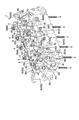
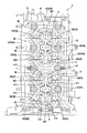
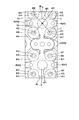
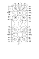
- the figure showing roughly the engine provided with the cylinder head concerning one embodiment of the present invention The perspective view which shows the cylinder head which concerns on one Embodiment of this invention from the upper left front.
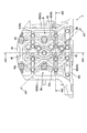
- the top view which shows the cylinder head which concerns on one Embodiment of this invention from the front.
- the top view which shows the cylinder head which concerns on one Embodiment of this invention from upper direction.
- FIG. 4 The figure which shows the cross section of the arrow A43 part of the injector support part of the cylinder head shown in FIG. 4 from an arrow direction.
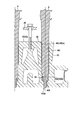
- the figure which expands and shows the injector insertion hole and positioning part of the injector support part shown in FIG. The figure which shows the cross section of the arrow A32 part of the cylinder head shown in FIG. 3 from an arrow direction.
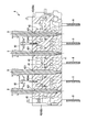
- the elements on larger scale of FIG. The figure which shows the cross section of the arrow A33 part of the cylinder head shown in FIG. 3 from an arrow direction.
- FIG. 1 is a diagram schematically showing an engine 1 including a cylinder head 4 according to the present embodiment.
- the engine 1 includes an oil pan 2, a cylinder block 3, a cylinder head 4, a rocker cover 5, a front cover 6, and a crank pulley 7.
- the crank pulley 7 side of the engine 1 is the front side (front) of the engine 1 and the opposite side is the rear side (rear).
- the gravity direction in a state where the cylinders (not shown) are arranged vertically is the lower side (downward) of the engine 1 and the opposite direction is the upper side (upper).
- the direction perpendicular to both the front-rear direction and the up-down direction is the left-right direction, and the left and right are determined from the rear to the front.
- the left-right direction corresponds to the width direction of the engine 1.
- Engine 1 is an inline 4-cylinder diesel engine. However, it is not limited to this. Each cylinder (cylinder) is arranged in the cylinder block 3 in the front-rear direction.
- FIG. 2 to 4 show the configuration of the cylinder head 4.
- FIG. 2 is a perspective view showing the cylinder head 4 from the upper left front.
- 3 is a plan view showing the cylinder head 4 from the front, and
- FIG. 4 is a plan view showing the cylinder head 4 from above.
- the cylinder head 4 is a cast product made of a metal such as an aluminum alloy, and is provided on the cylinder block 3 and has an opening at the top.
- the cylinder head 4 is fixed to the cylinder block 3 by a head bolt 8.
- a rocker cover 5 is attached to the opening of the cylinder head 4.
- the cylinder head 4 includes a bottom wall portion 41, an outer peripheral wall portion 42, and a beam portion 45 (first beam portion 43 and second beam portion 44).
- the bottom wall portion 41 is a portion constituting the lower side of the cylinder head 4 and forming a base portion (base) of the cylinder head 4.
- the bottom wall 41 is longer in the front-rear direction than in the left-right direction, and is disposed above the cylinder block 3 in the assembled state of the engine 1.
- the outer peripheral wall portion 42 is a frame-like body that stands up from the periphery of the bottom wall portion 41 and continues in the circumferential direction. As a result, a space S in which the intake / exhaust system is disposed is formed inside the outer peripheral wall portion 42.
- the outer peripheral wall portion 42 includes an outer vertical wall portion 42a and an outer horizontal wall portion 42b continuous with the outer vertical wall portion 42a.
- the outer vertical wall portions 42a are provided as a pair with a predetermined interval in the left-right direction, and extend substantially along the front-rear direction.
- the outer horizontal wall portions 42b are provided in pairs in the front-rear direction with a predetermined interval, extend substantially along the left-right direction, and are continuous with both ends of the outer vertical wall portion 42a. Since the bottom wall portion 41 is elongated in the front-rear direction, the interval between the outer vertical wall portions 42a is narrower than the interval between the outer horizontal wall portions 42b.
- the beam portion 45 includes a first beam portion 43 and a second beam portion 44.
- the first beam portion 43 is disposed between the outer vertical wall portion 42a substantially in parallel with the outer horizontal wall portion 42b, is continuous with the outer vertical wall portion 42a, and passes through the space S surrounded by the outer peripheral wall portion 42 from the vertical direction. It is divided into multiple parts. In this embodiment, the four first beam portions 43 divide the space S into five. These first beam portions 43 are arranged at substantially equal intervals in the front-rear direction.
- the first beam portion 43 is disposed so as to pass through the center (axial center) position of each combustion chamber (not shown) of the four cylinders when viewed from the vertical direction.
- bearing members 43i and 43e for rotatably supporting cam journals (not shown) of the camshafts on the intake valve side and the exhaust valve side are assembled on the upper portion of the first beam portion 43.
- a circular cam journal insertion hole 43c corresponding to the diameter of the cam journal penetrates in the front-rear direction between the upper portion of the first beam portion 43 and the bearing members 43i and 43e in a state where they are assembled.
- a semicircular concave portion is formed as viewed from the front-rear direction.
- bearing members 42i and 42e that support the cam journal are also assembled to the upper portion of the front outer lateral wall portion 42b.
- a semicircular recess is formed in each of the front and rear directions.
- the second beam portion 44 is provided between the outer horizontal wall portion 42b and substantially parallel to the outer vertical wall portion 42a, and intersects the first beam portion 43.
- the space S surrounded by the outer peripheral wall portion 42 is divided into two spaces Si and Se when viewed from the up and down direction, with the second beam portion 44 as a boundary in the left and right direction.
- the second beam portion 44 intersects with a substantially intermediate portion in the left-right direction of the first beam portion 43 and divides the space S substantially equally.
- the second beam portions 44 are bridged one by one between the two first beam portions 43 on the front side in the front-rear direction and between the two first beam portions 43 on the rear side.
- an intake system including an intake valve (not shown) is arranged in the left space Si, and an exhaust valve (not shown) is placed in the right space Se.
- the exhaust system including
- the space S is partitioned into a space Si on the intake side and a space Se on the exhaust side by the second beam portion 44, and the space Si and the space Se are subdivided by the first beam portion 43, respectively.
- the cylinder head 4 is assembled with an injector 9 for injecting fuel into the combustion chamber of the cylinder.
- injectors 9 are assembled, one for each of the four cylinders.
- the bottom wall portion 41 is provided with four injector support portions 40 that support the assembled injectors 9 according to the number of the injectors 9 (four in this embodiment).
- FIG. 5 to 7 show the configuration of the injector support section 40.
- FIG. 5, FIG. 6 and FIG. 7 are cross-sectional views of arrows A41, A42 and A43 in FIG.
- the injector support portion 40 is disposed at a portion where the first beam portion 43 and the second beam portion 44 intersect. That is, the first beam portion 43 and the second beam portion 44 are continuously integrated with the injector support portion 40 and extend toward the outer peripheral wall portion 42 (the outer vertical wall portion 42a and the outer horizontal wall portion 42b). is doing. Each crossing portion of the first beam portion 43 and the second beam portion 44 corresponds to the center (axial center) position of each combustion chamber of the four cylinders when viewed from the vertical direction. Therefore, the injector 9 is positioned corresponding to each combustion chamber of the cylinder by disposing the injector support portion 40 at the intersection.
- the injector support portion 40 is a projection portion that is raised vertically (upward) from the bottom wall portion 41, and the injector 9 is inserted into and supported by an injector insertion hole 401 formed in the projection portion.
- the injector insertion hole 401 penetrates the protrusion rising from the bottom wall 41 along the vertical direction, and also penetrates the bottom wall 41 and communicates with the combustion chamber of the cylinder.
- the injector support part 40 has a positioning part 402 for positioning the injector 9 inserted in the injector insertion hole 401 and an opening part 403 penetrating the outer peripheral part of the injector insertion hole 401.
- the injector 9 inserted into the injector insertion hole 401 and positioned by the positioning portion 402 is in a state in which the nozzle tip protrudes toward the combustion chamber of the cylinder.
- the injector 9 positioned by the positioning portion 402 is prevented from coming out of the injector insertion hole 401 in pairs by a bracket 90 bolted to the second beam portion 44.
- FIG. 8 is a view showing a cross section of the arrow A31 portion of FIG. 3 from the direction of the arrow.
- FIG. 9 shows an enlarged view of the injector insertion hole 401 and the positioning portion 402 of the injector support portion 40 shown in FIG.
- the positioning part 402 is provided in two places. These positioning portions 402 are disposed on the front side and the back side in the insertion direction of the injector 9 into the injector insertion hole 401, that is, on the upper side and the lower side in the vertical direction.
- the aspect of the positioning part 402 is not particularly limited, in the present embodiment, a part of the injector insertion hole 401 whose hole diameter is substantially the same as the outer diameter of the injector 9 is used as the positioning part 402.
- the injector insertion hole 401 is formed with three hole diameters from the upper side to the lower side.
- the first hole diameter part 401a in the upper layer part, the second hole diameter part 401b in the middle layer part, and the third hole diameter part 401c in the lower layer part are formed. Have. These are narrowed in the order of the first hole diameter portion 401a, the second hole diameter portion 401b, and the third hole diameter portion 401c.
- the first positioning portion 402a disposed on the front side (upper side) in the insertion direction of the injector 9 has a larger hole diameter than the second positioning portion 402b disposed on the back side (lower side). It is the diameter.
- the first positioning portion 402a corresponds to the upper end portion of the first hole diameter portion 401a of the injector insertion hole 401
- the second positioning portion 402b corresponds to the upper end portion of the second hole diameter portion 401b.
- the injector 9 has an insertion portion into the injector insertion hole 401 that tapers in the insertion direction, and each of the first insertion portion 9a and the second insertion portion 9b has a plurality of stages (as an example) In the injector 9 shown in FIG. 9, it is reduced in two steps).
- the first insertion part 9a is a part inserted into the first hole diameter part 401a of the injector insertion hole 401
- the second insertion part 9b is a part inserted into the second hole diameter part 401b.
- the third insertion portion (the portion inserted into the third hole diameter portion 401c) 9c of the injector 9 has a diameter smaller than the hole diameter of the third hole diameter portion 401c.
- the injector 9 in a state where the injector 9 is inserted into the injector insertion hole 401, the injector 9 includes the second insertion portion 9b while the maximum diameter portion 91 of the first insertion portion 9a contacts the upper end portion of the first hole diameter portion 401a.
- the maximum diameter portion 92 of the second electrode contacts the upper end portion of the second hole diameter portion 401b. That is, the injector 9 is in contact with the inner surface of the injector insertion hole 401 only by the first positioning portion 402a and the second positioning portion 402b. Thereby, the injector 9 is positioned and fixed at two locations, the first positioning portion 402a and the second positioning portion 402b, and the posture thereof is kept upright in the injector insertion hole 401.
- FIG. 5 shows, as an example, a configuration in which the opening 403 is disposed at a position that does not overlap with the positioning unit 402 in the insertion direction of the injector 9, that is, at a height position different from the positioning unit 402 in the vertical direction.
- the opening 403 is disposed so as to open within a range Ha from the height H2 of the second positioning portion 402b to the height H1 of the first positioning portion 402a with respect to the vertical direction. Specifically, the opening 403 opens in a range Hb from a height H3 of a valve spring seating surface 413, 414 described later to a height H1 of the first positioning portion 402a.
- the height H1 is a distance from the position of the communication port 401d of the injector insertion hole 401 to the combustion chamber to the lowest position of the first positioning portion 402a.
- the height H2 is a distance from the position of the communication port 401d to the uppermost position of the second positioning position 402b.
- the height H3 is a distance from the position of the communication port 401d to the valve spring seating surfaces 413 and 414.
- the valve spring seating surfaces 413 and 414 are formed at positions higher than the height H2 of the second positioning portion 402b and lower than the height H1 of the first positioning portion 402a (H2 ⁇ H3 ⁇ H1).
- the opening length L of the opening 403 corresponds to substantially the same or longer than the length of the valve spring (not shown) in the vertical direction.
- FIG. 10 is a view showing a cross section of the arrow A32 portion of FIG. 3 from the direction of the arrow.
- An arrow A32 portion in FIG. 3 corresponds to the height H1 of the first positioning portion 402a with respect to the vertical direction.
- 12 is a view showing a cross section of the arrow A33 portion of FIG. 3 from the direction of the arrow.
- An arrow A33 portion in FIG. 3 corresponds to slightly above the height H3 of the valve spring seating surfaces 413 and 414 with respect to the vertical direction (within the range Hb from the height H3 to the height H1).
- 11 is a partially enlarged view of FIG. 10
- FIG. 13 is a partially enlarged view of FIG.
- an intake valve insertion hole 411 is formed in the bottom wall 41 of the space Si on the intake valve side to allow the intake valve stem to communicate with the combustion chamber of the cylinder.
- an exhaust valve insertion hole 412 through which the stem of the intake valve communicates with the combustion chamber of the cylinder is formed in the bottom wall portion 41 of the space Se on the exhaust valve side.
- Concentric valve spring seating surfaces 413 and 414 are formed around the intake valve insertion hole 411 and the exhaust valve insertion hole 412 of the bottom wall portion 41, respectively.
- Stem guides 415 and 416 are assembled in the intake valve insertion hole 411 and the exhaust valve insertion hole 412, respectively.
- an intake valve insertion hole 411 communicating with the combustion chamber of the same cylinder and a valve spring seating surface around the bottom wall 41 of the space Si on the intake valve side subdivided by the first beam portion 43 are provided.
- 413 is formed in pairs with the first beam portion 43 interposed therebetween.
- an exhaust valve insertion hole 412 communicating with the combustion chamber of the same cylinder and a valve spring seating surface 414 around it are formed in the bottom wall portion 41 of the space Se on the exhaust valve side subdivided by the first beam portion 43.
- the first beam portion 43 is formed in pairs. In other words, two intake valves and two exhaust valves are arranged in pairs in the combustion chamber of one cylinder.
- the opening 403 opens toward the space Si on the intake valve side in the space S surrounded by the outer peripheral wall 42.
- the opening 403 is adjacent to the first beam 43 corresponding to the combustion chamber of one cylinder.
- These openings 403 have the same form (shape, size, arrangement height, etc.). That is, two openings 403 are formed in the injector support 40 in the direction in which the intake valve insertion holes 411 and the valve spring seating surfaces 413 of the two intake valves communicating with the combustion chambers of the same cylinder are arranged. ing.
- the injector support portion 40 has the opening 403, the intake valve insertion hole 411 and the valve spring seating surface 413 can be disposed close to the injector 9 inserted into the injector insertion hole 401.
- the outer peripheral portion of the injector insertion hole 401 is removed, and therefore, the central axis of the injector 9 (in other words, the central axis of the injector insertion hole 401) is equal to the removed thickness.
- the distance from the central axis of the intake valve insertion hole 411 (the inter-axis distance Li shown in FIG. 13) can be shortened. In this case, the inter-axis distance Li is shorter than the distance (the inter-axis distance Le shown in FIG. 13) between the central axis (axial center) of the injector 9 and the central axis of the exhaust valve insertion hole 412 (Li ⁇ Le).
- the intake valve insertion hole 411 and the valve spring seating surface 413 can be brought close to the injector 9 in this way, the intake valve stem, the valve spring, and the bearing member 43 i can also be arranged close to the injector 9.
- the intake system including the cam journal of the intake-side camshaft supported by the bearing member 43 i can be brought closer to the center of the injector 9, that is, the cylinder head 4 in the left-right direction (width direction).
- the entire width of the cylinder head 4 and hence the entire width of the engine 1 can be reduced, and the engine 1 can be reduced in size.
- the outer peripheral portion of the injector insertion hole 401 is thinned by the opening 403, the cylinder head 4 and thus the engine 1 can be reduced in weight.
- the injector insertion hole 401 is formed, for example, by subjecting a protruding portion (injector support portion 40 before processing) integrally formed when the cylinder head 4 is formed to vertical drilling.
- the positioning portion 402 first to third hole diameter portions 401a to 401c
- the opening part 403 is formed by cutting the predetermined position of the outer peripheral part.
- molding of the cylinder head 4 contains the sacrificial meat by a feeder. Therefore, a process for providing the injector support portion 40 having the injector insertion hole 401, the positioning portion 402, and the opening 403 is separately performed on the primary molded product (material) of the cylinder head 4.
- the injector 9 inserted into the injector insertion hole 401 is in a state where the outer peripheral portion is exposed in the opening 403. Therefore, there is a possibility that the lubricating oil of the camshaft on the intake valve side may enter the injector insertion hole 401 through the opening 403. For this reason, the gasket 404 is assembled to the step between the second hole diameter portion 401b and the third hole diameter portion 401c of the injector insertion hole 401. This prevents the camshaft lubricating oil from entering the combustion chamber of the cylinder.
- the opening 403 is formed in the injector support portion 40, but without penetrating the outer peripheral portion of the injector insertion hole 401, without completely removing the meat of the outer peripheral portion, You may form the thin part which left only a little.
- the intake valve insertion hole 411 and the valve spring seating surface 413 are brought closer to the injector 9 by the amount of the thickness removed from the outer peripheral portion of the injector insertion hole 401, and the inter-axis distance Li is shortened. Can be made.
- injector insertion hole 401a ... first hole diameter portion , 401b ... second hole diameter part, 401c ... third hole diameter part, 402 ... positioning part, 402a ... first positioning part, 402b ... second positioning part, 403 ... opening part, 41 ... intake valve insertion hole, 412 ... exhaust valve insertion hole, 413 ... valve spring seating surface, 414 ... valve spring seating surface, H1 ... height of the first positioning part, H2 ... height of the second positioning part, H3 ... height of valve spring seating surface, L ... opening length of opening, Le ... distance between shafts of injector and exhaust valve insertion hole, Li ... distance between shafts of injector and intake valve insertion hole, S ... outer peripheral wall Space surrounded by the parts, Se ... exhaust valve side space, Si ... intake valve side space.
Landscapes
- Engineering & Computer Science (AREA)
- Chemical & Material Sciences (AREA)
- Combustion & Propulsion (AREA)
- Mechanical Engineering (AREA)
- General Engineering & Computer Science (AREA)
- Cylinder Crankcases Of Internal Combustion Engines (AREA)
Abstract
エンジン(1)のシリンダブロック(3)側に配置される底壁部(41)と、底壁部(41)の周縁から起立する外周壁部(42)とを備える。底壁部(41)には、インジェクタ(9)を支持するインジェクタ支持部(40)が設けられている。インジェクタ支持部(40)は、インジェクタ(9)が挿入されるインジェクタ挿入孔(401)と、インジェクタ挿入孔(401)に挿入されたインジェクタ(9)を位置決めする位置決め部(402)と、位置決め部(402)を避けてインジェクタ挿入孔(401)の外周部を貫通する開口部(403)とを有している。
Description
本発明は、車両に搭載される内燃機関のシリンダヘッドに関する。
直噴式のディーゼルエンジン(以下、エンジンという)のシリンダヘッドには、燃料をシリンダの燃焼室に噴射するインジェクタ、燃焼室を開閉する吸気バルブおよび排気バルブなどが組み付けられている。例えば、特許文献1に開示されたエンジンのシリンダヘッドには、インジェクタが直立に組み付けられている。この場合、シリンダヘッドには、インジェクタ支持部(ボス)が底壁部から起立して設けられ、インジェクタは、インジェクタ支持部のインジェクタ挿入孔(ボス孔)に挿通されて支持されている。また、シリンダヘッドには、インジェクタを挟んでシリンダの配列方向と直交する方向(エンジンの幅方向)の一方に吸気バルブ、他方に排気バルブがそれぞれ燃焼室に連通して設けられている。
ところで、従来からエンジンの小型軽量化が図られている。そのための施策の一つとして、エンジンの全幅を縮小することが挙げられる。例えば、インジェクタと吸気バルブおよび排気バルブとの軸心距離を狭めれば、その分だけシリンダヘッド、ひいてはエンジンの全幅を縮小することができる。
インジェクタをインジェクタ支持部のインジェクタ挿入孔に挿入して支持する場合、インジェクタ支持部の肉厚(外内径の差)の分だけ吸気バルブおよび排気バルブをインジェクタの軸心に寄せ切れないことになる。したがって、インジェクタ支持部の肉厚がエンジン全幅の縮小を制限してしまうおそれがある。
このため、インジェクタ支持部でインジェクタを支持する場合であっても、エンジンの全幅を縮小し、小型軽量化を図ることが望まれている。
本発明のシリンダヘッドは、エンジンのシリンダブロック側に配置される底壁部と、底壁部の周縁から起立する外周壁部とを備えている。底壁部には、インジェクタを支持するインジェクタ支持部が設けられている。インジェクタ支持部は、インジェクタが挿入されるインジェクタ挿入孔と、インジェクタ挿入孔に挿入されたインジェクタを位置決めする位置決め部と、位置決め部を避けてインジェクタ挿入孔の外周部を貫通する開口部とを有している。
この場合、開口部は、インジェクタの挿入方向に対して位置決め部と重複しない位置に配置されている。
また、シリンダヘッドは、底壁部と外周壁部に加えて、梁部を備えている。梁部は、インジェクタ支持部と連続し、外周壁部で囲まれたスペースを吸気バルブ側と排気バルブ側に区画するとともに、区画された吸気バルブ側のスペースと排気バルブ側のスペースをそれぞれ細分している。かかるシリンダヘッドにおいて、開口部は、吸気バルブ側のスペースに向けて開口している。
例えば、開口部は、梁部で細分されて隣り合う吸気バルブ側のスペースに向けて1つずつ開口させる。
なお、位置決め部は、インジェクタの挿入方向の手前側と奥側に離間して配置されている。例えば、位置決め部は、インジェクタ挿入孔のうち、孔径がインジェクタの外径と略同一の部位とすればよい。この場合、手前側の位置決め部は、奥側の位置決め部よりも孔径が大径とすることができる。
本発明のシリンダヘッドによれば、エンジンの全幅を縮小し、小型軽量化を図ることができる。
以下、本発明の一実施形態に係るシリンダヘッドについて、図1から図13を参照して説明する。図1は、本実施形態のシリンダヘッド4を備えるエンジン1を概略的に示す図である。エンジン1は、オイルパン2と、シリンダブロック3と、シリンダヘッド4と、ロッカカバー5と、フロントカバー6と、クランクプーリ7とを備えている。以下、エンジン1のクランクプーリ7側をエンジン1の前側(前方)、その反対側を後側(後方)とする。また、シリンダ(図示省略)を鉛直に配置した状態における重力方向をエンジン1の下側(下方)、その反対方向を上側(上方)とする。そして、前後方向および上下方向といずれも直交する方向を左右方向とし、左右は後方から前方へ向かって定める。左右方向は、エンジン1の幅方向に相当する。
エンジン1は、直列4気筒のディーゼルエンジンである。ただし、これに限定されるものではない。各気筒(シリンダ)は、シリンダブロック3に前後方向へ配列されている。
図2から図4には、シリンダヘッド4の構成を示す。図2は、シリンダヘッド4を左上前方から示す斜視図である。図3は前方、図4は上方からそれぞれシリンダヘッド4を示す平面図である。
シリンダヘッド4は、アルミ合金などの金属からなる鋳造品であり、シリンダブロック3の上に設けられ、上部に開口を有している。シリンダヘッド4は、ヘッドボルト8によってシリンダブロック3に固定されている。シリンダヘッド4の開口には、ロッカカバー5が取り付けられる。
シリンダヘッド4は、底壁部41と、外周壁部42と、梁部45(第1の梁部43および第2の梁部44)とを備えている。
底壁部41は、シリンダヘッド4における下側を構成し、シリンダヘッド4の基部(ベース)をなす部分である。底壁部41は、左右方向に比べて前後方向が長手となっており、エンジン1の組立状態においてはシリンダブロック3の上方側に配置される。
外周壁部42は、底壁部41の周縁から起立し、周方向に連続する枠状体である。これにより、外周壁部42の内側に吸排気系が配置されるスペースSが形成される。外周壁部42は、外縦壁部42aと、外縦壁部42aと連続する外横壁部42bとを含んで構成されている。外縦壁部42aは、左右方向に所定間隔をあけて対をなして設けられ、前後方向に略沿って延在している。外横壁部42bは、前後方向に所定間隔をあけて対をなして設けられ、左右方向に略沿って延在して外縦壁部42aの両端に連続している。底壁部41は、前後方向に長手となっているため、外縦壁部42a同士の間隔は、外横壁部42b同士の間隔よりも狭い。
梁部45は、第1の梁部43と第2の梁部44を含んで構成されている。第1の梁部43は、外横壁部42bと略平行に外縦壁部42aの間に配置されて外縦壁部42aと連続し、外周壁部42で囲まれたスペースSを上下方向から見て複数に区画している。本実施形態では、4つの第1の梁部43により、スペースSが5つに区画されている。これらの第1の梁部43は、前後方向に略等間隔で配置されている。第1の梁部43は、上下方向から見て4つのシリンダの各燃焼室(図示省略)の中心(軸心)位置を通るように配置されている。
また、第1の梁部43の上部には、吸気バルブ側および排気バルブ側のカムシャフトのカムジャーナル(図示省略)を回転自在に支持する軸受部材43i,43eが組み付けられている。第1の梁部43の上部と軸受部材43i,43eには、これらが組み付けられた状態でカムジャーナルの径寸法に対応する円形のカムジャーナル挿通孔43cが互いの間で前後方向に貫通するように、前後方向から見て半円形状の凹部がそれぞれ形成されている。同様に、前側の外横壁部42bの上部にも、カムジャーナルを支持する軸受部材42i,42eが組み付けられている。外横壁部42bの上部と軸受部材42i,42eには、これらが組み付けられた状態でカムジャーナルの径寸法に対応する円形のカムジャーナル挿通孔42cが互いの間で前後方向に貫通するように、前後方向から見て半円形状の凹部がそれぞれ形成されている。
第2の梁部44は、外縦壁部42aと略平行に外横壁部42bの間に設けられ、第1の梁部43と交差している。外周壁部42で囲まれたスペースSは、第2の梁部44を左右方向の境界として、上下方向から見て2つのスペースSi,Seに区画される。本実施形態では、第2の梁部44は、第1の梁部43の左右方向の略中間部位と交差しており、スペースSを略等分している。この場合、第2の梁部44は、前後方向の前側の2つの第1の梁部43の間、および後側の2つの第1の梁部43の間にそれぞれ1つずつ架け渡されている。第2の梁部44によって区画された2つのスペースSi,Seのうち、左側のスペースSiには吸気バルブ(図示省略)を含む吸気系が配置され、右側のスペースSeには排気バルブ(図示省略)を含む排気系が配置されている。
すなわち、スペースSは、第2の梁部44によって吸気側のスペースSiと排気側のスペースSeに区画され、スペースSiおよびスペースSeは、第1の梁部43によってそれぞれ細分されている。
シリンダヘッド4には、燃料をシリンダの燃焼室に噴射するインジェクタ9が組み付けられている。本実施形態では、4つのシリンダに1つずつ、4つのインジェクタ9が組み付けられている。底壁部41には、組み付けられるインジェクタ9を支持するインジェクタ支持部40がインジェクタ9の本数に応じて(本実施形態では4つ)設けられている。
図5から図7には、インジェクタ支持部40の構成を示す。図5、図6および図7は、図4の矢印A41、A42、およびA43部分の断面を各矢印方向から示す図である。
インジェクタ支持部40は、第1の梁部43と第2の梁部44が交差する部位に配置されている。すなわち、第1の梁部43と第2の梁部44は、インジェクタ支持部40と連続して一体化され、外周壁部42(外縦壁部42aおよび外横壁部42b)へ向けて延在している。第1の梁部43と第2の梁部44の各交差部位は、上下方向から見て4つのシリンダの各燃焼室の中心(軸心)位置にそれぞれ対応している。したがって、インジェクタ支持部40をかかる交差部位に配置することで、インジェクタ9がシリンダの各燃焼室に対応して位置付けられるようになっている。
インジェクタ支持部40は、底壁部41から鉛直(上方)に立ち上げられた突起部であり、該突起部に形成されたインジェクタ挿入孔401にインジェクタ9を挿入し、これを支持している。インジェクタ挿入孔401は、底壁部41から立ち上がる突起部を上下方向に沿って貫通するとともに、底壁部41も貫通してシリンダの燃焼室と連通している。
インジェクタ支持部40は、インジェクタ挿入孔401に挿入されたインジェクタ9を位置決めする位置決め部402と、インジェクタ挿入孔401の外周部を貫通する開口部403とを有している。インジェクタ挿入孔401に挿入され、位置決め部402で位置決めされたインジェクタ9は、ノズル先端がシリンダの燃焼室に向けて突出した状態となる。位置決め部402で位置決めされたインジェクタ9は、図8に示すように、第2の梁部44にボルト止めされたブラケット90により、2本一組でインジェクタ挿入孔401からの抜け止めが図られている。図8は、図3の矢印A31部分の断面を矢印方向から示す図である。
図9には、図8に示すインジェクタ支持部40のインジェクタ挿入孔401と位置決め部402を拡大して示す。図9に示すように、位置決め部402は、2箇所に設けられている。これらの位置決め部402は、インジェクタ挿入孔401へのインジェクタ9の挿入方向の手前側と奥側に、つまり上下方向の上側と下側に離間して配置されている。位置決め部402の態様は特に限定されないが、本実施形態では、インジェクタ挿入孔401のうち、孔径がインジェクタ9の外径と略同一の部位を位置決め部402としている。
インジェクタ挿入孔401は、上側から下側へ3つの孔径で形成されており、上層部の第1の孔径部401a、中層部の第2の孔径部401b、下層部の第3の孔径部401cを有している。これらは、第1の孔径部401a、第2の孔径部401b、第3の孔径部401cの順に孔径が狭められている。
位置決め部402のうち、インジェクタ9の挿入方向の手前側(上側)に配置される第1の位置決め部402aは、奥側(下側)に配置される第2の位置決め部402bよりも孔径が大径とされている。第1の位置決め部402aは、インジェクタ挿入孔401の第1の孔径部401aの上端部、第2の位置決め部402bは、第2の孔径部401bの上端部にそれぞれ相当している。
なお、インジェクタ9は、インジェクタ挿入孔401への挿入部位が挿入方向に向かって先細り形状となっており、第1の挿入部位9aおよび第2の挿入部位9bの径寸法がそれぞれ複数段階(一例として、図9に示すインジェクタ9では2段階)で縮小されている。第1の挿入部位9aは、インジェクタ挿入孔401の第1の孔径部401aへ挿入される部位、第2の挿入部位9bは、第2の孔径部401bへ挿入される部位である。インジェクタ9の第3の挿入部位(第3の孔径部401cへ挿入される部位)9cは、径寸法が第3の孔径部401cの孔径よりも小さくなっている。
このため、インジェクタ挿入孔401へ挿入された状態において、インジェクタ9は、第1の挿入部位9aの最大径部分91が第1の孔径部401aの上端部と接触するとともに、第2の挿入部位9bの最大径部分92が第2の孔径部401bの上端部と接触する。すなわち、インジェクタ9は、第1の位置決め部402aと第2の位置決め部402bのみでインジェクタ挿入孔401の内面と接触する。これにより、インジェクタ9は、第1の位置決め部402aと第2の位置決め部402bの2箇所で位置決め固定され、インジェクタ挿入孔401内でその姿勢が直立に保たれる。
開口部403は、位置決め部402を避けるように形成されている。このため、インジェクタ支持部40に開口部403を形成しても、位置決め部402でのインジェクタ9の位置決めは妨げられることがない。図5には、インジェクタ9の挿入方向に対して位置決め部402と重複しない位置、つまり上下方向に対して位置決め部402と異なる高さ位置で開口部403を配置した構成を一例として示す。
本実施形態では、上下方向に対する第2の位置決め部402bの高さH2から第1の位置決め部402aの高さH1までの範囲内Haに開口するように、開口部403が配置されている。具体的には、後述するバルブスプリング着座面413,414の高さH3から第1の位置決め部402aの高さH1までの範囲内Hbで、開口部403が開口している。高さH1は、インジェクタ挿入孔401の燃焼室との連通口401dの位置から第1の位置決め部402aの最下部位置までの距離である。高さH2は、連通口401dの位置から第2の位置決め位置402bの最上部位置までの距離である。高さH3は、連通口401dの位置からバルブスプリング着座面413,414までの距離である。バルブスプリング着座面413,414は、第2の位置決め部402bの高さH2よりも高く、第1の位置決め部402aの高さH1よりも低い位置に形成されている(H2<H3<H1)。この場合、開口部403の開口長さLは、バルブスプリング(図示省略)の上下方向の長さと略同一もしくはそれ以上に相当する。
図5、および図10から図13には、インジェクタ挿入孔401、位置決め部402、および開口部403の配置関係を示す。図10は、図3の矢印A32部分の断面を矢印方向から示す図である。図3の矢印A32部分は、上下方向に対する第1の位置決め部402aの高さH1に相当する。図12は、図3の矢印A33部分の断面を矢印方向から示す図である。図3の矢印A33部分は、上下方向に対するバルブスプリング着座面413,414の高さH3よりもわずかに上方(高さH3から高さH1までの範囲内Hb)に相当する。図11は図10、図13は図12のそれぞれ部分拡大図である。
図10から図13に示すように、吸気バルブ側のスペースSiの底壁部41には、吸気バルブのステムをシリンダの燃焼室に連通させる吸気バルブ挿通孔411が形成されている。一方、排気バルブ側のスペースSeの底壁部41には、吸気バルブのステムをシリンダの燃焼室に連通させる排気バルブ挿通孔412が形成されている。また、底壁部41の吸気バルブ挿通孔411および排気バルブ挿通孔412の周りには、同心円状のバルブスプリング着座面413,414がそれぞれ形成されている。吸気バルブ挿通孔411および排気バルブ挿通孔412には、ステムガイド415,416がそれぞれ組み付けられている。
この場合、第1の梁部43で細分化された吸気バルブ側のスペースSiの底壁部41には、同一シリンダの燃焼室に連通する吸気バルブ挿通孔411、およびその周りにバルブスプリング着座面413が第1の梁部43を挟んで対をなして形成されている。一方、第1の梁部43で細分化された排気バルブ側のスペースSeの底壁部41には、同一シリンダの燃焼室に連通する排気バルブ挿通孔412およびその周りのバルブスプリング着座面414が、第1の梁部43を挟んで対をなして形成されている。すなわち、1つのシリンダの燃焼室には、吸気バルブと排気バルブがそれぞれ2つ一組で配置される。
図12および図13に示すように、開口部403は、外周壁部42で囲まれたスペースSのうち、吸気バルブ側のスペースSiに向けて開口している。本実施形態では、1つのシリンダの燃焼室に吸気バルブが2つずつ配置されているため、開口部403は、1つのシリンダの燃焼室に対応する第1の梁部43を挟んで隣り合う吸気バルブ側の2つのスペースSiに向けてそれぞれ1つずつ開口している。これらの開口部403は、同一形態(形状や大きさ、配置高さなど)とする。すなわち、同一シリンダの燃焼室に連通する2つの吸気バルブの吸気バルブ挿通孔411およびバルブスプリング着座面413がそれぞれ配置されている方向へ向けて、2つの開口部403がインジェクタ支持部40に形成されている。
インジェクタ支持部40が開口部403を有することで、吸気バルブ挿通孔411およびバルブスプリング着座面413を、インジェクタ挿入孔401に挿入されたインジェクタ9に近づけて配置することができる。開口部403においては、インジェクタ挿入孔401の外周部の肉が除かれているため、取り除かれた肉厚の分だけ、インジェクタ9の中心軸(換言すれば、インジェクタ挿入孔401の中心軸)と吸気バルブ挿通孔411の中心軸との距離(図13に示す軸間距離Li)を短縮させることができる。この場合、軸間距離Liは、インジェクタ9の中心軸(軸心)と排気バルブ挿通孔412の中心軸との距離(図13に示す軸間距離Le)よりも短い(Li<Le)。
このように吸気バルブ挿通孔411およびバルブスプリング着座面413をインジェクタ9に近づけることができるので、吸気バルブのステムやバルブスプリング、さらには軸受部材43iもインジェクタ9に近づけて配置することができる。これにより、軸受部材43iで支持される吸気側のカムシャフトのカムジャーナルを含む吸気系をインジェクタ9、すなわちシリンダヘッド4の左右方向(幅方向)の中央に寄せることができる。
したがって、シリンダヘッド4の全幅、ひいてはエンジン1の全幅を縮小させることができ、エンジン1の小型化を図ることができる。また、開口部403によりインジェクタ挿入孔401の外周部が除肉されるため、その分だけシリンダヘッド4、ひいてはエンジン1を軽量化することができる。
なお、インジェクタ挿入孔401は、例えば、シリンダヘッド4の成形時に一体的に形成された突起部(加工前のインジェクタ支持部40)に、上下方向の穿孔加工を施すことで形成される。その際、インジェクタ挿入孔401の孔径を段階的に拡大させることで、位置決め部402(第1から第3の孔径部401a~401c)が形成される。そして、インジェクタ挿入孔401を形成した後、その外周部の所定位置を切削加工することで、開口部403が形成される。これにより、インジェクタ挿入孔401、位置決め部402、および開口部403を有するインジェクタ支持部40をシリンダヘッド4に設けることができる。シリンダヘッド4の成形時に一体的に形成される突起部は、押湯による駄肉を含んでいる。したがって、インジェクタ挿入孔401、位置決め部402、および開口部403を有するインジェクタ支持部40を設けるための加工をシリンダヘッド4の一次成形品(素材)に対して別途行う。
また、図5および図9に示すように、インジェクタ挿入孔401に挿入されたインジェクタ9は、その外周部が開口部403において露呈された状態となる。したがって、吸気バルブ側のカムシャフトの潤滑オイルが開口部403を通ってインジェクタ挿入孔401に浸入するおそれがある。このため、インジェクタ挿入孔401の第2の孔径部401bと第3の孔径部401cとの段差にガスケット404が組み付けられている。これにより、シリンダの燃焼室内へのカムシャフトの潤滑オイルの混入を防いでいる。
以上、本発明の実施形態を説明したが、上述した実施形態は、一例として提示したものであり、発明の範囲を限定することは意図していない。このような新規な実施形態は、その他の様々な形態で実施されることが可能であり、発明の要旨を逸脱しない範囲で、種々の省略、置き換え、変更を行うことができる。これら実施形態やその変形は、発明の範囲や要旨に含まれるとともに、特許請求の範囲に記載された発明とその均等の範囲に含まれる。
例えば、上述した実施形態において、インジェクタ支持部40には、開口部403を形成しているが、インジェクタ挿入孔401の外周部を貫通することなく、該外周部の肉を完全に除くことなく、少しだけ残した薄肉部を形成してもよい。この場合にも、かかる薄肉部においては、インジェクタ挿入孔401の外周部から除いた肉厚の分だけ、吸気バルブ挿通孔411およびバルブスプリング着座面413をインジェクタ9に近づけ、軸間距離Liを短縮させることができる。
1…エンジン、2…オイルパン、3…シリンダブロック、4…シリンダヘッド、5…ロッカカバー、6…フロントカバー、7…クランクプーリ、8…ヘッドボルト、9…インジェクタ、9a…インジェクタの第1の挿入部位、9b…インジェクタの第2の挿入部位、9c…インジェクタの第3の挿入部位、40…インジェクタ支持部、41…底壁部、42…外周壁部、42a…外縦壁部、42b…外横壁部、43…第1の梁部、43c…カムジャーナル挿通孔、43e…軸受部材、43i…軸受部材、44…第2の梁部、401…インジェクタ挿入孔、401a…第1の孔径部、401b…第2の孔径部、401c…第3の孔径部、402…位置決め部、402a…第1の位置決め部、402b…第2の位置決め部、403…開口部、411…吸気バルブ挿通孔、412…排気バルブ挿通孔、413…バルブスプリング着座面、414…バルブスプリング着座面、H1…第1の位置決め部の高さ、H2…第2の位置決め部の高さ、H3…バルブスプリング着座面の高さ、L…開口部の開口長さ、Le…インジェクタと排気バルブ挿通孔との軸間距離、Li…インジェクタと吸気バルブ挿通孔との軸間距離、S…外周壁部で囲まれたスペース、Se…排気バルブ側スペース、Si…吸気バルブ側スペース。
Claims (8)
- エンジンのシリンダブロック側に配置される底壁部と、
前記底壁部の周縁から起立する外周壁部と、を備え、
前記底壁部には、インジェクタを支持するインジェクタ支持部が設けられ、
前記インジェクタ支持部は、
インジェクタが挿入されるインジェクタ挿入孔と、
前記インジェクタ挿入孔に挿入されたインジェクタを位置決めする位置決め部と、
前記位置決め部を避けて前記インジェクタ挿入孔の外周部を貫通する開口部と、を有する
シリンダヘッド。 - 前記開口部は、前記インジェクタの挿入方向に対して前記位置決め部と重複しない位置に配置されている
請求項1に記載のシリンダヘッド。 - 前記インジェクタ支持部と連続し、前記外周壁部で囲まれたスペースを吸気バルブ側と排気バルブ側に区画するとともに、区画された吸気バルブ側のスペースと排気バルブ側のスペースをそれぞれ細分する梁部を備え、
前記開口部は、前記吸気バルブ側のスペースに向けて開口している
請求項1に記載のシリンダヘッド。 - 前記インジェクタ支持部と連続し、前記外周壁部で囲まれたスペースを吸気バルブ側と排気バルブ側に区画するとともに、区画された吸気バルブ側のスペースと排気バルブ側のスペースをそれぞれ細分する梁部を備え、
前記開口部は、前記吸気バルブ側のスペースに向けて開口している
請求項2に記載のシリンダヘッド。 - 前記開口部は、前記梁部で細分されて隣り合う前記吸気バルブ側のスペースに向けて1つずつ開口している
請求項3に記載のシリンダヘッド。 - 前記開口部は、前記梁部で細分されて隣り合う前記吸気バルブ側のスペースに向けて1つずつ開口している
請求項4に記載のシリンダヘッド。 - 前記位置決め部は、前記インジェクタの挿入方向の手前側と奥側に離間して配置されている
請求項1から6のいずれかに記載のシリンダヘッド。 - 前記位置決め部は、前記インジェクタ挿入孔のうち、孔径が前記インジェクタの外径と略同一の部位であり、
前記手前側の位置決め部は、前記奥側の位置決め部よりも前記孔径が大径である
請求項7に記載のシリンダヘッド。
Applications Claiming Priority (2)
| Application Number | Priority Date | Filing Date | Title |
|---|---|---|---|
| JP2015255074A JP6651844B2 (ja) | 2015-12-25 | 2015-12-25 | シリンダヘッド |
| JP2015-255074 | 2015-12-25 |
Publications (1)
| Publication Number | Publication Date |
|---|---|
| WO2017110932A1 true WO2017110932A1 (ja) | 2017-06-29 |
Family
ID=59089542
Family Applications (1)
| Application Number | Title | Priority Date | Filing Date |
|---|---|---|---|
| PCT/JP2016/088221 Ceased WO2017110932A1 (ja) | 2015-12-25 | 2016-12-21 | シリンダヘッド |
Country Status (2)
| Country | Link |
|---|---|
| JP (1) | JP6651844B2 (ja) |
| WO (1) | WO2017110932A1 (ja) |
Citations (5)
| Publication number | Priority date | Publication date | Assignee | Title |
|---|---|---|---|---|
| US5711266A (en) * | 1995-12-21 | 1998-01-27 | Mercedes-Benz Ag | Cylinder head for an internal combustion engine |
| JP2001336464A (ja) * | 2000-05-25 | 2001-12-07 | Denso Corp | 内燃機関およびインジェクタ情報読み取り装置 |
| JP2003269245A (ja) * | 2002-03-14 | 2003-09-25 | Honda Motor Co Ltd | 燃料噴射弁を備える内燃機関 |
| JP2007187105A (ja) * | 2006-01-13 | 2007-07-26 | Mazda Motor Corp | 直噴ディーゼルエンジンのシリンダヘッド構造 |
| JP2009215921A (ja) * | 2008-03-07 | 2009-09-24 | Honda Motor Co Ltd | 内燃機関の燃料噴射弁取付け構造 |
-
2015
- 2015-12-25 JP JP2015255074A patent/JP6651844B2/ja not_active Expired - Fee Related
-
2016
- 2016-12-21 WO PCT/JP2016/088221 patent/WO2017110932A1/ja not_active Ceased
Patent Citations (5)
| Publication number | Priority date | Publication date | Assignee | Title |
|---|---|---|---|---|
| US5711266A (en) * | 1995-12-21 | 1998-01-27 | Mercedes-Benz Ag | Cylinder head for an internal combustion engine |
| JP2001336464A (ja) * | 2000-05-25 | 2001-12-07 | Denso Corp | 内燃機関およびインジェクタ情報読み取り装置 |
| JP2003269245A (ja) * | 2002-03-14 | 2003-09-25 | Honda Motor Co Ltd | 燃料噴射弁を備える内燃機関 |
| JP2007187105A (ja) * | 2006-01-13 | 2007-07-26 | Mazda Motor Corp | 直噴ディーゼルエンジンのシリンダヘッド構造 |
| JP2009215921A (ja) * | 2008-03-07 | 2009-09-24 | Honda Motor Co Ltd | 内燃機関の燃料噴射弁取付け構造 |
Also Published As
| Publication number | Publication date |
|---|---|
| JP6651844B2 (ja) | 2020-02-19 |
| JP2017115822A (ja) | 2017-06-29 |
Similar Documents
| Publication | Publication Date | Title |
|---|---|---|
| CN205101056U (zh) | 凸轮轴轴承盖及汽车 | |
| JP6651844B2 (ja) | シリンダヘッド | |
| JP2011080384A (ja) | 車両用エンジン | |
| JP5626485B2 (ja) | 内燃機関の鋳物部品,ベアリングキャップ及びその製造方法 | |
| US8667944B2 (en) | Cylinder head assembly having an oil routing plug | |
| JP2007120506A5 (ja) | ||
| JP2007120506A (ja) | 多気筒エンジン | |
| JP5498426B2 (ja) | 内燃機関の気液分離室構造 | |
| JP2011140904A (ja) | 車両用エンジン | |
| JP6354792B2 (ja) | 内燃機関用ピストン | |
| US10215061B2 (en) | Internal combustion engine | |
| JP5436530B2 (ja) | ロッカーシャフトの回り止め構造 | |
| JP2009002219A (ja) | V型ohvエンジン | |
| JP5492174B2 (ja) | クランクシャフト構造 | |
| JP4073737B2 (ja) | 多気筒エンジンのクランク室間連通構造 | |
| JP2017089470A (ja) | 内燃機関のシリンダヘッド構造及び内燃機関 | |
| JP2005291089A (ja) | エンジンのシリンダブロック | |
| JP6390656B2 (ja) | 多気筒エンジン用カムシャフトおよびその製造方法 | |
| JP6653053B2 (ja) | シリンダブロック | |
| JP2015068206A (ja) | 内燃機関 | |
| JP4627304B2 (ja) | シリンダヘッドおよびこれを備える内燃機関 | |
| CN208153174U (zh) | 汽缸缸体和内燃发动机 | |
| JP7135817B2 (ja) | シリンダヘッド | |
| JP3962269B2 (ja) | 多気筒エンジン | |
| JP6780659B2 (ja) | シリンダヘッド |
Legal Events
| Date | Code | Title | Description |
|---|---|---|---|
| 121 | Ep: the epo has been informed by wipo that ep was designated in this application |
Ref document number: 16878819 Country of ref document: EP Kind code of ref document: A1 |
|
| NENP | Non-entry into the national phase |
Ref country code: DE |
|
| 122 | Ep: pct application non-entry in european phase |
Ref document number: 16878819 Country of ref document: EP Kind code of ref document: A1 |