WO2017110748A1 - 鉄道車両の車体 - Google Patents
鉄道車両の車体 Download PDFInfo
- Publication number
- WO2017110748A1 WO2017110748A1 PCT/JP2016/087813 JP2016087813W WO2017110748A1 WO 2017110748 A1 WO2017110748 A1 WO 2017110748A1 JP 2016087813 W JP2016087813 W JP 2016087813W WO 2017110748 A1 WO2017110748 A1 WO 2017110748A1
- Authority
- WO
- WIPO (PCT)
- Prior art keywords
- internal space
- sound absorbing
- outer plate
- hole
- region
- Prior art date
- Legal status (The legal status is an assumption and is not a legal conclusion. Google has not performed a legal analysis and makes no representation as to the accuracy of the status listed.)
- Ceased
Links
Images


Classifications
-
- B—PERFORMING OPERATIONS; TRANSPORTING
- B61—RAILWAYS
- B61D—BODY DETAILS OR KINDS OF RAILWAY VEHICLES
- B61D17/00—Construction details of vehicle bodies
- B61D17/04—Construction details of vehicle bodies with bodies of metal; with composite, e.g. metal and wood body structures
- B61D17/08—Sides
-
- B—PERFORMING OPERATIONS; TRANSPORTING
- B61—RAILWAYS
- B61D—BODY DETAILS OR KINDS OF RAILWAY VEHICLES
- B61D17/00—Construction details of vehicle bodies
- B61D17/04—Construction details of vehicle bodies with bodies of metal; with composite, e.g. metal and wood body structures
- B61D17/12—Roofs
-
- B—PERFORMING OPERATIONS; TRANSPORTING
- B61—RAILWAYS
- B61D—BODY DETAILS OR KINDS OF RAILWAY VEHICLES
- B61D17/00—Construction details of vehicle bodies
- B61D17/04—Construction details of vehicle bodies with bodies of metal; with composite, e.g. metal and wood body structures
- B61D17/18—Internal lining, e.g. insulating
- B61D17/185—Internal lining, e.g. insulating for sound insulating
-
- B—PERFORMING OPERATIONS; TRANSPORTING
- B61—RAILWAYS
- B61D—BODY DETAILS OR KINDS OF RAILWAY VEHICLES
- B61D49/00—Other details
-
- B—PERFORMING OPERATIONS; TRANSPORTING
- B61—RAILWAYS
- B61F—RAIL VEHICLE SUSPENSIONS, e.g. UNDERFRAMES, BOGIES OR ARRANGEMENTS OF WHEEL AXLES; RAIL VEHICLES FOR USE ON TRACKS OF DIFFERENT WIDTH; PREVENTING DERAILING OF RAIL VEHICLES; WHEEL GUARDS, OBSTRUCTION REMOVERS OR THE LIKE FOR RAIL VEHICLES
- B61F1/00—Underframes
Definitions
- the present invention relates to a vehicle body of a railway vehicle.
- Patent Literature 1 discloses a sound absorbing panel that covers an underfloor device under a vehicle body from below and from the side. According to this, the noise which reflects between the ground wall surface (for example, soundproof wall surface or tunnel wall surface) of the track and the vehicle can be absorbed by the sound absorbing panel.
- the speed is further increased, and the noise is approximately proportional to the square of the vehicle traveling speed or more, so further noise countermeasures may be desired.
- the sound absorbing panel is provided not only around the underfloor equipment under the vehicle body but also on the side surface of the vehicle body, a large sound absorbing area can be secured.
- the side structure must be positioned inward in the vehicle width direction by the thickness of the sound absorbing panel, and the cabin space of the vehicle body is narrow. Problem arises. Further, since the work of joining the sound absorbing panel to the outer surface of the side structure is required, the number of vehicle assembly steps increases and the number of parts of the vehicle also increases.
- an object of the present invention is to make it possible to satisfactorily absorb the noise of a railway vehicle without reducing the cabin space of the vehicle body and preventing the increase in the number of parts and the number of vehicle assembly steps.
- a vehicle body of a railway vehicle is a vehicle body of a railway vehicle including a frame, a side structure, and a roof structure, and at least one of the frame, the side structure, and the roof structure is: An outer plate that faces the outside of the vehicle, and a reinforcing portion that is connected to the inner surface of the outer plate and that forms at least one internal space between the outer plate and the outer plate. Is formed with at least one sound absorption hole communicating with the internal space.
- the sound absorbing function is given to the vehicle body itself, sound absorption on the vehicle body side can be performed without installing a sound absorbing panel on the outer surface of the outer plate portion of the vehicle body. Therefore, it is possible to satisfactorily absorb the noise of the railway vehicle without reducing the cabin space of the vehicle body and preventing an increase in the number of parts and the number of vehicle assembly steps.
- the present invention it is possible to satisfactorily absorb the noise of the railway vehicle without reducing the cabin space of the vehicle body and preventing the increase in the number of parts and the number of vehicle assembly steps.
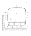
- FIG. 1 is a cross-sectional view of the railway vehicle 1 according to the first embodiment viewed from the longitudinal direction of the vehicle.
- the railway vehicle 1 includes a vehicle body 2 having a cabin space P therein and a carriage 3 that supports the vehicle body 2.
- the vehicle body 2 includes a frame 4, a side structure 5 in which a window opening 5 a is formed and extending upward from an end in the vehicle width direction of the frame 4, and a roof structure 6 connected to the upper end of the side structure 5.
- Each of the underframe 4, the side structure 5, and the roof structure 6 is a double skin structure having a cross section of a truss structure, and is formed by extrusion using a light metal (for example, an aluminum alloy).
- the side structure 5 includes an outer plate portion 7 facing the outside of the vehicle and a reinforcing portion 10 connected to the inner side surface of the outer plate portion 7 and forming a plurality of internal spaces S with the outer plate portion 7.
- the end of the internal space S in the longitudinal direction of the vehicle body is closed by a lid (for example, a wife structure) (not shown).
- the reinforcing portion 10 includes an inner plate portion 8 disposed with a gap from the outer plate portion 7 to the inside of the vehicle, and an outer plate portion 7 and a plurality of connecting rib portions 9 connected to the inner plate portion 8.
- the plurality of connecting rib portions 9 together with the outer plate portion 7 and the inner plate portion 8 form a plurality of triangles in a truss shape.
- the underframe 4 and the roof structure 6 also have the same structure as the side structure 5.
- a plurality of underfloor devices 11 (for example, inverters, transformers, etc.) attached to the underframe 4 are arranged below the vehicle body 2.
- a rail 14 on which the carriage 3 travels is laid on the ground 13, and a soundproof wall 15 protrudes upward from the ground 13.
- the soundproof wall 15 is disposed on the side of the railway vehicle 1 and protrudes to a position higher than the underframe 4 and lower than the window opening 5a.
- FIG. 2 is a cross-sectional perspective view of the upper portion of the waist plate region 5b of the side structure 5 shown in FIG. 3 is a cross-sectional perspective view of the lower portion of the waist plate region 5b of the side structure 5 shown in FIG.
- an internal space S having a triangular cross section with the inner surface of the outer plate portion 7 as the bottom.
- the first internal space S1, the second internal space S2, the third internal space S3, the third internal space S4,... The eleventh internal space S11.
- a twelfth internal space S12 and a thirteenth internal space S13 are provided.
- a plurality of first sound absorption holes H ⁇ b> 1 communicating with the first internal space S ⁇ b> 1 are formed in the first region R ⁇ b> 1 facing the first internal space S ⁇ b> 1 in the outer plate part 7.
- a plurality of second sound absorbing holes H2 communicating with the second internal space S2 are formed in the second region R2 facing the second internal space S2 in the outer plate portion 7.
- a plurality of third sound absorbing holes H3 communicating with the third internal space S3 are formed in the third region R3 facing the third internal space S3 in the outer plate portion 7.
- a plurality of fourth sound absorbing holes H4 communicating with the fourth internal space S4 are formed in the fourth region R4 facing the fourth internal space S4 in the outer plate portion 7.
- a plurality of eleventh sound absorbing holes H11 communicating with the eleventh internal space S11 are formed in the eleventh region R11 facing the eleventh internal space S11 in the outer plate portion 7.
- a plurality of twelfth sound absorbing holes H12 communicating with the twelfth internal space S12 are formed in the twelfth region R12 facing the twelfth internal space S12 of the outer plate portion 7.
- a sound absorbing hole communicating with the thirteenth internal space S13 is not formed in the thirteenth region R13 facing the lowermost thirteenth internal space S13 in the outer plate portion 7.
- Each of the sound absorbing holes H1 to H12 is, for example, a circular hole.
- the first sound absorbing hole H1 and the second sound absorbing hole H2 have the same hole diameter and hole length (length in the axial direction of the hole), but the arrangement (ie, hole distribution shape) and The aperture ratios are different from each other.
- the arrangement of the first sound absorption holes H1 is an aspect in which the first sound absorption holes H1 are arranged in a row in the longitudinal direction of the vehicle body.
- the arrangement of the second sound absorption holes H2 is such that the second sound absorption holes H2 are arranged in two rows in the longitudinal direction of the vehicle body, and the second sound absorption holes H2 in the upper row and the second sound absorption holes H2 in the lower row are arranged in the vehicle longitudinal direction. Is a mode in which they deviate from each other.
- the opening ratio of the first sound absorbing hole H1 is smaller than the opening ratio of the second sound absorbing hole H2.
- the second sound absorbing hole H2 and the third sound absorbing hole H3 have the same hole length, hole pitch (that is, distance between holes) and arrangement, but have different hole diameters. Specifically, the hole diameter of the third sound absorbing hole H3 is larger than the hole diameter of the second sound absorbing hole H2.
- the third sound absorbing hole H3 and the fourth sound absorbing hole H4 have the same hole diameter, hole length, aperture ratio, and arrangement.
- the aperture ratio of the first region R1 of the outer plate portion 7 is smaller than the aperture ratio of the second region R2 of the outer plate portion 7, and the aperture ratio of the second region R2 of the outer plate portion 7 is the second aperture ratio of the outer plate portion 7. It is smaller than the aperture ratio of the three regions R3.
- an aperture ratio means the ratio of the opening area of all the sound absorption holes per area of an outer plate part.
- the aperture ratio of the lowermost thirteenth region R13 of the outer plate portion 7 is zero.
- the eleventh sound absorbing hole H11 and the twelfth sound absorbing hole H12 have the same hole diameter, hole length, and hole pitch, but are different in arrangement (ie, hole distribution shape). Specifically, the arrangement of the eleventh sound absorbing holes H11 is such that the eleventh sound absorbing holes H11 are arranged in two rows in the longitudinal direction of the vehicle body, and the eleventh sound absorbing holes H11 in the upper row and the eleventh sound absorbing holes H11 in the lower row are arranged. The vehicle body longitudinal direction positions are shifted from each other.
- the arrangement of the twelfth sound absorbing holes H12 is such that the twelfth sound absorbing holes H12 are arranged in a line in the longitudinal direction of the vehicle body.
- the opening ratio of the thirteenth region R13 of the outer plate portion 7 is smaller than the opening ratio of the twelfth region R12 of the outer plate portion 7, and the opening ratio of the twelfth region R12 of the outer plate portion 7 is the same as that of the outer plate portion 7. 11
- the aperture ratio of the region R11 is smaller. In the present embodiment, among the regions R11 to R13 of the outer plate portion 7, the region closer to the base frame 4 has a higher generated stress and a lower strength reduction tolerance. Therefore, the aperture ratios of the regions R11 to R13 of the outer plate portion 7 are set to be smaller as the region is closer to the frame 4.
- a drain hole D communicating with the lower ends of the first to twelfth internal spaces S1 to S12 is formed. That is, the ends of the first to twelfth internal spaces S1 to S12 in the longitudinal direction of the vehicle are closed by a lid (not shown), but the first to twelfth sound absorbing holes H1 to H12 to the first to twelfth internal spaces S1 to S12 Even if water enters S12, it is drained naturally from the drain hole D.
- the drain hole D also functions as a sound absorbing hole.
- the sound absorbing material A may be inserted into at least one of the first to thirteenth internal spaces S1 to S13.
- Various types of sound absorbing material A can be used.
- a porous material or the like is used.
- the sound absorbing material A may be inserted into all of the internal spaces where the sound absorbing holes communicate with each other, or may be selectively inserted into one or more internal spaces selected from the internal spaces.
- the sound absorbing material A may not be inserted into the internal space corresponding to the area where the aperture ratio is less than a predetermined value, and the sound absorbing material A may be inserted into the internal space corresponding to the area where the aperture ratio is equal to or greater than the predetermined value.
- the sound absorbing function is given to the side structure 5 itself, sound absorption on the vehicle body 2 side can be performed without attaching a sound absorbing panel to the outer surface of the side structure 5. Therefore, it is possible to satisfactorily absorb the noise of the railway vehicle 1 without reducing the cabin space P of the vehicle body 2 and preventing an increase in the number of parts and the number of vehicle assembly steps. That is, even if the sound insulation is impaired by forming the holes H1 to H12 in the side structure 5, the noise outside the vehicle body 2 is reduced by the sound absorption holes H1 to H12, so The total amount of noise entering the car can be reduced.
- the sound absorption holes H1 to H12 are disposed above the frame 4 and below the window opening 5a, the noise reflected between the soundproof wall 15 and the vehicle body 2 can be effectively absorbed. . Further, since the sound absorption holes H1 to H12 include those having different hole diameters, hole lengths, aperture ratios, or arrangements, it is possible to perform a sound absorption design suitable for noise characteristics.
- the aperture ratios of the regions R11 to R13 of the outer plate part 7 are set so as to be smaller as the region is closer to the frame 4, and the aperture ratios of the regions R1 to R3 of the outer plate part 7 are set. Is set to be smaller in the region closer to the window opening 5a. That is, paying attention to the fact that the side structure 5 includes both a portion having a high required strength and a portion having a low required strength, by providing sound absorbing holes H1 to H12 at appropriate positions on the outer plate portion 7, 5 strength maintenance and improvement in sound absorption performance can be achieved.
- FIG. 4 is a cross-sectional perspective view of the upper part of the waist plate region 25b of the side structure 25 of the railway vehicle according to the second embodiment.
- a waist plate region 25b between the underframe and the window opening 25a in the side structure 25 includes an outer plate portion 27 facing the outside of the vehicle, and a reinforcing portion 28 joined to the outer plate portion 27 by welding. And have.
- the outer plate portion 27 and the reinforcing portion 28 are formed of, for example, a stainless plate.
- the reinforcing portion 28 is connected to the inner side surface of the outer plate portion 27 and forms an internal space T with the outer plate portion 27.
- the reinforcing portion 28 is a horizontal bone member that includes a head portion 29, a pair of leg portions 30, and a pair of flange portions 31, and extends in the longitudinal direction of the vehicle body.
- the head 29 is spaced apart from the outer plate 27 to the inside of the vehicle and extends in the longitudinal direction of the vehicle body.
- the pair of leg portions 30 extend from both ends (that is, the upper end and the lower end) of the head portion 29 toward the outer plate portion 27.
- the pair of flange portions 31 extend in opposite directions (that is, upward and downward) from the end portions of the pair of leg portions 30 on the outer plate portion 27 side.
- the pair of flange portions 31 are joined to the outer plate portion 27 by laser welding or spot welding. That is, the internal space T is surrounded by the outer plate portion 27, the pair of leg portions 30, and the head portion 29.
- the end of the internal space T in the longitudinal direction of the vehicle body is closed by a lid (for example, a wife structure) (not shown).
- a plurality of internal spaces T having a square cross section are provided side by side in the vertical direction. That is, in the waist plate region 25b of the side structure 25, a first internal space T1, a second internal space T2,.
- a first internal space T1 In the waist plate region 25b of the side structure 25, a plurality of first sound absorbing holes H21 communicating with the first internal space T1 are formed.
- a plurality of second sound absorbing holes H22 communicating with the second internal space T2 are formed in the second region Q2 facing the second internal space T2 in the outer plate part 7.
- the first sound absorbing holes H21 and the second sound absorbing holes H22 are arranged in a row in the longitudinal direction of the vehicle body, but the hole diameter and the hole pitch are different from each other. Specifically, the hole diameter of the first sound absorbing hole H21 is smaller than the hole diameter of the second sound absorbing hole H22, and the hole pitch of the first sound absorbing hole H21 is larger than the hole pitch of the second sound absorbing hole H22. Further, the sound absorbing material A may be inserted into at least one of the internal spaces T1, T2. Similarly to the first embodiment, the sound absorbing material A may be inserted into all of the internal spaces, or may be selectively inserted into one or more internal spaces selected from the internal spaces.
- Table 1 shows the specifications of the side structure of Example 1.
- the side structure of Example 1 has a double skin structure as in the first embodiment, but the specifications are different from the examples shown in FIGS.
- region corresponds to the first to twelfth regions R 1 to R 12 of the side structure 5.
- the “creepage length” is the length in the height direction along the outer surface of each region.
- space cross-sectional area corresponds to the cross-sectional area of the internal spaces S1 to S12 having a triangular cross section.
- the “plate thickness” corresponds to the thickness of the outer plate portion 7 of the side structure 5 and is the same as the hole length.
- hole diameter corresponds to the hole diameter of the sound absorbing hole formed in the outer plate portion 7.
- Opening ratio means the ratio of the opening area of all sound absorbing holes per area of the outer plate.
- the “resonance frequency” is calculated by Equation 1.
- S means a spatial sectional area
- L means a creepage length
- R means an aperture ratio
- t means a plate thickness
- ⁇ means a hole diameter.
- FIG. 5 is a graph showing the relationship between the sound absorption per unit length of the side structure and the 1/3 octave band center frequency in Example 1.
- the sound absorbing holes are arranged in a line in the longitudinal direction of the vehicle.
- a line L in the graph of FIG. 5 indicates a value obtained by adding up the sound absorption forces of all the sound absorption holes in the first to thirteenth regions.
- Each line other than the line L in the graph of FIG. 5 has shown the value of the sound absorption force by the sound absorption hole of each area
- the sound absorbing power of the individual regions differed in each region because the values of the aperture ratio of the sound absorbing holes and the space cross-sectional area differed from each other. And by combining the sound absorbing power in each region, a sufficient sound absorbing power was exhibited as a whole, and the frequency band of the absorbed noise was expanded.
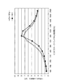
- FIG. 6 is a graph showing the sound absorbing power per vehicle in Examples 1 and 2.
- the square-plotted line (non-uniformity) in the graph of FIG. 6 corresponds to Example 1, and included those in which the hole diameter and the aperture ratio differ from one region to another.
- the triangle plotted line (uniform) in the graph of FIG. 6 is Example 2, and the frequency calculated by Formula 1 for each region is substantially the same.
- the frequency band of the noise absorbed per vehicle is expanded, while the hole diameter and the aperture ratio are made the same between each area. By doing so, the peak value of the sound absorbing power per vehicle was increased.
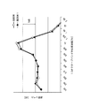
- FIG. 7 is a graph showing the in-vehicle noise level when traveling through the tunnel in Example 1 and the comparative example.
- the comparative example in FIG. 7 is measured with a vehicle having no sound absorbing holes in the side structure.
- the noise outside the vehicle is reduced by the sound absorption holes even if the sound insulation is impaired by the sound absorption holes of the side structure, so the total amount of noise entering the vehicle from the outside of the vehicle is smaller than in the comparative example. Reduced.
- the present invention is not limited to the above-described embodiments, and the configuration can be changed, added, or deleted.
- the above embodiments may be arbitrarily combined with each other. For example, some configurations or methods in one embodiment may be applied to other embodiments. In addition, a part of the configuration in the embodiment can be arbitrarily extracted separately from the other configurations in the embodiment.
- the sound absorbing hole is provided in the region between the frame and the window opening in the side structure, the sound absorbing hole may be provided also in the region above the window opening in the side structure. In addition to the side structure or instead of the side structure, sound absorption holes may be provided in the frame and / or the roof structure.
- the internal space in which the sound absorbing holes of the side structure communicate with each other is not limited to those in the above embodiments.
- it may be an internal space of a side structure having a double skin structure and an internal space having a square cross section.
- the shape of the sound absorbing hole is not particularly limited, and may be an oval shape, an elliptical shape, a quadrangular shape, a polygonal shape, or the like other than the circular shape.
Landscapes
- Engineering & Computer Science (AREA)
- Mechanical Engineering (AREA)
- Life Sciences & Earth Sciences (AREA)
- Wood Science & Technology (AREA)
- Transportation (AREA)
- Soundproofing, Sound Blocking, And Sound Damping (AREA)
- Body Structure For Vehicles (AREA)
- Vehicle Interior And Exterior Ornaments, Soundproofing, And Insulation (AREA)
Abstract
台枠と、側構体と、屋根構体とを備えた鉄道車両の車体において、前記台枠、前記側構体及び前記屋根構体の少なくとも1つは、車外に面する外板部と、前記外板部の内側面に接続されて且つ前記外板部との間で少なくとも1つの内部空間を形成する補強部と、を有し、前記外板部には、前記内部空間に連通する少なくとも1つの吸音孔が形成されている。
Description
本発明は、鉄道車両の車体に関する。
高速鉄道車両では、種々の騒音対策を施すことにより、騒音レベルが所定の環境規制値を下回るようにしている。例えば、特許文献1には、車体下の床下機器を下方及び側方から覆う吸音パネルが開示されている。これによれば、線路脇の地上壁面(例えば、防音壁面やトンネル壁面)と車両との間で反射し合う騒音を吸音パネルによって吸収することができる。
ところで、近年の鉄道車両では更なる高速化が進んでおり、騒音は車両走行速度の二乗以上に略比例するため、更なる騒音対策が望まれる場合がある。例えば、吸音パネルを車体下の床下機器の周囲だけでなく車体側面にも設ければ、吸音面積を大きく確保することできる。しかし、車体の側構体の側面に吸音パネルを設置してしまうと、車両限界の観点から、吸音パネルの厚み分だけ側構体を車幅方向内側に位置させねばならず、車体の客室空間が狭くなる問題が生じる。また、側構体の外面に吸音パネルを接合する作業が必要になることで、車両組立工数が増大するとともに、車両の部品点数も増大することになる。
そこで本発明は、車体の客室空間を狭小化させず、かつ、部品点数及び車両組立工数の増加を防止しながら、鉄道車両の騒音を良好に吸音できるようにすることを目的とする。
本発明の一態様に係る鉄道車両の車体は、台枠と、側構体と、屋根構体とを備えた鉄道車両の車体において、前記台枠、前記側構体及び前記屋根構体の少なくとも1つは、車外に面する外板部と、前記外板部の内側面に接続されて且つ前記外板部との間で少なくとも1つの内部空間を形成する補強部と、を有し、前記外板部には、前記内部空間に連通する少なくとも1つの吸音孔が形成されている。
前記構成によれば、車体自体に吸音機能が付与されるため、車体の外板部の外面に吸音パネルを設置することなく、車体側での吸音を行うことができる。よって、車体の客室空間を狭小化させずに、かつ、部品点数及び車両組立工数の増加を防止しながら、鉄道車両の騒音を良好に吸音することができる。
本発明によれば、車体の客室空間を狭小化させず、かつ、部品点数及び車両組立工数の増加を防止しながら、鉄道車両の騒音を良好に吸音することができる。
以下、図面を参照して実施形態を説明する。
(第1実施形態)
図1は、第1実施形態に係る鉄道車両1の車両長手方向から見た断面図である。図1に示すように、鉄道車両1は、内部に客室空間Pを有する車体2と、車体2を支持する台車3とを備える。車体2は、台枠4と、窓開口5aが形成され且つ台枠4の車幅方向端部から上方に延びる側構体5と、側構体5の上端部に接続された屋根構体6とを備える。台枠4、側構体5及び屋根構体6の各々は、トラス構造の断面を有するダブルスキン構体であり、軽金属(例えば、アルミニウム合金)を用いて押出成形されてなる。
図1は、第1実施形態に係る鉄道車両1の車両長手方向から見た断面図である。図1に示すように、鉄道車両1は、内部に客室空間Pを有する車体2と、車体2を支持する台車3とを備える。車体2は、台枠4と、窓開口5aが形成され且つ台枠4の車幅方向端部から上方に延びる側構体5と、側構体5の上端部に接続された屋根構体6とを備える。台枠4、側構体5及び屋根構体6の各々は、トラス構造の断面を有するダブルスキン構体であり、軽金属(例えば、アルミニウム合金)を用いて押出成形されてなる。
側構体5は、車外に面する外板部7と、外板部7の内側面に接続されて且つ外板部7との間で複数の内部空間Sを形成する補強部10とを有する。内部空間Sの車体長手方向の端部は、図示しない蓋(例えば、妻構体)で閉塞されている。補強部10は、外板部7から車内側に隙間をあけて配置された内板部8と、外板部7及び内板部8に連結された複数の連結リブ部9とを含む。複数の連結リブ部9は、外板部7及び内板部8とともにトラス状に複数の三角形を形成している。なお、台枠4及び屋根構体6も、側構体5と同様の構造を有する。
車体2の下方には、台枠4に取り付けられた複数の床下機器11(例えば、インバータや変圧器等)が配置されている。地面13には、台車3が走行するレール14が敷設され、地面13からは防音壁15が上方に突出している。防音壁15は、鉄道車両1の側方に配置され、台枠4よりも高く且つ窓開口5aよりも低い位置まで突出している。
図2は、図1に示す側構体5の腰板領域5bのうち上側部分の断面斜視図である。図3は、図1に示す側構体5の腰板領域5bのうち下側部分の断面斜視図である。図2及び3に示すように、側構体5のうち台枠4と窓開口5aとの間の腰板領域5bの内部には、外板部7の内面を底辺とする断面三角形状の内部空間Sが鉛直方向に並んで複数(本実施形態では13個)設けられている。即ち、側構体5の下側領域5bには、上から順に、第1内部空間S1、第2内部空間S2、第3内部空間S3、第3内部空間S4、・・・、第11内部空間S11、第12内部空間S12、及び、第13内部空間S13が設けられている。
図2に示すように、外板部7のうち第1内部空間S1に面する第1領域R1には、第1内部空間S1に連通する複数の第1吸音孔H1が形成されている。外板部7のうち第2内部空間S2に面する第2領域R2には、第2内部空間S2に連通する複数の第2吸音孔H2が形成されている。外板部7のうち第3内部空間S3に面する第3領域R3には、第3内部空間S3に連通する複数の第3吸音孔H3が形成されている。外板部7のうち第4内部空間S4に面する第4領域R4には、第4内部空間S4に連通する複数の第4吸音孔H4が形成されている。
図3に示すように、外板部7のうち第11内部空間S11に面する第11領域R11には、第11内部空間S11に連通する複数の第11吸音孔H11が形成されている。外板部7のうち第12内部空間S12に面する第12領域R12には、第12内部空間S12に連通する複数の第12吸音孔H12が形成されている。外板部7のうち最下の第13内部空間S13に面する第13領域R13には、第13内部空間S13に連通する吸音孔は形成されていない。各吸音孔H1~H12は、例えば、円孔である。
図2に示すように、第1吸音孔H1と第2吸音孔H2とは、孔径及び孔長(孔の軸線方向の長さ)が互いに同じであるが、配置(即ち、孔分布形状)及び開口率が互いに異なっている。具体的には、第1吸音孔H1の配置は、第1吸音孔H1が車体長手方向に向けて一列に並んだ態様である。第2吸音孔H2の配置は、第2吸音孔H2が車体長手方向に向けて二列に並び、かつ、上列の第2吸音孔H2と下列の第2吸音孔H2との車体長手方向位置が互いにずれた態様である。第1吸音孔H1の開口率は、第2吸音孔H2の開口率よりも小さい。
第2吸音孔H2と第3吸音孔H3とは、孔長、孔ピッチ(即ち、孔間距離)及び配置が互いに同じであるが、孔径が互いに異なっている。具体的には、第3吸音孔H3の孔径は、第2吸音孔H2の孔径よりも大きい。第3吸音孔H3と第4吸音孔H4とは、孔径、孔長、開口率及び配置が互いに同じである。外板部7の第1領域R1の開口率は、外板部7の第2領域R2の開口率よりも小さく、外板部7の第2領域R2の開口率は、外板部7の第3領域R3の開口率よりも小さい。本実施形態では、外板部7の各領域R1~R3のうち窓開口5aに近い領域ほど発生応力が高く、強度低下許容度が小さくなる。よって、外板部7の各領域R1~R3の各開口率は、窓開口5aに近い領域ほど小さくなるように設定されている。なお、開口率は、外板部の面積あたりの全吸音孔の開口面積の割合を意味する。
図3に示すように、外板部7のうち最下の第13領域R13の開口率は、ゼロである。第11吸音孔H11と第12吸音孔H12とは、孔径、孔長及び孔ピッチが互いに同じであるが、配置(即ち、孔分布形状)が互いに異なっている。具体的には、第11吸音孔H11の配置は、第11吸音孔H11が車体長手方向に向けて二列に並び、かつ、上列の第11吸音孔H11と下列の第11吸音孔H11との車体長手方向位置が互いにずれた態様である。第12吸音孔H12の配置は、第12吸音孔H12が車体長手方向に向けて一列に並んだ態様である。外板部7の第13領域R13の開口率は、外板部7の第12領域R12の開口率よりも小さく、外板部7の第12領域R12の開口率は、外板部7の第11領域R11の開口率よりも小さい。本実施形態では、外板部7の各領域R11~R13のうち台枠4に近い領域ほど発生応力が高く、強度低下許容度が小さくなる。よって、外板部7の各領域R11~R13の各開口率は、台枠4に近い領域ほど小さくなるように設定されている。
外板部7の第1~第12領域R1~R12には、第1~第12内部空間S1~S12の下端部に連通するドレイン孔Dが形成されている。即ち、第1~第12内部空間S1~S12の車両長手方向の端部は図示しない蓋で閉塞されているが、第1~第12吸音孔H1~H12から第1~第12内部空間S1~S12に水が浸入しても、ドレイン孔Dから自然と排水される。なお、ドレイン孔Dも、吸音孔として機能する。
第1~第13内部空間S1~S13の少なくとも1つには、吸音材Aが挿入されていてもよい。吸音材Aには、様々な種類のものが利用可能であるが、例えば、多孔質材等が用いられる。吸音材Aは、各吸音孔が夫々連通する各内部空間の全てに挿入されてもよいが、各内部空間から選ばれた1以上の内部空間に選択的に挿入されてもよい。例えば、開口率が所定値未満の領域に対応する内部空間には吸音材Aを挿入せず、開口率が所定値以上の領域に対応する内部空間に吸音材Aを挿入してもよい。
以上に説明した構成によれば、側構体5自体に吸音機能が付与されるため、側構体5の外面に吸音パネルを貼り付けることなく、車体2側での吸音を行うことができる。よって、車体2の客室空間Pを狭小化させずに、かつ、部品点数及び車両組立工数の増加を防止しながら、鉄道車両1の騒音を良好に吸音することができる。即ち、側構体5に孔H1~H12を形成することで遮音性が損なわれたとしても、車体2の外部の騒音が吸音孔H1~H12により低減されることで、車体2全体を介して車外から車内に入る騒音総量を抑えることができる。
また、吸音孔H1~H12は、台枠4よりも上方で且つ窓開口5aよりも下方に配置されているので、防音壁15と車体2との間で反射し合う騒音を効果的に吸音できる。また、吸音孔H1~H12は、孔径、孔長、開口率又は配置の少なくとも1つが互いに異なるものを含むので、騒音の特性に合わせて好適な吸音設計を行うことができる。
また、外板部7の各領域R11~R13の各開口率は、台枠4に近い領域ほど小さくなるように設定されており、かつ、外板部7の各領域R1~R3の各開口率は、窓開口5aに近い領域ほど小さくなるように設定されている。即ち、側構体5には、要求強度が高い部分と要求強度が低い部分との両方が存在することに着目して、外板部7の適所に吸音孔H1~H12を設けることで、側構体5の強度維持と吸音性能の向上とを両立させることができる。
(第2実施形態)
図4は、第2実施形態に係る鉄道車両の側構体25の腰板領域25bのうち上側部分の断面斜視図である。図4に示すように、側構体25のうち台枠と窓開口25aとの間の腰板領域25bは、車外に面する外板部27と、外板部27に溶接により接合された補強部28とを有する。外板部27及び補強部28は、例えば、ステンレス板により形成されている。補強部28は、外板部27の内側面に接続されて且つ外板部27との間で内部空間Tを形成している。補強部28は、頭部29と、一対の脚部30と、一対のフランジ部31とを有し、車体長手方向に延びた横骨部材である。
図4は、第2実施形態に係る鉄道車両の側構体25の腰板領域25bのうち上側部分の断面斜視図である。図4に示すように、側構体25のうち台枠と窓開口25aとの間の腰板領域25bは、車外に面する外板部27と、外板部27に溶接により接合された補強部28とを有する。外板部27及び補強部28は、例えば、ステンレス板により形成されている。補強部28は、外板部27の内側面に接続されて且つ外板部27との間で内部空間Tを形成している。補強部28は、頭部29と、一対の脚部30と、一対のフランジ部31とを有し、車体長手方向に延びた横骨部材である。
頭部29は、外板部27から車内側に離間して車体長手方向に延びている。一対の脚部30は、頭部29の両端(即ち、上端及び下端)から外板部27に向けて延びている。一対のフランジ部31は、一対の脚部30の外板部27側の端部から互いに反対方向(即ち、上方及び下方)に延びている。一対のフランジ部31は、外板部27に対してレーザー溶接又はスポット溶接により接合されている。即ち、内部空間Tは、外板部27と一対の脚部30と頭部29とにより囲まれている。内部空間Tの車体長手方向の端部は、図示しない蓋(例えば、妻構体)により閉塞されている。
側構体25の腰板領域25bには、断面四角形状の複数の内部空間Tが鉛直方向に並んで設けられている。即ち、側構体25の腰板領域25bには、上から順に、第1内部空間T1、第2内部空間T2・・・が設けられている。外板部27のうち第1内部空間T1に面する第1領域Q1には、第1内部空間T1に連通する複数の第1吸音孔H21が形成されている。外板部7のうち第2内部空間T2に面する第2領域Q2には、第2内部空間T2に連通する複数の第2吸音孔H22が形成されている。
第1吸音孔H21と第2吸音孔H22とは、それぞれ車体長手方向に向けて一列に配置されているが、孔径及び孔ピッチが互いに異なっている。具体的には、第1吸音孔H21の孔径は、第2吸音孔H22の孔径よりも小さく、第1吸音孔H21の孔ピッチは、第2吸音孔H22の孔ピッチよりも大きい。また、各内部空間T1,T2のうち少なくとも1つには、吸音材Aが挿入されていてもよい。吸音材Aは、第1実施形態と同様に、各内部空間の全てに挿入されてもよいが、各内部空間から選ばれた1以上の内部空間に選択的に挿入されてもよい。
以上に説明した構成によれば、車体の客室空間を狭小化させずに、かつ、部品点数及び車両組立工数の増加を防止しながら、鉄道車両の騒音を効果的に吸音することができる。また、騒音の特性に合わせて好適な吸音設計を行うことができる。また、側構体25の強度維持と吸音性能の向上とを両立させることができる。なお、他の構成は前述した第1実施形態と同様であるため説明を省略する。また、第2実施形態では、外板部の吸音孔が連通した内部空間を形成する補強部として、横骨部材を例示したが、縦骨部材を用いてもよい。
(実施例/比較例)
次に、実施例及び比較例について説明する。
次に、実施例及び比較例について説明する。
表1は、実施例1の側構体の諸元を示す。実施例1の側構体は、第1実施形態と同様にダブルスキン構造であるが、図2及び3に示した例とは諸元が異なる。表1において、「領域」は、側構体5の第1~第12領域R1~R12に相当する。「沿面長」は、各領域の外面に沿った高さ方向の長さである。「空間断面積」は、断面三角形状の内部空間S1~S12の断面積に相当する。「板厚」は、側構体5の外板部7の肉厚に相当し、孔長と同一である。「孔径」は、外板部7に形成された吸音孔の孔径に相当する。「開口率」は、外板部の面積あたりの全吸音孔の開口面積の割合を意味する。「共鳴周波数」は、数式1で算出される。なお、数式1において、Sは空間断面積を意味し、Lは沿面長を意味し、Rは開口率を意味し、tは板厚を意味し、φは孔径を意味する。


図5は、実施例1における側構体の単位長さあたりの吸音力と1/3オクターブバンド中心周波数との関係を示すグラフである。なお、各領域では、吸音孔を車両長手方向に一列に配置した。図5のグラフ中の線Lは、第1~第13領域の全ての吸音孔による吸音力を合算した値を示している。図5のグラフ中の線L以外の各線は、個々の領域の吸音孔による吸音力の値を示している。このグラフから分かるように、個々の領域では、吸音孔の開口率や空間断面積等の値が互いに異なることで、個々の領域の吸音力も異なった。そして、個々の領域での吸音力が合わさることで、全体として十分な吸音力が発揮され、かつ、吸音される騒音の周波数帯が拡げられた。
図6は、実施例1及び2における1両あたりの吸音力を示すグラフである。図6のグラフ中の四角プロットされた線(不均一)は、実施例1に相当し、各領域間で孔径及び開口率が互いに異なるものを含めた。図6のグラフ中の三角プロットされた線(均一)は、実施例2であり、各領域ごとに数式1で計算される周波数がほぼ同一となるようにしたものである。このグラフから分かるように、各領域間で孔径及び開口率を互いに異ならせることにより、1両あたりで吸音される騒音の周波数帯が拡げられる一方、各領域間で孔径及び開口率を互いに同一とすることにより、1両あたりの吸音力のピーク値が高められた。
図7は、実施例1及び比較例におけるトンネル走行時の車内騒音レベルを示すグラフである。図7中の比較例は、側構体に吸音孔が存在しない車両で測定されたものである。図7から分かるように、実施例1では、側構体の吸音孔により遮音性が損なわれても、車外の騒音が吸音孔により低減されるので、車外から車内に入る騒音総量が比較例に比べて低減された。
なお、本発明は前述した各実施形態に限定されるものではなく、その構成を変更、追加、又は削除することができる。前記各実施形態は互いに任意に組み合わせてもよく、例えば1つの実施形態中の一部の構成又は方法を他の実施形態に適用してもよい。また、実施形態中の一部の構成は、その実施形態中の他の構成から分離して任意に抽出可能である。また、側構体のうち台枠と窓開口との間の領域に吸音孔を設けたが、側構体のうち窓開口より上側の領域にも吸音孔を設けてもよい。また、側構体に加え又は側構体に代えて、台枠及び/又は屋根構体に吸音孔を設けてもよい。また、側構体の吸音孔が連通する内部空間は、前記各実施形態のものに限られない。例えば、ダブルスキン構造の側構体の内部空間であって断面四角形状の内部空間でもよい。また、吸音孔の形状は、特に限定されず、円形状以外にも、長円形状、楕円形状、四角形状、多角形状等でもよい。
1 鉄道車両
2 車体
3 台車
4 台枠
5,25 側構体
5a 窓開口
5b 下側領域
6 屋根構体
7,27 外板部
8 内板部
9 連結リブ部
10,28 補強部
25 側構体
25b 腰板領域
29 頭部
30 脚部
31 フランジ部
D ドレイン孔
H1~H12 第1~第12吸音孔
R1~R13 第1~第13領域
Q1~Q13 第1~第13領域
S,T 内部空間
S1~S4,S11~S13 第1~第4内部空間,第11~第13内部空間
T1,T2 第1,第2内部空間
2 車体
3 台車
4 台枠
5,25 側構体
5a 窓開口
5b 下側領域
6 屋根構体
7,27 外板部
8 内板部
9 連結リブ部
10,28 補強部
25 側構体
25b 腰板領域
29 頭部
30 脚部
31 フランジ部
D ドレイン孔
H1~H12 第1~第12吸音孔
R1~R13 第1~第13領域
Q1~Q13 第1~第13領域
S,T 内部空間
S1~S4,S11~S13 第1~第4内部空間,第11~第13内部空間
T1,T2 第1,第2内部空間
Claims (12)
- 台枠と、側構体と、屋根構体とを備えた鉄道車両の車体において、
前記台枠、前記側構体及び前記屋根構体の少なくとも1つは、車外に面する外板部と、前記外板部の内側面に接続されて且つ前記外板部との間で少なくとも1つの内部空間を形成する補強部と、を有し、
前記外板部には、前記内部空間に連通する少なくとも1つの吸音孔が形成されている、鉄道車両の車体。 - 前記吸音孔は、前記側構体に形成され、かつ、前記台枠よりも上方で且つ前記側構体の窓開口よりも下方に配置されている、請求項1に記載の鉄道車両の車体。
- 前記少なくとも1つの吸音孔は、複数の吸音孔である、請求項1又は2に記載の鉄道車両の車体。
- 前記少なくとも1つの内部空間は、第1内部空間及び第2内部空間を含み、
前記少なくとも1つの吸音孔は、前記第1内部空間に連通する少なくとも1つの第1吸音孔と、前記第2内部空間に連通する少なくとも1つの第2吸音孔と、を含み、
前記第1吸音孔と前記第2吸音孔とは、孔径、開口率、孔長又は配置の少なくとも1つが互いに異なっている、請求項1乃至3のいずれか1項に記載の鉄道車両の車体。 - 前記外板部のうち前記第1内部空間に面する第1領域は、前記外板部のうち前記第2内部空間に面する第2領域よりも発生応力が高く、
前記第1領域の開口率は、前記第2領域の開口率よりも小さい、請求項4に記載の鉄道車両の車体。 - 前記吸音孔は、前記側構体に形成され、
前記第1内部空間は、前記第2内部空間よりも前記台枠の近くに配置され、
前記外板部のうち前記第1内部空間に面する第1領域の開口率は、前記外板部のうち前記第2内部空間に面する第2領域の開口率よりも小さい、請求項4に記載の鉄道車両の車体。 - 前記吸音孔は、前記側構体に形成され、
前記第1内部空間は、前記第2内部空間よりも前記側構体の窓開口の近くに配置され、
前記外板部のうち前記第1内部空間に面する第1領域の開口率は、前記外板部のうち前記第2内部空間に面する第2領域の開口率よりも小さい、請求項4に記載の鉄道車両の車体。 - 前記少なくとも1つの吸音孔は、前記内部空間の下端に連通するドレイン孔を含む、請求項1乃至7のいずれか1項に記載の鉄道車両の車体。
- 前記補強部は、前記外板部から車内側に隙間をあけて配置された内板部と、前記外板部及び前記内板部に連結された複数の連結リブ部とを含む、請求項1乃至8のいずれか1項に記載の鉄道車両の車体。
- 前記複数の連結リブ部は、前記外板部及び前記内板部とともにトラス状に複数の三角形を形成している、請求項9に記載の鉄道車両の車体。
- 前記補強部は、頭部と、前記頭部の両端から前記外板部に向けて延びる一対の脚部と、前記一対の脚部から互いに反対方向に延びて前記外板部に接合された一対のフランジ部とを含む、請求項1乃至8のいずれか1項に記載の鉄道車両の車体。
- 前記少なくとも1つの内部空間には、吸音材が挿入されている、請求項1乃至11のいずれか1項に記載の鉄道車両の車体。
Priority Applications (2)
| Application Number | Priority Date | Filing Date | Title |
|---|---|---|---|
| CN201680075012.8A CN108367758B (zh) | 2015-12-22 | 2016-12-19 | 铁道车辆的车身 |
| US16/065,169 US10843714B2 (en) | 2015-12-22 | 2016-12-19 | Carbody of railcar |
Applications Claiming Priority (2)
| Application Number | Priority Date | Filing Date | Title |
|---|---|---|---|
| JP2015249665A JP6748425B2 (ja) | 2015-12-22 | 2015-12-22 | 鉄道車両の車体 |
| JP2015-249665 | 2015-12-22 |
Publications (1)
| Publication Number | Publication Date |
|---|---|
| WO2017110748A1 true WO2017110748A1 (ja) | 2017-06-29 |
Family
ID=59090401
Family Applications (1)
| Application Number | Title | Priority Date | Filing Date |
|---|---|---|---|
| PCT/JP2016/087813 Ceased WO2017110748A1 (ja) | 2015-12-22 | 2016-12-19 | 鉄道車両の車体 |
Country Status (4)
| Country | Link |
|---|---|
| US (1) | US10843714B2 (ja) |
| JP (1) | JP6748425B2 (ja) |
| CN (1) | CN108367758B (ja) |
| WO (1) | WO2017110748A1 (ja) |
Families Citing this family (5)
| Publication number | Priority date | Publication date | Assignee | Title |
|---|---|---|---|---|
| JP6748425B2 (ja) * | 2015-12-22 | 2020-09-02 | 川崎重工業株式会社 | 鉄道車両の車体 |
| JP6944324B2 (ja) * | 2017-09-26 | 2021-10-06 | 川崎重工業株式会社 | 鉄道車両構体 |
| CN109606401A (zh) * | 2018-10-26 | 2019-04-12 | 安徽鑫铂铝业股份有限公司 | 一种高强韧轨道交通车体铝型材 |
| JP6801145B1 (ja) * | 2019-02-20 | 2020-12-16 | 株式会社日立製作所 | 軌条車両 |
| JP7337223B1 (ja) * | 2022-05-11 | 2023-09-01 | レノボ・シンガポール・プライベート・リミテッド | 防振部材及び電子機器 |
Citations (7)
| Publication number | Priority date | Publication date | Assignee | Title |
|---|---|---|---|---|
| JPH04118356A (ja) * | 1990-09-07 | 1992-04-20 | Hitachi Ltd | 低騒音車両 |
| JPH04147199A (ja) * | 1990-10-09 | 1992-05-20 | Nitto Boseki Co Ltd | 吸音体 |
| JPH06156276A (ja) * | 1992-11-18 | 1994-06-03 | Hitachi Ltd | 車両用防音装置 |
| JP2003081131A (ja) * | 2001-09-14 | 2003-03-19 | Kobe Steel Ltd | 防音表面部材 |
| JP2004042735A (ja) * | 2002-07-10 | 2004-02-12 | Kawasaki Heavy Ind Ltd | 車両用スカート体 |
| JP2006256398A (ja) * | 2005-03-16 | 2006-09-28 | Hitachi Ltd | 鉄道車両及び吸音材の製造方法 |
| WO2006106854A1 (ja) * | 2005-03-30 | 2006-10-12 | Matsushita Electric Industrial Co., Ltd. | 吸音構造体 |
Family Cites Families (17)
| Publication number | Priority date | Publication date | Assignee | Title |
|---|---|---|---|---|
| US6378252B1 (en) * | 2000-09-19 | 2002-04-30 | Solutions Jupiter Inc. | Stud for retaining insulating panels and method for installing insulating panels along a wall provided with such studs |
| JP3558610B2 (ja) * | 2001-06-26 | 2004-08-25 | 富士ゼロックスエンジニアリング株式会社 | 古紙の処理装置 |
| JP2006123614A (ja) * | 2004-10-27 | 2006-05-18 | Hitachi Ltd | 遮音材を有する鉄道車両,遮音材、および遮音材の製造方法 |
| CA2535294A1 (en) * | 2005-02-09 | 2006-08-09 | Hitachi, Ltd. | Heat insulating acoustical structure and carbody shell structure using the same |
| JP4286799B2 (ja) | 2005-03-08 | 2009-07-01 | 川崎重工業株式会社 | 高速鉄道車両用騒音吸収パネル |
| DE102005049570B3 (de) * | 2005-10-17 | 2007-04-05 | Cellofoam Gmbh & Co. Kg | Schallabsorbierendes Material |
| JP5626995B2 (ja) * | 2011-02-15 | 2014-11-19 | 株式会社神戸製鋼所 | 吸音パネル |
| US8899519B2 (en) * | 2011-03-15 | 2014-12-02 | The Boeing Company | Method and system for insulating frame member |
| US8662448B2 (en) * | 2011-06-06 | 2014-03-04 | The Boeing Company | System and method for insulating frame member |
| JP5794859B2 (ja) * | 2011-08-19 | 2015-10-14 | 株式会社神戸製鋼所 | 制振形材 |
| US20150114254A1 (en) * | 2013-10-31 | 2015-04-30 | Innovative Energy Inc. | Systems and methods of insulating railcars |
| JP6199191B2 (ja) * | 2014-01-10 | 2017-09-20 | 公益財団法人鉄道総合技術研究所 | 接合材の製造方法 |
| JP6698283B2 (ja) * | 2015-06-03 | 2020-05-27 | 川崎重工業株式会社 | 鉄道車両の車体 |
| JP6748425B2 (ja) * | 2015-12-22 | 2020-09-02 | 川崎重工業株式会社 | 鉄道車両の車体 |
| WO2018075654A1 (en) * | 2016-10-21 | 2018-04-26 | Board Of Regents, The University Of Texas System | Noise-absorbent and odor-adsorbent fabric cover systems for vehicle interiors |
| CN107459325A (zh) * | 2017-09-01 | 2017-12-12 | 陆宇皇金建材(河源)有限公司 | 一种隔音材料及隔音板和机车车厢的隔断结构 |
| JP6999232B2 (ja) * | 2018-03-18 | 2022-01-18 | アルパイン株式会社 | 音響特性測定装置および方法 |
-
2015
- 2015-12-22 JP JP2015249665A patent/JP6748425B2/ja active Active
-
2016
- 2016-12-19 WO PCT/JP2016/087813 patent/WO2017110748A1/ja not_active Ceased
- 2016-12-19 US US16/065,169 patent/US10843714B2/en active Active
- 2016-12-19 CN CN201680075012.8A patent/CN108367758B/zh active Active
Patent Citations (7)
| Publication number | Priority date | Publication date | Assignee | Title |
|---|---|---|---|---|
| JPH04118356A (ja) * | 1990-09-07 | 1992-04-20 | Hitachi Ltd | 低騒音車両 |
| JPH04147199A (ja) * | 1990-10-09 | 1992-05-20 | Nitto Boseki Co Ltd | 吸音体 |
| JPH06156276A (ja) * | 1992-11-18 | 1994-06-03 | Hitachi Ltd | 車両用防音装置 |
| JP2003081131A (ja) * | 2001-09-14 | 2003-03-19 | Kobe Steel Ltd | 防音表面部材 |
| JP2004042735A (ja) * | 2002-07-10 | 2004-02-12 | Kawasaki Heavy Ind Ltd | 車両用スカート体 |
| JP2006256398A (ja) * | 2005-03-16 | 2006-09-28 | Hitachi Ltd | 鉄道車両及び吸音材の製造方法 |
| WO2006106854A1 (ja) * | 2005-03-30 | 2006-10-12 | Matsushita Electric Industrial Co., Ltd. | 吸音構造体 |
Also Published As
| Publication number | Publication date |
|---|---|
| CN108367758A (zh) | 2018-08-03 |
| CN108367758B (zh) | 2020-05-22 |
| JP2017114207A (ja) | 2017-06-29 |
| JP6748425B2 (ja) | 2020-09-02 |
| US10843714B2 (en) | 2020-11-24 |
| US20190001998A1 (en) | 2019-01-03 |
Similar Documents
| Publication | Publication Date | Title |
|---|---|---|
| WO2017110748A1 (ja) | 鉄道車両の車体 | |
| JP5227234B2 (ja) | 鉄道車両用の車体構造 | |
| US11046367B2 (en) | Vehicle side structure | |
| JP5243399B2 (ja) | 鉄道車両構体 | |
| JP6522111B2 (ja) | 鉄道車両 | |
| EP1710144B1 (en) | Car body structure | |
| JP4854707B2 (ja) | 鉄道車両用構体 | |
| JP6602655B2 (ja) | 鉄道車両および鉄道車両加工方法 | |
| JP2017043278A (ja) | 軌条車両構体 | |
| JPWO2015118571A1 (ja) | 鉄道車両の車体 | |
| JP6552971B2 (ja) | 軌条車両の台枠構造 | |
| JP5432733B2 (ja) | 鉄道車両構体 | |
| JP2000289610A (ja) | 鉄道車両の台枠 | |
| US11192505B2 (en) | Rocker exterior component structure | |
| JP6801145B1 (ja) | 軌条車両 | |
| JP2013082278A (ja) | 鉄道車両構体 | |
| JP2005075255A (ja) | 鉄道車両用衝撃吸収構造体 | |
| JP2016107687A (ja) | 鉄道車両 | |
| JP2004042735A (ja) | 車両用スカート体 | |
| JP2018052280A (ja) | 車両用構造体 | |
| JP2007062440A (ja) | 鉄道車両の車体構造 | |
| JP2007015605A (ja) | 軌条車両の床構造 | |
| JP2025103810A (ja) | 吸音パネル | |
| JP2022118991A (ja) | 軌条車両 | |
| JP2008001363A (ja) | 車両構体 |
Legal Events
| Date | Code | Title | Description |
|---|---|---|---|
| 121 | Ep: the epo has been informed by wipo that ep was designated in this application |
Ref document number: 16878637 Country of ref document: EP Kind code of ref document: A1 |
|
| NENP | Non-entry into the national phase |
Ref country code: DE |
|
| 122 | Ep: pct application non-entry in european phase |
Ref document number: 16878637 Country of ref document: EP Kind code of ref document: A1 |