WO2017110046A1 - 鉄道車両用台車の軸箱支持装置及びその製造方法 - Google Patents
鉄道車両用台車の軸箱支持装置及びその製造方法 Download PDFInfo
- Publication number
- WO2017110046A1 WO2017110046A1 PCT/JP2016/005006 JP2016005006W WO2017110046A1 WO 2017110046 A1 WO2017110046 A1 WO 2017110046A1 JP 2016005006 W JP2016005006 W JP 2016005006W WO 2017110046 A1 WO2017110046 A1 WO 2017110046A1
- Authority
- WO
- WIPO (PCT)
- Prior art keywords
- axle box
- cylindrical portion
- cylinder part
- facing surface
- vehicle
- Prior art date
- Legal status (The legal status is an assumption and is not a legal conclusion. Google has not performed a legal analysis and makes no representation as to the accuracy of the status listed.)
- Ceased
Links
Images



Classifications
-
- B—PERFORMING OPERATIONS; TRANSPORTING
- B61—RAILWAYS
- B61F—RAIL VEHICLE SUSPENSIONS, e.g. UNDERFRAMES, BOGIES OR ARRANGEMENTS OF WHEEL AXLES; RAIL VEHICLES FOR USE ON TRACKS OF DIFFERENT WIDTH; PREVENTING DERAILING OF RAIL VEHICLES; WHEEL GUARDS, OBSTRUCTION REMOVERS OR THE LIKE FOR RAIL VEHICLES
- B61F5/00—Constructional details of bogies; Connections between bogies and vehicle underframes; Arrangements or devices for adjusting or allowing self-adjustment of wheel axles or bogies when rounding curves
- B61F5/26—Mounting or securing axle-boxes in vehicle or bogie underframes
- B61F5/30—Axle-boxes mounted for movement under spring control in vehicle or bogie underframes
-
- B—PERFORMING OPERATIONS; TRANSPORTING
- B61—RAILWAYS
- B61F—RAIL VEHICLE SUSPENSIONS, e.g. UNDERFRAMES, BOGIES OR ARRANGEMENTS OF WHEEL AXLES; RAIL VEHICLES FOR USE ON TRACKS OF DIFFERENT WIDTH; PREVENTING DERAILING OF RAIL VEHICLES; WHEEL GUARDS, OBSTRUCTION REMOVERS OR THE LIKE FOR RAIL VEHICLES
- B61F5/00—Constructional details of bogies; Connections between bogies and vehicle underframes; Arrangements or devices for adjusting or allowing self-adjustment of wheel axles or bogies when rounding curves
- B61F5/26—Mounting or securing axle-boxes in vehicle or bogie underframes
- B61F5/30—Axle-boxes mounted for movement under spring control in vehicle or bogie underframes
- B61F5/32—Guides, e.g. plates, for axle-boxes
-
- B—PERFORMING OPERATIONS; TRANSPORTING
- B61—RAILWAYS
- B61F—RAIL VEHICLE SUSPENSIONS, e.g. UNDERFRAMES, BOGIES OR ARRANGEMENTS OF WHEEL AXLES; RAIL VEHICLES FOR USE ON TRACKS OF DIFFERENT WIDTH; PREVENTING DERAILING OF RAIL VEHICLES; WHEEL GUARDS, OBSTRUCTION REMOVERS OR THE LIKE FOR RAIL VEHICLES
- B61F15/00—Axle-boxes
- B61F15/02—Axle-boxes with journal bearings
-
- B—PERFORMING OPERATIONS; TRANSPORTING
- B61—RAILWAYS
- B61F—RAIL VEHICLE SUSPENSIONS, e.g. UNDERFRAMES, BOGIES OR ARRANGEMENTS OF WHEEL AXLES; RAIL VEHICLES FOR USE ON TRACKS OF DIFFERENT WIDTH; PREVENTING DERAILING OF RAIL VEHICLES; WHEEL GUARDS, OBSTRUCTION REMOVERS OR THE LIKE FOR RAIL VEHICLES
- B61F3/00—Types of bogies
- B61F3/02—Types of bogies with more than one axle
Definitions
- the present invention relates to an axle box support device for a railcar bogie and a method for manufacturing the same.
- an axle box that houses a bearing that rotatably supports an axle is supported by a carriage frame via an axle box support device.
- an axle box support device for example, in the cart shown in Patent Document 1, a shaft-beam-type axle box support device is disclosed, and the axle box is formed integrally with the axle box, and the side of the carriage frame via the axle beam extending in the vehicle longitudinal direction is disclosed. Supported by burrs.
- a cylindrical portion that is open on both sides in the vehicle width direction is formed at one end in the longitudinal direction of the shaft beam connected to the side beam.
- a mandrel is inserted into the cylindrical portion via a rubber bush, and both end portions of the mandrel protruding from both sides of the cylindrical portion in the vehicle width direction are fitted in groove portions of a receiving seat provided in the carriage frame.
- the cylindrical portion of the shaft beam is divided in the longitudinal direction of the vehicle with a dividing line extending in the vertical direction as a boundary.
- the cylindrical portion includes a first half tube portion formed integrally with the shaft beam, and a second half tube portion fastened to the first half tube portion with a bolt and a nut.
- the second half cylinder part In order to be able to fasten the second half cylinder part to the first half cylinder part integrally formed with the shaft beam, it was necessary to machine the second half cylinder part. Specifically, in addition to the step of performing the planar processing for increasing the flatness of the mating surface with the first half tube portion of the second half tube portion, the step of forming the insertion hole through which the bolt is inserted, the bolt head The process which performs the process which raises the flatness of the seat surface which contacts is required.
- the step of forming the insertion hole for inserting the bolt it is necessary to form the insertion hole with high accuracy, and thus it is necessary to stably install the second half cylinder part in the processing apparatus.
- the outer shape of the second semi-cylindrical part is a semicircular shape, in the immediately preceding process, the mating surface with the flat first semi-cylindrical part can be stably placed on the surface plate of the processing apparatus. After gripping the mating surface, which is a surface, with a jig or the like with high accuracy, it is also necessary to perform a setup change work for reversing the second half cylinder portion.
- the present invention reduces the number of machining work steps required for the second half cylinder part fastened to the first half cylinder part integrally formed with the shaft beam in the axle box support device for the railcar bogie. It is an object.
- An axle box support device for a railway vehicle bogie is provided at a shaft beam main body portion extending in a vehicle longitudinal direction from an axle box in which a bearing for supporting an axle shaft is accommodated, and at a tip of the shaft beam main body portion.
- a shaft beam having an end portion formed with a cylindrical portion that is open at both sides in the vehicle width direction, a mandrel that is inserted in the inner space of the cylindrical portion in the vehicle width direction, and the cylindrical portion, An elastic bush provided between the mandrel and a receiving seat provided on a bogie frame to which both ends of the mandrel are connected, and the cylindrical part is integrated with the shaft beam main body part.
- a bolt that is fastened in the longitudinal direction, and the first half-cylinder part is a flat facing surface that is in surface contact with the second half-cylinder part;
- a hole extending through a direction orthogonal to the opposing surface and through which the bolt is inserted, and the second semi-cylindrical portion is a flat opposing surface that is in surface contact with the opposing surface of the first semi-cylindrical portion,
- the said 2nd half cylinder part in the 2nd half cylinder part, can be stably mounted on the surface plate of a processing apparatus by providing the process reference surface, and an opposing surface is processed.
- the process and the process of forming the hole can be performed with high accuracy.
- a manufacturing method of an axle box support device for a railway vehicle bogie includes: a shaft beam main body portion extending in a vehicle longitudinal direction from an axle box in which a bearing supporting an axle shaft is accommodated; A shaft beam having a shaft beam end portion provided at a tip end and formed with a cylindrical portion that is open at both sides in the vehicle width direction is provided, and the cylindrical portion is formed integrally with the shaft beam main body portion.
- An axle box support device having a half cylinder part, a second half cylinder part superimposed on the first half cylinder part, and a bolt for fastening the second half cylinder part to the first half cylinder part
- a flat machining reference surface formed on the opposite side of the second half cylinder part opposite to the flat opposed surface in surface contact with the first half cylinder part is used as a surface plate of the machining apparatus.
- the second half cylinder part can be stably placed on the surface plate of the machining apparatus,
- the hole forming step can be performed with high accuracy.
- workability is improved because there is no need for a setup change operation for reversing the posture of the second half tube portion.
- the elastic bush inserted into the cylindrical portion is rounded. It can be tightened well by the inner peripheral surface of the cylindrical portion.
- the number of machining work steps required for the second half cylinder part fastened to the first half cylinder part formed integrally with the shaft beam is reduced. be able to.
- FIG. 2 is an enlarged side view of the periphery of a shaft beam of the axle box support device shown in FIG. 1. It is a decomposition
- FIG. 4 is a sectional view taken along line IV-IV in FIG. 2. It is drawing explaining the manufacture procedure of the cylindrical part of a shaft beam among the manufacturing methods of the axle box support apparatus shown in FIG. It is drawing explaining the manufacture procedure of the cylindrical part of a shaft beam among the manufacturing methods of the conventional axle box support apparatus. It is a side view of the railcar trolley
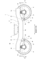
- FIG. 1 is a side view of a railway vehicle carriage 1 according to the first embodiment.
- a railcar bogie (hereinafter referred to as a bogie) 1 includes a bogie frame 3 connected to a vehicle body 30 via an air spring 2.
- the bogie frame 3 includes a lateral beam 4 extending in the vehicle width direction at the center of the bogie 1 in the longitudinal direction of the vehicle, and side beams 5 extending from both ends of the lateral beam 4 in the longitudinal direction of the vehicle.
- An axle 6 extending along the vehicle width direction is disposed on both sides of the bogie frame 3 in the longitudinal direction of the vehicle.
- Wheels 7 are press-fitted on both sides of the axle 6 in the vehicle width direction.
- the axle 6 and the wheel 7 constitute a wheel shaft 15.
- the pair of wheel shafts 15 provided on the carriage 1 are spaced apart from both sides of the carriage frame 3 in the longitudinal direction of the vehicle.
- Bearings 8 that rotatably support the wheels 7 on the outer side in the vehicle width direction than the wheels 7 are provided at both ends of the axle 6 in the vehicle width direction.
- the bearings 8 are accommodated in the axle box 10.
- the axle box 10 is elastically connected to the carriage frame 3 via an axle box support device 16.
- the axle box support device 16 includes an axle spring 20 that connects the axle box 10 and the longitudinal end portion 5a of the side beam 5 in the vertical direction, and an axle beam that connects the axle box 10 and the side beam 5 in the longitudinal direction of the vehicle. 21.
- the shaft beam 21 is formed integrally with the shaft box 10 and extends in the longitudinal direction of the vehicle.
- a cylindrical portion 25 (see FIG. 2) that opens to both sides in the vehicle width direction is formed at the tip of the shaft beam 21.
- a mandrel 24 is inserted into the internal space S of the cylindrical portion 25 via an elastic bush 23 (see FIG. 4).
- the side beam 5 is provided with a pair of receiving seats 22 and is connected to the shaft beam 21 via an elastic bush 23 and a mandrel 24.
- the receiving seat 22 is provided so as to protrude downward from the lower surface 5 b of the side beam 5, and a mandrel 24 is fitted in a groove portion 22 a (see FIG. 4) provided in the receiving seat 22.
- the lid member 18 is fixed to the receiving seat 22 with the bolt 19 so as to close the lower opening of the groove 22 a, whereby the mandrel 24 is sandwiched between the receiving seat 22 and the lid member 18. In this way, the mandrel 24 is connected to the receiving seat 22.
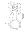
- FIG. 2 is an enlarged side view around the shaft beam 21 of the axle box support device 16 shown in FIG.
- FIG. 3 is an exploded side view of the cylindrical portion 25 of the shaft beam 21 shown in FIG. 2 and 3, illustration of the shaft spring 20, the rubber bush 23, the mandrel 24, the receiving seat 22 and the lid member 18 is omitted for convenience of explanation.
- the shaft beam 21 includes a shaft beam main body portion 41 and a shaft beam end portion 42 in which the tubular portion 25 is formed.
- the shaft beam main body 41 includes a pair of side plate portions 41a extending in the longitudinal direction of the vehicle and a connecting plate portion 41b (see FIG. 4) for connecting the pair of side plate portions 41a in the vehicle width direction.
- the shaft beam main body 41 has a substantially H-shaped cross-sectional shape when viewed from the longitudinal direction of the vehicle.
- the cylindrical portion 25 of the shaft beam end portion 42 includes a first half tube portion 26 formed integrally with the shaft beam main body portion 41 and a first half tube portion 26 overlapped with the first half tube portion 26 from the vehicle longitudinal direction outer side. It is divided into two half cylinder parts 27. The second half tube portion 27 is fixed to the first half tube portion 26 with a plurality of bolts 28. With this configuration, a truly cylindrical internal space S into which the rubber bush 23 and the mandrel 24 are inserted is formed.
- the bolt 28 is inserted from the first half cylinder part 26 side toward the second half cylinder part 27.
- the upper edge of the side plate portion 41a is viewed in a side view. It has a smooth curved shape (bow shape). Specifically, at least half of the upper edge of the side plate portion 41a on the first half cylinder portion 26 side is formed so as not to overlap the axis of the upper bolt 28 in the vertical direction. Further, the lower edge of the side plate portion 41a extends in parallel with the horizontal line from the axle box 10 so as not to overlap the axis of the lower bolt 28 in the vertical direction.
- the first half cylinder part 26 and the second half cylinder part 27 are manufactured by machining a metal material (for example, carbon steel) formed by casting or forging.
- the first half cylinder portion 26 includes a flat facing surface 26a and a hole 26b extending in a direction (vehicle longitudinal direction) orthogonal to the facing surface 26a.
- the facing surface 26 a is in surface contact with the facing surface 27 a of the second half cylinder portion 27.
- Bolts 28 are inserted through the holes 26b.
- the hole 26b is a drill hole and penetrates the first half-cylinder portion 26 in the vehicle longitudinal direction.
- the second half-cylinder portion 27 includes a flat facing surface 27a, a hole 27b extending in a direction (vehicle longitudinal direction) orthogonal to the facing surface 27a, and a flat processing reference surface 27d formed on the opposite side of the facing surface 27a. And an intermediate surface 27e positioned between the facing surface 27a and the processing reference surface 27d.
- the facing surface 27 a is in surface contact with the facing surface 26 a of the first half cylinder portion 26.
- Bolts 28 are inserted through the holes 27b.
- the hole 27 b is a screw hole in which a female screw is formed on the inner peripheral surface, and the first half cylinder part 26 and the second half cylinder part 27 are fixed by the bolt 28.
- the intermediate surface 27e is a surface that constitutes a recessed portion 27f in which the outer surface of the second semi-cylindrical portion 27 is recessed toward the facing surface 27a. Specifically, the intermediate surface 27e overlaps the facing surface 27a when viewed from the vehicle longitudinal direction.
- the screw hole 27b penetrates from the facing surface 27a to the intermediate surface 27e.
- bolt 28 penetrated by the screw hole 27b is located just before the intermediate surface 27e. Note that the tip of the bolt 28 may be flush with or protrude from the intermediate surface 27e.
- the intermediate surface 27e is provided from the viewpoint of sharing parts with the conventional structure and reducing the weight.
- a bolt 128 is inserted from the second half tube portion 127 side toward the first half tube portion 126 (see FIG. 6E).
- the conventional second half cylinder portion 127 is provided with a seating surface with which the head of the bolt 128 contacts. This seat surface corresponds to the intermediate surface 27e of the present embodiment. Therefore, unlike the conventional cylindrical portion 125, the cylindrical portion 25 of the present embodiment is reverse in the direction in which the bolt 28 is inserted.
- the intermediate surface 27e the bolt can be inserted from the same direction as the conventional one. It has a simple structure.
- the intermediate surface 27e and the recessed portion 27f are also formed to reduce the weight of the second half cylinder portion 27.
- the intermediate surface 27e and the hollow part 27f do not need to be formed.
- FIG. 4 is a cross-sectional view taken along line IV-IV shown in FIG.
- the mandrel 24 connects the shaft beam 21 and the side beam 5 and is inserted through the cylindrical portion 25 in the vehicle width direction as shown in FIG.
- the mandrel 24 has a cylindrical portion 24a, a pair of conical flange portions 24b, and a protruding end portion 24c.
- An elastic bush 23 is interposed between the tubular portion 25 and the mandrel 24.
- the elastic bush 23 is a rubber bush.
- the rubber bush 23 has a cylindrical portion 23 a and a pair of flange portions 23 b protruding outward in the radial direction, and is fitted on the mandrel 24. Further, when the rubber bush 23 is inserted into the cylindrical portion 25, the inner peripheral surface 25c of the cylindrical portion 25 (the inner peripheral surface 26c of the first semi-cylindrical portion 26 and the inner peripheral surface 27c of the second semi-cylindrical portion 27). ).
- the rubber bush 23 is designed to have anisotropy with respect to the elastic characteristics, the elastic characteristics of the rubber bush 23 are different unless the insertion position with respect to the cylindrical portion 25 is determined. It will be a thing. Therefore, it is necessary to position the rubber bush 23 with respect to the cylindrical portion 25 in order to make the elastic characteristics of the rubber bush 23 as designed.
- the rubber bush 23 is positioned with respect to the cylindrical portion 25 by providing the first semi-cylindrical portion 26 with the positioning pin 29.
- the positioning pin 29 is fixed to a pin hole 26 d provided on the inner peripheral surface 26 c of the first half cylinder portion 26.
- a concave portion 23d that is recessed inward in the radial direction is formed on the outer peripheral surface 23c of the cylindrical portion 23a of the rubber bush 23, a concave portion 23d that is recessed inward in the radial direction is formed.
- the protruding portion from the pin hole 26 d of the positioning pin 29 engages with the recess 23 d of the rubber bush 23, so that the rubber bush 23 cannot rotate around the center O of the cylindrical portion 25. Thereby, the rubber bush 23 is positioned with respect to the cylindrical portion 25.
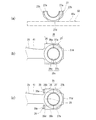
- FIG. 5 is a drawing for explaining a manufacturing procedure of the cylindrical portion 25 of the shaft beam 21 in the manufacturing method of the axle box support device 16 shown in FIG.
- an original shape of the second half cylinder portion 27 formed by casting or forging is prepared.
- the second half cylinder portion 27 is placed on the processing device 50 in a state where the machining reference surface 27 d is placed on the surface plate 50 a among the original shapes of the second half cylinder portion 27.
- the processing apparatus 50 is, for example, a machining center that has a tool automatic conversion function to perform a plurality of processing operations by one unit.
- the posture of the second half cylinder portion 27 installed in the processing apparatus 50 when performing the screw hole forming step is the same as the facing surface processing step.
- the first half-cylinder portion 26 formed integrally with the shaft beam main body portion 41 is prepared, and a facing surface processing step for flattening the facing surface 26a and a drill hole forming step for forming the drill holes 26b are performed. (Not shown).
- the facing surface 27a of the second half cylinder portion 27 subjected to the processing in FIG. 5A and the facing surface 26a of the first half cylinder portion 26 are brought into surface contact. .
- the first half cylinder part 26 and the second half cylinder part 27 are fixed with a temporary bolt (not shown).
- the inner peripheral surface machining step is performed on the tubular portion 25 in a state where the first half tubular portion 26 and the second half tubular portion 27 are overlapped and fixed. Specifically, a perfect circle is processed so that the inner peripheral surface 25c of the cylindrical portion 25 has a perfect circle shape when viewed from the vehicle width direction. Thereby, the rubber bush 23 inserted in the cylindrical part 25 can be favorably fastened by the inner peripheral surface 25c that has been processed into a perfect circle.
- a pin hole forming step is performed in which only the first half-cylinder portion 26 is left in the machining apparatus and a pin hole 26d into which the positioning pin 29 is inserted is formed on the inner peripheral surface 26c. That is, in the pin hole forming step, only the inner peripheral surface 26c of the first half cylinder part 26 is processed, and the inner peripheral surface 27c of the second half cylinder part 27 is not processed. In addition, you may perform a pin hole formation process at the time of the opposing surface processing process of the 1st half cylinder part 26 mentioned above.
- the pin hole forming step for the first semi-cylindrical portion 26 is completed, the processing for the cylindrical portion 25 is completed.
- the rubber bush 23 is brought into contact with the inner peripheral surface 26 c of the first half cylinder part 26, and the recess 23 d of the rubber bush 23 is engaged with the positioning pin 29 provided on the first half cylinder part 26. Then, the rubber bush 23 is brought into contact with the inner peripheral surface 27 c of the second half cylinder part 27, and the rubber bush 23 is sandwiched between the first half cylinder part 26 and the second half cylinder part 27.
- FIG. 6 is a drawing for explaining a manufacturing procedure of the cylindrical portion 125 of the shaft beam 121 in the conventional method of manufacturing the axle box support device 116.
- FIG. 6A shows a prototype of the second half-cylinder part 127 formed by casting or forging.
- the outer shape of the second half-cylinder part 127 is a semicircular shape, and on the side opposite to the facing surface 127a. Only an arc-shaped surface is formed. Therefore, unlike the present embodiment, a flat processing reference surface is not formed in the second half cylinder portion 127. Therefore, when the opposing surface 127a is planarized, it is necessary to support the second half cylinder part 127 with a different structure so that the second half cylinder part 127 is stably installed in the processing apparatus.
- the second half-cylinder part 127 is installed in the processing apparatus by inverting the second half-cylinder part 127 so that the facing surface 127a subjected to the planar processing faces down. To do. Then, a drill hole forming step for forming the hole 127b through which the bolt 128 is inserted, and a counterboring step for forming the seating surface 127e that contacts the head portion 128a of the bolt 128 are performed. As described above, in order to process the drill hole 127b with high accuracy and to planarize the seating surface 127e with high accuracy, it is necessary to invert the second half cylinder portion 127.
- the first half cylinder part 126 and the second half cylinder part 127 are placed on the processing apparatus in a state of being overlapped, and the inner peripheral surface 125 c of the cylindrical part 125 is set. Machining a perfect circle. Thereafter, of the first half cylinder portion 126 and the second half cylinder portion 127 subjected to the perfect circle processing, only the second half cylinder portion 127 is installed in the processing apparatus, and the pin hole 127d is formed on the inner peripheral surface 127c. To do.
- first half cylinder part 127 and the second half cylinder part 127 formed in this way are brought into contact with each other and fixed with bolts 128 and nuts 131.
- the axle box support device 16 of the railway vehicle carriage 1 configured as described above has the following effects.
- the second half cylinder part 27 can be stably placed on the surface plate 50a of the machining apparatus 50.
- the drilling process can be performed with high accuracy.
- workability is improved because there is no need for a step change operation for reversing the posture of the second half tube portion 27.
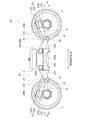
- FIG. 7 is a side view of the carriage 201 according to the second embodiment.
- a cart 201 according to the second embodiment is obtained by partially changing the configuration of the cart frame 3 from the cart 1 according to the first embodiment.
- the cart 201 which concerns on 2nd Embodiment is demonstrated about a different point from the cart 1 which concerns on 1st Embodiment.
- the carriage frame 203 includes a lateral beam 204 that extends in the vehicle width direction at the center of the longitudinal direction of the carriage 201, but unlike the configuration of the carriage frame 3 of the first embodiment, There is no side flash extending in the vehicle longitudinal direction from both ends 204a in the vehicle width direction.
- a pair of receiving seats 222 constituting the axle box support device 216 are provided at the vehicle width direction end portion 204a of the side beam 204 so as to protrude outward in the vehicle longitudinal direction. And the mandrel 24 of the cylindrical part 25 of the shaft beam 21 is clamped by the receiving seat 222 and the lid member 18.
- a leaf spring 209 extending in the longitudinal direction of the vehicle is bridged between the axle box 210 and the side cover 204.
- the leaf spring 209 supports both ends 204a in the vehicle width direction of the lateral beam 204 from below at the vehicle longitudinal direction center portion 209a, and the vehicle longitudinal direction end portion 209b of the leaf spring 209 is supported by the axle box 210. ing. That is, the leaf spring 209 has the function of the shaft spring 20 (primary suspension) of the first embodiment and the function of the side beam 5 of the first embodiment.
- the longitudinal end 209 b of the vehicle in the longitudinal direction of the leaf spring 209 is supported from below by the axle box 210 via a support member 231.
- the support member 231 is provided on the upper portion of the axle box 210.
- the support member 231 includes a receiving member 232 and a vibration isolating rubber 233.
- the receiving member 232 has a substantially rectangular shape in plan view, and has a bottom wall portion that supports the lower surface of the leaf spring 209 and outer wall portions that protrude upward from both ends in the vehicle longitudinal direction of the bottom wall portion. is doing.
- the upper surface of the support member 231 is inclined obliquely downward toward the center side in the vehicle longitudinal direction.
- the upper surface of the support member 231 does not need to be inclined as long as it is substantially parallel to the lower surface of the vehicle longitudinal direction end portion 209b of the leaf spring 209.
- the anti-vibration rubber 233 has a substantially cylindrical shape and is inserted between the axle box 210 and the receiving member 232.
- the axle box 210 has a spring seat 210 a that includes an upper surface that is in surface contact with the lower surface of the anti-vibration rubber 233.
- the upper surface of the spring seat 210a is also substantially parallel to the lower surface of the leaf spring 209, and is inclined obliquely downward toward the center in the vehicle longitudinal direction.
- Other configurations are the same as those in the first embodiment.
- the axle box support device 216 including the second half cylinder portion 27 having the flat processing reference surface 27d as in the first embodiment is not limited to the cart 1 including the general cart frame 3, but the leaf spring 209.
- the present invention can also be applied to the carriage 201 using the above.
- the present invention is not limited to the above-described embodiment, and the configuration can be changed, added, or deleted without departing from the spirit of the present invention.
- the above embodiments may be arbitrarily combined with each other. For example, some configurations or methods in one embodiment may be applied to other embodiments.
- a part of the configuration in the embodiment can be arbitrarily extracted separately from the other configurations in the embodiment.
- the cylindrical portion 25 is divided in the vehicle longitudinal direction, but may be divided in the vertical direction.
- a plurality of positioning pins 29 may be attached to the cylindrical portion 25. That is, a plurality of pin holes 26d are provided at arbitrary positions on the inner peripheral surface 26c of the first semi-cylindrical portion 26 with reference to the virtual line VL. It may be provided.
Landscapes
- Engineering & Computer Science (AREA)
- Mechanical Engineering (AREA)
- Vibration Prevention Devices (AREA)
- Springs (AREA)
- Vehicle Body Suspensions (AREA)
- Automobile Manufacture Line, Endless Track Vehicle, Trailer (AREA)
Abstract
鉄道車両用台車の軸箱支持装置の軸ばりは、軸箱から車両長手方向に延びる軸ばり本体部の先端に設けられ、車幅方向両側が開口する筒状部が形成された軸ばり端部を有する。筒状部は、軸ばり本体部に一体に形成された第1半筒部と、第1半筒部に対して車両長手方向一方側から重ね合わされた第2半筒部と、第1半筒部に第2半筒部を車両長手方向に締結するボルトと、を有する。第1半筒部は、第2半筒部と面接触する平坦な対向面と、対向面に直交する方向に延びて前記ボルトが挿通される孔と、を含む。第2半筒部は、第1半筒部の対向面と面接触する平坦な対向面と、対向面とは反対側に形成された平坦な加工基準面と、対向面に直交する方向に延びてボルトが挿通される孔と、を含む。
Description
本発明は、鉄道車両用台車の軸箱支持装置及びその製造方法に関する。
鉄道車両用台車では、車軸を回転自在に支持する軸受を収容する軸箱が軸箱支持装置を介して台車枠に支持されている。例えば、特許文献1に示す台車では、軸ばり式の軸箱支持装置が開示されており、軸箱が当該軸箱と一体に形成されて車両長手方向に延びる軸ばりを介して台車枠の側ばりに支持されている。
特許文献1において、側ばりと接続される軸ばりの車両長手方向一端には、車幅方向両側が開口する円筒部が形成されている。この円筒部にはゴムブッシュを介して心棒が挿通されており、当該円筒部の車幅方向両側から突出した心棒の両端部が台車枠に設けられた受け座の溝部に嵌合している。ゴムブッシュ及び心棒を挿入するために、軸ばりの円筒部は、上下方向に延びる分割線を境界として車両長手方向に分割されている。円筒部は、軸ばりと一体に形成された第1半筒部と、当該第1半筒部にボルト及びナットで締結される第2半筒部とから構成されている。
軸ばりと一体に形成された第1半筒部に第2半筒部を締結可能とするにあたっては、当該第2半筒部を機械加工する必要があった。具体的には、第2半筒部のうち第1半筒部との合わせ面の平面度を高める平面加工を行う工程に加えて、ボルトが挿通される挿通孔を形成する工程、ボルト頭部と接触する座面の平面度を高める加工を行う工程が必要であった。
しかし、ボルトを挿通する挿通孔を形成する工程では、当該挿通孔を精度良く形成する必要があるため、第2半筒部を加工装置に安定して設置する必要があった。ここで、第2半筒部の外形は半円形状であるため、平坦な第1半筒部との合わせ面が加工装置の定盤に安定して載置できるように、直前の工程では加工面である合わせ面を精度良く上側に向けて治具等により把持した後、第2半筒部を反転させる段取り替えの作業も必要であった。
そこで本発明は、鉄道車両用台車の軸箱支持装置において、軸ばりと一体に形成された第1半筒部に締結される第2半筒部に必要な機械加工の作業工数を低減することを目的としている。
本発明の一形態に係る鉄道車両用台車の軸箱支持装置は、車軸を支持する軸受が収容される軸箱から車両長手方向に延びる軸ばり本体部と、前記軸ばり本体部の先端に設けられ、車幅方向両側が開口する筒状部が形成された軸ばり端部とを有する軸ばりと、前記筒状部の内部空間に車幅方向に挿通される心棒と、前記筒状部と前記心棒との間に介装される弾性ブッシュと、台車枠に設けられ、前記心棒の両端部が接続される受け座と、を備え、前記筒状部は、前記軸ばり本体部に一体に形成された第1半筒部と、前記第1半筒部に対して車両長手方向一方側から重ね合わされた第2半筒部と、前記第1半筒部に前記第2半筒部を車両長手方向に締結するボルトと、を有し、前記第1半筒部は、前記第2半筒部と面接触する平坦な対向面と、前記対向面に直交する方向に延びて前記ボルトが挿通される孔と、を含み、前記第2半筒部は、前記第1半筒部の前記対向面と面接触する平坦な対向面と、前記対向面とは反対側に形成された平坦な加工基準面と、前記対向面に直交する方向に延びて前記ボルトが挿通される孔と、を含む。
前記構成によれば、第2半筒部において、加工基準面を設けたことで、当該第2半筒部を加工装置の定盤に安定的に載置させることができ、対向面を加工する工程と孔を形成する工程とを精度良く行うことができる。また、かかる二つの工程を行う際に、第2半筒部の姿勢を反転させる段取り替えの作業が必要ないので、作業性が向上する。
本発明の一形態に係る鉄道車両用台車の軸箱支持装置の製造方法は、車軸を支持する軸受が収容される軸箱から車両長手方向に延びる軸ばり本体部と、前記軸ばり本体部の先端に設けられ、車幅方向両側が開口する筒状部が形成された軸ばり端部とを有する軸ばりを備え、前記筒状部は、前記軸ばり本体部に一体に形成された第1半筒部と、前記第1半筒部に対して重ね合わせられた第2半筒部と、前記第1半筒部に前記第2半筒部を締結するボルトとを有する、軸箱支持装置を製造する方法であって、前記第2半筒部のうち前記第1半筒部と面接触する平坦な対向面とは反対側に形成された平坦な加工基準面を加工装置の定盤に接触させた状態で前記第2半筒部を前記加工装置に設置して、前記対向面を平面加工する対向面加工工程と、前記対向面加工工程と同一の設置姿勢で前記第2半筒部に前記ボルトが挿通される孔を形成する孔形成工程と、を備える。
前記方法によれば、第2半筒部において、加工基準面を設けたことで、当該第2半筒部を加工装置の定盤に安定的に載置させることができ、対向面加工工程と孔形成工程とを精度良く行うことができる。また、かかる二つの工程を行う際に、第2半筒部の姿勢を反転させる段取り替えの作業が必要ないので作業性が向上する。更に、第1半筒部に対して第2半筒部を重ね合わせた状態で筒状部の内周面を真円加工することで、筒状部に挿入される弾性ブッシュを真円加工された筒状部の内周面によって良好に締め付けることができる。
本発明によれば、鉄道車両用台車の軸箱支持装置において、軸ばりと一体に形成された第1半筒部に締結される第2半筒部に必要な機械加工の作業工数を低減することができる。
以下、図面を参照しながら実施形態について説明する。なお、同一の又は対応する要素には全ての図を通じて同一の符号を付して重複する詳細説明を省略する。
(第1実施形態)
図1は、第1実施形態に係る鉄道車両用台車1の側面図である。図1に示すように、鉄道車両用台車(以下、台車と呼ぶ)1は、空気バネ2を介して車体30と接続される台車枠3を備えている。台車枠3は、台車1の車両長手方向中央において車幅方向に延びる横ばり4と、横ばり4の車幅方向両端部から車両長手方向に延びる側ばり5とを有している。
図1は、第1実施形態に係る鉄道車両用台車1の側面図である。図1に示すように、鉄道車両用台車(以下、台車と呼ぶ)1は、空気バネ2を介して車体30と接続される台車枠3を備えている。台車枠3は、台車1の車両長手方向中央において車幅方向に延びる横ばり4と、横ばり4の車幅方向両端部から車両長手方向に延びる側ばり5とを有している。
台車枠3の車両長手方向両側には、それぞれ車幅方向に沿って延びる車軸6が配置されている。車軸6の車幅方向両側には車輪7が圧入される。車軸6及び車輪7は輪軸15を構成する。そして、台車1に設けられた一対の輪軸15は、台車枠3の車両長手方向両側に離間して配置されている。車軸6の車幅方向両側の端部には、車輪7よりも車幅方向外側にて車輪7を回転自在に支持する軸受8が設けられ、その軸受8は軸箱10に収容される。
軸箱10は、軸箱支持装置16を介して台車枠3に弾性的に連結されている。軸箱支持装置16は、軸箱10と側ばり5の車両長手方向端部5aとを上下方向に接続する軸バネ20と、軸箱10と側ばり5とを車両長手方向に連結する軸ばり21とを備えている。軸ばり21は、軸箱10と一体に成形されて車両長手方向に延びている。軸ばり21の先端には、車幅方向両側に開口する筒状部25(図2参照)が形成されている。筒状部25の内部空間Sには、弾性ブッシュ23(図4参照)を介して心棒24が挿通されている。
そして、側ばり5には、一対の受け座22が設けられ、弾性ブッシュ23、心棒24を介して軸ばり21に連結されている。具体的には、受け座22は、側ばり5の下面5bから下方に突出して設けられ、受け座22に設けられた溝部22a(図4参照)に心棒24が嵌合している。この状態で、溝部22aの下側開口を閉鎖するように蓋部材18がボルト19で受け座22に固定されることで、心棒24が受け座22と蓋部材18とで挟持されている。このようにして、心棒24が受け座22に接続される。
図2は、図1に示す軸箱支持装置16の軸ばり21周辺の拡大側面図である。図3は、図2に示す軸ばり21の筒状部25の分解側面図である。なお、図2及び3では、説明の便宜上、軸バネ20、ゴムブッシュ23、心棒24、受け座22及び蓋部材18の図示を省略している。図2及び3に示すように、軸ばり21は、軸ばり本体部41と、筒状部25が形成された軸ばり端部42とを有している。軸ばり本体部41は、車両長手方向に延びる一対の側板部41aと、一対の側板部41aを車幅方向に連結する連結板部41b(図4参照)とを含んでいる。これにより、軸ばり本体部41は、車両長手方向から見て略H形の断面形状を有している。
軸ばり端部42の筒状部25は、軸ばり本体部41に一体に形成された第1半筒部26と、当該第1半筒部26に対して車両長手方向外側から重ね合わされた第2半筒部27とに分割されている。そして、第2半筒部27は、第1半筒部26に複数のボルト28で固定されている。この構成により、ゴムブッシュ23及び心棒24が挿通される真円柱状の内部空間Sが形成される。
ボルト28は、第1半筒部26側から第2半筒部27に向けて挿通される。ここで、ボルト28を第1半筒部26から挿通する際に、ボルト28と軸ばり本体部41の側板部41aとが干渉するのを防ぐために、側板部41aの上縁を、側面視で、滑らかな曲線形状(弓型形状)としている。具体的には、側板部41aの上縁の少なくとも第1半筒部26側の半分は、上側のボルト28の軸線と上下方向に重ならないように形成されている。また、側板部41aの下縁は、下側のボルト28の軸線と上下方向に重ならないように、軸箱10から水平線と平行に延びている。
第1半筒部26及び第2半筒部27は、金属材料(例えば、炭素鋼)を鋳造又は鍛造により成形したものを機械加工することによって製作される。第1半筒部26は、平坦な対向面26aと、対向面26aに直交する方向(車両長手方向)に延びる孔26bとを含んでいる。対向面26aは、第2半筒部27の対向面27aと面接触する。孔26bには、ボルト28が挿通される。ここで、孔26bはキリ孔であり、第1半筒部26を車両長手方向に貫通している。
第2半筒部27は、平坦な対向面27aと、対向面27aに直交する方向(車両長手方向)に延びる孔27bと、対向面27aとは反対側に形成された平坦な加工基準面27dとを含んでおり、更に、対向面27aと加工基準面27dとの間に位置する中間面27eを含んでいる。対向面27aは、第1半筒部26の対向面26aと面接触する。孔27bには、ボルト28が挿通される。ここで、孔27bは、その内周面に雌ネジが形成されたネジ孔であり、ボルト28により第1半筒部26と第2半筒部27とが固定される。
中間面27eは、第2半筒部27の外面を対向面27a側に窪ませた窪み部27fを構成する面である。具体的には、中間面27eは、車両長手方向から見て対向面27aと重なっている。また、ネジ孔27bは、対向面27aから中間面27eにかけて貫通している。そして、ネジ孔27bに挿通されるボルト28の先端部は、中間面27eの直前に位置している。なお、ボルト28の先端部は中間面27eに対して面一または突出していてもよい。
ここで、中間面27eは、従来構造との部品共通化及び軽量化の観点から設けている。
後述するように、従来の筒状部125は第2半筒部127側から第1半筒部126に向けてボルト128が挿通されている(図6(e)参照)。従来の第2半筒部127にはボルト128の頭部が接触する座面が設けられている。この座面が本実施形態の中間面27eに相当する。したがって、本実施形態の筒状部25は、従来の筒状部125と異なりボルト28を挿通する向きが逆であるが、中間面27eを設けることで、従来と同方向からでもボルトを挿通可能な構成としている。また、中間面27e及び窪み部27fは、第2半筒部27の軽量化のためにも形成されている。なお、本実施形態の筒状部25において、中間面27e及び窪み部27fは形成されていなくてもよい。
後述するように、従来の筒状部125は第2半筒部127側から第1半筒部126に向けてボルト128が挿通されている(図6(e)参照)。従来の第2半筒部127にはボルト128の頭部が接触する座面が設けられている。この座面が本実施形態の中間面27eに相当する。したがって、本実施形態の筒状部25は、従来の筒状部125と異なりボルト28を挿通する向きが逆であるが、中間面27eを設けることで、従来と同方向からでもボルトを挿通可能な構成としている。また、中間面27e及び窪み部27fは、第2半筒部27の軽量化のためにも形成されている。なお、本実施形態の筒状部25において、中間面27e及び窪み部27fは形成されていなくてもよい。
図4は、図2に示すIV-IV線断面図である。上述のように、心棒24は、軸ばり21と側ばり5とを連結し、図4に示すように、筒状部25に車幅方向に挿通されている。心棒24は、円柱部24aと、一対の円錐状のフランジ部24bと、突起状の端部24cとを有している。筒状部25と心棒24との間には弾性ブッシュ23が介装されている。本実施形態では、弾性ブッシュ23は、ゴムブッシュである。
ゴムブッシュ23は、円筒部23aと、径方向外方に突出した一対のフランジ部23bとを有し、心棒24に外嵌される。また、ゴムブッシュ23は、筒状部25に挿通されると、筒状部25の内周面25c(第1半筒部26の内周面26c及び第2半筒部27の内周面27c)によって締め付けられる。ここで、ゴムブッシュ23は弾性特性に関して異方性を有するように設計しているため、筒状部25に対して挿入する位置を決めておかないと、当該ゴムブッシュ23の弾性特性も異なったものとなる。そこで、ゴムブッシュ23の弾性特性を設計通りにするために筒状部25に対するゴムブッシュ23の位置決めを行う必要がある。
そこで、本実施形態では、第1半筒部26に位置決めピン29を設けることで、ゴムブッシュ23が筒状部25に対して位置決めされている。位置決めピン29は、第1半筒部26の内周面26cに設けられたピン孔26dに固定されている。
ゴムブッシュ23の円筒部23aの外周面23cには、径方向内方へと窪む凹部23dが形成されている。位置決めピン29のうちピン孔26dからの突出部分がゴムブッシュ23の凹部23dに係合することで、ゴムブッシュ23が筒状部25の中心O周りに回転不能になる。これにより、ゴムブッシュ23は筒状部25に対して位置決めされる。
以上のように構成される軸箱支持装置16について、その製造工程について説明する。
図5は、図2に示す軸箱支持装置16の製造方法のうち軸ばり21の筒状部25の製作手順を説明するための図面である。まず、鋳造又は鍛造により成形した第2半筒部27の原形物を準備する。そして、図5(a)に示すように、第2半筒部27の原形物のうち加工基準面27dを定盤50aに載置させた状態で、第2半筒部27を加工装置50に設置する。ここで、加工装置50は、例えば、工具の自動変換機能を有することで複数の加工作業を1台で行うマシニングセンタである。そして、第2半筒部27を加工装置50に設置した状態で、対向面27aを平面加工する対向面加工工程と、ネジ孔27bを形成するネジ孔形成工程とを行う。したがって、ネジ孔形成工程を行うときの加工装置50に設置する第2半筒部27の姿勢は、対向面加工工程と同一である。
次に、軸ばり本体部41と一体に形成された第1半筒部26を準備して、対向面26aを平面加工する対向面加工工程とキリ孔26bを形成するキリ孔形成工程とを行う(図示せず)。
その後、図5(b)に示すように、図5(a)で加工処理を行った第2半筒部27の対向面27aと、第1半筒部26の対向面26aとを面接触させる。このとき、図示しない仮ボルトで第1半筒部26と第2半筒部27とを固定する。
そして、第1半筒部26と第2半筒部27とを重ね合わせて固定した状態で、筒状部25に対して内周面加工工程を行う。具体的には、筒状部25の内周面25cが車幅方向から見て真円形状を有するように真円加工する。これにより、筒状部25に挿入されるゴムブッシュ23を真円加工された内周面25cによって良好に締め付けることができる。
内周面加工工程が終了すると、第1半筒部26のみを加工装置に残して、その内周面26cに位置決めピン29が挿入されるピン孔26dを形成するピン孔形成工程を行う。即ち、ピン孔形成工程では、第1半筒部26の内周面26cを加工するのみで、第2半筒部27の内周面27cには加工しない。なお、ピン孔形成工程は、上述した第1半筒部26の対向面加工工程のときに行ってもよい。第1半筒部26に対するピン孔形成工程が終了すると、筒状部25に対する加工が完了する。
次に、第1半筒部26の内周面26cにゴムブッシュ23を当接させ、第1半筒部26に設けられた位置決めピン29にゴムブッシュ23の凹部23dを係合させる。そして、第2半筒部27の内周面27cにゴムブッシュ23を当接させ、第1半筒部26及び第2半筒部27によりゴムブッシュ23を挟持する。
最後に、第1及び第2半筒部26,27の各対向面26a,27aを互いに当接させてボルト28によって固定する。このようにして、軸箱支持装置16が形成される。
ここで、本実施形態の製造方法と比較するため、従来の軸箱支持装置の製造方法について説明する。
図6は、従来の軸箱支持装置116の製造方法のうち軸ばり121の筒状部125の製作手順を説明するための図面である。以下では、本実施形態に係る筒状部25に対して従来の筒状部125が異なる点について説明する。図6(a)は、鋳造又は鍛造により成形した第2半筒部127の原形物を示しており、第2半筒部127の外形は半円形状であり、対向面127aと反対側には円弧状の面のみが形成されている。そのため、本実施形態と異なり、第2半筒部127には平坦な加工基準面は形成されていない。よって、対向面127aを平面加工する場合には、第2半筒部127が加工装置に安定して設置されるように当該第2半筒部127を別構造で支持する必要がある。
次に、図6(b)に示すように、第2半筒部127を反転させて、平面加工が施された対向面127aが下になるように第2半筒部127を加工装置に設置する。そして、ボルト128が挿通する孔127bを形成するキリ孔形成工程と、ボルト128の頭部128aと接触する座面127eを形成するザクリ加工工程とを行う。
このように、キリ孔127bを精度良く加工するとともに、座面127eを高精度に平面加工するために、第2半筒部127を反転させる作業が必要となる。
このように、キリ孔127bを精度良く加工するとともに、座面127eを高精度に平面加工するために、第2半筒部127を反転させる作業が必要となる。
次に、図6(c)に示すように、第1半筒部126と第2半筒部127とを重ね合わせた状態で加工装置に設置して、筒状部125の内周面125cを真円加工する。その後、真円加工が施された第1半筒部126及び第2半筒部127のうち、加工装置に第2半筒部127のみを設置して、内周面127cにピン孔127dを形成する。
最後に、このように形成された第1半筒部127と第2半筒部127とを互いに当接させてボルト128及びナット131により固定する。
このように、従来の軸箱支持装置116の製造においては、第2半筒部127に対する機械加工の作業工程として、対向面加工工程及びキリ孔形成工程に加えて、ザグリ加工工程とピン孔形成工程とが必要である。そして、何度も段取替えの作業が発生するため多くの工数が発生する。
以上のように構成された鉄道車両用台車1の軸箱支持装置16は、以下の効果を奏する。
第2半筒部27において、加工基準面27dを設けたことで、当該第2半筒部27を加工装置50の定盤50aに安定的に載置させることができ、対向面加工工程とネジ孔加工工程を精度良く行うことができる。また、かかる二つの工程を行う際に、第2半筒部27の姿勢を反転させる段取り替えの作業が必要無いので作業性が向上する。
また、第2半筒部27の孔27bにはタップ加工が施されるので、第1半筒部26と第2半筒部27とを固定する際にナットが不要になるとともに、ザグリ加工も不要になる。
また、ゴムブッシュ23の位置決めピン29を第1半筒部26に取り付けることで、第2半筒部127に取り付けられる従来の構成と比べて、第2半筒部27の機械加工に必要な作業工数をより低減することができる。
(第2実施形態)
図7は、第2実施形態に係る台車201の側面図である。第2実施形態に係る台車201は、第1実施形態に係る台車1から台車枠3の構成等を一部変更したものである。以下では、第2実施形態に係る台車201について、第1実施形態に係る台車1と異なる点について説明する。
図7は、第2実施形態に係る台車201の側面図である。第2実施形態に係る台車201は、第1実施形態に係る台車1から台車枠3の構成等を一部変更したものである。以下では、第2実施形態に係る台車201について、第1実施形態に係る台車1と異なる点について説明する。
図7に示すように、台車枠203は、台車201の車両長手方向中央において車幅方向に延びる横ばり204を備えるが、第1実施形態の台車枠3の構成とは異なり、横ばり204の車幅方向両端部204aから車両長手方向に延びる側ばりを備えていない。横ばり204の車幅方向端部204aには、軸箱支持装置216を構成する一対の受け座222が車両長手方向外方に突出して設けられている。そして、受け座222と蓋部材18とによって、軸ばり21のうち筒状部25の心棒24が挟持されている。
また、軸箱210と横ばり204との間には、車両長手方向に延びる板バネ209が架け渡されている。板バネ209は、その車両長手方向中央部209aにおいて、横ばり204の車幅方向両端部204aを下方から支持しており、板バネ209の車両長手方向端部209bは、軸箱210に支持されている。即ち、板バネ209は、第1実施形態の軸バネ20(一次サスペンション)の機能と第1実施形態の側ばり5の機能とを有している。
板バネ209の車両長手方向端部209bは、支持部材231を介して軸箱210に下方から支持されている。支持部材231は軸箱210の上部に設けられている。そして、支持部材231は、受け部材232と、防振ゴム233とを有している。受け部材232は、平面視で略矩形の形状を有しており、板バネ209の下面を支持する底壁部と、当該底壁部の車両長手方向両端から上方に突出する外壁部とを有している。支持部材231の上面は、車両長手方向の中央側に向けて斜め下方に傾斜している。なお、支持部材231の上面は、板バネ209のうち車両長手方向端部209bの下面と略平行であれば、傾斜していなくてもよい。
防振ゴム233は略円柱状であり、軸箱210と受け部材232との間に挿入されている。軸箱210は、防振ゴム233の下面と面接触する上面を含むバネ座210aを有している。バネ座210aの上面も、板バネ209の下面と略平行であり、車両長手方向の中央側に向けて斜め下方に傾斜している。これ以外の構成は、第1実施形態と同様である。
このような第2実施形態によっても第1実施形態と同様の効果が得られる。即ち、第1実施形態と同様に平坦な加工基準面27dを有する第2半筒部27を備えた軸箱支持装置216は、一般的な台車枠3を備える台車1に限らず、板バネ209を用いた台車201においても適用可能である。
なお、本発明は前述した実施形態に限定されるものではなく、本発明の趣旨を逸脱しない範囲でその構成を変更、追加、又は削除することができる。前記各実施形態は互いに任意に組み合わせてもよく、例えば1つの実施形態中の一部の構成又は方法を他の実施形態に適用してもよい。また、実施形態中の一部の構成は、その実施形態中の他の構成から分離して任意に抽出可能である。前述の実施形態では、筒状部25は車両長手方向に分割されていたが、上下方向に分割されていてもよい。また、位置決めピン29は、筒状部25に複数取り付けられてもよい、即ち、仮想線VLを基準として第1半筒部26の内周面26cの任意の位置には、ピン孔26dが複数設けられてもよい。
1,201 鉄道車両用台車
6 車軸
8 軸受
10 軸箱
16,216 軸箱支持装置
21 軸ばり
22,222 受け座
23 ゴムブッシュ(弾性ブッシュ)
23c 外周面
23d 凹部
24 心棒
25 筒状部
25c 内周面
26 第1半筒部
26a 対向面
26b キリ孔(孔)
26c 内周面
27 第2半筒部
27a 対向面
27b ネジ孔(孔)
27d 加工基準面
28 ボルト
29 位置決めピン
41 軸ばり本体部
42 軸ばり端部
50 加工装置
50a 定盤
S 内部空間
6 車軸
8 軸受
10 軸箱
16,216 軸箱支持装置
21 軸ばり
22,222 受け座
23 ゴムブッシュ(弾性ブッシュ)
23c 外周面
23d 凹部
24 心棒
25 筒状部
25c 内周面
26 第1半筒部
26a 対向面
26b キリ孔(孔)
26c 内周面
27 第2半筒部
27a 対向面
27b ネジ孔(孔)
27d 加工基準面
28 ボルト
29 位置決めピン
41 軸ばり本体部
42 軸ばり端部
50 加工装置
50a 定盤
S 内部空間
Claims (5)
- 車軸を支持する軸受が収容される軸箱から車両長手方向に延びる軸ばり本体部と、前記軸ばり本体部の先端に設けられ、車幅方向両側が開口する筒状部が形成された軸ばり端部とを有する軸ばりと、
前記筒状部の内部空間に車幅方向に挿通される心棒と、
前記筒状部と前記心棒との間に介装される弾性ブッシュと、
台車枠に設けられ、前記心棒の両端部が接続される受け座と、を備え、
前記筒状部は、前記軸ばり本体部に一体に形成された第1半筒部と、前記第1半筒部に対して車両長手方向一方側から重ね合わされた第2半筒部と、前記第1半筒部に前記第2半筒部を車両長手方向に締結するボルトと、を有し、
前記第1半筒部は、前記第2半筒部と面接触する平坦な対向面と、前記対向面に直交する方向に延びて前記ボルトが挿通される孔と、を含み、
前記第2半筒部は、前記第1半筒部の前記対向面と面接触する平坦な対向面と、前記対向面とは反対側に形成された平坦な加工基準面と、前記対向面に直交する方向に延びて前記ボルトが挿通される孔と、を含む、鉄道車両用台車の軸箱支持装置。 - 前記第1半筒部の前記孔は、キリ孔であり、
前記第2半筒部の前記孔は、ネジ孔であり、
前記ボルトは、前記第1半筒部から前記第2半筒部に向けて前記孔に挿通される、請求項1に記載の鉄道車両用台車の軸箱支持装置。 - 前記筒状部に取り付けられ、前記弾性ブッシュに係合される位置決めピンを更に備え、
前記弾性ブッシュの外周面には、前記ピンが係合される凹部が形成されており、
前記ピンは、前記第1半筒部の内周面に取り付けられる、請求項1又は2に記載の鉄道車両用台車の軸箱支持装置。 - 車軸を支持する軸受が収容される軸箱から車両長手方向に延びる軸ばり本体部と、前記軸ばり本体部の先端に設けられ、車幅方向両側が開口する筒状部が形成された軸ばり端部とを有する軸ばりを備え、前記筒状部は、前記軸ばり本体部に一体に形成された第1半筒部と、前記第1半筒部に対して重ね合わせられた第2半筒部と、前記第1半筒部に前記第2半筒部を締結するボルトとを有する、軸箱支持装置を製造する方法であって、
前記第2半筒部のうち前記第1半筒部と面接触する平坦な対向面とは反対側に形成された平坦な加工基準面を加工装置の定盤に接触させた状態で前記第2半筒部を前記加工装置に設置して、前記対向面を平面加工する対向面加工工程と、
前記対向面加工工程と同一の姿勢で前記第2半筒部に前記ボルトが挿通される孔を形成する孔形成工程と、
前記第1半筒部に対して前記第2半筒部を重ね合わせた状態で、前記筒状部の内周面を真円加工する内周面加工工程と、を備える、鉄道車両用台車の軸箱支持装置の製造方法。 - 前記孔形成工程は、前記ボルトが挿通されるネジ孔を形成するネジ孔形成工程であり、
前記ボルトは、前記第1半筒部から前記第2半筒部に向けて挿通される、請求項4に記載の鉄道車両用台車の軸箱支持装置の製造方法。
Priority Applications (3)
| Application Number | Priority Date | Filing Date | Title |
|---|---|---|---|
| US16/065,887 US10906565B2 (en) | 2015-12-25 | 2016-11-29 | Axle box suspension of railcar bogie and method of producing the same |
| CN201680075669.4A CN108367762B (zh) | 2015-12-25 | 2016-11-29 | 铁道车辆用转向架的轴箱支持装置及其制造方法 |
| SG11201805406TA SG11201805406TA (en) | 2015-12-25 | 2016-11-29 | Axle box suspension of railcar bogie and method of producing the same |
Applications Claiming Priority (2)
| Application Number | Priority Date | Filing Date | Title |
|---|---|---|---|
| JP2015252983A JP6670098B2 (ja) | 2015-12-25 | 2015-12-25 | 鉄道車両用台車の軸箱支持装置及びその製造方法 |
| JP2015-252983 | 2015-12-25 |
Publications (1)
| Publication Number | Publication Date |
|---|---|
| WO2017110046A1 true WO2017110046A1 (ja) | 2017-06-29 |
Family
ID=59089884
Family Applications (1)
| Application Number | Title | Priority Date | Filing Date |
|---|---|---|---|
| PCT/JP2016/005006 Ceased WO2017110046A1 (ja) | 2015-12-25 | 2016-11-29 | 鉄道車両用台車の軸箱支持装置及びその製造方法 |
Country Status (6)
| Country | Link |
|---|---|
| US (1) | US10906565B2 (ja) |
| JP (1) | JP6670098B2 (ja) |
| CN (1) | CN108367762B (ja) |
| SG (1) | SG11201805406TA (ja) |
| TW (1) | TWI635008B (ja) |
| WO (1) | WO2017110046A1 (ja) |
Families Citing this family (7)
| Publication number | Priority date | Publication date | Assignee | Title |
|---|---|---|---|---|
| JP6595904B2 (ja) * | 2015-12-25 | 2019-10-23 | 川崎重工業株式会社 | 鉄道車両用軸箱及びその製造方法 |
| JP7037417B2 (ja) * | 2018-03-30 | 2022-03-16 | 川崎車両株式会社 | 鉄道車両の軸箱支持装置及び弾性ブッシュ軸体 |
| US11814087B2 (en) * | 2018-04-17 | 2023-11-14 | Kawasaki Railcar Manufacturing Co., Ltd. | Support structure of railcar bogie and method of supporting railcar bogie |
| CN109108866B (zh) * | 2018-08-16 | 2020-06-30 | 中车唐山机车车辆有限公司 | 用于轴箱转臂节点的组装装置 |
| CN109532917B (zh) * | 2019-01-25 | 2023-09-29 | 西南交通大学 | 一种轨道车辆一系悬挂结构 |
| DE102019216088A1 (de) * | 2019-10-18 | 2021-04-22 | Siemens Mobility GmbH | Anordnung zur Positionierung eines Rads eines Schienenfahrzeugs |
| US11674549B2 (en) * | 2020-05-11 | 2023-06-13 | Columbia Insurance Company | Bearing assembly for tufting machine cutting attachment |
Citations (3)
| Publication number | Priority date | Publication date | Assignee | Title |
|---|---|---|---|---|
| JP2002211395A (ja) * | 2001-01-16 | 2002-07-31 | Tokai Rubber Ind Ltd | 鉄道車両の軸ハリ連結用防振ゴムブッシュ組付体 |
| JP2006298172A (ja) * | 2005-04-20 | 2006-11-02 | Toyo Tire & Rubber Co Ltd | 軸箱支持用弾性体 |
| JP2010184684A (ja) * | 2009-02-13 | 2010-08-26 | Kawasaki Heavy Ind Ltd | 鉄道車両用軸箱支持装置 |
Family Cites Families (7)
| Publication number | Priority date | Publication date | Assignee | Title |
|---|---|---|---|---|
| US2560413A (en) * | 1949-02-26 | 1951-07-10 | Eaton Mfg Co | Dowel |
| BE540598A (ja) * | 1954-08-19 | |||
| JPH074722B2 (ja) * | 1987-09-16 | 1995-01-25 | 川鉄建材工業株式会社 | 構造部材接合用球状ノードの製造方法 |
| EP0542722B1 (en) * | 1988-09-01 | 1995-04-26 | Kawasaki Jukogyo Kabushiki Kaisha | Axle box suspension |
| CN201193037Y (zh) * | 2008-08-15 | 2009-02-11 | 铁道部运输局 | 高速动车组转向架的转臂式轴箱定位装置 |
| JP6068984B2 (ja) * | 2013-01-10 | 2017-01-25 | 川崎重工業株式会社 | 鉄道車両用台車 |
| JP6111187B2 (ja) | 2013-12-05 | 2017-04-05 | 川崎重工業株式会社 | 鉄道車両用軸箱支持装置 |
-
2015
- 2015-12-25 JP JP2015252983A patent/JP6670098B2/ja active Active
-
2016
- 2016-11-29 WO PCT/JP2016/005006 patent/WO2017110046A1/ja not_active Ceased
- 2016-11-29 US US16/065,887 patent/US10906565B2/en active Active
- 2016-11-29 SG SG11201805406TA patent/SG11201805406TA/en unknown
- 2016-11-29 CN CN201680075669.4A patent/CN108367762B/zh active Active
- 2016-12-07 TW TW105140321A patent/TWI635008B/zh active
Patent Citations (3)
| Publication number | Priority date | Publication date | Assignee | Title |
|---|---|---|---|---|
| JP2002211395A (ja) * | 2001-01-16 | 2002-07-31 | Tokai Rubber Ind Ltd | 鉄道車両の軸ハリ連結用防振ゴムブッシュ組付体 |
| JP2006298172A (ja) * | 2005-04-20 | 2006-11-02 | Toyo Tire & Rubber Co Ltd | 軸箱支持用弾性体 |
| JP2010184684A (ja) * | 2009-02-13 | 2010-08-26 | Kawasaki Heavy Ind Ltd | 鉄道車両用軸箱支持装置 |
Also Published As
| Publication number | Publication date |
|---|---|
| TW201726460A (zh) | 2017-08-01 |
| JP6670098B2 (ja) | 2020-03-18 |
| CN108367762B (zh) | 2020-05-01 |
| SG11201805406TA (en) | 2018-07-30 |
| TWI635008B (zh) | 2018-09-11 |
| JP2017114365A (ja) | 2017-06-29 |
| US20190009798A1 (en) | 2019-01-10 |
| US10906565B2 (en) | 2021-02-02 |
| CN108367762A (zh) | 2018-08-03 |
Similar Documents
| Publication | Publication Date | Title |
|---|---|---|
| WO2017110046A1 (ja) | 鉄道車両用台車の軸箱支持装置及びその製造方法 | |
| JP5225603B2 (ja) | 防振装置 | |
| US10316920B2 (en) | Anti-vibration device | |
| JP2011162188A (ja) | トランスバースリンクおよびトランスバースリンクの製造方法 | |
| KR20080108337A (ko) | 일체형 피벗 조립체를 갖는 서스펜션 링크 | |
| CN111801235A (zh) | 轮轴结构 | |
| WO2018139251A1 (ja) | 鉄道車両の軸箱支持装置 | |
| JP6595904B2 (ja) | 鉄道車両用軸箱及びその製造方法 | |
| US11583983B2 (en) | Assembly tool for changing bushings for lower arm | |
| EP2876017B1 (en) | Axlebox comprising split housing parts, vehicle comprising at least one such axlebox and processes | |
| JP3161088U (ja) | リアアクスル | |
| JP6557596B2 (ja) | 鉄道車両用台車、その輪重調整方法、及び輪重調整システム | |
| JP2009241771A (ja) | 軸箱支持装置用軸ばね座及びその製造方法 | |
| WO2017110044A1 (ja) | 鉄道車両用台車の輪重調整具、それを備えた鉄道車両用台車、及び鉄道車両用台車の製造方法 | |
| US10378418B2 (en) | Vertical hanger isolator assembly | |
| JP2007127239A (ja) | ゴムブッシュ付きバー | |
| CN103038068A (zh) | 轨道式车辆 | |
| CN107076642B (zh) | 车辆约束装置 | |
| CN204578758U (zh) | 一种用于车内噪声测试的麦克风固定装置 | |
| JP2005188648A (ja) | 油圧緩衝器のナックルブラケット構造 | |
| KR100893211B1 (ko) | 가이드브라켓 및 그 제조방법 | |
| KR20160036744A (ko) | 철도 차량용 브레이크디스크 체결장치 | |
| JP6709694B2 (ja) | ブッシュ着脱装置 | |
| CN212169694U (zh) | 一种用于汽车中桥壳加工的夹具 | |
| JP2015040617A (ja) | 走行車両用弾性ブッシュの製造方法 |
Legal Events
| Date | Code | Title | Description |
|---|---|---|---|
| 121 | Ep: the epo has been informed by wipo that ep was designated in this application |
Ref document number: 16877951 Country of ref document: EP Kind code of ref document: A1 |
|
| WWE | Wipo information: entry into national phase |
Ref document number: 11201805406T Country of ref document: SG |
|
| NENP | Non-entry into the national phase |
Ref country code: DE |
|
| 122 | Ep: pct application non-entry in european phase |
Ref document number: 16877951 Country of ref document: EP Kind code of ref document: A1 |