WO2017104659A1 - X線管、及び、x線分析装置 - Google Patents
X線管、及び、x線分析装置 Download PDFInfo
- Publication number
- WO2017104659A1 WO2017104659A1 PCT/JP2016/087055 JP2016087055W WO2017104659A1 WO 2017104659 A1 WO2017104659 A1 WO 2017104659A1 JP 2016087055 W JP2016087055 W JP 2016087055W WO 2017104659 A1 WO2017104659 A1 WO 2017104659A1
- Authority
- WO
- WIPO (PCT)
- Prior art keywords
- ray
- target
- thin film
- sample
- vacuum vessel
- Prior art date
- Legal status (The legal status is an assumption and is not a legal conclusion. Google has not performed a legal analysis and makes no representation as to the accuracy of the status listed.)
- Ceased
Links
Images




Classifications
-
- G—PHYSICS
- G01—MEASURING; TESTING
- G01N—INVESTIGATING OR ANALYSING MATERIALS BY DETERMINING THEIR CHEMICAL OR PHYSICAL PROPERTIES
- G01N23/00—Investigating or analysing materials by the use of wave or particle radiation, e.g. X-rays or neutrons, not covered by groups G01N3/00 – G01N17/00, G01N21/00 or G01N22/00
- G01N23/02—Investigating or analysing materials by the use of wave or particle radiation, e.g. X-rays or neutrons, not covered by groups G01N3/00 – G01N17/00, G01N21/00 or G01N22/00 by transmitting the radiation through the material
- G01N23/04—Investigating or analysing materials by the use of wave or particle radiation, e.g. X-rays or neutrons, not covered by groups G01N3/00 – G01N17/00, G01N21/00 or G01N22/00 by transmitting the radiation through the material and forming images of the material
-
- H—ELECTRICITY
- H01—ELECTRIC ELEMENTS
- H01J—ELECTRIC DISCHARGE TUBES OR DISCHARGE LAMPS
- H01J35/00—X-ray tubes
- H01J35/02—Details
- H01J35/16—Vessels; Containers; Shields associated therewith
- H01J35/18—Windows
- H01J35/186—Windows used as targets or X-ray converters
-
- G—PHYSICS
- G01—MEASURING; TESTING
- G01N—INVESTIGATING OR ANALYSING MATERIALS BY DETERMINING THEIR CHEMICAL OR PHYSICAL PROPERTIES
- G01N23/00—Investigating or analysing materials by the use of wave or particle radiation, e.g. X-rays or neutrons, not covered by groups G01N3/00 – G01N17/00, G01N21/00 or G01N22/00
- G01N23/20—Investigating or analysing materials by the use of wave or particle radiation, e.g. X-rays or neutrons, not covered by groups G01N3/00 – G01N17/00, G01N21/00 or G01N22/00 by using diffraction of the radiation by the materials, e.g. for investigating crystal structure; by using scattering of the radiation by the materials, e.g. for investigating non-crystalline materials; by using reflection of the radiation by the materials
- G01N23/207—Diffractometry using detectors, e.g. using a probe in a central position and one or more displaceable detectors in circumferential positions
-
- G—PHYSICS
- G01—MEASURING; TESTING
- G01N—INVESTIGATING OR ANALYSING MATERIALS BY DETERMINING THEIR CHEMICAL OR PHYSICAL PROPERTIES
- G01N23/00—Investigating or analysing materials by the use of wave or particle radiation, e.g. X-rays or neutrons, not covered by groups G01N3/00 – G01N17/00, G01N21/00 or G01N22/00
- G01N23/22—Investigating or analysing materials by the use of wave or particle radiation, e.g. X-rays or neutrons, not covered by groups G01N3/00 – G01N17/00, G01N21/00 or G01N22/00 by measuring secondary emission from the material
- G01N23/223—Investigating or analysing materials by the use of wave or particle radiation, e.g. X-rays or neutrons, not covered by groups G01N3/00 – G01N17/00, G01N21/00 or G01N22/00 by measuring secondary emission from the material by irradiating the sample with X-rays or gamma-rays and by measuring X-ray fluorescence
Definitions
- the present invention relates to an X-ray tube configured to irradiate an electron beam onto a target placed in a vacuum vessel and to emit X-rays from the target, and an X-ray analyzer using the X-ray tube It is about.
- the X-ray tube 100A irradiates an electron beam E generated from a cathode 3A provided in a vacuum vessel 1A to a target thin film 51A serving as an anode, and then emits X-rays from the target thin film 51A. It is configured to generate XR.
- the X-ray tube 100A shown in FIG. 7 and Patent Document 1 is a vacuum vessel 1A in which the inside is maintained at a predetermined degree of vacuum, and a diamond product provided so as to prevent the opening of the vacuum vessel 1A.
- the X-ray tube 100A is a so-called microfocus X-ray tube configured such that the electron beam EB forms a minute image on the target thin film 51A.
- the obtained captured image is obtained by bringing the sample S to be imaged as close as possible to the target thin film 51A where X-rays are generated. Resolution and brightness can be improved. Therefore, the target thin film 51A is provided in the vicinity of the X-ray transmission window so as to reduce the distance from the sample.
- the sample S when the sample S is disposed in the atmospheric pressure, there is a pressure difference between the inside and outside of the X-ray tube 100A, so that the X-ray transmission window plate 2A is recessed toward the inside of the vacuum vessel 1A. I will bend. At this time, the target thin film 51A formed integrally with the X-ray transmission window plate 2A is also bent so as to be recessed inward.
- the distance between the target thin film 51A and the sample S is maintained larger than the designed distance, and X-ray transmission is maintained. It causes the resolution of the image to be constantly reduced.
- the target thin film 51A is elastically deformed, the X-ray tube 100A is opened to the atmosphere for maintenance and the like, and therefore, the target thin film 51A is repeatedly stressed by deformation and restoration, The target thin film 51A may be deteriorated or destroyed at an early stage.
- the present invention has been made in view of the above-described problems, and can optimize the separation distance between the sample and the target. For example, the resolution and brightness of a captured image based on X-rays can be increased.
- An object of the present invention is to provide an X-ray tube that can be used, and an X-ray analyzer using the X-ray tube.
- the X-ray tube according to the present invention is provided inside the vacuum vessel, and separates the target mechanism that receives an electron beam and emits X-rays, and the target mechanism so as to partition the inside and outside of the vacuum vessel.
- an X-ray permeable membrane that can transmit X-rays emitted from the target mechanism, and the X-ray permeable membrane is disposed inside the vacuum vessel when the inside of the vacuum vessel has a predetermined degree of vacuum. It is configured to bend and approach or contact the target mechanism.
- the load based on the pressure difference can be borne mainly by the X-ray permeable membrane.
- the X-ray permeable membrane and the target mechanism are configured separately, deformation of the X-ray permeable membrane is hardly transmitted to the target mechanism. Therefore, it is possible to prevent the target mechanism from being deformed in such a manner that almost no load is applied to the target mechanism.
- the X-ray permeable membrane is configured to bend toward the inside of the vacuum vessel when the inside of the vacuum vessel has a predetermined degree of vacuum, the X-ray transmissive membrane is close to or in contact with the target mechanism.
- the distance between the sample to be analyzed arranged outside the membrane and the target mechanism can be reduced.
- the target mechanism hardly deforms, the distance between the sample and the target mechanism can be kept at a designed value.
- the target mechanism is hardly deformed, a repeated load due to repeated deformation and restoration is small, and the target mechanism can have a long life.
- the outer surface of the X-ray transmission film is a sample mounting surface on which a sample to be irradiated with X-rays is mounted, and the inner surface of the X-ray transmission film is an opposing surface that is in proximity to or in contact with the target mechanism. If it is.
- the distance between the sample and the location where the X-rays are actually generated in the target mechanism can be made about the thickness of the X-ray transmission film, and the resolution and brightness in the X-ray image of the sample can be further improved.
- the target mechanism has a target thin film made of metal and a target in which the target thin film is arranged at a position spaced apart from the X-ray transmission film when there is no pressure difference between the inside and outside of the vacuum vessel. What is necessary is just to be provided with the support body.
- the separation distance between the X-ray permeable film and the target thin film is substantially the same value as the amount of deformation of the X-ray permeable film that occurs in the X-ray transmissive film when the inside of the vacuum vessel has a predetermined degree of vacuum. It only has to be set.
- the traveling direction of the X-rays emitted from the target thin film is limited to a predetermined direction to prevent a large amount of primary X-rays generated in the target thin film from entering the detector, for example, secondary X-rays generated in the sample
- the target mechanism includes a target thin film made of metal and a vacuum vessel. When there is no internal and external pressure difference, the target thin film is disposed between the target thin film at a position spaced apart from the X-ray transmissive film by a predetermined distance, the X-ray transmissive film, and the target thin film.
- an intervening body that regulates the traveling direction of X-rays generated in the thin film in a predetermined direction, and the X-ray permeable film contacts the intervening body when the inside of the vacuum vessel has a predetermined degree of vacuum. What is necessary is just to be comprised so that it may do.
- the X-ray transmission film is made of an elastic material formed of polyimide. Any film may be used.
- the area of the X-ray transmissive film that deforms to the inside of the vacuum vessel is determined by the target mechanism. As long as it is larger than the area on which the electron beam is incident.
- the X-ray transmissive film may be provided so as to be movable.
- an X-ray detector for detecting X-rays generated from a sample
- a signal processing unit for generating an X-ray spectrum based on the output of the detector
- the signal processing unit If the X-ray analyzer includes an analysis unit that performs qualitative analysis or quantitative analysis of the sample based on the generated X-ray spectrum, the X-ray generation position in the target mechanism, the sample to be imaged, It is possible to obtain an image with high resolution and brightness.
- an optical microscope provided so as to capture the outer surface on the X-ray transmission film in the field of view, and an element at each position of the sample What is necessary is just to further include an imaging unit that generates image data in which the distribution is mapped.
- the distance between the sample and the target mechanism can be optimized at the time of X-ray irradiation. Brightness and the like can be improved.
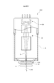
- the schematic diagram which shows the X-ray tube and X-ray analyzer which concern on 1st Embodiment of this invention.
- the typical cross-sectional enlarged view which expanded the front-end
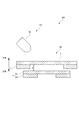
- the typical cross-sectional enlarged view which shows the structure of the X-ray permeable film and target mechanism in case the X-ray tube which concerns on 1st Embodiment is not evacuated.
- the typical cross-sectional enlarged view which shows the structure of the X-ray permeable film and target mechanism in case the vacuum of the X-ray tube which concerns on 1st Embodiment is carried out.
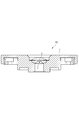
- the typical cross-sectional enlarged view which shows the structure of the X-ray tube which concerns on 2nd Embodiment of this invention.
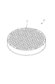
- the typical perspective view which shows the structure of the capillary plate of the X-ray tube which concerns on 2nd Embodiment.
- the typical cross-sectional enlarged view which shows the structure of the X-ray tube in the modification of 2nd Embodiment.
- the X-ray tube 100 and the X-ray analyzer 200 according to the first embodiment of the present invention will be described with reference to FIGS.
- the X-ray tube 100 of the first embodiment is a microfocus X-ray source configured so that the focal diameter of the primary X-ray XR1 is about several ⁇ m.
- the X-ray analysis apparatus 200 of the first embodiment includes the X-ray tube 100, a detector system 101, a control unit 7, a calculation mechanism 8, and a display 9, as shown in FIG. This is an inverted X-ray analyzer 200 configured such that the X-ray tube 100 emits a primary X-ray XR1 vertically upward.
- a sample S to be X-ray analyzed is directly placed on an X-ray transmission window portion formed on the top surface of the X-ray tube 100, and secondary X-ray XR2 generated in the sample S is obtained. Is detected and the sample S is analyzed.
- the X-ray tube 100 is provided as shown in FIG. 1 so as to partition the inside and outside of the vacuum container 1, and an X-ray transmission film 2 that forms an X-ray transmission window; At least the electron beam source 3, the beam optical system 4, and the target mechanism 5 including the target thin film 51 provided inside the vacuum container 1 are provided.
- the sample S and the target are sandwiched between the X-ray transmissive film 2 in a state where the inside is maintained at a predetermined degree of vacuum and the sample X is irradiated with the primary X-ray XR1.
- the thin film 51 is adjacent.
- the vacuum vessel 1 is connected to a vacuum pump 6, and the inside of the vacuum vessel 1 is maintained at a predetermined degree of vacuum when the sample S is irradiated with the primary X-ray XR1. As shown in FIGS. 2 and 3, the vacuum vessel 1 is provided with the X-ray permeable film 2 detachably on the top surface.
- the X-ray permeable membrane 2 has a membrane structure as shown in the enlarged view of FIG. 3, and the inside of the vacuum vessel 1 is not evacuated, and the pressure is approximately the same as the atmospheric pressure.
- the target mechanism 5 is provided as a separate body so as not to contact the target mechanism 5.
- the X-ray transmission film 2 is moved to the inside of the vacuum vessel 1.
- the opposing surface which is the inner surface, is in direct contact with the target mechanism 5. As shown in FIG.
- the sample S when the sample S is, for example, in the form of particles, the sample S can be placed in the recess on the outer surface that is recessed on the outer surface of the X-ray permeable membrane 2.
- the sample S is not limited to a particulate material, and may be a solid or a liquid.
- the X-ray permeable film 2 is made of, for example, polyimide having a predetermined elasticity, and a material that does not have a chemical reaction with the target sample S and has X-ray permeability is selected.
- the electron beam source 3 is configured such that a voltage is applied to the target thin film 51 as an anode, and an electron beam EB is emitted to the target thin film 51.
- the beam optical system 4 is composed of, for example, a plurality of electromagnets as shown in FIG. 1, deflects the electron beam EB emitted from the electron beam source 3, and is irradiated on the target thin film 51 with a diameter of about several ⁇ m. So that the light is condensed.
- the irradiation position of the electron beam EB on the target thin film 51 can be scanned by changing the magnetic field or electric field formed in the beam optical system 4.
- the target mechanism 5 receives the electron beam EB emitted from the electron beam source 3 and emits primary X-rays XR1 in the direction of the X-ray transmission film 2 as shown in FIGS. More specifically, in the first embodiment, the target mechanism 5 separates the target thin film 51 and the target thin film 51 from the X-ray transmission film 2 by a predetermined distance when there is no pressure difference between the inside and outside of the vacuum vessel 1. And a target support 52 for disposing the target thin film 51 at the position.
- the target thin film 51 is a thin film made of a metal such as tungsten, for example, and generates an X-ray XR upon receiving an electron beam EB.
- One surface of the thin film is supported from the inside of the vacuum vessel 1 by the target support 52 so as to face the inner surface of the X-ray permeable membrane 2.
- This target thin film 51 is also configured to be replaceable when it deteriorates.
- the target support 52 has a substantially circular opening that reaches the target thin film 51 when the electron beam EB is incident on the center thereof. This opening is formed coaxially smaller than the opening in which the X-ray transmission film 2 is provided in the vacuum vessel 1.
- the separation distance d between the target thin film 51 and the X-ray transmission film 2 shown in FIG. 3 when there is no pressure difference inside and outside the vacuum vessel 1 will be described.
- the X-ray permeable membrane 2 bends inwardly due to an evenly distributed load due to a pressure difference between the inside and outside.
- the maximum displacement amount on the target thin film 51 side of the X-ray transmission film 2 and the separation distance d are set to be substantially the same value. That is, as shown in FIG. 4, even when the X-ray transmissive film 2 is deformed due to a pressure difference, the X-ray transmissive film 2 only touches the target thin film 51 and presses against the target thin film 51.
- the load is hardly applied. Therefore, in any state shown in FIGS. 3 and 4, the target thin film 51 is maintained in substantially the same shape, and is configured so as to hardly deform. Further, as shown in FIG. 4, the flat portion on the inner side surface of the X-ray transmissive film 2 after deformation substantially coincides with the opening portion of the target support 52. Therefore, even if the electron beam EB is irradiated on any part of the target thin film 51, the primary X-ray XR1 is incident on the X-ray transmission film 2 in substantially the same state.
- the detector system 101 includes a first X-ray detector D1 provided along the axial direction, and the axial direction.
- a second X-ray detector D2 provided obliquely and an optical microscope provided so that the outer surface of the X-ray transmission film 2 is captured in the field of view.
- the second X-ray detector D2 is provided obliquely with respect to the traveling direction of the main primary X-ray XR1, and can mainly detect fluorescent X-rays that are the secondary X-ray XR2 excited in the sample S. is there. Even in the second X-ray detector D2 provided in this way, some of the primary X-rays XR1 generated in the target thin film 51 that travel obliquely with respect to the axial direction are incident.
- the detector system 101 detects the fluorescent X-rays excited by the sample S as the secondary X-ray XR2.
- the detector system 101 detects other types of secondary X-rays XR2. May be.
- the secondary X-ray XR2 detected by the detector system 101 may be a scattered X-ray in which the primary X-ray XR1 is scattered in the sample S or a transmitted X-ray in which the primary X-ray XR1 is transmitted through the sample S. .
- the control unit 7 controls the operation of the X-ray tube 100, the vacuum pump 6, the detector system 101, and the arithmetic mechanism 8.
- the arithmetic mechanism 8 is a computer including, for example, a CPU, a memory, an A / D / D / A converter, an input / output means, and the like so that the X-ray analyzer program stored in the memory is executed. It is configured.
- the calculation mechanism 8 exhibits at least functions as a signal processing unit 81, an analysis unit 82, and an imaging unit 83 by executing programs and cooperation of various devices.
- the signal processing unit 81 generates a spectrum of the secondary X-ray XR2 generated from the sample S based on, for example, the output of the first X-ray detector D1 or the second X-ray detector D2.
- the analysis unit 82 performs qualitative analysis or quantitative analysis of the sample S based on the spectrum of the secondary X-ray XR2 generated in the signal processing unit. For example, the analysis unit 82 specifies the composition of the sample S from the wavelength of fluorescent X-rays generated from the sample S, and specifies the ratio of the constituent substances from the intensity.
- the imaging unit 83 provides information on the position where the X-ray is irradiated in the sample S obtained by the optical microscope MS, and the qualitative analysis of the element output by the analysis unit 82 regarding the position irradiated with the X-ray. Based on the result or the quantitative analysis result, image data is generated by mapping the element distribution for each position of the sample S and displayed on the display unit 9.
- the pressure in the vacuum vessel 1 is a predetermined pressure, and the primary X-ray XR1 is irradiated to the sample S.
- the resolution and brightness of the X-ray transmission image of the sample S obtained based on the output from the detector system 101 can be set to the highest state.
- the X-ray permeable membrane 2 and the target mechanism 5 are provided separately from each other, the load generated when there is a pressure difference inside and outside the vacuum vessel 1 is borne only by the X-ray permeable membrane 2.
- the target thin film 51 can be hardly loaded. For this reason, the target thin film 51 is plastically deformed, for example, is dented toward the electron beam source 3, and a gap is generated between the X-ray transmission film 2 and the target thin film 51, so that the sample S and the target thin film 51 It is possible to prevent the distance between them from changing from the design value in the direction of increasing.
- the target thin film 51 Even if the pressure in the vacuum vessel 1 repeatedly fluctuates between atmospheric pressure and a predetermined degree of vacuum, for example, due to maintenance or the like, the target thin film 51 hardly fluctuates in load. It is difficult to cause deterioration and destruction due to the above, and the life as the target thin film 51 can be improved as compared with the conventional case.
- the target thin film and the sample are tried to be as close as possible in the conventional X-ray tube, the target is caused by the pressure difference between the inside and outside of the vacuum vessel. A large deformation occurs in the thin film, which can solve the problem that the resolution and brightness of the captured image based on, for example, X-rays are impaired.
- the target thin film 51 is close to the sample S through the X-ray transmissive film 2, the sample S does not come into direct contact with the target thin film 51. Therefore, even when the sample S and the metal forming the target thin film 51 have high chemical activity, the target thin film 51 can be prevented from being deteriorated by a chemical reaction.
- the X-ray tube 100 of the second embodiment is different from the X-ray tube 100 of the first embodiment in the configuration of the X-ray permeable membrane 2 and the target mechanism 5.
- the target mechanism 5 of the second embodiment is configured so that the target thin film 51 made of metal and the target thin film 51 are located at a predetermined distance from the X-ray transmission film 2 when there is no pressure difference between the inside and outside of the vacuum vessel 1. Between the X-ray transmission film 2 and the target thin film 51, and an intermediate body 53 that regulates the traveling direction of the X-ray XR generated in the target thin film 51 in a predetermined direction. And.
- the interposer 53 is a capillary plate in which a large number of capillaries C are formed so as to penetrate both face plate portions in the axial direction of a disk-shaped lead glass.
- the inclusions 53 are placed on the target thin film 51 so that each capillary C is perpendicular to the face plate portion of the target thin film 51.
- the interposer 53 is not fixed to the vacuum vessel 1 or the X-ray permeable membrane 2 by adhesion or the like, and is provided as a separate body from each constituent member.
- the amount of deformation of the X-ray transmission film 2 is smaller than the amount of deformation of the first embodiment.
- the dimension and rigidity of the membrane 2 are set.
- the X-ray permeable membrane 2 is in contact with the outer surface of the interposer 53 in a state of being bent and deformed, and generates little load on the interposer 53 and the target thin film 51. is there.
- the traveling direction of the X-ray XR generated in the target thin film 51 by the inclusion 53 can be limited only to the axial direction in which the capillary extends. . Therefore, the primary X-ray XR1 traveling in an oblique direction with respect to the axial direction as shown in FIG. 4 is prevented from directly entering the second X-ray detector D2, and only the secondary X-ray XR2 derived from the sample S is prevented. Imaging can be performed. Therefore, in the second detector D2, it is possible to prevent background noise from increasing due to the incidence of the primary X-ray XR1, and the output from being easily saturated. For this reason, the detection range and resolution of the secondary X-ray XR2 can be increased, and precise analysis becomes possible.
- the X-ray tube 100 of the second embodiment does not generate a load on the target thin film 51 even when there is a pressure difference between the inside and the outside of the vacuum vessel 1 so as not to be deformed. can do. Therefore, substantially the same effect as the first embodiment can be obtained.
- the interposition body 53 having the same separation distance between the X-ray transmission film 2 and the target thin film 51 is provided.
- an interposition body having a smaller thickness may be provided. Good.
- the X-ray permeable film 2 is bent inward so as to come close to or come into contact with the upper side surface of the interposition body 53. It may be configured.
- the X-ray permeable film is not limited to polyimide, and may be a resin film having X-ray permeability and not chemically reactive with the sample.
- the X-ray permeable film may be a Mylar film or the like.
- the target thin film is not limited to tungsten, and may be copper, molybdenum, cobalt, chromium, iron, silver, or the like.
- the X-ray analyzer may be any apparatus that irradiates a sample with X-rays and analyzes the sample based on scattered X-rays, fluorescent X-rays, transmitted X-rays, and the like obtained from the sample.
- the inclusion is not limited to the capillary plate, and may be silicon nitride (silicon nitride) or the like.
- the X-ray permeable membrane may be configured so that its position can be changed with respect to the target thin film. That is, the top surface portion of the vacuum vessel may be configured as a stage that can move with respect to the face plate direction of the target thin film while supporting the X-ray transmission film, for example. In this way, when the sample is very small and the X-rays emitted from the target thin film do not enter well, the position can be changed so that the X-rays are irradiated.
- the X-ray permeable membrane may be configured to be slightly separated from and close to the target mechanism when the inside of the vacuum vessel reaches a predetermined degree of vacuum.
- the X-ray permeable film may be separated from the target thin film when the inside of the vacuum vessel reaches a predetermined degree of vacuum. What is necessary is just to make it the separation distance of the said X-ray permeable film and the said target thin film be 1 mm or less, for example when the inside of the said vacuum vessel becomes a predetermined degree of vacuum.
- the distance between the target mechanism and the X-ray transmission film may be equal to or less than the film thickness of the X-ray transmission film.
- the distance between the sample and the target mechanism can be optimized at the time of X-ray irradiation. For example, the resolution, brightness, etc. of an X-ray transmission image of the sample can be reduced. It becomes possible to improve.
Landscapes
- Physics & Mathematics (AREA)
- Health & Medical Sciences (AREA)
- Life Sciences & Earth Sciences (AREA)
- Chemical & Material Sciences (AREA)
- Analytical Chemistry (AREA)
- Biochemistry (AREA)
- General Health & Medical Sciences (AREA)
- General Physics & Mathematics (AREA)
- Immunology (AREA)
- Pathology (AREA)
- Analysing Materials By The Use Of Radiation (AREA)
Abstract
ターゲットと試料との距離をできる限り小さくしつつ、電子線が照射されてX線を射出するターゲットについては圧力差による変形は生じにくくすることができるX線管、及び、このX線管を用いたX線分析装置を提供するために、真空容器(1)の内部に設けられ、電子線EBを受けてX線XRを射出するターゲット機構(5)と、前記真空容器(1)の内外を仕切るように前記ターゲット機構(5)とは別体として設けられ、当該ターゲット機構5から射出されたX線が透過可能なX線透過膜(2)と、を備え、前記X線透過膜(2)が、前記真空容器(1)の内部が所定の真空度の場合に当該真空容器(1)の内側へたわんで前記ターゲット機構(5)に近接又は接触するように構成した。
Description
本発明は、真空容器内に配置されたターゲットに対して電子線を照射し、前記ターゲットからX線を射出させるように構成されたX線管、及び、X線管を用いたX線分析装置に関するものである。
X線管100Aは、図8に示すように真空容器1A内に設けられた陰極3Aから発生させた電子線Eを陽極となるターゲット薄膜51Aに対して照射して、当該ターゲット薄膜51AからX線XRを発生させるように構成されている。
より具体的には図7及び特許文献1に示されるX線管100Aは、内部が所定の真空度に保たれる真空容器1Aと、真空容器1Aの開口部分を防ぐように設けられたダイヤモンド製のX線透過板2Aと、前記X線透過板2Aの内側面に対して一体となるように蒸着されたターゲット薄膜51Aと、前記ターゲット薄膜51Aに対して電子線Eを照射する陰極3Aと、を備えている。このX線管100Aは、電子線EBが前記ターゲット薄膜51A上に微小な像を結ぶように構成された、いわゆるマイクロフォーカスX線管である。
このように構成されたX線管100Aを用いて例えばX線透視画像を撮像する場合、X線が発生する前記ターゲット薄膜51Aに撮像対象となる試料Sをできるだけ近づけたほうが、得られる撮像画像の解像度や輝度を向上させることができる。したがって、前記ターゲット薄膜51Aは、X線透過窓の近傍に設けて試料との距離を小さくするように配置される。
しかしながら、例えば大気圧中に前記試料Sが配置されている場合には前記X線管100Aの内外において圧力差があるため、前記X線透過窓板2Aは前記真空容器1Aの内側へ凹むようにたわんでしまう。この際、前記X線透過窓板2Aと一体に形成されている前記ターゲット薄膜51Aも同じよう内側へ凹むようにたわんでしまう。
ここで、前記ターゲット薄膜51Aの変位量が大きく塑性変形が生じている場合にはターゲット薄膜51Aと試料Sとの間の距離は設計上の距離よりも大きい状態が維持されてしまい、X線透過画像の解像度が常に低下する原因となる。
また、前記ターゲット薄膜51Aに弾性変形が生じている場合でもメンテナンス等のために前記X線管100A内は大気開放されるため、前記ターゲット薄膜51Aには変形と復元による繰り返し応力が発生し、前記ターゲット薄膜51Aが早期に劣化又は破壊されてしまう恐れがある。
本発明は上述したような問題を鑑みてなされたものであり、試料とターゲットとの間の離間距離を最適化することができ、例えばX線に基づく撮像画像の解像度や輝度を高くすることができるX線管、及び、このX線管を用いたX線分析装置を提供することを目的とする。
すなわち、本発明に係るX線管は、真空容器の内部に設けられ、電子線を受けてX線を射出するターゲット機構と、前記真空容器の内外を仕切るように前記ターゲット機構とは別体として設けられ、当該ターゲット機構から射出されたX線が透過可能なX線透過膜と、を備え、前記X線透過膜が、前記真空容器の内部が所定の真空度の場合に当該真空容器の内側へたわんで前記ターゲット機構に近接又は接触するように構成されていることを特徴とする。
このようなものであれば、前記真空容器の内外に圧力差があってもその圧力差に基づく荷重は主に前記X線透過膜で負担させることができる。また、前記X線透過膜と前記ターゲット機構は別体として構成されているので、前記X線透過膜の変形は前記ターゲット機構に対してほとんど伝達されない。したがって、前記ターゲット機構にほとんど荷重がかからないようにして当該ターゲット機構に変形が生じるのを防ぐことができる。
さらに、前記X線透過膜が、前記真空容器の内部が所定の真空度の場合に当該真空容器の内側へたわんで前記ターゲット機構に近接又は接触するように構成されているので、前記X線透過膜の外側に配置される分析対象の試料と前記ターゲット機構との間の距離を小さくすることができる。しかも、前記ターゲット機構には変形はほとんど生じないので、前記試料と前記ターゲット機構との間の距離は設計上の値でほぼ保つことができる。
また、前記ターゲット機構には変形がほとんど生じないので変形と復元が繰り返されることによる繰り返し荷重も小さく、前記ターゲット機構を長寿命にすることができる。
試料とX線の発生源である前記ターゲット機構との間の距離を短くすることができ、例えば試料のX線撮像画像の解像度や輝度を従来よりも向上させることができるようにするには、前記X線透過膜の外側面が、X線の照射対象である試料が載置される試料載置面であり、前記X線透過膜の内側面が、前記ターゲット機構と近接又は接触する対向面であればよい。
試料と前記ターゲット機構において実際にX線が発生している箇所との間の距離を前記X線透過膜の厚み程度にすることができ、試料のX線撮像画像における解像度や輝度をさらに向上させられるようにするには、前記ターゲット機構が、金属からなるターゲット薄膜と、前記真空容器の内外の圧力差が無い場合に前記X線透過膜から所定距離離間した位置に前記ターゲット薄膜を配置するターゲット支持体と、を備えたものであればよい。
前記真空容器の内外の圧力差による前記ターゲット薄膜の変形を最小限に抑えつつ、試料と前記ターゲット薄膜との距離を最も近づけられるようにするには、前記真空容器の内外の圧力が無い場合における前記X線透過膜と前記ターゲット薄膜との間の離間距離が、前記真空容器の内部が所定の真空度の場合に前記X線透過膜に生じる前記ターゲット薄膜側への変形量とほぼ同じ値に設定されていればよい。
前記ターゲット薄膜から射出されるX線の進行方向を所定の方向に限定し、前記ターゲット薄膜で発生した一次X線が多量に検出器に入射することを防ぎ、例えば試料で発生した二次X線のみを検出しやすくして、試料のX線透過画像をより鮮明しつつ、前記ターゲット薄膜の変形は抑えられるようにするには、前記ターゲット機構が、金属からなるターゲット薄膜と、前記真空容器の内外の圧力差が無い場合に前記X線透過膜から所定距離離間した位置に前記ターゲット薄膜を配置するターゲット支持体と、前記X線透過膜と、前記ターゲット薄膜との間に設けられ、前記ターゲット薄膜で発生したX線の進行方向を所定方向に規制する介在体と、を備え、前記X線透過膜が、前記真空容器の内部が所定の真空度の場合に前記介在体と接触するように構成されていればよい。
前記ターゲット薄膜が前記試料に対して直接接触しないようにしてターゲット薄膜の試料との化学的反応による劣化を防ぐことができるようにするには、前記X線透過膜が、ポリイミドで形成された弾性膜であればよい。
前記ターゲット機構からX線が射出される全域に対して前記X線透過膜が平面状に接触させるには、前記X線透過膜において前記真空容器の内側へ変形する領域の面積が、前記ターゲット機構に対して電子線が入射する面積よりも大きいものであればよい。
前記X線透過膜上に配置されている試料が微小であっても、前記ターゲット機構から射出されるX線に対して試料を適切な位置に配置することを容易にし、より鮮明なX線撮像画像等を得られるようにするには、前記X線透過膜が、移動可能に設けられていればよい。
本発明に係るX線管と、試料から発生したX線を検出するX線検出器と、前記検出器の出力に基づいて、X線のスペクトルを生成する信号処理部と、前記信号処理部において生成されたX線のスペクトルに基づいて、試料の定性分析又は定量分析を行う分析部と、を備えたX線分析装置であれば、前記ターゲット機構におけるX線の発生位置と撮像対象の試料との位置を近づけ、解像度や輝度の高い画像を得ることができる。
X線に基づいて試料の各位置におけるより詳細な分析を可能とするには、前記X線透過膜上の外側面を視野内に捉えるように設けられた光学顕微鏡と、試料の各位置における元素分布をマッピングした画像データを生成するイメージング部と、をさらに備えたものであればよい。
このように本発明に係るX線管によれば、X線の照射時において前記試料と前記ターゲット機構との離間距離を最適化することができ、例えば試料のX線透過画像等においてその解像度や輝度等を向上させることが可能となる。
200・・・X線分析装置
100・・・X線管
101・・・検出器系
D2 ・・・第2X線検出器
1 ・・・真空容器
2 ・・・X線透過膜
3 ・・・電子線源
4 ・・・ビーム光学系
5 ・・・ターゲット機構
51 ・・・ターゲット薄膜
52 ・・・ターゲット支持体
53 ・・・介在体
81 ・・・信号処理部
82 ・・・分析部
83 ・・・イメージング部
MS ・・・光学顕微鏡
100・・・X線管
101・・・検出器系
D2 ・・・第2X線検出器
1 ・・・真空容器
2 ・・・X線透過膜
3 ・・・電子線源
4 ・・・ビーム光学系
5 ・・・ターゲット機構
51 ・・・ターゲット薄膜
52 ・・・ターゲット支持体
53 ・・・介在体
81 ・・・信号処理部
82 ・・・分析部
83 ・・・イメージング部
MS ・・・光学顕微鏡
本発明の第1実施形態に係るX線管100、及び、X線分析装置200について図1乃至図4を参照しながら説明する。第1実施形態のX線管100は、一次X線XR1の焦点径が数μm程度となるように構成されたマイクロフォーカスX線源である。また、第1実施形態のX線分析装置200は、図1に示すように前記X線管100と、検出器系101と、制御部7と、演算機構8と、表示器9とからなり、前記X線管100が鉛直上向きに一次X線XR1を射出するように構成した倒立型のX線分析装置200である。このX線分析装置200では、前記X線管100の天面に形成したX線透過窓部分にX線分析対象となる試料Sが直接載置され、当該試料Sにおいて発生した二次X線XR2を検出して試料Sの分析を行うようにしてある。
より具体的に前記X線管100は、図1に示すように真空容器1と、前記真空容器1の内外を仕切るように設けてあり、X線透過窓を形成するX線透過膜2と、前記真空容器1の内部に設けられた電子線源3、ビーム光学系4、及び、前記ターゲット薄膜51を含むターゲット機構5と、を少なくとも備えているものである。第1実施形態の前記X線管100は、内部が所定の真空度に保たれて一次X線XR1が試料Sに照射される状態では、前記X線透過膜2を挟んで試料Sと前記ターゲット薄膜51とが隣接するようにしてある。
前記真空容器1は、真空ポンプ6と接続してあり、この真空容器1の内部は試料Sへ一次X線XR1を照射する際には所定の真空度に保たれるようにしてある。この真空容器1は図2及び3に示すようにその天面部には、前記X線透過膜2が着脱可能に設けてある。
前記X線透過膜2は、図3の拡大図に示すようにメンブレン構造をなすものであり、前記真空容器1の内部が真空引きされておらず、大気圧とほぼ同じ圧力の場合には前記ターゲット機構5と接触しないように当該ターゲット機構5とは別体として設けてある。一方、図4の拡大図に示すように前記真空容器1の内部が真空引きされて所定の真空度に保たれている場合には、前記X線透過膜2は前記真空容器1の内部側へと凹むように変形してその内側面である対向面が前記ターゲット機構5に対して直接接触するようにしてある。図4に示すように前記X線透過膜2の外側面において窪んでいる外側面には例えば試料Sが粒子状のものの場合にはそのくぼみ内に試料Sが配置できるようにしてある。なお、試料Sは粒子状のものに限られず、固体や液体であっても構わない。このX線透過膜2は例えば所定の弾性を有したポリイミドで形成してあり、対象となる試料Sと化学的な反応を有さないとともに、X線透過性を有するものが選択してある。
前記電子線源3は、図1に示すように前記ターゲット薄膜51に対して陽極となるように電圧が印加され、前記ターゲット薄膜51に対して電子線EBを射出するように構成してある。
前記ビーム光学系4は、図1に示すように例えば複数の電磁石からなり、前記電子線源3から射出される電子線EBを偏向させ、前記ターゲット薄膜51上で数μm程度の直径で照射されるように集光するよう構成してある。また、前記ビーム光学系4において形成する磁場又は電場を変化させることにより前記ターゲット薄膜51上の電子線EBの照射位置を走査できるようにしてある。
前記ターゲット機構5は、図2乃至図4に示すように前記電子線源3から射出された電子線EBを受けて一次X線XR1を前記X線透過膜2の方向へ射出するものである。より具体的には第1実施形態では前記ターゲット機構5は、前記ターゲット薄膜51と、前記ターゲット薄膜51を前記真空容器1の内外の圧力差が無い場合に前記X線透過膜2から所定距離離間した位置に前記ターゲット薄膜51を配置するターゲット支持体52と、を備えている。
前記ターゲット薄膜51は、例えばタングステン等の金属からなる薄膜であり、電子線EBを受けてX線XRを発生させるものである。この薄膜の一方の面は前記X線透過膜2の内側面と対向するように前記ターゲット支持体52により前記真空容器1の内部から支持してある。このターゲット薄膜51も劣化時には交換可能に構成してある。前記ターゲット支持体52は中央部に電子線EBが入射して前記ターゲット薄膜51へと至る概略円形状の開口を有している。この開口は前記真空容器1において前記X線透過膜2が設けてある開口よりも小さく同軸上に形成してある。
前記真空容器1の内外に圧力差がない場合における図3に示される前記ターゲット薄膜51と前記X線透過膜2との離間距離dについて説明する。図4に示されるように前記真空容器1の内部が所定の真空度となると、内外の圧力差による等分布荷重により前記X線透過膜2は内側へ凹むようにたわむ。この前記X線透過膜2の前記ターゲット薄膜51側の最大変位量と前記離間距離dはほぼ同じ値になるように設定してある。すなわち、図4に示すように前記X線透過膜2が圧力差により変形した場合でも前記X線透過膜2は前記ターゲット薄膜51に対して接触するだけであり、前記ターゲット薄膜51に対して押圧して荷重をほとんど与えないように構成してある。したがって、図3及び図4に示されるいずれの状態においても前記ターゲット薄膜51はほぼ同じ形状で保たれており、変形もほとんど生じないように構成してある。また、図4に示されるように変形後の前記X線透過膜2の内側面において平坦部分が前記ターゲット支持体52の開口部分とほぼ一致するようにしてある。したがって、前記ターゲット薄膜51のいずれの部分で電子線EBが照射されたとしても前記X線透過膜2に対してほぼ同じ状態で一次X線XR1が入射するようにしてある。
前記検出器系101は、前記ターゲット薄膜51の面板部に対して垂直な方向を軸方向と定義した場合、この軸方向に沿って設けられた第1X線検出器D1と、前記軸方向に対して斜めに傾けて設けられた第2X線検出器D2と、前記X線透過膜2の外側面を視野内に捉えるように設けられた光学顕微鏡と、を備えたものである。前記第2X線検出器D2は、主要な一次X線XR1の進行方向に対して斜めに設けてあり、試料Sにおいて励起された二次X線XR2である蛍光X線を主として検出できるようにしてある。なお、このように設けられた第2X線検出器D2であっても、前記ターゲット薄膜51で発生する一次X線XR1のうち軸方向に対して斜めに進行するものについては一部入射する。
なお、本実施形態では前記検出器系101は、二次X線XR2として試料Sで励起された蛍光X線を検出するものであるが、その他の種類の二次X線XR2を検出するようにしてもよい。例えば前記検出器系101が検出する二次X線XR2は、試料Sにおいて一次X線XR1が散乱された散乱X線や、一次X線XR1が試料Sを透過した透過X線であってもよい。
前記制御部7は、前記X線管100、前記真空ポンプ6、前記検出器系101、前記演算機構8の動作を制御するものである。
前記演算機構8は、例えばCPU、メモリ、A/D・D/Aコンバータ、入出力手段等を備えたコンピュータであって、前記メモリに格納されているX線分析装置用プログラムが実行されるように構成してある。そして、前記演算機構8は、プログラムが実行されて各種機器が協業することにより、少なくとも信号処理部81、分析部82、イメージング部83としての機能を発揮する。
前記信号処理部81は、例えば前記第1X線検出器D1又は前記第2X線検出器D2の出力に基づいて、試料Sから発生した二次X線XR2のスペクトルを生成するものである。
前記分析部82は、前記信号処理部において生成された二次X線XR2のスペクトルに基づいて、試料Sの定性分析又は定量分析を行うものである。例えば前記分析部82は、試料Sから発生する蛍光X線の波長から試料Sの組成を特定し、その強度から構成物質の比率を特定する。
前記イメージング部83は、前記光学顕微鏡MSにより得られる試料SにおいてX線が照射されている位置に関する情報と、そのX線が照射されている位置について前記分析部82により出力される元素の定性分析結果又は定量分析結果に基づいて、試料Sの各位置について元素分布をマッピングした画像データとして生成して前記表示器9に対しては表示するものである。
このように構成されたX線管100、及び、X線分析装置200によれば、前記真空容器1内の圧力が所定の圧力であり、一次X線XR1が試料Sに対して照射される場合には、図4に示すように試料Sをターゲット薄膜51に対して前記X線透過膜2の厚み分だけしか離間させずに近接させて配置することが可能となる。したがって、前記検出器系101からの出力に基づいて得られる試料SのX線透過画像の解像度や輝度を原理的に最も高い状態にすることができる。しかも、前記X線透過膜2と前記ターゲット機構5がそれぞれ別体として設けてあるので、前記真空容器1の内外で圧力差がある場合に発生する荷重は前記X線透過膜2のみで負担され、前記ターゲット薄膜51に対しては荷重がほとんど発生しないようにできる。このため、前記ターゲット薄膜51が例えば塑性変形を起こし、前記電子線源3側へと凹み前記X線透過膜2と前記ターゲット薄膜51との間に隙間が生じて試料Sと前記ターゲット薄膜51との間の距離が設計値から大きくなる方向へ変化するのを防ぐことができる。また、前記真空容器1内の圧力が例えばメンテナンス等により大気圧と所定の真空度との間を繰り返し変動していたとしても、前記ターゲット薄膜51には荷重の変動はほとんど生じないので、繰り返し荷重による劣化や破壊が生じにくく、ターゲット薄膜51としての寿命も従来よりも向上させることができる。
以上のように第1実施形態のX線管100及びX線分析装置200であれば、従来のX線管においてはターゲット薄膜と試料をできるだけ近づけようとしたために真空容器の内外の圧力差によってターゲット薄膜に大きな変形が生じ、それが原因となって例えばX線に基づく撮像画像の解像度や輝度が損なわれていた問題を解決することができる。
加えて、前記ターゲット薄膜51は前記X線透過膜2を介して試料Sと近接するので、試料Sはターゲット薄膜51に対して直接接触することはない。したがって、試料Sとターゲット薄膜51を形成する金属とが化学的活性が高い場合でも、ターゲット薄膜51の化学反応による劣化を防ぐことができる。
次に第2実施形態に係るX線管100について図5及び6を参照しながら説明する。なお、第1実施形態において説明した部材に対応する部材については同じ符号を付すこととする。
第2実施形態のX線管100は、第1実施形態のX線管100と比較してX線透過膜2と、ターゲット機構5の構成が異なっている。
すなわち、第2実施形態のターゲット機構5は、金属からなるターゲット薄膜51と、前記真空容器1の内外の圧力差が無い場合に前記X線透過膜2から所定距離離間した位置に前記ターゲット薄膜51を配置するターゲット支持体52と、前記X線透過膜2と、前記ターゲット薄膜51との間に設けられ、前記ターゲット薄膜51で発生したX線XRの進行方向を所定方向に規制する介在体53と、を備えている。
前記介在体53について図6を参照しながら説明する。この介在体53は円板状の鉛ガラスについて両方の面板部を軸方向に貫通するように多数のキャピラリーCが形成されたキャピラリープレートである。そして、各キャピラリーCが前記ターゲット薄膜51の面板部に対して垂直となるように前記介在体53は当該ターゲット薄膜51上に載置してある。また、前記介在体53は前記真空容器1又は前記X線透過膜2のいずれとも接着等により固定はされておらず、各構成部材と別体として設けてある。
前記真空容器1内が所定の真空度となった場合において、第2実施形態では前記X線透過膜2の変形量は第1実施形態の変形量と比較して小さくなるように前記X線透過膜2の寸法や剛性が設定してある。そして、前記X線透過膜2は内側にたわんで変形した状態で前記介在体53の外側面と接触するとともに、前記介在体53及び前記ターゲット薄膜51に対してはほとんど荷重を発生させないようにしてある。
このように構成された第2実施形態のX線管100であれば、前記介在体53により前記ターゲット薄膜51で発生したX線XRの進行方向をキャピラリーの延びる軸方向のみに限定することができる。したがって、図4において示されるような軸方向に対して斜め方向に進行する一次X線XR1が直接第2X線検出器D2に入射するのを防ぎ、試料Sに由来する二次X線XR2のみの撮像が可能となる。したがって、第2検出器D2においては、一次X線XR1が入射することによりバックグラウンドのノイズが大きくなり、出力が飽和しやすくなるのを防ぐことができる。このため、二次X線XR2の検出レンジや解像度をより大きくすることができ、精密な分析が可能となる。
また、第2実施形態のX線管100も第1実施形態と同様に前記真空容器1の内外に圧力差がある場合でも前記ターゲット薄膜51にはほぼ荷重が発生せず変形を生じないようにすることができる。したがって、第1実施形態とほぼ同じ効果を奏し得る。
次に第2実施形態の変形例について図7を参照しながら説明する。前述した第2第2実施形態では、前記X線透過膜2と前記ターゲット薄膜51との離間距離がほぼ同じ厚みの前記介在体53を設けていたが、より厚みの小さい介在体を設けてもよい。この場合、図7に示すように前記真空容器1内が所定の真空度となった場合に、前記X線透過膜2が内側へたわんで前記介在体53の上側面と近接又は接触するように構成してもよい。
その他の実施形態について説明する。
前記X線透過膜はポリイミドに限られるものではなく、X線透過性を有するとともに試料に対して化学的な反応性を有さない樹脂膜であってもよい。例えば、前記X線透過膜はマイラー膜等であってもよい。
前記ターゲット薄膜は、タングステンに限られるものではなく、銅、モリブデン、コバルト、クロム、鉄、銀等であっても構わない。
前記X線分析装置は、試料に対してX線を照射し、試料から発生して得られる散乱X線や蛍光X線、透過X線等に基づいて試料の分析を行うものであればよい。
前記介在体は、キャピラリープレートに限られるものではなく、窒化珪素(シリコンナイトライド)等であっても構わない。
前記X線透過膜は、前記ターゲット薄膜に対してその位置を変更可能に構成してもよい。すなわち、前記真空容器において天面部を例えば前記X線透過膜を支持しつつ、前記ターゲット薄膜の面板方向に対して移動可能なステージとして構成してもよい。このようにすれば、試料が非常に微小であり、ターゲット薄膜から射出されるX線がうまく入射しない場合には、その位置を変更してX線が照射されるようにすることができる。
前記X線透過膜は、前記真空容器内が所定の真空度となった場合に前記ターゲット機構に対してわずかに離間して近接するように構成してもよい。例えばマイクロフォーカスX線管として求められる精度を実現できる程度であれば、前記真空容器内が所定の真空度となった場合に前記X線透過膜を前記ターゲット薄膜に対して離間させてもよい。前記真空容器内が所定の真空度となった場合における前記X線透過膜と前記ターゲット薄膜の離間距離は例えば1mm以下となるようにすればよい。あるいは、ターゲット機構とX線透過膜の距離はX線透過膜の膜厚以下であってもよい。
その他、本発明の趣旨に反しない限りにおいて様々な実施形態の変形や組みあわせを行っても構わない。
本発明に係るX線管であれば、X線の照射時において前記試料と前記ターゲット機構との離間距離を最適化することができ、例えば試料のX線透過画像等においてその解像度や輝度等を向上させることが可能となる。
Claims (10)
- 真空容器の内部に設けられ、電子線を受けてX線を射出するターゲット機構と、
前記真空容器の内外を仕切るように前記ターゲット機構とは別体として設けられ、当該ターゲット機構から射出されたX線が透過可能なX線透過膜と、を備え、
前記X線透過膜が、前記真空容器の内部が所定の真空度の場合に当該真空容器の内側へたわんで前記ターゲット機構に近接又は接触するように構成されていることを特徴とするX線管。 - 前記X線透過膜の外側面が、照射対象である試料が載置される試料載置面であり、
前記X線透過膜の内側面が、前記ターゲット機構と近接又は接触する対向面である請求項1記載のX線管。 - 前記ターゲット機構が、
金属からなるターゲット薄膜と、
前記真空容器の内外の圧力差が無い場合に前記X線透過膜から所定距離離間した位置に前記ターゲット薄膜を配置するターゲット支持体と、を備え、
前記X線透過膜が、前記真空容器の内部が所定の真空度の場合に前記ターゲット薄膜と近接又は接触するように構成されている請求項1記載のX線管。 - 前記真空容器の内外の圧力が無い場合における前記X線透過膜と前記ターゲット薄膜との間の離間距離が、前記真空容器の内部が所定の真空度の場合に前記X線透過膜に生じる前記ターゲット薄膜側への変形量とほぼ同じ値に設定されている請求項3記載のX線管。
- 前記ターゲット機構が、
金属からなるターゲット薄膜と、
前記真空容器の内外の圧力差が無い場合に前記X線透過膜から所定距離離間した位置に前記ターゲット薄膜を配置するターゲット支持体と、
前記X線透過膜と、前記ターゲット薄膜との間に設けられ、前記ターゲット薄膜で発生したX線の進行方向を所定方向に規制する介在体と、を備え、
前記X線透過膜が、前記真空容器の内部が所定の真空度の場合に前記介在体と近接又は接触するように構成されている請求項1記載のX線管。 - 前記X線透過膜が、ポリイミドで形成された弾性膜である請求項1に記載のX線管。
- 前記X線透過膜において前記真空容器の内側へ変形する領域の面積が、前記ターゲット機構に対して電子線が入射する面積よりも大きい請求項1に記載のX線管。
- 前記X線透過膜が、移動可能に設けられている請求項1に記載のX線管。
- 請求項1に記載のX線管と、
試料から発生したX線を検出するX線検出器と、
前記検出器の出力に基づいて、X線のスペクトルを生成する信号処理部と、
前記信号処理部において生成されたX線のスペクトルに基づいて、試料の定性分析又は定量分析を行う分析部と、を備えたX線分析装置。 - 前記X線透過膜上の外側面を視野内に捉えるように設けられた光学顕微鏡と、
試料の各位置における元素分布をマッピングした画像データを生成するイメージング部と、をさらに備えた請求項9記載のX線分析装置。
Priority Applications (1)
| Application Number | Priority Date | Filing Date | Title |
|---|---|---|---|
| JP2017556068A JP6630365B2 (ja) | 2015-12-15 | 2016-12-13 | X線管、及び、x線分析装置 |
Applications Claiming Priority (2)
| Application Number | Priority Date | Filing Date | Title |
|---|---|---|---|
| JP2015-244617 | 2015-12-15 | ||
| JP2015244617 | 2015-12-15 |
Publications (1)
| Publication Number | Publication Date |
|---|---|
| WO2017104659A1 true WO2017104659A1 (ja) | 2017-06-22 |
Family
ID=59056743
Family Applications (1)
| Application Number | Title | Priority Date | Filing Date |
|---|---|---|---|
| PCT/JP2016/087055 Ceased WO2017104659A1 (ja) | 2015-12-15 | 2016-12-13 | X線管、及び、x線分析装置 |
Country Status (2)
| Country | Link |
|---|---|
| JP (1) | JP6630365B2 (ja) |
| WO (1) | WO2017104659A1 (ja) |
Cited By (3)
| Publication number | Priority date | Publication date | Assignee | Title |
|---|---|---|---|---|
| CN109827982A (zh) * | 2017-11-23 | 2019-05-31 | 核工业西南物理研究院 | 一种土壤重金属检测的快速检测仪 |
| WO2023145236A1 (ja) * | 2022-01-31 | 2023-08-03 | キヤノンアネルバ株式会社 | 異物検出および蛍光x線による同定装置 |
| WO2025005137A1 (ja) * | 2023-06-30 | 2025-01-02 | 株式会社堀場製作所 | 分析装置、分析方法、及び、プログラム |
Citations (3)
| Publication number | Priority date | Publication date | Assignee | Title |
|---|---|---|---|---|
| JPS5461494A (en) * | 1977-10-07 | 1979-05-17 | Machlett Lab Inc | Xxray tube |
| JP2001266781A (ja) * | 2000-03-21 | 2001-09-28 | Toshiba Corp | 放射線透過窓構体およびその製造方法 |
| JP2011209118A (ja) * | 2010-03-30 | 2011-10-20 | Jeol Ltd | X線顕微鏡及びx線を用いた顕微方法。 |
-
2016
- 2016-12-13 WO PCT/JP2016/087055 patent/WO2017104659A1/ja not_active Ceased
- 2016-12-13 JP JP2017556068A patent/JP6630365B2/ja active Active
Patent Citations (3)
| Publication number | Priority date | Publication date | Assignee | Title |
|---|---|---|---|---|
| JPS5461494A (en) * | 1977-10-07 | 1979-05-17 | Machlett Lab Inc | Xxray tube |
| JP2001266781A (ja) * | 2000-03-21 | 2001-09-28 | Toshiba Corp | 放射線透過窓構体およびその製造方法 |
| JP2011209118A (ja) * | 2010-03-30 | 2011-10-20 | Jeol Ltd | X線顕微鏡及びx線を用いた顕微方法。 |
Cited By (17)
| Publication number | Priority date | Publication date | Assignee | Title |
|---|---|---|---|---|
| CN109827982A (zh) * | 2017-11-23 | 2019-05-31 | 核工业西南物理研究院 | 一种土壤重金属检测的快速检测仪 |
| CN109827982B (zh) * | 2017-11-23 | 2024-04-26 | 核工业西南物理研究院 | 一种土壤重金属检测的快速检测仪 |
| WO2023145237A1 (ja) * | 2022-01-31 | 2023-08-03 | キヤノンアネルバ株式会社 | 検査装置および検査方法 |
| US11971370B2 (en) | 2022-01-31 | 2024-04-30 | Canon Anelva Corporation | Inspection apparatus and inspection method |
| WO2023145238A1 (ja) * | 2022-01-31 | 2023-08-03 | キヤノンアネルバ株式会社 | 検査装置および検査方法 |
| WO2023145235A1 (ja) * | 2022-01-31 | 2023-08-03 | キヤノンアネルバ株式会社 | 検査装置および検査方法 |
| US11921059B2 (en) | 2022-01-31 | 2024-03-05 | Canon Anelva Corporation | Inspection apparatus and inspection method |
| US11927554B2 (en) | 2022-01-31 | 2024-03-12 | Canon Anelva Corporation | Inspection apparatus and inspection method |
| WO2023145236A1 (ja) * | 2022-01-31 | 2023-08-03 | キヤノンアネルバ株式会社 | 異物検出および蛍光x線による同定装置 |
| WO2023145101A1 (ja) * | 2022-01-31 | 2023-08-03 | キヤノンアネルバ株式会社 | 検査装置および検査方法 |
| US11977038B2 (en) | 2022-01-31 | 2024-05-07 | Canon Anelva Corporation | Inspection apparatus and inspection method |
| TWI845136B (zh) * | 2022-01-31 | 2024-06-11 | 日商佳能安內華股份有限公司 | 檢查裝置以及檢查方法 |
| TWI845135B (zh) * | 2022-01-31 | 2024-06-11 | 日商佳能安內華股份有限公司 | 檢查裝置以及檢查方法 |
| TWI846289B (zh) * | 2022-01-31 | 2024-06-21 | 日商佳能安內華股份有限公司 | 檢查裝置及檢查方法 |
| US12241848B2 (en) | 2022-01-31 | 2025-03-04 | Canon Anelva Corporation | Inspection apparatus and inspection method |
| TWI874900B (zh) * | 2022-01-31 | 2025-03-01 | 日商佳能安內華股份有限公司 | 檢查裝置以及檢查方法 |
| WO2025005137A1 (ja) * | 2023-06-30 | 2025-01-02 | 株式会社堀場製作所 | 分析装置、分析方法、及び、プログラム |
Also Published As
| Publication number | Publication date |
|---|---|
| JPWO2017104659A1 (ja) | 2018-10-04 |
| JP6630365B2 (ja) | 2020-01-15 |
Similar Documents
| Publication | Publication Date | Title |
|---|---|---|
| JP5135602B2 (ja) | X線管及びx線分析装置 | |
| JP4956701B2 (ja) | X線管及びx線分析装置 | |
| US10147511B2 (en) | Radiolucent window, radiation detector and radiation detection apparatus | |
| CN105518821A (zh) | 带电粒子束装置以及试样图像取得方法 | |
| JP6630365B2 (ja) | X線管、及び、x線分析装置 | |
| KR102029869B1 (ko) | 탈착가능한 전자현미경용 시료실 장치 및 이를 포함하는 전자현미경 | |
| CN111684273A (zh) | 试样支撑体、电离法以及质量分析方法 | |
| JP2014240770A (ja) | 放射線検出装置および放射線分析装置 | |
| JP6952055B2 (ja) | 放射線検出装置 | |
| KR20150024720A (ko) | 평판형 엑스선 발생기 및 이를 구비하는 엑스선 영상 시스템 | |
| JP5458472B2 (ja) | X線管 | |
| US9269533B2 (en) | Analysis apparatus and analysis method | |
| JP2019045402A (ja) | 蛍光x線分析装置及び蛍光x線分析方法 | |
| US11348757B2 (en) | Charged particle beam device | |
| JP2010223898A (ja) | 試料分析方法及び試料分析装置 | |
| JP3869995B2 (ja) | コリメーティングx線分光器およびコリメータ | |
| JP3654568B2 (ja) | X線分析装置 | |
| JP6326341B2 (ja) | 試料ホルダー、および電子顕微鏡 | |
| JP4349146B2 (ja) | X線分析装置 | |
| JP2006003109A (ja) | 蛍光x線分析装置 | |
| KR20140142129A (ko) | 전자빔 검사 장치 | |
| JP6754780B2 (ja) | 試料分析装置及び試料分析装置用集光ミラーユニット | |
| JP7072457B2 (ja) | 試料分析装置、電子顕微鏡、及び集光ミラーユニット | |
| US20250231124A1 (en) | Inspection device, inspection element, and inspection method | |
| JP5993356B2 (ja) | 走査型電子顕微鏡 |
Legal Events
| Date | Code | Title | Description |
|---|---|---|---|
| 121 | Ep: the epo has been informed by wipo that ep was designated in this application |
Ref document number: 16875636 Country of ref document: EP Kind code of ref document: A1 |
|
| ENP | Entry into the national phase |
Ref document number: 2017556068 Country of ref document: JP Kind code of ref document: A |
|
| NENP | Non-entry into the national phase |
Ref country code: DE |
|
| 122 | Ep: pct application non-entry in european phase |
Ref document number: 16875636 Country of ref document: EP Kind code of ref document: A1 |