WO2017104628A1 - 車両用ロック装置 - Google Patents
車両用ロック装置 Download PDFInfo
- Publication number
- WO2017104628A1 WO2017104628A1 PCT/JP2016/086961 JP2016086961W WO2017104628A1 WO 2017104628 A1 WO2017104628 A1 WO 2017104628A1 JP 2016086961 W JP2016086961 W JP 2016086961W WO 2017104628 A1 WO2017104628 A1 WO 2017104628A1
- Authority
- WO
- WIPO (PCT)
- Prior art keywords
- latch
- cam
- pole
- shaft portion
- cam member
- Prior art date
- Legal status (The legal status is an assumption and is not a legal conclusion. Google has not performed a legal analysis and makes no representation as to the accuracy of the status listed.)
- Ceased
Links
Images



Classifications
-
- B—PERFORMING OPERATIONS; TRANSPORTING
- B60—VEHICLES IN GENERAL
- B60N—SEATS SPECIALLY ADAPTED FOR VEHICLES; VEHICLE PASSENGER ACCOMMODATION NOT OTHERWISE PROVIDED FOR
- B60N2/00—Seats specially adapted for vehicles; Arrangement or mounting of seats in vehicles
- B60N2/02—Seats specially adapted for vehicles; Arrangement or mounting of seats in vehicles the seat or part thereof being movable, e.g. adjustable
- B60N2/20—Seats specially adapted for vehicles; Arrangement or mounting of seats in vehicles the seat or part thereof being movable, e.g. adjustable the back-rest being tiltable, e.g. to permit easy access
-
- B—PERFORMING OPERATIONS; TRANSPORTING
- B60—VEHICLES IN GENERAL
- B60N—SEATS SPECIALLY ADAPTED FOR VEHICLES; VEHICLE PASSENGER ACCOMMODATION NOT OTHERWISE PROVIDED FOR
- B60N2/00—Seats specially adapted for vehicles; Arrangement or mounting of seats in vehicles
- B60N2/90—Details or parts not otherwise provided for
-
- E—FIXED CONSTRUCTIONS
- E05—LOCKS; KEYS; WINDOW OR DOOR FITTINGS; SAFES
- E05B—LOCKS; ACCESSORIES THEREFOR; HANDCUFFS
- E05B83/00—Vehicle locks specially adapted for particular types of wing or vehicle
-
- E—FIXED CONSTRUCTIONS
- E05—LOCKS; KEYS; WINDOW OR DOOR FITTINGS; SAFES
- E05B—LOCKS; ACCESSORIES THEREFOR; HANDCUFFS
- E05B85/00—Details of vehicle locks not provided for in groups E05B77/00 - E05B83/00
- E05B85/20—Bolts or detents
- E05B85/24—Bolts rotating about an axis
- E05B85/26—Cooperation between bolts and detents
Definitions
- the present invention relates to a vehicle locking device.
- a seat lock device described in Patent Document 1 is known.
- This seat lock device includes a base member having a base groove portion (insertion groove) into which a striker can be inserted, and a latch having a latch groove portion (restraint groove) that can be engaged with and disengaged from the striker.
- the seat lock device holds the locked state by restraining the striker by a base member and a latch and restricting the rotation of the latch by a pawl.
- the pressed portion (embossing protrusion) provided on the latch is pressed by the urging force of the torsion spring by the cam member, so that the latch is rotated in the locking direction and driven, and the rattling in the locked state occurs. Is suppressed.
- the pole and the cam member are arranged so as to overlap each other in the axial direction so as to be coaxial with each other.
- JP 2005-138785 A Japanese Patent Application Laid-Open No. 2012-179962
- the pressing surface of the cam member pressing the latch is closer to the axis of the cam member. This is because, for example, if the torque generated by the torsion spring is constant, the urging force of the torsion spring on the pressing surface increases as it approaches the axis, that is, the urging force of the torsion spring is transmitted to the pressing surface with higher efficiency. This is because it can.
- the cam member is arranged coaxially with the pole. In such a cam member, the position of the axis of the cam member is limited by the relationship between the latch and the pole. Therefore, there is a limit to shortening the distance from the cam member axis to the pressing surface, and it may be difficult to efficiently transmit the urging force of the torsion spring.
- An object of the present invention is to provide a vehicle locking device that can transmit the urging force of a torsion spring to the pressing surface of the cam member more efficiently without increasing the number of parts.
- a vehicle locking device that achieves the above object has a base groove portion into which a striker can be inserted, which is configured to be fixed to one of a fixed member and a movable member, and is fixed to the other of the fixed member and the movable member.
- a base member having a first shaft portion and a second shaft portion that is eccentric with respect to the first shaft portion, and a support shaft that is fixed to the base member so as not to rotate.
- a latch that is rotatably connected and is pivotable between a lock position that restrains the striker with the base groove and an unlock position that releases the striker, and is pivotally supported by the first shaft portion.
- Movable pole A cam member that is pivotally supported by the second shaft portion and that presses the latch at the lock position with a pressing surface to rotate the latch so that the striker contacts the bottom surface of the base groove portion, and the support A torsion spring wound around a shaft and biasing the cam member in a rotational direction in which the cam member presses the latch with the pressing surface, and the axis of the second shaft portion and the pressing surface
- the separation distance is set shorter than the separation distance between the axis of the first shaft portion and the pressing surface.
- the disassembled perspective view which shows the structure about one Embodiment of the locking device for vehicles.
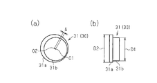
- (A), (b) is the simplification figure which looked at the structure about the pole cam shaft of the locking device for vehicles of the embodiment in the axial direction and the radial direction, respectively.
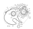
- the schematic diagram which shows the unlocked state about the locking device for vehicles of the embodiment.
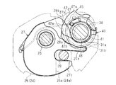
- the schematic diagram which shows the locked state about the locking device for vehicles of the embodiment.
- the perspective view which shows the structure about the rear seat
- a rear seat 10 mounted on the rear side of a vehicle such as an automobile has a seat cushion 11 that forms a seating portion of the occupant and a seat back 12 as a movable member that forms a backrest portion of the occupant.
- the seat back 12 is a movable member that is supported by the rear lower end portion of the seat cushion 11 and is tiltable in the front-rear direction.
- a lock device 21 is installed on the side surface of the seat back 12.
- a vehicle body (not shown) as a fixing member has a substantially U shape made of, for example, a metal rod in accordance with the position of the locking device 21 in a state where the seat back 12 is raised on the rear side (shown by a solid line).
- a character-like striker 20 is fixed.
- One end of the rod-shaped operation lever 22 is linked to the lock device 21, and the other end of the operation lever 22 is exposed from the seat back 12.
- the posture of the seat back 12 is maintained by engaging the striker 20 and the lock device 21.
- the operation lever 22 is pulled, the engagement state of the striker 20 and the lock device 21 is released, and the seat back 12 can be tilted forward with respect to the seat cushion 11 (illustrated by a two-dot chain line).
- the locking device 21 includes a base plate 24 made of, for example, a metal plate, and a substantially box-shaped base housing 25 made of, for example, a resin material.
- the base housing 25 is stacked on the base plate 24 in the thickness direction of the base plate 24.
- the base plate 24 and the base housing 25 constitute a base member that forms a housing of the lock device 21.
- the base plate 24 and the base housing 25 are formed with substantially U-shaped base groove portions 24a and 25a that open so as to face the striker 20 on the movement locus when the seat back 12 is raised to the rear side.
- the striker 20 is inserted into the base groove portions 24a and 25a when the seat back 12 is raised to the rear side, and conversely, the base groove portions 24a and 25a are detached from the striker 20 when the seat back 12 is tilted forward.
- the back side end surfaces that are the deepest portions of the base groove portions 24 a and 25 a become the bottom surfaces 241 a and 251 a that can contact the striker 20.
- a circular fixing hole 24b is formed on the upper left side of the base groove portion 24a in the drawing, and a substantially oval fixing hole 24c is formed on the upper right side of the base groove portion 24a in the drawing.
- a circular fixing hole 25b concentric with the fixing hole 24b is formed, and a substantially oblong fixing hole 25c concentric with the fixing hole 24c is formed.
- the inner diameter of the fixing hole 25b is set larger than the inner diameter of the fixing hole 24b, and the opening width of the fixing hole 25c is set smaller than the opening width of the fixing hole 24c as a whole.
- a latch 27 made of a plate material is rotatably connected to the base plate 24 by a latch shaft 26 made of a metal rod, for example. That is, the latch shaft 26 includes a support portion 26a, a head portion 26b, and an attachment portion 26c.
- the support portion 26a has a substantially cylindrical shape having an outer diameter equivalent to the inner diameter of the fixed hole 25b.
- the head portion 26b is a flange that extends radially outward from one end of the support portion 26a that is separated from the base plate 24.
- the attachment portion 26c has a substantially cylindrical shape that protrudes in the axial direction from the other end of the support portion 26a.
- the outer diameter of the mounting portion 26c is set to be equal to the inner diameter of the fixed hole 24b.
- the latch 27 is formed with a circular insertion hole 27a having an inner diameter equivalent to the outer diameter of the support portion 26a.
- the latch 27 is rotatable around the support portion 26a when the support portion 26a inserted through the fixing hole 25b is inserted through the insertion hole 27a.
- the latch portion 27 is positioned in the axial range sandwiched between the base plate 24 and the base housing 25 by inserting the attachment portion 26c into the fixing hole 24b.
- the latch 27 is formed with a substantially U-shaped latch groove 27b that is recessed toward the center of the latch 27 in the vicinity of the base grooves 24a and 25a.
- the opening width of the latch groove 27b is set to be slightly larger than the diameter of the striker 20 (metal bar).
- the latch 27 includes a first claw-shaped first engaging portion 27c and a substantially lip-shaped second engaging portion 27d.
- the first engaging portion 27c and the second engaging portion 27d form a latch groove portion 27b.
- the first engaging portion 27c is located at a position close to the open ends of the base groove portions 24a and 25a with the latch groove portion 27b as a reference.
- the second engaging portion 27d is located near the bottom surfaces 241a and 251a of the base groove portions 24a and 25a with reference to the latch groove portion 27b.
- the latch 27 has a substantially chevron-shaped contact portion 28 projecting radially outward centered on the insertion hole 27a at an angular position preceding the second engagement portion 27d in the counterclockwise direction in the drawing. Yes.
- An end surface of the abutting portion 28 on the second engaging portion 27d side forms a first latch engaging surface 28a having a substantially arcuate concave shape in the center as a pressed surface.
- the tip end surface connected to the first latch engagement surface 28a of the contact portion 28 forms a second latch engagement surface 28b having a substantially arcuate surface with the insertion hole 27a as the center. That is, the first latch engagement surface 28 a and the second latch engagement surface 28 b are both disposed on the plate thickness surface of the latch 27.
- the “plate thickness surface” means a surface having a much larger area than the other surfaces of the latch 27, that is, a side surface intersecting with a so-called main surface (major surface or back surface) and forming its outer shape. To do.
- the base plate 24 is connected to a pole 40 and a cam member 45, both of which are made of plate material, by a pole cam shaft 30 as a support shaft.
- the pole cam shaft 30 includes a substantially columnar support portion 31 and a stepped substantially disk-shaped flange 32.
- the flange 32 extends radially outward from one end of the support portion 31 away from the base plate 24.
- the pole cam shaft 30 has a fitting portion 33 that protrudes in the axial direction from the central portion of one end of the flange 32 that is separated from the base plate 24.
- the fitting portion 33 has a substantially oval column shape that can be inserted into the fixing hole 25c.
- the pole cam shaft 30 has a fitting portion 34 that protrudes in the axial direction from the tip of the support portion 31 that approaches the base plate 24.
- the fitting portion 34 has a substantially oval column shape that can be inserted into the fixing hole 24c.
- the pole cam shaft 30 is non-rotatably fixed to the base plate 24 by fitting the fitting portions 33 and 34 into the fixing holes 25c and 24c.
- the support portion 31 includes a substantially disc-shaped cam support portion 31a as the second shaft portion and a substantially disc-shaped pole as the first shaft portion. It has the support part 31b integrally.
- the cam support portion 31 a is disposed on one side in the axial direction, that is, on the side close to the flange 32.
- the pole support portion 31 b is disposed on the other side in the axial direction, that is, on the side close to the fitting portion 34.
- the diameter D2 of the cam support portion 31a is set larger than the diameter D1 of the pole support portion 31b.
- the axial dimension of the cam support 31a is set smaller than the axial dimension of the pole support 31b.
- the thickness of the pole 40 is set to be equal to the dimension in the axial direction of the pole support portion 31b.
- a circular bearing hole 41 having an inner diameter equivalent to the outer diameter of the pole support portion 31b is formed in the pole 40.
- the plate thickness of the cam member 45 is set to be equal to the dimension of the cam support portion 31a in the axial direction.
- the cam member 45 is formed with a circular bearing hole 46 having an inner diameter equivalent to the outer diameter of the cam support portion 31a.
- the pole 40 and the cam member 45 overlapped in the plate thickness direction (axial direction) of the pole support portion 31b and the cam support portion 31a are positioned in an axial range sandwiched between the flange 32 and the base plate 24. Yes.
- the pole 40 and the cam member 45 are set so that the total thickness of the pole 40 and the cam member 45 is substantially equal to the thickness of the latch 27, and is arranged so as to coincide with the latch 27 in the axial direction range. Yes.
- the pole 40 has a projecting piece 42 extending in a radial direction substantially along the eccentric direction with the bearing hole 41 as the center.
- the tip end surface of the projecting piece 42 forms a first arc engaging surface 42 a having a substantially arcuate surface centered on the bearing hole 41.
- the outer diameter of the first pole engaging surface 42a is set to be equal to the inner diameter of the first latch engaging surface 28a.
- the end face on the latch 27 side connected to the first pole engaging surface 42a of the projecting piece 42 forms a second pole engaging surface 42b having a substantially arcuate surface shape with a recessed center.
- the inner diameter of the second pole engaging surface 42b is set to be equal to the outer diameter of the second latch engaging surface 28b.
- the pole 40 is provided with a substantially pin-shaped restricting protrusion 43 protruding from the protrusion 42 toward the cam member 45 in parallel with the axial direction.
- a circular connecting hole 44 is formed at the tip of the pole 40. The end portion of the operation lever 22 is linked to the lock device 21 in such a manner as to be connected to the connection hole 44.
- the second latch engaging surface 28b extends along the second pole engaging surface 42b. Extend. Therefore, the pawl 40 cannot be rotated counterclockwise in the figure by the second latch engaging surface 28b coming into contact with the second pawl engaging surface 42b, and the latch 27 is not attached to the second pole engaging surface 42b.
- the second latch engaging surface 28b is slidable with respect to the pole 40 while sliding.
- the first pole engaging surface 42a when the first pole engaging surface 42a is in contact with the first latch engaging surface 28a, the first latch engaging surface 28a extends along the first pole engaging surface 42a. Extend. Therefore, the pawl 40 is rotatable with respect to the latch 27 while sliding the first pawl engaging surface 42a on the first latch engaging surface 28a, and the latch 27 has the first pawl engaging surface 42a. The contact with the first latch engagement surface 28a is impossible to rotate clockwise in the drawing.
- the cam member 45 has a projecting piece 47 extending in a radial direction substantially along the eccentric direction with the bearing hole 46 as the center.
- the tip surface of the projecting piece 47 forms a first cam engaging surface 47a (pressing surface) having a substantially arcuate surface shape.
- the first cam engagement surface 47a is formed so as to displace radially outward as it goes in the clockwise circumferential direction with the bearing hole 46 (cam support portion 31a) as the center.
- the end surface on the latch 27 side connected to the first cam engagement surface 47a of the projecting piece 47 forms a second cam engagement surface 47b having a substantially arcuate surface shape with a recessed center.
- the inner diameter of the second cam engagement surface 47b is set to be equal to the outer diameter of the second latch engagement surface 28b.
- the cam member 45 is formed with a substantially fan-shaped restriction hole 48 that faces the restriction protrusion 43 and opens in parallel with the axial direction. In the cam member 45, the restriction protrusion 43 is loosely inserted into the restriction hole 48, so that the rotation around the cam support part 31a with respect to the pole 40 is restricted within a certain range.
- a biasing member 50 made of, for example, a torsion coil spring is wound around the support portion 31 of the pole cam shaft 30 between the base plate 24 and the pole 40.
- One end and the other end of the biasing member 50 are hooked to the latch 27 and the pole 40, respectively.
- the urging member 50 urges the latch 27 and the pole 40 in the clockwise direction and the counterclockwise direction shown in FIG.
- a torsion spring 55 made of, for example, a coil spring is wound around the flange 32 of the pole cam shaft 30.
- One end and the other end of the torsion spring 55 are respectively engaged with the base housing 25 and the cam member 45, and the cam member 45 is biased counterclockwise in the drawing.
- the latch 27 released from the pawl 40 and the cam member 45 is moved to the inner wall surface of the base housing 25 as the urging force of the urging member 50 rotates clockwise.
- the opposed surfaces come into contact with each other, they are arranged at a predetermined rotation position (hereinafter also referred to as “unlock position”).
- the second pole engagement surface 42b contacts the second latch engagement surface 28b of the latch 27 in the unlocked position. It is arranged at a rotating position (hereinafter also referred to as “allowable position”) in contact.
- the second cam engagement surface 47b contacts the second latch engagement surface 28b of the latch 27 in the unlock position. It is arranged at a rotating position (hereinafter also referred to as “cam allowable position”) in contact.
- the restriction hole 48 of the cam member 45 abuts or approaches the restriction protrusion 43 of the pole 40 whose inner wall surface on the side preceding the clockwise direction in the figure is at the allowable position.
- the second cam engagement surface 47b slightly protrudes counterclockwise in the drawing along the second latch engagement surface 28b from the second pole engagement surface 42b.
- the second engagement portion 27d of the latch 27 is disposed so as to cross the base groove portions 24a and 25a. Therefore, when the striker 20 is inserted into the base groove portions 24 a and 25 a as the seat back 12 stands on the rear side, the second engaging portion 27 d of the latch 27 is pressed against the striker 20. Accordingly, the latch 27 slides the second latch engagement surface 28b on the second pole engagement surface 42b, and counteracts the urging force of the urging member 50 from the unlocked position in the illustrated counterclockwise direction (hereinafter referred to as the following). It is also called “lock turning direction”). Accordingly, the striker 20 inserted into the base groove portions 24a and 25a is engaged with the latch groove portion 27b.
- the pole 40 does not initially swing around the pole support portion 31b, that is, while the second latch engagement surface 28b is slid on the second pole engagement surface 42b while being allowed, Allow movement.
- the latch 27 pressed by the striker 20 further rotates in the lock rotation direction from the state where the second latch engagement surface 28b reaches the end of the second pole engagement surface 42b (the state immediately before locking)
- the 2 latch engagement surface 28b releases the second pole engagement surface 42b.
- the pole 40 is urged by the urging member 50 and rotates counterclockwise in the drawing while sliding the first pole engaging surface 42a on the first latch engaging surface 28a.
- the pawl 40 rotates the latch 27 by placing substantially the entire first pawl engaging surface 42 a on the rotating locus of the first latch engaging surface 28 a.
- the latch 27 restrains the striker 20 engaged in the latch groove 27b between the base groove portions 24a and 25a in such a manner that the first engagement portion 27c crosses the base groove portions 24a and 25a.
- the rotation position of the latch 27 at this time is referred to as a “lock position”.
- the rotation position of the pole 40 shown in FIG. 4 where the first latch engagement surface 28a abuts on the first pole engagement surface 42a is referred to as a “restriction position”. That is, the pole 40 can be rotated over a range from the restricting position to the allowable position.
- the latch 27 is allowed to rotate between the unlock position and the lock position when the pawl 40 is in the allowable position. For example, when the pawl 40 is in the restricting position at the lock position, the latch 27 is directed to the unlock position. Rotation in the direction is restricted.
- the cam member 45 does not initially swing around the cam support portion 31a, that is, remains in the cam allowable position.
- the latch 27 is allowed to rotate while sliding the second latch engagement surface 28b on the surface 47b.
- the second latch engagement surface 28b is not reached the terminal end of the second cam engagement surface 47b, so that the cam member No. 45 allows the rotation of the latch 27 without swinging around the cam support portion 31a.
- the cam member 45 is biased by the torsion spring 55 and rotates counterclockwise in the drawing while sliding the first cam engagement surface 47a on the first latch engagement surface 28a.
- the cam member 45 rotates with respect to the pole 40 while the regulation protrusion 43 of the pole 40 in the regulation position runs idle in the regulation hole 48.
- the first cam engagement surface 47a whose radial distance gradually increases in the above-described manner presses the first latch engagement surface 28a of the latch 27.
- the latch 27 is further moved from the lock position to the lock rotation direction until the striker 20 engaged in the latch groove 27b comes into contact with the bottom surfaces 241a and 251a of the base grooves 24a and 25a. Rotate and follow.
- the first latch engagement surface 28a is rotated in the clockwise direction (direction toward the unlock position) in the figure as long as it is a slight force. Is blocked by the first cam engagement surface 47a that presses. Then, rattling of the striker 20 in the restrained state, that is, rattling in the locked state is suppressed. Further, it is assumed that the engagement state between the first latch engagement surface 28a and the first cam engagement surface 47a is released due to the buckling of the cam member 45 due to the action of a significant external force. Even in this case, the first pole engaging surface 42a of the pole 40 in the restricting position is opposed to the first latch engaging surface 28a of the latch 27, so that the latch 27 is still rotated clockwise (unlocked). Rotation in the direction towards the position) is prevented.
- the cam member 45 can push and rotate the latch 27 until the terminal end of the first cam engagement surface 47a reaches the first latch engagement surface 28a (maximum driving state). That is, even if the rotation position of the latch 27 where the striker 20 abuts the bottom surfaces 241a and 251a of the base groove portions 24a and 25a changes due to factors such as assembly variations and aging, the cam member 45 is within the above-described rotation range. As long as there is a backlash of the striker 20 can be suppressed.
- the first latch engagement surface 28a is separated from the first pole engagement surface 42a of the pole 40 in the circumferential direction around the insertion hole 27a according to the rotation amount. Needless to say, the first pole engaging surface 42a is still arranged on the rotation locus of the first latch engaging surface 28a.
- the regulation hole 48 of the cam member 45 is such that the inner wall surface on the side preceding the clockwise direction in the figure is the regulation protrusion of the pole 40. 43 abuts or approaches. That is, the timing at which the cam member 45 reaches the cam allowable position is set to coincide with the timing at which the pole 40 reaches the allowable position.
- the pole 40 is urged by the urging member 50 and the second pole engaging surface 42b is latched in the second latch, as shown by the change in FIG. It is held in a state of being in contact with the engagement surface 28b (allowable position).
- the cam member 45 is held by the torsion spring 55 in a state where the second cam engagement surface 47b is in contact with the second latch engagement surface 28b (cam allowable position).
- spring load Fs the urging force of the torsion spring 55 (hereinafter referred to as “spring load Fs”) on the first cam engagement surface 47a by the torque generated by the torsion spring 55 (hereinafter referred to as “spring torque Ts”) is expressed by the following formula ( This is because, for example, if the spring torque Ts is constant, the spring load Fs increases as the separation distance L2 decreases.
- Spring load Fs spring torque Ts / separation distance L2 (1)
- the first latch engagement surface 28 a on which the latch 27 is pressed by the first cam engagement surface 47 a is disposed on the plate thickness surface of the latch 27. That is, if the straight line LN connecting the axis O3 of the latch 27 and the first latch engagement surface (28a) is unchanged, the first latch engagement surface 28a shown in FIG.
- the distance L between the latch 27 and the axis O3 is the maximum distance L3. Therefore, for example, when a torque (including torque generated by the urging member 50) acting on the latch 27 against the pressing by the cam member 45 is applied to the latch 27, the first cam engagement surface 47 a is based on the torque. The load applied to can be minimized.
- the cam member 45 biased by the torsion spring 55 presses the latch 27 in the locked position with the first cam engagement surface 47a, and the striker 20 has the bottom surfaces 241a of the base groove portions 24a and 25a. , 251a, the latch 27 is rotated. Thereby, rattling of the striker 20 in a restrained state by the latch 27 is suppressed.
- the separation distance L2 between the axis O2 of the cam support portion 31a and the first cam engagement surface 47a is set shorter than the separation distance L1 between the axis O1 of the pole support portion 31b and the first cam engagement surface 47a.
- the urging force of the torsion spring 55 can be transmitted to the first cam engagement surface 47a more efficiently than when both the separation distances L1 and L2 are set to be equal to each other.
- the frictional force generated between the first cam engagement surface 47a and the first latch engagement surface 28a is relatively increased based on the biasing force (spring load Fs) of the torsion spring 55 at this time, so that the latch 27
- the rattling of the striker 20 can be suppressed, and consequently the rattling of the striker 20 can be further suppressed.
- the pole cam shaft 30 is integrally provided with the pole support portion 31b and the cam support portion 31a because the urging force of the torsion spring 55 can be transmitted with higher efficiency, so that an increase in the number of parts can be suppressed.
- the first latch engagement surface 28 a on which the latch 27 is pressed by the first cam engagement surface 47 a is disposed on the plate thickness surface of the latch 27. Therefore, for example, if the straight line LN connecting the axis O3 of the latch 27 and the first latch engagement surface (28a) is unchanged, the latch is latched when the first latch engagement surface is disposed on the plate thickness surface of the latch 27.
- the distance L between the 27 axis line O3 and the first latch engagement surface is maximized. Therefore, for example, when a torque Tg that attempts to rotate against the latch 27 is pressed against the latch 27, the load Fg applied to the first cam engagement surface 47a can be minimized based on the torque Tg. Thereby, rattling of the latch 27 can be suppressed, and as a result, rattling of the striker 20 can be further suppressed.
- the pole support portion 31b and the cam support portion 31a are set to have different diameters D1 and D2, and the eccentric amount ⁇ between the pole support portion 31b and the cam support portion 31a is the pole support portion 31b.
- the diameter difference ( D2 ⁇ D1) of the cam support portion 31a. Therefore, the pole support portion 31b having a relatively small diameter D1 does not protrude from the cam support portion 31a on the outer side in the radial direction, thereby reducing, for example, the possibility that the pole 40 pivotally supported on the pole support portion 31b is inclined with respect to the axis O1. it can. This is because even if the pole 40 is inclined with respect to the axis O1, the peripheral portion of the bearing hole 41 is regulated by coming into contact with the cam support portion 31a.
- the timing at which the cam member 45 starts to rotate from the cam allowable position by the protrusion of the second cam engagement surface 47b with respect to the second pole engagement surface 42b It is delayed from the timing of reaching the restricted position. Accordingly, after the rotation of the latch 27 at the lock position to the unlock position is restricted by the pole 40, the cam member 45 starts to rotate from the cam allowable position, so that the operation of the pole 40 and the cam member 45 can be performed. More stable.
- the timing at which the cam member 45 reaches the cam permissible position during the unlocking operation by the regulation protrusion 43 and the regulation hole 48 engaged therewith is the timing at which the pawl 40 reaches the permissible position. Is set to match. Therefore, since the rotation of the latch 27 is allowed simultaneously by the pole 40 and the cam member 45, the latch 27 can be smoothly rotated toward the unlock position.
- the restriction protrusion 43 and the restriction hole 48 related to the linkage between the pole 40 and the cam member 45 are provided integrally with the pole 40 and the cam member 45, respectively, thereby increasing the number of parts. Can be suppressed. Therefore, it is possible to avoid an increase in assembling error due to an increase in the number of parts, thereby reducing the assembling man-hours.
- the first latch engagement surface 28a extends from the first pole engagement surface 42a of the pole 40 in the restricting position in the circumferential direction about the insertion hole 27a. To leave. Therefore, the pole 40 can be prevented from swinging from the restriction position due to the interference with the latch 27. Then, in the retracted state of the latch 27, it is possible to more stably perform the standby of the pole 40 at the restriction position.
- the timing at which the cam member 45 starts to rotate from the cam allowable position may not be delayed from the timing at which the pole 40 reaches the restriction position.
- the timing at which the cam member 45 starts to rotate from the cam allowable position may coincide with the timing at which the pawl 40 reaches the restriction position, or the timing at which the pawl 40 starts to rotate from the allowable position. You may do it.
- the diameters D1 and D2 of the pole support portion 31b and the cam support portion 31a may be equal to each other.
- the first latch engagement surface (28a) on which the latch 27 is pressed by the first cam engagement surface 47a may be disposed other than the plate thickness surface of the latch 27.
- a protrusion is provided on the latch 27 (main surface) in parallel with the axial direction thereof, and a first latch engagement surface (28a) capable of pressing the first cam engagement surface 47a is formed on the protrusion. Also good.
- the arrangement relationship between the pole 40 and the cam member 45, and the restriction protrusion 43 and the restriction hole 48 may be opposite to each other. That is, the regulation hole (48) may be formed in the pole 40, and the regulation projection (43) may be provided in the cam member 45.
- the arrangement relationship between the vehicle body (fixed member) and the seat back 12 (movable member), the striker 20 and the lock device 21 may be opposite to each other. That is, the lock device 21 may be disposed on the vehicle body (fixed member), and the striker 20 may be disposed on the seat back 12 (movable member).
- the present invention may be applied to a device that adjusts the front / rear position of the seat cushion 11 (slide device), a device that adjusts the vertical position (lift device), a length adjustment device of the seat cushion 11, and an ottoman device. Or you may apply this invention to the appropriate
Landscapes
- Engineering & Computer Science (AREA)
- Aviation & Aerospace Engineering (AREA)
- Transportation (AREA)
- Mechanical Engineering (AREA)
- Lock And Its Accessories (AREA)
- Seats For Vehicles (AREA)
Abstract
車両用ロック装置は、ベース部材、ラッチ、ポール、及びカム部材を備える。ポールは、第1軸部に軸支され、ラッチの回動を許容又は規制する。カム部材は、第1軸部に対して偏心した第2軸部に軸支され、ロック位置にあるラッチを押圧面で押圧してストライカがベース溝部の底面に当接するようにラッチを回動させる。第2軸部の軸線及び押圧面の離間距離は、第1軸部の軸線及び押圧面の離間距離よりも短く設定されている。
Description
本発明は、車両用ロック装置に関するものである。
従来、車両用ロック装置としては、例えば特許文献1に記載されたシートロック装置が知られている。このシートロック装置は、ストライカの挿入可能なベース溝部(嵌入溝)を有するベース部材と、ストライカと係脱可能なラッチ溝部(拘束溝)を有するラッチとを備える。シートロック装置は、ベース部材とラッチとによってストライカを拘束するとともに、ポール(pawl)によってラッチの回動を規制することでロック状態を保持する。また、ロック状態において、ラッチに設けられた被押圧部(エンボス突起)をカム部材によりトーションばねの付勢力で押圧することでラッチをロック方向に回動させて追込み、ロック状態でのがたつきを抑制している。なお、ポール及びカム部材は、互いに同軸になるように軸線方向に重ねて配置されている。
ところで、カム部材によるロック状態でのがたつきの抑制するためには、ラッチを押圧するカム部材の押圧面は、カム部材の軸線により近いことが好ましい。これは、例えばトーションばねの発生するトルクが一定であれば、当該軸線により近いほど押圧面におけるトーションばねの付勢力が大きくなるため、即ち押圧面に対しトーションばねの付勢力をより高効率に伝達できるためである。しかしながら、特許文献1に記載のシートロック装置では、ポールと同軸にカム部材が配置されている。このようなカム部材では、カム部材の軸線の位置がラッチ及びポールの関係によって制限される。そのため、カム部材の軸線から押圧面までの距離の短縮には自ずと限界があり、前述のトーションばねの付勢力を効率よく伝達することが困難になる可能性がある。
そこで、例えば特許文献2に記載された車両用ロック装置のように、ポール及びカム部材を互いに異なる回転軸でベース部材に支持することも考えられる。この場合、ラッチ及びポールの関係によるカム部材の軸線位置の制限が解消されるため、例えばカム部材の形状変更によって前述のトーションばねの付勢力を効率よく伝達可能になると推測される。しかしながら、ポール及びカム部材の両回転軸を個別に設けることが必要になることで、部品点数が増加するという別の問題が生じてしまう。
本発明の目的は、部品点数を増加することなく、カム部材の押圧面にトーションばねの付勢力をより高効率に伝達できる車両用ロック装置を提供することにある。
上記目的を達成する車両用ロック装置は、固定部材及び可動部材の一方に固定されるように構成されたストライカの挿入可能なベース溝部を有して前記固定部材及び前記可動部材の他方に固定されるベース部材と、第1軸部及び該第1軸部に対して偏心した第2軸部を一体的に有して前記ベース部材に回動不能に固定された支持軸と、前記ベース部材に回動自在に連結され、前記ベース溝部との間で前記ストライカを拘束するロック位置と前記ストライカを解放するアンロック位置との間で回動可能なラッチと、前記第1軸部に軸支され、前記ロック位置及び前記アンロック位置の間での前記ラッチの回動を許容する許容位置と前記ロック位置にある前記ラッチの前記アンロック位置への回動を規制する規制位置との間を回動可能なポールと、前記第2軸部に軸支され、前記ロック位置にある前記ラッチを押圧面で押圧して前記ストライカが前記ベース溝部の底面に当接するように前記ラッチを回動させるカム部材と、前記支持軸に巻回され、前記カム部材が前記押圧面で前記ラッチを押圧する回動方向に向かって前記カム部材を付勢するトーションばねとを備え、前記第2軸部の軸線及び前記押圧面の離間距離は、前記第1軸部の軸線及び前記押圧面の離間距離よりも短く設定される。
以下、車両用ロック装置の一実施形態について説明する。
図7に示すように、自動車などの車両の後側に搭載されるリアシート10は、乗員の着座部をなすシートクッション11を有するとともに、乗員の背もたれ部をなす可動部材としてのシートバック12を有する。シートバック12は、シートクッション11の後下端部に支持され、前後方向に傾動自在な可動部材である。そして、シートバック12の側面には、ロック装置21が設置されている。一方、固定部材としての車体(図示略)には、シートバック12が後側に起こされている状態(実線にて図示)でのロック装置21の位置に合わせて、例えば金属棒からなる略U字状のストライカ20が固定されている。なお、棒状の操作レバー22の一端はロック装置21に連係され、操作レバー22の他端はシートバック12から露出している。
図7に示すように、自動車などの車両の後側に搭載されるリアシート10は、乗員の着座部をなすシートクッション11を有するとともに、乗員の背もたれ部をなす可動部材としてのシートバック12を有する。シートバック12は、シートクッション11の後下端部に支持され、前後方向に傾動自在な可動部材である。そして、シートバック12の側面には、ロック装置21が設置されている。一方、固定部材としての車体(図示略)には、シートバック12が後側に起こされている状態(実線にて図示)でのロック装置21の位置に合わせて、例えば金属棒からなる略U字状のストライカ20が固定されている。なお、棒状の操作レバー22の一端はロック装置21に連係され、操作レバー22の他端はシートバック12から露出している。
シートバック12が後側に起こされている状態では、ストライカ20及びロック装置21が係合することでシートバック12の姿勢が保持される。そして、操作レバー22が引かれると、ストライカ20及びロック装置21の係合状態が解除されて、シートクッション11に対しシートバック12が前側に傾動可能となる(2点鎖線にて図示)。
次に、ロック装置21について更に説明する。
図1に示すように、ロック装置21は、例えば金属板からなるベースプレート24を備えるとともに、例えば樹脂材からなる略箱状のベースハウジング25を備える。ベースハウジング25は、ベースプレート24の板厚方向にベースプレート24に重ねられる。ベースプレート24及びベースハウジング25は、ロック装置21の筐体をなすベース部材を構成する。ベースプレート24及びベースハウジング25には、シートバック12を後側に起こす際の移動軌跡上でストライカ20に臨むように開口する略U字状のベース溝部24a,25aが形成されている。従って、シートバック12が後側に起こされることでベース溝部24a,25aにストライカ20が挿入され、反対にシートバック12が前側に倒されることでベース溝部24a,25aがストライカ20から離脱される。なお、ベース溝部24a,25aの最深部となる奥側端面が、ストライカ20に当接可能な底面241a,251aとなる。
図1に示すように、ロック装置21は、例えば金属板からなるベースプレート24を備えるとともに、例えば樹脂材からなる略箱状のベースハウジング25を備える。ベースハウジング25は、ベースプレート24の板厚方向にベースプレート24に重ねられる。ベースプレート24及びベースハウジング25は、ロック装置21の筐体をなすベース部材を構成する。ベースプレート24及びベースハウジング25には、シートバック12を後側に起こす際の移動軌跡上でストライカ20に臨むように開口する略U字状のベース溝部24a,25aが形成されている。従って、シートバック12が後側に起こされることでベース溝部24a,25aにストライカ20が挿入され、反対にシートバック12が前側に倒されることでベース溝部24a,25aがストライカ20から離脱される。なお、ベース溝部24a,25aの最深部となる奥側端面が、ストライカ20に当接可能な底面241a,251aとなる。
ベースプレート24には、ベース溝部24aの図示左上側に円形の固定孔24bが形成されるとともに、ベース溝部24aの図示右上側に略小判形の固定孔24cが形成されている。一方、ベースハウジング25には、固定孔24bと同心で円形の固定孔25bが形成されるとともに、固定孔24cと同心で略小判形の固定孔25cが形成されている。固定孔25bの内径は、固定孔24bの内径よりも大きく設定されており、固定孔25cの開口幅は、全体として固定孔24cの開口幅よりも小さく設定されている。
ベースプレート24には、例えば金属棒からなるラッチ軸26により、板材からなるラッチ27が回動自在に連結されている。すなわち、ラッチ軸26は、支持部26a、頭部26b、及び取付部26cを有する。支持部26aは、固定孔25bの内径と同等の外径を有する略円柱状である。頭部26bは、該支持部26aのベースプレート24から離間する一端から径方向外側に延出するフランジである。取付部26cは、支持部26aの他端から軸線方向に突出する略円柱状である。取付部26cの外径は、固定孔24bの内径と同等に設定されている。一方、ラッチ27には、支持部26aの外径と同等の内径を有する円形の挿通孔27aが形成されている。ラッチ27は、固定孔25bに挿通された支持部26aが挿通孔27aに挿通されることで、支持部26aの周りに回動自在である。このとき、取付部26cが固定孔24bに挿通されることで、ラッチ27は、ベースプレート24及びベースハウジング25の間に挟まれる軸線方向の範囲で位置決めされている。
ラッチ27には、ベース溝部24a,25a付近でラッチ27の中央部に向かって凹む略U字状のラッチ溝部27bが形成されている。このラッチ溝部27bの開口幅は、ストライカ20(金属棒)の直径よりも若干大きく設定されている。そして、ラッチ27は、略鉤爪状の第1係合部27c及び略リップ状の第2係合部27dを有する。第1係合部27c及び第2係合部27dはラッチ溝部27bを形成する。第1係合部27cは、ラッチ溝部27bを基準としてベース溝部24a,25aの開口端に近い位置にある。第2係合部27dは、ラッチ溝部27bを基準としてベース溝部24a,25aの底面241a,251aに近い位置にある。
また、ラッチ27には、第2係合部27dよりも図示反時計回りに先行する側の角度位置で挿通孔27aを中心とする径方向外側に略山形の当接部28が突設されている。この当接部28の第2係合部27d側の端面は、被押圧面としての中央の凹んだ略円弧面状の第1ラッチ係合面28aを形成する。
また、当接部28の第1ラッチ係合面28aに繋がる先端面は、挿通孔27aを中心とする略円弧面状の第2ラッチ係合面28bを形成する。つまり第1ラッチ係合面28a及び第2ラッチ係合面28bは、共にラッチ27の板厚面に配置されている。なお、「板厚面」とは、ラッチ27のうち他の面よりもはるかに面積の大きい面、いわゆる主面(主要な表面又は裏面)と交差する側面であってその外形をなす側面を意味する。
ベースプレート24には、支持軸としてのポールカム軸30により、共に板材からなるポール40及びカム部材45が回動自在に連結されている。すなわち、ポールカム軸30は、略柱状の支持部31及び段付き略円盤状のフランジ32を有する。フランジ32は、該支持部31のベースプレート24から離間する一端から径方向外側に延出する。また、ポールカム軸30は、フランジ32のベースプレート24から離間する一端中央部から軸線方向に突出する嵌合部33を有する。この嵌合部33は、固定孔25cに嵌挿可能な略小判形の柱形状を呈する。さらに、ポールカム軸30は、支持部31のベースプレート24に近付く先端から軸線方向に突出する嵌合部34を有する。この嵌合部34は、固定孔24cに嵌挿可能な略小判形の柱形状を呈する。ポールカム軸30は、嵌合部33,34が固定孔25c,24cに嵌挿されることでベースプレート24に回動不能に固定されている。
また、図2(a)及び図2(b)に示すように、支持部31は、第2軸部としての略円盤状のカム支持部31aと、第1軸部としての略円盤状のポール支持部31bとを一体的に有する。カム支持部31aは、軸線方向一側、即ちフランジ32に近い側に配置されている。ポール支持部31bは、軸線方向他側、即ち嵌合部34に近い側に配置されている。ポール支持部31bの直径D1よりもカム支持部31aの直径D2が大きく設定されている。ポール支持部31bの軸線方向の寸法よりもカム支持部31aの軸線方向の寸法が小さく設定されている。カム支持部31a及びポール支持部31bは、カム支持部31a及びポール支持部31bの直径差(=D2-D1)の範囲に設定された偏心量Δで互いに偏心している。具体的には、カム支持部31aの中心(軸線O2)は、ポール支持部31bの中心(軸線O1)に対し図2(a)における左上にずれている。カム支持部31aの中心に向かってポール支持部31bの中心から延びる方向を「偏心方向」ともいう。
一方、図1に示すように、ポール40の板厚がポール支持部31bの軸線方向の寸法と同等に設定されている。ポール40には、ポール支持部31bの外径と同等の内径を有する円形の軸受孔41が形成されている。また、カム部材45の板厚がカム支持部31aの軸線方向の寸法と同等に設定されておいる。カム部材45には、カム支持部31aの外径と同等の内径を有する円形の軸受孔46が形成されている。ポール40及びカム部材45は、ポール支持部31b及びカム支持部31aが軸受孔41,46にそれぞれ挿入されることで、ポール支持部31b及びカム支持部31aの周りにそれぞれ回動自在である。このとき、ポール支持部31b及びカム支持部31aの板厚方向(軸線方向)に重ねられたポール40及びカム部材45は、フランジ32及びベースプレート24の間に挟まれる軸線方向の範囲で位置決めされている。ポール40及びカム部材45は、ポール40及びカム部材45の合計した板厚がラッチ27の板厚と概ね同等に設定されており、軸線方向の範囲において、ラッチ27に一致するように配置されている。
ポール40は、軸受孔41を中心とする概ね偏心方向に沿う径方向に延出する突片42を有する。この突片42の先端面は、軸受孔41を中心とする略円弧面状の第1ポール係合面42aを形成する。第1ポール係合面42aの外径は、第1ラッチ係合面28aの内径と同等に設定されている。また、突片42の第1ポール係合面42aに繋がるラッチ27側の端面は、中央の凹んだ略円弧面状の第2ポール係合面42bを形成する。第2ポール係合面42bの内径は、第2ラッチ係合面28bの外径と同等に設定されている。さらに、ポール40には、軸線方向と平行に突片42からカム部材45に向かって略ピン状の規制突部43が突設されている。また、ポール40の先端部には、円形の連結孔44が形成されている。前述の操作レバー22の端部は、この連結孔44に連結されるかたちでロック装置21に連係されている。
なお、図3に示すように、第2ポール係合面42bが第2ラッチ係合面28bに当接する状態にあるとき、該第2ラッチ係合面28bは第2ポール係合面42bに沿って延在する。従って、ポール40は、第2ポール係合面42bに第2ラッチ係合面28bが当接することで図示反時計回りに回動不能であるとともに、ラッチ27は、第2ポール係合面42bに第2ラッチ係合面28bを摺動させつつポール40に対し回動自在である。
また、図4に示すように、第1ポール係合面42aが第1ラッチ係合面28aに当接する状態にあるとき、該第1ラッチ係合面28aは第1ポール係合面42aに沿って延在する。従って、ポール40は、第1ポール係合面42aを第1ラッチ係合面28aに摺動させつつラッチ27に対し回動自在であるとともに、該ラッチ27は、第1ポール係合面42aが第1ラッチ係合面28aに当接することで図示時計回りに回動不能である。
図1に示すように、カム部材45は、軸受孔46を中心とする概ね偏心方向に沿う径方向に延出する突片47を有する。この突片47の先端面は、略円弧面状の第1カム係合面47a(押圧面)を形成する。この第1カム係合面47aは、軸受孔46(カム支持部31a)を中心とする図示時計回りの周方向に向かうに従い径方向外側に変位するように形成されている。また、突片47の第1カム係合面47aに繋がるラッチ27側の端面は、中央の凹んだ略円弧面状の第2カム係合面47bを形成する。第2カム係合面47bの内径は、第2ラッチ係合面28bの外径と同等に設定されている。さらに、カム部材45は、規制突部43に対向して軸線方向と平行に開口する略扇状の規制孔48が形成されている。カム部材45は、規制孔48に規制突部43が遊挿されることで、ポール40に対するカム支持部31aの周りの回動が一定範囲に規制されている。
なお、図3に示すように、第2カム係合面47bが第2ラッチ係合面28bに当接する状態にあるとき、該第2ラッチ係合面28bは第2カム係合面47bに沿って延在する。従って、カム部材45は、第2カム係合面47bに第2ラッチ係合面28bが当接することで図示反時計回りに回動不能であるとともに、ラッチ27は、第2カム係合面47bに第2ラッチ係合面28bを摺動させつつカム部材45に対し回動自在である。
図1に示すように、ポールカム軸30の支持部31には、ベースプレート24及びポール40の間で、例えばトーションコイルばねからなる付勢部材50が巻回されている。この付勢部材50一端及び他端がラッチ27及びポール40にそれぞれ掛止されている。付勢部材50は、ラッチ27及びポール40をそれぞれ図示時計回り及び反時計回り(互いに相反する回動方向)に付勢する。また、ポールカム軸30のフランジ32には、例えばコイルばねからなるトーションばね55が巻回されている。このトーションばね55の一端及び他端がベースハウジング25及びカム部材45にそれぞれ掛止されており、該カム部材45を図示反時計回りに付勢する。
ここで、図3に示すように、ポール40及びカム部材45から解放されたラッチ27は、付勢部材50の付勢力による図示時計回りへの回動に伴い、ベースハウジング25の内壁面にその対向面が当接することで、所定の回動位置(以下、「アンロック位置」ともいう)に配置される。一方、ポール40は、付勢部材50の付勢力による図示反時計回りへの回動に伴い、第2ポール係合面42bがアンロック位置にあるラッチ27の第2ラッチ係合面28bに当接する回動位置(以下、「許容位置」ともいう)に配置される。また、カム部材45は、トーションばね55の付勢力による図示反時計回りへの回動に伴い、第2カム係合面47bがアンロック位置にあるラッチ27の第2ラッチ係合面28bに当接する回動位置(以下、「カム許容位置」ともいう)に配置される。このとき、カム部材45の規制孔48は、図示時計回りに先行する側の内壁面が許容位置にあるポール40の規制突部43に当接又は近接する。なお、第2カム係合面47bは、第2ポール係合面42bよりも第2ラッチ係合面28bに沿う図示反時計回りの側に僅かに突出している。
この状態では、ラッチ27の第2係合部27dは、ベース溝部24a,25aを横切るように配置されている。従って、シートバック12の後側への起立に伴いベース溝部24a,25aにストライカ20が挿入されると、ラッチ27は、第2係合部27dがストライカ20に押圧される。これにより、ラッチ27は、第2ラッチ係合面28bを第2ポール係合面42bに摺動させつつ、付勢部材50の付勢力に抗してアンロック位置から図示反時計回り(以下、「ロック回動方向」ともいう)に回動する。これに伴い、ベース溝部24a,25aに挿入されたストライカ20はラッチ溝部27bに係入される。
一方、ポール40は、当初はポール支持部31bの周りを揺動することなく、即ち許容位置のまま第2ポール係合面42bに第2ラッチ係合面28bを摺動させつつラッチ27の回動を許容する。そして、第2ラッチ係合面28bが第2ポール係合面42bの終端に到達した状態(ロック直前状態)から、ストライカ20に押圧されるラッチ27が更にロック回動方向に回動すると、第2ラッチ係合面28bが第2ポール係合面42bを解放する。
これにより、ポール40は、付勢部材50に付勢されて、第1ポール係合面42aを第1ラッチ係合面28aに摺動させつつ図示反時計回りに回動する。そして、図4への変化で示すように、ポール40は、第1ポール係合面42aの略全体を第1ラッチ係合面28aの回動軌跡上に配置することで、ラッチ27の回動を規制する。一方、ラッチ27は、第1係合部27cをベース溝部24a,25aに横切らせる態様で、ラッチ溝部27bに係入されたストライカ20をベース溝部24a,25aとの間で拘束する。このときのラッチ27の回動位置を「ロック位置」という。
なお、第1ラッチ係合面28aが第1ポール係合面42aに当接する図4に示すポール40の回動位置を「規制位置」という。つまり、ポール40は、規制位置から許容位置までの範囲に亘って回動可能である。そして、ラッチ27は、ポール40が許容位置にあるときにアンロック位置~ロック位置間での回動が許容されており、ロック位置においてポール40が規制位置にあるときに例えばアンロック位置に向かう方向への回動が規制されている。
同様に、ラッチ27がアンロック位置からロック回動方向に回動すると、カム部材45は、当初はカム支持部31aの周りを揺動することなく、即ちカム許容位置のまま第2カム係合面47bに第2ラッチ係合面28bを摺動させつつラッチ27の回動を許容する。図4への変化で示すように、ラッチ27がロック位置に到達した段階でも、第2ラッチ係合面28bが第2カム係合面47bの終端に未到達の状態にあることで、カム部材45は、依然としてカム支持部31aの周りを揺動することなく、ラッチ27の回動を許容する。そして、ストライカ20に押圧されるラッチ27がロック位置からロック回動方向に更に回動して第2ラッチ係合面28bが第2カム係合面47bの終端に到達すると、第2ラッチ係合面28bが第2カム係合面47bを解放する。
これにより、カム部材45は、トーションばね55に付勢されて、第1カム係合面47aを第1ラッチ係合面28aに摺動させつつ図示反時計回りに回動する。カム部材45が規制位置にあるポール40の規制突部43を規制孔48内で空走させつつ、ポール40に対して回動することはいうまでもない。このとき、前述の態様で径方向の距離が漸増する第1カム係合面47aは、ラッチ27の第1ラッチ係合面28aを押圧する。これにより、図5への変化で示すように、ラッチ溝部27bに係入されたストライカ20がベース溝部24a,25aの底面241a,251aに当接するまでラッチ27をロック位置からロック回動方向に更に回動させて追込む。
この状態では、例えばストライカ20にラッチ27が押圧されても、該ラッチ27の図示時計回り(アンロック位置に向かう方向)への回動は、軽微な力であれば第1ラッチ係合面28aを押圧する第1カム係合面47aによって阻止される。そして、拘束状態にあるストライカ20のがたつき、即ちロック状態でのがたつきが抑えられる。また、仮に、著しい外力の作用によるカム部材45の座屈によって第1ラッチ係合面28aと第1カム係合面47aとの係合状態が外れたとする。この場合であっても、規制位置にあるポール40の第1ポール係合面42aがラッチ27の第1ラッチ係合面28aに対向していることで、依然としてラッチ27の図示時計回り(アンロック位置に向かう方向)への回動は阻止される。
なお、カム部材45によるラッチ27の押圧回動は、例えば第1カム係合面47aの終端が第1ラッチ係合面28aに到達する状態(最大追い込み状態)になるまで可能である。つまり、組付ばらつきや経年変化などの要因によってストライカ20がベース溝部24a,25aの底面241a,251aに当接するラッチ27の回動位置が変化したとしても、カム部材45が前記した回動範囲にある限りストライカ20のがたつきが抑制可能である。
また、ラッチ27の前記した回動に伴い、その回動量に応じてポール40の第1ポール係合面42aから第1ラッチ係合面28aが挿通孔27aを中心とする周方向に離れるものの、依然として第1ラッチ係合面28aの回動軌跡上に第1ポール係合面42aが配置されることはいうまでもない。
次に、図5に示す状態において、前記操作レバー22が操作(ロック解除操作)されると、ポール40が付勢部材50の付勢力に抗して規制位置から図示時計回りに回動するとともに、規制突部43に規制孔48の押圧されるカム部材45がトーションばね55の付勢力に抗して図示時計回りに回動する。これに伴い、ポール40及びカム部材45が許容位置及びカム許容位置にそれぞれ到達して、より厳密にはポール40及びカム部材45が許容位置及びカム許容位置をそれぞれ通過して、第1ポール係合面42a及び第1カム係合面47aが共に第1ラッチ係合面28aから完全に離脱する。すると、ラッチ27は、付勢部材50に付勢されてロック位置を経てアンロック位置に到達(復帰)するまで図示時計回りに回動する。
既述のように、ポール40及びカム部材45がそれぞれ許容位置及びカム許容位置にあるとき、カム部材45の規制孔48は、図示時計回りに先行する側の内壁面がポール40の規制突部43に当接又は近接する。つまり、カム部材45がカム許容位置に到達するタイミングは、ポール40が許容位置に到達するタイミングと一致するように設定されている。そして、この状態で前記操作レバー22の操作力を解放すると、図3への変化で示すように、ポール40は、付勢部材50に付勢されて第2ポール係合面42bが第2ラッチ係合面28bに当接する状態(許容位置)で保持される。加えて、カム部材45は、トーションばね55に付勢されて第2カム係合面47bが第2ラッチ係合面28bに当接する状態(カム許容位置)で保持される。
次に、本実施形態の作用について説明する。
図5に示すように、カム部材45によるラッチ27の追込み状態では、ポール支持部31bの軸線O1及び第1カム係合面47aの離間距離L1よりも、カム支持部31aの軸線O2及び第1カム係合面47aの離間距離L2が短く設定されている。換言すれば、カム部材45は、離間距離L2を短縮すべくラッチ27との当接方向に偏心されている。このため、例えば両離間距離L1,L2が互いに同等に設定されている場合に比べて、第1カム係合面47aに対しトーションばね55の付勢力をより高効率に伝達できる。これは、トーションばね55の発生するトルク(以下、「ばねトルクTs」という)による第1カム係合面47aにおけるトーションばね55の付勢力(以下、「ばね荷重Fs」という)は、下式(1)により求められ、例えばばねトルクTsが一定であれば、離間距離L2が短いほどばね荷重Fsが大きくなるためである。
図5に示すように、カム部材45によるラッチ27の追込み状態では、ポール支持部31bの軸線O1及び第1カム係合面47aの離間距離L1よりも、カム支持部31aの軸線O2及び第1カム係合面47aの離間距離L2が短く設定されている。換言すれば、カム部材45は、離間距離L2を短縮すべくラッチ27との当接方向に偏心されている。このため、例えば両離間距離L1,L2が互いに同等に設定されている場合に比べて、第1カム係合面47aに対しトーションばね55の付勢力をより高効率に伝達できる。これは、トーションばね55の発生するトルク(以下、「ばねトルクTs」という)による第1カム係合面47aにおけるトーションばね55の付勢力(以下、「ばね荷重Fs」という)は、下式(1)により求められ、例えばばねトルクTsが一定であれば、離間距離L2が短いほどばね荷重Fsが大きくなるためである。
ばね荷重Fs=ばねトルクTs/離間距離L2 …(1)
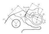
また、図6に示すように、第1カム係合面47aによりラッチ27が押圧される第1ラッチ係合面28aは、ラッチ27の板厚面に配置されている。つまり、ラッチ27の軸線O3及び第1ラッチ係合面(28a)を結ぶ直線LNが不変であるとすれば、ラッチ27の板厚面に配置される図6に示す第1ラッチ係合面28aであるときにラッチ27の軸線O3との離間距離Lが最大距離L3となる。従って、例えばラッチ27に対しカム部材45による押圧に抗して回動しようとするトルク(付勢部材50の発生するトルクを含む)が作用した場合、該トルクに基づき第1カム係合面47aに加わる荷重を最小にできる。これは、ラッチ27に作用したトルクTgに基づき第1カム係合面47aに加わる荷重Fgは、下式(2)により求められ、例えばトルクTgが一定であれば、離間距離Lが長いほど荷重Fgが小さくなるためである。
また、図6に示すように、第1カム係合面47aによりラッチ27が押圧される第1ラッチ係合面28aは、ラッチ27の板厚面に配置されている。つまり、ラッチ27の軸線O3及び第1ラッチ係合面(28a)を結ぶ直線LNが不変であるとすれば、ラッチ27の板厚面に配置される図6に示す第1ラッチ係合面28aであるときにラッチ27の軸線O3との離間距離Lが最大距離L3となる。従って、例えばラッチ27に対しカム部材45による押圧に抗して回動しようとするトルク(付勢部材50の発生するトルクを含む)が作用した場合、該トルクに基づき第1カム係合面47aに加わる荷重を最小にできる。これは、ラッチ27に作用したトルクTgに基づき第1カム係合面47aに加わる荷重Fgは、下式(2)により求められ、例えばトルクTgが一定であれば、離間距離Lが長いほど荷重Fgが小さくなるためである。
荷重Fg=トルクTg/離間距離L …(2)
既述のように、第1カム係合面47aは、軸受孔46(カム支持部31a)を中心とする図示時計回りの周方向に向かうに従い径方向外側に変位しており、第1カム係合面47aに圧力角が設定されている。この圧力角をθで表すと、第1カム係合面47aにはその接線方向に解除荷重Fg・sinθが作用する。従って、この解除荷重Fg・sinθが前記ばね荷重Fsと、第1カム係合面47a及び第1ラッチ係合面28aの間の摩擦力Ffとの合計荷重よりも大きくなると、カム部材45によるラッチ27の追込みが成立しなくなる可能性がある。
既述のように、第1カム係合面47aは、軸受孔46(カム支持部31a)を中心とする図示時計回りの周方向に向かうに従い径方向外側に変位しており、第1カム係合面47aに圧力角が設定されている。この圧力角をθで表すと、第1カム係合面47aにはその接線方向に解除荷重Fg・sinθが作用する。従って、この解除荷重Fg・sinθが前記ばね荷重Fsと、第1カム係合面47a及び第1ラッチ係合面28aの間の摩擦力Ffとの合計荷重よりも大きくなると、カム部材45によるラッチ27の追込みが成立しなくなる可能性がある。
しかしながら、荷重Fg(解除荷重)を相対的に小さくできることで、ラッチ27のがたつきを抑制でき、ひいてはストライカ20のがたつきをいっそう抑制できる。
以上詳述したように、本実施形態によれば、以下に示す効果が得られるようになる。
以上詳述したように、本実施形態によれば、以下に示す効果が得られるようになる。
(1)本実施形態では、トーションばね55に付勢されるカム部材45は、第1カム係合面47aでロック位置にあるラッチ27を押圧してストライカ20がベース溝部24a,25aの底面241a,251aに当接するようにラッチ27を回動させる。これにより、ラッチ27による拘束状態にあるストライカ20のがたつきが抑制される。この場合、ポール支持部31bの軸線O1及び第1カム係合面47aの離間距離L1よりも、カム支持部31aの軸線O2及び第1カム係合面47aの離間距離L2が短く設定されている。従って、例えば両離間距離L1,L2が互いに同等に設定されている場合に比べて、第1カム係合面47aに対しトーションばね55の付勢力をより高効率に伝達できる。そして、このときのトーションばね55の付勢力(ばね荷重Fs)に基づき第1カム係合面47a及び第1ラッチ係合面28aの間に生じる摩擦力が相対的に増加することで、ラッチ27のがたつきを抑えることができ、ひいてはストライカ20のがたつきをいっそう抑えることができる。あるいは、トーションばね55の付勢力をより高効率に伝達できる分、また、ポール支持部31b及びカム支持部31aは、ポールカム軸30が一体的に有することで、部品点数の増加を抑制できる。
(2)本実施形態では、第1カム係合面47aによりラッチ27が押圧される第1ラッチ係合面28aは、ラッチ27の板厚面に配置されている。従って、例えばラッチ27の軸線O3及び第1ラッチ係合面(28a)を結ぶ直線LNが不変であるとすれば、ラッチ27の板厚面に第1ラッチ係合面が配置されるときにラッチ27の軸線O3及び第1ラッチ係合面の離間距離Lが最大になる。従って、例えばラッチ27に対しカム部材45による押圧に抗して回動しようとするトルクTgが作用した場合、該トルクTgに基づき第1カム係合面47aに加わる荷重Fgを最小にできる。これにより、ラッチ27のがたつきを抑制でき、ひいてはストライカ20のがたつきをいっそう抑制できる。
(3)本実施形態では、ポール支持部31b及びカム支持部31aは、互いに異なる直径D1,D2に設定されており、ポール支持部31b及びカム支持部31aの偏心量Δは、ポール支持部31b及びカム支持部31aの直径差(=D2-D1)の範囲に設定されている。従って、相対的に直径D1の小さなポール支持部31bは、その径方向外側にカム支持部31aから突出しないことで、例えばこれに軸支されるポール40が軸線O1に対して傾く可能性を低減できる。これは、ポール40が軸線O1に対して傾こうとしても、軸受孔41の周縁部がカム支持部31aに当接することで規制されるためである。
(4)本実施形態では、第2ポール係合面42bに対する第2カム係合面47bの前述の突出分によって、カム部材45がカム許容位置からの回動を開始するタイミングは、ポール40が規制位置に到達するタイミングよりも遅延されている。従って、ポール40によりロック位置にあるラッチ27のアンロック位置への回動が規制された後で、カム部材45がカム許容位置から回動し始めることで、ポール40及びカム部材45の動作をより安定化できる。
(5)本実施形態では、規制突部43及びその係入される規制孔48により、ロック解除操作時、カム部材45がカム許容位置に到達するタイミングは、ポール40が許容位置に到達するタイミングと一致するように設定されている。従って、ポール40及びカム部材45によりラッチ27の回動が同時に許容されることで、該ラッチ27をアンロック位置に向かって円滑に回動させることができる。
(6)本実施形態では、ポール40及びカム部材45の連係に係る規制突部43及び規制孔48は、ポール40及びカム部材45にそれぞれ一体的に設けられていることで、部品点数の増大を抑制することができる。従って、部品点数の増大に伴う組付誤差の増大を回避することができ、ひいては組付工数を削減することができる。
(7)本実施形態では、カム部材45によるラッチ27の追込み時には、規制位置にあるポール40の第1ポール係合面42aから第1ラッチ係合面28aが挿通孔27aを中心とする周方向に離れる。従って、ラッチ27との干渉によってポール40が規制位置から揺動することを抑制できる。そして、ラッチ27の追込み状態において、規制位置でのポール40の待機をより安定的に行うことができる。
(8)本実施形態では、カム部材45の規制孔48が閉じていることで、即ち開いた溝状でないことで、例えば第1カム係合面47aで第1ラッチ係合面28aを押圧する際に突片47が変形することを抑制できる。
なお、上記実施形態は以下のように変更してもよい。
・前記実施形態において、カム部材45がカム許容位置からの回動を開始するタイミングは、ポール40が規制位置に到達するタイミングよりも遅延されていなくてもよい。例えばカム部材45がカム許容位置からの回動を開始するタイミングは、ポール40が規制位置に到達するタイミングと一致してもよいし、ポール40が許容位置からの回動を開始するタイミングと一致してもよい。
・前記実施形態において、カム部材45がカム許容位置からの回動を開始するタイミングは、ポール40が規制位置に到達するタイミングよりも遅延されていなくてもよい。例えばカム部材45がカム許容位置からの回動を開始するタイミングは、ポール40が規制位置に到達するタイミングと一致してもよいし、ポール40が許容位置からの回動を開始するタイミングと一致してもよい。
・前記実施形態において、ポール支持部31b及びカム支持部31aの偏心量(Δ)は、ポール支持部31b及びカム支持部31aの直径差(=D2-D1)の範囲を超えていてもよい。この場合、ポール支持部31b及びカム支持部31aの直径D1,D2は、互いに同等であってもよい。
・前記実施形態において、第1カム係合面47aによりラッチ27が押圧される第1ラッチ係合面(28a)は、ラッチ27の板厚面以外に配置されてもよい。例えばラッチ27(主面)にその軸線方向と平行に突部を突設するとともに、該突部に第1カム係合面47aの押圧可能な第1ラッチ係合面(28a)を形成してもよい。
・前記実施形態において、ポール40及びカム部材45と、規制突部43及び規制孔48の配置関係は互いに逆であってもよい。すなわち、ポール40に規制孔(48)を形成するとともに、カム部材45に規制突部(43)を突設してもよい。
・前記実施形態において、車体(固定部材)及びシートバック12(可動部材)と、ストライカ20及びロック装置21との配置関係は互いに逆であってもよい。すなわち、車体(固定部材)にロック装置21を配置するとともに、シートバック12(可動部材)にストライカ20を配置してもよい。
・本発明は、シートクッション11の前後位置を調整する装置(スライド装置)、上下位置を調整する装置(リフト装置)、シートクッション11の長さ調整装置、及びオットマン装置に適用してもよい。あるいは、本発明は、車両に搭載される可動部材の位置を調整する適宜の装置に適用してもよい。具体的には、ステアリングのチルト調整装置、及びドアロック装置に適用してもよい。
Claims (5)
- 固定部材及び可動部材の一方に固定されるように構成されたストライカの挿入可能なベース溝部を有して前記固定部材及び前記可動部材の他方に固定されるベース部材と、
第1軸部及び該第1軸部に対して偏心した第2軸部を一体的に有して前記ベース部材に回動不能に固定された支持軸と、
前記ベース部材に回動自在に連結され、前記ベース溝部との間で前記ストライカを拘束するロック位置と前記ストライカを解放するアンロック位置との間で回動可能なラッチと、
前記第1軸部に軸支され、前記ロック位置及び前記アンロック位置の間での前記ラッチの回動を許容する許容位置と前記ロック位置にある前記ラッチの前記アンロック位置への回動を規制する規制位置との間で回動可能なポールと、
前記第2軸部に軸支され、前記ロック位置にある前記ラッチを押圧面で押圧して前記ストライカが前記ベース溝部の底面に当接するように前記ラッチを回動させるカム部材と、
前記支持軸に巻回され、前記カム部材が前記押圧面で前記ラッチを押圧する回動方向に向かって前記カム部材を付勢するトーションばねとを備え、
前記第2軸部の軸線及び前記押圧面の離間距離は、前記第1軸部の軸線及び前記押圧面の離間距離よりも短く設定された、車両用ロック装置。 - 請求項1に記載の車両用ロック装置において、
前記押圧面により前記ラッチが押圧される被押圧面は、前記ラッチの板厚面に配置された、車両用ロック装置。 - 請求項1又は2に記載の車両用ロック装置において、
前記第1軸部及び前記第2軸部は、互いに異なる直径に設定されており、
前記第1軸部及び前記第2軸部の偏心量は、前記第1軸部及び前記第2軸部の直径差の範囲に設定された、車両用ロック装置。 - 請求項1~3の何れか一項に記載の車両用ロック装置において、
前記カム部材は、前記ロック位置及び前記アンロック位置の間での前記ラッチの回動を許容するカム許容位置からの回動に伴い、前記ロック位置にある前記ラッチを前記押圧面で押圧するように構成されており、
前記カム部材が前記カム許容位置からの回動を開始するタイミングは、前記ポールが前記規制位置に到達するタイミングよりも遅延された、車両用ロック装置。 - 請求項4に記載の車両用ロック装置において、
前記ポールは、ロック解除操作に伴い前記規制位置から前記許容位置へと回動するように構成されており、
前記カム部材は、前記ポールが前記許容位置に向かって回動することで前記トーションばねの付勢力に抗して前記カム許容位置に向かって回動するように前記ポールに連係されており、
前記カム部材が前記カム許容位置に到達するタイミングは、前記ポールが前記許容位置に到達するタイミングと一致するように設定された、車両用ロック装置。
Applications Claiming Priority (2)
| Application Number | Priority Date | Filing Date | Title |
|---|---|---|---|
| JP2015246560A JP2017110435A (ja) | 2015-12-17 | 2015-12-17 | 車両用ロック装置 |
| JP2015-246560 | 2015-12-17 |
Publications (1)
| Publication Number | Publication Date |
|---|---|
| WO2017104628A1 true WO2017104628A1 (ja) | 2017-06-22 |
Family
ID=59056620
Family Applications (1)
| Application Number | Title | Priority Date | Filing Date |
|---|---|---|---|
| PCT/JP2016/086961 Ceased WO2017104628A1 (ja) | 2015-12-17 | 2016-12-13 | 車両用ロック装置 |
Country Status (2)
| Country | Link |
|---|---|
| JP (1) | JP2017110435A (ja) |
| WO (1) | WO2017104628A1 (ja) |
Cited By (3)
| Publication number | Priority date | Publication date | Assignee | Title |
|---|---|---|---|---|
| WO2019209936A1 (en) | 2018-04-25 | 2019-10-31 | Clearink Displays, Inc. | Apparatus and method for reflective image display with dielectric layer |
| CN110901482A (zh) * | 2019-12-31 | 2020-03-24 | 无锡全盛安仁机械有限公司 | 一种轻量化的汽车座椅靠背锁 |
| CN112144989A (zh) * | 2020-04-02 | 2020-12-29 | 深圳市海月云科技有限公司 | 一种新型摩托车锁 |
Families Citing this family (2)
| Publication number | Priority date | Publication date | Assignee | Title |
|---|---|---|---|---|
| CN112193132A (zh) * | 2020-09-23 | 2021-01-08 | 飞适动力汽车座椅零件(上海)有限公司 | 一种座椅靠背锁用无限夹紧锁环 |
| KR102798355B1 (ko) * | 2023-12-21 | 2025-04-23 | 대일공업주식회사 | 차량 시트의 전자식 잠금장치 |
Citations (3)
| Publication number | Priority date | Publication date | Assignee | Title |
|---|---|---|---|---|
| JPS55166552U (ja) * | 1979-05-17 | 1980-11-29 | ||
| JP2005138785A (ja) * | 2003-11-10 | 2005-06-02 | Fuji Kiko Co Ltd | シートロック装置 |
| WO2006095517A1 (ja) * | 2005-03-04 | 2006-09-14 | Toyota Boshoku Kabushiki Kaisha | ロック装置 |
-
2015
- 2015-12-17 JP JP2015246560A patent/JP2017110435A/ja active Pending
-
2016
- 2016-12-13 WO PCT/JP2016/086961 patent/WO2017104628A1/ja not_active Ceased
Patent Citations (3)
| Publication number | Priority date | Publication date | Assignee | Title |
|---|---|---|---|---|
| JPS55166552U (ja) * | 1979-05-17 | 1980-11-29 | ||
| JP2005138785A (ja) * | 2003-11-10 | 2005-06-02 | Fuji Kiko Co Ltd | シートロック装置 |
| WO2006095517A1 (ja) * | 2005-03-04 | 2006-09-14 | Toyota Boshoku Kabushiki Kaisha | ロック装置 |
Cited By (3)
| Publication number | Priority date | Publication date | Assignee | Title |
|---|---|---|---|---|
| WO2019209936A1 (en) | 2018-04-25 | 2019-10-31 | Clearink Displays, Inc. | Apparatus and method for reflective image display with dielectric layer |
| CN110901482A (zh) * | 2019-12-31 | 2020-03-24 | 无锡全盛安仁机械有限公司 | 一种轻量化的汽车座椅靠背锁 |
| CN112144989A (zh) * | 2020-04-02 | 2020-12-29 | 深圳市海月云科技有限公司 | 一种新型摩托车锁 |
Also Published As
| Publication number | Publication date |
|---|---|
| JP2017110435A (ja) | 2017-06-22 |
Similar Documents
| Publication | Publication Date | Title |
|---|---|---|
| EP2682302B1 (en) | Vehicle lock | |
| US6023994A (en) | Double-sided reclining apparatus | |
| US9376036B2 (en) | Disc recliner with internal leaf springs | |
| US5873630A (en) | Rotary-cam type reclining device | |
| JP4853501B2 (ja) | 車両用シートリクライニング装置 | |
| US9630529B2 (en) | Seat reclining apparatus | |
| JP4955368B2 (ja) | 車両座席用取り付け具 | |
| JP5674998B2 (ja) | 車両シート用継手システム | |
| US10112507B2 (en) | Seat reclining apparatus | |
| KR101793440B1 (ko) | 차량용 시트의 리클라이너 | |
| JP2017110435A (ja) | 車両用ロック装置 | |
| JP5434968B2 (ja) | 車両用シートリクライニング装置 | |
| US9371015B2 (en) | Vehicle seat | |
| EP1908373B1 (en) | Lock device and seat reclining device | |
| JP2016027968A (ja) | 車両用シートロック装置 | |
| JP2007136172A5 (ja) | ||
| CN102438857A (zh) | 具有嵌入环的止动配件 | |
| US20110084532A1 (en) | Disc Recliner With Integral Travel Stops | |
| CN103534137A (zh) | 双凸轮倾角调节器 | |
| WO2018092570A1 (ja) | 車両用ロック装置 | |
| JP5050733B2 (ja) | ロック装置 | |
| JP4973297B2 (ja) | ロック装置 | |
| US9221363B2 (en) | Seat reclining apparatus | |
| JP2010274770A (ja) | ロック装置 | |
| JP5970720B2 (ja) | ロック装置 |
Legal Events
| Date | Code | Title | Description |
|---|---|---|---|
| 121 | Ep: the epo has been informed by wipo that ep was designated in this application |
Ref document number: 16875605 Country of ref document: EP Kind code of ref document: A1 |
|
| NENP | Non-entry into the national phase |
Ref country code: DE |
|
| 122 | Ep: pct application non-entry in european phase |
Ref document number: 16875605 Country of ref document: EP Kind code of ref document: A1 |