EP1908373B1 - Lock device and seat reclining device - Google Patents
Lock device and seat reclining device Download PDFInfo
- Publication number
- EP1908373B1 EP1908373B1 EP06781642A EP06781642A EP1908373B1 EP 1908373 B1 EP1908373 B1 EP 1908373B1 EP 06781642 A EP06781642 A EP 06781642A EP 06781642 A EP06781642 A EP 06781642A EP 1908373 B1 EP1908373 B1 EP 1908373B1
- Authority
- EP
- European Patent Office
- Prior art keywords
- cam
- lock
- face
- guide
- guided
- Prior art date
- Legal status (The legal status is an assumption and is not a legal conclusion. Google has not performed a legal analysis and makes no representation as to the accuracy of the status listed.)
- Ceased
Links
- 230000002093 peripheral effect Effects 0.000 claims description 24
- 230000001629 suppression Effects 0.000 abstract 2
- 230000001105 regulatory effect Effects 0.000 description 7
- 238000007796 conventional method Methods 0.000 description 2
- 238000000034 method Methods 0.000 description 2
- 238000003466 welding Methods 0.000 description 2
- 238000011161 development Methods 0.000 description 1
- 230000018109 developmental process Effects 0.000 description 1
- 230000000694 effects Effects 0.000 description 1
- 230000001360 synchronised effect Effects 0.000 description 1
Images


Classifications
-
- B—PERFORMING OPERATIONS; TRANSPORTING
- B60—VEHICLES IN GENERAL
- B60N—SEATS SPECIALLY ADAPTED FOR VEHICLES; VEHICLE PASSENGER ACCOMMODATION NOT OTHERWISE PROVIDED FOR
- B60N2/00—Seats specially adapted for vehicles; Arrangement or mounting of seats in vehicles
- B60N2/02—Seats specially adapted for vehicles; Arrangement or mounting of seats in vehicles the seat or part thereof being movable, e.g. adjustable
- B60N2/22—Seats specially adapted for vehicles; Arrangement or mounting of seats in vehicles the seat or part thereof being movable, e.g. adjustable the back-rest being adjustable
- B60N2/235—Seats specially adapted for vehicles; Arrangement or mounting of seats in vehicles the seat or part thereof being movable, e.g. adjustable the back-rest being adjustable by gear-pawl type mechanisms
- B60N2/2356—Seats specially adapted for vehicles; Arrangement or mounting of seats in vehicles the seat or part thereof being movable, e.g. adjustable the back-rest being adjustable by gear-pawl type mechanisms with internal pawls
- B60N2/236—Seats specially adapted for vehicles; Arrangement or mounting of seats in vehicles the seat or part thereof being movable, e.g. adjustable the back-rest being adjustable by gear-pawl type mechanisms with internal pawls linearly movable
Definitions
- the present invention relates to a lock device capable of causing engagement and release between two members, and a seat reclining apparatus using this lock device for adjusting the angle between a seat cushion and a seat back.
- Patent Document JP 2002-101996 has disclosed a technique below.
- This lock device is configured substantially as in unclaimed embodiments of the present invention described later. More specifically, as shown in FIGS. 7 and 8 , a lower guide 51, an upper gear 52, a ring holder 53, three poles 54, a cam 55, and a spring 56 are provided. Internal teeth 52a are formed on an inner circumferential face of the upper gear 52. On the other hand, external teeth 54a that become engaged with the internal teeth 52a are formed on the outer peripheral end faces of the three poles 54.
- the cam 55 swings between a lock phase and a release phase, thereby causing the three poles 54 to become synchronously engaged with or released from the internal teeth 52a.
- the spring 56 biases the cam 55 in a direction to cause the poles 54 to become engaged with the internal teeth 52a.
- the lower guide 51 has guide portions 57 for guiding the cam 55 and the poles 54.
- the lower guide 51 and the upper gear 52 are opposed to each other and combined in a relatively rotatable manner.
- radial movement of the cam 55 is regulated by a guide face 57a that is constituted by the inner peripheral face of the guide portion 57 formed on the lower guide 51, and the cam 55 is guided so as to be swingable only in the peripheral direction.
- a guide face 57a that is constituted by the inner peripheral face of the guide portion 57 formed on the lower guide 51, and the cam 55 is guided so as to be swingable only in the peripheral direction.
- the cam 55 can loosely move to some extent in the radial direction.
- the clearance between the guide face 57a and the guided face 55a of the cam 55 is wide in a state where the cam 55 is close to the lock phase, and narrow in a state where the cam 55 is close to the release phase.
- the cam 55 in a state where the cam 55 is close to the lock phase and the poles 54 are not engaged with the internal teeth 52a of the upper gear 52, the cam 55 can move in the radial direction within the clearance between the guide face 57a and the guided face 55a.
- the cam 55 is decentered to any direction by a biasing force of the spring 56.
- the cam 55 when the cam 55 is locked by being displaced from the release phase to the lock phase, the three poles 54 are not synchronized with each other, and thus unevenness may occur in the timing to become engaged with the internal teeth 52a of the upper gear 52.
- the present invention was arrived at in view of the above-described problems, and it is an object thereof to provide: a lock device capable of suppressing a lack of smoothness in an unlocking operation, and of suppressing, in a case where there are a plurality of lock members that are operated by a cam member, unevenness in the timing for the plurality of lock members to become engaged in a locking operation; and a seat reclining apparatus using this lock device.
- the lock device comprises: a first member having an engaged portion; a lock member capable of being engaged with the engaged portion; a cam member swinging between a predetermined lock phase and release phase, thereby causing the lock member to operate between an engage posture and a release posture with respect to the engaged portion; a second member having a guiding portion for guiding swing of the cam member; and a biasing member for biasing the cam member in a peripheral direction, wherein the guiding portion has a plurality of guide faces that are arranged away from each other along a circumferential direction, the cam member has a plurality of guided faces that respectively abut against the plurality of guide faces in the release phase, and the guided face in a direction in which the cam member is decentered by a biasing force of the biasing member is extended to the release phase side with respect to the other guided faces.
- the cam member has a plurality of cam projecting portions that are formed so as to project outward in a radial direction, and a plurality of guided faces that are formed on outer peripheral portions of the respective cam projecting portions and that respectively abut against the plurality of guide faces in the release phase, the cam projecting portion in a direction in which the cam member is decentered by a biasing force of the biasing member has an extended portion expanded to the release phase side so as to be progressively away from an operation direction of the lock member as it extends toward an outer side in a radial direction in a state where the cam member is in the lock phase, and the guided face includes an outer peripheral portion of the extended portion.
- the guided face in a direction in which the cam member is decentered by a biasing force of the biasing member, and the guide face opposed thereto have an area in which the guided face and the guide face are opposed to each other in a state where the cam member is in the lock phase, and the length in a peripheral direction of the opposed area is at least one tenth of the distance from a swing axis of the cam member to the guided face.
- the length in the peripheral direction of the opposed area is preferably at least one eighth of the distance from the swing axis of the cam member to the guided face, and more preferably at least one fifth of this distance.
- the length in the peripheral direction of the area in which the guided face and the guide face are opposed to each other in a state where the cam member is in the lock phase is at least one tenth of the distance from the swing axis of the cam member to the guided face.
- the angle between a tangent of the guide face and a tangent of the guided face in the opposed area is not greater than 5° in a state where the cam member is in the lock phase. It is more preferable that the angle between a tangent of the guide face and a tangent of the guided face in the opposed area is not greater than 3°.
- the engaged portion is provided along a circumferential direction
- the cam member causes the lock members arranged in plural opposed to the engaged portion along a circumferential direction to synchronously operate, and the guide faces and the guided faces are not brought into contact with each other in a state where the cam member is in the lock phase and all of the lock members are engaged with the engaged portion.
- the cam member when the cam member is shifted to the lock phase and the lock members become engaged with the engaged portion, even if the cam member is decentered from the designed swing axis, for example, due to processing errors in size of the cam member, the lock members, and the first member, radial movement of the cam member is not regulated by the guide face of the guiding portion.
- the load can be applied equally to the plurality of lock members.
- the guide faces and the guided faces are formed such that a clearance between the guide faces and the guided faces becomes smaller as the cam member is displaced from the lock phase to the release phase side.
- the cam member can be guided as appropriate in the rotational direction, while the cam member in the lock phase is allowed to move to some extent in the radial direction, and a lack of smoothness is suppressed between the guided face and the guide face when the cam member is displaced from the lock phase to the release phase side.
- a seat reclining apparatus comprises the lock device having the above-described characteristics and can adjust the angle between a seat cushion and a seat back, wherein the first member is attached to either one of the seat cushion and the seat back, the second member is attached to the other of the seat cushion and the seat back, the first member and the second member are engaged with each other in a relatively rotatable manner, and the seat reclining apparatus further comprises an operation portion for swinging the cam member.
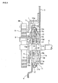
- FIG. 1 is a perspective view illustrating the mainframe of the seat reclining apparatus 2 according to this embodiment.
- the seat reclining apparatus 2 has a seat back frame 3 constituting the mainframe of a seat back, a seat cushion frame 4 constituting the mainframe of a seat cushion, the lock device 1 provided at a portion connecting the seat back frame 3 and the seat cushion frame 4, and an operating lever 5 and a lever shaft 6 serving as an operation portion for operating the lock device 1.
- the lock device 1 When the lock device 1 is in a lock state, the angle of the seat back frame 3 with respect to the seat cushion frame 4 is fixed.
- the lock device 1 is shifted to an unlock state by operation of the operating lever 5, the angle of the seat back frame 3 with respect to the seat cushion frame 4 can be changed.
- an outer catch member 7 is attached to the seat back frame 3, and an inner catch member 8 is attached to the seat cushion frame 4.
- An inner end portion 9a of a seat back biasing spring 9 constituted by a spiral spring is caught by the inner catch member 8, and an outer end portion 9b of the seat back biasing spring 9 is caught by the outer catch member 7. Accordingly, the seat back biasing spring 9 biases the seat back frame 3 to the front side of the seat (left side in FIG. 1 ).
- a similar configuration excluding the operating lever 5 is provided on the opposite side in the width direction of the seat.
- the lever shaft 6 is coupled with a counterpart shaft provided on the opposite side in the width direction of the seat.
- the lock devices 1 respectively provided on both sides in the width direction of the seat are moved in conjunction with each other by operation of the operating lever 5.
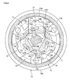
- FIG. 2 is an exploded perspective view of the lock device 1.
- FIG. 3 is a cross-sectional view of the lock device 1.
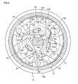
- FIG. 4 is a view illustrating a state of a cam 13 and poles 12 when the cam 13 of the lock device 1 is in a lock phase.
- FIG. 5 is a view illustrating a state of the cam 13 and the poles 12 when the cam 13 of the lock device 1 is in a release phase.
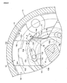
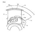
- FIG. 6 is an enlarged view of the main portions of FIG. 4 . As shown in FIGS.
- the lock device 1 is provided with: an upper gear 11 whose inner circumferential face has internal teeth 11a; three poles 12 whose outer peripheral end faces have external teeth 12a that can become engaged with the internal teeth 11a; the cam 13 swinging between a predetermined lock phase and release phase, thereby causing the poles 12 to operate between an engage posture and a release posture with respect to the internal teeth 11a of the upper gear 11; a lower guide 15 having guide portions 14 for guiding swing of the cam 13; and a lock spring 16 for biasing the cam 13 in the peripheral direction. Furthermore, the upper gear 11 and the lower guide 15 are engaged with each other in a relatively rotatable manner. A ring holder 17 fits to the outside of outer circumferential portions of both the upper gear 11 and the lower guide 15, and thus the upper gear 11 and the lower guide 15 are caught so as not to be separated from each other.
- the upper gear 11 corresponds to a "first member” in the present invention
- the internal teeth 11a thereof correspond to an "engaged portion” in the present invention
- the lower guide 15 corresponds to a “second member” in the present invention
- the guide portions 14 thereof correspond to "guiding portions” in the present invention.
- the poles 12 correspond to “lock members” in the present invention
- the cam 13 corresponds to a “cam member” in the present invention
- the lock spring 16 corresponds to a "biasing member” in the present invention.
- the upper gear 11 is substantially disk-shaped.
- a first recess portion 11c (see FIG. 3 ) in the shape of a recess that has a cylindrical inner circumferential face coaxial with an outer circumferential face 11b is formed in the upper gear 11 on the side of the lower guide 15.
- the internal teeth 11a are formed on the cylindrical inner circumferential face of the first recess portion 11c.
- a second recess portion 11d in the shape of a recess that has a cylindrical inner circumferential face coaxial with the outer circumferential face 11b and that is deeper than the bottom face of the first recess portion 11c is formed in the first recess portion 11c on the inner side in the radial direction.
- the face of the upper gear 11 on the side opposite to the lower guide 15 has a plurality of (herein, six) engagement projecting portions 11e that are provided at constant intervals in the circumferential direction.
- a plurality of (herein, six) engagement holes 3a are provided in the seat back frame 3 at positions corresponding to the engagement projecting portions 11e.
- the upper gear 11 is integrally fixed to the seat back frame 3 by welding or the like with the engagement projecting portions 11e engaged with the engagement holes 3a.
- the portion of the upper gear 11 on the side of the lower guide 15 fits into the third recess portion 15a of the lower guide 15 described later.
- the outer circumferential face 11b of the upper gear 11 fits to an inner circumferential face 15c of the third recess portion 15a in a slidable manner. Accordingly, the upper gear 11 and the lower guide 15 are engaged with each other in a relatively rotatable manner.
- the shape of the upper gear 11 described above is formed by half blanking (incomplete blanking) or the like.
- the lower guide 15 is substantially disk-shaped.
- the third recess portion 15a in the shape of a recess that has the cylindrical inner circumferential face 15c coaxial with an outer circumferential face 15e is formed in the lower guide 15 on the side of the upper gear 11.
- the outer circumferential face 11b of the upper gear 11 fits to the inner circumferential face 15c of the third recess portion 15a. Accordingly, the upper gear 11 fits into and becomes engaged with the third recess portion 15a.
- the plurality of (herein, six) guide portions 14 formed so as to project with respect to a bottom face 15d of the third recess portion 15a are arranged away from each other in the circumferential direction.
- the guide portions 14 have cam guide faces 14a that are formed in the circumferential direction and that are for guiding swing of the cam 13.
- the plurality of (herein, six) cam guide faces 14a are arranged away from each other in the circumferential direction.
- the guide portions 14 also have pole guide faces 14b that are formed substantially in the radial direction such that the pole guide faces 14b of the adjacent guide portions 14 are arranged parallel to each other, and that are for guiding radial movement of the poles 12.
- the cam guide faces 14a correspond to "guide faces" in the present invention.
- the fourth recess portion 15b in the shape of a recess that has a cylindrical inner circumferential face coaxial with the outer circumferential face 15e and that is deeper than the bottom face 15d of the third recess portion 15a is formed in the third recess portion 15a on the inner side in the radial direction.
- the lock spring 16 is disposed in the fourth recess portion 15b on the inner side in the radial direction.
- a cutout 15f extending outward in the radial direction is formed on a part of an inner circumferential face of the fourth recess portion 15b.
- An outer end portion 16a of the lock spring 16 constituted by a spiral spring is caught by the cutout 15f.
- a through hole 15g through which the lever shaft 6 passes is provided in the lower guide 15 at the central portion in the radial direction.
- the face of the lower guide 15 on the side opposite to the upper gear 11 has a plurality of engagement projecting portions 15h that are provided at constant intervals in the circumferential direction.
- a plurality of engagement holes 4a are provided in the seat cushion frame 4 at positions corresponding to the engagement projecting portions 15h.
- the lower guide 15 is integrally fixed to with the seat cushion frame 4 by welding or the like with the engagement projecting portions 15h engaged with the engagement holes 4a.
- the shape of the lower guide 15 described above is formed by half blanking (incomplete blanking) or the like.
- the ring holder 17 is ring-shaped.
- the ring holder 17 is provided so as to fit to the outside of outer circumferential portions of both the upper gear 11 and the lower guide 15, in a state where the outer circumferential face 11b of the upper gear 11 fits to the inner circumferential face 15c of the third recess portion 15a of the lower guide 15 and thus the upper gear 11 and the lower guide 15 become engaged with each other. Accordingly, the upper gear 11 and the lower guide 15 are allowed to rotate relative to each other, and caught so as not to be separated from each other in the axial direction.
- the cam 13 is in the shape of a irregular-shaped plate in which a plurality of (herein, three) cam projecting portions 13a that are formed so as to project outward in the radial direction from the central portion in the radial direction provided with a boss portion 13e described later are arranged away from each other in the circumferential direction. Faces on a guide circumference C (see FIG. 6 ) constituted by a locus of rotation of the outermost peripheral portions of the cam projecting portions 13a constitute guided faces 13b that are guided by the cam guide faces 14a of the guide portions 14. Thus, as shown in FIGS. 4 and 5 , the plurality of (herein, three) guided faces 13b are arranged away from each other along the guide circumference C.
- Protruding portions 13d projecting parallel to a swing axis X of the cam 13 are formed on faces of the cam projecting portions 13a on the side of the upper gear 11. The protruding portions 13d are inserted into engagement elongated holes 12c formed through the poles 12 as described later.
- the cylindrical boss portion 13e coaxial with the swing axis X is formed so as to project from the face of the cam 13 on the side of the lower guide 15.
- a fit hole 13f is provided along the swing axis X, at the central portion of the cam 13 in the radial direction including the boss portion 13e.
- the lever shaft 6 is inserted into and fits to the inside of the fit hole 13f. Accordingly, the cam 13 rotates integrally with the lever shaft 6 and the operating lever 5. More specifically, the operating lever 5 functions as an operation portion for swinging the cam 13.
- a cutout 13g (see FIGS. 4 to 6 ) extending inward in the radial direction is formed on a part of an outer circumferential face of the boss portion 13e.
- An inner end portion 16b of the lock spring 16 constituted by a spiral spring is caught by the cutout 13g.
- the lock spring 16 has the outer end portion 16a that is caught by the cutout 15f of the lower guide 15 and the inner end portion 16b that is caught by the cutout 13g of the cam 13.
- the lock spring 16 is a spiral spring wound counterclockwise from the inner circumferential side to the outer circumferential side when viewed from the upper gear 11.
- the lock spring 16 biases the cam 13 in a direction to rotate the cam 13 counterclockwise (counterclockwise in FIGS. 4 to 6 ) when viewed from the upper gear 11. More specifically, the lock spring 16 biases the cam 13 in a rotational direction to the lock phase side.
- the poles 12 are biased by the lock spring 16 in a direction to cause the poles 12 to keep the engage posture with the internal teeth 11a of the upper gear 11.
- the lock spring 16 biases the cam 13 in a substantially peripheral direction.
- the biasing force is not in the peripheral direction in the strict sense, and also causes a biasing force to act in a direction to decenter the cam 13.
- the lock spring 16 causes a biasing force to act on the cutout 13g of the cam 13 catching the inner end portion 16b, in a direction of the tangent of a circumferential portion in the vicinity of the inner end portion 16b (substantially upward in FIGS. 4 and 6 ).
- the cam 13 receives a biasing force of the lock spring 16 such that the cam 13 is decentered substantially upwardly in FIGS. 4 and 6 .
- the pole 12 is substantially in the shape of a rectangular plate.
- the plurality of (herein, three) poles 12 are radially arranged away from each other in the circumferential direction.
- Each of the poles 12 is guided in a movable manner in the radial direction, with both side faces 12b in the shape of parallel flat faces sliding along the pole guide faces 14b of the guide portions 14 provided on the lower guide 15.
- the external teeth 12a that become engaged with the internal teeth 11a of the upper gear 11 are formed on the outer peripheral end face of the pole 12.
- the external teeth 12a are opposed to the internal teeth 11a.
- the engagement elongated hole 12c passing through in the thickness direction is formed in the vicinity of an inner peripheral side portion of the pole 12.
- the engagement elongated hole 12c is formed such that its length direction is inclined with respect to the circumference Centered around the swing axis X of the cam 13.
- the engagement elongated hole 12c is inclined inward in the radial direction toward the lock phase side in the rotational direction of the cam 13 (counterclockwise in FIGS. 4 to 6 ).
- the protruding portion 13d of the cam 13 is inserted into the engagement elongated hole 12c. Accordingly, the poles 12 and the cam 13 become engaged so as to move in conjunction with each other.
- a stepped portion is formed on the face of the pole 12 on the side of the lower guide 15, at a middle portion in the length direction between the external teeth 12a and the engagement elongated hole 12c.
- the inner peripheral face of the stepped portion constitutes the contact face 12d that abuts against the cam face 13c of the cam 13.
- the contact face 12d has a rough face corresponding to the cam face 13c when viewed from above (as shown in FIGS. 4 to 6 ).
- the protruding portion 13d of the cam 13 relatively moves counterclockwise within the engagement elongated hole 12c, and presses a side face of the engagement elongated hole 12c outward in the radial direction. Furthermore, the cam face 13c of the cam 13 presses the contact face 12d of the pole 12 outward in the radial direction. Accordingly, the pole 12 moves along the pole guide face 14b of the guide portions 14 outward in the radial direction, and obtains an engage posture in which the external teeth 12a become engaged with the internal teeth 11a of the upper gear 11 as shown in FIG. 4 .
- the cam 13 swings between the lock phase and the release phase, and thus the pole 12 operates between an engage posture to become engaged with the internal teeth 11a of the upper gear 11 and a release posture to release the engagement.
- the pole 12 is in the release posture, the upper gear 11 and the lower guide 15 are allowed to rotate relative to each other.
- the pole 12 is in the engage posture, the upper gear 11 and the lower guide 15 are prevented from rotating relative to each other.
- the plurality of (herein, three) guided faces 13b (including an extended guided face 13b described later) of the cam 13 and the cam guide faces 14a of the guide portions 14 opposed thereto are not brought into contact with each other in a state where the cam 13 is in the lock phase and all of the external teeth 12a of the poles 12 are engaged with the internal teeth 11a of the upper gear 11 as shown in FIGS. 4 and 6 . More specifically, the cam 13 is supported in the radial direction not by the guide portions 14 but by the poles 12 in the lock phase. With this configuration, in the lock phase, radial movement of the cam 13 is not regulated by the guide portions 14, and the cam 13 is allowed to be decentered.
- This configuration can be achieved by designing a gap N at a position where the guided face 13b and the cam guide face 14a are closest to each other when the cam 13 is in the lock phase, to be equal to or larger than the amount in which the swing axis X of the cam 13 is decentered by processing errors in size of the cam 13, the poles 12, and the upper gear 11.
- the guided faces 13b and the cam guide faces 14a abut against each other in a state where the cam 13 is in the release phase as shown in FIG. 5 . More specifically, the guided faces 13b of the cam 13 and the cam guide faces 14a of the guide portions 14 are formed such that a clearance between the mutually opposed faces becomes smaller as the cam 13 is displaced from the lock phase to the release phase side.
- the guided face 13b of the cam 13 is formed so as to be on the guide circumference C.
- the cam guide face 14a of the guide portion 14 is formed so as to have a face gradually closer to the guide circumference C from the lock phase side in the rotational direction of the cam 13 (hereinafter, simply referred to as the "lock phase side”) to the release phase side in the rotational direction of the cam 13 (hereinafter, simply referred to as the "release phase side”), and matches the guide circumference C in the vicinity of its end portion on the release phase side.
- an area that matches the guide circumference C serves as a regulation area substantially for regulating decentering of the swing axis X of the cam 13 and for guiding swing, and an area withdrawn outward in the radial direction from the guide circumference C serves as an introduction area for smoothly introducing the guided face 13b of the cam 13 to the regulation area.
- the cam projecting portion 13a in a direction in which the cam 13 is decentered (substantially above in FIGS. 4 to 6 ) by a biasing force of the lock spring 16 has an extended portion (expanded portion) E expanded to the release phase side so as to be away from the operation direction of the pole 12 (herein, the direction parallel to the pole guide face 14b) toward the outer side in the radial direction in a state where the cam 13 is in the lock phase as shown in FIG. 6 .
- the extended portion E has a flat side face Ea that is formed so as to have a predetermined angle with respect to the operation direction of the pole 12, and to be away to the release phase side toward the outer side in the radial direction, in a state where the cam 13 is in the lock phase.
- the shape of the side face Ea of the extended portion E is not limited to a flat face, and the side face Ea also may be a curved face that is formed so as to be away to the release phase side toward the outer side in the radial direction.
- the guided face 13b of the cam projecting portion 13a having the extended portion E includes the outer peripheral portion of the extended portion E.
- the entire outer peripheral face of the extended portion E serves as the guided face 13b on the guide circumference C.
- the guided face 13b in a direction in which the cam 13 is decentered by a biasing force of the lock spring 16 is extended to the release phase side with respect to the other guided faces 13b.
- the guided face 13b of the cam projecting portion 13a provided with the extended portion E, and the cam guide face 14a of the guide portion 14 opposed thereto have an opposed area A in which the guided face 13b and the cam guide face 14a are opposed to each other, in a state where the cam 13 is in the lock phase.
- the length of the arc of the opposed area A in a direction along the guide circumference C is one tenth or more of a distance D (herein, the radius of the guide circumference C) from the swing axis X of the cam 13 to the guided face 13b, preferably one eighth or more of the distance D, and more preferably one fifth or more of the distance D.
- a distance D herein, the radius of the guide circumference C
- the upper limit of the length of the arc of the opposed area A in the direction along the guide circumference C except for a limitation due to the shape and the arrangement of the cam projecting portion 13a and the guide portion 14, and any length may be applied.
- the effect of suppressing decentering of the cam 13 practically does not change even if the length of the arc of the opposed area A in the direction along the guide circumference C is more than a certain length.
- Such an upper limit of the length of the arc of the opposed area A in the direction along the guide circumference C varies depending on the shape of the cam projecting portion 13a, the guided face 13b thereof, the guide portion 14, and the cam guide face 14a thereof, but the upper limit is approximately half to one third of the distance D from the swing axis X of the cam 13 to the guided face 13b, for example.
- the opposed area A of the guided face 13b of the cam 13 and the cam guide face 14a of the guide portion 14 is provided, and thus decentering of the cam 13 can be suppressed in swing from the lock phase to the release phase and swing from the release phase to the lock phase.
- the cam 13 is to be decentered by a biasing force of the lock spring 16 in a state where the cam 13 is on the release phase side of the lock phase and the poles 12 are not engaged with the upper gear 11.
- radial movement of the cam 13 is restricted, and thus decentering of the cam 13 is suppressed.
- the length of the opposed area A is made sufficiently long as described above, and thus the contact area between the guided face 13b and the cam guide face 14a can be made large, and the contact angle between these faces can be made small.
- a lack of smoothness can be suppressed between the guided face 13b and the cam guide face 14a when the cam 13 swings from the lock phase to the release phase side (in an unlocking operation).
- an angle ⁇ between the tangents is preferably 5° or less at a position where the guided face 13b of the cam projecting portion 13a and the cam guide face 14a of the guide portion 14 opposed thereto are closest to each other at the opposed area A in a state where the cam 13 is in the lock phase.
- the angle ⁇ is more preferably 3° or less.
- an unlocking operation is performed by operation of the operating lever 5 that causes the cam 13 to swing from the lock phase shown in FIG. 4 to the release phase side (clockwise in FIG. 4 ) resisting a biasing force of the lock spring 16.
- the cam 13 starts to swing from the lock phase to the release phase side, engagement of the poles 12 with the upper gear 11 is released, and the cam 13 is to be decentered by a biasing force of the lock spring 16.
- the guided face 13b of the cam 13 and the cam guide face 14a of the guide portion 14 that are opposed to each other with a slight gap N abut against each other in a large area, and thus radial movement of the cam 13 is restricted, and decentering of the cam 13 is suppressed.
- the contact angle between the guided face 13b and the cam guide face 14a can be made small.
- a lack of smoothness can be suppressed between the guided face 13b and the cam guide face 14a when the cam 13 swings from the lock phase to the release phase side.
- the guided face 13b of the cam 13 becomes to be opposed to the regulation area that matches the guide circumference C (see FIG. 6 ) of the cam guide face 14a. Accordingly, decentering of the cam 13 is almost completely regulated.
- the cam 13 swings while decentering is regulated by the cam guide face 14a, until the cam 13 is shifted to the release phase shown in FIG. 5 .
- unclaimed embodiments also include a configuration in which the opposite relationship is applied to the guided face 13b and the cam guide face 14a; that is, the cam guide face 14a of the guide portion 14 is formed so as to be on the guide circumference C, and the guided face 13b of the cam 13 is formed so as to have a face gradually closer to the guide circumference C from the release phase side to the lock phase side, and matches the guide circumference C in the vicinity of its end portion on the lock phase side.
- the lock device 1 is applied to the seat reclining apparatus 2 for a vehicle.
- the scope of the lock device according to the present invention is not limited to this. More specifically, the lock device according to the present invention can be preferably applied also to seats not for a vehicle.
- the lock device can be used not only for seat reclining apparatuses but also for various other applications, because the lock device can adjust and fix the angle at which two members rotate relative to each other.
Landscapes
- Engineering & Computer Science (AREA)
- Aviation & Aerospace Engineering (AREA)
- Transportation (AREA)
- Mechanical Engineering (AREA)
- Chairs For Special Purposes, Such As Reclining Chairs (AREA)
- Seats For Vehicles (AREA)
Abstract
Description
- The present invention relates to a lock device capable of causing engagement and release between two members, and a seat reclining apparatus using this lock device for adjusting the angle between a seat cushion and a seat back.
- As a technique regarding a lock device used in a seat reclining apparatus, for example, Patent Document
JP 2002-101996 FIGS. 7 and8 , alower guide 51, anupper gear 52, aring holder 53, threepoles 54, acam 55, and aspring 56 are provided.Internal teeth 52a are formed on an inner circumferential face of theupper gear 52. On the other hand,external teeth 54a that become engaged with theinternal teeth 52a are formed on the outer peripheral end faces of the threepoles 54. Thecam 55 swings between a lock phase and a release phase, thereby causing the threepoles 54 to become synchronously engaged with or released from theinternal teeth 52a. Thespring 56 biases thecam 55 in a direction to cause thepoles 54 to become engaged with theinternal teeth 52a. Thelower guide 51 has guideportions 57 for guiding thecam 55 and thepoles 54. Thelower guide 51 and theupper gear 52 are opposed to each other and combined in a relatively rotatable manner. - As shown in
FIG. 8 , radial movement of thecam 55 is regulated by aguide face 57a that is constituted by the inner peripheral face of theguide portion 57 formed on thelower guide 51, and thecam 55 is guided so as to be swingable only in the peripheral direction. It should be noted that there is a clearance between theguide face 57a and a guidedface 55a on the outer periphery of thecam 55, and thecam 55 can loosely move to some extent in the radial direction. Herein, the clearance between theguide face 57a and the guidedface 55a of thecam 55 is wide in a state where thecam 55 is close to the lock phase, and narrow in a state where thecam 55 is close to the release phase. On the other hand, in a state where thecam 55 is in the lock phase, the threepoles 54 that have been pushed by thecam 55 outward in the radial direction become engaged with theinternal teeth 52a of theupper gear 52. Accordingly, thecam 55 is supported by the threepoles 54 with respect to theupper gear 52.
DocumentDE 102 17 873 A1 discloses a lock device having the features of the preamble of claim 1. - In the above-described lock device, in a state where the
cam 55 is close to the lock phase and thepoles 54 are not engaged with theinternal teeth 52a of theupper gear 52, thecam 55 can move in the radial direction within the clearance between theguide face 57a and the guidedface 55a. Thus, thecam 55 is decentered to any direction by a biasing force of thespring 56. Thus, when thecam 55 is locked by being displaced from the release phase to the lock phase, the threepoles 54 are not synchronized with each other, and thus unevenness may occur in the timing to become engaged with theinternal teeth 52a of theupper gear 52. Furthermore, when thecam 55 is unlocked by being displaced from the lock phase to the release phase, the vicinity of an end portion of the guidedface 55a in a direction in which the cam is decentered is pressed against theguide face 57a due to a biasing force of thespring 56. Accordingly, a frictional force between theguide face 57a and the guidedface 55a increases, and thus a lack of smoothness may occur in an unlocking operation. - The present invention was arrived at in view of the above-described problems, and it is an object thereof to provide: a lock device capable of suppressing a lack of smoothness in an unlocking operation, and of suppressing, in a case where there are a plurality of lock members that are operated by a cam member, unevenness in the timing for the plurality of lock members to become engaged in a locking operation; and a seat reclining apparatus using this lock device.
- The object is solved by a lock device having the features of claim 1. Further developments are started in the dependend claims. In claim 1, the lock device comprises: a first member having an engaged portion; a lock member capable of being engaged with the engaged portion; a cam member swinging between a predetermined lock phase and release phase, thereby causing the lock member to operate between an engage posture and a release posture with respect to the engaged portion; a second member having a guiding portion for guiding swing of the cam member; and a biasing member for biasing the cam member in a peripheral direction, wherein the guiding portion has a plurality of guide faces that are arranged away from each other along a circumferential direction, the cam member has a plurality of guided faces that respectively abut against the plurality of guide faces in the release phase, and the guided face in a direction in which the cam member is decentered by a biasing force of the biasing member is extended to the release phase side with respect to the other guided faces.
- With this structure, when the biasing member applies a biasing force to the cam member in a direction to decenter the cam member, the extended guided face in the decentered direction abuts against the guide face of the guiding portion. Thus, radial movement of the cam member can be restricted, and thus decentering of the cam member can be suppressed. Furthermore, at that time, the contact area between the guide face and the guided face can be made large, and the contact angle between these faces can be made small. Thus, a lack of smoothness can be suppressed between the guided face and the guide face in an unlocking operation. Moreover, in a case where there are a plurality of lock members that are operated by the cam member, unevenness in the timing for the plurality of lock members to become engaged in a locking operation can be suppressed.
- In the lock device, of
claim 2, the cam member has a plurality of cam projecting portions that are formed so as to project outward in a radial direction, and a plurality of guided faces that are formed on outer peripheral portions of the respective cam projecting portions and that respectively abut against the plurality of guide faces in the release phase, the cam projecting portion in a direction in which the cam member is decentered by a biasing force of the biasing member has an extended portion expanded to the release phase side so as to be progressively away from an operation direction of the lock member as it extends toward an outer side in a radial direction in a state where the cam member is in the lock phase, and the guided face includes an outer peripheral portion of the extended portion. - With this structure, when the biasing member applies a biasing force to the cam member in a direction to decenter the cam member, the guided face extended to the release phase side with an extended portion of the cam projecting portion in the decentered direction abuts against the guide face of the guiding portion. Thus, radial movement of the cam member can be restricted, and thus decentering of the cam member can be suppressed. Furthermore, at that time, the contact area between the guide face and the guided face can be made large, and the contact angle between these faces can be made small. Thus, a lack of smoothness can be suppressed between the guided face and the guide face in an unlocking operation. Moreover, in a case where there are a plurality of lock members that are operated by the cam member, unevenness in the timing for the plurality of lock members to become engaged in a locking operation can be suppressed.
- In the lock device, of
claim 3 , at least the guided face in a direction in which the cam member is decentered by a biasing force of the biasing member, and the guide face opposed thereto have an area in which the guided face and the guide face are opposed to each other in a state where the cam member is in the lock phase, and the length in a peripheral direction of the opposed area is at least one tenth of the distance from a swing axis of the cam member to the guided face. It should be noted that the length in the peripheral direction of the opposed area is preferably at least one eighth of the distance from the swing axis of the cam member to the guided face, and more preferably at least one fifth of this distance. - With this structure, in a state where the cam member is close to the lock phase and the lock member is not engaged with the engaged portion, opposed portions of the guided face of the cam member and the guide face of the guiding portion abut against each other. Thus, radial movement of the cam member can be restricted, and thus decentering of the cam member caused by a biasing force of the biasing member can be suppressed. Accordingly, in a case where there are a plurality of lock members that are operated by the cam member, unevenness in the timing for the plurality of lock members to become engaged in a locking operation can be suppressed. Furthermore, the length in the peripheral direction of the area in which the guided face and the guide face are opposed to each other in a state where the cam member is in the lock phase is at least one tenth of the distance from the swing axis of the cam member to the guided face. Thus, the contact area between the guide face and the guided face can be made large, and the contact angle between these faces can be made small. Thus, a lack of smoothness can be suppressed between the guided face and the guide face in an unlocking operation.
- Moreover, it is preferable that the angle between a tangent of the guide face and a tangent of the guided face in the opposed area is not greater than 5° in a state where the cam member is in the lock phase. It is more preferable that the angle between a tangent of the guide face and a tangent of the guided face in the opposed area is not greater than 3°.
- Accordingly, engagement of the lock member with the engaged portion is released, and the contact angle when the guide face and the guided face are actually brought into contact with each other can be made small. Thus, a lack of smoothness can be suppressed between the guided face and the guide face in an unlocking operation.
- Moreover, it is preferable that the engaged portion is provided along a circumferential direction, the cam member causes the lock members arranged in plural opposed to the engaged portion along a circumferential direction to synchronously operate, and the guide faces and the guided faces are not brought into contact with each other in a state where the cam member is in the lock phase and all of the lock members are engaged with the engaged portion.
- Accordingly, when the cam member is shifted to the lock phase and the lock members become engaged with the engaged portion, even if the cam member is decentered from the designed swing axis, for example, due to processing errors in size of the cam member, the lock members, and the first member, radial movement of the cam member is not regulated by the guide face of the guiding portion. Thus, the load can be applied equally to the plurality of lock members.
- Moreover, it is preferable that the guide faces and the guided faces are formed such that a clearance between the guide faces and the guided faces becomes smaller as the cam member is displaced from the lock phase to the release phase side.
- Accordingly, the cam member can be guided as appropriate in the rotational direction, while the cam member in the lock phase is allowed to move to some extent in the radial direction, and a lack of smoothness is suppressed between the guided face and the guide face when the cam member is displaced from the lock phase to the release phase side.
- Furthermore, it is preferable that a seat reclining apparatus comprises the lock device having the above-described characteristics and can adjust the angle between a seat cushion and a seat back, wherein the first member is attached to either one of the seat cushion and the seat back, the second member is attached to the other of the seat cushion and the seat back, the first member and the second member are engaged with each other in a relatively rotatable manner, and the seat reclining apparatus further comprises an operation portion for swinging the cam member.
- Accordingly, when changing the reclining angle by operating the operation portion to swing the cam member, a lack of smoothness can be suppressed between the guided face and the guide face in an unlocking operation. Moreover, in a case where there are a plurality of lock members that are operated by the cam member, unevenness in the timing for the plurality of lock members to become engaged in a locking operation can be suppressed. Accordingly, a seat reclining apparatus with a good operability can be obtained.
- Hereinafter, embodiments of the present invention shall be described with reference to the drawings. In this embodiment, a case shall be described in which a lock device 1 is applied to a seat reclining
apparatus 2 for a vehicle.FIG. 1 is a perspective view illustrating the mainframe of the seat recliningapparatus 2 according to this embodiment. - As shown in
FIG. 1 , theseat reclining apparatus 2 has a seat backframe 3 constituting the mainframe of a seat back, aseat cushion frame 4 constituting the mainframe of a seat cushion, the lock device 1 provided at a portion connecting the seat backframe 3 and theseat cushion frame 4, and anoperating lever 5 and alever shaft 6 serving as an operation portion for operating the lock device 1. When the lock device 1 is in a lock state, the angle of the seat backframe 3 with respect to theseat cushion frame 4 is fixed. On the other hand, when the lock device 1 is shifted to an unlock state by operation of the operatinglever 5, the angle of the seat backframe 3 with respect to theseat cushion frame 4 can be changed. - Furthermore, an outer catch member 7 is attached to the seat back
frame 3, and aninner catch member 8 is attached to theseat cushion frame 4. Aninner end portion 9a of a seat back biasingspring 9 constituted by a spiral spring is caught by theinner catch member 8, and anouter end portion 9b of the seat back biasingspring 9 is caught by the outer catch member 7. Accordingly, the seat back biasingspring 9 biases the seat backframe 3 to the front side of the seat (left side inFIG. 1 ). Although not shown, a similar configuration excluding the operatinglever 5 is provided on the opposite side in the width direction of the seat. Thelever shaft 6 is coupled with a counterpart shaft provided on the opposite side in the width direction of the seat. The lock devices 1 respectively provided on both sides in the width direction of the seat are moved in conjunction with each other by operation of the operatinglever 5. - Next, the configuration of the lock device 1 shall be described in detail.
FIG. 2 is an exploded perspective view of the lock device 1.FIG. 3 is a cross-sectional view of the lock device 1.FIG. 4 is a view illustrating a state of acam 13 andpoles 12 when thecam 13 of the lock device 1 is in a lock phase.FIG. 5 is a view illustrating a state of thecam 13 and thepoles 12 when thecam 13 of the lock device 1 is in a release phase.FIG. 6 is an enlarged view of the main portions ofFIG. 4 . As shown inFIGS. 3 to 6 , the lock device 1 is provided with: anupper gear 11 whose inner circumferential face hasinternal teeth 11a; threepoles 12 whose outer peripheral end faces haveexternal teeth 12a that can become engaged with theinternal teeth 11a; thecam 13 swinging between a predetermined lock phase and release phase, thereby causing thepoles 12 to operate between an engage posture and a release posture with respect to theinternal teeth 11a of theupper gear 11; alower guide 15 havingguide portions 14 for guiding swing of thecam 13; and alock spring 16 for biasing thecam 13 in the peripheral direction. Furthermore, theupper gear 11 and thelower guide 15 are engaged with each other in a relatively rotatable manner. Aring holder 17 fits to the outside of outer circumferential portions of both theupper gear 11 and thelower guide 15, and thus theupper gear 11 and thelower guide 15 are caught so as not to be separated from each other. - In this embodiment, the
upper gear 11 corresponds to a "first member" in the present invention, and theinternal teeth 11a thereof correspond to an "engaged portion" in the present invention. Furthermore, in this embodiment, thelower guide 15 corresponds to a "second member" in the present invention, and theguide portions 14 thereof correspond to "guiding portions" in the present invention. Furthermore, in this embodiment, thepoles 12 correspond to "lock members" in the present invention, thecam 13 corresponds to a "cam member" in the present invention, and thelock spring 16 corresponds to a "biasing member" in the present invention. - The
upper gear 11 is substantially disk-shaped. Afirst recess portion 11c (seeFIG. 3 ) in the shape of a recess that has a cylindrical inner circumferential face coaxial with an outercircumferential face 11b is formed in theupper gear 11 on the side of thelower guide 15. Theinternal teeth 11a are formed on the cylindrical inner circumferential face of thefirst recess portion 11c. Furthermore, asecond recess portion 11d in the shape of a recess that has a cylindrical inner circumferential face coaxial with the outercircumferential face 11b and that is deeper than the bottom face of thefirst recess portion 11c is formed in thefirst recess portion 11c on the inner side in the radial direction. Thefirst recess portion 11c and thesecond recess portion 11d, together with athird recess portion 15a and afourth recess portion 15b of thelower guide 15 described later, constitute a space for accommodating thepoles 12, thecam 13, and thelock spring 16 in a state where theupper gear 11 is engaged with thelower guide 15. Furthermore, a throughhole 11f through which thelever shaft 6 passes is provided in theupper gear 11 at the central portion in the radial direction. - Moreover, the face of the
upper gear 11 on the side opposite to thelower guide 15 has a plurality of (herein, six)engagement projecting portions 11e that are provided at constant intervals in the circumferential direction. As shown inFIGS. 1 and3 , a plurality of (herein, six)engagement holes 3a are provided in the seat backframe 3 at positions corresponding to theengagement projecting portions 11e. Theupper gear 11 is integrally fixed to the seat backframe 3 by welding or the like with theengagement projecting portions 11e engaged with theengagement holes 3a. On the other hand, the portion of theupper gear 11 on the side of thelower guide 15 fits into thethird recess portion 15a of thelower guide 15 described later. At that time, the outercircumferential face 11b of theupper gear 11 fits to an innercircumferential face 15c of thethird recess portion 15a in a slidable manner. Accordingly, theupper gear 11 and thelower guide 15 are engaged with each other in a relatively rotatable manner. The shape of theupper gear 11 described above is formed by half blanking (incomplete blanking) or the like. - The
lower guide 15 is substantially disk-shaped. Thethird recess portion 15a in the shape of a recess that has the cylindrical innercircumferential face 15c coaxial with an outercircumferential face 15e is formed in thelower guide 15 on the side of theupper gear 11. The outercircumferential face 11b of theupper gear 11 fits to the innercircumferential face 15c of thethird recess portion 15a. Accordingly, theupper gear 11 fits into and becomes engaged with thethird recess portion 15a. Furthermore, the plurality of (herein, six)guide portions 14 formed so as to project with respect to abottom face 15d of thethird recess portion 15a are arranged away from each other in the circumferential direction. Theguide portions 14 have cam guide faces 14a that are formed in the circumferential direction and that are for guiding swing of thecam 13. Thus, as shown inFIGS. 4 and5 , the plurality of (herein, six) cam guide faces 14a are arranged away from each other in the circumferential direction. Theguide portions 14 also have pole guide faces 14b that are formed substantially in the radial direction such that the pole guide faces 14b of theadjacent guide portions 14 are arranged parallel to each other, and that are for guiding radial movement of thepoles 12.
It should be noted that in this embodiment, the cam guide faces 14a correspond to "guide faces" in the present invention. - The
fourth recess portion 15b in the shape of a recess that has a cylindrical inner circumferential face coaxial with the outercircumferential face 15e and that is deeper than thebottom face 15d of thethird recess portion 15a is formed in thethird recess portion 15a on the inner side in the radial direction. Thelock spring 16 is disposed in thefourth recess portion 15b on the inner side in the radial direction. Acutout 15f extending outward in the radial direction is formed on a part of an inner circumferential face of thefourth recess portion 15b. Anouter end portion 16a of thelock spring 16 constituted by a spiral spring is caught by thecutout 15f. A throughhole 15g through which thelever shaft 6 passes is provided in thelower guide 15 at the central portion in the radial direction. - Moreover, the face of the
lower guide 15 on the side opposite to theupper gear 11 has a plurality ofengagement projecting portions 15h that are provided at constant intervals in the circumferential direction. As shown inFIGS. 1 and3 , a plurality ofengagement holes 4a are provided in theseat cushion frame 4 at positions corresponding to theengagement projecting portions 15h. Thelower guide 15 is integrally fixed to with theseat cushion frame 4 by welding or the like with theengagement projecting portions 15h engaged with theengagement holes 4a. The shape of thelower guide 15 described above is formed by half blanking (incomplete blanking) or the like. - The
ring holder 17 is ring-shaped. Thering holder 17 is provided so as to fit to the outside of outer circumferential portions of both theupper gear 11 and thelower guide 15, in a state where the outercircumferential face 11b of theupper gear 11 fits to the innercircumferential face 15c of thethird recess portion 15a of thelower guide 15 and thus theupper gear 11 and thelower guide 15 become engaged with each other. Accordingly, theupper gear 11 and thelower guide 15 are allowed to rotate relative to each other, and caught so as not to be separated from each other in the axial direction. - The
cam 13 is in the shape of a irregular-shaped plate in which a plurality of (herein, three)cam projecting portions 13a that are formed so as to project outward in the radial direction from the central portion in the radial direction provided with aboss portion 13e described later are arranged away from each other in the circumferential direction. Faces on a guide circumference C (seeFIG. 6 ) constituted by a locus of rotation of the outermost peripheral portions of thecam projecting portions 13a constitute guided faces 13b that are guided by the cam guide faces 14a of theguide portions 14. Thus, as shown inFIGS. 4 and5 , the plurality of (herein, three) guided faces 13b are arranged away from each other along the guide circumference C. The outer peripheral end faces of thecam projecting portions 13a that have a rough face when viewed from above (as shown inFIGS. 4 to 6 ), and a portion thereof excluding the guided faces 13b constitutes cam faces 13c that abut against contact faces 12d of thepoles 12 described later. Protrudingportions 13d projecting parallel to a swing axis X of thecam 13 are formed on faces of thecam projecting portions 13a on the side of theupper gear 11. The protrudingportions 13d are inserted into engagement elongatedholes 12c formed through thepoles 12 as described later. - On the other hand, the
cylindrical boss portion 13e coaxial with the swing axis X is formed so as to project from the face of thecam 13 on the side of thelower guide 15. Afit hole 13f is provided along the swing axis X, at the central portion of thecam 13 in the radial direction including theboss portion 13e. Thelever shaft 6 is inserted into and fits to the inside of thefit hole 13f. Accordingly, thecam 13 rotates integrally with thelever shaft 6 and the operatinglever 5. More specifically, the operatinglever 5 functions as an operation portion for swinging thecam 13. Furthermore, acutout 13g (seeFIGS. 4 to 6 ) extending inward in the radial direction is formed on a part of an outer circumferential face of theboss portion 13e. Aninner end portion 16b of thelock spring 16 constituted by a spiral spring is caught by thecutout 13g.
The configurations of the guided faces 13b of thecam 13 and the cam guide faces 14a of theguide portions 14 opposed thereto are described later in detail. - As described above, the
lock spring 16 has theouter end portion 16a that is caught by thecutout 15f of thelower guide 15 and theinner end portion 16b that is caught by thecutout 13g of thecam 13. Thelock spring 16 is a spiral spring wound counterclockwise from the inner circumferential side to the outer circumferential side when viewed from theupper gear 11. Thus, thelock spring 16 biases thecam 13 in a direction to rotate thecam 13 counterclockwise (counterclockwise inFIGS. 4 to 6 ) when viewed from theupper gear 11. More specifically, thelock spring 16 biases thecam 13 in a rotational direction to the lock phase side. Accordingly, thepoles 12 are biased by thelock spring 16 in a direction to cause thepoles 12 to keep the engage posture with theinternal teeth 11a of theupper gear 11. Thelock spring 16 biases thecam 13 in a substantially peripheral direction. However, the biasing force is not in the peripheral direction in the strict sense, and also causes a biasing force to act in a direction to decenter thecam 13. In this embodiment, thelock spring 16 causes a biasing force to act on thecutout 13g of thecam 13 catching theinner end portion 16b, in a direction of the tangent of a circumferential portion in the vicinity of theinner end portion 16b (substantially upward inFIGS. 4 and6 ). Accordingly, thecam 13 receives a biasing force of thelock spring 16 such that thecam 13 is decentered substantially upwardly inFIGS. 4 and6 . - The
pole 12 is substantially in the shape of a rectangular plate. Herein, the plurality of (herein, three)poles 12 are radially arranged away from each other in the circumferential direction. Each of thepoles 12 is guided in a movable manner in the radial direction, with both side faces 12b in the shape of parallel flat faces sliding along the pole guide faces 14b of theguide portions 14 provided on thelower guide 15. Theexternal teeth 12a that become engaged with theinternal teeth 11a of theupper gear 11 are formed on the outer peripheral end face of thepole 12. Theexternal teeth 12a are opposed to theinternal teeth 11a. - The engagement elongated
hole 12c passing through in the thickness direction is formed in the vicinity of an inner peripheral side portion of thepole 12. The engagement elongatedhole 12c is formed such that its length direction is inclined with respect to the circumference Centered around the swing axis X of thecam 13. Herein, the engagement elongatedhole 12c is inclined inward in the radial direction toward the lock phase side in the rotational direction of the cam 13 (counterclockwise inFIGS. 4 to 6 ). The protrudingportion 13d of thecam 13 is inserted into the engagement elongatedhole 12c. Accordingly, thepoles 12 and thecam 13 become engaged so as to move in conjunction with each other. Furthermore, a stepped portion is formed on the face of thepole 12 on the side of thelower guide 15, at a middle portion in the length direction between theexternal teeth 12a and the engagement elongatedhole 12c. The inner peripheral face of the stepped portion constitutes thecontact face 12d that abuts against thecam face 13c of thecam 13. Thecontact face 12d has a rough face corresponding to thecam face 13c when viewed from above (as shown inFIGS. 4 to 6 ). - When the
cam 13 swings from the lock phase shown inFIG. 4 to the release phase side shown inFIG. 5 , the protrudingportion 13d of thecam 13 relatively moves clockwise within the engagement elongatedhole 12c, and presses a side face of the engagement elongatedhole 12c inward in the radial direction. Accordingly, thepole 12 moves along thepole guide face 14b of theguide portion 14 inward in the radial direction, and obtains a release posture in which theexternal teeth 12a do not become engaged with theinternal teeth 11a of theupper gear 11 as shown inFIG. 5 . On the other hand, when thecam 13 swings from the release phase shown inFIG. 5 to the lock phase side shown inFIG. 4 , the protrudingportion 13d of thecam 13 relatively moves counterclockwise within the engagement elongatedhole 12c, and presses a side face of the engagement elongatedhole 12c outward in the radial direction. Furthermore, thecam face 13c of thecam 13 presses thecontact face 12d of thepole 12 outward in the radial direction. Accordingly, thepole 12 moves along thepole guide face 14b of theguide portions 14 outward in the radial direction, and obtains an engage posture in which theexternal teeth 12a become engaged with theinternal teeth 11a of theupper gear 11 as shown inFIG. 4 . That is to say, thecam 13 swings between the lock phase and the release phase, and thus thepole 12 operates between an engage posture to become engaged with theinternal teeth 11a of theupper gear 11 and a release posture to release the engagement. When thepole 12 is in the release posture, theupper gear 11 and thelower guide 15 are allowed to rotate relative to each other. When thepole 12 is in the engage posture, theupper gear 11 and thelower guide 15 are prevented from rotating relative to each other. It should be noted that, as shown inFIG. 4 , in a state where thecam 13 is in the lock phase and all of thepoles 12 are in the engage posture, thecam 13 is supported in the radial direction by the plurality of (herein, three)poles 12. - The plurality of (herein, three) guided faces 13b (including an extended guided
face 13b described later) of thecam 13 and the cam guide faces 14a of theguide portions 14 opposed thereto are not brought into contact with each other in a state where thecam 13 is in the lock phase and all of theexternal teeth 12a of thepoles 12 are engaged with theinternal teeth 11a of theupper gear 11 as shown inFIGS. 4 and6 . More specifically, thecam 13 is supported in the radial direction not by theguide portions 14 but by thepoles 12 in the lock phase. With this configuration, in the lock phase, radial movement of thecam 13 is not regulated by theguide portions 14, and thecam 13 is allowed to be decentered. Thus, even with processing errors in size of thecam 13, thepoles 12, and theupper gear 11, unevenness in the timing for the plurality ofpoles 12 to become engaged with theupper gear 11 can be suppressed. This configuration can be achieved by designing a gap N at a position where the guidedface 13b and thecam guide face 14a are closest to each other when thecam 13 is in the lock phase, to be equal to or larger than the amount in which the swing axis X of thecam 13 is decentered by processing errors in size of thecam 13, thepoles 12, and theupper gear 11. - On the other hand, the guided faces 13b and the cam guide faces 14a abut against each other in a state where the
cam 13 is in the release phase as shown inFIG. 5 . More specifically, the guided faces 13b of thecam 13 and the cam guide faces 14a of theguide portions 14 are formed such that a clearance between the mutually opposed faces becomes smaller as thecam 13 is displaced from the lock phase to the release phase side. Herein, as shown also inFIG. 6 , the guidedface 13b of thecam 13 is formed so as to be on the guide circumference C. Accordingly, thecam guide face 14a of theguide portion 14 is formed so as to have a face gradually closer to the guide circumference C from the lock phase side in the rotational direction of the cam 13 (hereinafter, simply referred to as the "lock phase side") to the release phase side in the rotational direction of the cam 13 (hereinafter, simply referred to as the "release phase side"), and matches the guide circumference C in the vicinity of its end portion on the release phase side. Accordingly, on thecam guide face 14a, an area that matches the guide circumference C serves as a regulation area substantially for regulating decentering of the swing axis X of thecam 13 and for guiding swing, and an area withdrawn outward in the radial direction from the guide circumference C serves as an introduction area for smoothly introducing the guidedface 13b of thecam 13 to the regulation area. - Furthermore, in this embodiment, among the plurality of (herein, three)
cam projecting portions 13a of thecam 13, thecam projecting portion 13a in a direction in which thecam 13 is decentered (substantially above inFIGS. 4 to 6 ) by a biasing force of thelock spring 16 has an extended portion (expanded portion) E expanded to the release phase side so as to be away from the operation direction of the pole 12 (herein, the direction parallel to thepole guide face 14b) toward the outer side in the radial direction in a state where thecam 13 is in the lock phase as shown inFIG. 6 . Herein, the extended portion E has a flat side face Ea that is formed so as to have a predetermined angle with respect to the operation direction of thepole 12, and to be away to the release phase side toward the outer side in the radial direction, in a state where thecam 13 is in the lock phase. It should be noted that the shape of the side face Ea of the extended portion E is not limited to a flat face, and the side face Ea also may be a curved face that is formed so as to be away to the release phase side toward the outer side in the radial direction. The guidedface 13b of thecam projecting portion 13a having the extended portion E includes the outer peripheral portion of the extended portion E. Herein, the entire outer peripheral face of the extended portion E serves as the guidedface 13b on the guide circumference C. Accordingly, among the plurality of (herein, three) guided faces 13b of thecam 13, the guidedface 13b in a direction in which thecam 13 is decentered by a biasing force of thelock spring 16 is extended to the release phase side with respect to the other guidedfaces 13b. The guidedface 13b of thecam projecting portion 13a provided with the extended portion E, and thecam guide face 14a of theguide portion 14 opposed thereto have an opposed area A in which the guidedface 13b and thecam guide face 14a are opposed to each other, in a state where thecam 13 is in the lock phase. Herein, the length of the arc of the opposed area A in a direction along the guide circumference C is one tenth or more of a distance D (herein, the radius of the guide circumference C) from the swing axis X of thecam 13 to the guidedface 13b, preferably one eighth or more of the distance D, and more preferably one fifth or more of the distance D. There is no particular limitation on the upper limit of the length of the arc of the opposed area A in the direction along the guide circumference C, except for a limitation due to the shape and the arrangement of thecam projecting portion 13a and theguide portion 14, and any length may be applied. It should be noted that the effect of suppressing decentering of thecam 13 practically does not change even if the length of the arc of the opposed area A in the direction along the guide circumference C is more than a certain length. Such an upper limit of the length of the arc of the opposed area A in the direction along the guide circumference C varies depending on the shape of thecam projecting portion 13a, the guidedface 13b thereof, theguide portion 14, and thecam guide face 14a thereof, but the upper limit is approximately half to one third of the distance D from the swing axis X of thecam 13 to the guidedface 13b, for example. - In this manner, the opposed area A of the guided
face 13b of thecam 13 and thecam guide face 14a of theguide portion 14 is provided, and thus decentering of thecam 13 can be suppressed in swing from the lock phase to the release phase and swing from the release phase to the lock phase. More specifically, thecam 13 is to be decentered by a biasing force of thelock spring 16 in a state where thecam 13 is on the release phase side of the lock phase and thepoles 12 are not engaged with theupper gear 11. However, due to the abutment between the guidedface 13b of thecam 13 and thecam guide face 14a of theguide portion 14 at the opposed area A, radial movement of thecam 13 is restricted, and thus decentering of thecam 13 is suppressed. Thus, unevenness in the timing for the plurality ofpoles 12 to become engaged can be suppressed when thecam 13 swings to as from the release phase side to the lock phase and thus thepoles 12 become engaged with the upper gear 11 (in a locking operation). Furthermore, the length of the opposed area A is made sufficiently long as described above, and thus the contact area between the guidedface 13b and thecam guide face 14a can be made large, and the contact angle between these faces can be made small. Thus, a lack of smoothness can be suppressed between the guidedface 13b and thecam guide face 14a when thecam 13 swings from the lock phase to the release phase side (in an unlocking operation). - Furthermore, an angle θ between the tangents is preferably 5° or less at a position where the guided
face 13b of thecam projecting portion 13a and thecam guide face 14a of theguide portion 14 opposed thereto are closest to each other at the opposed area A in a state where thecam 13 is in the lock phase. The angle θ is more preferably 3° or less. With this configuration, the contact angle between the guidedface 13b and thecam guide face 14a becomes small when thecam 13 swings from the lock phase to the release phase side. Thus, a lack of smoothness can be suppressed between the guidedface 13b and thecam guide face 14a in an unlocking operation. - With the thus configured lock device 1, an unlocking operation is performed by operation of the operating
lever 5 that causes thecam 13 to swing from the lock phase shown inFIG. 4 to the release phase side (clockwise inFIG. 4 ) resisting a biasing force of thelock spring 16. At that time, immediately after thecam 13 starts to swing from the lock phase to the release phase side, engagement of thepoles 12 with theupper gear 11 is released, and thecam 13 is to be decentered by a biasing force of thelock spring 16. However, the guidedface 13b of thecam 13 and thecam guide face 14a of theguide portion 14 that are opposed to each other with a slight gap N abut against each other in a large area, and thus radial movement of thecam 13 is restricted, and decentering of thecam 13 is suppressed. Furthermore, the contact angle between the guidedface 13b and thecam guide face 14a can be made small. Thus, a lack of smoothness can be suppressed between the guidedface 13b and thecam guide face 14a when thecam 13 swings from the lock phase to the release phase side. Subsequently, when thecam 13 is further displaced to the release phase side, the guidedface 13b of thecam 13 becomes to be opposed to the regulation area that matches the guide circumference C (seeFIG. 6 ) of thecam guide face 14a. Accordingly, decentering of thecam 13 is almost completely regulated. Then, thecam 13 swings while decentering is regulated by thecam guide face 14a, until thecam 13 is shifted to the release phase shown inFIG. 5 . When thecam 13 swings from the lock phase to the release phase side as described above, the plurality ofpoles 12 synchronously move inward in the radial direction to obtain the release posture shown inFIG. 5 . Accordingly, theupper gear 11 is allowed to rotate relative to thelower guide 15, and the angle of the seat backframe 3 with respect to theseat cushion frame 4 can be changed. - Furthermore, when the operating
lever 5 is returned, thecam 13 swings from the release phase shown inFIG. 5 to the lock phase side (counterclockwise inFIG. 5 ) due to a biasing force of thelock spring 16, and thus a locking operation is performed. At that time, decentering of thecam 13 is almost completely regulated in a state where the guidedface 13b is opposed to the regulation area that matches the guide circumference C (seeFIG. 6 ) of thecam guide face 14a. Subsequently, when thecam 13 is displaced to the lock phase side, thecam guide face 14a opposed to the guidedface 13b is placed at a position withdrawn outward in the radial direction from the guide circumference C, but the guidedface 13b and thecam guide face 14a abut against each other in a large area, and thus radial movement of thecam 13 is restricted, and decentering of thecam 13 is suppressed. Thus, when the plurality ofpoles 12 become engaged with theupper gear 11, unevenness in the timing for the plurality ofpoles 12 to become engaged can be suppressed. When thecam 13 swings from the release phase to the lock phase side as described above, the plurality ofpoles 12 synchronously move outward in the radial direction to obtain the lock posture shown inFIG. 4 . Accordingly, theupper gear 11 is prevented from rotating relative to thelower guide 15, and the angle of the seat backframe 3 with respect to theseat cushion frame 4 is fixed. -
- (1) In the foregoing embodiment, a case was described in which among the plurality of (herein, three) guided faces 13b of the
cam 13, only the guidedface 13b in a direction in which thecam 13 is decentered by a biasing force of thelock spring 16 is extended to the release phase side with respect to the other guidedfaces 13b. However, the scope of the present application is not limited to this. More specifically, any configuration can be applied as long as among the plurality of guidedfaces 13b, at least the guidedface 13b in a direction in which thecam 13 is decentered by a biasing force of thelock spring 16 is opposed to thecam guide face 14a with a sufficiently long opposed area A. Thus, unclaimed embodiments also include a configuration in which in addition to the guidedface 13b in a direction in which thecam 13 is decentered by a biasing force of thelock spring 16, the other guided faces 13b are extended in a similar manner. Also in this case, a part of the plurality of guidedfaces 13b can be extended, or all of the guided faces 13b can be extended in a similar manner. - (2) In the foregoing embodiment, a case was described in which the guided
face 13b of thecam 13 is formed so as to be on the guide circumference C (seeFIG. 6 ), and thecam guide face 14a of theguide portion 14 is formed so as to have a face gradually closer to the guide circumference C from the lock phase side to the release phase side, and matches the guide circumference C in the vicinity of its end portion on the release phase side. However, there is no limitation to this configuration. Any configuration is preferable as long as the guidedface 13b and thecam guide face 14a are formed such that a clearance between the mutually opposed faces becomes smaller as thecam 13 is displaced from the lock phase to the release phase side. Thus, unclaimed embodiments also include a configuration in which the opposite relationship is applied to the guidedface 13b and thecam guide face 14a; that is, thecam guide face 14a of theguide portion 14 is formed so as to be on the guide circumference C, and the guidedface 13b of thecam 13 is formed so as to have a face gradually closer to the guide circumference C from the release phase side to the lock phase side, and matches the guide circumference C in the vicinity of its end portion on the lock phase side. - (3) In the foregoing embodiment, a case was described in which the lock device 1 is applied to the
seat reclining apparatus 2 for a vehicle. However, the scope of the lock device according to the present invention is not limited to this. More specifically, the lock device according to the present invention can be preferably applied also to seats not for a vehicle. Furthermore, the lock device can be used not only for seat reclining apparatuses but also for various other applications, because the lock device can adjust and fix the angle at which two members rotate relative to each other. -
-
FIG. 1 is a perspective view illustrating the mainframe of a seat reclining apparatus according to an embodiment of the present invention. -
FIG. 2 is an exploded perspective view of a lock device according to the embodiment of the present invention. -
FIG. 3 is a cross-sectional view of the lock device according to the embodiment of the present invention. -
FIG. 4 is a view illustrating a state in which a cam of the lock device according to the embodiment of the present invention is in a lock phase. -
FIG. 5 is a view illustrating a state in which the cam of the lock device according to the embodiment of the present invention is in a release phase. -
FIG. 6 is an enlarged view of the main portions ofFIG. 4 . -
FIG. 7 is an exploded perspective view of a lock device according to a conventional technique. -
FIG. 8 is an enlarged view of the main portions of the lock device according to the conventional technique. -
- 1
- lock device
- 2
- seat reclining apparatus
- 3
- seat back frame
- 4
- seat cushion frame
- 5
- operating lever (operation portion)
- 11
- upper gear (first member)
- 11a
- internal teeth (engaged portion)
- 12
- pole (lock member)
- 13
- cam (cam member)
- 13b
- guided face
- 14
- guide portion (guiding portion)
- 14a
- cam guide face (guide face)
- 15
- lower guide (second member)
- 16
- lock spring (biasing member)
- A
- opposed area
- C
- guide circumference
- D
- distance from swing axis of cam to guided face
- E
- extended portion
- N
- gap between guided face and cam guide face
- X
- swing axis
- θ
- angle between tangents of guided face and cam guide face
Claims (7)
- A lock device, comprising:a first member (11) having an engaged portion (11a);a lock member (12) capable of being engaged with the engaged portion (11a);a cam member (13) swinging between a predetermined lock phase and release phase, thereby causing the lock member (12) to operate between an engage posture and a release posture with respect to the engaged portion (11a);a second member (15) having a guiding portion (14) for guiding swing of the cam member (13); anda biasing member (16) for biasing the cam member (13) in a peripheral direction,wherein the guiding portion (14) has a plurality of guide faces (14a) that are arranged away from each other along a circumferential direction, andthe cam member (13) has a plurality of guided faces (13b) that respectively abut against the plurality of guide faces (14a) in the release phase,
characterized in thatthe guided face (13b) in a direction in which the cam member (13) is decentered by a biasing force of the biasing member (16) is extended to the release phase side with respect to the other guided faces (13b). - A lock device according to claim 1, wherein
the cam member (13) has a plurality of cam projecting portions. (13a) that are formed so as to project outward in a radial direction, and the plurality of guided faces (13b) that are formed on outer peripheral portions of the respective cam projecting portions (13a) and that respectively abut against the plurality of guide faces (14a) in the release phase,
the cam projecting portion in a direction in which the cam member (13) is decentered by a biasing force of the biasing member (16) has an extended portion (E) expanded to the release phase side so as to be progressively away from an operation direction of the lock member (12) as it extends toward an outer side in a radial direction in a state where the cam member (13) is in the lock phase, and
the guided face (13b) include an outer peripheral portion of the extended portion (E). - A lock device according to claim 1, wherein
at least the guided face in a direction in which the cam member (13) is decentered by a biasing force of the biasing member (16), and the guide face opposed thereto have an area in which the guided face and the guide face are opposed to each other in a state where the cam member (13) is in the lock phase, and
the length in a peripheral direction of the opposed area is at least one tenth of the distance from a swing axis (X) of the cam member (13) to the guided face. - The lock device according to claim 3, wherein the angle between a tangent of the guide face and a tangent of the guided face in the opposed area is not greater than 5° in a state where the cam member (13) is in the lock phase.
- The lock device according to claim 1,
wherein the engaged portion (11a) is provided along a circumferential direction,
the cam member (13) causes the lock members (12) arranged in plural opposed to the engaged portion (11a) along a circumferential direction to synchronously operate, and
the guide faces (14a) and the guided faces (13b) are not brought into contact with each other in a state where the cam member (13) is in the lock phase and all of the lock members (12) are engaged with the engaged portion (11a). - The lock device according to claim 1,
wherein the guide faces (14a) and the guided faces (13b) are formed such that a clearance between the guide faces (14a) and the guided faces (13b) becomes smaller as the cam member (13) is displaced from the lock phase to the release phase side. - A seat reclining apparatus (2), comprising the lock device according to any one of claims 1 to 6, and capable of adjusting the angle between a seat cushion and a seat back,
wherein the first member (11) is attached to either one of the seat cushion and the seat back,
the second member (15) is attached to the other of the seat cushion and the seat back,
the first member (11) and the second member (15) are engaged with each other in a relatively rotatable manner, and
the seat reclining apparatus (2) further comprises an operation portion (6) for swinging the cam member (13).
Applications Claiming Priority (2)
| Application Number | Priority Date | Filing Date | Title |
|---|---|---|---|
| JP2005217357A JP4716097B2 (en) | 2005-07-27 | 2005-07-27 | Locking device and seat reclining device |
| PCT/JP2006/314730 WO2007013488A1 (en) | 2005-07-27 | 2006-07-26 | Lock device and seat reclining device |
Publications (3)
| Publication Number | Publication Date |
|---|---|
| EP1908373A1 EP1908373A1 (en) | 2008-04-09 |
| EP1908373A4 EP1908373A4 (en) | 2011-01-12 |
| EP1908373B1 true EP1908373B1 (en) | 2011-10-19 |
Family
ID=37683378
Family Applications (1)
| Application Number | Title | Priority Date | Filing Date |
|---|---|---|---|
| EP06781642A Ceased EP1908373B1 (en) | 2005-07-27 | 2006-07-26 | Lock device and seat reclining device |
Country Status (5)
| Country | Link |
|---|---|
| US (1) | US7810886B2 (en) |
| EP (1) | EP1908373B1 (en) |
| JP (1) | JP4716097B2 (en) |
| CN (1) | CN101227845B (en) |
| WO (1) | WO2007013488A1 (en) |
Families Citing this family (20)
| Publication number | Priority date | Publication date | Assignee | Title |
|---|---|---|---|---|
| JP5221923B2 (en) * | 2007-10-11 | 2013-06-26 | シロキ工業株式会社 | Reclining device |
| JP5434186B2 (en) * | 2009-03-26 | 2014-03-05 | アイシン精機株式会社 | Vehicle seat lifter |
| JP5326930B2 (en) * | 2009-08-21 | 2013-10-30 | アイシン精機株式会社 | Vehicle seat reclining device |
| FR2951413B1 (en) * | 2009-10-20 | 2012-02-24 | Faurecia Sieges Automobile | MOTOR VEHICLE SEAT ADJUSTMENT MECHANISM, AND VEHICLE SEAT |
| DE102010023966A1 (en) * | 2010-06-09 | 2011-12-15 | Keiper Gmbh & Co. Kg | Fitting for a vehicle seat |
| EP2664490A4 (en) * | 2011-01-14 | 2018-02-21 | Aisin Seiki Kabushiki Kaisha | Seat reclining device and seat device |
| JP5434968B2 (en) * | 2011-06-13 | 2014-03-05 | アイシン精機株式会社 | Vehicle seat reclining device |
| US20130076094A1 (en) * | 2011-09-27 | 2013-03-28 | Imasen Electric Industrial Co., Ltd. | Reclining apparatus |
| JP5821650B2 (en) * | 2012-01-19 | 2015-11-24 | アイシン精機株式会社 | Vehicle seat reclining device |
| US9428947B2 (en) * | 2012-12-04 | 2016-08-30 | Mitsubishi Electric Corporation | Hinge mechanism and panel apparatus |
| JP2015030318A (en) * | 2013-07-31 | 2015-02-16 | アイシン精機株式会社 | Vehicle seat reclining device |
| JP2015157559A (en) * | 2014-02-24 | 2015-09-03 | アイシン精機株式会社 | Seat reclining device |
| KR101615522B1 (en) * | 2015-11-25 | 2016-04-26 | 주식회사 서연씨엔에프 | Recliner for vehicle seat |
| JP6756535B2 (en) * | 2016-07-28 | 2020-09-16 | シロキ工業株式会社 | Reclining device and manufacturing method of reclining device |
| US10611273B2 (en) * | 2017-10-09 | 2020-04-07 | Faurecia Automotive Seating, Llc | Recliner system for a vehicle seat |
| US11684184B2 (en) | 2018-08-10 | 2023-06-27 | The Vollrath Company, L.L.C. | Protection guard having moveable and positionable shield useful for food stations in the food service industry |
| US11576505B2 (en) * | 2019-02-06 | 2023-02-14 | The Vollrath Company, Llc | Food station with repositionable shield |
| FR3111594B1 (en) * | 2020-06-23 | 2022-06-24 | Faurecia Sieges Dautomobile | vehicle seat |
| US12262821B2 (en) | 2021-12-23 | 2025-04-01 | The Vollrath Company, L.L.C. | Adjustable breath guard |
| CN115353019B (en) * | 2022-07-01 | 2023-05-26 | 安徽恒诺机电科技有限公司 | Auxiliary device for antenna erection |
Family Cites Families (10)
| Publication number | Priority date | Publication date | Assignee | Title |
|---|---|---|---|---|
| US4743061A (en) * | 1987-06-22 | 1988-05-10 | Pompa J Benedict | Motor vehicle sun shield for curved side windows |
| US5163736A (en) * | 1991-05-21 | 1992-11-17 | Ford Motor Company | Inertial lock mechanism for vehicle seat reclining apparatus |
| FR2777235B1 (en) * | 1998-04-10 | 2000-06-16 | Faure Bertrand Equipements Sa | VEHICLE SEAT HAVING A BACK TILT LOCKING MECHANISM AND SECURITY DEVICE FOR SUCH A SEAT |
| JP4126755B2 (en) * | 1998-06-22 | 2008-07-30 | トヨタ紡織株式会社 | Reclining device |
| JP4374657B2 (en) * | 1999-06-08 | 2009-12-02 | アイシン精機株式会社 | Seat reclining device |
| JP4552293B2 (en) * | 2000-08-30 | 2010-09-29 | アイシン精機株式会社 | Vehicle seat reclining device |
| JP4670134B2 (en) * | 2000-09-28 | 2011-04-13 | アイシン精機株式会社 | Seat reclining device |
| US6648414B2 (en) * | 2001-03-30 | 2003-11-18 | Fujikikio Kabushiki Kaisha | Reclining device and method for manufacturing the same |
| DE10217873B4 (en) * | 2001-04-23 | 2008-08-14 | Aisin Seiki K.K., Kariya | joint fitting |
| US6854802B2 (en) * | 2002-10-01 | 2005-02-15 | Fujikiko Kabushiki Kaisha | Seat recliner for vehicle |
-
2005
- 2005-07-27 JP JP2005217357A patent/JP4716097B2/en not_active Expired - Lifetime
-
2006
- 2006-07-26 WO PCT/JP2006/314730 patent/WO2007013488A1/en not_active Ceased
- 2006-07-26 CN CN2006800271115A patent/CN101227845B/en not_active Expired - Fee Related
- 2006-07-26 US US11/995,348 patent/US7810886B2/en not_active Expired - Fee Related
- 2006-07-26 EP EP06781642A patent/EP1908373B1/en not_active Ceased
Also Published As
| Publication number | Publication date |
|---|---|
| JP2007029440A (en) | 2007-02-08 |
| CN101227845A (en) | 2008-07-23 |
| WO2007013488A1 (en) | 2007-02-01 |
| CN101227845B (en) | 2010-09-22 |
| EP1908373A4 (en) | 2011-01-12 |
| US20090224583A1 (en) | 2009-09-10 |
| US7810886B2 (en) | 2010-10-12 |
| JP4716097B2 (en) | 2011-07-06 |
| EP1908373A1 (en) | 2008-04-09 |
Similar Documents
| Publication | Publication Date | Title |
|---|---|---|
| EP1908373B1 (en) | Lock device and seat reclining device | |
| JP5593681B2 (en) | Seat reclining device | |
| EP2326531B2 (en) | Disc recliner with reduced backlash | |
| US7100987B2 (en) | Reclining vehicle seat hinge assembly | |
| US7261379B2 (en) | Reclining vehicle seat hinge assembly | |
| JP5125836B2 (en) | Seat reclining device | |
| US9376036B2 (en) | Disc recliner with internal leaf springs | |
| JP5098867B2 (en) | Seat reclining device | |
| US7416255B2 (en) | Seat reclining apparatus for vehicle | |
| US7823978B2 (en) | Reclining device | |
| US8926018B2 (en) | Reclining apparatus | |
| JP2009066410A (en) | Motor vehicle seat tilt adjustment mechanism | |
| KR20160031444A (en) | Device for adjusting the tilt of a vehicle seat by smaller increments | |
| JP4895084B2 (en) | Seat reclining device | |
| KR101428942B1 (en) | Recliner of seat for vehicle | |
| JP2009285246A (en) | Seat reclining apparatus for vehicle | |
| JP7634373B2 (en) | Reclining device | |
| JP2009285247A (en) | Seat reclining apparatus for vehicle | |
| US7566100B2 (en) | Seat recliner for vehicles | |
| JP2008154992A (en) | Vehicle seat reclining device | |
| WO2024135210A1 (en) | Reclining device and seat | |
| JP2009055984A (en) | Vehicle seat reclining device | |
| JP2010104702A (en) | Vehicle seat reclining device |
Legal Events
| Date | Code | Title | Description |
|---|---|---|---|
| PUAI | Public reference made under article 153(3) epc to a published international application that has entered the european phase |
Free format text: ORIGINAL CODE: 0009012 |
|
| 17P | Request for examination filed |
Effective date: 20071128 |
|
| AK | Designated contracting states |
Kind code of ref document: A1 Designated state(s): DE FR TR |
|
| DAX | Request for extension of the european patent (deleted) | ||
| RBV | Designated contracting states (corrected) |
Designated state(s): DE FR TR |
|
| A4 | Supplementary search report drawn up and despatched |
Effective date: 20101214 |
|
| GRAP | Despatch of communication of intention to grant a patent |
Free format text: ORIGINAL CODE: EPIDOSNIGR1 |
|
| RIC1 | Information provided on ipc code assigned before grant |
Ipc: A47C 1/025 20060101AFI20110331BHEP |
|
| GRAS | Grant fee paid |
Free format text: ORIGINAL CODE: EPIDOSNIGR3 |
|
| GRAA | (expected) grant |
Free format text: ORIGINAL CODE: 0009210 |
|
| AK | Designated contracting states |
Kind code of ref document: B1 Designated state(s): DE FR TR |
|
| RIN1 | Information on inventor provided before grant (corrected) |
Inventor name: KOJIMA, YASUHIROC/O INTELLECTUAL PROPERTY DEPT. Inventor name: NAGURA, MIKIHITO |
|
| RIN2 | Information on inventor provided after grant (corrected) |
Inventor name: KOJIMA, YASUHIRO Inventor name: NAGURA, MIKIHITO |
|
| REG | Reference to a national code |
Ref country code: DE Ref legal event code: R096 Ref document number: 602006025274 Country of ref document: DE Effective date: 20111222 |
|
| PLBE | No opposition filed within time limit |
Free format text: ORIGINAL CODE: 0009261 |
|
| STAA | Information on the status of an ep patent application or granted ep patent |
Free format text: STATUS: NO OPPOSITION FILED WITHIN TIME LIMIT |
|
| 26N | No opposition filed |
Effective date: 20120720 |
|
| REG | Reference to a national code |
Ref country code: DE Ref legal event code: R097 Ref document number: 602006025274 Country of ref document: DE Effective date: 20120720 |
|
| PG25 | Lapsed in a contracting state [announced via postgrant information from national office to epo] |
Ref country code: TR Free format text: LAPSE BECAUSE OF FAILURE TO SUBMIT A TRANSLATION OF THE DESCRIPTION OR TO PAY THE FEE WITHIN THE PRESCRIBED TIME-LIMIT Effective date: 20111019 |
|
| REG | Reference to a national code |
Ref country code: FR Ref legal event code: PLFP Year of fee payment: 11 |
|
| REG | Reference to a national code |
Ref country code: FR Ref legal event code: PLFP Year of fee payment: 12 |
|
| REG | Reference to a national code |
Ref country code: DE Ref legal event code: R084 Ref document number: 602006025274 Country of ref document: DE |
|
| REG | Reference to a national code |
Ref country code: FR Ref legal event code: PLFP Year of fee payment: 13 |
|
| PGFP | Annual fee paid to national office [announced via postgrant information from national office to epo] |
Ref country code: FR Payment date: 20200612 Year of fee payment: 15 |
|
| PGFP | Annual fee paid to national office [announced via postgrant information from national office to epo] |
Ref country code: DE Payment date: 20200714 Year of fee payment: 15 |
|
| REG | Reference to a national code |
Ref country code: DE Ref legal event code: R119 Ref document number: 602006025274 Country of ref document: DE |
|
| PG25 | Lapsed in a contracting state [announced via postgrant information from national office to epo] |
Ref country code: DE Free format text: LAPSE BECAUSE OF NON-PAYMENT OF DUE FEES Effective date: 20220201 |
|
| PG25 | Lapsed in a contracting state [announced via postgrant information from national office to epo] |
Ref country code: FR Free format text: LAPSE BECAUSE OF NON-PAYMENT OF DUE FEES Effective date: 20210731 |