US11684184B2 - Protection guard having moveable and positionable shield useful for food stations in the food service industry - Google Patents
Protection guard having moveable and positionable shield useful for food stations in the food service industry Download PDFInfo
- Publication number
- US11684184B2 US11684184B2 US16/533,306 US201916533306A US11684184B2 US 11684184 B2 US11684184 B2 US 11684184B2 US 201916533306 A US201916533306 A US 201916533306A US 11684184 B2 US11684184 B2 US 11684184B2
- Authority
- US
- United States
- Prior art keywords
- shield
- slot
- moveable
- bracket
- positionable
- Prior art date
- Legal status (The legal status is an assumption and is not a legal conclusion. Google has not performed a legal analysis and makes no representation as to the accuracy of the status listed.)
- Active, expires
Links
Images


Classifications
-
- A—HUMAN NECESSITIES
- A47—FURNITURE; DOMESTIC ARTICLES OR APPLIANCES; COFFEE MILLS; SPICE MILLS; SUCTION CLEANERS IN GENERAL
- A47F—SPECIAL FURNITURE, FITTINGS, OR ACCESSORIES FOR SHOPS, STOREHOUSES, BARS, RESTAURANTS OR THE LIKE; PAYING COUNTERS
- A47F3/00—Show cases or show cabinets
- A47F3/005—Show cases or show cabinets with glass panels
- A47F3/007—Cases or cabinets of the counter type
-
- A—HUMAN NECESSITIES
- A47—FURNITURE; DOMESTIC ARTICLES OR APPLIANCES; COFFEE MILLS; SPICE MILLS; SUCTION CLEANERS IN GENERAL
- A47F—SPECIAL FURNITURE, FITTINGS, OR ACCESSORIES FOR SHOPS, STOREHOUSES, BARS, RESTAURANTS OR THE LIKE; PAYING COUNTERS
- A47F10/00—Furniture or installations specially adapted to particular types of service systems, not otherwise provided for
- A47F10/06—Furniture or installations specially adapted to particular types of service systems, not otherwise provided for for restaurant service systems
-
- A—HUMAN NECESSITIES
- A47—FURNITURE; DOMESTIC ARTICLES OR APPLIANCES; COFFEE MILLS; SPICE MILLS; SUCTION CLEANERS IN GENERAL
- A47F—SPECIAL FURNITURE, FITTINGS, OR ACCESSORIES FOR SHOPS, STOREHOUSES, BARS, RESTAURANTS OR THE LIKE; PAYING COUNTERS
- A47F3/00—Show cases or show cabinets
- A47F3/005—Show cases or show cabinets with glass panels
- A47F3/007—Cases or cabinets of the counter type
- A47F2003/008—Cases or cabinets of the counter type with pivoting front glass panel
-
- A—HUMAN NECESSITIES
- A47—FURNITURE; DOMESTIC ARTICLES OR APPLIANCES; COFFEE MILLS; SPICE MILLS; SUCTION CLEANERS IN GENERAL
- A47F—SPECIAL FURNITURE, FITTINGS, OR ACCESSORIES FOR SHOPS, STOREHOUSES, BARS, RESTAURANTS OR THE LIKE; PAYING COUNTERS
- A47F10/00—Furniture or installations specially adapted to particular types of service systems, not otherwise provided for
- A47F10/06—Furniture or installations specially adapted to particular types of service systems, not otherwise provided for for restaurant service systems
- A47F2010/065—Food shields; sneeze guards
Definitions
- the present invention relates to food stations used in the food service industry to serve food and beverage items on a self-serve basis to patrons, wherein the food tables include protective enclosures around the food and beverage items to help provide protection against airborne contamination. More specifically, the present invention relates to such food stations and protective enclosures in which the protective enclosure has a moveable and positionable shield that is pivotably and slideably coupled to a support structure to allow the shield to be easily raised and lowered and fixed into one or more desired positions.
- a typical food station includes a base cabinet that may be on casters or other similar hardware to allow the station to be more easily moved to different locations or positions.
- the base cabinet is fitted with a countertop on which food and/or beverages as well as related meal utensils may be presented for consumption or use by patrons.
- Some food stations have one or more wells that hold pans of food. Eating utensils, and other meal related items also may be presented on a food station.
- Food stations also may include cooling or heating components to serve cold or hot food or beverages. To power heating and cooling components, food stations may include power supplies or components that allow the food station to be connected to power supplies. Some stations may include plumbing components to couple the station to a water supply and/or to drains.
- Food stations may be set up for self-serve functionality in which a patron selects and serves his or her own food or beverages from the station.
- Self-serve stations may be single-sided so that patrons accomplish self-service from only one side of the station.
- Other food stations are configured to allow self-service from two or more sides of the station.
- Other food stations such as those in cafeterias, allow the patrons to view and select food or beverage items, but it is service personnel who then serve the selections.
- a protective enclosure often is mounted over the countertop and food/beverage supplies of a food station to protect against airborne contamination.
- These protective enclosures are also known in the food service industry as sneeze guards or breath guards.
- a typical protective enclosure used on self-serve food stations includes a top panel, and one or more side panels. Side panels often are included on the ends of the food station as well as on the side(s) on which patrons interact with the food station. The sides used by food service personnel optionally may include a side panel, but often do not.
- a side panel that is deployed on the side(s) of a food station accessible to patrons will be referred to as a front panel or shield.
- a typical front panel is transparent so that the items presented on the station can be easily viewed through the panel.
- self-serve mode the front panel or shield is deployed in a raised configuration so that it protects the food supply while still allowing the patron to reach under the panel to access the food supply. If a station allows self-serve access from two or more sides of the station, each such side is configured with a similar, raised shield panel.
- a typical front panel used on some foods stations (“served mode”) is fully lowered so that patrons can view and select food choices, but the patrons or served and cannot directly access food choices for self-service.
- a protective enclosure allows one or more of the side panels of a protective enclosure, including but not limited to the front panels, to be easily raised and lowered. It also is desirable if the side panels could be set in multiple fixed positions as desired. For example, a configuration is desired in which a side panel would be lowered to block access to the food station from that side. This can be done to close the station or to convert the station from a self-serve mode to a served mode. Another configuration also is desired in which that same side panel could be raised and fixed in one or more raised positions to allow self-serve access by patrons or access by food service personnel for maintenance, upkeep, or service.
- the present invention provides protective enclosures and food stations with these enclosures in which one or more of the side panels are easily raised and lowered and easily fixed in one or more positions as desired.
- side panels can be easily lowered or closed or easily raised and fixed in one or more open configurations.
- the present invention is based at least in part on a coupling system that pivotably and slideably couples the moveable and positionable side panels to the protective enclosure.
- the coupling system uses a system of coordinated slots that cooperatively guide the movement of the side panel in its range of motion.
- the slot system allows the side panel to serve as its own counterweight while being raised or lowered, making the side panel easier to move and deploy. For example, when a side panel is opened from a closed configuration or closed from an open configuration, one edge of the panel is being raised while the opposite edge is being lowered. In practical effect, the counter movement provides a degree of mechanical leverage when moving the panel, reducing its apparent weight.
- the present invention relates to a protection system, preferably a food protection system, comprising:
- each of the first and second bracket assemblies comprises first and second slots that cooperatively guide corresponding first and second bearing surfaces in a manner such that raising a first edge of the moveable and positionable shield results in a countermove lowering of a second edge of the moveable and positionable shield effective to reduce the apparent weight of the moveable shield.
- the present invention relates to a food station comprising:
- the present invention relates to a protection system, preferably a food protection system, comprising:
- the present invention relates to a food station comprising:
- the present invention relates to a protection system, preferably a food protection system, comprising:
- each of the first and second bracket assemblies comprises a first bracket attached to the support structure and a shield bracket attached to the moveable and positionable shield, wherein the first bracket comprises first and second slots and the shield bracket comprises first and second bearing surfaces; and wherein:
- the present invention relates to a food station comprising:
- FIG. 1 is a perspective front view of a self-serve food station having a protective enclosure to guard a food supply, wherein the protective enclosure incorporates principles of the present invention to provide a moveable and positionable shield panel.
- FIG. 2 is a rear perspective view of the self-serve food station of FIG. 1 .
- FIG. 3 is a side view of the self-serve food station of FIG. 1 .
- FIG. 4 is a front view of the self-serve food station of FIG. 1 .
- FIG. 5 is a rear view of the self-serve food station of FIG. 1 .
- FIG. 6 is a top perspective view of the protective enclosure
- FIG. 7 is a side view of the protective enclosure of FIG. 6 .
- FIG. 8 is a rear perspective view of the protective enclosure of FIG. 6 .
- FIG. 9 is a side view of a portion of the protective enclosure of FIG. 6 showing an end panel of the enclosure viewed face-on from outside the enclosure.
- FIG. 10 is a front view showing the end panel assembly of FIG. 9 viewed edge on.
- FIG. 11 is an alternative view of the end panel assembly of FIG. 9 viewed face on from inside the enclosure.
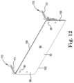
- FIG. 12 is a front perspective view of a portion of the protective enclosure of FIG. 6 showing the moveable and positionable shield attached to the coupling system (in the form of bracket assemblies in this embodiment) of the present invention that help to provide the shield with moveable and positionable functionality.
- FIG. 13 is an exploded perspective view of the moveable and positionable shield and bracket assemblies shown in FIG. 12 .
- FIG. 14 is a perspective view of a slotted hinge bracket used in each of the bracket assemblies of FIG. 12 .
- FIG. 15 is a side view of the slotted hinge bracket of FIG. 15 .
- FIG. 16 is a side perspective view of a shield bracket used in a bracket assembly of FIG. 12 , wherein a mirror image version of this shield bracket is used in the other bracket assembly of FIG. 12 .
- FIG. 17 is an exploded, side perspective view of one bracket assembly of the present invention of FIG. 12 , wherein the other bracket assembly of FIG. 12 is a mirror image version of this bracket assembly.
- FIG. 18 is an exploded, front view of the bracket assembly shown in FIG. 17 .
- FIG. 19 is a cross-section view of the bracket assembly of FIG. 22 taken along line A-A of FIG. 22 .
- FIG. 20 is a close-up, cross section view taken from area B of FIG. 19 and that shows how a bearing stud assembly engages with the slotted hinge bracket.
- FIG. 21 is a side perspective view of the bracket assembly of FIG. 17 showing the assembly in a configuration in which the moveable and positionable shield is in one of two available raised position to allow self-serve access to a food supply held in the food station of FIG. 1 .
- FIG. 22 is a side view of the bracket assembly configuration shown in FIG. 21 .
- FIG. 23 is a front perspective view of the food station of FIG. 1 in which the moveable and positionable shield is lowered into a closed configuration to prevent self-serve access to the food supply held in the food station of FIG. 1 .
- FIG. 24 is a front perspective view of the protective enclosure in the closed configuration of FIG. 23 .
- FIG. 25 is a rear perspective view of the protective enclosure in the closed configuration of FIG. 23 .
- FIG. 26 is a side view of the protective enclosure in the closed configuration of FIG. 23 .
- FIG. 27 is a side perspective view of the bracket assembly of FIG. 17 showing the assembly in a configuration in which the moveable and positionable shield is in a closed position as shown in FIG. 23 to prevent self-serve access to a food supply held in the food station of FIG. 29 .
- FIG. 28 is a side view of the bracket assembly configuration shown in FIG. 27 .
- FIG. 29 is a side perspective view of the bracket assembly of FIG. 17 showing the assembly in an alternative configuration in which the moveable and positionable shield is in the open position.
- FIG. 30 is a side view of the bracket assembly configuration shown in FIG. 29 .
- FIG. 31 is a front perspective view of an alternative embodiment of a food station incorporating principles of the present invention in which the side panel assemblies of the protective enclosure are extended to provide a larger side barrier to protect a food supply when the moveable and positionable shield is in a raised configuration.
- FIG. 32 is a side view of the embodiment of a food station shown in FIG. 31 .
- FIG. 1 through 30 A representative embodiment of a food station 10 (also referred to in the food service industry as a buffet station or food table) of the present invention is shown in FIG. 1 through 30 .
- Food station 10 is of the type that allows self-serve patron access to one or more food supplies held in food station 10 .
- food station 10 is a single-sided embodiment in the sense that self-serve patron access the food station 10 from a front side 14 .
- Access to the food supply from a rear side 16 may be blocked and/or limited only to designated service personnel such as to serve, clean, service, or maintain the food station 10 or its food supply(ies).
- Other embodiments of food station 10 may be configured so that patrons may access one or more food supplies from either the front and/or rear sides 14 and 16 and/or even from one or both sides 18 and/or 20 of food station 10 .
- food station 10 includes a base in the form of enclosed base cabinet 12 which optionally may be used for a variety of purposes such as to store food station supplies and/or to house functional food station components such as drains or other plumbing, refrigeration components, lighting, heating, sensors such as temperature sensors or food or beverage level sensors, electrical power components, and the like.
- base cabinet 12 may be fitted with casters (not shown) or other mobility devices to allow food station 10 to be more easily moved to different locations or positions. Such mobility devices may be lockable to prevent mobility once food station 10 is located or positioned in a desired manner.
- Food station 10 includes countertop 24 mounted onto base cabinet 12 .
- Countertop 24 includes upper surface 26 and one or more wells holding food supplies (not shown) in corresponding pans 32 .
- countertop 24 is configured with a single pan 32 .
- Such an embodiment provides more room on upper surface 26 to store some items, such as some food items, serving tools, eating utensils, food toppings, or the like that do not need to be deployed in pans.
- Other embodiments may include two or more pans or other serving containers and corresponding food supplies.
- such other embodiments may include from 2 to 8 sets of pans and food supplies held in corresponding countertop wells.
- Countertop 24 also includes extending portion 34 that overhangs relative to base cabinet 12 .
- Extending portion 34 provides a convenient working surface to use while interacting with food station 10 .
- a patron may use the extending portion 34 to support a food tray onto which the patron places food items from a food supply held in pan 32 .
- service personnel may use extending portion 34 to hold items used to service or maintain food station 10 .
- food station 10 includes a food protection system in the form of protective enclosure 36 that helps to protect food supply from contamination, particularly airborne contamination.
- protective enclosure 36 also is known as a “breath guard” or “sneeze guard” system.
- protective enclosure 36 includes support structure 44 , top panel 82 , side panels 88 , moveable and positionable shield, 92 , and a coupling system 110 that slideably and pivotably couples shield 92 to the protective enclosure 36 .
- Accessories for food station 10 such as heaters, lights, fans, filters, and the like may be mounted onto protective enclosure 36 as an option.
- heater 86 (see FIGS. 5 and 8 ) is attached to an underside of top panel 82 to help keep food supply warm.
- Support structure 44 includes leg assemblies 46 on each side of protective enclosure 36 .
- Each leg assembly 46 is identical to the other except for being mirror images of each other. Accordingly, details described with respect to one leg assembly 46 are also applicable to the other leg assembly 46 with this understanding.
- Each leg assembly 46 generally includes a cross beam 48 , legs 60 , pins 50 and mounting members in the form of standoffs 52 associated with attachment to top panel 82 , and pins 72 and mounting members in the form of standoffs 74 associated with attachment to side panels 88 .
- moveable and positionable shield 92 is coupled to the support structure 44 by the coupling system 110 described further below.
- Pins 50 extend inward from cross beam 48 toward the interior of the protective enclosure 36 .
- Pins 50 may be integrally formed with cross beam 48 or may be attached via a suitable attachment technique such as welding, brazing, gluing, bolting, threaded engagement, riveting, snap-fit engagement, and/or the like.
- Standoffs 52 are mounted onto the ends of pins 50 and provide attachment sites for top panel 82 . Any suitable attachment technique may be used. For example, mounting hardware such as bolts, rivets, or machine screws and associated washers may be used to attach top panel 82 to the standoffs 52 .
- Top panel 82 includes corresponding mounting apertures to accommodate such fasteners.
- Legs 60 are attached to the ends of the corresponding cross beam 48 . Legs extend from base 62 to top end 64 . A flange or escutcheon 66 is positioned on each leg 60 between the base 62 and top end 64 in order to help mount each leg to countertop 24 . A lower portion 68 of each leg 60 extends downward through countertop 24 below escutcheon 66 . An upper portion 70 of each leg 60 extends upward above countertop 24 from escutcheon 66 . Escutcheons 66 allow for adjustment of the height of upper portions 70 so that the height of the access to the food supply can be adjusted as desired.
- the figures show legs 60 attached to countertop 24 with using a through counter attachment technique. Other attachment techniques can be used. For example, the legs 60 may be attached directly to upper surface 26 without penetrating into or through countertop 24 .
- Pins 72 extend inwardly from each leg 60 in a direction generally parallel to side panels 88 and thus in the main plane of the leg assemblies 46 .
- Pins 72 may be integrally formed with legs 60 or may be attached via a suitable attachment technique such as welding, brazing, gluing, bolting, threaded engagement, riveting, snap-fit engagement, and/or the like.
- Standoffs 74 are mounted onto the ends of pins 72 and provide attachment sites for each corresponding side panel 88 . Any suitable attachment technique may be used.
- mounting hardware such as bolts, rivets, or machine screws and associated washers may be used to attach side panel 88 to the standoffs 74 .
- Each side panel 88 includes corresponding mounting apertures to accommodate such fasteners.
- Moveable and positionable shield 92 is slideably and pivotably coupled to the support structure 44 of protective enclosure 36 in a manner such that the moveable and positionable shield 92 comprises a range of motion in which the shield 92 slides and pivots to be raised and lowered in a range of motion that comprises two or more stationary positions.
- the shield 92 is moveable in the sense that the shield 92 can move through the range of motion.
- the shield 92 is positionable in the sense that the shield 92 can be positioned into two or more fixed positions within the range of motion.
- such stationary positions comprise at least a lowered shield position and at least one raised shield position. In the lowered position, access to a food supply is blocked.
- This closed configuration may be desired in a variety of circumstances such as when food station 10 is closed or when, instead of the self-service option, a service provider such as a chef serves food from station 10 to a patron according to a served mode configuration.
- An open configuration may be desired in a variety of circumstances such as to allow self-serve access to food by a patron or to allow service access to the inside of the protective enclosure 36 from the front side 14 .
- the coupling system 110 and the operation of moveable and positionable shield 92 are described further below.
- moveable and positionable shield 92 includes an outer face 94 and an inner face 96 .
- Outer face 94 generally faces outward from the inside of protective enclosure 36 while inner face 96 generally faces inward toward the inside of protective enclosure 36 .
- Moveable and positionable shield 92 further includes a first end 98 proximal to a corresponding first leg assembly 46 and a second end 100 that is proximal to a corresponding second leg assembly 46 .
- Moveable and positionable shield 92 includes leading or front edge 102 extending from first end 98 to second end 100 .
- Edge 102 is leading or towards the front in the sense that this edge 102 is closest to the user on the front side 14 of station 10 that is guarded by the shield 92 when shield 92 is in an open configuration. Edge 102 also leads the motion of shield 92 when shield 92 is lowered into a closed configuration.
- Moveable and positionable shield 92 includes trailing or rear edge 104 extending from first end 98 to second end 100 . Edge 104 is trailing or towards the rear in the sense that this edge 104 is closer to the rear side 16 of station 10 when the shield 92 is in an open configuration. Edge 104 also trails the motion of shield 92 when shield 92 is lowered into a closed configuration.
- Moveable and positionable shield 92 also includes suitable mounting apertures through the faces 94 and 96 . These mounting apertures accommodate hardware 95 used to attach shield to the coupling system 110 . Similar apertures and hardware are used with respect to top panel 82 and side panels 88 .
- Each of panels 82 or 88 , or shield 92 can be made from a wide range of materials such as glass materials, polymer materials, and the like. Desirably, one or more of these are transparent to allow the contents of food station 10 to be viewed through the panels or shield. In on suitable embodiment, one or more of panels 82 or 88 , or shield 92 are made from tempered glass, preferably 3 ⁇ 8 inch thick tempered glass.
- Coupling system 110 is shown throughout the Figures, but is shown in the most detail in FIGS. 12 through 22 , and 27 to 30 .
- Coupling system 110 in the form of bracket assemblies 111 is used to slideably and pivotably couple the positionable and moveable shield 92 to the protective enclosure 36 .
- coupling system couples the bracket assemblies 111 to the support structure 44 , although other embodiments may involve coupling to other enclosure components such as top panel 82 and/or side panels 88 .
- One bracket assembly 111 connects first end 98 of shield 92 to the support structure 44 .
- Another bracket assembly 111 connects second end 100 of shield 92 to the support structure 44 .
- Each bracket assembly 111 is identical to the other except for being mirror images of each other. Accordingly, details described with respect to bracket assembly 111 are also applicable to the other bracket assembly 111 with this understanding.
- Each bracket assembly 111 generally includes a first bracket in the form of slotted hinge bracket 112 and a second bracket in the form of shield bracket 174 .
- Slotted hinge bracket 112 is attached to support structure 44 and includes slot features (described further below) that help to guide moveable and positionable shield 92 through its range of motion. These features include functionality that also helps to hold shield 92 in fixed positions including at least one lowered configuration to at least partially block access to the interior of the protective enclosure 36 and at least one raised or open configuration that allows access to the interior of the protective enclosure 36 .
- Shield bracket 174 is attached to the moveable and positionable shield 92 and further incorporates at least one bearing surface that slideably and pivotably engages the slot features of the slotted hinge bracket 111 .
- Slotted hinge bracket 112 includes body 114 formed from leg 116 , arm 124 , and shoulder plate 132 . As illustrated, these components are integral to a single bracket plate. In some embodiments, these may be separate components that are coupled together.
- Leg 116 extends from base 118 at a lower end to top end 120 proximal to shoulder plate 132 . A portion of leg 116 at top end 120 projects above arm 124 in order to provide a mounting tab 122 to attach bracket 112 to support structure 44 . Arm 124 extends from first end 126 proximal to shoulder plate 132 to second end 128 . Mounting tab 130 extends upward from second end 128 . Like mounting tab 122 , mounting tab 130 also provides a surface to attach slotted hinge bracket 112 to the support structure 44 . Tabs 122 and 130 can be connected to the support structure 44 in any suitable way such as glue, rivets, bolts, threaded engagement, snap-fit engagement, brazing, welding, or the like. In some embodiments, brazed or welded connections would be suitable. In other embodiments, fastening techniques are used to allow the bracket assemblies 111 to be removed or installed on demand to adjust the configuration of station 10 for different uses.
- leg 116 When attached to the support structure, leg 116 is positioned generally toward and along a nearby leg 60 on the front side 14 of food station 10 , while the second end 128 of arm 124 is positioned relatively more in a direction toward the rear side 16 along cross beam 48 .
- Arm 124 has a length, though, such that it only extends partway into the interior of the protective enclosure 36 , and desirably less than halfway into the protective enclosure 36 . Configured in this desirable way, the dimensions of food station 10 and its components are such that a second moveable and positionable shield and coupling system of the same design could be attached to the rear side 16 of station 10 to allow double sided self-serve access, if desired.
- the attachment of the coupling system 110 to the support structure 44 could even be removable and thus modular so that the configuration could be changed as desired to provide food station 10 with the ability to be presented as either a single sided, self-serve station or a double sided, self-serve station.
- Slotted hinge bracket 112 has a slot system 134 including first slot 136 and second slot 148 .
- the first slot 136 slideably and pivotably guides the shield bracket 174 in a manner effective to slideably and pivotably guide a rearward portion of the moveable and positionable shield 92 through the range of motion.
- the first slot 136 also includes features to help hold moveable and positionable shield 92 in fixed positions.
- First slot 136 engages a bearing surface associated with the shield bracket 174 in order to guide a rearward portion of the moveable shield 92 proximal to the trailing edge 104 .
- first slot 136 has a first or leading end 138 proximal to the front side 14 of station 10 when installed in station 10 .
- the first slot 136 also has a second end 140 proximal to the second end 128 of arm 124 .
- a hook portion 142 of first slot 136 provides a pocket to help hold the moveable and positionable shield in a closed configuration in a manner described further below.
- First slot 136 has a slot axis 144 that is slanted downward in a direction from the front side 14 toward the rear side 16 at a modest angle relative to a horizontal reference line 146 . In some embodiments, this downward slant may be at an angle in the range from 1 to 20 degrees below the horizontal reference line 146 .
- the slant allows gravity to help assist in placing the moveable and positionable shield into one or more of the raised positions.
- the downward slant allows gravity to help counteract the weight of shield 92 as it is lowered into a closed configuration.
- the result is that the shield 92 serves as its own counterweight to some degree when being raised and lowered.
- the apparent weight of the moveable and positionable shield 92 is less than its actual weight due to this assist.
- the second slot 148 generally includes a first slot leg 150 and a second slot leg 160 joined at a rounded slot apex 172 .
- First slot leg 150 extends from a bottom end 152 proximal to base 118 of leg 116 to a top end 154 .
- First slot leg 150 has a slot axis 156 that is slightly canted at an angle with respect to a vertical reference line 158 .
- the angle, ⁇ , at which the slot axis 156 is canted with respect to the vertical reference line desirably is in a range from 1 to 10 degrees.
- the canting of first slot leg 150 helps to make the raising and lowering action of shield 92 smoother.
- Second slot 148 slideably and pivotably engages the shield bracket 174 in a manner effective to slideably and pivotably guide a leading portion of the moveable and positionable shield 92 proximal to the leading edge 102 through the range of motion.
- Second slot leg 160 extends from a first end 162 at apex 172 to a second end 164 .
- Apex 172 joins second slot leg 160 and first slot leg 150 with a smooth contour configured to provide a smooth range of motion as a bearing surface on the shield bracket 174 is guided from first slot leg 150 into second slot leg 160 and vice versa.
- Second slot leg 160 has a slot axis 170 that is oriented at an acute angle, ⁇ , with respect to slot axis 156 of the first slot leg 150 .
- this acute angle, ⁇ is in the range from 20 degrees to 80 degrees, more preferably 25 degrees to 60 degrees.
- slot axis 170 is nonparallel with respect to slot axis 144 of the first slot 136 and further is slanted even more steeply downward with respect to the horizontal reference line 146 as compared to slot axis 144 .
- Second slot leg 160 helps to lower and more securely position moveable and positionable shield 92 into one or more, fixed, raised configurations.
- Second slot leg 160 includes one or more features that help to position moveable and positionable shield 92 in these one or more raised positions.
- such features may include one or more pockets into which engaged portion(s) of the shield bracket 174 can be lowered and captured to hold the leading edge 102 of shield 92 in a desired raised position.
- second slot leg 160 is configured with two such pockets 166 and 168 corresponding to first and second raised positions, respectively.
- First pocket 166 extends downward from second slot leg 160 in a manner such that the first pocket 166 is generally parallel to the first slot leg 150 .
- Second pocket 168 is both deeper and canted inward in a non-parallel fashion toward the first slot leg 150 .
- Other embodiments of second slot leg 160 may be configured with only one pocket corresponding to a single raised shield position, or with three or more pockets to provide 3 or more corresponding raised configurations.
- the coordinated guidance provided by the slots 136 and 148 provides easy and smooth operation when raising and lowering shield 92 .
- the hook 142 and pockets 166 and 168 in cooperation with gravity, provide firm, fixed positions.
- the “reverse J” configuration of second slot 148 helps to prevent accidental shutting of shield 92 when shield 92 is fixed in one of the two open positions.
- the user In order to close the shield 92 from one of the open positions, in a first stage, the user would have to lift up on shield 92 while also pushing the shield 92 further back into slot 136 . Thereafter, in a second stage, with the corresponding bearing surface of the bearing study assembly in slot 148 free of the pocket 166 or 168 , the user could only then lower shield 92 to the closed configuration.
- the downward slant of slot 136 helps ease the motion as shield 92 is lowered.
- the slot and pocket design incorporated into the slotted hinge bracket 112 incorporates a two-stage mechanism that holds the shield 92 in an open configuration.
- the downward slope of the second slot leg 160 helps to establish more secure, open positions as well. This slope prevents a mere pull from being able to close the shield 92 from an open configuration.
- the slot design also contributes to the function that closing the shield 92 requires that the shield 92 is lifted and pushed back and only then lowered to close the shield 92 .
- Shield bracket 174 is generally shown throughout the figures but is shown in more detail in FIGS. 16 through 22 and 27 to 28 .
- Shield bracket 174 generally includes body 176 , pins 194 , standoffs 202 , and bearing stud assemblies 206 .
- Body 176 extends from a first or leading end 178 to a second or trailing end 180 .
- First end 178 generally is relatively proximal to the leading edge 102 of shield 92
- second end 180 is relatively proximal to the trailing edge 104 of shield 92 .
- Body 176 preferably has wider portions 182 and 184 that help to strengthen and stiffen body 176 at sites where body 176 will be coupled to moveable and positionable shield 92 via pins 194 and mounting members or standoffs 202 .
- Moveable and positionable shield 92 includes apertures configured to accommodate hardware 95 , such as bolts, machine screws, rivets, or the like, that attach shield 92 to the standoffs 202 .
- each pin 194 includes a first end 195 attached to body 176 by any suitable fastening technique. Second ends 196 of pins 194 are attached to corresponding standoffs 202 by any suitable fastening technique. Standoffs 202 include an aperture for attachment to a corresponding pin 194 and an aperture 197 to receive hardware to attach each standoff 202 to shield 92 . Examples of suitable fastening techniques used to assemble the components of shield bracket 174 include threaded engagement, bolts, machine screws, glue, brazing, welding, combinations of these, and the like.
- shield bracket 174 incorporates a bearing stud assembly 206 that helps to guide a leading portion of shield 92 proximal to leading edge 102 and an additional bearing stud assembly 206 that helps to guide a trailing portion of shield 92 proximal to trailing edge 104 .
- the bearing stud assembly 206 proximal to leading edge 102 is slideably and pivotably guided by the second slot 148 .
- the bearing stud assembly proximal to trailing edge 104 is slideably and pivotably guided by the first slot 136 . In practical effect, this configuration means that the first slots 136 in the bracket assemblies 111 guide the rearward portion of shield 92 while the second slots 148 of bracket assemblies 111 guide the leading portion of shield 92 .
- Each bearing stud assembly 206 generally includes a sleeve washer 208 , stud pin 214 , and an additional washer 222 .
- Sleeve washer 208 includes a shaft 209 and head 212 .
- Sleeve washer advantageously is made from a material such as nylon to provide a low friction engagement with the slots 136 and 148 .
- the entire assembly 206 also is easy to clean, is durable and long-lasting, and does not need lubrication that otherwise could generate contamination of a food supply.
- Shaft 209 includes outer bearing surface 210 that slideably and pivotably engages a corresponding slot in the corresponding slotted hinge bracket 112 .
- a through bore 211 extends though sleeve washer 208 .
- Stud pin 214 includes a shaft 216 and a head 220 .
- Base 217 of shaft 216 is configured to slideably and rotatably fit inside through bore 211 .
- Threaded end 218 is configured to threadably engage threaded mounting apertures 192 in the body
- a sleeve washer 208 is fitted though each slot 136 and 148 of a corresponding slotted hinge bracket 112 .
- the outer bearing surface 210 of each shaft 209 of a sleeve washer 208 is sized to provide a small clearance gap 224 ( FIG. 20 ) with its corresponding slot so that the bearing surface 210 can slide and pivot freely without undue friction while at the same time minimizing too much free play so that movement of a bearing stud assembly 206 within its corresponding slot is smooth and precise.
- a stud pin 214 is then inserted through each of the sleeve washers 208 , with the threaded end 218 of each stud pin 214 being threaded into a corresponding aperture 192 in the body 176 of the shield bracket 174 through a corresponding washer 222 .
- the threaded end 218 of the stud pin 214 is tightened in the aperture 192 , the wider base 217 clamps against the washer 222 and surface of body 176 .
- bearing study assembly 206 associated with the leading edge 102 of the shield 92 is fit through the second slot 148 of the slotted hinge bracket 112 .
- a second bearing stud assembly 206 associated with the trailing edge 104 of the shield 92 is fit through the first slot 136 of the slotted hinge bracket 112 .
- each shield bracket 174 and hence the moveable and positionable shield 92 attached to the shield brackets 174 , to move through a range of motion relative to the slotted hinge bracket 112 .
- the bearing stud assemblies 206 of each shield bracket 174 are guided in coordinated fashion by the slots 136 and 148 in the slotted hinge bracket 112 .
- the bearing stud assembly 206 coupled to a second slot 148 is lifted up the first slot leg 150 , though the apex 172 , and then down the second slot leg 160 , the bearing stud assembly 206 coupled to the first slot 136 traverses rearward in a coordinated fashion along the first slot 136 in a direction generally from the front side 14 of station 10 to the rear side 16 .
- the bearing stud assembly 206 coupled to a second slot 148 is lifted up the second slot leg 160 , though the apex 172 , and then down the first slot leg 150 , the bearing stud assembly 206 coupled to the first slot 136 traverses forward in a coordinated fashion along the first slot 136 in a direction generally from the rear side 16 of station 10 to the front side 14 .
- FIGS. 21 to 30 show in more detail how the coordinated movement of bearing stud assemblies 206 in slots 136 and 148 allow the moveable and positionable shield 92 to be moved through a range of motion and positioned in raised and lowered positions.
- a bracket assembly 111 is in a configuration in which the moveable shield is in a fixed, raised position corresponding to the configuration of food station 10 shown in FIGS. 1 to 8 .
- a first bearing stud assembly 206 proximal to the leading edge 102 of shield 92 is lowered into and held in pocket 166 .
- a second bearing stud assembly 206 more proximal to the trailing edge 104 is positioned towards and supported by a rearward portion of first slot 136 .
- gravity holds the first bearing stud assembly 206 in pocket 166 .
- a latch, chain, pin, depressible button, or the like may be used if desired to restrain the assembly 206 in the pocket 166 unless the security is released.
- Another, similar raised, open configuration (See FIGS. 27 and 28 ) could be achieved by placing the first bearing stud assembly 206 into the second pocket 168 .
- Different raised configurations may be desirable depending upon how food station 10 is to be used.
- the positioning and use of protective enclosures is subject to specific regulations.
- the NSF standards (promulgated by NSF International, a public health and safety organization) are one set of rules that may apply to food service operations in the United States.
- regulations There also may different versions of regulations that may be applicable.
- one version of NSF standards may be applicable to one food setting, while a different version of NSF standards may be applicable to another food setting.
- Having multiple pockets such as pockets 166 and 168 allows protective enclosure 36 to be useful in different settings without having to change hardware or secure a different food station.
- the use of multiple pockets is optional, however, and some embodiments of food station 10 may include only one pocket configuration suitable for a desired use.
- FIGS. 23 to 30 show in more detail another manner by which the coordinated movement of bearing stud assemblies 206 in slots 136 and 148 allow the moveable and positionable shield 92 to be moved through a range of motion and positioned in a lowered position.
- a bracket assembly 111 is in a configuration such that a first bearing stud assembly 206 proximal to the leading edge 102 of shield 92 is lowered into the first slot leg 150 and supported at the bottom end 152 .
- a second bearing stud assembly 206 engaged with the first slot 136 is positioned forward and captured at the bottom of the pocket or hook 142 in the leading end 138 .
- FIGS. 23 to 26 show how the moveable and positionable shield 92 is lowered and blocks access to the interior of protective enclosure 36 in this configuration.
- FIGS. 31 and 32 An optional modification of food station 10 is shown in FIGS. 31 and 32 that enhances the ability of protective enclosure 36 to form a barrier against airborne contamination.
- the moveable and positionable shield 92 extends outward toward front side 14 beyond the barrier protection provided by side panels 88 .
- Food station 10 is modified to augment the barrier protection under the raised shield 92 .
- side panels 88 of FIG. 1 are replaced with side panels 232 that include extension wings 234 to more fully establish a side barrier when shield 92 is raised.
- Extension wings 234 are shown as being integral with side panels 232 , but these may be separate components that may be installed or removed on demand.
Landscapes
- Baking, Grill, Roasting (AREA)
Abstract
Description
-
- a) a support structure;
- b) a protective enclosure comprising a moveable and positionable shield, said moveable and positionable shield comprising a first shield end and a second shield end, wherein each of the first and second shield ends is slideably and pivotably coupled to the support structure in a manner such that the moveable shield comprises a range of motion in which the shield slides and pivots to be raised and lowered in a range of motion that comprises two or more stationary positions comprising at least a lowered shield position and a raised shield position;
- c) a first bracket assembly that slideably and pivotably couples the first shield end to the support structure; and
- d) a second bracket assembly that slideably and pivotably couples the second shield end to the support structure;
-
- a) a countertop;
- b) a base supporting the countertop; and
- c) a food protection system according to the first aspect that is incorporated into the food station in a manner such that the protective enclosure provides a barrier between the countertop and at least a portion of the ambient environment.
-
- a) a support structure;
- b) a protective enclosure comprising a moveable and positionable shield, said moveable and positionable shield comprising a first shield end and a second shield end, wherein each of the first and second shield ends is slideably and pivotably coupled to the support structure in a manner such that the moveable shield comprises a range of motion in which the shield slides and pivots to be raised and lowered in a range of motion that comprises two or more stationary positions;
- c) a first bracket assembly that slideably and pivotably couples the first shield end to the support structure; and
- d) a second bracket assembly that slideably and pivotably couples the second shield end to the support structure; and
wherein each of the first and second bracket assemblies comprises first and second slots that cooperatively guide corresponding first and second bearing surfaces.
-
- a) a countertop;
- b) a base supporting the countertop; and
- c) a food protection system according to the third aspect that is incorporated into the food station in a manner such that the protective enclosure provides a barrier between the countertop and at least a portion of the ambient environment.
-
- a) a support structure;
- b) a protective enclosure comprising a moveable and positionable shield, said moveable and positionable shield comprising a first shield end and a second shield end, wherein each of the first and second shield ends is slideably and pivotably coupled to the support structure in a manner such that the moveable shield comprises a range of motion in which the shield slides and pivots to be raised and lowered in a range of motion that comprises two or more stationary positions comprising at least a lowered shield position and a raised shield position;
- c) a first bracket assembly that slideably and pivotably couples the first shield end to the support structure; and
- d) a second bracket assembly that slideably and pivotably couples the second shield end to the support structure; and
-
- i) the first slot slideably and pivotably engages the first bearing surface in a manner effective to slideably and pivotably guide a rearward portion of the moveable and positionable shield, and wherein the first slot includes a first slot axis that is sloped downward at an angle relative to a horizontal reference line; and
- ii) the second slot slideably and pivotably engages the second bearing surface in a manner effective to slideably and pivotably guide a leading portion of the moveable and positionable shield, and wherein the second slots comprises first and second slot legs acutely joined proximal to the top of the first slot leg at an apex, wherein the first slot leg is substantially vertical and the second slot leg has a second slot leg axis that is sloped downward relative to the horizontal reference line more steeply than the first slot axis.
-
- a) a countertop;
- b) a base supporting the countertop; and
- c) a food protection system according to the fifth aspect that is incorporated into the food station in a manner such that the protective enclosure provides a barrier between the countertop and at least a portion of the ambient environment.
Claims (21)
Priority Applications (1)
| Application Number | Priority Date | Filing Date | Title |
|---|---|---|---|
| US16/533,306 US11684184B2 (en) | 2018-08-10 | 2019-08-06 | Protection guard having moveable and positionable shield useful for food stations in the food service industry |
Applications Claiming Priority (2)
| Application Number | Priority Date | Filing Date | Title |
|---|---|---|---|
| US201862717114P | 2018-08-10 | 2018-08-10 | |
| US16/533,306 US11684184B2 (en) | 2018-08-10 | 2019-08-06 | Protection guard having moveable and positionable shield useful for food stations in the food service industry |
Publications (2)
| Publication Number | Publication Date |
|---|---|
| US20200046146A1 US20200046146A1 (en) | 2020-02-13 |
| US11684184B2 true US11684184B2 (en) | 2023-06-27 |
Family
ID=69405181
Family Applications (1)
| Application Number | Title | Priority Date | Filing Date |
|---|---|---|---|
| US16/533,306 Active 2041-03-11 US11684184B2 (en) | 2018-08-10 | 2019-08-06 | Protection guard having moveable and positionable shield useful for food stations in the food service industry |
Country Status (1)
| Country | Link |
|---|---|
| US (1) | US11684184B2 (en) |
Families Citing this family (7)
| Publication number | Priority date | Publication date | Assignee | Title |
|---|---|---|---|---|
| US11134321B2 (en) * | 2016-08-04 | 2021-09-28 | The Vollrath Company, L.L.C. | Wireless temperature probe |
| WO2019078910A1 (en) * | 2017-10-16 | 2019-04-25 | The Vollrath Company, L.L.C. | Adjustable breath guard |
| US11684184B2 (en) | 2018-08-10 | 2023-06-27 | The Vollrath Company, L.L.C. | Protection guard having moveable and positionable shield useful for food stations in the food service industry |
| US11576505B2 (en) | 2019-02-06 | 2023-02-14 | The Vollrath Company, Llc | Food station with repositionable shield |
| US11491252B1 (en) * | 2020-05-15 | 2022-11-08 | William F. Timme | Pathogen containment shield |
| US20220064944A1 (en) * | 2020-09-01 | 2022-03-03 | Frank Eucalitto | Portable Counter Partition System |
| US12262821B2 (en) | 2021-12-23 | 2025-04-01 | The Vollrath Company, L.L.C. | Adjustable breath guard |
Citations (128)
| Publication number | Priority date | Publication date | Assignee | Title |
|---|---|---|---|---|
| US443350A (en) | 1890-12-23 | Hubert j | ||
| US827950A (en) | 1902-05-16 | 1906-08-07 | Caxton Company | Hinge for school-desk seats. |
| US1023789A (en) | 1911-09-21 | 1912-04-16 | Solomon Himmel | Display-rack. |
| US1075334A (en) | 1913-04-16 | 1913-10-14 | William H Cobb | Show-case. |
| US1288665A (en) | 1918-03-28 | 1918-12-24 | Herbert Page | Sliding door or flap for bookcases, cabinets, and like furniture. |
| US1358262A (en) | 1919-10-27 | 1920-11-09 | Warren S Sumner | Antiglare attachment |
| US1431371A (en) | 1921-01-03 | 1922-10-10 | Fillmore Company W | Show case |
| US1644675A (en) | 1925-12-23 | 1927-10-11 | Paul J Daemicke Company | Display case |
| US1705237A (en) * | 1927-03-07 | 1929-03-12 | Elvah O Bulman | Display rack |
| US1725867A (en) | 1929-08-27 | Show case | ||
| US2767003A (en) | 1948-06-22 | 1956-10-16 | Emil Greiner Company | Joint for universally adjustable frame |
| US3426993A (en) * | 1966-03-28 | 1969-02-11 | Rune Oskar Johansson | Shelf brackets |
| US3554416A (en) | 1968-02-21 | 1971-01-12 | Bott John Anthony | Vehicle luggage rack |
| US3561713A (en) * | 1969-01-15 | 1971-02-09 | Kason Hardware Corp | Angularly adjustable shelf bracket |
| US3795379A (en) * | 1972-09-13 | 1974-03-05 | Ebsco Ind Inc | Adjustable shelf support |
| US3921539A (en) * | 1974-12-31 | 1975-11-25 | Thomson Leeds Co | Shelf support structure |
| US4216844A (en) | 1977-07-20 | 1980-08-12 | Zarges Leichtbau Gmbh | Fitting for joints of ladder sections |
| US4230414A (en) | 1977-10-18 | 1980-10-28 | Uop Inc. | Ratchet-action hinge device |
| FR2504216B3 (en) | 1981-04-16 | 1984-02-10 | Humery Freres Sa | |
| US4448337A (en) | 1982-05-06 | 1984-05-15 | Masco Corporation | Article carrier |
| US4469261A (en) | 1982-05-06 | 1984-09-04 | Masco Corporation | Article carrier with adjustably positionable bracket |
| US4500020A (en) | 1982-05-06 | 1985-02-19 | Masco Corp. | Article carrier with adjustably positionable bracket |
| US4506408A (en) | 1982-09-30 | 1985-03-26 | Brown Dwight C | Ratchet hinge structure |
| US4608773A (en) | 1985-02-14 | 1986-09-02 | Royston Corporation | Kiosk display unit |
| US4658983A (en) | 1985-05-28 | 1987-04-21 | Royston Corporation | Cup dispenser |
| US4660885A (en) | 1985-08-02 | 1987-04-28 | Firma August Froscher Gmbh & Co. K.G. | Adjusting mechanism for the step-wise locking height adjustment of backrest of work chair |
| US4662114A (en) | 1985-12-30 | 1987-05-05 | Royston Corporation | Sheet metal door for cabinets and the like |
| USD293985S (en) | 1985-05-06 | 1988-02-02 | Royston Corporation | Display stand |
| US4757769A (en) | 1987-07-27 | 1988-07-19 | Royston Corporation | Shelving unit |
| USD297490S (en) | 1985-12-31 | 1988-09-06 | Royston Corporation | Cabinet door |
| US4773543A (en) | 1987-04-08 | 1988-09-27 | Royston Corporation | Cigarette merchandizing device |
| USD298596S (en) | 1986-06-09 | 1988-11-22 | Royston Corporation | Cup dispenser collar |
| US4829611A (en) | 1988-04-12 | 1989-05-16 | Robert Fireman | Sofa bed recliner |
| USD301665S (en) | 1986-04-21 | 1989-06-20 | Royston Corporation | Pastry rack |
| USD302221S (en) | 1986-04-14 | 1989-07-18 | Royston Corporation | Foodservice counter with sneeze guard |
| US4852954A (en) | 1988-05-26 | 1989-08-01 | Royston Corporation | Step-front cabinet with improved overhanging cover and tray retainer |
| USD303190S (en) | 1986-06-09 | 1989-09-05 | Royston Corporation | Cup protector attachment to a cabinet |
| USD304535S (en) | 1987-05-29 | 1989-11-14 | Royston Corporation | Cup dispenser housing |
| US4881660A (en) | 1988-05-03 | 1989-11-21 | Royston Corporation | Jumbo cup dispenser |
| US4909491A (en) * | 1989-02-08 | 1990-03-20 | Cheng Wen H | Saw platform and workbench |
| US4915334A (en) | 1989-07-28 | 1990-04-10 | Royston Corporation | Captive nut base adjusting device |
| USD309540S (en) | 1989-05-16 | 1990-07-31 | Royston Corporation | Sneeze guard |
| USD311837S (en) | 1989-07-28 | 1990-11-06 | Royston Corporation | Transparent condiment tray |
| USD314876S (en) | 1989-07-28 | 1991-02-26 | Royston Corporation | Combined storage and cup dispenser unit |
| USD324737S (en) | 1989-05-18 | 1992-03-17 | Royston Corporation | Canopy for a convenience store food preparation center |
| USD337462S (en) | 1992-02-18 | 1993-07-20 | Lavaute Peter A | Sneeze guard |
| CA2153439A1 (en) | 1994-07-08 | 1996-01-09 | Peter A. Lavaute | Sneeze guard |
| US5664268A (en) | 1995-10-13 | 1997-09-09 | Chester Stoler | Futon frame |
| US5699614A (en) | 1995-08-04 | 1997-12-23 | Garneau, Sr.; John P. | Attachable and removable handle for food serving utensils |
| US5749480A (en) * | 1997-01-17 | 1998-05-12 | Stamford Investments, Inc. | Pivotal display rack |
| US6115921A (en) | 1995-08-04 | 2000-09-12 | Safe Food Systems, Inc. | Attachable and removable handle for food serving utensils |
| US6132018A (en) | 1999-03-09 | 2000-10-17 | Andrew H. McGrath | Adjustable sneezeguard apparatus |
| US6267111B1 (en) | 1999-01-25 | 2001-07-31 | William Hendricks Burton | Portable self-contained mobile vending unit |
| US6290025B1 (en) | 2000-05-01 | 2001-09-18 | Terry S. Lynn | Railroad theme restaurant and food delivery system and method of making same |
| US6343406B1 (en) | 2000-08-14 | 2002-02-05 | Tom Yeh | Hinge on ladder |
| US6390424B1 (en) | 2000-07-13 | 2002-05-21 | Margo Kidushim | Accessory support device and method |
| US20020096976A1 (en) * | 2001-01-19 | 2002-07-25 | Matus Jose Orlando | Adjustable food guard apparatus |
| US20030047086A1 (en) * | 2001-09-13 | 2003-03-13 | Matus Jose Orlando | Modular food guard apparatus and systems and methods of use thereof |
| USD472083S1 (en) | 2002-09-09 | 2003-03-25 | English Douglas A | Sneeze guard |
| US20030057810A1 (en) | 2000-05-26 | 2003-03-27 | Brass Smith Inc. | Sneeze guards with lights |
| US6588863B1 (en) | 2000-05-26 | 2003-07-08 | Brass Smith, Inc. | Sneeze guards and methods for their construction and use |
| US6612124B1 (en) | 2002-05-10 | 2003-09-02 | T3B, Inc., A California Corporation | Simplified food-preparation table with easy accessibility of temperature-protected food |
| USD497739S1 (en) | 2003-07-23 | 2004-11-02 | Douglas A. English | Sneeze guard with shelf |
| US20040226903A1 (en) | 2003-05-13 | 2004-11-18 | Wang Chang Chou | Rotatable and adjustable display shelf device |
| DE10320528A1 (en) * | 2003-04-29 | 2004-12-02 | Hakemann, Edgar, Dip.-Ing. | Shop counter with lift-up front panel has guide path with direction change to allow glass panel to move from self-service to serviced position of counter |
| US20050061585A1 (en) * | 2003-09-15 | 2005-03-24 | Duke Manufacturing Company | Product server with breath guard |
| US7067773B2 (en) | 2003-05-14 | 2006-06-27 | Bsi Properties, Inc. | Food warming device and methods for its manufacture |
| US20060175940A1 (en) | 2005-02-10 | 2006-08-10 | English Douglas A | Adjustably positionable sneeze guard |
| US7210742B2 (en) | 2005-03-22 | 2007-05-01 | Yao-Chuan Wu | Distance adjustment device for chair |
| USD543780S1 (en) | 2005-03-15 | 2007-06-05 | Triteq Lock And Security, Llc | Beverage fountain keypad |
| JP2007159882A (en) | 2005-12-15 | 2007-06-28 | Nakano Refrigerators Co Ltd | Sneeze guard device of open showcase |
| US20070236112A1 (en) | 2006-04-11 | 2007-10-11 | Lawrence Metal Products, Inc. | Sneeze Guard |
| USD575560S1 (en) | 2005-02-10 | 2008-08-26 | English Douglas A | Adjustably positionable sneeze guard |
| US20090224583A1 (en) | 2005-07-27 | 2009-09-10 | Aisin Seiki Kabushiki Kaisha | Lock device and seat reclining apparatus |
| US7631575B2 (en) | 2005-05-17 | 2009-12-15 | Gard Paul D | Adjustable rotary locking and unlocking device |
| US20100045149A1 (en) * | 2008-08-24 | 2010-02-25 | English Douglas A | Adjustment apparatus for sneeze guard |
| US7784398B2 (en) | 2005-04-19 | 2010-08-31 | Elemental Ideas, Llc | Food protector apparatus that attaches to a drop-in food pan and method |
| JP2011012750A (en) | 2009-07-02 | 2011-01-20 | Oiles Corp | One-way rotating damper, hinge mechanism with the damper, opening and closing mechanism and range hood |
| US7895953B2 (en) | 2005-10-25 | 2011-03-01 | Elemental Ideas, L.L.C. | Structural support for a food guard apparatus |
| US20110080075A1 (en) * | 2009-10-02 | 2011-04-07 | Matus Jr Jose Orlando | Convertible food guard system with adjustable side panels |
| US20110169384A1 (en) | 2010-01-13 | 2011-07-14 | Brass Smith, LLC (Subsidiary of Kevry Corp.) | Food shield |
| USD649865S1 (en) | 2011-02-02 | 2011-12-06 | English Douglas A | Sneeze guard bracket |
| US8112920B2 (en) | 2008-07-03 | 2012-02-14 | 7-Eleven, Inc. | Rolling information display for roller grill |
| US8128306B2 (en) | 2008-09-29 | 2012-03-06 | Technogym S.P.A. | Regulating device |
| US20120200207A1 (en) | 2011-02-07 | 2012-08-09 | Brass Smith, Llc | Adjustable food shield |
| US8302919B1 (en) | 2010-02-03 | 2012-11-06 | Mcgrath Andrew H | Adjustable bracket assembly |
| US8544112B2 (en) | 2011-04-12 | 2013-10-01 | Nigel Gosine | Guard and method of protecting food from germs and contamination |
| US8898862B1 (en) | 2014-04-29 | 2014-12-02 | Andrew H. McGrath | Push-button, locking hinge assembly |
| US20140366751A1 (en) | 2013-06-18 | 2014-12-18 | Brass Smith, LLC (BSI Designs) | Food service equipment and systems |
| US8925153B1 (en) | 2014-06-23 | 2015-01-06 | Andrew H. McGrath | Pull-button, locking hinge assembly |
| US8925172B2 (en) | 2013-02-05 | 2015-01-06 | Douglas A. English | Mounting fixture and method for using same |
| US8973876B1 (en) | 2010-02-03 | 2015-03-10 | Andrew H. McGrath | Adjustable bracket assembly |
| US9010883B2 (en) | 2013-03-13 | 2015-04-21 | Advance Tabco, Inc. | Food shield having a single-sided locking mechanism |
| US9062483B1 (en) | 2014-06-18 | 2015-06-23 | Andrew H. McGrath | Free-wheeling hinge assembly |
| US9144329B1 (en) | 2014-06-17 | 2015-09-29 | Andrew H. McGrath | Adjustable filler bracket assembly for sneeze guards |
| CN204704255U (en) | 2015-01-26 | 2015-10-14 | 杭州安费诺飞凤通信部品有限公司 | The unidirectional friction shaft hinge of easy switch and mobile electronic product terminal |
| US20150289641A1 (en) | 2014-04-14 | 2015-10-15 | Mustafa A. Ergun | Height adjustable desktop work surface |
| US9161639B1 (en) | 2014-05-09 | 2015-10-20 | The Vollrath Company, L.L.C. | Folding breath guard |
| US9249827B2 (en) | 2012-12-21 | 2016-02-02 | Taco Metals, Inc. | Hinge employing a ratchet for an upholstery seat |
| US20160073795A1 (en) | 2014-09-17 | 2016-03-17 | Jose Orlando Matus, Jr. | Modular Food Guard System |
| US9291188B2 (en) | 2014-02-05 | 2016-03-22 | Douglas A. English | Mounting fixture and method for using same |
| US9326621B1 (en) | 2015-04-02 | 2016-05-03 | Metal Masters Foodservice Equipment Co., Inc. | Food shield |
| US9339131B1 (en) | 2015-04-02 | 2016-05-17 | Metal Masters Foodservice Equipment Company, Inc. | Food shield |
| USD756759S1 (en) | 2015-02-18 | 2016-05-24 | Brass Smith Llc | Support column for a food shield |
| US9399882B1 (en) | 2014-04-25 | 2016-07-26 | Andrew H. McGrath | Portable, adjustable panel assembly |
| US20160331155A1 (en) | 2015-02-12 | 2016-11-17 | Brass Smith Llc | Food shield detent mechanism |
| US9516958B1 (en) | 2015-04-02 | 2016-12-13 | Metal Masters Foodservice Equipment Company, Inc. | Adjustable food shield |
| US9557004B1 (en) | 2014-04-29 | 2017-01-31 | Andrew H. McGrath | Adjustable bracket assembly |
| US9723935B1 (en) | 2015-04-02 | 2017-08-08 | Metal Masters Foodservice Equipment Co., Inc. | Adjustable food shield |
| US9777521B2 (en) | 2012-12-11 | 2017-10-03 | Koninklijke Philips N.V. | Enhanced hinge and method for pivotally and removably connecting a member with a structure |
| US9782022B2 (en) | 2015-02-12 | 2017-10-10 | Brass Smith Llc | Adjustable food shield with detents |
| US10024090B2 (en) | 2016-09-02 | 2018-07-17 | Microsoft Technology Licensing, Llc | Removable couplers for assembly of an integrated multi-pivot hinge module |
| US10047789B1 (en) | 2017-05-05 | 2018-08-14 | Ms. Carita Safetruck, Inc | Locking pivot joint |
| US10058199B1 (en) | 2017-10-10 | 2018-08-28 | Kenneth Perry | Food tray enclosure |
| US20180242760A1 (en) | 2017-02-24 | 2018-08-30 | PMG Ventures, Inc. | Food display friction hinge |
| US10100571B2 (en) | 2014-12-29 | 2018-10-16 | Van Parys, Remi Emiel | Concealed hinge for a pivoting window or pivoting door and window equipped therewith |
| US10174534B2 (en) | 2015-01-27 | 2019-01-08 | Microsoft Technology Licensing, Llc | Multi-pivot hinge |
| US10180022B1 (en) | 2017-03-10 | 2019-01-15 | Ram Garg | Hinge assembly to pivotably mount blind flange to pipe weld neck flange |
| US10223985B2 (en) | 2016-12-23 | 2019-03-05 | Newtonoid Technologies, L.L.C. | Intelligent glass displays and methods of making and using same |
| US20190110614A1 (en) | 2017-10-16 | 2019-04-18 | The Vollrath Company, L.L.C. | Adjustable breath guard |
| US20190110588A1 (en) | 2017-10-16 | 2019-04-18 | Tsang Wing WONG | Height adjustable desk |
| US20190128034A1 (en) | 2017-11-02 | 2019-05-02 | Alexander Thomas Luedtke | Dresser 2.0 |
| US20190150640A1 (en) | 2017-11-17 | 2019-05-23 | Advance Tabco, Inc. | Multi-positionable folding food shield configurable for use in cafeteria, self-serve and self-serve with display modes |
| US10415285B1 (en) | 2018-03-16 | 2019-09-17 | Steven Kirk Anderson | Rotating hinge and sneeze guard |
| US20200046146A1 (en) | 2018-08-10 | 2020-02-13 | Albers Mechanical Contractors, Inc. | Protection guard having moveable and positionable shield useful for food stations in the food service industry |
| US20200245789A1 (en) * | 2019-02-06 | 2020-08-06 | Acs Fab, Llc | Food station with repositionable shield |
| US10765236B2 (en) | 2018-12-12 | 2020-09-08 | Brass Smith Innovations, Llc | Food shield with adjustable panel |
| US10799043B2 (en) | 2018-12-12 | 2020-10-13 | Brass Smith Innovations, Llc | Food shield with adjustable panel |
-
2019
- 2019-08-06 US US16/533,306 patent/US11684184B2/en active Active
Patent Citations (159)
| Publication number | Priority date | Publication date | Assignee | Title |
|---|---|---|---|---|
| US1725867A (en) | 1929-08-27 | Show case | ||
| US443350A (en) | 1890-12-23 | Hubert j | ||
| US827950A (en) | 1902-05-16 | 1906-08-07 | Caxton Company | Hinge for school-desk seats. |
| US1023789A (en) | 1911-09-21 | 1912-04-16 | Solomon Himmel | Display-rack. |
| US1075334A (en) | 1913-04-16 | 1913-10-14 | William H Cobb | Show-case. |
| US1288665A (en) | 1918-03-28 | 1918-12-24 | Herbert Page | Sliding door or flap for bookcases, cabinets, and like furniture. |
| US1358262A (en) | 1919-10-27 | 1920-11-09 | Warren S Sumner | Antiglare attachment |
| US1431371A (en) | 1921-01-03 | 1922-10-10 | Fillmore Company W | Show case |
| US1644675A (en) | 1925-12-23 | 1927-10-11 | Paul J Daemicke Company | Display case |
| US1705237A (en) * | 1927-03-07 | 1929-03-12 | Elvah O Bulman | Display rack |
| US2767003A (en) | 1948-06-22 | 1956-10-16 | Emil Greiner Company | Joint for universally adjustable frame |
| US3426993A (en) * | 1966-03-28 | 1969-02-11 | Rune Oskar Johansson | Shelf brackets |
| US3554416A (en) | 1968-02-21 | 1971-01-12 | Bott John Anthony | Vehicle luggage rack |
| US3561713A (en) * | 1969-01-15 | 1971-02-09 | Kason Hardware Corp | Angularly adjustable shelf bracket |
| US3795379A (en) * | 1972-09-13 | 1974-03-05 | Ebsco Ind Inc | Adjustable shelf support |
| US3921539A (en) * | 1974-12-31 | 1975-11-25 | Thomson Leeds Co | Shelf support structure |
| US4216844A (en) | 1977-07-20 | 1980-08-12 | Zarges Leichtbau Gmbh | Fitting for joints of ladder sections |
| US4230414A (en) | 1977-10-18 | 1980-10-28 | Uop Inc. | Ratchet-action hinge device |
| FR2504216B3 (en) | 1981-04-16 | 1984-02-10 | Humery Freres Sa | |
| US4469261A (en) | 1982-05-06 | 1984-09-04 | Masco Corporation | Article carrier with adjustably positionable bracket |
| US4500020A (en) | 1982-05-06 | 1985-02-19 | Masco Corp. | Article carrier with adjustably positionable bracket |
| US4448337A (en) | 1982-05-06 | 1984-05-15 | Masco Corporation | Article carrier |
| US4506408A (en) | 1982-09-30 | 1985-03-26 | Brown Dwight C | Ratchet hinge structure |
| US4608773A (en) | 1985-02-14 | 1986-09-02 | Royston Corporation | Kiosk display unit |
| USD293985S (en) | 1985-05-06 | 1988-02-02 | Royston Corporation | Display stand |
| US4658983A (en) | 1985-05-28 | 1987-04-21 | Royston Corporation | Cup dispenser |
| US4660885A (en) | 1985-08-02 | 1987-04-28 | Firma August Froscher Gmbh & Co. K.G. | Adjusting mechanism for the step-wise locking height adjustment of backrest of work chair |
| US4662114A (en) | 1985-12-30 | 1987-05-05 | Royston Corporation | Sheet metal door for cabinets and the like |
| USD297490S (en) | 1985-12-31 | 1988-09-06 | Royston Corporation | Cabinet door |
| USD302221S (en) | 1986-04-14 | 1989-07-18 | Royston Corporation | Foodservice counter with sneeze guard |
| USD301665S (en) | 1986-04-21 | 1989-06-20 | Royston Corporation | Pastry rack |
| USD303190S (en) | 1986-06-09 | 1989-09-05 | Royston Corporation | Cup protector attachment to a cabinet |
| USD298596S (en) | 1986-06-09 | 1988-11-22 | Royston Corporation | Cup dispenser collar |
| US4773543A (en) | 1987-04-08 | 1988-09-27 | Royston Corporation | Cigarette merchandizing device |
| USD304535S (en) | 1987-05-29 | 1989-11-14 | Royston Corporation | Cup dispenser housing |
| US4757769A (en) | 1987-07-27 | 1988-07-19 | Royston Corporation | Shelving unit |
| US4829611A (en) | 1988-04-12 | 1989-05-16 | Robert Fireman | Sofa bed recliner |
| US4829611B1 (en) | 1988-04-12 | 1994-09-20 | Robert Fireman | Sofa bed recliner |
| US4881660A (en) | 1988-05-03 | 1989-11-21 | Royston Corporation | Jumbo cup dispenser |
| US4852954A (en) | 1988-05-26 | 1989-08-01 | Royston Corporation | Step-front cabinet with improved overhanging cover and tray retainer |
| US4909491A (en) * | 1989-02-08 | 1990-03-20 | Cheng Wen H | Saw platform and workbench |
| USD309540S (en) | 1989-05-16 | 1990-07-31 | Royston Corporation | Sneeze guard |
| USD324737S (en) | 1989-05-18 | 1992-03-17 | Royston Corporation | Canopy for a convenience store food preparation center |
| USD311837S (en) | 1989-07-28 | 1990-11-06 | Royston Corporation | Transparent condiment tray |
| USD314876S (en) | 1989-07-28 | 1991-02-26 | Royston Corporation | Combined storage and cup dispenser unit |
| US4915334A (en) | 1989-07-28 | 1990-04-10 | Royston Corporation | Captive nut base adjusting device |
| USD337462S (en) | 1992-02-18 | 1993-07-20 | Lavaute Peter A | Sneeze guard |
| CA2153439A1 (en) | 1994-07-08 | 1996-01-09 | Peter A. Lavaute | Sneeze guard |
| US6115921A (en) | 1995-08-04 | 2000-09-12 | Safe Food Systems, Inc. | Attachable and removable handle for food serving utensils |
| US5699614A (en) | 1995-08-04 | 1997-12-23 | Garneau, Sr.; John P. | Attachable and removable handle for food serving utensils |
| US6421921B1 (en) | 1995-08-04 | 2002-07-23 | Safe Food Systems, Inc. | Attachable and removable handle for food serving utensils |
| US5664268A (en) | 1995-10-13 | 1997-09-09 | Chester Stoler | Futon frame |
| US5749480A (en) * | 1997-01-17 | 1998-05-12 | Stamford Investments, Inc. | Pivotal display rack |
| US6267111B1 (en) | 1999-01-25 | 2001-07-31 | William Hendricks Burton | Portable self-contained mobile vending unit |
| US6132018A (en) | 1999-03-09 | 2000-10-17 | Andrew H. McGrath | Adjustable sneezeguard apparatus |
| US6290025B1 (en) | 2000-05-01 | 2001-09-18 | Terry S. Lynn | Railroad theme restaurant and food delivery system and method of making same |
| US20030057810A1 (en) | 2000-05-26 | 2003-03-27 | Brass Smith Inc. | Sneeze guards with lights |
| US6588863B1 (en) | 2000-05-26 | 2003-07-08 | Brass Smith, Inc. | Sneeze guards and methods for their construction and use |
| US6390424B1 (en) | 2000-07-13 | 2002-05-21 | Margo Kidushim | Accessory support device and method |
| US6343406B1 (en) | 2000-08-14 | 2002-02-05 | Tom Yeh | Hinge on ladder |
| US20020096976A1 (en) * | 2001-01-19 | 2002-07-25 | Matus Jose Orlando | Adjustable food guard apparatus |
| US6485118B2 (en) * | 2001-01-19 | 2002-11-26 | Jose Orlando Matus, Jr. | Adjustable food guard apparatus |
| US7040723B2 (en) * | 2001-09-13 | 2006-05-09 | Elemental Ideas, Llc | Modular food guard apparatus and systems and methods of use thereof |
| US20030047086A1 (en) * | 2001-09-13 | 2003-03-13 | Matus Jose Orlando | Modular food guard apparatus and systems and methods of use thereof |
| US20060192467A1 (en) | 2001-09-13 | 2006-08-31 | Matus Jose O Jr | Modular food guard apparatus and mounting bracket therefor |
| US20060163976A1 (en) * | 2001-09-13 | 2006-07-27 | Matus Jose O Jr | Modular food guard apparatus and systems and methods of use thereof |
| US6612124B1 (en) | 2002-05-10 | 2003-09-02 | T3B, Inc., A California Corporation | Simplified food-preparation table with easy accessibility of temperature-protected food |
| USD472083S1 (en) | 2002-09-09 | 2003-03-25 | English Douglas A | Sneeze guard |
| DE10320528A1 (en) * | 2003-04-29 | 2004-12-02 | Hakemann, Edgar, Dip.-Ing. | Shop counter with lift-up front panel has guide path with direction change to allow glass panel to move from self-service to serviced position of counter |
| US20040226903A1 (en) | 2003-05-13 | 2004-11-18 | Wang Chang Chou | Rotatable and adjustable display shelf device |
| US7067773B2 (en) | 2003-05-14 | 2006-06-27 | Bsi Properties, Inc. | Food warming device and methods for its manufacture |
| USD497739S1 (en) | 2003-07-23 | 2004-11-02 | Douglas A. English | Sneeze guard with shelf |
| US8671618B2 (en) | 2003-09-15 | 2014-03-18 | Duke Manufacturing Co. | Product server with breath guard |
| US7640696B2 (en) | 2003-09-15 | 2010-01-05 | Duke Manufacturing Company | Product server with breath guard |
| US20050061585A1 (en) * | 2003-09-15 | 2005-03-24 | Duke Manufacturing Company | Product server with breath guard |
| US7958673B2 (en) | 2003-09-15 | 2011-06-14 | Duke Manufacturing Company | Product server with breath guard |
| USD575560S1 (en) | 2005-02-10 | 2008-08-26 | English Douglas A | Adjustably positionable sneeze guard |
| US20060175940A1 (en) | 2005-02-10 | 2006-08-10 | English Douglas A | Adjustably positionable sneeze guard |
| USD543780S1 (en) | 2005-03-15 | 2007-06-05 | Triteq Lock And Security, Llc | Beverage fountain keypad |
| US7210742B2 (en) | 2005-03-22 | 2007-05-01 | Yao-Chuan Wu | Distance adjustment device for chair |
| US7784398B2 (en) | 2005-04-19 | 2010-08-31 | Elemental Ideas, Llc | Food protector apparatus that attaches to a drop-in food pan and method |
| US7631575B2 (en) | 2005-05-17 | 2009-12-15 | Gard Paul D | Adjustable rotary locking and unlocking device |
| US20090224583A1 (en) | 2005-07-27 | 2009-09-10 | Aisin Seiki Kabushiki Kaisha | Lock device and seat reclining apparatus |
| US7895953B2 (en) | 2005-10-25 | 2011-03-01 | Elemental Ideas, L.L.C. | Structural support for a food guard apparatus |
| JP2007159882A (en) | 2005-12-15 | 2007-06-28 | Nakano Refrigerators Co Ltd | Sneeze guard device of open showcase |
| US20070236112A1 (en) | 2006-04-11 | 2007-10-11 | Lawrence Metal Products, Inc. | Sneeze Guard |
| US8112920B2 (en) | 2008-07-03 | 2012-02-14 | 7-Eleven, Inc. | Rolling information display for roller grill |
| US10102780B2 (en) | 2008-07-03 | 2018-10-16 | 7-Eleven, Inc. | Rolling information display for roller grill |
| US8701323B2 (en) | 2008-07-03 | 2014-04-22 | 7-Eleven, Inc. | Rolling information display for roller grill |
| US9153147B2 (en) | 2008-07-03 | 2015-10-06 | 7-Eleven, Inc. | Rolling information display for roller grill |
| US10546517B2 (en) | 2008-07-03 | 2020-01-28 | 7-Eleven, Inc. | Rolling information display for roller grill |
| US20100045149A1 (en) * | 2008-08-24 | 2010-02-25 | English Douglas A | Adjustment apparatus for sneeze guard |
| US8109579B2 (en) * | 2008-08-24 | 2012-02-07 | Douglas A. English | Adjustment apparatus for sneeze guard |
| US8128306B2 (en) | 2008-09-29 | 2012-03-06 | Technogym S.P.A. | Regulating device |
| JP2011012750A (en) | 2009-07-02 | 2011-01-20 | Oiles Corp | One-way rotating damper, hinge mechanism with the damper, opening and closing mechanism and range hood |
| US8308249B2 (en) | 2009-10-02 | 2012-11-13 | Elemental Ideas, Llc | Convertible food guard system with adjustable side panels |
| US20110080075A1 (en) * | 2009-10-02 | 2011-04-07 | Matus Jr Jose Orlando | Convertible food guard system with adjustable side panels |
| US20110169384A1 (en) | 2010-01-13 | 2011-07-14 | Brass Smith, LLC (Subsidiary of Kevry Corp.) | Food shield |
| US8973876B1 (en) | 2010-02-03 | 2015-03-10 | Andrew H. McGrath | Adjustable bracket assembly |
| US8302919B1 (en) | 2010-02-03 | 2012-11-06 | Mcgrath Andrew H | Adjustable bracket assembly |
| USD649865S1 (en) | 2011-02-02 | 2011-12-06 | English Douglas A | Sneeze guard bracket |
| US20120200207A1 (en) | 2011-02-07 | 2012-08-09 | Brass Smith, Llc | Adjustable food shield |
| US8585160B2 (en) | 2011-02-07 | 2013-11-19 | Brass Smith, LLC (BSI Designs) | Adjustable food shield |
| US8403430B2 (en) | 2011-02-07 | 2013-03-26 | Brass Smith, Llc | Adjustable food shield |
| US8544112B2 (en) | 2011-04-12 | 2013-10-01 | Nigel Gosine | Guard and method of protecting food from germs and contamination |
| US9777521B2 (en) | 2012-12-11 | 2017-10-03 | Koninklijke Philips N.V. | Enhanced hinge and method for pivotally and removably connecting a member with a structure |
| US9249827B2 (en) | 2012-12-21 | 2016-02-02 | Taco Metals, Inc. | Hinge employing a ratchet for an upholstery seat |
| US8925172B2 (en) | 2013-02-05 | 2015-01-06 | Douglas A. English | Mounting fixture and method for using same |
| US9010883B2 (en) | 2013-03-13 | 2015-04-21 | Advance Tabco, Inc. | Food shield having a single-sided locking mechanism |
| US10058198B2 (en) | 2013-06-18 | 2018-08-28 | Brass Smith Innovations, Llc | Food service equipment and systems |
| US20140366751A1 (en) | 2013-06-18 | 2014-12-18 | Brass Smith, LLC (BSI Designs) | Food service equipment and systems |
| US10750887B2 (en) | 2013-06-18 | 2020-08-25 | Brass Smith Innovations, Llc | Food service equipment and systems |
| US9291188B2 (en) | 2014-02-05 | 2016-03-22 | Douglas A. English | Mounting fixture and method for using same |
| US20150289641A1 (en) | 2014-04-14 | 2015-10-15 | Mustafa A. Ergun | Height adjustable desktop work surface |
| US9399882B1 (en) | 2014-04-25 | 2016-07-26 | Andrew H. McGrath | Portable, adjustable panel assembly |
| US9557004B1 (en) | 2014-04-29 | 2017-01-31 | Andrew H. McGrath | Adjustable bracket assembly |
| US8898862B1 (en) | 2014-04-29 | 2014-12-02 | Andrew H. McGrath | Push-button, locking hinge assembly |
| US9161639B1 (en) | 2014-05-09 | 2015-10-20 | The Vollrath Company, L.L.C. | Folding breath guard |
| US9144329B1 (en) | 2014-06-17 | 2015-09-29 | Andrew H. McGrath | Adjustable filler bracket assembly for sneeze guards |
| US9062483B1 (en) | 2014-06-18 | 2015-06-23 | Andrew H. McGrath | Free-wheeling hinge assembly |
| US8925153B1 (en) | 2014-06-23 | 2015-01-06 | Andrew H. McGrath | Pull-button, locking hinge assembly |
| US20160073795A1 (en) | 2014-09-17 | 2016-03-17 | Jose Orlando Matus, Jr. | Modular Food Guard System |
| US10413097B2 (en) | 2014-09-17 | 2019-09-17 | Elemental Ideas, L.L.C. | Modular food guard system |
| US10292506B2 (en) | 2014-09-17 | 2019-05-21 | Jose Orlando Matus, Jr. | Modular food guard system |
| US10100571B2 (en) | 2014-12-29 | 2018-10-16 | Van Parys, Remi Emiel | Concealed hinge for a pivoting window or pivoting door and window equipped therewith |
| CN204704255U (en) | 2015-01-26 | 2015-10-14 | 杭州安费诺飞凤通信部品有限公司 | The unidirectional friction shaft hinge of easy switch and mobile electronic product terminal |
| US10174534B2 (en) | 2015-01-27 | 2019-01-08 | Microsoft Technology Licensing, Llc | Multi-pivot hinge |
| US20160331155A1 (en) | 2015-02-12 | 2016-11-17 | Brass Smith Llc | Food shield detent mechanism |
| US9782022B2 (en) | 2015-02-12 | 2017-10-10 | Brass Smith Llc | Adjustable food shield with detents |
| US9839306B2 (en) | 2015-02-12 | 2017-12-12 | Brass Smith, Llc | Food shield detent mechanism |
| USD756759S1 (en) | 2015-02-18 | 2016-05-24 | Brass Smith Llc | Support column for a food shield |
| US9516958B1 (en) | 2015-04-02 | 2016-12-13 | Metal Masters Foodservice Equipment Company, Inc. | Adjustable food shield |
| US9723935B1 (en) | 2015-04-02 | 2017-08-08 | Metal Masters Foodservice Equipment Co., Inc. | Adjustable food shield |
| US9339131B1 (en) | 2015-04-02 | 2016-05-17 | Metal Masters Foodservice Equipment Company, Inc. | Food shield |
| US10159363B1 (en) | 2015-04-02 | 2018-12-25 | Metal Masters Foodservice Equipment Co., Inc. | Adjustable food shield |
| US9538868B1 (en) | 2015-04-02 | 2017-01-10 | Metal Masters Foodservice Equipment Company, Inc. | Food shield |
| US9326621B1 (en) | 2015-04-02 | 2016-05-03 | Metal Masters Foodservice Equipment Co., Inc. | Food shield |
| US10024090B2 (en) | 2016-09-02 | 2018-07-17 | Microsoft Technology Licensing, Llc | Removable couplers for assembly of an integrated multi-pivot hinge module |
| US10818250B2 (en) | 2016-12-23 | 2020-10-27 | Newtonoid Technologies, L.L.C. | Methods of altering a field of view |
| US10223985B2 (en) | 2016-12-23 | 2019-03-05 | Newtonoid Technologies, L.L.C. | Intelligent glass displays and methods of making and using same |
| US20180242760A1 (en) | 2017-02-24 | 2018-08-30 | PMG Ventures, Inc. | Food display friction hinge |
| US10405677B2 (en) | 2017-02-24 | 2019-09-10 | PMG Ventures, Inc. | Food display friction hinge |
| US20190350386A1 (en) | 2017-02-24 | 2019-11-21 | PMG Ventures, Inc. | Food display friction hinge |
| US10180022B1 (en) | 2017-03-10 | 2019-01-15 | Ram Garg | Hinge assembly to pivotably mount blind flange to pipe weld neck flange |
| US10047789B1 (en) | 2017-05-05 | 2018-08-14 | Ms. Carita Safetruck, Inc | Locking pivot joint |
| US10058199B1 (en) | 2017-10-10 | 2018-08-28 | Kenneth Perry | Food tray enclosure |
| US20190110588A1 (en) | 2017-10-16 | 2019-04-18 | Tsang Wing WONG | Height adjustable desk |
| US20190110613A1 (en) * | 2017-10-16 | 2019-04-18 | The Vollrath Company, L.L.C. | Adjustable breath guard |
| US20190110614A1 (en) | 2017-10-16 | 2019-04-18 | The Vollrath Company, L.L.C. | Adjustable breath guard |
| US20190128034A1 (en) | 2017-11-02 | 2019-05-02 | Alexander Thomas Luedtke | Dresser 2.0 |
| US20190150640A1 (en) | 2017-11-17 | 2019-05-23 | Advance Tabco, Inc. | Multi-positionable folding food shield configurable for use in cafeteria, self-serve and self-serve with display modes |
| US11129484B2 (en) | 2017-11-17 | 2021-09-28 | Advance Tabco, Inc. | Multi-positionable folding food shield configurable for use in cafeteria, self-serve and self-serve with display modes |
| US10767405B1 (en) | 2018-03-16 | 2020-09-08 | Steven Kirk Anderson | Rotating hinge and sneeze guard |
| US10415285B1 (en) | 2018-03-16 | 2019-09-17 | Steven Kirk Anderson | Rotating hinge and sneeze guard |
| US20200046146A1 (en) | 2018-08-10 | 2020-02-13 | Albers Mechanical Contractors, Inc. | Protection guard having moveable and positionable shield useful for food stations in the food service industry |
| US10765236B2 (en) | 2018-12-12 | 2020-09-08 | Brass Smith Innovations, Llc | Food shield with adjustable panel |
| US10799043B2 (en) | 2018-12-12 | 2020-10-13 | Brass Smith Innovations, Llc | Food shield with adjustable panel |
| US10986943B2 (en) | 2018-12-12 | 2021-04-27 | Brass Smith Innovation, LLC | Food shield pivot connection |
| US20200245789A1 (en) * | 2019-02-06 | 2020-08-06 | Acs Fab, Llc | Food station with repositionable shield |
Non-Patent Citations (8)
| Title |
|---|
| BSI Designs: Food Guards, http://www.bsidesigns.com/products/food-guards, viewed Jun. 14, 2018, 2 pgs. |
| BSI: DECO Engineered Food Shields, Model: DECO-250-N, Apr. 30, 2017 (Apr. 30, 2017), XP055544067, Retrieved from the Internet: URL:https://assetcloud.roccommerce.net//files/_singer/4/10/8/10004447_spec_sheet.pdf. |
| International Search Report and Written Opinion of the International Searching Authority for PCT/US2018/000384 dated Jan. 28, 2019. |
| Mark Johnson, Workshop, Finer Futon Frame, Not just for dorm rooms anymore, Handy, Mar./Apr. 2002, viewed Dec. 9, 2014, pp. 10 and 12-16. |
| PMG Premier Metal & Glass, Self Serve Sneeze Guards, https://www.pmg-inc.com/self-serve-sneeze-guards, viewed Jun. 14, 2018, 1 pg. |
| Stepless adjustment for angular position 2, https://www.youtube.com/watch?v=-ip9PIJ7z5Q uploaded on Jun. 19, 2019, 23 pages. |
| Versa Gard, Food Protection System, Sneeze Guards, http://versagard.com, viewed Jun. 14, 2018, 1 pg. |
| Woodsmith Plans, Designer Series Project, Craftsman-style Futon Sofa Bed, WoodsmithPlans.com (WS15226), Aug. 2012 Home Publishing Co., pp. 1-8. |
Also Published As
| Publication number | Publication date |
|---|---|
| US20200046146A1 (en) | 2020-02-13 |
Similar Documents
| Publication | Publication Date | Title |
|---|---|---|
| US11684184B2 (en) | Protection guard having moveable and positionable shield useful for food stations in the food service industry | |
| US5163536A (en) | Modular foodservice equipment | |
| US6561317B1 (en) | Foodservice system | |
| AU2001280720B2 (en) | Barbecue grill assembly having a work surface with slide mechanism | |
| US7735943B2 (en) | Hinged access panel for refrigerated appliance | |
| US5579755A (en) | Barbecue grill cart assembly | |
| US10561235B1 (en) | Motorized shelf assembly | |
| AU2008221105A1 (en) | Barbecue | |
| EP2670286A1 (en) | Multi-functional mobile catering device | |
| US9157641B1 (en) | Oven door support legs | |
| US20170164734A1 (en) | Modular Outdoor Cabinetry System | |
| US11441741B2 (en) | System and method for LED light kit retrofit to a food shield | |
| US6367274B1 (en) | Cabinet for displaying and conserving of foodstuffs | |
| US20190290065A1 (en) | Canted Grill | |
| US20190307246A1 (en) | Outdoor Kitchen Furniture | |
| US20170095074A1 (en) | Structural element | |
| US20170020308A1 (en) | Merchandiser | |
| US11576505B2 (en) | Food station with repositionable shield | |
| US20060075600A1 (en) | Vertically adjustable caster | |
| DE10116098A1 (en) | Transportable kitchen system incorporates heaters and cookers, storage and preservation facilities, cleaning appliances, work surfaces and installations | |
| US20250241440A1 (en) | Portable stands for portable grills | |
| EP2371249B1 (en) | Barbecue | |
| KR200232954Y1 (en) | A refrigerator with table | |
| FR3019206A1 (en) | NON-APARENT MAGNETIC JOINT WITH MULTIPLE ANGLE OPENING AND Maintained | |
| WO2025212513A1 (en) | Refrigerator and removable refrigerator shelf assembly thereof |
Legal Events
| Date | Code | Title | Description |
|---|---|---|---|
| FEPP | Fee payment procedure |
Free format text: ENTITY STATUS SET TO UNDISCOUNTED (ORIGINAL EVENT CODE: BIG.); ENTITY STATUS OF PATENT OWNER: LARGE ENTITY |
|
| FEPP | Fee payment procedure |
Free format text: ENTITY STATUS SET TO SMALL (ORIGINAL EVENT CODE: SMAL); ENTITY STATUS OF PATENT OWNER: LARGE ENTITY |
|
| STPP | Information on status: patent application and granting procedure in general |
Free format text: DOCKETED NEW CASE - READY FOR EXAMINATION |
|
| AS | Assignment |
Owner name: ACS FAB, LLC, WISCONSIN Free format text: ASSIGNMENT OF ASSIGNORS INTEREST;ASSIGNOR:ALBERS MECHANICAL CONTRACTORS INC.;REEL/FRAME:056921/0503 Effective date: 20191107 |
|
| FEPP | Fee payment procedure |
Free format text: ENTITY STATUS SET TO UNDISCOUNTED (ORIGINAL EVENT CODE: BIG.); ENTITY STATUS OF PATENT OWNER: LARGE ENTITY |
|
| STPP | Information on status: patent application and granting procedure in general |
Free format text: NON FINAL ACTION MAILED |
|
| AS | Assignment |
Owner name: THE VOLLRATH COMPANY, L.L.C., WISCONSIN Free format text: ASSIGNMENT OF ASSIGNORS INTEREST;ASSIGNOR:ACS FAB, LLC;REEL/FRAME:058502/0936 Effective date: 20211222 |
|
| FEPP | Fee payment procedure |
Free format text: ENTITY STATUS SET TO SMALL (ORIGINAL EVENT CODE: SMAL); ENTITY STATUS OF PATENT OWNER: LARGE ENTITY Free format text: ENTITY STATUS SET TO UNDISCOUNTED (ORIGINAL EVENT CODE: BIG.); ENTITY STATUS OF PATENT OWNER: LARGE ENTITY |
|
| STPP | Information on status: patent application and granting procedure in general |
Free format text: NON FINAL ACTION MAILED |
|
| STPP | Information on status: patent application and granting procedure in general |
Free format text: RESPONSE TO NON-FINAL OFFICE ACTION ENTERED AND FORWARDED TO EXAMINER |
|
| STPP | Information on status: patent application and granting procedure in general |
Free format text: FINAL REJECTION MAILED |
|
| STCF | Information on status: patent grant |
Free format text: PATENTED CASE |