WO2017104556A1 - 細胞検出装置および細胞回収装置 - Google Patents
細胞検出装置および細胞回収装置 Download PDFInfo
- Publication number
- WO2017104556A1 WO2017104556A1 PCT/JP2016/086676 JP2016086676W WO2017104556A1 WO 2017104556 A1 WO2017104556 A1 WO 2017104556A1 JP 2016086676 W JP2016086676 W JP 2016086676W WO 2017104556 A1 WO2017104556 A1 WO 2017104556A1
- Authority
- WO
- WIPO (PCT)
- Prior art keywords
- image
- cell
- detection
- cells
- spatial frequency
- Prior art date
- Legal status (The legal status is an assumption and is not a legal conclusion. Google has not performed a legal analysis and makes no representation as to the accuracy of the status listed.)
- Ceased
Links
Images









Classifications
-
- C—CHEMISTRY; METALLURGY
- C12—BIOCHEMISTRY; BEER; SPIRITS; WINE; VINEGAR; MICROBIOLOGY; ENZYMOLOGY; MUTATION OR GENETIC ENGINEERING
- C12M—APPARATUS FOR ENZYMOLOGY OR MICROBIOLOGY; APPARATUS FOR CULTURING MICROORGANISMS FOR PRODUCING BIOMASS, FOR GROWING CELLS OR FOR OBTAINING FERMENTATION OR METABOLIC PRODUCTS, i.e. BIOREACTORS OR FERMENTERS
- C12M1/00—Apparatus for enzymology or microbiology
- C12M1/26—Inoculator or sampler
-
- C—CHEMISTRY; METALLURGY
- C12—BIOCHEMISTRY; BEER; SPIRITS; WINE; VINEGAR; MICROBIOLOGY; ENZYMOLOGY; MUTATION OR GENETIC ENGINEERING
- C12M—APPARATUS FOR ENZYMOLOGY OR MICROBIOLOGY; APPARATUS FOR CULTURING MICROORGANISMS FOR PRODUCING BIOMASS, FOR GROWING CELLS OR FOR OBTAINING FERMENTATION OR METABOLIC PRODUCTS, i.e. BIOREACTORS OR FERMENTERS
- C12M1/00—Apparatus for enzymology or microbiology
- C12M1/34—Measuring or testing with condition measuring or sensing means, e.g. colony counters
-
- G—PHYSICS
- G01—MEASURING; TESTING
- G01N—INVESTIGATING OR ANALYSING MATERIALS BY DETERMINING THEIR CHEMICAL OR PHYSICAL PROPERTIES
- G01N33/00—Investigating or analysing materials by specific methods not covered by groups G01N1/00 - G01N31/00
- G01N33/48—Biological material, e.g. blood, urine; Haemocytometers
-
- G—PHYSICS
- G06—COMPUTING OR CALCULATING; COUNTING
- G06T—IMAGE DATA PROCESSING OR GENERATION, IN GENERAL
- G06T1/00—General purpose image data processing
Definitions
- the present invention relates to an apparatus for detecting a target cell contained in a liquid sample such as a body fluid, a tissue dispersion liquid, or a cell culture solution, and an apparatus for recovering the detected target cell.
- a liquid sample such as a body fluid, a tissue dispersion liquid, or a cell culture solution
- the present invention relates to an apparatus for detecting a target cell using a cell-derived image.
- Non-patent Document 1 the information normally obtained from the cells contained in the solution is information obtained by averaging the information of the individual cells, so that it is difficult to obtain the information of the individual cells. For this reason, there is a growing interest in individually analyzing the cells contained in the solution and obtaining information on the individual cells.
- CTC circulating tumor cells
- CTC is concentrated using magnetic fine particles modified with an anti-EpCAM (Epithelial Cell Adhesion Molecule) antibody, and cells containing CTC are labeled by fluorescent immunostaining.
- EpCAM Epihelial Cell Adhesion Molecule
- a method of detecting CTC from normal cells (white blood cells) by detecting the fluorescence derived from the label is known (Non-Patent Document 3), and a CTC detection apparatus using the method is also commercialized ( CellSearch, manufactured by Janssen Diagnostics).
- CellSearch manufactured by Janssen Diagnostics
- Patent Documents 1 and 2 discloses feature extraction means for extracting features such as size, outer shape, and nucleus shape from an image obtained by photographing cells, and pass / fail determination means for determining pass / fail of the cells from the extracted features.
- An analysis recipe storage unit that stores a combination of the feature extraction unit and the quality determination unit as an analysis recipe; a recipe corresponding to a target cell is selected from the analysis recipe storage unit, and the feature extraction unit and the Disclosed is an apparatus for determining the quality of a cell, comprising analysis means for determining the quality of a target cell by driving the quality determination means.
- Patent Document 2 discloses a spatial light filter after optically performing two-dimensional Fourier transform on an image derived from a cell contained in blood obtained by irradiating light to blood flowing in a flow cell.
- the cancer cell contained in the blood is selectively passed through a part of a certain range centered on the optical axis of the image after Fourier transform, and optically two-dimensional Fourier transform is performed on the passed part.
- An apparatus for detecting is disclosed.
- the first aspect of the present invention is: Cell irradiation means for irradiating cells, image capturing means for capturing the cell-derived image obtained by irradiation with the cell irradiation means, and two-dimensional Fourier transform on the image captured by the image capturing means
- a cell detection apparatus comprising: an image conversion unit; and an image detection unit that detects a target cell based on a spatial frequency distribution of an image converted by the image conversion unit, The detection of the target cell by the image detection means is at least one of the spatial frequency distribution in the low frequency region of the image converted by the image conversion means or the maximum value of the spatial frequency distribution of the image converted by the image conversion means.
- the apparatus is based on the above.
- the second aspect of the present invention is as follows.
- Cell irradiation means for irradiating cells image capturing means for capturing the cell-derived image obtained by irradiation with the cell irradiation means, and two-dimensional Fourier transform on the image captured by the image capturing means
- a cell detection device comprising: image conversion means; and image detection means for detecting cells based on the spatial frequency distribution of the image converted by the image conversion means
- the apparatus further includes light detection means for detecting fluorescence or luminescence of the image captured by the image capture means, and detection of target cells is performed in a low frequency region of the image converted by the image conversion means in the image detection means
- a detection result based on at least one of a spatial frequency distribution in image or a maximum value of a spatial frequency distribution of an image converted by the image conversion means, and a fluorescence detection or light emission detection result in the light detection means. is there.
- the third aspect of the present invention is Cell irradiation means for irradiating cells, image capturing means for capturing the cell-derived image obtained by irradiation with the cell irradiation means, and two-dimensional Fourier transform on the image captured by the image capturing means Image conversion means; image detection means for detecting target cells based on the spatial frequency distribution of the image converted by the image conversion means; and recovery means for recovering the target cells detected by the image detection means by suction and discharge with a nozzle;
- a cell recovery device comprising: The detection of the target cell by the image detection means is at least one of the spatial frequency distribution in the low frequency region of the image converted by the image conversion means or the maximum value of the spatial frequency distribution of the image converted by the image conversion means.
- the apparatus is based on the above.
- the fourth aspect of the present invention is: Cell irradiation means for irradiating cells, image capturing means for capturing the cell-derived image obtained by irradiation with the cell irradiation means, and two-dimensional Fourier transform on the image captured by the image capturing means
- a cell recovery apparatus comprising: an image conversion unit; an image detection unit that detects cells based on a spatial frequency distribution of an image converted by the image conversion unit; and a recovery unit that recovers cells by suction and discharge with a nozzle.
- the apparatus further includes light detection means for detecting fluorescence or luminescence of the image captured by the image capture means, and detection of target cells recovered by the recovery means is converted by the image conversion means in the image detection means Based on the detection result based on at least one of the spatial frequency distribution in the low frequency region of the image or the maximum value of the spatial frequency distribution of the image converted by the image conversion means, and the fluorescence detection or light emission detection result in the light detection means Performing said device.
- the tip of the nozzle in the recovery means is formed of a translucent material, and the nozzle irradiation unit for irradiating the nozzle with light and the light irradiated by the nozzle irradiation unit It is an apparatus as described in the said 3rd or 4th aspect which further provided the nozzle light guide part for guide
- the detection of cells by the image detection means is performed using the maximum of the spatial frequency distribution in the low frequency region of the image converted by the image conversion means and the spatial frequency distribution of the image converted by the image conversion means.
- the apparatus according to any one of the first to fifth aspects, which is performed based on a value.
- the seventh aspect of the present invention further includes a cell holding unit having a holding unit for holding cells, and the cell irradiation unit irradiates the cells held in the holding unit with light.
- a cell holding unit having a holding unit for holding cells
- the cell irradiation unit irradiates the cells held in the holding unit with light.
- the eighth aspect of the present invention is the apparatus according to the seventh aspect, wherein the cell holding means is further provided with a position detection unit that emits fluorescence by light emitted from the cell irradiation means.
- the cells to be detected and collected by the apparatus of the present invention are not particularly limited, and examples thereof include lymphocytes, red blood cells, white blood cells, platelets, and tumor cells.
- the device of the present invention is a device useful for detection and recovery of tumor cells (CTC) and leukocytes contained in blood.
- the light source for irradiating the cells with light is not particularly limited, and a light bulb, a halogen lamp, a mercury lamp, a metal halide lamp, a semiconductor laser, a gas laser, an LED, or the like can be used.
- the apparatus of the present invention further includes a cell holding unit having a holding unit that holds cells
- the cell irradiation unit uses a light source and an optical system so that the cells held in the holding unit are irradiated with light. May be provided.
- the image capturing means provided in the apparatus of the present invention is a means for capturing an image derived from the cells obtained by irradiating the cells with the above-described cell irradiation section.
- an image to be captured there is an image (bright field image) composed of a light intensity distribution by transmitted light or reflected light in a wide wavelength region, or a light intensity distribution synthesized from a phase difference.
- the bright field image captured by the image capturing means is not particularly limited as long as information on cell morphology can be acquired.
- the information on the cell morphology there are the diameter, area, volume, perimeter, and roundness of the cell.
- the absolute value of the fluorescence intensity or luminescence intensity derived from the labeling substance, or the peak value of the fluorescence intensity or luminescence intensity derived from the labeling substance is also included in the image captured by the image capturing means.
- the image conversion means provided in the apparatus of the present invention performs a two-dimensional Fourier transform on the cell-derived image captured by the image capturing means described above. Specifically, a spatial frequency distribution image is obtained by performing two-dimensional Fourier transform on each region of interest (ROI: Region of Interest) of cell-derived images (such as bright-field images and fluorescent images) captured by the image capturing unit. .
- ROI region of interest
- the image detection means provided in the apparatus of the present invention detects the target cell based on the spatial frequency distribution of the image converted by the image conversion means described above. Since the shape and the light / dark pattern differ depending on the cell type (for example, in the case of a blood sample, leukocytes, circulating tumor cells (CTC), etc.), the spatial frequency distribution also differs. The image detection means detects the target cell based on this difference.
- One aspect of the image detection means provided in the apparatus of the present invention is that the target cells are obtained based on the spatial frequency distribution in the low frequency area (a constant area inside the optical axis) of the image converted by the image conversion means. To detect.
- the detection may be performed, for example, based on the magnitude of the integral value of the spectral intensity in the low frequency region of the image that has been two-dimensional Fourier transformed by the image transformation means.
- the low frequency region means a region from 3 pixels to 50 pixels (wavelength: 0.81 to 13.5 ⁇ m), and 5 pixels to 20 pixels (wavelength: 2.025 to 8.1 ⁇ m).
- the region is preferably 5 to 11 pixels (wavelength: 3.68 to 8.1 ⁇ m), and more preferably.
- the “pixel” value is used to indicate the wavelength (spatial frequency) of the image after the two-dimensional Fourier transform.
- Wavelength [ ⁇ m] ROI one side distance of captured image (0.405 [ ⁇ m / pixel] ⁇ 100 [pixel]) / radius pixel value in image after two-dimensional Fourier transform
- Spatial frequency [ ⁇ m ⁇ 1 ] 1 / Wavelength [ ⁇ m]
- the threshold value for determining the integral value of the spectral intensity may be set between 327 and 364.
- the integral value of the spectral intensity described in this specification is expressed by a numerical value from 0 (black) to 255 (white) using a camera having a resolution of 8 bits (256 levels) as a camera used when capturing an image. It is a value obtained based on luminance. Therefore, when the resolution (digital resolution) of the camera used at the time of image capture is different from 8 bits, the integral value of the spectral intensity is also different. Also, the threshold value of the integral value of the spectrum intensity changes depending on the setting of the low frequency region (integration range).
- a threshold in order to determine a specific low frequency area
- Another aspect of the image detection means provided in the apparatus of the present invention is to detect a target cell based on the maximum value of the spatial frequency distribution (the radius of the spatial frequency distribution image) among the images converted by the image conversion means.
- the maximum value of the spatial frequency distribution may be, for example, the maximum value of the distance (radius) from the optical axis at which the spectral intensity (luminance) of the spatial frequency is equal to or greater than a certain threshold value.
- the image obtained by the two-dimensional Fourier transform is represented by a pixel
- the spatial frequency detected using a particle detection algorithm or the like is represented by a diameter value, but it was obtained when converted to a spatial frequency or wavelength.
- the pixel value of the diameter may be converted into a radius and converted.
- the spectral intensity of the spatial frequency is detected.
- the maximum threshold value of the spatial frequency distribution between 29 and 36 pixels in diameter (radius 14.5 to 18 pixels, wavelength: 2.25 to 2.793 ⁇ m)
- the spatial frequency The threshold value of the spectral intensity is set to 15, and the threshold value of the maximum value of the spatial frequency distribution (radius of the spatial frequency distribution image) is set to 30 to 34 pixels in diameter (radius of 15 to 17 pixels).
- Le, Wavelength: between from 2.382 2.7 .mu.m) up may be set, respectively.
- the image detecting means provided in the apparatus of the present invention detects the target cell based on the spatial frequency distribution of the low frequency region of the image converted by the image converting means and the maximum value of the spatial frequency distribution of the image converted by the image converting means. It is preferable to use a detection unit that can clearly identify a difference in cell type (for example, a difference between a white blood cell contained in a blood sample and CTC).
- the apparatus of the present invention further includes a light detection means for detecting fluorescence or luminescence of the image captured by the image capture means, and the detection of the target cell is performed by reducing the image converted by the image conversion means in the image detection means. Based on the detection result based on at least one of the spatial frequency distribution in the frequency domain or the maximum value of the spatial frequency distribution of the image converted by the image conversion means, and the fluorescence detection or light emission detection result in the light detection means, This is preferable in that the accuracy of target cell discrimination is further improved.
- the method for detecting the target cell by the light detection means is not particularly limited.
- the fluorescence or luminescence signal may be detected as the target cell, and if the fluorescence or luminescence signal exceeds a certain threshold, the target cell is detected. You may detect as.
- the fluorescence or luminescent signal of a cell (contaminated cell) other than the target cell contained in the sample containing the target cell, which is introduced into the apparatus of the present invention is a certain value or more, or 2SD or more of the average value of the signal.
- a cell having a signal of 3SD or more or 4SD or more may be detected as a target cell.
- the target cell may be detected based on the spatial frequency distribution image obtained by performing the two-dimensional Fourier transform by the image conversion unit on the fluorescence image or the luminescence image captured by the image capturing unit.
- the light detection means may be provided as a mode combined with the above-described image detection means, or may be provided as a means different from the above-described image detection means.
- the cell detection apparatus of the present invention is further provided with a recovery means for recovering the target cells detected by the detection means (image detection means or photodetection means) provided in the apparatus.
- the collection means collects target cells by suction and discharge with a nozzle.
- the tip part of the nozzle is formed of a translucent material, and a nozzle irradiation part for irradiating the nozzle with light, and a nozzle light guide part for guiding the light emitted from the nozzle irradiation part to the tip part of the nozzle
- the light source of the nozzle irradiation unit is not particularly limited as in the case of the cell irradiation unit, and a light bulb, a halogen lamp, a mercury lamp, a metal halide lamp, a semiconductor laser, a gas laser, an LED, or the like can be used.
- a linear light source such as a semiconductor laser, a gas laser, or an LED is preferably used as the light source of the nozzle irradiation unit, and an LED is particularly preferable from the viewpoint of miniaturization and low cost.
- the nozzle light guide part may be formed of a light-transmitting material that can guide the light emitted from the nozzle irradiation part to the tip of the nozzle. Examples of the material include glass, resin, and optical fiber. .
- the apparatus of the present invention further comprises a cell holding means having a holding part for holding the cells, the cell irradiation means irradiates the cell with light, the image acquisition means captures the cell-derived image, and the collection means It is preferable because the target cells can be reliably recovered by the above.
- the shape of the holding portion is not particularly limited, and may be a flat holding portion as long as the liquid containing cells can be maintained by interfacial tension or the like. However, when the holding portion is provided with a side wall, the liquid containing cells is placed on the cell holding means. It is preferable in that it can be stably held.
- the liquid containing cells may be simply introduced into the holding unit, or the liquid containing cells is introduced. After that, the cells may be forcibly introduced into the holding part using centrifugal force. In particular, it is preferable to introduce a cell-containing liquid into the holding unit using a dielectrophoretic force after introducing a liquid containing cells, because the cells can be efficiently held in the holding unit.
- the cell holding means is further provided with a position detection unit that emits fluorescence by the light emitted from the cell irradiation means, it is possible to accurately detect the target cell without being affected by the positional deviation that occurs during cell detection or cell recovery. It is preferable in that it can be collected.
- the material of the position detection unit may be formed of a material that emits fluorescence that can be detected by the detection means.
- the shape of the position detection unit is not particularly limited as long as it can be detected by the detection means, and examples thereof include a cross shape and a square shape.
- the correction of the position information based on the position detection unit is performed, for example, by providing three or more position detection units in the cell holding unit, acquiring the position information of the position detection unit before and after the cell detection operation or the cell recovery operation, and the affine transformation method
- the presence / absence of positional deviation and the positional information may be corrected by performing correction calculation using a non-linear transformation method such as a Helmart transformation method or a least square method.
- the apparatus of the present invention includes a cell irradiation means for irradiating light to a cell, an image capturing means for capturing an image derived from the cell obtained by irradiation with the cell irradiation means, and the image captured by the image capturing means.
- Image conversion means for performing two-dimensional Fourier transform and at least one of a spatial frequency distribution in a low frequency region of the image converted by the image conversion means or a maximum value of the spatial frequency distribution of the image converted by the image conversion means
- a cell detection device further comprising: an image detection unit that detects a target cell based on the above; and a recovery unit that recovers the target cell detected by the image detection unit by suction and discharge using a nozzle.
- the apparatus of the present invention can detect a target cell without fluorescently labeling the cell in advance, so that it may be missed by a conventional method based on fluorescence detection such as circulating tumor cells (CTC) in the blood, for example. Detection and recovery can also be reliably performed on cells. Further, when the apparatus of the present invention further comprises a light detection means for performing fluorescence labeling by immunostaining or the like, or labeling with a luminescent substrate, and detecting fluorescence or luminescence derived from the label, the detection result by the light detection means and the aforementioned By combining the detection results in the image by the image detection means, the target cells can be detected and collected more reliably.
- CTC circulating tumor cells
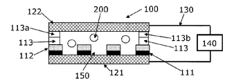
- FIG. 1 It is the figure (exploded view) which showed an example of the cell holding means (board
- FIG. 1 It is a front view of the cell holding means (substrate) shown in FIG.
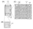
- FIG. 1 It is the figure which showed the preferable aspect of the cell holding means shown in FIG. (A) is a plan view, (B) is an enlarged view of position detection units (square marks) provided at the four corners of the cell holding means, and (C) is an enlarged view of a partial region of (A). is there.
- FIG. 2 is a detailed view of the cell holding means prepared in Example 1.
- (A) is a plan view
- (B) is an enlarged view of position detection units (square marks) provided at the four corners of the cell holding means.
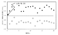
- FIG. 6 is a diagram showing the results of Example 2.
- Black diamonds indicate the results of model cancer cells (PC9 cells), and white circles indicate the results of leukocytes.
- Black diamonds show the results for PC9 cells, black triangles show the results for PC14 cells, black circles show the results for SBC3 cells, and white circles show the results for leukocytes.
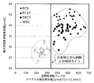
- Example 5 It is the figure which showed the model cancer cell (PC9 cell, PC14 cell, and SBC3 cell) and the spatial frequency distribution spectrum of leukocytes. A region (low frequency region) used for calculation of the spectral intensity integral value in Example 5 is indicated by a dotted line region. It is the figure which showed the result of Example 5. Black diamonds show the results for PC9 cells, black triangles show the results for PC14 cells, black circles show the results for SBC3 cells, and white circles show the results for leukocytes. It is the figure which showed the result of Example 6.
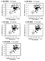
- D) is the result when the integration range is 5 to 14 pixels (the integration range is 9 pixels) when 13 pixels (the integration range is 8 pixels).
- the black diamonds show the results for PC9 cells, the black triangles show the results for PC14 cells, the black circles show the results for SBC3 cells, and the white circles show the results for leukocytes. It is the figure which showed the result of Example 7. It is a schematic diagram for demonstrating discrimination
- FIG. 1 shows an example of a substrate having a holding part for holding cells, which is provided in a preferred embodiment of the present invention.
- 2 is a front view of the substrate shown in FIG.
- a flat light shielding member 111 having a through hole 111a, a flat insulator 112 having a through hole 112a, and a flat spacer 113 having an introduction port 113a, a discharge port 113b, and a through portion 113c.
- the through-hole 111a included in the light-shielding member 111 and the through-hole 112a included in the insulator 112 have the same size and shape, and the light-shielding member 111 and the insulator 112 are provided so that the positions of the respective through-holes coincide with each other.
- the holding part 150 is configured by the electrode 121 provided in close contact with the lower part of the through-hole 111a, the through-hole 112a, and the light shielding member 111. When a liquid containing cells is introduced from the introduction port 113a, the cell is transferred to the holding part 150 through the through-hole 113c. Is introduced.
- the electrode 122 is provided in close contact with the upper portion of the spacer 113 to prevent scattering and evaporation of the liquid containing cells introduced from the introduction port 113a. Note that the electrode 122 has a structure that can be detached from the spacer 113 in order to facilitate the collection of the cells held in the holding unit 150.
- FIG. 3 shows a preferred embodiment of the cell holding means 114 including the electrode 121, the light shielding member 111, and the insulator 112 in the substrate 100 shown in FIG.
- a position detection unit (square mark) 115 for detecting and correcting a positional shift of the cell holding unit 114 is provided around the cell holding unit 114 shown in FIG. 3 (four corners), and a position where the light shielding member 111 and the insulator 112 are provided.
- position detection units square mark 116 and cross mark 117 for detecting and correcting the position of the cell acquired by the detecting means are provided (FIG. 3).
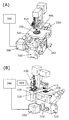
- FIG. 1 An example of the cell recovery apparatus of the present invention is shown in FIG. 1
- FIG. A base 310 as a base of the device; A substrate 100 according to FIGS. 1 and 2; A substrate moving unit 320 for moving the substrate 100 and a collection tube 500 to be described later in the XY-axis direction (horizontal direction); An irradiation unit 330 for irradiating the cells held by the holding unit provided on the substrate 100 with light; A detection unit (objective lens) 340 for acquiring optical information derived from the cells obtained by irradiating light to the cells held in the holding unit by the irradiation unit 330 and the cell-derived based on the optical information An image capturing unit (image acquisition camera) 350 for capturing an image; An analysis unit 360 for performing a two-dimensional Fourier transform on the cell-derived image captured by the image capturing unit 350 and analyzing the cell based on the spatial frequency distribution of the image after the conversion; A nozzle 410 and a suction / discharge pump 420, which are provided on the base 310 and are held by a holding unit provided on the substrate 100 and
- substrate 100 is optically detected by the detection part 340, the image capture part 350, and the analysis part 360, it is necessary to form at least the said holding part with a translucent material. is there.
- the tip of the nozzle 410 is preferably removable so as to prevent contamination from the measurement sample.
- FIGS. 1 to 4 Next, an example of a cell detection method and a cell recovery method using the cell recovery apparatus of the present invention shown in FIGS. 1 to 4 will be described with reference to FIGS.
- Step of introducing cells into the holding unit A liquid containing the cells 200 is introduced from the introduction port 113a provided in the substrate 100 shown in FIG. 1, and the cells 200 are introduced into the holding unit 150 using the dielectrophoretic force 600. . Specifically, a dielectrophoretic force 600 is generated by applying an alternating voltage from the signal generator 140 to the electrodes 121 and 122, and the cell 200 is introduced into the holding unit 150.
- the liquid containing cells to be introduced into the substrate 100 shown in FIG. 1 may be a liquid suspended so that the cells can move by dielectrophoretic force.
- an aqueous solution containing saccharides such as mannitol, glucose, sucrose
- examples include a liquid in which a sample containing cells is suspended in an aqueous solution further containing an electrolyte such as calcium chloride and magnesium chloride and / or a protein such as BSA (bovine serum albumin).
- an electrolyte such as calcium chloride and magnesium chloride and / or a protein such as BSA (bovine serum albumin).
- BSA bovine serum albumin
- the concentration of mannitol to be added may be a concentration that makes an isotonic solution, specifically, between 250 mM and 350 mM.
- the AC voltage applied from the signal generator 140 to the electrodes 121 and 122 is preferably an AC voltage having a waveform in which charging / discharging of the cells 200 held in the holding unit 150 is periodically repeated, and the frequency is from 100 kHz to 3 MHz. It is particularly preferable that the electric field strength is between 1 ⁇ 10 5 and 5 ⁇ 10 5 V / m (see WO 2011/149032 and JP 2012-013549 A).
- Step of adding reagent containing adhesive substance 700 By introducing a reagent containing adhesive substance 700 from the inlet 113a provided in the substrate 100 shown in FIG.
- the holding unit 150 and the cell 200 introduced into the holding unit are bonded via the substance 700.
- the modification of the holding unit 150 with the adhesive substance 700 may be performed before the step (1).
- the adhesive substance is not particularly limited as long as it can specifically bind to cells.
- a biocompatible anchorfor that has a lipid oleyl group that binds to a lipid bilayer membrane of a cell (ligand-receptor, sugar chain-lectin, antigen-antibody) that can specifically bind to a substance on the cell surface.
- Membrane (BAM) ligand-receptor, sugar chain-lectin, antigen-antibody
- BAM Membrane
- poly-L-lysine is preferable because it can electrostatically bind to the cell surface in a relatively short time.
- the concentration is preferably 0.01 (w / v)% or less.
- this step is preferably completed in a short time in order to reduce damage to cells.
- the reagent containing the adhesive substance 700 may contain saccharide (for example, 250 mM to 350 mM mannitol) having the same concentration as the liquid containing the cells 200 introduced in (1). .
- Step of capturing an image derived from the cell 200 After the reagent including the adhesive substance 700 is discharged from the discharge port 113b, the substrate moving unit 320 moves the substrate in the XY axis direction, and the irradiation unit 330, the detection unit 340, and the image
- the capturing unit 350 acquires the image (bright field image) derived from the cell 200 and the position information of the cell 200 held in the holding unit 150. Note that a plurality of images (bright field images) derived from the cells 200 are acquired for each of the cells held in the holding unit 150.
- Step of converting the captured image (not shown) A single cell image region is recognized from a plurality of images derived from the cells 200 held in the holding unit 150 and acquired in the step (3), a region of interest (ROI) is set, and then a two-dimensional FFT (fast Fourier transform) is performed. ) Process to obtain a spatial frequency distribution image. In the obtained image, the target cell is detected based on at least one of the spatial frequency distribution in the low frequency region or the maximum value of the spatial frequency distribution.
- ROI region of interest
- FFT fast Fourier transform
- Step (5) Step of recovering target cell 210
- the electrode 122 is removed from the spacer 113 and then sucked by the nozzle 410, so that the target cell 210 is recovered from the substrate 100. Cells 210 are collected.
- the aspiration of the target cell 210 is performed by moving the holding unit holding the target cell 210 detected in the step (4) to the center of the nozzle 410 using the substrate moving unit 320 and the nozzle moving unit 430,
- the target cells 210 are collected by aspirating the liquid.
- a displacement of several tens to several hundreds of ⁇ m occurs between the substrate (cell holding means) and the center of the optical axis of the detection unit 340.
- the positions of at least three points are respectively calculated. Based on the calculated result, the deviation generated in the process of removing from the spacer 113 is calculated using the Helmat transform equation.
- the physical address of the substrate moving unit 320 is corrected and recognized as an accurate position of the substrate (cell holding means).
- the substrate moving unit 320 may move the nozzle 410 to the position of the target cell 210 converted to the corrected position of the holding means 110 by adjusting the nozzle 410 to the center of the optical axis of the detecting unit 340 in advance.
- the suction position of the target cell 210 by the nozzle 410 is a position shifted by a certain distance in the horizontal direction from the center of the holding unit 150 where the target cell 210 is sampled, because the target cell 210 can be sucked easily.
- the suction position of the target cell 210 is set to the length of 0.1 to 2 times the diameter of the holding unit 150 in the horizontal direction from the center of the holding unit 150 (however, the distance between adjacent holding units 150 is 2). It is preferable that the position is shifted from the height of the holding part 150 and is higher by 0.01 to 2 times the height of the holding part 150 in the vertical direction. Further, before the target cell 210 is sucked by the nozzle 410, an operation of adding a solution containing an enzyme that weakens the adhesion between the target cell 210 and the holding unit 150 may be performed.
- the substrate moving unit 320 determines the center position of the tip of the nozzle 410 from the position information of the holding unit. After the substrate 100 is moved so as to match the center of the holding unit 150 (or a position shifted by a certain distance in the horizontal direction from the center of the holding unit), the nozzle moving unit 430 holds the vertical position of the tip of the nozzle 410. It is carried out by moving from the height of the portion 150 to a position that is higher by a certain height in the vertical direction (for example, a position that is higher by 0.01 to 2 times the height of the holding portion 150).
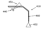
- the nozzle 410 provided in the cell collection device of this aspect is provided with a nozzle irradiation unit 440 at the base, and when irradiated with light 451 from the nozzle irradiation unit 440, it passes through the nozzle light guide unit 460, Light 452 is irradiated from the tip of the nozzle 410 to the substrate.
- the tip of the nozzle 410 can be acquired as a clear ring-shaped image by the detection unit 340 and the measurement unit, so that the position of the tip of the nozzle 410 can be accurately calculated, and the target cell 210 is retained. It is easy to calculate the deviation from the holding unit 150.
- the vertical position of the tip of the nozzle 410 also irradiates light from the tip of the nozzle 410 to the substrate by the nozzle shown in FIG. 7, and the contrast or image differential value of the image obtained by the detection unit 340 and the image capturing unit 350 is also shown.
- the nozzle (FIG. 7) provided in the cell recovery device of this embodiment is bent at two locations from the root to the tip, and the direction of the light 451 emitted from the nozzle root directly irradiates the substrate and the detection unit 340. This is a preferable mode of the nozzle 410 because it is in a direction that does not.
- a method of sucking the target cell 210 with the nozzle 410 a method of sucking with negative pressure using the pump 420 is adopted. Since the target cell 210 is relatively strongly adhered to the holding unit 150, when a syringe pump is used as a pump, it is necessary to suck at a high flow rate, and specifically, a flow rate of 0.01 ⁇ L / s or more is required. is there. However, if the flow rate is increased too much, bubbles are generated in the flow path and the flow rate is significantly reduced. Therefore, the flow rate is preferably between 0.01 and 5.0 ⁇ L / s.
- the inner diameter of the nozzle 410 is preferably larger than the diameter of the cells to be sucked in order to prevent clogging of the nozzle 410 after the suction.
- the inner diameter of the nozzle 410 may be set between 25 ⁇ m and 35 ⁇ m.
- Step of discharging the collected target cells 210 to the collection tube 500 The target cells 210 collected by suction by the nozzle 410 are discharged to the collection tube 500. The target cells 210 collected in the collection tube 500 are then subjected to further analysis such as gene analysis.
- the target cell is detected and recovered based only on the bright field image derived from the cell.
- the target cell is detected and recovered based on the cell-derived bright field image and fluorescent image or
- a step of permeating cells through the membrane, a step of adding a blocking agent for preventing the generation of non-specific labels, And a step of adding a fluorescent labeling reagent may be added (Japanese Patent Application No. 2015-018410).
- Example 1 Creation of Cell Holding Unit The cell holding unit 114 in which the light shielding member 111, the insulator 112, and the electrode 121 shown in FIG. 1 and FIG. (1) A Cr film having a thickness of 200 nm was formed on a blue plate glass substrate having a thickness of 1.2 mm on which an ITO conductive film was formed. (2) A resist agent was applied by a spin coater, and the areas where the fine holes 111a, the position detection parts (square marks) 115 and 116, and the position detection parts (cross marks) 117 were formed were masked. Note that the position detection unit 115 has a finer rectangular shape formed therein as shown in FIG.
- the focal position of an objective lens is determined by determining the change in the differential value of the image captured when the microscope objective lens is moved up and down, and determining the position of the objective lens with the maximum differential value as the most focused position. To do.
- the focus position can be easily and accurately specified in a wide range of image areas.
- FIG. (3) A pattern was formed by exposing to a UV light source and etching (developer: 4% phosphate) to remove the Cr film in the masked region and then baking. (4) After removing the resist, SU-8 manufactured by Microchem Co., Ltd.
- the cell holding means 114 shown in FIG. 3 was produced by exposure with a UV light source and a development process (developer: propylene glycol monomethyl ether acetate) and a baking process.
- a UV light source and a development process (developer: propylene glycol monomethyl ether acetate) and a baking process.
- developer propylene glycol monomethyl ether acetate
- the position detection unit can be detected by fluorescence detection by the detection unit.
- the cell holding means 114 actually produced by the above method is shown in FIG.
- the four position detectors 115a, 115b, 115c, and 115d have a rectangular shape with a side of 500 ⁇ m (FIG. 8B), and among these, the position detector 115a is set as the coordinate origin (0 mm, 0 mm).
- the positions of the other position detectors are (55 mm, 0 mm) for the position detector 115 b, (55 mm, 28 mm) for the position detector 115 c, and (0 mm, 28 mm) for the position detector 115 d (FIG. 8 ( A)).
- Example 2 Detection of Cancer Cells Based on Maximum Value of Spatial Frequency Distribution
- the substrate 100 shown in FIG. 1 was produced by combining the spacer 113 and the electrode 122 with the cell holding means 114 (FIG. 8) produced in Example 1.
- a solution containing PC9 cells (pulmonary differentiated adenocarcinoma cells) as white blood cells and model cancer cells is introduced from the inlet 113a provided in the produced substrate 100, and an alternating voltage (voltage 20 Vpp, frequency 1 MHz, rectangular wave) is applied. By applying, the cells were held in the holding part (pore diameter ⁇ 30 ⁇ m, depth 40 ⁇ m) by the dielectrophoretic force.
- Cell staining solution fluorescein isothiocyanate (FITC) -labeled anti-cytokeratin (CK) antibody, R-phycoerythrin (PE) -labeled anti-HER2 antibody, allophycocyanin (APC) -labeled anti-CD45 antibody, DAPI
- FITC fluorescein isothiocyanate
- PE R-phycoerythrin
- APC allophycocyanin
- DAPI Cell staining solution from the inlet 113a (Solution containing 0.5 ⁇ g / mL of 4 ′, 6-diamidino-2-phenyllinole) 800 ⁇ L each and reacting at 25 ° C. for 30 minutes, cell labeling, and then introducing an aqueous mannitol solution from the inlet 113a Washed with.
- DAPI-positive and CK-positive cells were detected as PC9 cells, and DAPI-positive and CD45-positive cells were detected as leukocytes.
- FIG. 11 shows the result of calculating the maximum value of the spatial frequency distribution for each of white blood cells (20 samples) and model cancer (PC9) cells (20 samples).
- the maximum value of the spatial frequency distribution is shown on the vertical axis as the pixel value of the diameter in the spatial frequency distribution image after the two-dimensional FFT processing. From FIG. 11, for example, by setting 35 pixels in diameter (17.5 pixels in radius) (wavelength: 2.314 ⁇ m, spatial frequency: 0.4321 ⁇ m ⁇ 1) as a threshold value of the maximum value of the spatial frequency distribution, PC9 cells are leukocytes. It can be seen that it can be detected separately.
- Example 3 Detection of Cancer Cells Based on Maximum Value of Spatial Frequency Distribution
- Part 2 a solution containing PC9 cells, PC14 cells (pulmonary poorly differentiated adenocarcinoma) and SBC3 cells (small lung cell carcinoma cells) as leukocytes and model cancer cells Detected model cancer cells in the same manner as in Example 2.
- the results are shown in FIG.
- the PC14 cell for example, has a threshold value of 35 pixels (wavelength of the maximum value of the spatial frequency distribution (diameter of the spatial frequency distribution image after the two-dimensional FFT processing), as in the PC9 cell (Example 2).
- SBC3 cells had specimens that partially overlapped with the maximum value of the spatial frequency distribution in white blood cells, and could not be clearly distinguished from white blood cells only by the maximum value of the spatial frequency distribution.
- Example 4 Detection of Cancer Cells Based on Maximum Value of Spatial Frequency Distribution
- cancer cells were detected based on the maximum value of the spatial frequency distribution when the threshold value of the spectral intensity (binarization) of the spatial frequency was set to 15.
- Table 1 The results are shown in Table 1.
- the numbers in Table 1 represent the positive detection rate (%) of each cell at the threshold value of the maximum value of the set spatial frequency distribution.
- conditions that can be detected at a detection rate of 70% or more for model cancer cells and 20% or less for false positives for leukocytes are indicated by areas with black background and white characters.
- the threshold value for binarization 10
- the threshold value of the maximum value of the spatial frequency distribution is from 40 pixels to 41 pixels (wavelength: 1.976 to 2.025 ⁇ m).
- the threshold value for binarization is 11
- the threshold value of the maximum value of the spatial frequency distribution is binary between 38 pixels and 41 pixels (wavelength: 1.976 to 2.132 ⁇ m).
- the threshold value for binarization is 12
- the threshold value for the maximum value of the spatial frequency distribution is between 35 pixels and 39 pixels (wavelength: 2.077 to 2.314 ⁇ m).
- the threshold value of the maximum value of the spatial frequency distribution is between 32 pixels and 38 pixels (wavelength: 2.132 to 2.531 ⁇ m), and the binarization threshold value is 14.
- the threshold value for binarization is set to 15 between 31 and 37 pixels (wavelength: 2,189 to 2.613 ⁇ m)
- the threshold value for the maximum value of the spatial frequency distribution is 29.
- each pixel is set between 36 pixels (wavelength: 2.25 to 2.793 ⁇ m), it can be detected with a model cancer cell detection rate of 70% or more and a leukocyte false positive of 20% or less. If the threshold value for binarization is 12, the threshold value for the maximum value of the spatial frequency distribution is between 35 and 37 pixels (wavelength: 2.189 to 2.314 ⁇ m).
- the threshold value of the maximum value of the spatial frequency distribution is between 34 pixels and 35 pixels (wavelength: 2.314 to 2.382 ⁇ m)
- the binarization threshold value is 14
- the threshold value of spatial frequency distribution is between 31 pixels and 35 pixels (wavelength: 2.314 to 2.613 ⁇ m)
- the threshold value of binarization is 15 If the threshold value of the maximum value of the frequency distribution is set between 30 and 34 pixels (wavelength: 2.382 to 2.70 ⁇ m), the detection rate of model cancer cells is 80% or more and the false positive of leukocytes Inspection at 10% or less It can be. In this example, no conditions were found that could detect all model cancer cells separately from leukocytes.
- Example 5 Detection of Cancer Cells Based on Spatial Frequency Distribution in Low Frequency Region (Part 1) It was found from Examples 3 and 4 that the method based on the maximum value of the spatial frequency distribution might cause false positives (or false negatives) in some model cancer cells (FIG. 12 and Table 1). Therefore, we tried to detect model cancer cells based on spatial frequency distribution from another viewpoint.
- Example 2 (6) Of the spatial frequency distribution image of each cell (PC9 cell, PC14 cell, SBC3 cell or leukocyte) obtained in Example 2 (6), 5 pixels (wavelength from the center of the spatial frequency distribution image, specifically the spatial frequency distribution image. : 8.1 ⁇ m) to 11 pixels (wavelength: 3.68 ⁇ m) (the dotted line region in FIG. 13), the integral value of the spectral intensity was calculated. The results are shown in FIG. By setting the threshold value of the integral value of the spectral intensity to 340, any model cancer cells (PC9 cells, PC14 cells, and SBC3 cells) could be detected separately from leukocytes.
- any model cancer cells PC9 cells, PC14 cells, and SBC3 cells
- Example 6 Detection of Cancer Cells Based on Spatial Frequency Distribution in Low Frequency Region (Part 2) From Example 5, it was found that the model cancer cells can be detected separately from the white blood cells by using the integral value of the spectrum intensity in the region from 5 pixels to 11 pixels from the center of the spatial frequency distribution image. It was verified whether the same detection could be performed even if the calculation range of the value was changed.
- the spectral intensity integrated value (horizontal axis) of the spatial frequency is the largest among the 80 target cells (20 PC9 cells, PC14 cells, SBC3 cells, and white blood cells). It is expressed as a relative value when the integrated value of the cells is 1.
- the model cancer cells can be detected separately from the leukocytes (FIGS. 15 (d) and 15 (e) and FIG. 16).
- Example 7 Detection of Cancer Cells Based on Spatial Frequency Distribution in Low Frequency Region (Part 3)
- the integration range is 1 pixel (range from 5 pixels to 6 pixels) to 9 pixels (range from 5 pixels to 14 pixels)
- the integrated value of the spectrum intensity of the model cancer cells and leukocytes is calculated.
- the integration range is 15 pixels (range from 5 pixels to 20 pixels), 25 pixels (range from 5 pixels to 30 pixels), 35 pixels (range from 5 pixels to 40 pixels), 45 pixels ( The range was expanded from 5 pixels to 50 pixels) and 65 pixels (range from 5 pixels to 70 pixels).
- FIG. 17 is a diagram in which the difference from the relative value of the white blood cell having the maximum intensity integral value is plotted.
- FIG. 17 also plots the results of Example 6. From FIG. 17, when the integration range is between 4 pixels and 45 pixels, the difference between the relative value of the model cancer cell with the smallest spectral intensity integral value and the relative value of the white blood cell with the largest spectral intensity integral value is 0 or more. It can be seen that model cancer cells can be detected separately from leukocytes. In addition, when the integration range is between 5 pixels and 15 pixels, it can be seen that the model cancer cells can be detected separately from the white blood cells.
Landscapes
- Chemical & Material Sciences (AREA)
- Life Sciences & Earth Sciences (AREA)
- Engineering & Computer Science (AREA)
- Health & Medical Sciences (AREA)
- Bioinformatics & Cheminformatics (AREA)
- Wood Science & Technology (AREA)
- Biotechnology (AREA)
- Organic Chemistry (AREA)
- Zoology (AREA)
- Biochemistry (AREA)
- General Health & Medical Sciences (AREA)
- Biomedical Technology (AREA)
- Medicinal Chemistry (AREA)
- Sustainable Development (AREA)
- Analytical Chemistry (AREA)
- Genetics & Genomics (AREA)
- General Physics & Mathematics (AREA)
- Physics & Mathematics (AREA)
- General Engineering & Computer Science (AREA)
- Microbiology (AREA)
- Immunology (AREA)
- Hematology (AREA)
- Food Science & Technology (AREA)
- Pathology (AREA)
- Urology & Nephrology (AREA)
- Molecular Biology (AREA)
- Theoretical Computer Science (AREA)
- Investigating Or Analysing Biological Materials (AREA)
- Apparatus Associated With Microorganisms And Enzymes (AREA)
- Investigating, Analyzing Materials By Fluorescence Or Luminescence (AREA)
Abstract
体液、組織分散液、細胞培養液などの液体試料中に含まれる目的細胞を、前記目的細胞由来の画像を用いて迅速かつ正確に検出できる装置、および検出した前記目的細胞を精度よく回収可能な装置を提供すること。 細胞に光を照射する細胞照射手段と、細胞照射手段で照射して得られる前記細胞由来の画像を取り込む画像取り込み手段と、画像取り込み手段で取り込まれた前記画像に対して2次元フーリエ変換を行なう画像変換手段と、画像変換手段で変換された画像の低周波数領域における空間周波数分布または画像変換手段で変換された画像の空間周波数分布の最大値のうち少なくともいずれか一つに基づき目的細胞を検出する画像検出手段と、を備えた細胞検出装置、および前記画像検出手段で検出した前記目的細胞をノズルによる吸引吐出により回収する回収手段とをさらに備えた細胞回収装置により、前記課題を解決する。
Description
本発明は、体液、組織分散液、細胞培養液などの液体試料中に含まれる目的細胞を検出する装置、および前記検出した目的細胞を回収する装置に関する。特に本発明は、目的細胞の検出を、細胞由来の画像を用いて行なう装置に関する。
溶液中に同じ種類の細胞が含まれていたとしても、当該細胞の性質が個々に異なることが知られている(非特許文献1)。一方で、溶液中に含まれる細胞から通常得られる情報は、個々の細胞の情報が平均化された情報となるため、個々の細胞の情報を得ることは難しい。そのため、溶液中に含まれる細胞を個別に解析し、個々の細胞の情報を得ることへの関心が高まっている。
溶液中に含まれる細胞を個別に解析する例として、血中循環腫瘍細胞(Circulating Tumor Cells、以下CTC)の解析があげられる。CTCは癌の転移や再発に重要な役割を果たすと考えられており、CTCの解析が可能になると、癌患者の術後診断や投薬方針を決定することができるため、治療の最適化や効率化につながると考えられる。しかしながら、CTCは未解明な点が多く、またCTCが有する遺伝子の変異やコピー数変化が個々の細胞で異なるという報告もあるため、個別に細胞を解析する必要がある(非特許文献2)。
血液試料中に含まれるCTCの検出方法として、従来より、抗EpCAM(Epithelial Cell Adhesion Molecule)抗体を修飾した磁気微粒子を用いてCTCを濃縮し、CTCを含む細胞を蛍光免疫染色により標識後、前記標識由来の蛍光を検出することで、CTCを正常細胞(白血球)から区別して検出する方法が知られており(非特許文献3)、前記方法を用いたCTC検出装置も商品化されている(CellSearch、ヤンセン・ダイアグノスティックス社製)。しかしながら、近年、抗EpCAM抗体と反応しないCTCも存在することが知られるようになり、本方法では血液試料中に含まれるCTCを取りこぼすおそれがあることがわかってきた。そのため、EpCAMなどのマーカーを用いずにCTCを検出可能な装置が求められている。
マーカーを用いずに目的細胞の検出が可能な装置として、細胞由来の画像を用いて光学的に目的細胞を検出する装置が知られている(特許文献1および2)。特許文献1は、細胞を撮影して得られる画像からサイズ、外形、核の形状などの特徴を抽出するための特徴抽出手段と、抽出された前記特徴から前記細胞の良否を判定する良否判定手段と、前記特徴抽出手段および前記良否判定手段の組み合わせを解析レシピとして記憶する解析レシピ記憶手段と、前記解析レシピ記憶手段から目的細胞に対応したレシピを選択し当該レシピに基づき前記特徴抽出手段および前記良否判定手段を駆動させることで目的細胞の良否を判断する解析手段とを備えた、細胞の良否を判定する装置を開示している。特許文献2は、フローセル中を流れる血液に対して光を照射することで得られた、血液中に含まれる細胞由来の画像に対し、光学的に2次元フーリエ変換を行なった後、空間光フィルタによりフーリエ変換後の像の光軸を中心とする一定範囲の部分を選択的に通過させ、前記通過した部分に対しさらに光学的に2次元フーリエ変換を行なうことで血液中に含まれる癌細胞を検出する装置を開示している。
Groria,H.H.,Cancer Research,44,2259-2265(1984)
Martina,A.,et al.,Oncotarget,4,812-813(2013)
Riethdorf,S.,et. al.,Clincal Cancer Research,13(3),920-928(2007)
本発明の課題は、体液、組織分散液、細胞培養液などの液体試料中に含まれる目的細胞を、前記目的細胞由来の画像を用いて検出する装置であって、前記目的細胞の検出を迅速かつ正確に検出可能な装置を提供することにある。また本発明の別の課題は、体液、組織分散液、細胞培養液などの液体試料中に含まれる目的細胞を、前記目的細胞由来の画像を用いて検出し、当該検出した目的細胞を回収する装置であって、前記目的細胞を精度よく回収可能な装置を提供することにある。
上記課題を解決するために、本発明者らは鋭意検討を重ねた結果、本発明に到達した。
すなわち本発明の第一の態様は、
細胞に光を照射する細胞照射手段と、細胞照射手段で照射して得られる前記細胞由来の画像を取り込む画像取り込み手段と、画像取り込み手段で取り込まれた前記画像に対して2次元フーリエ変換を行なう画像変換手段と、画像変換手段で変換された画像の空間周波数分布に基づき目的細胞を検出する画像検出手段と、を備えた細胞検出装置であって、
前記画像検出手段による目的細胞の検出を、画像変換手段で変換された画像の低周波数領域における空間周波数分布または画像変換手段で変換された画像の空間周波数分布の最大値のうち少なくともいずれか一つに基づき行なう、前記装置である。
細胞に光を照射する細胞照射手段と、細胞照射手段で照射して得られる前記細胞由来の画像を取り込む画像取り込み手段と、画像取り込み手段で取り込まれた前記画像に対して2次元フーリエ変換を行なう画像変換手段と、画像変換手段で変換された画像の空間周波数分布に基づき目的細胞を検出する画像検出手段と、を備えた細胞検出装置であって、
前記画像検出手段による目的細胞の検出を、画像変換手段で変換された画像の低周波数領域における空間周波数分布または画像変換手段で変換された画像の空間周波数分布の最大値のうち少なくともいずれか一つに基づき行なう、前記装置である。
また本発明の第二の態様は、
細胞に光を照射する細胞照射手段と、細胞照射手段で照射して得られる前記細胞由来の画像を取り込む画像取り込み手段と、画像取り込み手段で取り込まれた前記画像に対して2次元フーリエ変換を行なう画像変換手段と、画像変換手段で変換された画像の空間周波数分布に基づき細胞を検出する画像検出手段と、を備えた細胞検出装置であって、
前記装置に、画像取り込み手段で取り込まれた前記画像の蛍光または発光を検出する光検出手段をさらに備え、かつ目的細胞の検出を、画像検出手段における画像変換手段で変換された画像の低周波数領域における空間周波数分布または画像変換手段で変換された画像の空間周波数分布の最大値のうち少なくともいずれか一つに基づく検出結果、および光検出手段における蛍光検出または発光検出結果に基づき行なう、前記装置である。
細胞に光を照射する細胞照射手段と、細胞照射手段で照射して得られる前記細胞由来の画像を取り込む画像取り込み手段と、画像取り込み手段で取り込まれた前記画像に対して2次元フーリエ変換を行なう画像変換手段と、画像変換手段で変換された画像の空間周波数分布に基づき細胞を検出する画像検出手段と、を備えた細胞検出装置であって、
前記装置に、画像取り込み手段で取り込まれた前記画像の蛍光または発光を検出する光検出手段をさらに備え、かつ目的細胞の検出を、画像検出手段における画像変換手段で変換された画像の低周波数領域における空間周波数分布または画像変換手段で変換された画像の空間周波数分布の最大値のうち少なくともいずれか一つに基づく検出結果、および光検出手段における蛍光検出または発光検出結果に基づき行なう、前記装置である。
さらに本発明の第三の態様は、
細胞に光を照射する細胞照射手段と、細胞照射手段で照射して得られる前記細胞由来の画像を取り込む画像取り込み手段と、画像取り込み手段で取り込まれた前記画像に対して2次元フーリエ変換を行なう画像変換手段と、画像変換手段で変換された画像の空間周波数分布に基づき目的細胞を検出する画像検出手段と、画像検出手段で検出した前記目的細胞をノズルによる吸引吐出により回収する回収手段と、を備えた細胞回収装置であって、
前記画像検出手段による目的細胞の検出を、画像変換手段で変換された画像の低周波数領域における空間周波数分布または画像変換手段で変換された画像の空間周波数分布の最大値のうち少なくともいずれか一つに基づき行なう、前記装置である。
細胞に光を照射する細胞照射手段と、細胞照射手段で照射して得られる前記細胞由来の画像を取り込む画像取り込み手段と、画像取り込み手段で取り込まれた前記画像に対して2次元フーリエ変換を行なう画像変換手段と、画像変換手段で変換された画像の空間周波数分布に基づき目的細胞を検出する画像検出手段と、画像検出手段で検出した前記目的細胞をノズルによる吸引吐出により回収する回収手段と、を備えた細胞回収装置であって、
前記画像検出手段による目的細胞の検出を、画像変換手段で変換された画像の低周波数領域における空間周波数分布または画像変換手段で変換された画像の空間周波数分布の最大値のうち少なくともいずれか一つに基づき行なう、前記装置である。
また本発明の第四の態様は、
細胞に光を照射する細胞照射手段と、細胞照射手段で照射して得られる前記細胞由来の画像を取り込む画像取り込み手段と、画像取り込み手段で取り込まれた前記画像に対して2次元フーリエ変換を行なう画像変換手段と、画像変換手段で変換された画像の空間周波数分布に基づき細胞を検出する画像検出手段と、ノズルによる吸引吐出により細胞を回収する回収手段と、を備えた細胞回収装置であって、
前記装置に、画像取り込み手段で取り込まれた前記画像の蛍光または発光を検出する光検出手段をさらに備え、かつ回収手段で回収する目的細胞の検出を、画像検出手段における画像変換手段で変換された画像の低周波数領域における空間周波数分布または画像変換手段で変換された画像の空間周波数分布の最大値のうち少なくともいずれか一つに基づく検出結果、および光検出手段における蛍光検出または発光検出結果に基づき行なう、前記装置である。
細胞に光を照射する細胞照射手段と、細胞照射手段で照射して得られる前記細胞由来の画像を取り込む画像取り込み手段と、画像取り込み手段で取り込まれた前記画像に対して2次元フーリエ変換を行なう画像変換手段と、画像変換手段で変換された画像の空間周波数分布に基づき細胞を検出する画像検出手段と、ノズルによる吸引吐出により細胞を回収する回収手段と、を備えた細胞回収装置であって、
前記装置に、画像取り込み手段で取り込まれた前記画像の蛍光または発光を検出する光検出手段をさらに備え、かつ回収手段で回収する目的細胞の検出を、画像検出手段における画像変換手段で変換された画像の低周波数領域における空間周波数分布または画像変換手段で変換された画像の空間周波数分布の最大値のうち少なくともいずれか一つに基づく検出結果、および光検出手段における蛍光検出または発光検出結果に基づき行なう、前記装置である。
また本発明の第五の態様は、回収手段における前記ノズルの先端部が透光性材料で形成されており、かつ前記ノズルに光を照射するためのノズル照射部およびノズル照射部で照射した光を前記ノズルの先端部に導くためのノズル導光部を前記回収手段にさらに設けた、前記第三または第四の態様に記載の装置である。
また本発明の第六の態様は、画像検出手段による細胞の検出を、画像変換手段で変換された画像の低周波数領域における空間周波数分布および画像変換手段で変換された画像の空間周波数分布の最大値に基づき行なう、前記第一から第五の態様のいずれかに記載の装置である。
また本発明の第七の態様は、細胞を保持する保持部を有した細胞保持手段をさらに備え、かつ細胞照射手段が前記保持部に保持された細胞に光を照射する、前記第一から第六の態様のいずれかに記載の装置である。
また本発明の第八の態様は、細胞照射手段から照射される光により蛍光を発する位置検出部を細胞保持手段にさらに設けた、前記第七の態様に記載の装置である。
以下、本発明を詳細に説明する。
本発明の装置で検出および回収する細胞に特に限定はなく、リンパ球、赤血球、白血球、血小板、腫瘍細胞が例示できる。特に本発明の装置は、血液中に含まれる腫瘍細胞(CTC)および白血球の検出ならびに回収に有用な装置である。
本発明の装置に備える細胞照射手段において、細胞に光を照射する光源に特に限定はなく、電球、ハロゲンランプ、水銀ランプ、メタルハライドランプ、半導体レーザー、ガスレーザー、LEDなどを用いることができる。また必要に応じ、光源からの光を、光学フィルター、ミラーおよびレンズなどから構成される光学系を経由して、細胞に照射してもよい。なお本発明の装置が、細胞を保持する保持部を有した細胞保持手段をさらに備えている場合、細胞照射手段は前記保持部に保持された細胞に光が照射されるよう、光源および光学系を設ければよい。
本発明の装置に備える細胞照射手段において、細胞に光を照射する光源に特に限定はなく、電球、ハロゲンランプ、水銀ランプ、メタルハライドランプ、半導体レーザー、ガスレーザー、LEDなどを用いることができる。また必要に応じ、光源からの光を、光学フィルター、ミラーおよびレンズなどから構成される光学系を経由して、細胞に照射してもよい。なお本発明の装置が、細胞を保持する保持部を有した細胞保持手段をさらに備えている場合、細胞照射手段は前記保持部に保持された細胞に光が照射されるよう、光源および光学系を設ければよい。
本発明の装置に備える画像取り込み手段は、前述した細胞照射部で細胞を照射して得られる当該細胞由来の画像を取り込む手段である。取り込む画像の一例として、広い波長領域での透過光または反射光による光強度分布や、位相差から合成される光強度分布から構成される像(明視野像)があげられる。画像取り込み手段で取り込む明視野像は、細胞形態に関する情報が取得可能であれば、特に制限されない。細胞形態に関する情報の一例として、細胞の直径、面積、体積、周囲長、真円度があげられる。なお細胞があらかじめ免疫染色などによる蛍光標識や発光基質による標識がされている場合、当該標識物質由来の蛍光強度または発光強度の絶対値、または当該標識物質由来の蛍光強度または発光強度のピーク値、最小値、平均値もしくは積分値といった計算値から構成される像(蛍光画像または発光画像)も、画像取り込み手段で取り込む画像に含まれる。
本発明の装置に備える画像変換手段は、前述した画像取り込み手段で取り込まれた細胞由来の画像に対して2次元フーリエ変換を行なう。具体的には、画像取り込み部で取り込んだ細胞由来の画像(明視野像や蛍光画像など)それぞれの関心領域(ROI:Region of Interest)に対し2次元フーリエ変換を行ない、空間周波数分布画像を得る。
本発明の装置に備える画像検出手段は、前述した画像変換手段で変換された画像の空間周波数分布に基づき目的細胞を検出する。細胞種(例えば血液試料の場合、白血球や血中循環腫瘍細胞(CTC)など)により形状や明暗模様が異なるため、空間周波数分布にも違いが生じる。画像検出手段は、この違いに基づき目的細胞を検出する。本発明の装置に備える画像検出手段の一態様は、画像変換手段で変換された画像のうち、低周波数領域(光軸を中心とする内側の一定領域)の空間周波数分布に基づき、目的細胞を検出する。前記検出は例えば、画像変換手段で2次元フーリエ変換された画像のうち、低周波数領域のスペクトル強度の積分値の大きさに基づき、行なえばよい。なお本明細書において低周波数領域とは3ピクセルから50ピクセル(波長:0.81から13.5μm)までの領域のことをいい、5ピクセルから20ピクセル(波長:2.025から8.1μm)までの領域とすると好ましく、5ピクセルから11ピクセル(波長:3.68から8.1μm)までの領域とするとより好ましい。ここで2次元フーリエ変換後の画像の波長(空間周波数)を示すのに「ピクセル」値を用いているが、本明細書において「ピクセル」値とは、20倍の対物レンズおよびCCDカメラ(8ビット輝度分解能1024×1024画素数)を用いて取り込まれた細胞由来の画像(1ピクセル=0.405μm)を、100×100ピクセルの関心領域(ROI)で2次元フーリエ変換を行ない得られた画像の空間周波数を「ピクセル」値として表記している。「ピクセル」値から波長および空間周波数への換算は以下の式を用いればよい。
波長[μm]=取り込んだ画像のROI一辺の距離(0.405[μm/ピクセル]×100[ピクセル])/2次元フーリエ変換後の画像における半径ピクセル値
空間周波数[μm-1]=1/波長[μm]
具体例として、血液試料中に含まれる白血球と癌細胞(CTC)とを区別して検出したい場合、低周波数領域を画像変換手段で2次元フーリエ変換された画像の中心から5ピクセルから11ピクセル(波長:3.68から8.1μm)までの領域とし、スペクトル強度の積分値の判別しきい値を327から364までの間に設定すればよい。なお本明細書に記載のスペクトル強度の積分値は、画像取り込み時に用いるカメラとして8ビット(256段階)の解像度を有したカメラを用い、0(黒)から255(白)までの数値で表現した輝度に基づき得られる値である。従って、画像取り込み時に用いるカメラの解像度(デジタル分解能)が8ビットから異なると、スペクトル強度の積分値も異なる。また低周波数領域(積分範囲)の設定によっても、スペクトル強度の積分値のしきい値は変化する。そのため本例の場合、あらかじめ白血球など血液試料中に含まれる正常細胞由来の画像(明視野像や蛍光画像など)に対して2次元フーリエ変換を行ない得られた画像のスペクトル強度の積分値に基づき、しきい値を設定するとよい。
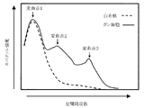
また、特定の低周波数領域を決定するには、空間周波数スペクトルの変曲点により求められた空間周波数対し任意の周波数領域を設定することで決定することが出来る。例えば図18に示すように、白血球に対しガン細胞には異なる特有の変曲点2、3を有している。判別対象(ここでは白血球)と異なる変曲点が複数存在する場合は判別に使用する空間周波数領域を複数に設定しても良い。
空間周波数[μm-1]=1/波長[μm]
具体例として、血液試料中に含まれる白血球と癌細胞(CTC)とを区別して検出したい場合、低周波数領域を画像変換手段で2次元フーリエ変換された画像の中心から5ピクセルから11ピクセル(波長:3.68から8.1μm)までの領域とし、スペクトル強度の積分値の判別しきい値を327から364までの間に設定すればよい。なお本明細書に記載のスペクトル強度の積分値は、画像取り込み時に用いるカメラとして8ビット(256段階)の解像度を有したカメラを用い、0(黒)から255(白)までの数値で表現した輝度に基づき得られる値である。従って、画像取り込み時に用いるカメラの解像度(デジタル分解能)が8ビットから異なると、スペクトル強度の積分値も異なる。また低周波数領域(積分範囲)の設定によっても、スペクトル強度の積分値のしきい値は変化する。そのため本例の場合、あらかじめ白血球など血液試料中に含まれる正常細胞由来の画像(明視野像や蛍光画像など)に対して2次元フーリエ変換を行ない得られた画像のスペクトル強度の積分値に基づき、しきい値を設定するとよい。
また、特定の低周波数領域を決定するには、空間周波数スペクトルの変曲点により求められた空間周波数対し任意の周波数領域を設定することで決定することが出来る。例えば図18に示すように、白血球に対しガン細胞には異なる特有の変曲点2、3を有している。判別対象(ここでは白血球)と異なる変曲点が複数存在する場合は判別に使用する空間周波数領域を複数に設定しても良い。
本発明の装置に備える画像検出手段の別の態様は、画像変換手段で変換された画像のうち、空間周波数分布の最大値(空間周波数分布画像の半径)に基づき、目的細胞を検出する。空間周波数分布の最大値は、例えば、空間周波数のスペクトル強度(輝度)が一定のしきい値以上となる光軸からの距離(半径)の最大値を、空間周波数分布の最大値とすればよい。なお2次元フーリエ変換により得られる画像はピクセル表現となり、粒子検出アルゴリズム等を使用して検出される空間周波数は直径値での表現となるが、空間周波数または波長に換算する場合は、得られた直径のピクセル値を半径に変換して換算すればよい。具体例として、血液試料中に含まれる白血球と癌細胞(CTC)とを癌細胞の検出率70%以上かつ白血球の偽陽性20%以下の条件で区別して検出したい場合は、空間周波数のスペクトル強度のしきい値を15に、空間周波数分布の最大値のしきい値を直径29ピクセルから36ピクセル(半径14.5ピクセルから18ピクセル、波長:2.25から2.793μm)までの間に、それぞれ設定すればよく、血液試料中に含まれる白血球と癌細胞(CTC)とを癌細胞の検出率80%以上かつ白血球の偽陽性10%以下の条件で区別して検出したい場合は、空間周波数のスペクトル強度のしきい値を15に、空間周波数分布の最大値(空間周波数分布画像の半径)のしきい値を直径30ピクセルから34ピクセル(半径15から17ピクセル、波長:2.382から2.7μm)までの間に、それぞれ設定するとよい。
なお本発明の装置に備える画像検出手段を、画像変換手段で変換された画像の低周波数領域の空間周波数分布および画像変換手段で変換された画像の空間周波数分布の最大値に基づき目的細胞を検出する検出部とすると、細胞種の違い(例えば、血液試料中に含まれる白血球とCTCとの違い)を明確に識別できる点で好ましい。
また本発明の装置に、画像取り込み手段で取り込まれた画像の蛍光または発光を検出する光検出手段をさらに備え、かつ目的細胞の検出を、画像検出手段における画像変換手段で変換された画像の低周波数領域における空間周波数分布または画像変換手段で変換された画像の空間周波数分布の最大値のうち少なくともいずれか一つに基づく検出結果、および光検出手段における蛍光検出または発光検出結果に基づき行なうと、目的細胞の判別精度がさらに向上する点で好ましい。前記光検出手段による目的細胞の検出方法に特に限定はなく、例えば、蛍光または発光シグナルが少しでもあれば目的細胞として検出してもよく、一定の閾値以上の蛍光または発光シグナルがあれば目的細胞として検出してもよい。また本発明の装置に導入する、目的細胞を含む試料中に含まれる当該目的細胞以外の細胞(夾雑細胞)が有する蛍光または発光シグナルに対し、一定の値以上または当該シグナルの平均値の2SD以上、3SD以上もしくは4SD以上のシグナルを有した細胞を目的細胞として検出してもよい。さらに、画像取り込み手段で取り込まれた蛍光画像または発光画像に対し、画像変換手段による2次元フーリエ変換を行ない得られた、空間周波数分布画像に基づき、目的細胞の検出を行なってもよい。なお光検出手段は、前述した画像検出手段と併せた態様として備えてもよく、前述した画像検出手段とは別の手段として備えてもよい。
本発明の細胞検出装置に、前記装置に備えた検出手段(画像検出手段や光検出手段)で検出した目的細胞を回収する回収手段をさらに備えることで本発明の細胞回収装置となる。具体的には、前記回収手段はノズルによる吸引吐出により目的細胞を回収する。なお前記ノズルの先端部を透光性材料で形成し、かつ前記ノズルに光を照射するためのノズル照射部およびノズル照射部で照射した光を前記ノズルの先端部に導くためのノズル導光部をさらに設けると、目的細胞が存在する位置(水平位置および垂直位置)の位置合わせが容易となり、目的細胞の回収を確実かつ容易に行なえるため、好ましい。ノズル照射部の光源は、細胞照射部の光源と同様、特に限定はなく、電球、ハロゲンランプ、水銀ランプ、メタルハライドランプ、半導体レーザー、ガスレーザー、LEDなどを用いることができる。中でも、半導体レーザー、ガスレーザーやLEDなど直線性を有した光源をノズル照射部の光源として用いると好ましく、小型化および低コストの観点においてLEDが特に好ましい。ノズル導光部は、前記ノズル照射部から照射した光をノズルの先端部まで導くだけの透光性を有した材料で形成すればよく、前記材料の一例として、ガラス、樹脂、光ファイバーがあげられる。
本発明の装置に、細胞を保持するための保持部を有した細胞保持手段をさらに備えると、細胞照射手段による細胞への光の照射、画像取り込み手段による前記細胞由来の画像取り込み、および回収手段による目的細胞の回収を確実に行なえるため、好ましい。前記保持部の形状は特に限定はなく、界面張力などで細胞を含む液体を維持できれば平面の保持部であってもよいが、側壁を設けた保持部とすると細胞を含む液体を細胞保持手段上で安定に保持できる点で好ましい。また細胞を含む液体を前記基板に導入し、前記細胞を前記保持部に保持させる方法に特に限定はなく、単に保持部に細胞を含む液体を導入するだけでもよいし、細胞を含む液体を導入した後、遠心力を利用して保持部へ強制的に細胞を導入させてもよい。中でも細胞を含む液体を導入した後、誘電泳動力を利用して保持部へ細胞を導入させると、細胞を保持部へ効率的に保持できる点で好ましい。
なお細胞保持手段に、細胞照射手段から照射される光により蛍光を発する位置検出部をさらに設けると、細胞検出時または細胞回収時に生じる位置ずれの影響を受けることなく、正確に目的細胞の検出または回収が行なえる点で好ましい。位置検出部の材料は検出手段で検出可能な蛍光を発する材料で形成すればよい。同様に位置検出部の形状も、検出手段で検出可能な形状であれば特に限定はなく、十字型や四角型が例示できる。位置検出部に基づく位置情報の補正は、例えば、細胞保持手段に位置検出部を3箇所以上設け、細胞検出操作または細胞回収操作の前後で前記位置検出部の位置情報を取得し、アフィン変換法、ヘルマート変換法、最小二乗法による非線形変換法等で補正計算することで、位置ずれの有無と位置情報を補正すればよい。
本発明の装置は、細胞に光を照射する細胞照射手段と、細胞照射手段で照射して得られる前記細胞由来の画像を取り込む画像取り込み手段と、画像取り込み手段で取り込まれた前記画像に対して2次元フーリエ変換を行なう画像変換手段と、画像変換手段で変換された画像の低周波数領域における空間周波数分布または画像変換手段で変換された画像の空間周波数分布の最大値のうち少なくともいずれか一つに基づき目的細胞を検出する画像検出手段と、を備えた細胞検出装置、および前記画像検出手段で検出した前記目的細胞をノズルによる吸引吐出により回収する回収手段とをさらに備えた細胞回収装置である。
本発明の装置は、あらかじめ細胞を蛍光標識することなく、目的細胞を検出することができるため、例えば血中循環腫瘍細胞(CTC)のように蛍光検出に基づく従来の方法では取りこぼしのおそれのある細胞に対しても、検出や回収を確実に行なうことができる。
さらに細胞を免疫染色などによる蛍光標識や発光基質による標識を行ない、かつ前記標識由来の蛍光や発光を検出する光検出手段を本発明の装置にさらに備えると、前記光検出手段による検出結果と前述した画像検出手段による画像での検出結果とを合わせることで、目的細胞の検出や回収をさらに確実に行なうことができる。
さらに細胞を免疫染色などによる蛍光標識や発光基質による標識を行ない、かつ前記標識由来の蛍光や発光を検出する光検出手段を本発明の装置にさらに備えると、前記光検出手段による検出結果と前述した画像検出手段による画像での検出結果とを合わせることで、目的細胞の検出や回収をさらに確実に行なうことができる。
以下、図面を用いて本発明をさらに詳細に説明する。
本発明の好ましい態様で備える、細胞を保持する保持部を有した基板の一例を図1に示す。また図1に示した基板の正面図を図2に示す。
図1に示す基板100は、
貫通孔111aを有した平板状の遮光部材111と、貫通孔112aを有した平板状の絶縁体112と、導入口113a、排出口113bおよび貫通部113cを有した平板状のスペーサ113とからなる細胞導入保持手段110と、
細胞導入保持手段110を上下方向に密着して挟むよう設けた電極121・122と、電極121・122同士を接続する導線130と、
電極121・122に信号を印加する信号発生器140と、
を備えている。遮光部材111が有する貫通孔111aと絶縁体112が有する貫通孔112aとは互いに同一の寸法および形状であり、かつそれぞれの貫通孔の位置が一致するよう遮光部材111および絶縁体112を設けている。貫通孔111a、貫通孔112aおよび遮光部材111の下部に密着して設けた電極121により保持部150が構成され、導入口113aから細胞を含む液体を導入すると、貫通部113cを通じて保持部150へ細胞が導入される。電極122はスペーサ113上部に密着して設けており、導入口113aから導入した、細胞を含む液体の飛散や蒸発を防止している。なお保持部150に保持した細胞の回収を容易にするため、電極122はスペーサ113から取り外し可能な構造となっている。
貫通孔111aを有した平板状の遮光部材111と、貫通孔112aを有した平板状の絶縁体112と、導入口113a、排出口113bおよび貫通部113cを有した平板状のスペーサ113とからなる細胞導入保持手段110と、
細胞導入保持手段110を上下方向に密着して挟むよう設けた電極121・122と、電極121・122同士を接続する導線130と、
電極121・122に信号を印加する信号発生器140と、
を備えている。遮光部材111が有する貫通孔111aと絶縁体112が有する貫通孔112aとは互いに同一の寸法および形状であり、かつそれぞれの貫通孔の位置が一致するよう遮光部材111および絶縁体112を設けている。貫通孔111a、貫通孔112aおよび遮光部材111の下部に密着して設けた電極121により保持部150が構成され、導入口113aから細胞を含む液体を導入すると、貫通部113cを通じて保持部150へ細胞が導入される。電極122はスペーサ113上部に密着して設けており、導入口113aから導入した、細胞を含む液体の飛散や蒸発を防止している。なお保持部150に保持した細胞の回収を容易にするため、電極122はスペーサ113から取り外し可能な構造となっている。
図1に示す基板100のうち、電極121、遮光部材111および絶縁体112から構成される細胞保持手段114の好ましい態様を図3に示す。図3に示す細胞保持手段114の周囲(四隅)には細胞保持手段114の位置ずれを検出し補正するための位置検出部(四角マーク)115を、遮光部材111および絶縁体112を設けた位置には検出手段で取得した細胞の位置を検出し補正するための位置検出部(四角マーク116および十字マーク117)を、それぞれ設けている(図3)。
本発明の細胞回収装置の一例を図4に示す。
図4に示す装置は、
装置の土台となるベース310と、
図1および2に記載の基板100と、
基板100および後述する回収チューブ500をXY軸方向(水平方向)に移動させるための基板移動部320と、
基板100に設けた保持部に保持された細胞へ光を照射するための照射部330と、
照射部330により前記保持部に保持された細胞へ光を照射することで得られる、前記細胞由来の光情報を取得するための検出部(対物レンズ)340および前記光情報に基づき前記細胞由来の画像を取り込むための画像取り込み部(画像取得カメラ)350と、
画像取り込み部350で取り込んだ細胞由来の画像に対して2次元フーリエ変換を行ない、当該変換後の画像の空間周波数分布に基づき細胞を解析するための解析部360と、
ベース310上に備えた、基板100に設けた保持部に保持され、解析部360で検出した目的細胞を回収するためのノズル410および吸引吐出ポンプ420と、
ノズル410をZ軸方向(垂直方向)に移動させるためのノズル移動部430と、
ノズル410で吸引した前記目的細胞を回収するための回収チューブ500と、
を備えている。なお基板100に設けた保持部に保持された細胞は、検出部340、画像取り込み部350および解析部360により光学的に検出することから、少なくとも前記保持部は透光性材料で形成する必要がある。ノズル410の先端部は、測定試料由来のコンタミネーションを防止するため、取り外し可能な構造とするとよい。
装置の土台となるベース310と、
図1および2に記載の基板100と、
基板100および後述する回収チューブ500をXY軸方向(水平方向)に移動させるための基板移動部320と、
基板100に設けた保持部に保持された細胞へ光を照射するための照射部330と、
照射部330により前記保持部に保持された細胞へ光を照射することで得られる、前記細胞由来の光情報を取得するための検出部(対物レンズ)340および前記光情報に基づき前記細胞由来の画像を取り込むための画像取り込み部(画像取得カメラ)350と、
画像取り込み部350で取り込んだ細胞由来の画像に対して2次元フーリエ変換を行ない、当該変換後の画像の空間周波数分布に基づき細胞を解析するための解析部360と、
ベース310上に備えた、基板100に設けた保持部に保持され、解析部360で検出した目的細胞を回収するためのノズル410および吸引吐出ポンプ420と、
ノズル410をZ軸方向(垂直方向)に移動させるためのノズル移動部430と、
ノズル410で吸引した前記目的細胞を回収するための回収チューブ500と、
を備えている。なお基板100に設けた保持部に保持された細胞は、検出部340、画像取り込み部350および解析部360により光学的に検出することから、少なくとも前記保持部は透光性材料で形成する必要がある。ノズル410の先端部は、測定試料由来のコンタミネーションを防止するため、取り外し可能な構造とするとよい。
次に図1から図4に示す本発明の細胞回収装置を用いた細胞検出方法および細胞回収方法の一例を、図5および図6を用いて説明する。
(1)保持部へ細胞を導入する工程
図1に示す基板100に設けた導入口113aから細胞200を含む液体を導入し、誘電泳動力600を利用して細胞200を保持部150へ導入させる。具体的には、信号発生器140から電極121・122へ交流電圧を印加することで誘電泳動力600を発生させ、保持部150へ細胞200を導入する。図1に示す基板100に導入する細胞を含む液体は、誘電泳動力で細胞が移動できるよう懸濁された液であればよく、例えば、マンニトール、グルコース、スクロース等の糖類を含んだ水溶液や、当該水溶液に塩化カルシウム、塩化マグネシウム等の電解質、および/またはBSA(ウシ血清アルブミン)等のタンパク質をさらに含んだ水溶液に、細胞を含んだ試料を懸濁させた液体があげられる。
特に細胞を含む液体として、マンニトールを含む水溶液に細胞を含んだ試料を懸濁させた液体を用いると、細胞へのダメージが少なくなる点で好ましい。添加するマンニトールの濃度は等張液となる濃度とすればよく、具体的には250mMから350mMの間とする
とよい。
図1に示す基板100に設けた導入口113aから細胞200を含む液体を導入し、誘電泳動力600を利用して細胞200を保持部150へ導入させる。具体的には、信号発生器140から電極121・122へ交流電圧を印加することで誘電泳動力600を発生させ、保持部150へ細胞200を導入する。図1に示す基板100に導入する細胞を含む液体は、誘電泳動力で細胞が移動できるよう懸濁された液であればよく、例えば、マンニトール、グルコース、スクロース等の糖類を含んだ水溶液や、当該水溶液に塩化カルシウム、塩化マグネシウム等の電解質、および/またはBSA(ウシ血清アルブミン)等のタンパク質をさらに含んだ水溶液に、細胞を含んだ試料を懸濁させた液体があげられる。
特に細胞を含む液体として、マンニトールを含む水溶液に細胞を含んだ試料を懸濁させた液体を用いると、細胞へのダメージが少なくなる点で好ましい。添加するマンニトールの濃度は等張液となる濃度とすればよく、具体的には250mMから350mMの間とする
とよい。
信号発生器140から電極121・122へ印加する交流電圧は、保持部150に保持された細胞200の充放電が周期的に繰り返される波形を有した交流電圧とすると好ましく、周波数を100kHzから3MHzまでの間とし、電界強度を1×10⁵から5×10⁵V/mまでの間とすると特に好ましい(WO2011/149032号および特開2012-013549号公報参照)。
(2)接着物質700を含む試薬を添加する工程
図1に示す基板100に設けた導入口113aから接着物質700を含む試薬を導入することで、保持部150を接着物質700で修飾し、接着物質700を介して保持部150と保持部に導入した細胞200とを接着させる。なお接着物質700による保持部150の修飾は前記(1)の工程の前に実施してもよい。
図1に示す基板100に設けた導入口113aから接着物質700を含む試薬を導入することで、保持部150を接着物質700で修飾し、接着物質700を介して保持部150と保持部に導入した細胞200とを接着させる。なお接着物質700による保持部150の修飾は前記(1)の工程の前に実施してもよい。
接着物質は細胞と特異的に結合可能な物質であれば特に制限はない。一例として、細胞表面にある物質と特異的に結合可能な分子(リガンド-レセプター、糖鎖-レクチン、抗原-抗体)や、細胞の脂質二重膜に結合する脂質オレイル基を有したBiocompatible Anchor for Membrane(BAM)があげられる。中でも、ポリ-L-リジンが、比較的短時間に細胞表面と静電的に結合できる点で好ましい。
接着物質としてポリ-L-リジンを用いる場合、その濃度は0.01(w/v)%以下とすると好ましい。また本工程は、細胞へのダメージを少なくするために、短時間で完了させるとよい。本工程の具体例として、ポリ-L-リジンを0.01(w/v)%含む溶液を導入口113aから3分間導入して、保持部150を置換する工程があげられる。
本工程を前記(1)の工程の後に実施する場合、信号発生器140から電極121・122へ交流電圧を印加した状態(つまり細胞への誘電泳動力が存在する状態)で実施すると、添加した接着物質700を含む試薬の流れによる保持部150からの細胞200の脱離を防止できる点で好ましい。前記好ましい態様で本工程を実施する場合、接着物質700を含む試薬に、前記(1)で導入した、細胞200を含む液体と同じ濃度の糖類(例えば、250mMから350mMのマンニトール)を含むとよい。
(3)細胞200由来の画像を取り込む工程
排出口113bから接着物質700を含む試薬を排出した後、基板移動部320で基板をXY軸方向に移動させながら、照射部330、検出部340および画像取り込み部350により、保持部150に保持された細胞200由来の画像(明視野像)および細胞200の位置情報を取得する。なお細胞200由来の画像(明視野像)は、保持部150に保持された細胞それぞれに対して複数取得する。
排出口113bから接着物質700を含む試薬を排出した後、基板移動部320で基板をXY軸方向に移動させながら、照射部330、検出部340および画像取り込み部350により、保持部150に保持された細胞200由来の画像(明視野像)および細胞200の位置情報を取得する。なお細胞200由来の画像(明視野像)は、保持部150に保持された細胞それぞれに対して複数取得する。
(4)取り込んだ画像を変換する工程(図示せず)
(3)の工程で取得した、保持部150に保持された細胞200由来の複数の画像から単細胞の画像領域を認識し、関心領域(ROI)設定を行なった後、2次元FFT(高速フーリエ変換)処理を行ない、空間周波数分布画像を得る。得られた前記画像のうち、低周波数領域の空間周波数分布または空間周波数分布の最大値のうち少なくともいずれか一つに基づき、目的細胞を検出する。
(3)の工程で取得した、保持部150に保持された細胞200由来の複数の画像から単細胞の画像領域を認識し、関心領域(ROI)設定を行なった後、2次元FFT(高速フーリエ変換)処理を行ない、空間周波数分布画像を得る。得られた前記画像のうち、低周波数領域の空間周波数分布または空間周波数分布の最大値のうち少なくともいずれか一つに基づき、目的細胞を検出する。
(5)目的細胞210を回収する工程
前記(4)の工程で検出した目的細胞210を回収するために、電極122をスペーサ113から取り外した後、ノズル410で吸引することで、基板100から目的細胞210を回収する。電極122を取り外す際は、スペーサ113を剥がさないよう取り外す必要がある。もしスペーサ113が絶縁体112から剥がれると、装置内に保持されている溶液が系外に流れてしまい、目的細胞210が破壊されるおそれがあるからである。
前記(4)の工程で検出した目的細胞210を回収するために、電極122をスペーサ113から取り外した後、ノズル410で吸引することで、基板100から目的細胞210を回収する。電極122を取り外す際は、スペーサ113を剥がさないよう取り外す必要がある。もしスペーサ113が絶縁体112から剥がれると、装置内に保持されている溶液が系外に流れてしまい、目的細胞210が破壊されるおそれがあるからである。
目的細胞210の吸引は、基板移動部320およびノズル移動部430を用いて前記(4)の工程で検出した目的細胞210が保持されている保持部をノズル410の中心に移動させ、ノズル410により液を吸引することで目的細胞210を回収する。電極122をスペーサ113から取り外す際、基板(細胞保持手段)と検出部340の光軸中心との間に数十から数百μmのずれが生じるため、スペーサ113から取り外す前と後で、基板(細胞保持手段)に設けた位置検出部(図3の115・116・117)のうち、少なくとも3点についてその中心をそれぞれ算出する。算出した結果からヘルマート変換式を用いてスペーサ113から取り外す工程で生じたずれを算出する。得られた補正値を用いて、基板移動部320の物理アドレスを補正して基板(細胞保持手段)の正確な位置として認識させる。なお、あらかじめノズル410を検出部340の光軸中央に調整しておくことで前記補正した保持手段110の位置に変換された目的細胞210の位置へ、基板移動部320により移動させればよい。
またノズル410による目的細胞210の吸引位置を、目的細胞210を標本化した保持部150の中心から水平方向に一定距離ずらした位置とすると、目的細胞210の吸引を容易に行なえるため、好ましい。具体的には目的細胞210の吸引位置を、保持部150の中心から水平方向に保持部150の直径の0.1倍から2倍の長さ分(ただし隣接する保持部150間の距離の2分の1以下)ずらし、かつ保持部150の高さから垂直方向に保持部150の高さの0.01倍から2倍の高さ分高い位置とすると好ましい。またノズル410による目的細胞210の吸引操作の前に、目的細胞210と保持部150との接着性を弱める酵素を含む溶液を添加する操作を行なってもよい。
前記(4)の工程で検出した目的細胞210が保持されている保持部をノズル410の中心に移動させる操作は、基板移動部320により前記保持部の位置情報からノズル410先端部の中心位置を保持部150の中心(または保持部の中心から水平方向に一定距離ずらした位置)に合致させるよう基板100を移動させた後、ノズル移動部430によりノズル410先端部の垂直方向の位置を、保持部150の高さから垂直方向に一定の高さ分高い位置(例えば、保持部150の高さの0.01倍から2倍の高さ分高い位置)まで移動させて行なう。
検出部(対物レンズ)340および画像取り込み部(画像取得カメラ)350で取得するノズル410先端部の画像は不明瞭なため、そのままではノズル410先端部の位置を正確に把握するのは困難であり、目的細胞210が保持されている保持部を正確にノズル410の中心へ移動させるのは困難である。本態様の細胞回収装置に設けたノズル410は図7に示すように、根元にノズル照射部440を設けており、ノズル照射部440から光451を照射すると、ノズル導光部460を経由し、ノズル410先端から基板へ光452が照射される。そうすることでノズル410先端部を、検出部340および計測部により、リング状の鮮明な画像として取得できるため、ノズル410先端部の位置を正確に算出することができ、目的細胞210が保持されている保持部150からのずれを算出することが容易となる。
同様にノズル410先端部の垂直方向の位置も、図7に示すノズルによりノズル410先端部から基板へ光を照射し、検出部340および画像取り込み部350により得られる画像のコントラストまたは画像微分値の最大値の変化等を計測し、焦点位置を算出することで、正確に算出することができる。
なお前述した操作を、前記(3)の工程(細胞由来の画像を取り込む工程)を行ないながら実施する際は、ノズル410先端部から照射される光が検出部(対物レンズ)340に極力入射されない必要がある。本態様の細胞回収装置に設けたノズル(図7)は、根元から先端部までの間に2か所屈曲しており、ノズル根元から照射する光451の方向が基板および検出部340に直接照射しない方向となっているため、好ましいノズル410の態様といえる。
図4に示す装置では、ノズル410で目的細胞210を吸引する方法として、ポンプ420を用いた陰圧により吸引する方法を採用している。目的細胞210は保持部150に比較的強く接着されていることから、ポンプとしてシリンジポンプを用いる場合は高流速で吸引する必要があり、具体的には0.01μL/s以上の流量が必要である。しかしながら流量を大きくしすぎると、流路内に気泡が発生し、著しく流量が低下してしまうため、流量は0.01から5.0μL/sの間が好ましい。
ノズル410の内径は、吸引後のノズル410の詰まりを防ぐため、吸引する細胞の直径よりも大きくするとよい。例えば、直径30μmの保持部(保持部間の距離は50μm)に導入された細胞を吸引する場合は、ノズル410の内径を25μmから35μmの間とするとよい。
(6)回収した目的細胞210を回収チューブ500へ吐出する工程
ノズル410による吸引で回収した目的細胞210を回収チューブ500へ吐出する。回収チューブ500に回収された目的細胞210はその後遺伝子解析等さらなる解析に供される。
ノズル410による吸引で回収した目的細胞210を回収チューブ500へ吐出する。回収チューブ500に回収された目的細胞210はその後遺伝子解析等さらなる解析に供される。
なお前述した細胞検出方法および細胞回収方法では、目的細胞の検出および回収を細胞由来の明視野像のみに基づき行なっているが、目的細胞の検出および回収を細胞由来の明視野像および蛍光画像もしくは発光画像に基づき行なう場合は、前記(2)の工程と前記(3)の工程との間に、細胞を膜透過する工程、非特異標識の発生を防止するためのブロッキング剤を添加する工程、および蛍光標識試薬を添加する工程を追加すればよい(特願2015-018410号)。
以下、実施例を用いて本発明をさらに詳細に説明するが、本発明は本例の内容に限定されるものではない。
実施例1 細胞保持手段の作成
以下に示す方法で、図1および図3に示す、遮光部材111と絶縁体112と電極121とが一体となった細胞保持手段114を作成した。
(1)ITO導電膜を成膜した1.2mm厚の青板ガラス基板上にCr膜を200nm成膜した。
(2)レジスト剤をスピンコーターで塗布し、微細孔111a、位置検出部(四角マーク)115・116、および位置検出部(十字マーク)117を形成する領域をマスキングした。なお位置検出部115は図3(B)に示すように内部にさらに細かな四角形状を形成した。一般に対物レンズの焦点位置の決定は、顕微鏡の対物レンズを上下させたときに撮像した画像の微分値の変化を求め、微分値が最大となる対物レンズの位置を最も焦点が合った位置に決定する。前記操作を行なう際、コントラストの変動部(明暗の差)を撮像画像に多く分布させると、広い範囲の画像領域で焦点位置を容易かつ精度よく特定することができるため、位置検出部115を図3(B)に示した形状とした。
(3)UV光源で露光し、エッチング(現像液:4%リン酸塩)処理することで、マスキングした領域のCr膜を除去した後、ベークすることでパターンを形成した。
(4)レジストを除去後、マイクロケム社製SU-8をスピンコーターにより厚さ40μmとなるよう塗布し、95℃でベーク後、微細孔111aと同じ位置をマスキングした。
(5)UV光源で露光し、現像工程(現像液:プロピレングリコールモノメチルエーテルアセテート)およびベーク工程により、図3に示す細胞保持手段114を作製した。なお位置検出部116と位置検出部117の領域は、エッチング処理でCr膜は除去されているが、SU-8膜は残存したままである。SU-8は若干ではあるが自己蛍光を有しているため、検出部による蛍光検出により位置検出部を検出することができる。
以下に示す方法で、図1および図3に示す、遮光部材111と絶縁体112と電極121とが一体となった細胞保持手段114を作成した。
(1)ITO導電膜を成膜した1.2mm厚の青板ガラス基板上にCr膜を200nm成膜した。
(2)レジスト剤をスピンコーターで塗布し、微細孔111a、位置検出部(四角マーク)115・116、および位置検出部(十字マーク)117を形成する領域をマスキングした。なお位置検出部115は図3(B)に示すように内部にさらに細かな四角形状を形成した。一般に対物レンズの焦点位置の決定は、顕微鏡の対物レンズを上下させたときに撮像した画像の微分値の変化を求め、微分値が最大となる対物レンズの位置を最も焦点が合った位置に決定する。前記操作を行なう際、コントラストの変動部(明暗の差)を撮像画像に多く分布させると、広い範囲の画像領域で焦点位置を容易かつ精度よく特定することができるため、位置検出部115を図3(B)に示した形状とした。
(3)UV光源で露光し、エッチング(現像液:4%リン酸塩)処理することで、マスキングした領域のCr膜を除去した後、ベークすることでパターンを形成した。
(4)レジストを除去後、マイクロケム社製SU-8をスピンコーターにより厚さ40μmとなるよう塗布し、95℃でベーク後、微細孔111aと同じ位置をマスキングした。
(5)UV光源で露光し、現像工程(現像液:プロピレングリコールモノメチルエーテルアセテート)およびベーク工程により、図3に示す細胞保持手段114を作製した。なお位置検出部116と位置検出部117の領域は、エッチング処理でCr膜は除去されているが、SU-8膜は残存したままである。SU-8は若干ではあるが自己蛍光を有しているため、検出部による蛍光検出により位置検出部を検出することができる。
上記方法で実際に作製した細胞保持手段114を図8に示す。4つの位置検出部115a・115b・115c・115dは一辺500μmの四角形状(図8(B))であり、このうち、位置検出部115aを座標原点(0mm,0mm)とした。その他の位置検出部の位置はそれぞれ、位置検出部115bは(55mm,0mm)となり、位置検出部115cは(55mm,28mm)となり、位置検出部115dは(0mm,28mm)となる(図8(A))。
実施例2 空間周波数分布の最大値に基づく癌細胞の検出(その1)
(1)実施例1で作製した細胞保持手段114(図8)に、スペーサ113および電極122を組み合わせることで、図1に記載の基板100を作製した。
(2)作製した基板100に設けた導入口113aから白血球およびモデル癌細胞としてPC9細胞(肺分化型腺癌細胞)を含む溶液を導入し、交流電圧(電圧20Vpp、周波数1MHz、矩形波)を印加することで、誘電泳動力により細胞を保持部(孔径Φ30μm、深さ40μm)に保持させた。
(3)前記交流電圧を印加しながら、導入口113aから0.01%(w/v)ポリ-L-リジンを含む300mMマンニトール水溶液を導入し、3分間静置後、前記交流電圧の印加を停止し、排出口113bから前記溶液を除去した。
(4)導入口113aから細胞膜透過試薬を導入し、10分間静置することで細胞膜を透過後、排出口113bから前記溶液を除去し、導入口113aからPBS(Phosphate Buffered Saline)を導入することで収容部内に残留した細胞膜透過試薬を洗浄した。
(5)導入口113aから細胞染色液(フルオレセインイソチオシアネート(FITC)標識抗サイトケラチン(CK)抗体、R-フィコエリスリン(PE)標識抗HER2抗体、アロフィコシアニン(APC)標識抗CD45抗体、DAPI(4’,6-diamidino-2-phenylindole)をそれぞれ0.5μg/mL含む溶液)800μLを導入し、25℃で30分間反応させることで細胞標識後、導入口113aからマンニトール水溶液を導入することで洗浄した。DAPI陽性、かつCK陽性の細胞をPC9細胞として、DAPI陽性、かつCD45陽性の細胞を白血球として、それぞれ検出した。
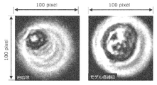
(6)電子増倍型冷却CCD(EMCCD)カメラ(フローベル社製ADT-100)を備えた蛍光顕微鏡(オリンパス社製IX83)を用いて、保持部に保持された細胞由来の画像(明視野像)を撮影し、National Instruments社製LabVIEWを用いて前記画像を取り込んだ(取り込み画像の一例を図9に示す)。
(7)取り込んだ画像から、細胞を保持した保持部それぞれに対してROI(100ピクセル×100ピクセル:0.405μm/ピクセル)を設定して処理画像を切り出し、LabVIEWを用いて2次元FFT(高速フーリエ変換)処理を行なうことで、計算により空間周波数分布画像を得た(空間周波数分布画像の一例を図10に示す)。
(8)得られた空間周波数分布画像を、空間周波数のスペクトル強度(輝度)のしきい値15で2値化処理後、LABVIEWのVision Development Moduleである粒子検出viを用いて、空間周波数分布の最大値を算出した。
(1)実施例1で作製した細胞保持手段114(図8)に、スペーサ113および電極122を組み合わせることで、図1に記載の基板100を作製した。
(2)作製した基板100に設けた導入口113aから白血球およびモデル癌細胞としてPC9細胞(肺分化型腺癌細胞)を含む溶液を導入し、交流電圧(電圧20Vpp、周波数1MHz、矩形波)を印加することで、誘電泳動力により細胞を保持部(孔径Φ30μm、深さ40μm)に保持させた。
(3)前記交流電圧を印加しながら、導入口113aから0.01%(w/v)ポリ-L-リジンを含む300mMマンニトール水溶液を導入し、3分間静置後、前記交流電圧の印加を停止し、排出口113bから前記溶液を除去した。
(4)導入口113aから細胞膜透過試薬を導入し、10分間静置することで細胞膜を透過後、排出口113bから前記溶液を除去し、導入口113aからPBS(Phosphate Buffered Saline)を導入することで収容部内に残留した細胞膜透過試薬を洗浄した。
(5)導入口113aから細胞染色液(フルオレセインイソチオシアネート(FITC)標識抗サイトケラチン(CK)抗体、R-フィコエリスリン(PE)標識抗HER2抗体、アロフィコシアニン(APC)標識抗CD45抗体、DAPI(4’,6-diamidino-2-phenylindole)をそれぞれ0.5μg/mL含む溶液)800μLを導入し、25℃で30分間反応させることで細胞標識後、導入口113aからマンニトール水溶液を導入することで洗浄した。DAPI陽性、かつCK陽性の細胞をPC9細胞として、DAPI陽性、かつCD45陽性の細胞を白血球として、それぞれ検出した。
(6)電子増倍型冷却CCD(EMCCD)カメラ(フローベル社製ADT-100)を備えた蛍光顕微鏡(オリンパス社製IX83)を用いて、保持部に保持された細胞由来の画像(明視野像)を撮影し、National Instruments社製LabVIEWを用いて前記画像を取り込んだ(取り込み画像の一例を図9に示す)。
(7)取り込んだ画像から、細胞を保持した保持部それぞれに対してROI(100ピクセル×100ピクセル:0.405μm/ピクセル)を設定して処理画像を切り出し、LabVIEWを用いて2次元FFT(高速フーリエ変換)処理を行なうことで、計算により空間周波数分布画像を得た(空間周波数分布画像の一例を図10に示す)。
(8)得られた空間周波数分布画像を、空間周波数のスペクトル強度(輝度)のしきい値15で2値化処理後、LABVIEWのVision Development Moduleである粒子検出viを用いて、空間周波数分布の最大値を算出した。
白血球(20検体)およびモデル癌(PC9)細胞(20検体)、それぞれについて空間周波数分布の最大値を算出した結果を図11に示す。なお図11では空間周波数分布の最大値を、2次元FFT処理後の空間周波数分布画像における直径のピクセル値として縦軸に示している。図11より、例えば直径35ピクセル(半径17.5ピクセル)(波長:2.314μm、空間周波数:0.4321μm-1)を空間周波数分布の最大値のしきい値とすることでPC9細胞を白血球と区別して検出できることがわかる。
実施例3 空間周波数分布の最大値に基づく癌細胞の検出(その2)
実施例2(2)で基板100に導入する細胞を、白血球ならびにモデル癌細胞としてPC9細胞、PC14細胞(肺低分化型腺癌)およびSBC3細胞(肺小細胞癌細胞)を含む溶液とした他は、実施例2と同様な方法でモデル癌細胞を検出した。結果を図12に示す。モデル癌細胞のうちPC14細胞は、PC9細胞(実施例2)と同様、例えば、空間周波数分布の最大値(2次元FFT処理後の空間周波数分布画像の直径)のしきい値を35ピクセル(波長:2.314μm、空間周波数:0.4321μm-1)とすることで、白血球と区別して検出できた。一方SBC3細胞は、白血球における空間周波数分布の最大値と一部重なる検体があり、空間周波数分布の最大値のみでは明確に白血球と区別して検出することはできなかった。
実施例2(2)で基板100に導入する細胞を、白血球ならびにモデル癌細胞としてPC9細胞、PC14細胞(肺低分化型腺癌)およびSBC3細胞(肺小細胞癌細胞)を含む溶液とした他は、実施例2と同様な方法でモデル癌細胞を検出した。結果を図12に示す。モデル癌細胞のうちPC14細胞は、PC9細胞(実施例2)と同様、例えば、空間周波数分布の最大値(2次元FFT処理後の空間周波数分布画像の直径)のしきい値を35ピクセル(波長:2.314μm、空間周波数:0.4321μm-1)とすることで、白血球と区別して検出できた。一方SBC3細胞は、白血球における空間周波数分布の最大値と一部重なる検体があり、空間周波数分布の最大値のみでは明確に白血球と区別して検出することはできなかった。
実施例4 空間周波数分布の最大値に基づく癌細胞の検出(その3)
実施例2および3では、空間周波数のスペクトル強度(2値化)のしきい値を15としたときの、空間周波数分布の最大値に基づく癌細胞の検出を行なったが、2値化しきい値を変化させたときの、空間周波数分布最大値のしきい値への影響を検討した。具体的には、実施例2(6)で得られた各細胞(PC9細胞、SBC3細胞、PC14細胞または白血球)の空間周波数分布画像から、2値化のしきい値8から15の条件で最大値を算出した。
実施例2および3では、空間周波数のスペクトル強度(2値化)のしきい値を15としたときの、空間周波数分布の最大値に基づく癌細胞の検出を行なったが、2値化しきい値を変化させたときの、空間周波数分布最大値のしきい値への影響を検討した。具体的には、実施例2(6)で得られた各細胞(PC9細胞、SBC3細胞、PC14細胞または白血球)の空間周波数分布画像から、2値化のしきい値8から15の条件で最大値を算出した。
結果を表1に示す。表1の数字は、設定した空間周波数分布の最大値のしきい値における各細胞の陽性検出率(%)を表している。また表1中、モデル癌細胞の検出率70%以上かつ白血球の偽陽性20%以下で検出可能な条件を、黒背景白文字の領域で示している。2値化のしきい値を10とした場合は空間周波数分布の最大値(空間周波数分布画像の直径)のしきい値を40ピクセルから41ピクセル(波長:1.976から2.025μm)までの間に、2値化のしきい値を11とした場合は空間周波数分布の最大値のしきい値を38ピクセルから41ピクセル(波長:1.976から2.132μm)までの間に、2値化のしきい値を12とした場合は空間周波数分布の最大値のしきい値を35ピクセルから39ピクセル(波長:2.077から2.314μm)までの間に、2値化のしきい値を13とした場合は空間周波数分布の最大値のしきい値を32ピクセルから38ピクセル(波長:2.132から2.531μm)までの間に、2値化のしきい値を14とした場合は空間周波数分布の最大値のしきい値を31ピクセルから37ピクセル(波長:2,189から2.613μm)までの間に、2値化のしきい値を15とした場合は空間周波数分布の最大値のしきい値を29ピクセルから36ピクセル(波長:2.25から2.793μm)までの間に、それぞれ設定すれば、モデル癌細胞の検出率70%以上かつ白血球の偽陽性20%以下で検出することができる。また2値化のしきい値を12とした場合は空間周波数分布の最大値のしきい値を35ピクセルから37ピクセル(波長:2.189から2.314μm)までの間に、2値化のしきい値を13とした場合は空間周波数分布の最大値のしきい値を34ピクセルから35ピクセル(波長:2.314から2.382μm)までの間に、2値化のしきい値を14とした場合は空間周波数分布の最大値のしきい値を31ピクセルから35ピクセル(波長:2.314から2.613μm)までの間に、2値化のしきい値を15とした場合は空間周波数分布の最大値のしきい値を30ピクセルから34ピクセル(波長:2.382から2.70μm)までの間に、それぞれ設定すれば、モデル癌細胞の検出率80%以上かつ白血球の偽陽性10%以下で検出することができる。なお本例では、全てのモデル癌細胞を白血球と区別して検出できる条件は見いだせなかった。

実施例5 低周波数領域における空間周波数分布に基づく癌細胞の検出(その1)
実施例3および4より空間周波数分布の最大値に基づく方法では、モデル癌細胞の一部で偽陽性(または偽陰性)になるおそれがあることがわかった(図12および表1)。そこで別の視点から空間周波数分布に基づくモデル癌細胞の検出を試みた。
実施例3および4より空間周波数分布の最大値に基づく方法では、モデル癌細胞の一部で偽陽性(または偽陰性)になるおそれがあることがわかった(図12および表1)。そこで別の視点から空間周波数分布に基づくモデル癌細胞の検出を試みた。
実施例2(6)で得られた各細胞(PC9細胞、PC14細胞、SBC3細胞または白血球)の空間周波数分布画像のうち低周波数領域、具体的には空間周波数分布画像の中心から5ピクセル(波長:8.1μm)から11ピクセル(波長:3.68μm)まで(図13中、点線領域)の領域におけるスペクトル強度の積分値を算出した。結果を図14に示す。スペクトル強度の積分値のしきい値を340とすることで、いずれのモデル癌細胞(PC9細胞、PC14細胞およびSBC3細胞)も白血球と区別して検出することができた。
実施例6 低周波数領域における空間周波数分布に基づく癌細胞の検出(その2)
実施例5より、空間周波数分布画像の中心から5ピクセルから11ピクセルまでの領域におけるスペクトル強度の積分値を用いることで、モデル癌細胞を白血球と区別して検出できることがわかったが、スペクトル強度の積分値の計算範囲を変えても同様な検出が行なえるか、検証した。
実施例5より、空間周波数分布画像の中心から5ピクセルから11ピクセルまでの領域におけるスペクトル強度の積分値を用いることで、モデル癌細胞を白血球と区別して検出できることがわかったが、スペクトル強度の積分値の計算範囲を変えても同様な検出が行なえるか、検証した。
実施例2(6)で得られた各細胞(PC9細胞、PC14細胞、SBC3細胞または白血球)の空間周波数分布画像のうち、空間周波数分布画像の中心から5ピクセル(波長:8.1μm)を起点に終点を6ピクセルから14ピクセルまで1ピクセルごとに積分範囲を設定(すなわち積分範囲を1から9ピクセルまで1ピクセルごとに設定)し、各細胞のスペクトル強度の積分値をそれぞれ算出した。結果を図15および16に示す。なお図15および16において、空間周波数のスペクトル強度積分値(横軸)は、対象細胞80個(PC9細胞、PC14細胞、SBC3細胞および白血球各20個)のうち、スペクトル強度積分値が最大であった細胞の積分値を1としたときの相対値で表している。積分範囲を4ピクセル以上(本例では5ピクセルから9ピクセルまでの範囲よりも広い範囲)とすれば、モデル癌細胞を白血球と区別して検出できることがわかる(図15(d)および(e)ならびに図16)。
実施例7 低周波数領域における空間周波数分布に基づく癌細胞の検出(その3)
実施例6では、積分範囲を1ピクセル(5ピクセルから6ピクセルまでの範囲)から9ピクセル(5ピクセルから14ピクセルまでの範囲)としたときの、モデル癌細胞と白血球とのスペクトル強度積分値を比較したが、さらに積分範囲を15ピクセル(5ピクセルから20ピクセルまでの範囲)、25ピクセル(5ピクセルから30ピクセルまでの範囲)、35ピクセル(5ピクセルから40ピクセルまでの範囲)、45ピクセル(5ピクセルから50ピクセルまでの範囲)および65ピクセル(5ピクセルから70ピクセルまでの範囲)に拡大し、同様に検討した。
実施例6では、積分範囲を1ピクセル(5ピクセルから6ピクセルまでの範囲)から9ピクセル(5ピクセルから14ピクセルまでの範囲)としたときの、モデル癌細胞と白血球とのスペクトル強度積分値を比較したが、さらに積分範囲を15ピクセル(5ピクセルから20ピクセルまでの範囲)、25ピクセル(5ピクセルから30ピクセルまでの範囲)、35ピクセル(5ピクセルから40ピクセルまでの範囲)、45ピクセル(5ピクセルから50ピクセルまでの範囲)および65ピクセル(5ピクセルから70ピクセルまでの範囲)に拡大し、同様に検討した。
各積分領域について、スペクトル強度積分値が最大であった細胞の積分値を1としたときの、スペクトル強度積分値が最小のモデル癌細胞(PC9細胞、SBC3細胞またはPC14細胞)の相対値とスペクトル強度積分値が最大の白血球細胞の相対値との差をプロットした図を図17に示す。なお図17は実施例6の結果もあわせてプロットしている。図17より、積分範囲が4ピクセルから45ピクセルの間であれば、スペクトル強度積分値が最小のモデル癌細胞の相対値とスペクトル強度積分値が最大の白血球細胞の相対値との差が0以上であり、モデル癌細胞を白血球と区別して検出できることがわかる。また積分範囲を5ピクセルから15ピクセルまでの間とすると、モデル癌細胞を白血球とより区別して検出できることがわかる。
本発明を詳細に、また特定の実施態様を参照して説明してきたが、本発明の本質と範囲を逸脱することなく様々な変更や修正を加えることには当業者にとって明らかである。
なお、2015年12月15日に出願された日本特許出願2015-243939号の明細書、特許請求の範囲、図面及び要約書の全内容をここに引用し、本発明の明細書の開示として、取り入れるものである。
100:基板
110:細胞導入保持手段
111:遮光部材
112:絶縁体
111a、112a:貫通孔
113:スペーサ
113a:導入口
113b:排出口
113c:貫通部
114:細胞保持手段
115、116:位置検出部(四角マーク)
117:位置検出部(十字マーク)
121、122:電極
130:導線
140:信号発生器
150:保持部
200:細胞
210:目的細胞
310:ベース
320:基板移動部
330:照射部
340:検出部(対物レンズ)
350:画像取り込み部(画像取得カメラ)
360:解析部
410:ノズル
420:吸引吐出用ポンプ
430:ノズル移動部
440:ノズル照射部
451:ノズル照射部からの光
452:ノズル先端部から発せられる光
460:ノズル導光部
500:回収チューブ
600:誘電泳動力
700:接着物質
110:細胞導入保持手段
111:遮光部材
112:絶縁体
111a、112a:貫通孔
113:スペーサ
113a:導入口
113b:排出口
113c:貫通部
114:細胞保持手段
115、116:位置検出部(四角マーク)
117:位置検出部(十字マーク)
121、122:電極
130:導線
140:信号発生器
150:保持部
200:細胞
210:目的細胞
310:ベース
320:基板移動部
330:照射部
340:検出部(対物レンズ)
350:画像取り込み部(画像取得カメラ)
360:解析部
410:ノズル
420:吸引吐出用ポンプ
430:ノズル移動部
440:ノズル照射部
451:ノズル照射部からの光
452:ノズル先端部から発せられる光
460:ノズル導光部
500:回収チューブ
600:誘電泳動力
700:接着物質
Claims (8)
- 細胞に光を照射する細胞照射手段と、細胞照射手段で照射して得られる前記細胞由来の画像を取り込む画像取り込み手段と、画像取り込み手段で取り込まれた前記画像に対して2次元フーリエ変換を行なう画像変換手段と、画像変換手段で変換された画像の空間周波数分布に基づき目的細胞を検出する画像検出手段と、を備えた細胞検出装置であって、
前記画像検出手段による目的細胞の検出を、画像変換手段で変換された画像の低周波数領域における空間周波数分布または画像変換手段で変換された画像の空間周波数分布の最大値のうち少なくともいずれか一つに基づき行なう、前記装置。 - 細胞に光を照射する細胞照射手段と、細胞照射手段で照射して得られる前記細胞由来の画像を取り込む画像取り込み手段と、画像取り込み手段で取り込まれた前記画像に対して2次元フーリエ変換を行なう画像変換手段と、画像変換手段で変換された画像の空間周波数分布に基づき細胞を検出する画像検出手段と、を備えた細胞検出装置であって、
前記装置に、画像取り込み手段で取り込まれた前記画像の蛍光または発光を検出する光検出手段をさらに備え、かつ目的細胞の検出を、画像検出手段における画像変換手段で変換された画像の低周波数領域における空間周波数分布または画像変換手段で変換された画像の空間周波数分布の最大値のうち少なくともいずれか一つに基づく検出結果、および光検出手段における蛍光検出または発光検出結果に基づき行なう、前記装置。 - 細胞に光を照射する細胞照射手段と、細胞照射手段で照射して得られる前記細胞由来の画像を取り込む画像取り込み手段と、画像取り込み手段で取り込まれた前記画像に対して2次元フーリエ変換を行なう画像変換手段と、画像変換手段で変換された画像の空間周波数分布に基づき目的細胞を検出する画像検出手段と、画像検出手段で検出した前記目的細胞をノズルによる吸引吐出により回収する回収手段と、を備えた細胞回収装置であって、
前記画像検出手段による目的細胞の検出を、画像変換手段で変換された画像の低周波数領域における空間周波数分布または画像変換手段で変換された画像の空間周波数分布の最大値のうち少なくともいずれか一つに基づき行なう、前記装置。 - 細胞に光を照射する細胞照射手段と、細胞照射手段で照射して得られる前記細胞由来の画像を取り込む画像取り込み手段と、画像取り込み手段で取り込まれた前記画像に対して2次元フーリエ変換を行なう画像変換手段と、画像変換手段で変換された画像の空間周波数分布に基づき細胞を検出する画像検出手段と、ノズルによる吸引吐出により細胞を回収する回収手段と、を備えた細胞回収装置であって、
前記装置に、画像取り込み手段で取り込まれた前記画像の蛍光または発光を検出する光検出手段をさらに備え、かつ回収手段で回収する目的細胞の検出を、画像検出手段における画像変換手段で変換された画像の低周波数領域における空間周波数分布または画像変換手段で変換された画像の空間周波数分布の最大値のうち少なくともいずれか一つに基づく検出結果、および光検出手段における蛍光検出または発光検出結果に基づき行なう、前記装置。 - 回収手段における前記ノズルの先端部が透光性材料で形成されており、かつ前記ノズルに光を照射するためのノズル照射部およびノズル照射部で照射した光を前記ノズルの先端部に導くためのノズル導光部を前記回収手段にさらに設けた、請求項3または4に記載の装置。
- 画像検出手段による細胞の検出を、画像変換手段で変換された画像の低周波数領域における空間周波数分布および画像変換手段で変換された画像の空間周波数分布の最大値に基づき行なう、請求項1から5のいずれか一項に記載の装置。
- 細胞を保持する保持部を有した細胞保持手段をさらに備え、かつ細胞照射手段が前記保持部に保持された細胞に光を照射する、請求項1から6のいずれか一項に記載の装置。
- 細胞照射手段から照射される光により蛍光を発する位置検出部を細胞保持手段にさらに設けた、請求項7に記載の装置。
Applications Claiming Priority (2)
| Application Number | Priority Date | Filing Date | Title |
|---|---|---|---|
| JP2015243939 | 2015-12-15 | ||
| JP2015-243939 | 2015-12-15 |
Publications (1)
| Publication Number | Publication Date |
|---|---|
| WO2017104556A1 true WO2017104556A1 (ja) | 2017-06-22 |
Family
ID=59056703
Family Applications (1)
| Application Number | Title | Priority Date | Filing Date |
|---|---|---|---|
| PCT/JP2016/086676 Ceased WO2017104556A1 (ja) | 2015-12-15 | 2016-12-09 | 細胞検出装置および細胞回収装置 |
Country Status (2)
| Country | Link |
|---|---|
| JP (1) | JP2017108738A (ja) |
| WO (1) | WO2017104556A1 (ja) |
Cited By (3)
| Publication number | Priority date | Publication date | Assignee | Title |
|---|---|---|---|---|
| JP2021083431A (ja) * | 2019-11-29 | 2021-06-03 | シスメックス株式会社 | 細胞解析方法、細胞解析装置、細胞解析システム、及び細胞解析プログラム |
| JP2021128014A (ja) * | 2020-02-12 | 2021-09-02 | 東ソー株式会社 | 細胞の回収方法および検出方法 |
| US11927520B2 (en) | 2019-05-30 | 2024-03-12 | Hewlett-Packard Development Company, L.P. | Rotating levitated particle imaging |
Families Citing this family (5)
| Publication number | Priority date | Publication date | Assignee | Title |
|---|---|---|---|---|
| WO2018207454A1 (ja) * | 2017-05-12 | 2018-11-15 | 株式会社ニコン | 対象物操作装置、及び対象物操作方法 |
| KR101926117B1 (ko) * | 2017-08-18 | 2018-12-06 | 주식회사 싸이토젠 | 안드로겐 수용체의 변이체 기반 전립선암환자 스크리닝 방법 |
| JP2019101021A (ja) * | 2017-11-28 | 2019-06-24 | 東ソー株式会社 | 生体物質保持装置、および生体物質の検出方法 |
| JP2022012314A (ja) | 2020-07-01 | 2022-01-17 | ネッパジーン株式会社 | 細胞回収装置 |
| JP7644958B2 (ja) * | 2020-12-14 | 2025-03-13 | ナノティス株式会社 | 試料中の被検出物質を検出する方法 |
Citations (3)
| Publication number | Priority date | Publication date | Assignee | Title |
|---|---|---|---|---|
| JP2009053200A (ja) * | 2008-09-22 | 2009-03-12 | Sumitomo Osaka Cement Co Ltd | 物体識別装置 |
| JP2014132897A (ja) * | 2012-12-12 | 2014-07-24 | Hitachi Chemical Co Ltd | がん細胞単離装置及びがん細胞単離方法 |
| JP2015039344A (ja) * | 2013-08-22 | 2015-03-02 | 富士フイルム株式会社 | 観察画像判定装置および方法並びにプログラム |
Family Cites Families (1)
| Publication number | Priority date | Publication date | Assignee | Title |
|---|---|---|---|---|
| EP2381255A1 (en) * | 2003-09-25 | 2011-10-26 | Toyama Prefecture | Microwell array chip and its manufacturing method |
-
2016
- 2016-12-08 JP JP2016238654A patent/JP2017108738A/ja active Pending
- 2016-12-09 WO PCT/JP2016/086676 patent/WO2017104556A1/ja not_active Ceased
Patent Citations (3)
| Publication number | Priority date | Publication date | Assignee | Title |
|---|---|---|---|---|
| JP2009053200A (ja) * | 2008-09-22 | 2009-03-12 | Sumitomo Osaka Cement Co Ltd | 物体識別装置 |
| JP2014132897A (ja) * | 2012-12-12 | 2014-07-24 | Hitachi Chemical Co Ltd | がん細胞単離装置及びがん細胞単離方法 |
| JP2015039344A (ja) * | 2013-08-22 | 2015-03-02 | 富士フイルム株式会社 | 観察画像判定装置および方法並びにプログラム |
Cited By (6)
| Publication number | Priority date | Publication date | Assignee | Title |
|---|---|---|---|---|
| US11927520B2 (en) | 2019-05-30 | 2024-03-12 | Hewlett-Packard Development Company, L.P. | Rotating levitated particle imaging |
| JP2021083431A (ja) * | 2019-11-29 | 2021-06-03 | シスメックス株式会社 | 細胞解析方法、細胞解析装置、細胞解析システム、及び細胞解析プログラム |
| US12020492B2 (en) | 2019-11-29 | 2024-06-25 | Sysmex Corporation | Cell analysis method, cell analysis device, and cell analysis system |
| JP7545202B2 (ja) | 2019-11-29 | 2024-09-04 | シスメックス株式会社 | 細胞解析方法、細胞解析装置、細胞解析システム、及び細胞解析プログラム |
| JP2021128014A (ja) * | 2020-02-12 | 2021-09-02 | 東ソー株式会社 | 細胞の回収方法および検出方法 |
| JP7480515B2 (ja) | 2020-02-12 | 2024-05-10 | 東ソー株式会社 | 細胞の回収方法および検出方法 |
Also Published As
| Publication number | Publication date |
|---|---|
| JP2017108738A (ja) | 2017-06-22 |
Similar Documents
| Publication | Publication Date | Title |
|---|---|---|
| WO2017104556A1 (ja) | 細胞検出装置および細胞回収装置 | |
| US12007548B2 (en) | System and method for characterizing particulates in a fluid sample | |
| CN109459438B (zh) | 一种缺陷检测设备及方法 | |
| US11327004B2 (en) | Live-cell computed tomography | |
| US11874228B2 (en) | Methods for identification of particles in a fluid sample | |
| JP3700035B2 (ja) | 稀少出現ほ乳類細胞を検出しカウントするための装置及び方法 | |
| JP5716738B2 (ja) | 細胞の検出方法及び細胞検出システム | |
| CN114556084A (zh) | 细胞分析装置系统及细胞分析方法 | |
| JP5078920B2 (ja) | 液面検出装置及び方法 | |
| JP2005524833A (ja) | 分析細胞イメージング用のデバイスおよび方法 | |
| US20250349137A1 (en) | Methods for distinguishing particles in a fluid sample | |
| JP7830346B2 (ja) | 感度増強のためのアグリゲーション誘発によるアッセイ | |
| WO2023008369A1 (ja) | 細胞自家蛍光の画像を用いて細胞を分類する方法及び解析装置 | |
| JP2016174578A (ja) | 微小粒子選別装置および前記装置を備えた微小粒子回収装置 | |
| Avci et al. | An optofluidic platform for cell-counting applications | |
| JP6572547B2 (ja) | 微小粒子回収装置 | |
| JP2010032327A (ja) | 被検出物質検出方法および被検出物質検出装置ならびに深さ位置計測方法および深さ位置計測装置 | |
| JP2009207392A (ja) | 増幅核酸の解析方法及び解析装置 | |
| JP2006081427A (ja) | 菌検出方法および菌計数装置 | |
| JP2008304298A (ja) | 細菌判別装置および細菌判別方法 | |
| US20240077479A1 (en) | Detection system and method for the migrating cell | |
| JP6172021B2 (ja) | 細胞整列チップ、その製造方法、標的細胞の検出方法、標的細胞の検出装置および細胞捕捉不良領域の検出方法 | |
| JP2016142565A (ja) | 目的細胞の検出方法および目的細胞検出システム | |
| CN108802387A (zh) | 一种用于检测循环肿瘤细胞的仪器 | |
| JP4426777B2 (ja) | 微生物計数方法 |
Legal Events
| Date | Code | Title | Description |
|---|---|---|---|
| 121 | Ep: the epo has been informed by wipo that ep was designated in this application |
Ref document number: 16875536 Country of ref document: EP Kind code of ref document: A1 |
|
| NENP | Non-entry into the national phase |
Ref country code: DE |
|
| 122 | Ep: pct application non-entry in european phase |
Ref document number: 16875536 Country of ref document: EP Kind code of ref document: A1 |