WO2018207454A1 - 対象物操作装置、及び対象物操作方法 - Google Patents
対象物操作装置、及び対象物操作方法 Download PDFInfo
- Publication number
- WO2018207454A1 WO2018207454A1 PCT/JP2018/009683 JP2018009683W WO2018207454A1 WO 2018207454 A1 WO2018207454 A1 WO 2018207454A1 JP 2018009683 W JP2018009683 W JP 2018009683W WO 2018207454 A1 WO2018207454 A1 WO 2018207454A1
- Authority
- WO
- WIPO (PCT)
- Prior art keywords
- cell
- wall
- chamber
- operating device
- liquid
- Prior art date
Links
Images


Classifications
-
- G—PHYSICS
- G02—OPTICS
- G02B—OPTICAL ELEMENTS, SYSTEMS OR APPARATUS
- G02B21/00—Microscopes
- G02B21/36—Microscopes arranged for photographic purposes or projection purposes or digital imaging or video purposes including associated control and data processing arrangements
- G02B21/365—Control or image processing arrangements for digital or video microscopes
-
- B—PERFORMING OPERATIONS; TRANSPORTING
- B01—PHYSICAL OR CHEMICAL PROCESSES OR APPARATUS IN GENERAL
- B01L—CHEMICAL OR PHYSICAL LABORATORY APPARATUS FOR GENERAL USE
- B01L3/00—Containers or dishes for laboratory use, e.g. laboratory glassware; Droppers
- B01L3/50—Containers for the purpose of retaining a material to be analysed, e.g. test tubes
- B01L3/502—Containers for the purpose of retaining a material to be analysed, e.g. test tubes with fluid transport, e.g. in multi-compartment structures
-
- C—CHEMISTRY; METALLURGY
- C12—BIOCHEMISTRY; BEER; SPIRITS; WINE; VINEGAR; MICROBIOLOGY; ENZYMOLOGY; MUTATION OR GENETIC ENGINEERING
- C12M—APPARATUS FOR ENZYMOLOGY OR MICROBIOLOGY; APPARATUS FOR CULTURING MICROORGANISMS FOR PRODUCING BIOMASS, FOR GROWING CELLS OR FOR OBTAINING FERMENTATION OR METABOLIC PRODUCTS, i.e. BIOREACTORS OR FERMENTERS
- C12M23/00—Constructional details, e.g. recesses, hinges
- C12M23/02—Form or structure of the vessel
- C12M23/16—Microfluidic devices; Capillary tubes
-
- C—CHEMISTRY; METALLURGY
- C12—BIOCHEMISTRY; BEER; SPIRITS; WINE; VINEGAR; MICROBIOLOGY; ENZYMOLOGY; MUTATION OR GENETIC ENGINEERING
- C12M—APPARATUS FOR ENZYMOLOGY OR MICROBIOLOGY; APPARATUS FOR CULTURING MICROORGANISMS FOR PRODUCING BIOMASS, FOR GROWING CELLS OR FOR OBTAINING FERMENTATION OR METABOLIC PRODUCTS, i.e. BIOREACTORS OR FERMENTERS
- C12M23/00—Constructional details, e.g. recesses, hinges
- C12M23/34—Internal compartments or partitions
-
- C—CHEMISTRY; METALLURGY
- C12—BIOCHEMISTRY; BEER; SPIRITS; WINE; VINEGAR; MICROBIOLOGY; ENZYMOLOGY; MUTATION OR GENETIC ENGINEERING
- C12M—APPARATUS FOR ENZYMOLOGY OR MICROBIOLOGY; APPARATUS FOR CULTURING MICROORGANISMS FOR PRODUCING BIOMASS, FOR GROWING CELLS OR FOR OBTAINING FERMENTATION OR METABOLIC PRODUCTS, i.e. BIOREACTORS OR FERMENTERS
- C12M31/00—Means for providing, directing, scattering or concentrating light
- C12M31/10—Means for providing, directing, scattering or concentrating light by light emitting elements located inside the reactor, e.g. LED or OLED
-
- C—CHEMISTRY; METALLURGY
- C12—BIOCHEMISTRY; BEER; SPIRITS; WINE; VINEGAR; MICROBIOLOGY; ENZYMOLOGY; MUTATION OR GENETIC ENGINEERING
- C12M—APPARATUS FOR ENZYMOLOGY OR MICROBIOLOGY; APPARATUS FOR CULTURING MICROORGANISMS FOR PRODUCING BIOMASS, FOR GROWING CELLS OR FOR OBTAINING FERMENTATION OR METABOLIC PRODUCTS, i.e. BIOREACTORS OR FERMENTERS
- C12M35/00—Means for application of stress for stimulating the growth of microorganisms or the generation of fermentation or metabolic products; Means for electroporation or cell fusion
- C12M35/02—Electrical or electromagnetic means, e.g. for electroporation or for cell fusion
-
- C—CHEMISTRY; METALLURGY
- C12—BIOCHEMISTRY; BEER; SPIRITS; WINE; VINEGAR; MICROBIOLOGY; ENZYMOLOGY; MUTATION OR GENETIC ENGINEERING
- C12M—APPARATUS FOR ENZYMOLOGY OR MICROBIOLOGY; APPARATUS FOR CULTURING MICROORGANISMS FOR PRODUCING BIOMASS, FOR GROWING CELLS OR FOR OBTAINING FERMENTATION OR METABOLIC PRODUCTS, i.e. BIOREACTORS OR FERMENTERS
- C12M41/00—Means for regulation, monitoring, measurement or control, e.g. flow regulation
- C12M41/48—Automatic or computerized control
-
- G—PHYSICS
- G02—OPTICS
- G02B—OPTICAL ELEMENTS, SYSTEMS OR APPARATUS
- G02B21/00—Microscopes
- G02B21/36—Microscopes arranged for photographic purposes or projection purposes or digital imaging or video purposes including associated control and data processing arrangements
- G02B21/361—Optical details, e.g. image relay to the camera or image sensor
-
- G—PHYSICS
- G06—COMPUTING; CALCULATING OR COUNTING
- G06T—IMAGE DATA PROCESSING OR GENERATION, IN GENERAL
- G06T7/00—Image analysis
- G06T7/0002—Inspection of images, e.g. flaw detection
- G06T7/0012—Biomedical image inspection
-
- B—PERFORMING OPERATIONS; TRANSPORTING
- B01—PHYSICAL OR CHEMICAL PROCESSES OR APPARATUS IN GENERAL
- B01L—CHEMICAL OR PHYSICAL LABORATORY APPARATUS FOR GENERAL USE
- B01L2200/00—Solutions for specific problems relating to chemical or physical laboratory apparatus
- B01L2200/06—Fluid handling related problems
- B01L2200/0636—Focussing flows, e.g. to laminate flows
-
- G—PHYSICS
- G06—COMPUTING; CALCULATING OR COUNTING
- G06T—IMAGE DATA PROCESSING OR GENERATION, IN GENERAL
- G06T2207/00—Indexing scheme for image analysis or image enhancement
- G06T2207/10—Image acquisition modality
- G06T2207/10056—Microscopic image
Definitions
- the present invention relates to an object operating device and an object operating method.
- An object operation device that is an apparatus that performs an operation on an object such as particles or cells is known.
- the particle or cell is, for example, a particle or cell having a diameter of about 100 micrometers or less.
- a method of an apparatus for performing an operation on an object a method using an electrode array (see, for example, Patent Document 1) or a method in which an electric field is generated at an irradiation location by irradiating pattern light (for example, see Patent Document 2). There is.
- an apparatus that can observe an object to be operated in an object operation apparatus.
- the object operating device capable of observing the object the object can be distinguished by observing the observation image, which is an image in which the object is observed, so the object to be selected is selected from the observation image.
- the observation image which is an image in which the object is observed
- the object to be selected is selected from the observation image.
- the chamber for storing the liquid and the target the target moving unit for moving the target stored in the chamber in the chamber, It is a target object operating device provided with the holding mechanism for holding a target object irrespective of the flow of a liquid.
- moving an object contained in a chamber containing a liquid and an object within the chamber And holding the moved object in the movement regardless of the liquid flow when the liquid in the chamber flows.
- selecting an object contained in a chamber containing a liquid and an object comprising: holding a selected object in selecting regardless of the flow of the liquid when the liquid in the chamber flows.
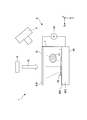
- FIG. 1 is a perspective view showing an example of the configuration of the object operating device 1 according to the present embodiment.
- FIG. 2 is sectional drawing which shows an example of a structure of the target object operating device 1 by this embodiment.
- the object operating device 1 is an apparatus that operates an object. In the following description, the case where the object is a cell will be described, but the object may be a particle.
- the object operation device 1 includes a cell / water input port 2, a chamber 3, a cell / water recovery port 4, a control unit 5, a cell operation unit 6, a separation unit 7, a camera 8, and a light irradiation unit.
- the cell / water inlet 2 is connected to the chamber 3.
- the cell / water inlet 2 is a supply unit that supplies the liquid W to the chamber 3. That is, the chamber 3 includes a supply unit that supplies the liquid W to the chamber 3.
- the liquid W is, for example, water or a buffer solution. In this embodiment, the liquid W is a buffer solution as an example.
- the electric conductivity of this buffer solution is, for example, 10 mS / m.
- the cell / water inlet 2 supplies the cells to the chamber 3.
- the chamber 3 is filled with the liquid W supplied from the cell / water inlet 2.
- cells are arranged in the filled liquid W. That is, the chamber 3 accommodates the liquid and the object.
- the cells C1 and C2 are arranged in the liquid W.
- the cell C1 is an example of a cell to be sorted
- the cell C2 is an example of a cell that is not to be sorted.
- the number of cells arranged in the chamber 3 may be two or more, and the object manipulating apparatus 1 can operate a plurality of cells among the cells arranged in the chamber 3 as selection targets at the same time.
- the cell / water recovery port 4 is connected to the chamber 3.
- the cell / water recovery port 4 can recover the liquid W discharged from the chamber 3 by the flow of the liquid W generated in the chamber 3.
- the cell / water recovery port 4 can discharge cells excluding cells isolated by the isolation part 7 in the chamber 3 by the flow of the liquid W generated in the chamber 3.
- the cell / water recovery port 4 allows the cell / water recovery port 4 to remove the cells except the cells isolated by the isolation unit 7 in the chamber 3. It is the discharge part discharged
- the flow of the liquid W in the chamber 3 is generated, for example, when the liquid W is supplied from the cell / water inlet 2.
- the control unit 5 controls the object operating device 1.
- the control unit 5 controls the object operating device 1 by controlling the cell operation unit 6, the cell / water input port 2, and the cell / water recovery port 4.
- the cell operation unit 6 moves the cells accommodated in the chamber 3.
- the cell operation unit 6 is an example of a target moving unit that moves a target object accommodated in the chamber 3.
- the cell operation unit 6 moves the cells accommodated in the chamber 3 by an electric field generated by irradiation of light around the cells accommodated in the chamber 3. That is, the cell operation unit 6 moves the object accommodated in the chamber 3 within the chamber 3.
- the cell operation unit 6 moves the object accommodated in the chamber 3 by an electric field generated by light irradiation around the object accommodated in the chamber 3. That is, the cell operation unit 6 moves the object by the electric field E generated around the object.
- the cell operation unit 6 includes a first electrode 60, a second electrode 61, and an AC voltage source 62.
- the AC voltage source 62 is provided between the first electrode 60 and the second electrode 61, and applies an AC voltage between the first electrode 60 and the second electrode 61. That is, the cell operation unit 6 includes a first electrode and a second electrode to which a voltage is applied.
- the isolation unit 7 is arranged in the chamber 3 and isolates the cells moved by the cell operation unit 6.
- the isolation unit 7 isolates the object moved by the cell operation unit 6.
- the isolation unit 7 can isolate the object from the flow of the liquid W generated in the chamber 3.
- the isolation unit 7 includes an isolation unit 7-1 to an isolation unit 7-5.
- the shape of the isolation part 7-1 to the isolation part 7-5 is, for example, a triangular prism.
- an inlet 72 is formed by the first wall 70 of the isolation part 7-4 and the second wall 71 of the isolation part 7-5.
- the first wall 70 is one of the side surfaces of the separating portion 7-4 having a triangular prism shape
- the second wall 71 is one of the side surfaces of the separating portion 7-5 having a triangular prism shape.
- the wall surface of the first wall 70 and the wall surface of the second wall 71 are non-parallel, and the distance between the wall surface of the first wall 70 and the wall surface of the second wall 71 is formed so as to extend along the X-axis direction. Is done.
- the cell C ⁇ b> 1 moved by the cell operation unit 6 enters the isolation unit 7 from the inlet 72.
- the wall surrounding the target object has the first wall 70 and the second wall 71, and the first wall 70 and the second wall 71 form the entrance 72, and the target movement
- the object to be moved by the unit (cell manipulation unit 6) is surrounded by the first wall 70 and the second wall 71 through the inlet 72.
- the wall surface of the first wall 70 and the wall surface of the second wall 71 of the isolation part 7 are non-parallel.
- the wall surface of the first wall 70 and the wall surface of the second wall 71 face each other.
- the camera 8 observes the cell C1 in the chamber 3.
- the position of the cell C1 to be sorted in the chamber 3 is specified by observation with the camera 8, and the irradiation position of the light EL is determined as described above.
- the light irradiation unit 9 irradiates the cell operation unit 6 with light EL for generating an electric field E for operation by the cell operation unit 6.
- FIG. 3 is a diagram illustrating an example of a method for moving the cell C1 by the cell operation unit 6 according to the present embodiment.
- the cell operation unit 6 moves the cells using optoelectronic tweezers (OET: Optoelectronic tweezers).
- OET optoelectronic tweezers
- the OET changes the potential of the first electrode 60 with respect to the second electrode 61 using a light beam, and moves cells by dielectrophoresis (DEP: Dielectricphoresis) due to a non-uniform electric field generated by the change in the potential.
- DEP dielectrophoresis
- Technology. DEP is known as a technique for manipulating cells in the fields of cell biology and colloid science.
- cell movement is controlled by exposing the cell to a non-uniform electric field.
- a method of generating an electric field generated between the first electrode 60 and the second electrode 61 will be described.
- the first electrode 60 includes, for example, an ITO (Indium Tin Oxide) glass 600 and a photoelectric layer 601.
- the first electrode 60 includes a photosensitive layer 601 on the surface of the upper layer.
- the photoelectric layer 601 is, for example, amorphous silicon.
- the second electrode 61 is a transparent electrode.
- the transparent electrode is, for example, ITO glass.
- the OET is biased by a single AC voltage source 62. In the absence of light EL illumination, most of the voltage drops across the photosensitive layer 601 of the first electrode 60 because its impedance is much higher than the liquid W.
- the light irradiation unit 9 irradiates the surface of the first electrode 60 with the light EL from the second electrode 61 side.
- the light EL that has passed through the second electrode 61 is irradiated onto the surface of the first electrode 60.
- a non-uniform electric field E is generated between the light irradiation region VE that is the surface region of the first electrode 60 irradiated with the light EL and the second electrode 61. That is, an electric field E is generated between the light irradiation region VE irradiated by the light irradiation unit 9 and the second electrode 61. Therefore, in the object operating device 1, the electric field E is generated by irradiating light around the object.
- the conductivity of the photoelectric layer 601 increases in the light irradiation region VE where the illumination strikes in orders of magnitude, shifting the voltage drop to the liquid W.
- the light irradiation region VE that is a region irradiated with the light EL of the photoelectric layer 601 functions as an electrode when the light EL is irradiated. That is, the light irradiation region VE is a virtual electrode.
- the 2nd electrode 61 is a transparent electrode, and the light EL which passed the transparent electrode is irradiated to the light irradiation area
- the resulting DEP force moves the cell C1 to be sorted.
- the DEP force is controlled by the frequency of the applied AC signal and can be positive or negative. Negative DEP forces repel cells from the high electric field region. On the other hand, positive DEP forces tend to attract multiple cells.
- the AC voltage source 62 applies an AC voltage having a peak-to-peak voltage of about 10 Vpp at a frequency of 100 kHz to the first electrode 60 and the second electrode 61.
- the cell operation unit 6 can move the cell C1 by irradiating the light EL so as to surround the cell C1 and moving the irradiation position.
- the liquid W is filled between the first electrode 60 and the second electrode 61, and the cell C1 is arranged in the filled liquid W.
- an electric field generated by irradiation with the light EL can be disposed between the first electrode 60 and the second electrode 61.
- the cell C1 is attracted to the light wall by a positive DEP force.
- this embodiment demonstrates an example using the positive DEP force in which the cell operation part 6 attracts several particle
- the cell manipulation unit 6 may use a negative DEP force.
- FIG. 4 an example when the cell operation part 6 uses a negative DEP force is demonstrated.
- FIG. 4 is a diagram illustrating an example of a method for moving the cell C1 by the cell operation unit 6 according to the present embodiment.
- the cells Ca1 to Ca3 repel from the high electric field region due to the negative DEP force. Negative DEP forces are preferred for cages for capturing single cells, which can be easily formed by a wall of light around the cells.
- the direction shown in FIG. 4 and the example shown in FIG. 3 are different in the direction in which the light EL is irradiated in the Z-axis direction.
- the light EL is irradiated from the second electrode 61 side, and the light EL that has passed through the second electrode 61 is irradiated to the surface of the first electrode 60.
- the light EL is irradiated from the first electrode 60 side, and the light EL that has passed through the first electrode 60 is irradiated to the surface of the first electrode 60.
- the light EL is irradiated from the first electrode 60 side or the second electrode 61 side depends on the transmittance, electric conductivity, etc. of the first electrode 60, the second electrode 61, and the liquid W. It may be changed.
- the DEP force is handled on the photoconductive surface of the first electrode 60 using a light beam.
- OET optically forms a virtual electrode pattern on the photoconductive surface of the first electrode 60.
- the virtual electrode pattern on the photoconductive surface of the first electrode 60 has the shape of the light irradiation region VE on the photoconductive surface of the first electrode 60.
- the size of the virtual electrode can be continuously changed up to the diffraction limit of the objective lens of the camera 8 depending on the light spot size.
- the cell operation unit 6 can use digital light projection using an incoherent light source to operate the cells.
- the cell manipulation unit 6 uses “light walls” that confine a plurality of microparticles (cells) in a plurality of virtual microfluidic channels.
- Amorphous silicon has a dark conductivity of about 0.01 ⁇ S / m to 1 ⁇ S / m. Thus, in the dark, amorphous silicon has a much lower conductivity than liquid W, which has a conductivity of 10 mS / m, resulting in a major drop in the voltage applied across the photosensitive layer 601.
- the incident light focused on the photosensitive layer 601 has a substantial drop in voltage across the liquid W in the chamber 3, so that the electrical conductivity is substantially increased and the electric field E surrounding the light irradiation region VE is increased. Form. In this way, the light incident on the cell operation unit 6 can pattern the virtual electrode for dielectrophoresis.
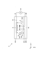
- FIG. 5 is a diagram illustrating an example of the automatic light operation system S based on the microvision according to the present embodiment.
- the automatic light manipulation system S pattern recognition based on microvision and an OET device D4 for processing fine particles are integrated.
- the automatic light manipulation system S automatically recognizes the position and size of randomly dispersed cells, generates a direct image pattern for capturing and transporting the cell C1 to be selected, and moves the movement path of the cell C1. calculate.
- the OET device D4 and a programmable digital micromirror device display (DMD: Digital Mirror Device) microdisplay D1 are integrated into an 800,000,000-mm effective area.
- a virtual electrode of the pixel can be generated.
- Each virtual electrode can be individually controlled for parallel operation of multiple cells.
- the automatic light manipulation system S is constituted by an OET device D4 including a microscope imaging means and a mechanism for recording the characteristics and positions of cells.
- the movement of the cells is controlled by projecting the light EL generated from the light source D2 and reflected from the DMD microdisplay D1 onto the OET device D4 through the objective lens D3.
- the optical pattern is generated according to the position and characteristics of the cells recorded by the microscope imaging means combining image analysis and pattern recognition algorithm.
- the image is collected through a lens D5 to a CCD imager D6 and the data is processed to control the pattern of light produced.
- the microscope image is analyzed in an image analysis circuit and / or routine S1.
- the image data is then processed using a pattern recognition circuit and / or routine S2.
- the actual pattern recognition is performed for the desired purpose of the application, from which subsequent patterns are generated by the pattern generation circuit and / or routine S3.
- the pattern is converted by the DMD circuit and / or routine S4 to control the operation of the programmable DMD microdisplay D1.
- the OET device D4 corresponds to the cell operation unit 6 shown in FIGS.
- the above-described image analysis circuit and / or routine S1, pattern recognition circuit and / or routine S2, pattern generation circuit and / or routine S3, and DMD circuit and / or routine S4 are included in the control unit 5 in FIGS. Realized as a configuration or function.
- the DMD micro display D1, the light source D2, and the objective lens D3 function as the light irradiation unit 9 of the object operating device 1.
- the light source D2 is a halogen lamp as an example, and illuminates the programmable DMD microdisplay D1.
- an inverted microscope is used as the lens D5 and the CCD imager D6.
- the software of the control unit 5 analyzes the real-time video frame and generates a corresponding optical pattern that captures and moves the cell C1. These patterns are then transferred to the DMD microdisplay D1, allowing direct control of individual pixels.
- the resolution of the projected optical image on the OET device D4 is 1.3 ⁇ m defined by the pixel size (13 ⁇ m) of the DMD microdisplay D1.
- the effective optical operation area on the OET device D4 is 1.3 mm ⁇ 1 mm.
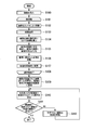
- FIG. 6 is a diagram illustrating an example of the flow of the cell manipulation process according to the present embodiment.
- the object operating device 1 inputs the cells C1 and C2 from the cell / water input port 2 into the chamber 3 (step S100).
- the chamber 3 accommodates the input cells C1 and C2.
- the cells C1 and C2 are introduced into the cell operation unit 6 by being accommodated in the chamber 3.
- the introduction of the cell into the cell operation unit 6 means that the cell is disposed in the liquid W filled between the first electrode 60 and the second electrode 61.
- the cell operation unit 6 repeats the process of arranging the cells in the isolation unit 7 for each cell to be selected (step S101).
- the object manipulation device 1 observes the cells introduced into the cell manipulation unit 6 with the camera 8 (step S102).
- the target object operating device 1 selects a desired cell from the cells introduced into the cell operation unit 6 using the observation image obtained by the camera 8 (step S103). That is, the object operating device 1 selects an object to be accommodated in the chamber 3 that accommodates the liquid and the object.
- the cells to be selected may be marked in advance before introduction into the cell operation unit 6. Here, the marking on the cell may be performed, for example, by incorporating a fluorescent substance into the cell so that a specific wavelength is emitted from the cell.
- Image analysis may also be used for cell selection. For example, in selecting a cell using image analysis, a cell to be selected may be selected from an observation image by the camera 8 based on a predetermined feature amount of the cell to be selected.
- a cell to be selected may be selected by observing an observation image by the camera 8 by the user of the object manipulation device 1.
- the control unit 5 receives an operation for selecting a cell by the user of the object operating device 1.
- a specific type of cell may be selected from a plurality of types of cells.
- the cell operation unit 6 calculates the coordinates of the selected cell in the cell operation unit 6 from the image observed by the camera 8 (step S104).
- the cell operation unit 6 irradiates the light EL around the position indicated by the coordinates of the selected cell in the cell operation unit 6 and generates an electric field E around the position irradiated with the light EL (step S105).
- the cell operation unit 6 moves the cell C1 surrounded by the electric field E by moving the generated electric field E (S106). That is, the cell operation unit 6 moves the object accommodated in the chamber 3 that accommodates the liquid and the object in the chamber 3.
- FIG. 7 is a diagram illustrating an example of processing for moving the cell C1 surrounded by the electric field E by the cell operation unit 6 of the present embodiment.
- the cell operation unit 6 irradiates the light EL around the position indicated by the coordinates of the selected cell in the cell operation unit 6, and generates an electric field E around the position irradiated with the light EL.
- the coordinates in the cell operation unit 6 are coordinates on the first electrode 60 or the second electrode 61 indicated by the X coordinate and the Y coordinate in FIG.
- the cell C1 to be selected is surrounded by an electric field E generated by the cell operation unit 6.
- the cell operation unit 6 moves the cell C1 by moving the electric field E.
- the cell operation unit 6 places the cell C1 in the isolation unit 7 (step S107).
- the object operating device 1 ends the process of arranging the cells in the isolation unit 7 for each cell to be selected (step S108).
- the cell operation unit 6 irradiates the isolation unit 7 in which the cell C1 is disposed with the light EL, generates an electric field EC, and holds the cell in the isolation unit 7 (step S109).
- the object operating device 1 causes the liquid W to flow into the chamber 3 from the cell / water inlet 2 and discharges the cells C2 that have not been stored in the separator 7 from the cell / water recovery port 4 (step S110).
- FIG. 8 is a diagram illustrating an example of a cell holding mechanism according to the present embodiment.
- the cell C1 is isolated in the space between the first wall 70-2 of the isolation part 7-2 and the second wall 71-3 of the isolation part 7-3.
- the electric field EC is generated by irradiating the isolation portion 7-2 and the isolation portion 7-3 with the light EL.
- the electric field EC surrounds the cell C1 together with the first wall 70-2 and the second wall 71-3. That is, in the object operating device 1, the object is held by the holding mechanism in a state where at least a part of the object held by the holding mechanism is surrounded by the wall.
- the object operating device 1 increases the amount of liquid W input from the cell / water input port 2 and increases the amount of liquid W recovered from the cell / water recovery port 4.
- the fluid pressure rises above the cell operation unit 6, and the cells C 2 that have not been stored in the isolation unit 7 are discharged from the cell / water recovery port 4 due to the increased fluid pressure.
- the cell / water recovery port 4 connected to the chamber 3 functions as a discharge unit that discharges the cells C2 that are not stored in the isolation unit 7 due to a change in the fluid pressure in the chamber 3. That is, the chamber 3 has a discharge unit that discharges the liquid W in the chamber 3.
- the cell C1 stored in the isolation part 7 is held in the isolation part 7 by repelling from the electric field EC by a negative DEP force by the electric field EC. Since the electric field E is generated in the cell C ⁇ b> 1 stored in the isolation part 7, it is possible to suppress the recovery of the cell C ⁇ b> 1 to the cell / water recovery port 4 with the change in the liquid pressure of the liquid W.
- the electric field EC is generated by irradiation of the light EL around the cell C ⁇ b> 1 accommodated in the chamber 3. That is, the generation method of the electric field E for operation by the target moving unit (cell operation unit 6) and the generation method of the electric field EC for holding by the holding mechanism of the target object operating device 1 are the same. Therefore, the electric field generation method of the holding mechanism and the electric field generation method of the target moving unit are the same.
- the light EL for generating the electric field EC is generated by the light EL generated from the light source D2 shown in FIG. 5 and reflected from the DMD microdisplay D1 by being projected onto the OET device D4 via the objective lens D3.
- the first electrode 60 is irradiated. That is, the DMD micro display D1, the light source D2, and the objective lens D3 are the light irradiation unit 9 that emits the light EL for generating the electric field EC for holding by the holding mechanism.
- the object operating device 1 emits light EL for generating the electric field E for operation by the target moving unit (cell operating unit 6) and the electric field EC for holding by the holding mechanism.
- An irradiation unit 9 is provided. That is, the target object operating device 1 includes a light irradiation unit 9 that irradiates light around the target object with the light EL.
- the object operating device 1 includes a holding mechanism for holding the object isolated by the isolation unit 7 regardless of the flow of the liquid when the liquid in the chamber 3 flows.
- This holding mechanism holds the object arranged in the isolation part 7 by the electric field EC generated by the irradiation of the light EL around the object arranged in the isolation part 7. That is, the holding mechanism holds the object by the electric field E generated around the object.
- the control unit 5 determines whether or not the cell C1 stored in the isolation unit 7 is a desired cell, using an observation image obtained by the camera 8 (step S111). Whether or not the cell C1 stored in the isolation unit 7 is a desired cell is determined by observing an image observed by the camera 8 by the user of the object operating device 1 and storing the cell C1 stored in the isolation unit 7. May be performed based on an operation of confirming that the desired cell is a desired cell. The determination as to whether or not the cell C1 stored in the isolation unit 7 is a desired cell may be made based on image analysis. For example, it may be determined whether or not the cell C1 stored in the isolation unit 7 is a desired cell by analyzing the cell image of the cell C1 included in the observation image captured by the camera 8. .
- step S111: YES When the control unit 5 determines that the cell C1 stored in the isolation unit 7 is a desired cell (step S111: YES), the control unit 5 ends the cell operation process. On the other hand, when the control unit 5 determines that the cell C1 stored in the isolation unit 7 is not a desired cell (step S111: NO), the control unit 5 releases the storage of the cell C1 that is not a desired cell (step S112). Here, to cancel the storage of the cell C1 which is not a desired cell, the irradiation of the light EL to the isolation part 7 in which the cell C1 is arranged is stopped, and the cell C1 together with the first wall 70-2 and the second wall 71-3 is stopped. Is to erase the electric field EC that surrounds the.
- the object manipulation device 1 repeats the process of step S110. That is, the object operating device 1 again inputs the liquid W from the cell / water input port 2 into the chamber 3, and discharges the cell C 1 whose storage is released from the cell / water recovery port 4 by the liquid W. That is, in the object operating device 1, by introducing the liquid W and collecting the liquid W in a state where the light EL is not irradiated on the isolation unit 7, the cell C1 that is not a desired cell is removed from the cell / water recovery port 4. Can be discharged.
- step S111 and step S112 may be omitted. That is, the object operating device 1 does not have to determine whether or not the cell stored in the isolation unit 7 is a desired cell.
- the object operating device 1 of the present embodiment includes the chamber 3, the object moving unit (cell operating unit 6), and the holding mechanism.
- the chamber 3 contains the liquid W and the object.
- the object moving unit (cell operation unit 6) moves the object accommodated in the chamber 3.
- the holding mechanism holds the object regardless of the flow of the liquid W when the liquid W in the chamber 3 flows.
- the holding mechanism holds the target object accommodated in the chamber 3 by the electric field EC generated around the target object.
- the object moving unit (cell operating unit 6) is chambered by an electric field E generated by irradiation of light EL around the object accommodated in the chamber 3.
- the object accommodated in 3 is moved.
- the object operating device 1 according to this embodiment can optically form a virtual electrode pattern and generate an electric field E. Therefore, the object operating apparatus 1 is more accurate than when using an electric field generated by a fixed electrode. The object can be moved to.
- the method for generating the electric field EC for holding by the holding mechanism and the method for generating the electric field E of the target moving unit (cell operating unit 6) are the same.
- the method for generating the electric field E for operation by the target moving unit (cell operating unit 6) is used. Since it can be used, there is no need to separately generate an electric field EC for holding by the holding mechanism.
- the target object operating device 1 of the present embodiment generates an electric field (electric field E and electric field EC) by irradiating light around the target object.
- the light EL can be used to generate the electric field (electric field E and electric field EC), so that the electric field (electric field E and electric field EC) can be easily generated. Can be generated.
- the target object operating device 1 of the present embodiment includes a light irradiation unit 9 that irradiates light around the target object with the light EL.
- the object operating device 1 according to the present embodiment can irradiate light EL around the object, so that it is not necessary to separately provide a device that irradiates light EL around the object.
- the target moving unit (cell operating unit 6) includes the first electrode 60 and the second electrode 61 to which a voltage is applied, and the light irradiated by the light irradiation unit 9.
- An electric field E is generated between the irradiation region VE and the second electrode 61.
- the virtual electrode pattern can be optically formed and the electric field E can be generated between the light irradiation region VE and the second electrode 61.
- produces the target object arrange
- the first electrode 60 is a transparent electrode, and the light irradiation region VE is irradiated with the light EL that has passed through the transparent electrode.
- the object operating device 1 according to the present embodiment can irradiate the light irradiation region VE with the light EL from the outside of the first electrode 60. Therefore, the position of the light irradiation unit 9 that irradiates the light EL can be selected. The width of.
- the object is held by the holding mechanism in a state where at least a part of the object held by the holding mechanism is surrounded by a wall.
- the object can be held using a wall that surrounds at least a part of the object held by the holding mechanism. Compared to the case of holding an object, the object can be held more stably.
- the wall surrounding the target object has the first wall 70 and the second wall 71, and the first wall 70 and the second wall 71 form an inlet 72, An object to be moved by the object moving unit (cell operation unit 6) is surrounded by the first wall 70 and the second wall 71 through the inlet 72.
- the object enters the area surrounded by the first wall 70 and the second wall 71 from the entrance formed by the first wall 70 and the second wall 71. Therefore, the entered object can be accommodated by the first wall 70 and the second wall 71.
- the wall surface of the first wall 70 and the wall surface of the second wall 71 are non-parallel.
- the object held by the holding mechanism is in the chamber 3 as compared with the case where the wall surface of the first wall 70 and the wall surface of the second wall 71 are parallel. Therefore, the object can be held more stably than when the wall surface of the first wall 70 and the wall surface of the second wall 71 are parallel to each other.
- the chamber 3 has a discharge part (cell / water recovery port 4) for discharging the liquid W in the chamber 3.
- the object excluding the object held by the holding mechanism can be discharged out of the chamber 3 due to a change in hydraulic pressure. It can remain in the chamber 3.
- the chamber 3 includes a supply unit (cell / water input port 2) that supplies the liquid W to the chamber 3.
- the object operating device 1 of the present embodiment can supply the liquid W to the chamber 3, so that the hydraulic pressure in the chamber 3 can be changed.
- the target object is a cell.
- a cell can be set as an operation target, a desired cell can be selected.
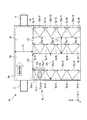
- FIG. 9 is a cross-sectional view illustrating an example of the configuration of the object operating device 1a according to the first modification of the present embodiment.
- the change in the fluid pressure of the liquid W in the chamber 3 mainly occurs at the fluid pressure change portion R, which is a portion sandwiched between the cell / water inlet 2 and the cell / water recovery port 4 in the chamber 3a.
- the inlet 72a-1 to 72a-4, the inlet 72a-5 to 72a-8, and the inlet 72a-9 to 72a-12 of the isolation part 7a are surfaces on the hydraulic pressure change portion R. Not done.
- the portion to be stored in the separating portion 7a does not face in the direction in which the hydraulic pressure is generated.
- the interval L2 is wider than the interval L1.
- the interval L3 is narrower than the interval L1.
- the interval L4 is wider than the interval L1.
- the interval L5 is narrower than the interval L1.
- the cell C1 is sandwiched between the first wall 70a-1 of the isolation part 7a-1 and the second wall 71a-2 of the isolation part 7a-2 and is held by the electric field EC.
- the cell C1 isolated in the isolation part 7a may be held by the electric field EC generated at the position of the interval L2.
- the cell C1 is separated from the wall formed by the isolation parts 7a-1 to 7a-5 and the isolation part 7a. -6 to be sandwiched between the wall formed by the isolation part 7a-10.
- the cell C1 isolated in the isolation part 7a may be held by the electric field EC generated at the position of the interval L3.
- the cell C1 isolated in the isolation part 7a is held by the electric field EC generated at the position of the interval L3, the cell C1 is divided into a wall formed by the isolation part 7a-6 to the isolation part 7a-10, and the isolation part 7a. -11 to the wall formed by the isolation part 7a-15.
- the isolation part in the above embodiment, in FIG. 1 and FIG. 2, in the cells arranged in the isolation part, the influence of the fluid pressure caused by the liquid that is input from the cell / water input port and recovered from the cell / water recovery port 4 is suppressed. Therefore, the isolation part is provided along the Y axis, and the wall of the isolation part is arranged along the Y axis. Furthermore, the distance between the walls of the isolation part is formed so as to extend along the X-axis direction. That is, on the XY plane, the walls of the isolation part were V-shaped. The shape of the walls of the isolation part is not limited to the above V shape.
- the shape of the walls of the isolation part can be changed as long as the shape can suppress the influence of the fluid pressure on the cells.
- a case where the shape of the walls of the isolation part is changed from the above V shape will be described with reference to FIGS. 10 to 12.
- FIG. 10 is a diagram illustrating an example of a cross-sectional view of the shape of the walls of the isolation portion 7b according to the present modification.
- the isolation unit 7b includes isolation units 7b-i (i is a natural number).
- the distance between the first wall 70b of the separating part 7b-i and the second wall 71b of the separating part 7b-i + 1 is formed so as to extend along the X-axis direction.
- the first wall 70b is not parallel to the X axis
- the second wall 71b is parallel to the X axis.
- the first wall 70b and the second wall 71b have a crossing point. That is, the shape of the walls of the isolation part 7b is serrated.
- the inlet 72b is formed by the first wall 70b and the second wall 71b.
- FIG. 11 is a diagram illustrating an example of a cross-sectional view of the shape of the walls of the isolation portion 7c according to the present modification.
- the isolation unit 7c includes an isolation unit 7c-i (i is a natural number).
- the distance between the first wall 70c of the isolation part 7c-i and the second wall 71c of the isolation part 7c-i + 1 is formed so as to extend along the X-axis direction.
- the first wall 70c and the second wall 71c are not parallel to the X axis.
- the first wall 70c and the second wall 71c do not have a crossing point.
- the inlet 72c is formed by the first wall 70c and the second wall 71c.
- FIG. 12 is a diagram illustrating an example of a cross-sectional view of the shape of the walls of the isolation portion 7d according to the present modification.
- the isolation unit 7d includes an isolation unit 7d-i (i is a natural number).
- the distance between the first wall 70d of the isolation part 7d-i and the second wall 71d of the isolation part 7d-i + 1 is formed so as not to change along the X-axis direction. That is, the first wall 70d and the second wall 71d are parallel.
- the first wall 70d and the second wall 71d do not have a crossing point.
- the inlet 72d is formed by the first wall 70d and the second wall 71d.
- FIG. 13 is a diagram illustrating an example of a cross-sectional view of the shape of the walls of the isolation portion 7e according to the present modification.
- the isolation unit 7e includes an isolation unit 7e-i (i is a natural number).
- the first wall 70e-i of the isolation part 7e-i is parallel to the Y axis.
- the isolator 7e-i has an outlet 73e-i in addition to the inlet 72-i.
- the cell C1 enters the isolation part 7e-i from the inlet 72e-i and is stored in the isolation part 7e-i.
- the electric field E generated by irradiating the isolation part 7e-i with the light EL blocks the inlet 72-i and the outlet 73e-i and surrounds the cell C1 stored in the isolation part 7e-i.
- the cell C1 moves out of the isolation part 7e-i from the outlet 73e-i.
- the inlet 72-i may function as an outlet, and the outlet 73e-i may function as an inlet.
- the inlet 72-i may also serve as an outlet, and the outlet 73e-i may also serve as an inlet.
- FIG. 14 is a diagram illustrating an example of a cross-sectional view of the shape of the walls of the isolation portion 7f of the present embodiment.
- the isolating unit 7f includes an isolating unit 7f-i (i is a natural number).
- the distance between the first wall 70f of the isolation part 7f-i and the second wall 71f of the isolation part 7f-i + 1 is formed so as to extend along the X-axis direction.
- the first wall 70f and the second wall 71f form a curved concave surface, and the shape of the walls of the isolation portion 7f is U-shaped.
- the inlet 72f is formed by the first wall 70f and the second wall 71f.
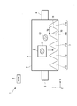
- FIG. 15 is a cross-sectional view showing an example of the configuration of the object operating device 1g of the present embodiment.
- the object operating device 1g does not include the isolation part 7a included in the object operating device 1a of FIG.
- the first wall 70g and the second wall 71g which are part of the inner wall of the chamber 3g, function as an isolation part that isolates the cell C1.
- the cell C1 is moved to the isolation portion R1.
- the isolation portion R1 is a portion on the negative side of the X axis with respect to the hydraulic pressure change portion R, which is a portion sandwiched between the cell / water inlet 2 and the cell / water recovery port 4 in the chamber 3g. It is.
- the cell C1 enters the isolation part R1 from the inlet 72g and is stored in the isolation part R1.
- the inlet 72g is formed in a cross section parallel to the Y axis on the negative side of the X axis from the hydraulic pressure change portion R in the chamber 3g.
- the electric field ECg is generated in the vicinity of the entrance 72g, thereby holding the cell C1 stored in the isolation portion R1.
- the electric field generated by the irradiation of light around the object is used for the operation of the object of the object moving unit, but the present invention is not limited to this.
- An electrode array may be used for the operation of the object of the object moving unit.
- the electrode array can be individually turned on or off by an electrical signal.
- an electric field may be generated by turning on the electrodes around the object arranged in the isolating unit, and the object may be moved and stored in the isolating unit.
- an electric field generated by light irradiation around the target object and an electric field generated by the electrode array may be used in combination.
- the holding mechanism for holding the object to be isolated by the isolation part holds the object by an electric field generated by light irradiation around the object arranged at the isolation part.
- the present invention is not limited to this.
- An electric field generated by the electrode array may be used for the holding mechanism for holding the object to be isolated by the isolation part.
- the holding mechanism for holding the object to be isolated by the isolation part is not limited to an electric field, and a mechanical shutter may be used.
- the target moving unit includes an AC voltage source.
- the present invention is not limited to this.
- the target moving unit may include a DC voltage source instead of the AC voltage source.
- the holding mechanism has been described with respect to the case where the object stored in the isolation unit is held by an electric field, but is not limited thereto.
- the object In the chamber, the object may be held by an electric field without being stored in the isolator. That is, the holding mechanism may hold the object stored in the chamber 3 regardless of the flow of the liquid when the liquid in the chamber 3 flows without the object being stored in the isolation part.
- the strength of the electric field used when the object is not stored in the isolator may be adjusted according to the magnitude of the change in hydraulic pressure in the chamber.
- the program for performing each process of the control part 5 of the target object operating device 1 in the embodiment of the present invention is recorded on a computer-readable recording medium, and the program recorded on the recording medium is stored in the computer system.
- the various processes described above may be performed by reading and executing.
- the “computer system” referred to here may include an OS and hardware such as peripheral devices. Further, the “computer system” includes a homepage providing environment (or display environment) if a WWW system is used.
- the “computer-readable recording medium” means a flexible disk, a magneto-optical disk, a ROM, a writable nonvolatile memory such as a flash memory, a portable medium such as a CD-ROM, a hard disk built in a computer system, etc. This is a storage device.
- the “computer-readable recording medium” refers to a volatile memory (for example, DRAM (Dynamic) in a computer system serving as a server or a client when a program is transmitted via a network such as the Internet or a communication line such as a telephone line. Random Access Memory)), etc. that hold a program for a certain period of time.
- the program may be transmitted from a computer system storing the program in a storage device or the like to another computer system via a transmission medium or by a transmission wave in the transmission medium.
- the “transmission medium” for transmitting the program refers to a medium having a function of transmitting information, such as a network (communication network) such as the Internet or a communication line (communication line) such as a telephone line.
- the program may be for realizing a part of the functions described above. Furthermore, what can implement
- First wall 71, 71a, 71b, 71c, 71d, 71f, 71g ...
- Second wall 72, 72a, 72b, 72c, 72d, 72f, 72g ... inlet, 73d ... exit, W ... liquid, VE ... light irradiation region VE, E, EC, ECg ... electric field, EL ... light EL
Landscapes
- Engineering & Computer Science (AREA)
- Chemical & Material Sciences (AREA)
- Health & Medical Sciences (AREA)
- Physics & Mathematics (AREA)
- Life Sciences & Earth Sciences (AREA)
- Organic Chemistry (AREA)
- Bioinformatics & Cheminformatics (AREA)
- Wood Science & Technology (AREA)
- Zoology (AREA)
- General Health & Medical Sciences (AREA)
- Analytical Chemistry (AREA)
- General Physics & Mathematics (AREA)
- Multimedia (AREA)
- Genetics & Genomics (AREA)
- Biotechnology (AREA)
- Sustainable Development (AREA)
- Microbiology (AREA)
- General Engineering & Computer Science (AREA)
- Biomedical Technology (AREA)
- Biochemistry (AREA)
- Computer Vision & Pattern Recognition (AREA)
- Optics & Photonics (AREA)
- Clinical Laboratory Science (AREA)
- Theoretical Computer Science (AREA)
- Radiology & Medical Imaging (AREA)
- Nuclear Medicine, Radiotherapy & Molecular Imaging (AREA)
- Medical Informatics (AREA)
- Quality & Reliability (AREA)
- Hematology (AREA)
- Chemical Kinetics & Catalysis (AREA)
- Computer Hardware Design (AREA)
- Electromagnetism (AREA)
- Cell Biology (AREA)
- Dispersion Chemistry (AREA)
- Apparatus Associated With Microorganisms And Enzymes (AREA)
Abstract
Description
チャンバ内の液体が流れたときに、液体の流れによらず移動させることにおいて移動させられた対象物を保持することとを有する、対象物操作方法である。
チャンバ内の液体が流れたときに、液体の流れによらず選択することにおいて選択された対象物を保持することとを有する、対象物操作方法である。
以下、図面を参照して、本発明の第1実施形態について説明する。図1は、本実施形態による対象物操作装置1の構成の一例を示す斜視図である。また、図2は、本実施形態による対象物操作装置1の構成の一例を示す断面図である。対象物操作装置1は、対象物を操作する装置である。
以下の説明では、対象物が細胞である場合について説明するが、対象物は粒子であってもよい。
細胞・水投入口2は、チャンバ3に接続される。細胞・水投入口2は、液体Wをチャンバ3に供給する供給部である。つまり、チャンバ3は、液体Wをチャンバ3に供給する供給部を有する。液体Wとは、例えば、水や緩衝液である。本実施形態では、液体Wは、一例として、緩衝液である。この緩衝液の電気伝導率は、例えば、10mS/mである。
また、細胞・水投入口2は、細胞をチャンバ3に供給する。
なお、本実施形態では、選別対象の細胞と、選別対象でない細胞とがそれぞれ1個である場合について説明するが、チャンバ3に配置される細胞の数はこれに限らない。チャンバ3に配置される細胞の数は2個以上であってよく、対象物操作装置1は、チャンバ3に配置される細胞のうち複数の細胞を同時に選別対象として操作することができる。
制御部5は、対象物操作装置1を制御する。制御部5は、細胞操作部6、細胞・水投入口2、細胞・水回収口4の制御により、対象物操作装置1を制御する。
このように、対象物操作装置1では、対象物を囲う壁には第1壁70と第2壁71とを有し、第1壁70と第2壁71は入口72を形成し、対象移動部(細胞操作部6)により移動させられる対象物は、入口72を通って第1壁70と第2壁71とに囲まれる。ここで隔離部7の第1壁70の壁面と第2壁71の壁面とは非平行である。ここで第1壁70の壁面と第2壁71の壁面とは向かい合っている。
光照射部9は、細胞操作部6による操作のための電場Eを発生するための光ELを細胞操作部6に照射する。
図3は、本実施形態の細胞操作部6が細胞C1を移動させる方法の一例を示す図である。
細胞操作部6は、光電子ピンセット(OET:Optoelectronic tweezer)を用いて細胞を移動させる。ここでOETは、光ビームを用いて第1電極60の第2電極61に対する電位を変化させ、この電位の変化により発生した不均一な電場による誘電泳動(DEP:Dielectrophoresis)により、細胞を移動させる技術である。DEPは、細胞生物学及びコロイド科学の分野において細胞を操作するための技術として知られる。DEPでは、細胞を不均一な電場にさらすことにより、細胞の動きを制御する。
以下では、第1電極60と第2電極61との間に発生する電場の発生の方式について説明する。
第2電極61は、透明電極である。ここで透明電極とは、例えば、ITOガラスである。
このように第2電極61は透明電極であり、透明電極を通過した光ELが光照射領域VEに照射される。
本実施形態では、AC電圧源62は、一例として、100kHzの周波数で約10Vppのピークピーク電圧のAC電圧を、第1電極60及び第2電極61に印加する。
図3に示す例では、細胞C1が正のDEP力により光の壁に引きつけられている。
ここで図4を参照し、細胞操作部6が負のDEP力を用いる場合の一例について説明する。
図5は、本実施形態のマイクロビジョンをベースとする自動光操作システムSの一例を示す図である。自動光操作システムSでは、マイクロビジョンをベースとするパターン認識と、微細粒子を処理するOET装置D4とが一体化されている。自動光操作システムSは、ランダムに分散した細胞の位置及びサイズを自動的に認識し、選択対象の細胞C1を捕捉して輸送するための直接イメージパターンを生成して、細胞C1の移動経路を計算する。自動光操作システムSでは、多数の細胞を並行して捕捉し、輸送し、かつ集合させるというクローズループ制御が可能である。
細胞の動きは、光源D2から生成されてDMDマイクロディスプレイD1から反射された光ELを、対物レンズD3を介してOET装置D4上に投影することにより制御される。上記光学パターンは、イメージ分析とパターン認識アルゴリズムとを組み合わせた顕微鏡イメージング手段によって記録された細胞の位置及び特性に応じて生成される。上記イメージは、レンズD5を通してCCDイメージャD6に集められ、上記データは、生成される光のパターンを制御するように処理される。上記顕微鏡イメージは、イメージ分析回路および/またはルーチンS1内において分析される。次いで、上記イメージデータは、パターン認識回路および/またはルーチンS2を用いて処理される。実際のパターンの認識は、その用途の所望の目的に関して実行され、そこから後のパターンが、パターン生成回路および/またはルーチンS3によって生成される。上記パターンは、プログラム可能なDMDマイクロディスプレイD1の動作を制御するように、DMD回路および/またはルーチンS4によって変換される。
上述のイメージ分析回路および/またはルーチンS1、パターン認識回路および/またはルーチンS2、パターン生成回路および/またはルーチンS3、及びDMD回路および/またはルーチンS4は、図1及び図2における制御部5が備える構成または機能として実現される。
また、DMDマイクロディスプレイD1と、光源D2と、対物レンズD3とは、対象物操作装置1の光照射部9として機能する。光源D2は、一例としてハロゲンランプであり、プログラム可能なDMDマイクロディスプレイD1をを照明する。
レンズD5及びCCDイメージャD6には、例えば倒立顕微鏡を用いる。
図6は、本実施形態の細胞操作の処理の流れの一例を示す図である。
対象物操作装置1は、細胞操作部6に導入された細胞を、カメラ8により観察する(ステップS102)。
選択対象となる細胞に、細胞操作部6への導入の前に予めマーキングをしてもよい。ここで細胞へのマーキングは、例えば、細胞に蛍光物質を組み込み、細胞から特定の波長が発せられるようにすることにより行われてよい。
また、細胞の選択には、画像分析が用いられてもよい。例えば、画像分析を用いた細胞の選択には、選択対象となる細胞の所定の特徴量に基づいて、カメラ8による観察画像から選択対象となる細胞が選択されてもよい。
また、選択対象となる細胞は、対象物操作装置1の使用者によってカメラ8による観察画像が観察されて選択されてもよい。この場合、制御部5は対象物操作装置1の使用者による細胞を選択する操作を受け付ける。
なお、複数の種類の細胞のなかから、特定の種類の細胞が選択されてもよい。
細胞操作部6は、選択した細胞の細胞操作部6における座標により示される位置の周囲に光ELを照射し、光ELが照射された位置の周囲に電場Eを発生させる(ステップS105)。
細胞操作部6は、発生させた電場Eを移動させることにより、電場Eに囲まれた細胞C1を移動させる(S106)。つまり、細胞操作部6は、液体と対象物とを収容するチャンバ3内に収容される対象物をチャンバ3内で移動させる。
図7は、本実施形態の細胞操作部6が電場Eに囲まれた細胞C1を移動させる処理の一例を示す図である。細胞操作部6は、選択した細胞の細胞操作部6における座標により示される位置の周囲に光ELを照射し、光ELが照射された位置の周囲に電場Eを発生させる。ここで細胞操作部6における座標とは、図7のX座標とY座標とによって示される第1電極60上あるいは第2電極61上における座標である。
選択対象である細胞C1は、細胞操作部6が発生させた電場Eにより囲まれている。細胞操作部6は、電場Eを移動させることにより細胞C1を移動させる。
細胞操作部6は、細胞C1を隔離部7に配置させる(ステップS107)。
対象物操作装置1は、選択対象の細胞毎に細胞を隔離部7に配置する処理を終了する(ステップS108)。
対象物操作装置1は、細胞・水投入口2からチャンバ3に液体Wを流入させ隔離部7に格納されなかった細胞C2を、細胞・水回収口4から排出する(ステップS110)。
図8は、本実施形態の細胞の保持機構の一例を示す図である。図8に示す例では、細胞C1が隔離部7-2の第1壁70-2と隔離部7-3の第2壁71-3との間の空間に隔離されている。ここで隔離部7-2と隔離部7-3とに光ELが照射されることにより、電場ECが発生している。電場ECは、第1壁70-2と第2壁71-3とともに、細胞C1を囲う。つまり、対象物操作装置1では、保持機構に保持される対象物の少なくとも一部を壁で囲った状態で、保持機構により対象物を保持する。
このように、チャンバ3に接続された細胞・水回収口4は、隔離部7に格納されなかった細胞C2をチャンバ3内の液圧の変化により排出する排出部として機能する。つまり、チャンバ3は、チャンバ3内の液体Wを排出する排出部を有する。
ここで電場ECは、チャンバ3内に収容される細胞C1の周囲への光ELの照射により発生する。つまり、対象移動部(細胞操作部6)による操作のための電場Eの発生方法と、対象物操作装置1の保持機構による保持のための電場ECの発生方法とは同じである。したがって、保持機構の電場の発生方法と、前記対象移動部の電場の発生方法とは同じである。
制御部5は、カメラ8による観察画像を用いて、隔離部7に格納された細胞C1が所望の細胞であるか否かを判定する(ステップS111)。
隔離部7に格納された細胞C1が所望の細胞であるか否かの判定は、対象物操作装置1の使用者によってカメラ8による観察画像が観察されて、隔離部7に格納された細胞C1が所望の細胞であることを確認する操作に基づいて行われてよい。
隔離部7に格納された細胞C1が所望の細胞であるか否かの判定は、画像分析に基づいて行われてよい。例えば、カメラ8による撮像された観察画像に含まれる細胞C1の細胞画像が分析されることにより、隔離部7に格納された細胞C1が所望の細胞であるか否かの判定が行われてよい。
一方、制御部5は、隔離部7に格納された細胞C1が所望の細胞でないと判定する場合(ステップS111:NO)、所望の細胞でない細胞C1の格納を解除する(ステップS112)。ここで所望の細胞でない細胞C1の格納を解除するとは、細胞C1が配置された隔離部7への光ELの照射を中止し、第1壁70-2と第2壁71-3とともに細胞C1を囲っていた電場ECを消去することである。
この構成により、本実施形態の対象物操作装置1では、チャンバ内の液圧の変化によらず選別対象の対象物を保持できるため、選別対象の対象物を選別することができる。
この構成により、本実施形態の対象物操作装置1では、隔離部7に対象物を保持するための部材を予め備える必要がないため、隔離部7に対象物を保持するための部材を予め備える場合に比べて広い空間を確保することができるため、対象物の隔離部7への格納、及び対象物の隔離部7からの取り出しが、隔離部7に対象物を保持するための部材を予め備える場合に比べて容易である。
この構成により、本実施形態の対象物操作装置1では、仮想電極パターンを光学的に形成し電場Eを発生させることができるため、固定された電極が発生させる電場を用いる場合などに比べて精密に対象物を移動させることができる。
この構成により、本実施形態の対象物操作装置1では、保持機構による保持のための電場ECの発生させるために、対象移動部(細胞操作部6)による操作のための電場Eの発生方法を用いることができるため、保持機構による保持のための電場ECを別途発生させる必要がない。
この構成により、本実施形態の対象物操作装置1では、電場(電場E、及び電場EC)を発生させるために光ELを用いることができるため、簡便に電場(電場E、及び電場EC)を発生させることができる。
この構成により、本実施形態の対象物操作装置1では、対象物の周囲に光ELを照射することができるため、対象物の周囲に光ELを照射する装置を別途設ける必要がない。
この構成により、本実施形態の対象物操作装置1では、仮想電極パターンを光学的に形成し光照射領域VEと第2電極61との間に電場Eを発生させることができるため、第1電極60と第2電極61との間に配置された対象物を、固定された電極が発生させる電場を用いる場合などに比べて精密に対象物を移動させることができる。
この構成により、本実施形態の対象物操作装置1では、第1電極60の外側から光ELを光照射領域VEに照射することができるため、光ELを照射する光照射部9の位置の選択の幅が広がる。
この構成により、本実施形態の対象物操作装置1では、保持機構に保持される対象物の少なくとも一部を囲う壁を用いて対象物を保持することができるため、電場ECのみを用いて対象物を保持する場合に比べて、より安定して対象物を保持することができる。
この構成により、本実施形態の対象物操作装置1では、第1壁70と第2壁71とにより形成される入口から対象物を第1壁70と第2壁71とにより囲まれる領域に進入させることができるため、進入した対象物を第1壁70と第2壁71とにより収容することができる。
この構成により、本実施形態の対象物操作装置1では、保持機構により保持された対象物は、第1壁70の壁面と第2壁71の壁面とが平行である場合に比べてチャンバ3内の液圧の変化の影響を受けにくいため、対象物を第1壁70の壁面と第2壁71の壁面とが平行である場合に比べてより安定に保持することができる。
この構成により、本実施形態の対象物操作装置1では、保持機構が保持する対象物を除く対象物をチャンバ3の外へ液圧の変化により排出することができるため、選択対象の対象物をチャンバ3内に残すことができる。
この構成により、本実施形態の対象物操作装置1では、液体Wをチャンバ3に供給することができるため、チャンバ3内の液圧を変化させることができる。
この構成により、本実施形態の対象物操作装置1では、細胞を操作対象とすることができるため、所望の細胞を選択することができる。
上記の実施形態では、チャンバ内の液体の液圧の変化が発生する部分に、隔離部の入口が面している場合の一例について説明した。本変形例では、チャンバ内の液体の液圧の変化が発生する部分に、隔離部の入口が面していない場合の一例について説明する。
本変形例の対象物操作装置を対象物操作装置1aという。
このように、対象物操作装置1aでは、図9のように隔離部7aと、液体Wの投入口である細胞・水投入口2と、液体Wの回収口である細胞・水回収口4とが配置され、液圧が発生する方向に隔離部7aで格納する部分が面していない。
同様に、間隔L3位置に発生する電場ECにより、隔離部7aに隔離された細胞C1を保持してもよい。間隔L3位置に発生する電場ECにより、隔離部7aに隔離された細胞C1を保持する場合、細胞C1は、隔離部7a-6~隔離部7a-10とにより形成される壁と、隔離部7a-11~隔離部7a-15とにより形成される壁との間に挟まれる。
上記の実施形態では、図1及び図2では、隔離部にに配置された細胞では、細胞・水投入口から投入され細胞・水回収口4から回収される液体に伴う液圧の影響を抑制するため、Y軸に沿って隔離部が設けられ、隔離部の壁がY軸に沿って配置されていた。さらに、隔離部の壁同士の距離はX軸方向に沿って広がるように形成されていた。つまり、XY平面では、隔離部の壁同士はV字形状であった。
隔離部の壁同士の形状は上記のV字形状に限らない。隔離部の壁同士の形状は、細胞への液圧の影響を抑制できる形状であれば変更することが可能である。本実施形態の第2変形例では、図10~図12を参照し、隔離部の壁同士の形状が上記のV字形状から変更される場合について説明する。
隔離部7b-iの第1壁70bと隔離部7b-i+1の第2壁71bとの距離はX軸方向に沿って広がるように形成される。ここで第1壁70bはX軸に平行ではなく、第2壁71bはX軸に平行である。また、第1壁70bと第2壁71bとは交差する点を有する。つまり、隔離部7bの壁同士の形状は鋸歯状である。入口72bは、第1壁70bと第2壁71bとにより形成される。
図11は、本変形例の隔離部7cの壁同士の形状の断面図の一例を示す図である。隔離部7cは、隔離部7c-i(iは自然数)を備える。
隔離部7c-iの第1壁70cと隔離部7c-i+1の第2壁71cとの距離はX軸方向に沿って広がるように形成される。ここで第1壁70c及び第2壁71cはX軸に平行ではない。第1壁70cと第2壁71cとは交差する点を有さない。入口72cは、第1壁70cと第2壁71cとにより形成される。
図12は、本変形例の隔離部7dの壁同士の形状の断面図の一例を示す図である。隔離部7dは、隔離部7d-i(iは自然数)を備える。
隔離部7d-iの第1壁70dと隔離部7d-i+1の第2壁71dとの距離はX軸方向に沿って変わらないように形成される。つまり、第1壁70dと第2壁71dとは平行である。第1壁70dと第2壁71dとは交差する点を有さない。入口72dは、第1壁70dと第2壁71dとにより形成される。
図13は、本変形例の隔離部7eの壁同士の形状の断面図の一例を示す図である。隔離部7eは、隔離部7e-i(iは自然数)を備える。
隔離部7e-iの第1壁70e-iは、Y軸と平行である。隔離部7e-iは、入口72-iに加え、さらに出口73e-iを有する。細胞C1は、入口72e-iから隔離部7e-iに進入し、隔離部7e-iに格納される。隔離部7e-iに光ELが照射されることにより発生する電場Eは、入口72-i及び出口73e-iを塞ぎ、隔離部7e-iに格納された細胞C1を囲う。細胞C1を隔離部7e-iから取り出す場合、細胞C1は出口73e-iから隔離部7e-iの外へ移動する。
なお、入口72-iが出口として機能し、出口73e-iが入口として機能してもよい。また、入口72-iは出口を兼ねてもよく、出口73e-iは入口を兼ねてもよい。
第2実施形態では、隔離部の壁同士の形状について、第1実施形態及び第2変形例において説明した以外の例について説明する。
図14は、本実施形態の隔離部7fの壁同士の形状の断面図の一例を示す図である。隔離部7fは、隔離部7f-i(iは自然数)を備える。
隔離部7f-iの第1壁70fと隔離部7f-i+1の第2壁71fとの距離はX軸方向に沿って広がるように形成される。ここで第1壁70fと第2壁71fとは、湾曲した凹面を形成し、隔離部7fの壁同士の形状はU字形状である。入口72fは、第1壁70fと第2壁71fとにより形成される。
第3実施形態では、第1実施形態の第1変形例において説明したチャンバ内の液体の液圧の変化が発生する部分に、隔離部の入口が面していない場合の他の例について説明する。
本実施形態の対象物操作装置を対象物操作装置1gという。
対象物操作装置1gは、図9の対象物操作装置1aが備えていた隔離部7aを備えていない。対象物操作装置1gでは、チャンバ3gの一部の内壁である第1壁70g及び第2壁71gが、細胞C1を隔離する隔離部として機能する。
対象物操作装置1gでは、入口72gの付近に電場ECgを発生させることにより、隔離部分R1に格納された細胞C1を保持する。
対象移動部の対象物の操作には、対象物の周囲への光の照射により発生する電場と、電極アレイが発生させる電場とを組み合わせて用いてもよい。
また、法令で許容される限りにおいて、上述の各実施形態及び変形例で引用した装置などに関する全ての公開公報及び米国特許の開示を援用して本文の記載の一部とする。
Claims (16)
- 液体と対象物とを収容するチャンバと、
前記チャンバ内に収容される対象物を前記チャンバ内で移動させる対象移動部と、
前記チャンバ内の液体が流れたときに、前記液体の流れによらず前記対象物を保持するための保持機構とを備える、対象物操作装置。 - 前記保持機構は、前記対象物の周囲に発生させられる電場により、前記対象物を保持する、請求項1に記載の対象物操作装置。
- 前記対象移動部は、前記対象物の周囲に発生させられる電場により、前記対象物を移動させる、請求項1または2に記載の対象物操作装置。
- 前記保持機構の電場の発生方法と、前記対象移動部の電場の発生方法とは同じである、請求項2または3に記載の対象物操作装置。
- 前記対象物の周囲に光照射することで、電場を発生させる、請求項2から4のいずれか一項に記載の対象物操作装置。
- 前記対象物の周囲に光を照射する光照射部を備える請求項5に記載の対象物操作装置。
- 前記対象移動部は電圧が印加される第1電極と第2電極とを備え、
前記光照射部により照射された光照射領域と第2電極との間に電場が発生する、請求項6に記載の対象物操作装置。 - 前記第1電極は透明電極であり、前記透明電極を通過した光が前記光照射領域に照射される、請求項7に記載の対象物操作装置。
- 前記保持機構に保持される前記対象物の少なくとも一部を壁で囲った状態で、前記保持機構により前記対象物を保持する、請求項1から8のいずれか一項に記載の対象物操作装置。
- 前記対象物を囲う壁には第1壁と第2壁とを有し、前記第1壁と前記第2壁は入口を形成し、前記対象移動部により移動させられる前記対象物は、前記入口を通って前記第1壁と前記第2壁とに囲まれる、請求項9に記載の対象物操作装置。
- 前記第1壁の壁面と前記第2壁の壁面とが非平行である請求項10に記載の対象物操作装置。
- 前記チャンバは、前記チャンバ内の液体を排出する排出部を有する請求項1~11のいずれか一項に記載の対象物操作装置。
- 前記チャンバは、液体を前記チャンバに供給する供給部を有する請求項1~12のいずれか一項に記載の対象物操作装置。
- 前記対象物とは、細胞である請求項1~13のいずれか一項に記載の対象物操作装置。
- 液体と対象物とを収容するチャンバ内に収容される対象物を前記チャンバ内で移動させることと、
前記チャンバ内の液体が流れたときに、前記液体の流れによらず前記移動させることにおいて移動させられた前記対象物を保持することとを有する、対象物操作方法。 - 液体と対象物とを収容するチャンバ内に収容される対象物を選択することと、
前記チャンバ内の液体が流れたときに、前記液体の流れによらず前記選択することにおいて選択された前記対象物を保持することとを有する、対象物操作方法。
Priority Applications (3)
| Application Number | Priority Date | Filing Date | Title |
|---|---|---|---|
| EP18797890.3A EP3623461A4 (en) | 2017-05-12 | 2018-03-13 | OBJECT MANIPULATION DEVICE AND OBJECT MANIPULATION METHOD |
| JP2019517474A JPWO2018207454A1 (ja) | 2017-05-12 | 2018-03-13 | 対象物操作装置、及び対象物操作方法 |
| US16/680,332 US20200159002A1 (en) | 2017-05-12 | 2019-11-11 | Device for manipulating an object and method for manipulating an object |
Applications Claiming Priority (2)
| Application Number | Priority Date | Filing Date | Title |
|---|---|---|---|
| US201762505141P | 2017-05-12 | 2017-05-12 | |
| US62/505,141 | 2017-05-12 |
Related Child Applications (1)
| Application Number | Title | Priority Date | Filing Date |
|---|---|---|---|
| US16/680,332 Continuation US20200159002A1 (en) | 2017-05-12 | 2019-11-11 | Device for manipulating an object and method for manipulating an object |
Publications (1)
| Publication Number | Publication Date |
|---|---|
| WO2018207454A1 true WO2018207454A1 (ja) | 2018-11-15 |
Family
ID=64104592
Family Applications (1)
| Application Number | Title | Priority Date | Filing Date |
|---|---|---|---|
| PCT/JP2018/009683 WO2018207454A1 (ja) | 2017-05-12 | 2018-03-13 | 対象物操作装置、及び対象物操作方法 |
Country Status (4)
| Country | Link |
|---|---|
| US (1) | US20200159002A1 (ja) |
| EP (1) | EP3623461A4 (ja) |
| JP (1) | JPWO2018207454A1 (ja) |
| WO (1) | WO2018207454A1 (ja) |
Families Citing this family (1)
| Publication number | Priority date | Publication date | Assignee | Title |
|---|---|---|---|---|
| WO2020091732A1 (en) * | 2018-10-29 | 2020-05-07 | Hewlett-Packard Development Company, L.P. | Rotation and flat-form imaging for microscopic objects |
Citations (5)
| Publication number | Priority date | Publication date | Assignee | Title |
|---|---|---|---|---|
| JP2007537729A (ja) * | 2004-04-12 | 2007-12-27 | ザ・レジェンツ・オブ・ザ・ユニバーシティ・オブ・カリフォルニア | 微粒子及び細胞の操作用の光電子ピンセット |
| WO2011149032A1 (ja) * | 2010-05-26 | 2011-12-01 | 東ソー株式会社 | 生体試料固定装置 |
| WO2016094308A1 (en) | 2014-12-08 | 2016-06-16 | Berkeley Lights, Inc. | Microfluidic device comprising lateral/vertical transistor structures and process of making and using same |
| WO2016141343A1 (en) * | 2015-03-04 | 2016-09-09 | Berkeley Lights, Inc. | Generation and selection of embryos in vitro |
| JP2017108738A (ja) * | 2015-12-15 | 2017-06-22 | 東ソー株式会社 | 細胞検出装置および細胞回収装置 |
Family Cites Families (3)
| Publication number | Priority date | Publication date | Assignee | Title |
|---|---|---|---|---|
| US9857333B2 (en) * | 2012-10-31 | 2018-01-02 | Berkeley Lights, Inc. | Pens for biological micro-objects |
| US20150166326A1 (en) * | 2013-12-18 | 2015-06-18 | Berkeley Lights, Inc. | Capturing Specific Nucleic Acid Materials From Individual Biological Cells In A Micro-Fluidic Device |
| AU2016252995B2 (en) * | 2015-04-22 | 2020-12-03 | Berkeley Lights, Inc. | Freezing and archiving cells on a microfluidic device |
-
2018
- 2018-03-13 JP JP2019517474A patent/JPWO2018207454A1/ja active Pending
- 2018-03-13 EP EP18797890.3A patent/EP3623461A4/en not_active Withdrawn
- 2018-03-13 WO PCT/JP2018/009683 patent/WO2018207454A1/ja active Application Filing
-
2019
- 2019-11-11 US US16/680,332 patent/US20200159002A1/en not_active Abandoned
Patent Citations (6)
| Publication number | Priority date | Publication date | Assignee | Title |
|---|---|---|---|---|
| JP2007537729A (ja) * | 2004-04-12 | 2007-12-27 | ザ・レジェンツ・オブ・ザ・ユニバーシティ・オブ・カリフォルニア | 微粒子及び細胞の操作用の光電子ピンセット |
| USRE44711E1 (en) | 2004-04-12 | 2014-01-21 | The Regents Of The University Of California | Optoelectronic tweezers for microparticle and cell manipulation |
| WO2011149032A1 (ja) * | 2010-05-26 | 2011-12-01 | 東ソー株式会社 | 生体試料固定装置 |
| WO2016094308A1 (en) | 2014-12-08 | 2016-06-16 | Berkeley Lights, Inc. | Microfluidic device comprising lateral/vertical transistor structures and process of making and using same |
| WO2016141343A1 (en) * | 2015-03-04 | 2016-09-09 | Berkeley Lights, Inc. | Generation and selection of embryos in vitro |
| JP2017108738A (ja) * | 2015-12-15 | 2017-06-22 | 東ソー株式会社 | 細胞検出装置および細胞回収装置 |
Non-Patent Citations (1)
| Title |
|---|
| See also references of EP3623461A4 * |
Also Published As
| Publication number | Publication date |
|---|---|
| EP3623461A4 (en) | 2021-01-20 |
| US20200159002A1 (en) | 2020-05-21 |
| EP3623461A1 (en) | 2020-03-18 |
| JPWO2018207454A1 (ja) | 2020-03-19 |
Similar Documents
| Publication | Publication Date | Title |
|---|---|---|
| JP2008533531A (ja) | 光学的操作システム | |
| JP2019537067A5 (ja) | ||
| EP1667500B1 (en) | Apparatus and method for fabricating, sorting, and integrating materials with holographic optical traps | |
| US20150083911A1 (en) | Method of Detecting Electrons, an Electron-Detector and an Inspection System | |
| US10241050B2 (en) | Systems and methods for camera-based image processing in microscopy instruments | |
| US8921765B2 (en) | System for manipulating and optically targeting micro objects | |
| US20050276456A1 (en) | Cell-operating device | |
| WO2018207454A1 (ja) | 対象物操作装置、及び対象物操作方法 | |
| JP6551149B2 (ja) | 微粒子捕捉方法及び光ピンセット装置 | |
| JP2013235271A (ja) | レーザー顕微解剖装置及び方法 | |
| KR20190124791A (ko) | 타겟 상에 입자들을 디포지션하기 위한 장비 및 방법 | |
| JP2007330201A (ja) | 細胞分取用マイクロチップ及び細胞分取方法 | |
| US10903042B2 (en) | Apparatus and method for inspecting a sample using a plurality of charged particle beams | |
| JP5977527B2 (ja) | 走査型観察装置 | |
| JP2020174598A (ja) | 粒子操作方法、粒子捕捉用チップ、粒子操作システム、及び粒子捕捉用チャンバ | |
| US11163143B2 (en) | Observation apparatus | |
| JP4505665B2 (ja) | 光による微粒子の操作方法及び操作装置 | |
| JP2019033688A (ja) | 光トラップ装置、サンプル分別装置、及び光をサンプルに照射して捕捉する方法 | |
| JPH0518887A (ja) | 微粒子の計測及び操作方法 | |
| JP4962749B2 (ja) | 光による微粒子操作装置 | |
| Chiou et al. | Microvison-activated automatic optical manipulator for microscopic particles [microvison read microvision] | |
| US20060077361A1 (en) | Means of removing particles from a membrane mask in a vacuum | |
| JP3644318B2 (ja) | 微細物体の操作装置および操作方法 | |
| JP6278707B2 (ja) | 光学装置 | |
| JP2005335020A (ja) | 微小物体加工装置 |
Legal Events
| Date | Code | Title | Description |
|---|---|---|---|
| 121 | Ep: the epo has been informed by wipo that ep was designated in this application |
Ref document number: 18797890 Country of ref document: EP Kind code of ref document: A1 |
|
| ENP | Entry into the national phase |
Ref document number: 2019517474 Country of ref document: JP Kind code of ref document: A |
|
| NENP | Non-entry into the national phase |
Ref country code: DE |
|
| WWE | Wipo information: entry into national phase |
Ref document number: 2018797890 Country of ref document: EP |
|
| ENP | Entry into the national phase |
Ref document number: 2018797890 Country of ref document: EP Effective date: 20191212 |