WO2017104184A1 - Dispositif de séparation gaz-liquide - Google Patents
Dispositif de séparation gaz-liquide Download PDFInfo
- Publication number
- WO2017104184A1 WO2017104184A1 PCT/JP2016/075523 JP2016075523W WO2017104184A1 WO 2017104184 A1 WO2017104184 A1 WO 2017104184A1 JP 2016075523 W JP2016075523 W JP 2016075523W WO 2017104184 A1 WO2017104184 A1 WO 2017104184A1
- Authority
- WO
- WIPO (PCT)
- Prior art keywords
- gas
- liquid
- pipe
- flow generating
- generating ribbon
- Prior art date
Links
- 239000007788 liquid Substances 0.000 title claims abstract description 194
- 238000000926 separation method Methods 0.000 title claims abstract description 48
- 239000012530 fluid Substances 0.000 claims abstract description 66
- XLYOFNOQVPJJNP-UHFFFAOYSA-N water Substances O XLYOFNOQVPJJNP-UHFFFAOYSA-N 0.000 claims description 18
- 238000003860 storage Methods 0.000 claims description 11
- 238000007599 discharging Methods 0.000 claims 2
- 238000009434 installation Methods 0.000 abstract description 5
- 230000005484 gravity Effects 0.000 description 10
- 238000002485 combustion reaction Methods 0.000 description 9
- 230000002093 peripheral effect Effects 0.000 description 7
- 230000000694 effects Effects 0.000 description 5
- 238000004519 manufacturing process Methods 0.000 description 5
- 238000012986 modification Methods 0.000 description 5
- 230000004048 modification Effects 0.000 description 5
- 238000011144 upstream manufacturing Methods 0.000 description 5
- 238000001816 cooling Methods 0.000 description 3
- 239000003054 catalyst Substances 0.000 description 2
- 238000005520 cutting process Methods 0.000 description 2
- 238000009795 derivation Methods 0.000 description 2
- 238000010586 diagram Methods 0.000 description 2
- 230000006698 induction Effects 0.000 description 2
- 238000002955 isolation Methods 0.000 description 2
- 238000000746 purification Methods 0.000 description 2
- 239000003507 refrigerant Substances 0.000 description 2
- 238000007792 addition Methods 0.000 description 1
- 230000015572 biosynthetic process Effects 0.000 description 1
- 238000004891 communication Methods 0.000 description 1
- 230000007423 decrease Effects 0.000 description 1
- 238000001914 filtration Methods 0.000 description 1
- 238000000034 method Methods 0.000 description 1
- 238000002156 mixing Methods 0.000 description 1
- 238000005057 refrigeration Methods 0.000 description 1
- 238000009423 ventilation Methods 0.000 description 1
Images


Classifications
-
- B—PERFORMING OPERATIONS; TRANSPORTING
- B01—PHYSICAL OR CHEMICAL PROCESSES OR APPARATUS IN GENERAL
- B01D—SEPARATION
- B01D45/00—Separating dispersed particles from gases or vapours by gravity, inertia, or centrifugal forces
- B01D45/12—Separating dispersed particles from gases or vapours by gravity, inertia, or centrifugal forces by centrifugal forces
- B01D45/16—Separating dispersed particles from gases or vapours by gravity, inertia, or centrifugal forces by centrifugal forces generated by the winding course of the gas stream, the centrifugal forces being generated solely or partly by mechanical means, e.g. fixed swirl vanes
-
- B—PERFORMING OPERATIONS; TRANSPORTING
- B01—PHYSICAL OR CHEMICAL PROCESSES OR APPARATUS IN GENERAL
- B01D—SEPARATION
- B01D45/00—Separating dispersed particles from gases or vapours by gravity, inertia, or centrifugal forces
- B01D45/12—Separating dispersed particles from gases or vapours by gravity, inertia, or centrifugal forces by centrifugal forces
-
- B—PERFORMING OPERATIONS; TRANSPORTING
- B04—CENTRIFUGAL APPARATUS OR MACHINES FOR CARRYING-OUT PHYSICAL OR CHEMICAL PROCESSES
- B04C—APPARATUS USING FREE VORTEX FLOW, e.g. CYCLONES
- B04C3/00—Apparatus in which the axial direction of the vortex flow following a screw-thread type line remains unchanged ; Devices in which one of the two discharge ducts returns centrally through the vortex chamber, a reverse-flow vortex being prevented by bulkheads in the central discharge duct
- B04C3/02—Apparatus in which the axial direction of the vortex flow following a screw-thread type line remains unchanged ; Devices in which one of the two discharge ducts returns centrally through the vortex chamber, a reverse-flow vortex being prevented by bulkheads in the central discharge duct with heating or cooling, e.g. quenching, means
-
- B—PERFORMING OPERATIONS; TRANSPORTING
- B04—CENTRIFUGAL APPARATUS OR MACHINES FOR CARRYING-OUT PHYSICAL OR CHEMICAL PROCESSES
- B04C—APPARATUS USING FREE VORTEX FLOW, e.g. CYCLONES
- B04C3/00—Apparatus in which the axial direction of the vortex flow following a screw-thread type line remains unchanged ; Devices in which one of the two discharge ducts returns centrally through the vortex chamber, a reverse-flow vortex being prevented by bulkheads in the central discharge duct
- B04C3/06—Construction of inlets or outlets to the vortex chamber
-
- F—MECHANICAL ENGINEERING; LIGHTING; HEATING; WEAPONS; BLASTING
- F02—COMBUSTION ENGINES; HOT-GAS OR COMBUSTION-PRODUCT ENGINE PLANTS
- F02M—SUPPLYING COMBUSTION ENGINES IN GENERAL WITH COMBUSTIBLE MIXTURES OR CONSTITUENTS THEREOF
- F02M26/00—Engine-pertinent apparatus for adding exhaust gases to combustion-air, main fuel or fuel-air mixture, e.g. by exhaust gas recirculation [EGR] systems
- F02M26/50—Arrangements or methods for preventing or reducing deposits, corrosion or wear caused by impurities
-
- F—MECHANICAL ENGINEERING; LIGHTING; HEATING; WEAPONS; BLASTING
- F02—COMBUSTION ENGINES; HOT-GAS OR COMBUSTION-PRODUCT ENGINE PLANTS
- F02M—SUPPLYING COMBUSTION ENGINES IN GENERAL WITH COMBUSTIBLE MIXTURES OR CONSTITUENTS THEREOF
- F02M35/00—Combustion-air cleaners, air intakes, intake silencers, or induction systems specially adapted for, or arranged on, internal-combustion engines
- F02M35/02—Air cleaners
- F02M35/022—Air cleaners acting by gravity, by centrifugal, or by other inertial forces, e.g. with moistened walls
- F02M35/0223—Air cleaners acting by gravity, by centrifugal, or by other inertial forces, e.g. with moistened walls by centrifugal forces, e.g. cyclones
-
- F—MECHANICAL ENGINEERING; LIGHTING; HEATING; WEAPONS; BLASTING
- F02—COMBUSTION ENGINES; HOT-GAS OR COMBUSTION-PRODUCT ENGINE PLANTS
- F02M—SUPPLYING COMBUSTION ENGINES IN GENERAL WITH COMBUSTIBLE MIXTURES OR CONSTITUENTS THEREOF
- F02M35/00—Combustion-air cleaners, air intakes, intake silencers, or induction systems specially adapted for, or arranged on, internal-combustion engines
- F02M35/10—Air intakes; Induction systems
-
- B—PERFORMING OPERATIONS; TRANSPORTING
- B04—CENTRIFUGAL APPARATUS OR MACHINES FOR CARRYING-OUT PHYSICAL OR CHEMICAL PROCESSES
- B04C—APPARATUS USING FREE VORTEX FLOW, e.g. CYCLONES
- B04C3/00—Apparatus in which the axial direction of the vortex flow following a screw-thread type line remains unchanged ; Devices in which one of the two discharge ducts returns centrally through the vortex chamber, a reverse-flow vortex being prevented by bulkheads in the central discharge duct
- B04C2003/006—Construction of elements by which the vortex flow is generated or degenerated
-
- F—MECHANICAL ENGINEERING; LIGHTING; HEATING; WEAPONS; BLASTING
- F02—COMBUSTION ENGINES; HOT-GAS OR COMBUSTION-PRODUCT ENGINE PLANTS
- F02M—SUPPLYING COMBUSTION ENGINES IN GENERAL WITH COMBUSTIBLE MIXTURES OR CONSTITUENTS THEREOF
- F02M26/00—Engine-pertinent apparatus for adding exhaust gases to combustion-air, main fuel or fuel-air mixture, e.g. by exhaust gas recirculation [EGR] systems
- F02M26/02—EGR systems specially adapted for supercharged engines
- F02M26/04—EGR systems specially adapted for supercharged engines with a single turbocharger
- F02M26/05—High pressure loops, i.e. wherein recirculated exhaust gas is taken out from the exhaust system upstream of the turbine and reintroduced into the intake system downstream of the compressor
-
- F—MECHANICAL ENGINEERING; LIGHTING; HEATING; WEAPONS; BLASTING
- F02—COMBUSTION ENGINES; HOT-GAS OR COMBUSTION-PRODUCT ENGINE PLANTS
- F02M—SUPPLYING COMBUSTION ENGINES IN GENERAL WITH COMBUSTIBLE MIXTURES OR CONSTITUENTS THEREOF
- F02M26/00—Engine-pertinent apparatus for adding exhaust gases to combustion-air, main fuel or fuel-air mixture, e.g. by exhaust gas recirculation [EGR] systems
- F02M26/02—EGR systems specially adapted for supercharged engines
- F02M26/04—EGR systems specially adapted for supercharged engines with a single turbocharger
- F02M26/06—Low pressure loops, i.e. wherein recirculated exhaust gas is taken out from the exhaust downstream of the turbocharger turbine and reintroduced into the intake system upstream of the compressor
-
- F—MECHANICAL ENGINEERING; LIGHTING; HEATING; WEAPONS; BLASTING
- F02—COMBUSTION ENGINES; HOT-GAS OR COMBUSTION-PRODUCT ENGINE PLANTS
- F02M—SUPPLYING COMBUSTION ENGINES IN GENERAL WITH COMBUSTIBLE MIXTURES OR CONSTITUENTS THEREOF
- F02M26/00—Engine-pertinent apparatus for adding exhaust gases to combustion-air, main fuel or fuel-air mixture, e.g. by exhaust gas recirculation [EGR] systems
- F02M26/13—Arrangement or layout of EGR passages, e.g. in relation to specific engine parts or for incorporation of accessories
- F02M26/22—Arrangement or layout of EGR passages, e.g. in relation to specific engine parts or for incorporation of accessories with coolers in the recirculation passage
-
- Y—GENERAL TAGGING OF NEW TECHNOLOGICAL DEVELOPMENTS; GENERAL TAGGING OF CROSS-SECTIONAL TECHNOLOGIES SPANNING OVER SEVERAL SECTIONS OF THE IPC; TECHNICAL SUBJECTS COVERED BY FORMER USPC CROSS-REFERENCE ART COLLECTIONS [XRACs] AND DIGESTS
- Y02—TECHNOLOGIES OR APPLICATIONS FOR MITIGATION OR ADAPTATION AGAINST CLIMATE CHANGE
- Y02T—CLIMATE CHANGE MITIGATION TECHNOLOGIES RELATED TO TRANSPORTATION
- Y02T10/00—Road transport of goods or passengers
- Y02T10/10—Internal combustion engine [ICE] based vehicles
- Y02T10/12—Improving ICE efficiencies
Definitions
- the present invention relates to a gas-liquid separation device that swirls a gas-liquid two-phase fluid flowing in a pipe by a swirl flow generating ribbon and guides the liquid to the inner wall surface of the pipe by centrifugal force.
- a gas-liquid separation device that swirls a gas-liquid two-phase fluid flowing in a pipe by a swirl flow generating ribbon formed by spirally twisting a plate member and guides the liquid to the inner wall surface of the pipe by centrifugal force. It is known (see, for example, Patent Document 1). Further, a gas-liquid separation device is known in which a downstream portion of a pipe is inserted into another large-diameter pipe to form a double-pipe structure, and the separated gas and liquid are respectively flowed out (for example, Patent Document 2 and Patent). Reference 3). In such a gas-liquid separator, the liquid (water droplets) adhering to the swirl flow generating ribbon flows toward the inner wall surface of the pipe while adhering to the ribbon surface.
- the end portion of the swirling flow generating ribbon (the end portion on the outflow side of the gas-liquid two-phase fluid) has a straight edge along the ribbon radial direction.
- the liquid adhering to the vicinity of the axis of the generated ribbon was re-scattered into the gas without flowing toward the inner wall surface of the pipe at the end of the ribbon. Therefore, there has been a problem that the liquid separation performance is lowered.
- the installation space becomes large, and for example, it is difficult to install in a small space such as an exhaust pipe of an internal combustion engine. .
- the present invention has been made paying attention to the above problems, and provides a gas-liquid separation device capable of improving the separation performance of the liquid adhering to the swirl flow generating ribbon and suppressing the necessary installation space. Objective.
- the present invention is formed by a spirally twisted plate member, and swirling a gas-liquid two-phase fluid flowing through a pipe by a swirl flow generating ribbon arranged in the pipe, and then centrifuging It is a gas-liquid separation device that guides liquid to the inner wall surface of a pipe by force.
- the piping includes an inlet pipe and an inner pipe.
- the swirl flow generating ribbon is disposed inside, and the exhaust gas from which the gas separated from the gas-liquid two-phase fluid flows out downstream of the swirl flow generating ribbon in the flow direction of the gas-liquid two-phase fluid.
- An outlet and a drain outlet through which liquid separated from the gas-liquid two-phase fluid flows are formed.
- the inner pipe has one end inserted into the exhaust port, an outer diameter smaller than the inner diameter of the inlet pipe, and an opening opened at a position downstream of the swirl flow generating ribbon in the flow direction of the gas-liquid two-phase fluid.
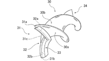
- the swirl flow generating ribbon has a first end point set at one of the radially outer end portions of the swirl flow generating ribbon and a radially outer side of the swirl flow generating ribbon at the end portion on the outflow side of the gas-liquid two-phase fluid.
- the present direction can be made to substantially coincide. Therefore, the liquid adhering to the swirl flow generating ribbon can maintain the state adhering to the first end edge or the second end edge when moving from the vicinity of the axial center toward the first and second end points. That is, even if the liquid adheres to the vicinity of the axial center of the swirling flow generating ribbon, it is guided toward the inner wall surface of the pipe while adhering to the swirling flow generating ribbon at the end of the ribbon. Re-scattering in the direction is suppressed.
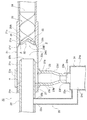
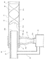
- FIG. 1 is an overall system diagram showing an exhaust gas recirculation system for an internal combustion engine to which a gas-liquid separator according to a first embodiment is applied. It is sectional drawing which shows the gas-liquid separator of Example 1.
- FIG. It is a perspective view which shows the swirl
- FIG. It is a side view of the swirl flow generation ribbon of Example 1.
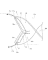
- FIG. 5 is a cross-sectional view taken along line AA in FIG. It is a whole explanatory drawing which shows the flow of the gas-liquid two-phase fluid in the gas-liquid separation apparatus of Example 1, and the isolate
- FIG. 9B is a sectional view taken along line BB in FIG. 9B.
- Example 1 First, the configuration of the gas-liquid separation device according to the first embodiment will be described by dividing it into “the overall system configuration of the application example”, “the detailed configuration of the gas-liquid separation device”, and “the detailed configuration of the swirling flow generating ribbon”.
- An intake port 2a is formed at the end of the intake passage 2. From the intake port 2a side, an air filter 4 for intake filtration, a compressor 5a of a turbocharger 5, an intercooler 6 for cooling intake air, and intake air A throttle valve 7 for adjusting the amount is provided. In the exhaust passage 3, a turbine 5 b of the turbocharger 5, an exhaust purification catalyst 8 for purifying exhaust, and an exhaust throttle valve 9 for adjusting the exhaust flow rate are provided in order from the internal combustion engine 1 side. . A muffler 10 is provided on the downstream side of the exhaust throttle valve 9, and an exhaust port 3a is formed at the end thereof.
- the exhaust port 21a is opened in the axial direction of the inlet pipe 21, and the drain port 21b is opened in the radial direction of the inlet pipe 21 and downward in the gravitational direction.
- the inner wall surface 21c of the inlet pipe 21 is formed with a tapered surface 21d that gradually increases in diameter along the flow direction of the gas-liquid two-phase fluid. That is, the inner diameter of the inlet pipe 21 is the smallest at the swivel portion 26A located upstream in the flow direction of the gas-liquid two-phase fluid from the tapered surface 21d, and gradually increases at the intermediate portion 26B where the tapered surface 21d is formed.
- a ring member 27 that seals the gap ⁇ generated between the outlet pipe 21a of the inlet pipe 21 and the inner pipe 22 is fitted.
- the ring member 27 has a cylindrical shape surrounding the entire circumference of the inner pipe 22, and the outer peripheral surface is in airtight contact with the inner peripheral surface of the inlet pipe 21, and the inner peripheral surface is in an airtight state with the outer peripheral surface of the inner pipe 22. In contact.
- the axial end of the ring member 27 in the inlet pipe 21 coincides with the most downstream portion of the peripheral edge of the drain port 21b in the axial position. That is, although the ring member 27 does not overlap with the opening region of the drain port 21b, the ring member 27 is installed without opening a gap in the axial direction with the opening region of the drain port 21b.
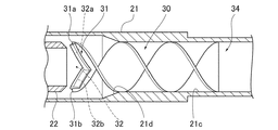
- the swirl flow generating ribbon 30 is formed of a strip-shaped plate member that is spirally twisted, and is disposed in the swivel portion 26 A of the inlet pipe 21.
- the swirling flow generating ribbon 30 has a radial dimension R (see FIG. 4) set to be equal to the inner diameter dimension of the swivel portion 26 ⁇ / b> A, is installed coaxially with the inlet pipe 21, and has a peripheral edge of the inlet pipe 21. It is in contact with the inner wall surface 21c.
- the cut portion 32 includes a first end edge 32a connecting the first end point 31a and the center end point 31c, and a second end edge 32b connecting the second end point 31b and the center end point 31c. is doing. That is, the cut portion 32 is formed by cutting out a region surrounded by the first end edge 32a, the second end edge 32b, and the end line L in the end portion 31 of the swirl flow generating ribbon 30 in a V shape. Is formed.
- the start end 34 of the swirling flow generating ribbon 30 on the inflow side of the gas-liquid two-phase fluid has a first start end point 34a, a second start end point 34b, and a center start end point 34c.
- the first starting end point 34 a is set to one of the radially outer starting ends of the swirling flow generating ribbon 30.
- the second starting end point 34 b is set to the other of the radially outer starting ends of the swirling flow generating ribbon 30.
- the center start point 34c is on the axis O of the swirl flow generating ribbon 30, and the first start point 34a and the second start point 34b are aligned in the axial direction.
- the drain port 21b opens downward in the direction of gravity, and the second pipe member 23b of the drain pipe 23 extends along the direction of gravity, so that the liquid flowing into the separation portion 26C is drained by its own weight. It flows down from 21b into the second pipe member 23b.
- the outer diameter of the inner pipe 22 is smaller than the inner diameter of the separation portion 26C of the inlet pipe 21, the liquid adhering to the inner wall surface 21c of the inlet pipe 21 is prevented from entering the inner pipe 22. Is done. That is, the liquid that has flowed into the separation portion 26C enters between the inlet pipe 21 and the inner pipe 22, and is prevented from flowing into the inner pipe 22.
- the inner pipe 22 is inserted into the inlet pipe 21, the expansion of the pipe diameter can be suppressed, and the space necessary for installing the gas-liquid separator 20 can be suppressed.
- the axial direction end of the ring member 27 in the inlet pipe 21 coincides with the most downstream portion of the peripheral edge of the drain port 21b.
- the liquid that has become droplets by adhering to the spiral surfaces 30a, 30b of the swirl flow generating ribbon 30 remains radially attached to the spiral surfaces 30a, 30b by the swirl flow.
- the liquid droplets flow toward the outside in the radial direction of the swirl flow generating ribbon 30 while being swept away downstream in the flow direction of the gas-liquid two-phase fluid.
- the liquid adhering to the spiral surfaces 30a and 30b of the swirl flow generating ribbon 30 is pushed to the downstream side in the flow direction of the gas-liquid two-phase fluid by the swirl flow, and radially outward of the swirl flow generating ribbon 30. It flows toward.
- the folded structure 33 that is folded back to the inflow side of the gas-liquid two-phase fluid is formed on both the first edge 32a and the second edge 32b. Therefore, the liquid pushed to the first end edge 32a or the second end edge 32b while adhering to the spiral surfaces 30a, 30b is directed to the downstream side in the flow direction of the gas-liquid two-phase fluid by the folded structure 33. Is blocked. That is, the liquid flows radially outward of the swirl flow generating ribbon 30 along the gap between the first end edge 32a and the first folded piece 33a or the gap between the second end edge 32b and the second folded piece 33b. It flows toward you. Thus, the liquid can be guided to the inner wall surface 21c of the inlet pipe 21 while preventing the liquid from separating from the first and second end edges 32a and 32b, and the liquid separation performance can be further improved. .
- the folded structure 33 is formed between the center terminal point 31c and the first terminal point 31a and between the center terminal point 31c and the second terminal point 31b.
- a gap ⁇ is formed between both ends in the radial direction and the inner wall surface 21 c of the inlet pipe 21. Therefore, the liquid that has been prevented from going downstream in the gas-liquid two-phase fluid flow direction by the folding structure 33 is directed toward the downstream side in the gas-liquid two-phase fluid flow direction at both radial ends of the folding structure 33. It becomes possible to flow out. This prevents the liquid from accumulating in the gap between the first end edge 32a and the first folded piece 33a or the gap between the second end edge 32b and the second folded piece 33b. The liquid can be promptly guided to the wall surface 21c.
- a gas-liquid two-phase fluid flowing through the pipe is swirled by a swirl flow generating ribbon 30 formed by a spirally twisted plate member and disposed in the pipe, and the liquid is circulated by centrifugal force.
- the gas-liquid separation device 20 that leads to the inner wall surface 21c of The piping is separated from the gas-liquid two-phase fluid at a position downstream of the swirling flow generating ribbon 30 in the flow direction of the gas-liquid two-phase fluid, with the swirling flow generating ribbon 30 being disposed inside.
- the swirl flow generating ribbon 30 has a first end point 31a set at one of the radially outer ends of the swirl flow generating ribbon 30 at the end portion 31 on the outflow side of the gas-liquid two-phase fluid, and the swirl A second terminal point 31b set on the other of the radially outer ends of the flow generating ribbon 30, and an axis O of the swirling flow generating ribbon 30, the first terminal point 31a and the second terminal point A center end point 31c set on the inflow side of the gas-liquid two-phase fluid than 31b, and A cut portion having a first end edge 32a connecting the first end point 31a and the center end point 31c, and a second end edge 32b connecting the second end point 31b and the center end point 31c. 32 is provided. Thereby, while improving the separation performance of the liquid adhering to the swirling flow generation
- the folding structure 33 is formed between the center terminal point 31c and the first terminal point 31a and between the central terminal point 31c and the second terminal point 31b.
- the configuration whereby, in addition to the effect of (2) above, the liquid is accumulated in the gap between the first end edge 32a and the first folded piece 33a and the gap between the second end edge 32b and the second folded piece 33b. While preventing, the liquid can be guided to the inner wall surface 21c of the inlet pipe 21.
- the inner wall surface 21c of the inlet pipe 21 is formed with a tapered surface 21d that gradually increases in diameter along the flow direction of the gas-liquid two-phase fluid
- the swirling flow generating ribbon 30 is configured such that at least the first terminal point 31a and the second terminal point 31b are inserted inside the tapered surface 21d.
- the inlet pipe 21 is provided with a drain pipe 23 connected to the drain port 21b, and a water storage tank 24 provided at a tip 23f of the drain pipe 23,
- the inner pipe 22 is provided with a bypass pipe 25 that communicates with the inside of the water storage tank 24. Thereby, the inside of the water storage tank 24 is made negative by the airflow flowing through the inner pipe 22, and the flow of the liquid flowing down the drainage pipe 23 can be made smooth.
- Example 1 As mentioned above, although the gas-liquid separator of this invention has been demonstrated based on Example 1, it is not restricted to this Example 1 about a concrete structure, The summary of the invention which concerns on each claim of a claim Design changes and additions are permitted as long as they do not deviate from.
- Example 1 the example which formed the folding structure 33 in the 1st end edge 32a and the 2nd end edge 32b of the terminal part 31 of the swirl
- the present invention is not limited to this.
- the extending direction of the first and second end edges 32a and 32b substantially coincides with the flow direction of the liquid pushed away by the swirling flow while adhering to the swirling flow generating ribbon 30, so that the swirling flow is generated.
- the ribbon 30 can be guided toward the inner wall surface 21 c of the inlet pipe 21 while being attached to the spiral surfaces 30 a and 30 b at the terminal end portion 31.
- a tapered surface 21d is formed on the inner wall surface 21c of the inlet pipe 21, and at least the first and second terminal points 31a and 31b of the swirl flow generating ribbon 30 are inserted inside the tapered surface 21d.
- An example was given.
- the tapered surface 21d may not be formed. Even in this case, the liquid separated from the gas-liquid two-phase fluid can flow into the drain port 21b by the swirl flow.
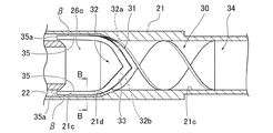
- the swirl flow generating ribbon 30 arranged in the swivel portion 26A is extended until the end portion 31 is inserted into the separation portion 26C of the inlet pipe 21, and the end portion 31 is opened in the inner pipe 22. It may be close to 22b.
- the first and second terminal points 31a and 31b of the swirling flow generating ribbon 30 are inserted inside the tapered surface 21d, and the first and second end edges of the swirling flow generating ribbon 30 are inserted.
- Both ends in the radial direction of the folded structure 33 provided in 32 a and 32 b may be extended along the inner wall surface 21 c of the inlet pipe 21. That is, extension portions 35 that are inserted into the separation portion 26 ⁇ / b> C of the inlet pipe 21 may be provided at both ends in the radial direction of the folded structure 33.
- the extension 35 is formed in a V-shaped cross section by the first and second folded pieces 33a and 33b (see FIG. 9C).
- the extension 35 by extending the extension 35 until the tip 35a reaches a position downstream of the opening 22b of the inner pipe 22, the liquid flowing between the first folded piece 33a and the second folded piece 33b of the folded structure 33 is allowed to flow.
- the inner wall 21c can be guided without being scattered in the inner pipe 22. Further, by maintaining the gap ⁇ between the extension portion 35 of the folding structure 33 and the inner wall surface 21c of the inlet pipe 21, the liquid flowing along the folding structure 33 can be smoothly guided to the inner wall surface 21c. .
- the start end portion 34 of the swirling flow generating ribbon 30 is erected along the direction of gravity.
- the swirl flow generating ribbon 30 may be installed so that the start end portion 34 is horizontal with respect to the direction of gravity.
- the liquid guided to the inner wall surface 21c inside the inlet pipe 21 can easily flow under the pipe under its own weight, and it is possible to effectively prevent the liquid separated from the gas from splashing again. it can.
- the water storage tank 24 is connected to the drain pipe 23 and the liquid separated from the gas-liquid two-phase fluid is stored.
- the drain pipe 23 and the water tank 24 are not necessarily installed. Also good.
- the liquid separated in the inlet pipe 21 may be discharged from the drain port 21b without storing.
- the first end edge 32a and the second end edge 32b are both formed in a straight line shape, and the cut portion 32 is formed by cutting out the end portion 31 of the swirl flow generating ribbon 30 in a V shape.
- the present invention is not limited to this. Since the center end point 31c only needs to be set on the inflow side of the gas-liquid two-phase fluid with respect to the first end point 31a and the second end point 32b, the first and second end edges 32a and 32b are curved. May be.
- Example 1 the example which applied the swirling flow generator for gas-liquid separation of this invention to the exhaust gas recirculation system S of the internal combustion engine 1 was shown.
- the present invention is not limited to this.
- the present invention may be applied to a refrigeration cycle apparatus to separate a gas refrigerant and a liquid refrigerant. That is, the gas-liquid separation swirl flow generator of the present invention can be applied to an apparatus for separating gas and liquid from a gas-liquid two-phase fluid.
Abstract
L'invention concerne un dispositif de séparation gaz-liquide qui améliore la performance de séparation d'un liquide adhérant à un ruban de génération d'écoulement tourbillonnant, et qui peut supprimer l'espace d'installation nécessaire. Ce dispositif de séparation gaz-liquide comprend : un tuyau d'entrée (21) dans lequel le ruban de génération d'écoulement tourbillonnant (30) est disposé, et dans lequel un orifice d'échappement (21a) pour la sortie du gaz séparé et un orifice de drainage (21b) pour la sortie du liquide séparé sont formés ; et un tuyau interne (22) qui a un diamètre externe plus petit que celui du tuyau d'entrée (21), et qui est inséré au niveau d'une extrémité dans l'orifice d'échappement (21a) et s'ouvre en aval du ruban de génération d'écoulement tourbillonnant (30). En outre, au niveau de la partie d'extrémité (31) du ruban de génération d'écoulement tourbillonnant (30), une partie découpe (32) relie un premier point d'extrémité (31a) disposé sur une extrémité radialement externe, un second point d'extrémité (31b) disposé sur l'autre extrémité radialement externe, et un point d'extrémité central (31c) qui, disposé sur l'axe (O), est placé vers le côté d'entrée de fluide à deux phases gaz-liquide par rapport aux premier et second points d'extrémité (31a, 31b).<u />
Applications Claiming Priority (2)
| Application Number | Priority Date | Filing Date | Title |
|---|---|---|---|
| JP2015246468 | 2015-12-17 | ||
| JP2015-246468 | 2015-12-17 |
Publications (1)
| Publication Number | Publication Date |
|---|---|
| WO2017104184A1 true WO2017104184A1 (fr) | 2017-06-22 |
Family
ID=59056427
Family Applications (2)
| Application Number | Title | Priority Date | Filing Date |
|---|---|---|---|
| PCT/JP2016/075523 WO2017104184A1 (fr) | 2015-12-17 | 2016-08-31 | Dispositif de séparation gaz-liquide |
| PCT/JP2016/086531 WO2017104531A1 (fr) | 2015-12-17 | 2016-12-08 | Dispositif de séparation gaz-liquide |
Family Applications After (1)
| Application Number | Title | Priority Date | Filing Date |
|---|---|---|---|
| PCT/JP2016/086531 WO2017104531A1 (fr) | 2015-12-17 | 2016-12-08 | Dispositif de séparation gaz-liquide |
Country Status (5)
| Country | Link |
|---|---|
| US (1) | US10828590B2 (fr) |
| EP (1) | EP3391952B1 (fr) |
| JP (1) | JP6634091B2 (fr) |
| CN (1) | CN108697958B (fr) |
| WO (2) | WO2017104184A1 (fr) |
Cited By (2)
| Publication number | Priority date | Publication date | Assignee | Title |
|---|---|---|---|---|
| CN111566334A (zh) * | 2017-10-25 | 2020-08-21 | 臼井国际产业株 | 气液分离装置 |
| US11313330B2 (en) | 2017-10-25 | 2022-04-26 | Usui Co., Ltd. | Gas-liquid separator |
Families Citing this family (12)
| Publication number | Priority date | Publication date | Assignee | Title |
|---|---|---|---|---|
| JP6934297B2 (ja) | 2016-12-08 | 2021-09-15 | 臼井国際産業株式会社 | 気液分離装置 |
| JP6730175B2 (ja) * | 2016-12-16 | 2020-07-29 | 臼井国際産業株式会社 | Egrクーラ |
| WO2019130393A1 (fr) * | 2017-12-25 | 2019-07-04 | 三菱電機株式会社 | Séparateur et dispositif à cycle frigorifique |
| IT201800003381A1 (it) * | 2018-03-08 | 2019-09-08 | Hsd Holding Smart Device S R L | Un assieme di ventilazione |
| DE102019110247A1 (de) * | 2018-04-19 | 2019-10-24 | Mann+Hummel Gmbh | Rohrabschnitt eines Ansaugrohrs für einen Luftansaugtrakt einer Brennkraftmaschine |
| US11660557B2 (en) | 2018-08-27 | 2023-05-30 | Sierra Space Corporation | Low-gravity water capture device with water stabilization |
| US11207628B2 (en) * | 2018-09-27 | 2021-12-28 | Noram Engineering And Constructors Ltd. | Processes and devices for separating entrainment from sulphuric acid plant process gas |
| CN109578251A (zh) * | 2018-12-27 | 2019-04-05 | 四川金象赛瑞化工股份有限公司 | 一种压缩机取气装置及方法 |
| JP7312693B2 (ja) * | 2019-12-25 | 2023-07-21 | マーレジャパン株式会社 | 気泡分離器、および気泡分離器を備える自動車の流体回路 |
| EP4083541A4 (fr) * | 2019-12-27 | 2022-12-07 | Mitsubishi Electric Corporation | Dispositif de séparation gaz-liquide et dispositif à cycle de réfrigération |
| EP3944888A1 (fr) * | 2020-07-29 | 2022-02-02 | Hamilton Sundstrand Corporation | Collecteur d'eau annulaire à haute pression comprenant des ailettes de tourbillonnement axiales pour un système de commande environnemental à cycle d'air |
| CN115155219B (zh) * | 2022-08-22 | 2023-09-08 | 浙江洛森压缩机股份有限公司 | 一种气液分离排污系统 |
Citations (5)
| Publication number | Priority date | Publication date | Assignee | Title |
|---|---|---|---|---|
| JPS56501351A (fr) * | 1979-10-24 | 1981-09-24 | ||
| JPH042839Y2 (fr) * | 1985-07-12 | 1992-01-30 | ||
| JP2005199161A (ja) * | 2004-01-15 | 2005-07-28 | Tlv Co Ltd | 気液分離器 |
| US20090065431A1 (en) * | 2006-02-20 | 2009-03-12 | Knut Bakke | In-line separator |
| US20140116255A1 (en) * | 2012-10-31 | 2014-05-01 | Intevep, S.A. | Axial gas-liquid cyclone separator |
Family Cites Families (59)
| Publication number | Priority date | Publication date | Assignee | Title |
|---|---|---|---|---|
| US1735298A (en) * | 1927-02-09 | 1929-11-12 | American Blower Corp | Apparatus for collecting dust particles |
| GB359739A (en) | 1930-11-04 | 1931-10-29 | Erich Bechtel | Improvements in or relating to smoke-washing apparatus |
| GB487399A (en) * | 1935-09-26 | 1938-06-16 | Refining Inc | Improvements in or relating to a process for producing soap |
| CH472638A (de) | 1967-01-26 | 1969-05-15 | Eidgenoess Flugzeugwerk Emmen | Gerät zum Abscheiden eines flüssigen und/oder dampfförmigen Mediums aus einem Trägergas und dessen Verwendung in Flugzeugen |
| US3433361A (en) * | 1967-05-31 | 1969-03-18 | Sundstrand Corp | Coolant filter combination |
| US3517821A (en) * | 1968-11-29 | 1970-06-30 | Donaldson Co Inc | Deflecting element for centrifugal separators |
| US3713279A (en) * | 1970-06-17 | 1973-01-30 | L Moore | Gas-liquid separator |
| US3813854A (en) * | 1972-07-07 | 1974-06-04 | N Hortman | Centrifugal separator having axial-flow vortex generator |
| US4008059A (en) * | 1975-05-06 | 1977-02-15 | The United States Of America As Represented By The Secretary Of The Army | Centrifugal separator |
| JPS5649020Y2 (fr) * | 1976-08-13 | 1981-11-16 | ||
| JPS5326762A (en) | 1976-08-26 | 1978-03-13 | Babcock Hitachi Kk | Sprayer for reducing agent for nox |
| US4187089A (en) * | 1977-01-24 | 1980-02-05 | Maloney-Crawford Tank Corporation | Horizontal vapor-liquid separator |
| US4162906A (en) * | 1977-05-05 | 1979-07-31 | Donaldson Company, Inc. | Side outlet tube |
| US4180391A (en) * | 1977-06-13 | 1979-12-25 | Perry Equipment Co. | Gas particulate separator with scavenging gas separation device |
| US4311494A (en) * | 1977-09-26 | 1982-01-19 | Facet Enterprises, Inc. | Axial flow gas cleaning device |
| DE2918765A1 (de) * | 1979-05-10 | 1980-11-13 | Kloeckner Humboldt Deutz Ag | Fliehkraftstaubabscheidersystem mit mehreren stufen |
| US4622048A (en) | 1985-01-17 | 1986-11-11 | American Standard Inc. | Liquid-gas separator |
| FR2632216B1 (fr) | 1988-06-02 | 1992-07-10 | Cyclofil Pty Ltd | Dispositif de separation a tube a tourbillon |
| ATE110985T1 (de) * | 1988-06-02 | 1994-09-15 | Cyclofil Pty Ltd | Wirbelrohr-abscheider. |
| JPH0670295B2 (ja) | 1990-04-16 | 1994-09-07 | 株式会社スリーデイコンポリサーチ | ロッド方式三次元織物織機における筬打ち方法及び装置 |
| JP2507606Y2 (ja) * | 1990-07-06 | 1996-08-14 | 株式会社小松製作所 | 大型ダンプトラックの駆動系の冷却装置用エアクリ―ナ |
| ZA931264B (en) * | 1992-02-27 | 1993-09-17 | Atomic Energy South Africa | Filtration. |
| JP3445108B2 (ja) * | 1997-08-29 | 2003-09-08 | アマノ株式会社 | 旋回流案内羽根 |
| AUPP624298A0 (en) * | 1998-09-30 | 1998-10-22 | Alcos Technologies Pty Ltd | Cyclonic evaporator |
| DE10029498A1 (de) * | 2000-06-21 | 2002-01-03 | Mann & Hummel Filter | Ansaugsystem |
| WO2002020137A2 (fr) | 2000-09-11 | 2002-03-14 | Stephen Kotze | Separateur d'eau |
| US6540917B1 (en) * | 2000-11-10 | 2003-04-01 | Purolator Facet Inc. | Cyclonic inertial fluid cleaning apparatus |
| NO318709B1 (no) * | 2000-12-22 | 2005-05-02 | Statoil Asa | Innretning for separasjon av en vaeske fra en flerfase-fluidstrom |
| DE10129198B4 (de) * | 2001-06-19 | 2004-07-22 | Balcke-Dürr GmbH | Zentrifugalabscheider zum Abscheiden von Wasser |
| JP2003062416A (ja) | 2001-08-27 | 2003-03-04 | Maruyasu Industries Co Ltd | 気液分離器 |
| NO315188B1 (no) | 2001-11-07 | 2003-07-28 | Consept As | Dråpefangersyklon |
| JP2003190725A (ja) | 2001-12-25 | 2003-07-08 | Maruyasu Industries Co Ltd | 気液分離器 |
| NL1020531C2 (nl) | 2002-05-03 | 2003-11-04 | Spark Technologies And Innovat | Inrichting en systeem voor het scheiden van een mengsel. |
| NO321170B1 (no) * | 2002-06-21 | 2006-03-27 | Statoil Asa | Sammenstilling for a separere ut vaeske fra en flerfasestrom |
| DE10330296A1 (de) * | 2003-07-04 | 2005-02-03 | Mann + Hummel Gmbh | Abscheidevorrichtung |
| JP2005160187A (ja) | 2003-11-25 | 2005-06-16 | Maruyasu Industries Co Ltd | 気液分離可能な燃料電池車両用マフラー |
| BRPI0508503B1 (pt) * | 2004-03-08 | 2015-01-13 | Reinz-Dichtungs-Gmbh | Dispositivo de separação de fluido e método para sua fabricação |
| EP1825130A1 (fr) | 2004-10-25 | 2007-08-29 | Behr GmbH & Co. KG | Condensateur d'un systeme de turbocompresseur et procede d'utilisation d'un tel systeme |
| JP2006205077A (ja) | 2005-01-28 | 2006-08-10 | Tadamitsu Mokuo | 螺旋構造体とそれを用いた気体内からの混合物分離装置及び熱交換装置 |
| JP4702666B2 (ja) | 2005-07-20 | 2011-06-15 | Smc株式会社 | ドレンセパレータ |
| JP4422691B2 (ja) * | 2006-02-28 | 2010-02-24 | 日立Geニュークリア・エナジー株式会社 | 気水分離器、沸騰水型原子炉及びスワラアセンブリ |
| EP1974790A1 (fr) * | 2007-03-26 | 2008-10-01 | Twister B.V. | Séparateur de fluide de cyclone |
| US7879123B2 (en) | 2007-09-27 | 2011-02-01 | Pall Corporation | Inertial separator |
| AU2008350168A1 (en) * | 2008-02-06 | 2009-08-13 | Statoil Petroleum As | Gas-liquid separator |
| US8043394B2 (en) * | 2008-03-21 | 2011-10-25 | GM Global Technology Operations LLC | Particulate matter filter assembly with a flow device |
| NL2002714C2 (nl) | 2009-04-03 | 2010-10-05 | Advanced Tail End Oil Company N V | Inrichting voor het in fracties separeren van een verscheidene fracties bevattend fluã¯dum met dubbele separatie. |
| CN102725070B (zh) * | 2009-12-15 | 2014-03-12 | 巴斯夫欧洲公司 | 具有后接离心式分离器的重力式预分离器的分离设备 |
| US8425641B2 (en) * | 2010-06-30 | 2013-04-23 | General Electric Company | Inlet air filtration system |
| US9764265B2 (en) * | 2011-09-30 | 2017-09-19 | Mueller Environmental Designs, Inc. | Swirl helical elements for a viscous impingement particle collection and hydraulic removal system |
| CA2858881C (fr) | 2011-12-16 | 2020-02-25 | Shell Internationale Research Maatschappij B.V. | Dispositif de separation comprenant une coupelle rotative |
| CA2859847C (fr) * | 2011-12-22 | 2019-01-22 | Statoil Petroleum As | Procede et systeme de separation de fluides comportant un systeme de regulation integre |
| CN102518498A (zh) | 2011-12-25 | 2012-06-27 | 浙江大学 | 用于旋转气液混合流动噪声控制装置 |
| GB2507662B8 (en) | 2012-10-31 | 2015-01-07 | Intevep Sa | Axial Gas-Liquid Cyclone Separator |
| US9504947B2 (en) * | 2012-11-13 | 2016-11-29 | Cummins Filtration Ip, Inc. | Air filter assemblies and carrier frames having vortex-generating flow guide |
| RU2579079C1 (ru) * | 2014-10-03 | 2016-03-27 | Открытое акционерное общество "Генерация Финанс" | Прямоточный центробежный газожидкостный сепаратор |
| US9675920B2 (en) * | 2014-12-19 | 2017-06-13 | Caterpillar Inc. | Apparatus for air precleaner and precleaner |
| NO341179B1 (en) * | 2015-08-28 | 2017-09-04 | Fjords Proc As | Axial flow demister |
| US10159990B2 (en) * | 2015-09-06 | 2018-12-25 | Harvey Industries Co., Ltd. | Dust separation apparatus and intelligent control system including the apparatus |
| US10710013B2 (en) * | 2017-03-12 | 2020-07-14 | Mueller Environmental Designs, Inc. | Compact axial flow separator |
-
2016
- 2016-08-31 WO PCT/JP2016/075523 patent/WO2017104184A1/fr active Application Filing
- 2016-12-08 EP EP16875511.4A patent/EP3391952B1/fr active Active
- 2016-12-08 CN CN201680074276.1A patent/CN108697958B/zh active Active
- 2016-12-08 US US16/062,572 patent/US10828590B2/en active Active
- 2016-12-08 JP JP2017556008A patent/JP6634091B2/ja active Active
- 2016-12-08 WO PCT/JP2016/086531 patent/WO2017104531A1/fr active Application Filing
Patent Citations (5)
| Publication number | Priority date | Publication date | Assignee | Title |
|---|---|---|---|---|
| JPS56501351A (fr) * | 1979-10-24 | 1981-09-24 | ||
| JPH042839Y2 (fr) * | 1985-07-12 | 1992-01-30 | ||
| JP2005199161A (ja) * | 2004-01-15 | 2005-07-28 | Tlv Co Ltd | 気液分離器 |
| US20090065431A1 (en) * | 2006-02-20 | 2009-03-12 | Knut Bakke | In-line separator |
| US20140116255A1 (en) * | 2012-10-31 | 2014-05-01 | Intevep, S.A. | Axial gas-liquid cyclone separator |
Cited By (4)
| Publication number | Priority date | Publication date | Assignee | Title |
|---|---|---|---|---|
| CN111566334A (zh) * | 2017-10-25 | 2020-08-21 | 臼井国际产业株 | 气液分离装置 |
| CN111566334B (zh) * | 2017-10-25 | 2022-04-19 | 臼井国际产业株式会社 | 气液分离装置 |
| US11313330B2 (en) | 2017-10-25 | 2022-04-26 | Usui Co., Ltd. | Gas-liquid separator |
| US11421630B2 (en) | 2017-10-25 | 2022-08-23 | Usui Co., Ltd. | Gas-liquid separator |
Also Published As
| Publication number | Publication date |
|---|---|
| US20180361290A1 (en) | 2018-12-20 |
| US10828590B2 (en) | 2020-11-10 |
| CN108697958B (zh) | 2021-03-12 |
| WO2017104531A1 (fr) | 2017-06-22 |
| EP3391952A4 (fr) | 2019-08-07 |
| JP6634091B2 (ja) | 2020-01-22 |
| CN108697958A (zh) | 2018-10-23 |
| EP3391952B1 (fr) | 2021-04-21 |
| JPWO2017104531A1 (ja) | 2018-11-01 |
| EP3391952A1 (fr) | 2018-10-24 |
Similar Documents
| Publication | Publication Date | Title |
|---|---|---|
| WO2017104184A1 (fr) | Dispositif de séparation gaz-liquide | |
| WO2017104183A1 (fr) | Générateur d'écoulement tourbillonnant pour séparation gaz-liquide | |
| US20140208744A1 (en) | Egr apparatus for internal combustion engine | |
| WO2019082772A1 (fr) | Séparateur gaz-liquide | |
| EP3552685B1 (fr) | Dispositif de séparation gaz-liquide | |
| WO2018110351A1 (fr) | Refroidisseur rge | |
| EP4268926A1 (fr) | Dispositif de séparation gaz-liquide | |
| US11421630B2 (en) | Gas-liquid separator | |
| EP4268927A1 (fr) | Dispositif de séparation gaz-liquide |
Legal Events
| Date | Code | Title | Description |
|---|---|---|---|
| 121 | Ep: the epo has been informed by wipo that ep was designated in this application |
Ref document number: 16875170 Country of ref document: EP Kind code of ref document: A1 |
|
| NENP | Non-entry into the national phase |
Ref country code: DE |
|
| 122 | Ep: pct application non-entry in european phase |
Ref document number: 16875170 Country of ref document: EP Kind code of ref document: A1 |