WO2017104184A1 - Gas-liquid separation device - Google Patents
Gas-liquid separation device Download PDFInfo
- Publication number
- WO2017104184A1 WO2017104184A1 PCT/JP2016/075523 JP2016075523W WO2017104184A1 WO 2017104184 A1 WO2017104184 A1 WO 2017104184A1 JP 2016075523 W JP2016075523 W JP 2016075523W WO 2017104184 A1 WO2017104184 A1 WO 2017104184A1
- Authority
- WO
- WIPO (PCT)
- Prior art keywords
- gas
- liquid
- pipe
- flow generating
- generating ribbon
- Prior art date
Links
- 239000007788 liquid Substances 0.000 title claims abstract description 194
- 238000000926 separation method Methods 0.000 title claims abstract description 48
- 239000012530 fluid Substances 0.000 claims abstract description 66
- XLYOFNOQVPJJNP-UHFFFAOYSA-N water Substances O XLYOFNOQVPJJNP-UHFFFAOYSA-N 0.000 claims description 18
- 238000003860 storage Methods 0.000 claims description 11
- 238000007599 discharging Methods 0.000 claims 2
- 238000009434 installation Methods 0.000 abstract description 5
- 230000005484 gravity Effects 0.000 description 10
- 238000002485 combustion reaction Methods 0.000 description 9
- 230000002093 peripheral effect Effects 0.000 description 7
- 230000000694 effects Effects 0.000 description 5
- 238000004519 manufacturing process Methods 0.000 description 5
- 238000012986 modification Methods 0.000 description 5
- 230000004048 modification Effects 0.000 description 5
- 238000011144 upstream manufacturing Methods 0.000 description 5
- 238000001816 cooling Methods 0.000 description 3
- 239000003054 catalyst Substances 0.000 description 2
- 238000005520 cutting process Methods 0.000 description 2
- 238000009795 derivation Methods 0.000 description 2
- 238000010586 diagram Methods 0.000 description 2
- 230000006698 induction Effects 0.000 description 2
- 238000002955 isolation Methods 0.000 description 2
- 238000000746 purification Methods 0.000 description 2
- 239000003507 refrigerant Substances 0.000 description 2
- 238000007792 addition Methods 0.000 description 1
- 230000015572 biosynthetic process Effects 0.000 description 1
- 238000004891 communication Methods 0.000 description 1
- 230000007423 decrease Effects 0.000 description 1
- 238000001914 filtration Methods 0.000 description 1
- 238000000034 method Methods 0.000 description 1
- 238000002156 mixing Methods 0.000 description 1
- 238000005057 refrigeration Methods 0.000 description 1
- 238000009423 ventilation Methods 0.000 description 1
Images


Classifications
-
- B—PERFORMING OPERATIONS; TRANSPORTING
- B01—PHYSICAL OR CHEMICAL PROCESSES OR APPARATUS IN GENERAL
- B01D—SEPARATION
- B01D45/00—Separating dispersed particles from gases or vapours by gravity, inertia, or centrifugal forces
- B01D45/12—Separating dispersed particles from gases or vapours by gravity, inertia, or centrifugal forces by centrifugal forces
- B01D45/16—Separating dispersed particles from gases or vapours by gravity, inertia, or centrifugal forces by centrifugal forces generated by the winding course of the gas stream, the centrifugal forces being generated solely or partly by mechanical means, e.g. fixed swirl vanes
-
- B—PERFORMING OPERATIONS; TRANSPORTING
- B01—PHYSICAL OR CHEMICAL PROCESSES OR APPARATUS IN GENERAL
- B01D—SEPARATION
- B01D45/00—Separating dispersed particles from gases or vapours by gravity, inertia, or centrifugal forces
- B01D45/12—Separating dispersed particles from gases or vapours by gravity, inertia, or centrifugal forces by centrifugal forces
-
- B—PERFORMING OPERATIONS; TRANSPORTING
- B04—CENTRIFUGAL APPARATUS OR MACHINES FOR CARRYING-OUT PHYSICAL OR CHEMICAL PROCESSES
- B04C—APPARATUS USING FREE VORTEX FLOW, e.g. CYCLONES
- B04C3/00—Apparatus in which the axial direction of the vortex flow following a screw-thread type line remains unchanged ; Devices in which one of the two discharge ducts returns centrally through the vortex chamber, a reverse-flow vortex being prevented by bulkheads in the central discharge duct
- B04C3/02—Apparatus in which the axial direction of the vortex flow following a screw-thread type line remains unchanged ; Devices in which one of the two discharge ducts returns centrally through the vortex chamber, a reverse-flow vortex being prevented by bulkheads in the central discharge duct with heating or cooling, e.g. quenching, means
-
- B—PERFORMING OPERATIONS; TRANSPORTING
- B04—CENTRIFUGAL APPARATUS OR MACHINES FOR CARRYING-OUT PHYSICAL OR CHEMICAL PROCESSES
- B04C—APPARATUS USING FREE VORTEX FLOW, e.g. CYCLONES
- B04C3/00—Apparatus in which the axial direction of the vortex flow following a screw-thread type line remains unchanged ; Devices in which one of the two discharge ducts returns centrally through the vortex chamber, a reverse-flow vortex being prevented by bulkheads in the central discharge duct
- B04C3/06—Construction of inlets or outlets to the vortex chamber
-
- F—MECHANICAL ENGINEERING; LIGHTING; HEATING; WEAPONS; BLASTING
- F02—COMBUSTION ENGINES; HOT-GAS OR COMBUSTION-PRODUCT ENGINE PLANTS
- F02M—SUPPLYING COMBUSTION ENGINES IN GENERAL WITH COMBUSTIBLE MIXTURES OR CONSTITUENTS THEREOF
- F02M26/00—Engine-pertinent apparatus for adding exhaust gases to combustion-air, main fuel or fuel-air mixture, e.g. by exhaust gas recirculation [EGR] systems
- F02M26/50—Arrangements or methods for preventing or reducing deposits, corrosion or wear caused by impurities
-
- F—MECHANICAL ENGINEERING; LIGHTING; HEATING; WEAPONS; BLASTING
- F02—COMBUSTION ENGINES; HOT-GAS OR COMBUSTION-PRODUCT ENGINE PLANTS
- F02M—SUPPLYING COMBUSTION ENGINES IN GENERAL WITH COMBUSTIBLE MIXTURES OR CONSTITUENTS THEREOF
- F02M35/00—Combustion-air cleaners, air intakes, intake silencers, or induction systems specially adapted for, or arranged on, internal-combustion engines
- F02M35/02—Air cleaners
- F02M35/022—Air cleaners acting by gravity, by centrifugal, or by other inertial forces, e.g. with moistened walls
- F02M35/0223—Air cleaners acting by gravity, by centrifugal, or by other inertial forces, e.g. with moistened walls by centrifugal forces, e.g. cyclones
-
- F—MECHANICAL ENGINEERING; LIGHTING; HEATING; WEAPONS; BLASTING
- F02—COMBUSTION ENGINES; HOT-GAS OR COMBUSTION-PRODUCT ENGINE PLANTS
- F02M—SUPPLYING COMBUSTION ENGINES IN GENERAL WITH COMBUSTIBLE MIXTURES OR CONSTITUENTS THEREOF
- F02M35/00—Combustion-air cleaners, air intakes, intake silencers, or induction systems specially adapted for, or arranged on, internal-combustion engines
- F02M35/10—Air intakes; Induction systems
-
- B—PERFORMING OPERATIONS; TRANSPORTING
- B04—CENTRIFUGAL APPARATUS OR MACHINES FOR CARRYING-OUT PHYSICAL OR CHEMICAL PROCESSES
- B04C—APPARATUS USING FREE VORTEX FLOW, e.g. CYCLONES
- B04C3/00—Apparatus in which the axial direction of the vortex flow following a screw-thread type line remains unchanged ; Devices in which one of the two discharge ducts returns centrally through the vortex chamber, a reverse-flow vortex being prevented by bulkheads in the central discharge duct
- B04C2003/006—Construction of elements by which the vortex flow is generated or degenerated
-
- F—MECHANICAL ENGINEERING; LIGHTING; HEATING; WEAPONS; BLASTING
- F02—COMBUSTION ENGINES; HOT-GAS OR COMBUSTION-PRODUCT ENGINE PLANTS
- F02M—SUPPLYING COMBUSTION ENGINES IN GENERAL WITH COMBUSTIBLE MIXTURES OR CONSTITUENTS THEREOF
- F02M26/00—Engine-pertinent apparatus for adding exhaust gases to combustion-air, main fuel or fuel-air mixture, e.g. by exhaust gas recirculation [EGR] systems
- F02M26/02—EGR systems specially adapted for supercharged engines
- F02M26/04—EGR systems specially adapted for supercharged engines with a single turbocharger
- F02M26/05—High pressure loops, i.e. wherein recirculated exhaust gas is taken out from the exhaust system upstream of the turbine and reintroduced into the intake system downstream of the compressor
-
- F—MECHANICAL ENGINEERING; LIGHTING; HEATING; WEAPONS; BLASTING
- F02—COMBUSTION ENGINES; HOT-GAS OR COMBUSTION-PRODUCT ENGINE PLANTS
- F02M—SUPPLYING COMBUSTION ENGINES IN GENERAL WITH COMBUSTIBLE MIXTURES OR CONSTITUENTS THEREOF
- F02M26/00—Engine-pertinent apparatus for adding exhaust gases to combustion-air, main fuel or fuel-air mixture, e.g. by exhaust gas recirculation [EGR] systems
- F02M26/02—EGR systems specially adapted for supercharged engines
- F02M26/04—EGR systems specially adapted for supercharged engines with a single turbocharger
- F02M26/06—Low pressure loops, i.e. wherein recirculated exhaust gas is taken out from the exhaust downstream of the turbocharger turbine and reintroduced into the intake system upstream of the compressor
-
- F—MECHANICAL ENGINEERING; LIGHTING; HEATING; WEAPONS; BLASTING
- F02—COMBUSTION ENGINES; HOT-GAS OR COMBUSTION-PRODUCT ENGINE PLANTS
- F02M—SUPPLYING COMBUSTION ENGINES IN GENERAL WITH COMBUSTIBLE MIXTURES OR CONSTITUENTS THEREOF
- F02M26/00—Engine-pertinent apparatus for adding exhaust gases to combustion-air, main fuel or fuel-air mixture, e.g. by exhaust gas recirculation [EGR] systems
- F02M26/13—Arrangement or layout of EGR passages, e.g. in relation to specific engine parts or for incorporation of accessories
- F02M26/22—Arrangement or layout of EGR passages, e.g. in relation to specific engine parts or for incorporation of accessories with coolers in the recirculation passage
-
- Y—GENERAL TAGGING OF NEW TECHNOLOGICAL DEVELOPMENTS; GENERAL TAGGING OF CROSS-SECTIONAL TECHNOLOGIES SPANNING OVER SEVERAL SECTIONS OF THE IPC; TECHNICAL SUBJECTS COVERED BY FORMER USPC CROSS-REFERENCE ART COLLECTIONS [XRACs] AND DIGESTS
- Y02—TECHNOLOGIES OR APPLICATIONS FOR MITIGATION OR ADAPTATION AGAINST CLIMATE CHANGE
- Y02T—CLIMATE CHANGE MITIGATION TECHNOLOGIES RELATED TO TRANSPORTATION
- Y02T10/00—Road transport of goods or passengers
- Y02T10/10—Internal combustion engine [ICE] based vehicles
- Y02T10/12—Improving ICE efficiencies
Definitions
- the present invention relates to a gas-liquid separation device that swirls a gas-liquid two-phase fluid flowing in a pipe by a swirl flow generating ribbon and guides the liquid to the inner wall surface of the pipe by centrifugal force.
- a gas-liquid separation device that swirls a gas-liquid two-phase fluid flowing in a pipe by a swirl flow generating ribbon formed by spirally twisting a plate member and guides the liquid to the inner wall surface of the pipe by centrifugal force. It is known (see, for example, Patent Document 1). Further, a gas-liquid separation device is known in which a downstream portion of a pipe is inserted into another large-diameter pipe to form a double-pipe structure, and the separated gas and liquid are respectively flowed out (for example, Patent Document 2 and Patent). Reference 3). In such a gas-liquid separator, the liquid (water droplets) adhering to the swirl flow generating ribbon flows toward the inner wall surface of the pipe while adhering to the ribbon surface.
- the end portion of the swirling flow generating ribbon (the end portion on the outflow side of the gas-liquid two-phase fluid) has a straight edge along the ribbon radial direction.
- the liquid adhering to the vicinity of the axis of the generated ribbon was re-scattered into the gas without flowing toward the inner wall surface of the pipe at the end of the ribbon. Therefore, there has been a problem that the liquid separation performance is lowered.
- the installation space becomes large, and for example, it is difficult to install in a small space such as an exhaust pipe of an internal combustion engine. .
- the present invention has been made paying attention to the above problems, and provides a gas-liquid separation device capable of improving the separation performance of the liquid adhering to the swirl flow generating ribbon and suppressing the necessary installation space. Objective.
- the present invention is formed by a spirally twisted plate member, and swirling a gas-liquid two-phase fluid flowing through a pipe by a swirl flow generating ribbon arranged in the pipe, and then centrifuging It is a gas-liquid separation device that guides liquid to the inner wall surface of a pipe by force.
- the piping includes an inlet pipe and an inner pipe.
- the swirl flow generating ribbon is disposed inside, and the exhaust gas from which the gas separated from the gas-liquid two-phase fluid flows out downstream of the swirl flow generating ribbon in the flow direction of the gas-liquid two-phase fluid.
- An outlet and a drain outlet through which liquid separated from the gas-liquid two-phase fluid flows are formed.
- the inner pipe has one end inserted into the exhaust port, an outer diameter smaller than the inner diameter of the inlet pipe, and an opening opened at a position downstream of the swirl flow generating ribbon in the flow direction of the gas-liquid two-phase fluid.
- the swirl flow generating ribbon has a first end point set at one of the radially outer end portions of the swirl flow generating ribbon and a radially outer side of the swirl flow generating ribbon at the end portion on the outflow side of the gas-liquid two-phase fluid.
- the present direction can be made to substantially coincide. Therefore, the liquid adhering to the swirl flow generating ribbon can maintain the state adhering to the first end edge or the second end edge when moving from the vicinity of the axial center toward the first and second end points. That is, even if the liquid adheres to the vicinity of the axial center of the swirling flow generating ribbon, it is guided toward the inner wall surface of the pipe while adhering to the swirling flow generating ribbon at the end of the ribbon. Re-scattering in the direction is suppressed.
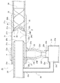
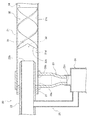
- FIG. 1 is an overall system diagram showing an exhaust gas recirculation system for an internal combustion engine to which a gas-liquid separator according to a first embodiment is applied. It is sectional drawing which shows the gas-liquid separator of Example 1.
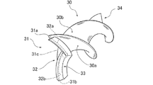
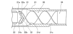
- FIG. It is a perspective view which shows the swirl
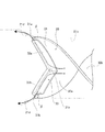
- FIG. It is a side view of the swirl flow generation ribbon of Example 1.
- FIG. 5 is a cross-sectional view taken along line AA in FIG. It is a whole explanatory drawing which shows the flow of the gas-liquid two-phase fluid in the gas-liquid separation apparatus of Example 1, and the isolate
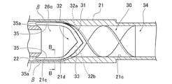
- FIG. 9B is a sectional view taken along line BB in FIG. 9B.
- Example 1 First, the configuration of the gas-liquid separation device according to the first embodiment will be described by dividing it into “the overall system configuration of the application example”, “the detailed configuration of the gas-liquid separation device”, and “the detailed configuration of the swirling flow generating ribbon”.
- An intake port 2a is formed at the end of the intake passage 2. From the intake port 2a side, an air filter 4 for intake filtration, a compressor 5a of a turbocharger 5, an intercooler 6 for cooling intake air, and intake air A throttle valve 7 for adjusting the amount is provided. In the exhaust passage 3, a turbine 5 b of the turbocharger 5, an exhaust purification catalyst 8 for purifying exhaust, and an exhaust throttle valve 9 for adjusting the exhaust flow rate are provided in order from the internal combustion engine 1 side. . A muffler 10 is provided on the downstream side of the exhaust throttle valve 9, and an exhaust port 3a is formed at the end thereof.
- the exhaust port 21a is opened in the axial direction of the inlet pipe 21, and the drain port 21b is opened in the radial direction of the inlet pipe 21 and downward in the gravitational direction.
- the inner wall surface 21c of the inlet pipe 21 is formed with a tapered surface 21d that gradually increases in diameter along the flow direction of the gas-liquid two-phase fluid. That is, the inner diameter of the inlet pipe 21 is the smallest at the swivel portion 26A located upstream in the flow direction of the gas-liquid two-phase fluid from the tapered surface 21d, and gradually increases at the intermediate portion 26B where the tapered surface 21d is formed.
- a ring member 27 that seals the gap ⁇ generated between the outlet pipe 21a of the inlet pipe 21 and the inner pipe 22 is fitted.
- the ring member 27 has a cylindrical shape surrounding the entire circumference of the inner pipe 22, and the outer peripheral surface is in airtight contact with the inner peripheral surface of the inlet pipe 21, and the inner peripheral surface is in an airtight state with the outer peripheral surface of the inner pipe 22. In contact.
- the axial end of the ring member 27 in the inlet pipe 21 coincides with the most downstream portion of the peripheral edge of the drain port 21b in the axial position. That is, although the ring member 27 does not overlap with the opening region of the drain port 21b, the ring member 27 is installed without opening a gap in the axial direction with the opening region of the drain port 21b.
- the swirl flow generating ribbon 30 is formed of a strip-shaped plate member that is spirally twisted, and is disposed in the swivel portion 26 A of the inlet pipe 21.
- the swirling flow generating ribbon 30 has a radial dimension R (see FIG. 4) set to be equal to the inner diameter dimension of the swivel portion 26 ⁇ / b> A, is installed coaxially with the inlet pipe 21, and has a peripheral edge of the inlet pipe 21. It is in contact with the inner wall surface 21c.
- the cut portion 32 includes a first end edge 32a connecting the first end point 31a and the center end point 31c, and a second end edge 32b connecting the second end point 31b and the center end point 31c. is doing. That is, the cut portion 32 is formed by cutting out a region surrounded by the first end edge 32a, the second end edge 32b, and the end line L in the end portion 31 of the swirl flow generating ribbon 30 in a V shape. Is formed.
- the start end 34 of the swirling flow generating ribbon 30 on the inflow side of the gas-liquid two-phase fluid has a first start end point 34a, a second start end point 34b, and a center start end point 34c.
- the first starting end point 34 a is set to one of the radially outer starting ends of the swirling flow generating ribbon 30.
- the second starting end point 34 b is set to the other of the radially outer starting ends of the swirling flow generating ribbon 30.
- the center start point 34c is on the axis O of the swirl flow generating ribbon 30, and the first start point 34a and the second start point 34b are aligned in the axial direction.
- the drain port 21b opens downward in the direction of gravity, and the second pipe member 23b of the drain pipe 23 extends along the direction of gravity, so that the liquid flowing into the separation portion 26C is drained by its own weight. It flows down from 21b into the second pipe member 23b.
- the outer diameter of the inner pipe 22 is smaller than the inner diameter of the separation portion 26C of the inlet pipe 21, the liquid adhering to the inner wall surface 21c of the inlet pipe 21 is prevented from entering the inner pipe 22. Is done. That is, the liquid that has flowed into the separation portion 26C enters between the inlet pipe 21 and the inner pipe 22, and is prevented from flowing into the inner pipe 22.
- the inner pipe 22 is inserted into the inlet pipe 21, the expansion of the pipe diameter can be suppressed, and the space necessary for installing the gas-liquid separator 20 can be suppressed.
- the axial direction end of the ring member 27 in the inlet pipe 21 coincides with the most downstream portion of the peripheral edge of the drain port 21b.
- the liquid that has become droplets by adhering to the spiral surfaces 30a, 30b of the swirl flow generating ribbon 30 remains radially attached to the spiral surfaces 30a, 30b by the swirl flow.
- the liquid droplets flow toward the outside in the radial direction of the swirl flow generating ribbon 30 while being swept away downstream in the flow direction of the gas-liquid two-phase fluid.
- the liquid adhering to the spiral surfaces 30a and 30b of the swirl flow generating ribbon 30 is pushed to the downstream side in the flow direction of the gas-liquid two-phase fluid by the swirl flow, and radially outward of the swirl flow generating ribbon 30. It flows toward.
- the folded structure 33 that is folded back to the inflow side of the gas-liquid two-phase fluid is formed on both the first edge 32a and the second edge 32b. Therefore, the liquid pushed to the first end edge 32a or the second end edge 32b while adhering to the spiral surfaces 30a, 30b is directed to the downstream side in the flow direction of the gas-liquid two-phase fluid by the folded structure 33. Is blocked. That is, the liquid flows radially outward of the swirl flow generating ribbon 30 along the gap between the first end edge 32a and the first folded piece 33a or the gap between the second end edge 32b and the second folded piece 33b. It flows toward you. Thus, the liquid can be guided to the inner wall surface 21c of the inlet pipe 21 while preventing the liquid from separating from the first and second end edges 32a and 32b, and the liquid separation performance can be further improved. .
- the folded structure 33 is formed between the center terminal point 31c and the first terminal point 31a and between the center terminal point 31c and the second terminal point 31b.
- a gap ⁇ is formed between both ends in the radial direction and the inner wall surface 21 c of the inlet pipe 21. Therefore, the liquid that has been prevented from going downstream in the gas-liquid two-phase fluid flow direction by the folding structure 33 is directed toward the downstream side in the gas-liquid two-phase fluid flow direction at both radial ends of the folding structure 33. It becomes possible to flow out. This prevents the liquid from accumulating in the gap between the first end edge 32a and the first folded piece 33a or the gap between the second end edge 32b and the second folded piece 33b. The liquid can be promptly guided to the wall surface 21c.
- a gas-liquid two-phase fluid flowing through the pipe is swirled by a swirl flow generating ribbon 30 formed by a spirally twisted plate member and disposed in the pipe, and the liquid is circulated by centrifugal force.
- the gas-liquid separation device 20 that leads to the inner wall surface 21c of The piping is separated from the gas-liquid two-phase fluid at a position downstream of the swirling flow generating ribbon 30 in the flow direction of the gas-liquid two-phase fluid, with the swirling flow generating ribbon 30 being disposed inside.
- the swirl flow generating ribbon 30 has a first end point 31a set at one of the radially outer ends of the swirl flow generating ribbon 30 at the end portion 31 on the outflow side of the gas-liquid two-phase fluid, and the swirl A second terminal point 31b set on the other of the radially outer ends of the flow generating ribbon 30, and an axis O of the swirling flow generating ribbon 30, the first terminal point 31a and the second terminal point A center end point 31c set on the inflow side of the gas-liquid two-phase fluid than 31b, and A cut portion having a first end edge 32a connecting the first end point 31a and the center end point 31c, and a second end edge 32b connecting the second end point 31b and the center end point 31c. 32 is provided. Thereby, while improving the separation performance of the liquid adhering to the swirling flow generation
- the folding structure 33 is formed between the center terminal point 31c and the first terminal point 31a and between the central terminal point 31c and the second terminal point 31b.
- the configuration whereby, in addition to the effect of (2) above, the liquid is accumulated in the gap between the first end edge 32a and the first folded piece 33a and the gap between the second end edge 32b and the second folded piece 33b. While preventing, the liquid can be guided to the inner wall surface 21c of the inlet pipe 21.
- the inner wall surface 21c of the inlet pipe 21 is formed with a tapered surface 21d that gradually increases in diameter along the flow direction of the gas-liquid two-phase fluid
- the swirling flow generating ribbon 30 is configured such that at least the first terminal point 31a and the second terminal point 31b are inserted inside the tapered surface 21d.
- the inlet pipe 21 is provided with a drain pipe 23 connected to the drain port 21b, and a water storage tank 24 provided at a tip 23f of the drain pipe 23,
- the inner pipe 22 is provided with a bypass pipe 25 that communicates with the inside of the water storage tank 24. Thereby, the inside of the water storage tank 24 is made negative by the airflow flowing through the inner pipe 22, and the flow of the liquid flowing down the drainage pipe 23 can be made smooth.
- Example 1 As mentioned above, although the gas-liquid separator of this invention has been demonstrated based on Example 1, it is not restricted to this Example 1 about a concrete structure, The summary of the invention which concerns on each claim of a claim Design changes and additions are permitted as long as they do not deviate from.
- Example 1 the example which formed the folding structure 33 in the 1st end edge 32a and the 2nd end edge 32b of the terminal part 31 of the swirl
- the present invention is not limited to this.
- the extending direction of the first and second end edges 32a and 32b substantially coincides with the flow direction of the liquid pushed away by the swirling flow while adhering to the swirling flow generating ribbon 30, so that the swirling flow is generated.
- the ribbon 30 can be guided toward the inner wall surface 21 c of the inlet pipe 21 while being attached to the spiral surfaces 30 a and 30 b at the terminal end portion 31.
- a tapered surface 21d is formed on the inner wall surface 21c of the inlet pipe 21, and at least the first and second terminal points 31a and 31b of the swirl flow generating ribbon 30 are inserted inside the tapered surface 21d.
- An example was given.
- the tapered surface 21d may not be formed. Even in this case, the liquid separated from the gas-liquid two-phase fluid can flow into the drain port 21b by the swirl flow.
- the swirl flow generating ribbon 30 arranged in the swivel portion 26A is extended until the end portion 31 is inserted into the separation portion 26C of the inlet pipe 21, and the end portion 31 is opened in the inner pipe 22. It may be close to 22b.
- the first and second terminal points 31a and 31b of the swirling flow generating ribbon 30 are inserted inside the tapered surface 21d, and the first and second end edges of the swirling flow generating ribbon 30 are inserted.
- Both ends in the radial direction of the folded structure 33 provided in 32 a and 32 b may be extended along the inner wall surface 21 c of the inlet pipe 21. That is, extension portions 35 that are inserted into the separation portion 26 ⁇ / b> C of the inlet pipe 21 may be provided at both ends in the radial direction of the folded structure 33.
- the extension 35 is formed in a V-shaped cross section by the first and second folded pieces 33a and 33b (see FIG. 9C).
- the extension 35 by extending the extension 35 until the tip 35a reaches a position downstream of the opening 22b of the inner pipe 22, the liquid flowing between the first folded piece 33a and the second folded piece 33b of the folded structure 33 is allowed to flow.
- the inner wall 21c can be guided without being scattered in the inner pipe 22. Further, by maintaining the gap ⁇ between the extension portion 35 of the folding structure 33 and the inner wall surface 21c of the inlet pipe 21, the liquid flowing along the folding structure 33 can be smoothly guided to the inner wall surface 21c. .
- the start end portion 34 of the swirling flow generating ribbon 30 is erected along the direction of gravity.
- the swirl flow generating ribbon 30 may be installed so that the start end portion 34 is horizontal with respect to the direction of gravity.
- the liquid guided to the inner wall surface 21c inside the inlet pipe 21 can easily flow under the pipe under its own weight, and it is possible to effectively prevent the liquid separated from the gas from splashing again. it can.
- the water storage tank 24 is connected to the drain pipe 23 and the liquid separated from the gas-liquid two-phase fluid is stored.
- the drain pipe 23 and the water tank 24 are not necessarily installed. Also good.
- the liquid separated in the inlet pipe 21 may be discharged from the drain port 21b without storing.
- the first end edge 32a and the second end edge 32b are both formed in a straight line shape, and the cut portion 32 is formed by cutting out the end portion 31 of the swirl flow generating ribbon 30 in a V shape.
- the present invention is not limited to this. Since the center end point 31c only needs to be set on the inflow side of the gas-liquid two-phase fluid with respect to the first end point 31a and the second end point 32b, the first and second end edges 32a and 32b are curved. May be.
- Example 1 the example which applied the swirling flow generator for gas-liquid separation of this invention to the exhaust gas recirculation system S of the internal combustion engine 1 was shown.
- the present invention is not limited to this.
- the present invention may be applied to a refrigeration cycle apparatus to separate a gas refrigerant and a liquid refrigerant. That is, the gas-liquid separation swirl flow generator of the present invention can be applied to an apparatus for separating gas and liquid from a gas-liquid two-phase fluid.
Landscapes
- Engineering & Computer Science (AREA)
- Chemical & Material Sciences (AREA)
- Combustion & Propulsion (AREA)
- Mechanical Engineering (AREA)
- General Engineering & Computer Science (AREA)
- Chemical Kinetics & Catalysis (AREA)
- Separating Particles In Gases By Inertia (AREA)
- Cyclones (AREA)
- Exhaust-Gas Circulating Devices (AREA)
Abstract
A gas-liquid separation device is provided which improves the separation performance of a liquid adhering to a swirling flow generating ribbon and which can suppress the required installation space. This gas-liquid separation device is provided with: an inlet pipe (21) in which the swirling flow generating ribbon (30) is arranged and in which an exhaust port (21a) for outflow of the separated gas and a drainage port (21b) for outflow of the separated liquid are formed; and an inner pipe (22) which has a smaller outer diameter than that of the inlet pipe (21) and which is inserted at one end into the exhaust port (21a) and opens downstream of the swirling flow generating ribbon (30). Further, at the end portion (31) of the swirling flow generating ribbon (30), a cut portion (32) is provided which connects a first end point (31a) disposed to one radially outer end, a second end point (31b) disposed to the other radially outer end, and a center end point (31c) which, disposed on the axis (O), is set towards the gas-liquid two-phase fluid inflow side with respect to the first and second end points (31a, 31b).
Description
本発明は、旋回流発生リボンによって配管内を流れる気液二相流体を旋回させ、遠心力で液体を配管の内壁面へ誘導する気液分離装置に関する発明である。
The present invention relates to a gas-liquid separation device that swirls a gas-liquid two-phase fluid flowing in a pipe by a swirl flow generating ribbon and guides the liquid to the inner wall surface of the pipe by centrifugal force.
従来、板部材を螺旋状にねじることで形成された旋回流発生リボンにより、配管内を流れる気液二相流体を旋回させ、遠心力で液体を配管の内壁面へ誘導する気液分離装置が知られている(例えば、特許文献1参照)。また、配管の下流部を大径の別の管に挿入して二重管構造にし、分離した気体と液体とをそれぞれ流出させる気液分離装置が知られている(例えば、特許文献2、特許文献3参照)。
このような気液分離装置では、旋回流発生リボンに付着した液体(水滴)は、リボン表面に付着したまま配管の内壁面に向かって流れる。 Conventionally, a gas-liquid separation device that swirls a gas-liquid two-phase fluid flowing in a pipe by a swirl flow generating ribbon formed by spirally twisting a plate member and guides the liquid to the inner wall surface of the pipe by centrifugal force. It is known (see, for example, Patent Document 1). Further, a gas-liquid separation device is known in which a downstream portion of a pipe is inserted into another large-diameter pipe to form a double-pipe structure, and the separated gas and liquid are respectively flowed out (for example,Patent Document 2 and Patent). Reference 3).
In such a gas-liquid separator, the liquid (water droplets) adhering to the swirl flow generating ribbon flows toward the inner wall surface of the pipe while adhering to the ribbon surface.
このような気液分離装置では、旋回流発生リボンに付着した液体(水滴)は、リボン表面に付着したまま配管の内壁面に向かって流れる。 Conventionally, a gas-liquid separation device that swirls a gas-liquid two-phase fluid flowing in a pipe by a swirl flow generating ribbon formed by spirally twisting a plate member and guides the liquid to the inner wall surface of the pipe by centrifugal force. It is known (see, for example, Patent Document 1). Further, a gas-liquid separation device is known in which a downstream portion of a pipe is inserted into another large-diameter pipe to form a double-pipe structure, and the separated gas and liquid are respectively flowed out (for example,
In such a gas-liquid separator, the liquid (water droplets) adhering to the swirl flow generating ribbon flows toward the inner wall surface of the pipe while adhering to the ribbon surface.
しかしながら、従来装置にあっては、旋回流発生リボンの終端部(気液二相流体の流出側の端部)がリボン径方向に沿った直線状の端縁を有しているため、旋回流発生リボンの軸心付近に付着した液体は、リボン終端部では配管の内壁面に向かって流れることなく気体中に再飛散していた。そのため、液体の分離性能が低下するという問題が生じていた。
また、配管の下流部を大径の別の管に挿入して二重管構造にした場合では、設置スペースが大きくなり、例えば内燃機関の排気管等の小スペース内に設置することが難しかった。 However, in the conventional apparatus, the end portion of the swirling flow generating ribbon (the end portion on the outflow side of the gas-liquid two-phase fluid) has a straight edge along the ribbon radial direction. The liquid adhering to the vicinity of the axis of the generated ribbon was re-scattered into the gas without flowing toward the inner wall surface of the pipe at the end of the ribbon. Therefore, there has been a problem that the liquid separation performance is lowered.
In addition, when the downstream part of the pipe is inserted into another pipe having a large diameter to form a double pipe structure, the installation space becomes large, and for example, it is difficult to install in a small space such as an exhaust pipe of an internal combustion engine. .
本発明は、上記問題に着目してなされたもので、旋回流発生リボンに付着した液体の分離性能を向上すると共に、必要な設置スペースを抑制することができる気液分離装置を提供することを目的とする。
The present invention has been made paying attention to the above problems, and provides a gas-liquid separation device capable of improving the separation performance of the liquid adhering to the swirl flow generating ribbon and suppressing the necessary installation space. Objective.
上記目的を達成するため、本発明は、螺旋状にねじられた板部材によって形成されると共に、配管内に配置された旋回流発生リボンにより、配管を流れる気液二相流体を旋回させ、遠心力で液体を配管の内壁面へ誘導する気液分離装置である。
前記配管は、インレットパイプと、インナーパイプと、を備えている。
前記インレットパイプは、旋回流発生リボンが内側に配置されると共に、旋回流発生リボンよりも気液二相流体の流れ方向の下流側位置に、気液二相流体から分離した気体が流出する排気口と、気液二相流体から分離した液体が流出する排水口と、が形成されている。
前記インナーパイプは、排気口に一端が差し込まれ、インレットパイプの内径寸法よりも小さい外径寸法を有すると共に、旋回流発生リボンよりも気液二相流体の流れ方向の下流側位置で開放した開口を有する。
前記旋回流発生リボンは、気液二相流体の流出側の終端部に、旋回流発生リボンの径方向外側端部の一方に設定された第1終端点と、旋回流発生リボンの径方向外側端部の他方に設定された第2終端点と、旋回流発生リボンの軸心上であって、第1終端点及び第2終端点よりも気液二相流体の流入側に設定された中心終端点と、を有すると共に、第1終端点と中心終端点を結んだ第1端縁と、第2終端点と中心終端点を結んだ第2端縁と、を有するカット部が設けられている。 In order to achieve the above object, the present invention is formed by a spirally twisted plate member, and swirling a gas-liquid two-phase fluid flowing through a pipe by a swirl flow generating ribbon arranged in the pipe, and then centrifuging It is a gas-liquid separation device that guides liquid to the inner wall surface of a pipe by force.
The piping includes an inlet pipe and an inner pipe.
In the inlet pipe, the swirl flow generating ribbon is disposed inside, and the exhaust gas from which the gas separated from the gas-liquid two-phase fluid flows out downstream of the swirl flow generating ribbon in the flow direction of the gas-liquid two-phase fluid. An outlet and a drain outlet through which liquid separated from the gas-liquid two-phase fluid flows are formed.
The inner pipe has one end inserted into the exhaust port, an outer diameter smaller than the inner diameter of the inlet pipe, and an opening opened at a position downstream of the swirl flow generating ribbon in the flow direction of the gas-liquid two-phase fluid. Have
The swirl flow generating ribbon has a first end point set at one of the radially outer end portions of the swirl flow generating ribbon and a radially outer side of the swirl flow generating ribbon at the end portion on the outflow side of the gas-liquid two-phase fluid. A second end point set at the other end of the end, and a center set on the axial center of the swirl flow generating ribbon and closer to the inflow side of the gas-liquid two-phase fluid than the first end point and the second end point And a cut portion having a first end edge connecting the first end point and the center end point, and a second end edge connecting the second end point and the center end point. Yes.
よって、本発明では、旋回流発生リボンの気液二相流体の流出側の終端部において、旋回流発生リボンに付着した液体の移動方向に対して、第1端縁及び第2端縁の延在方向をほぼ一致させることができる。そのため、旋回流発生リボンに付着した液体は、軸心付近から第1,第2終端点へ向かって移動する際、第1端縁又は第2端縁に付着した状態を維持することができる。
すなわち、旋回流発生リボンの軸心付近に付着した液体であっても、リボン終端部において、この旋回流発生リボンに付着したまま配管の内壁面へ向かって誘導されることになり、気体の流出方向へ再飛散することが抑制される。この結果、旋回流発生リボンに付着した液体が気体中に再飛散することを防止し、液体の分離性能を向上することができる。
また、旋回流発生リボンが内側に配置されたインレットパイプの排気口にインナーパイプの一端が差し込まれるので、配管径の拡大を抑制しつつ、気液二相流体から分離した気体を流出させることができる。これにより、設置に必要なスペースを抑制することができる。 Therefore, in the present invention, the extension of the first end edge and the second end edge with respect to the moving direction of the liquid adhering to the swirl flow generation ribbon at the end portion of the swirl flow generation ribbon on the outflow side of the gas-liquid two-phase fluid. The present direction can be made to substantially coincide. Therefore, the liquid adhering to the swirl flow generating ribbon can maintain the state adhering to the first end edge or the second end edge when moving from the vicinity of the axial center toward the first and second end points.
That is, even if the liquid adheres to the vicinity of the axial center of the swirling flow generating ribbon, it is guided toward the inner wall surface of the pipe while adhering to the swirling flow generating ribbon at the end of the ribbon. Re-scattering in the direction is suppressed. As a result, it is possible to prevent the liquid adhering to the swirl flow generating ribbon from re-scattering into the gas, and improve the liquid separation performance.
In addition, since one end of the inner pipe is inserted into the outlet of the inlet pipe in which the swirling flow generating ribbon is disposed, the gas separated from the gas-liquid two-phase fluid can be allowed to flow out while suppressing the expansion of the pipe diameter. it can. Thereby, the space required for installation can be suppressed.
以下、本発明の気液分離装置を実施するための形態を、図面に示す実施例1に基づいて説明する。
Hereinafter, a mode for carrying out the gas-liquid separation device of the present invention will be described based on Example 1 shown in the drawings.
(実施例1)
まず、実施例1における気液分離装置の構成を、「適用例のシステム全体構成」、「気液分離装置の詳細構成」、「旋回流発生リボンの詳細構成」に分けて説明する。 Example 1
First, the configuration of the gas-liquid separation device according to the first embodiment will be described by dividing it into “the overall system configuration of the application example”, “the detailed configuration of the gas-liquid separation device”, and “the detailed configuration of the swirling flow generating ribbon”.
[適用例のシステム全体構成]
図1は、実施例1の気液分離装置を適用した内燃機関の排気還流システムを示す全体システム図である。以下、図1に基づき、実施例1の適用例のシステム全体構成を説明する。 [System overall configuration of application example]
FIG. 1 is an overall system diagram showing an exhaust gas recirculation system for an internal combustion engine to which a gas-liquid separator according to a first embodiment is applied. The overall system configuration of an application example of the first embodiment will be described below with reference to FIG.
実施例1の旋回流発生装置は、図1に示す内燃機関1の排気還流システムSに適用している。ここで、図1は、走行用駆動源として車両に搭載される内燃機関であり、4つの気筒(不図示)を有している。各気筒には、それぞれ吸気通路2と排気通路3が接続されている。
The swirl flow generator of Example 1 is applied to the exhaust gas recirculation system S of the internal combustion engine 1 shown in FIG. Here, FIG. 1 shows an internal combustion engine mounted on a vehicle as a travel drive source, and has four cylinders (not shown). An intake passage 2 and an exhaust passage 3 are connected to each cylinder.
前記吸気通路2は、端部に吸気口2aが形成され、この吸気口2a側から順に、吸気濾過用のエアクリーナー4、ターボ過給機5のコンプレッサ5a、吸気を冷却するインタークーラー6、吸入空気量を調整するためのスロットル弁7が設けられている。前記排気通路3には、内燃機関1側から順に、ターボ過給機5のタービン5b、排気を浄化するための排気浄化触媒8、排気流量を調整するための排気絞り弁9が設けられている。なお、排気絞り弁9の下流側にはマフラー10が設けられ、その先に排気口3aが形成されている。
An intake port 2a is formed at the end of the intake passage 2. From the intake port 2a side, an air filter 4 for intake filtration, a compressor 5a of a turbocharger 5, an intercooler 6 for cooling intake air, and intake air A throttle valve 7 for adjusting the amount is provided. In the exhaust passage 3, a turbine 5 b of the turbocharger 5, an exhaust purification catalyst 8 for purifying exhaust, and an exhaust throttle valve 9 for adjusting the exhaust flow rate are provided in order from the internal combustion engine 1 side. . A muffler 10 is provided on the downstream side of the exhaust throttle valve 9, and an exhaust port 3a is formed at the end thereof.
吸気通路2と排気通路3とは、低圧EGR通路11及び高圧EGR通路12によって接続されている。ここで、「EGR(Exhaust Gas Recirculation)」とは、内燃機関1において燃焼後の排気の一部を取り出して再度吸気させる技術であり、排気再循環ともいう。
The intake passage 2 and the exhaust passage 3 are connected by a low pressure EGR passage 11 and a high pressure EGR passage 12. Here, “EGR (Exhaust Gas Recirculation)” is a technique in which a part of exhaust gas after combustion in the internal combustion engine 1 is taken out and re-intaked, and is also referred to as exhaust gas recirculation.
低圧EGR通路11は、コンプレッサ5aより上流の吸気通路2と排気浄化触媒8より下流の排気通路3とを接続している。一方、高圧EGR通路12は、コンプレッサ5aより下流の吸気通路2とタービン5bより上流の排気通路3とを接続している。
これにより、低圧EGR通路11では、タービン5bを通過した排気を、コンプレッサ5aの吸気に戻すこととなる。また、高圧EGR通路12では、タービン5bに吸い込まれる前の排気を、コンプレッサ5aを通過した吸気に戻すこととなる。 The low pressure EGRpassage 11 connects the intake passage 2 upstream of the compressor 5 a and the exhaust passage 3 downstream of the exhaust purification catalyst 8. On the other hand, the high pressure EGR passage 12 connects the intake passage 2 downstream of the compressor 5a and the exhaust passage 3 upstream of the turbine 5b.
Thereby, in the lowpressure EGR passage 11, the exhaust gas that has passed through the turbine 5b is returned to the intake air of the compressor 5a. Further, in the high pressure EGR passage 12, the exhaust before being sucked into the turbine 5b is returned to the intake air that has passed through the compressor 5a.
これにより、低圧EGR通路11では、タービン5bを通過した排気を、コンプレッサ5aの吸気に戻すこととなる。また、高圧EGR通路12では、タービン5bに吸い込まれる前の排気を、コンプレッサ5aを通過した吸気に戻すこととなる。 The low pressure EGR
Thereby, in the low
低圧EGR通路11には、吸気通路2に導かれる排気を冷却するためのEGRクーラ13と、低圧EGR通路11を介して吸気通路2に還流される排気の流量を調整するための低圧EGR弁14と、が設けられている。高圧EGR通路12には、高圧EGR通路12を介して吸気通路2に還流される排気の流量を調整するための高圧EGR弁15が設けられている。
The low pressure EGR passage 11 includes an EGR cooler 13 for cooling the exhaust led to the intake passage 2 and a low pressure EGR valve 14 for adjusting the flow rate of the exhaust gas recirculated to the intake passage 2 through the low pressure EGR passage 11. And are provided. The high pressure EGR passage 12 is provided with a high pressure EGR valve 15 for adjusting the flow rate of the exhaust gas recirculated to the intake passage 2 through the high pressure EGR passage 12.
ここで、低圧EGR通路11では、ターボ過給機5のタービン通過排気量を低下させることなく排気の還流を可能とし、NOx低減効果が大きい。しかしながら、EGRクーラ13での冷却によって凝縮水の発生が懸念される。そこで、実施例1では、本発明の旋回流発生装置を適用した気液分離装置20(図2参照)を、低圧EGR弁14の下流位置であって、ターボ過給機5のコンプレッサ5aの上流位置(図1において破線Xで囲む位置)に設置し、凝縮水を捕集して排水する。
Here, in the low-pressure EGR passage 11, the exhaust gas can be recirculated without reducing the amount of exhaust gas passing through the turbine of the turbocharger 5, and the NOx reduction effect is great. However, there is concern about the generation of condensed water due to cooling by the EGR cooler 13. Therefore, in Example 1, the gas-liquid separator 20 (see FIG. 2) to which the swirl flow generator of the present invention is applied is positioned downstream of the low pressure EGR valve 14 and upstream of the compressor 5a of the turbocharger 5. It installs in a position (position enclosed with the broken line X in FIG. 1), collects condensed water, and drains.
[気液分離装置の詳細構成]
図2は、実施例1の気液分離装置を示す断面図である。以下、図2に基づき、実施例1の気液分離装置の詳細構成を説明する。 [Detailed configuration of gas-liquid separator]
FIG. 2 is a cross-sectional view illustrating the gas-liquid separator according to the first embodiment. Hereinafter, based on FIG. 2, the detailed structure of the gas-liquid separation apparatus of Example 1 is demonstrated.
実施例1の気液分離装置20は、図2に示すように、インレットパイプ21と、インナーパイプ22と、排水パイプ23と、貯水タンク24と、バイパスパイプ25と、旋回流発生リボン30と、を備えている。
As shown in FIG. 2, the gas-liquid separator 20 according to the first embodiment includes an inlet pipe 21, an inner pipe 22, a drain pipe 23, a water storage tank 24, a bypass pipe 25, a swirl flow generating ribbon 30, It has.
前記インレットパイプ21は、上流側(図2において右側)の端部が吸気口2a及び低圧EGR弁14に連通し、気体と微粒子状の液体(凝縮水)が混ざり合った状態の排気(以下、「気液二相流体」という)が流入する。このインレットパイプ21の内側には旋回流発生リボン30が配置されている。また、インレットパイプ21の気液二相流体の流れ方向の下流側端部には、気液二相流体から分離した気体が流出する排気口21aと、気液二相流体から分離した液体が流出する排水口21bと、が形成されている。ここで、排気口21aは、インレットパイプ21の軸線方向に開放し、排水口21bはインレットパイプ21の径方向であって重力方向下方に開放している。
さらに、このインレットパイプ21の内壁面21cには、気液二相流体の流れ方向に沿って次第に拡径するテーパ面21dが形成されている。すなわち、インレットパイプ21の内径寸法は、テーパ面21dよりも気液二相流体の流れ方向の上流側に位置する旋回部26Aが最も小さく、テーパ面21dが形成された中間部26Bにて次第に拡径し、テーパ面21dよりも気液二相流体の流れ方向の下流側に位置する分離部26Cが最も大きくなるように設定されている。そして、旋回部26Aに旋回流発生リボン30が配置され、分離部26Cに排気口21a及び排水口21bが形成されている。 Theinlet pipe 21 has an upstream end (right side in FIG. 2) that communicates with the intake port 2a and the low pressure EGR valve 14, and exhaust gas in a state where gas and fine liquid (condensed water) are mixed (hereinafter, referred to as “exhaust pipe”). "Gas-liquid two-phase fluid") flows in. A swirl flow generating ribbon 30 is disposed inside the inlet pipe 21. Further, at the downstream end of the inlet pipe 21 in the flow direction of the gas-liquid two-phase fluid, an exhaust port 21a through which the gas separated from the gas-liquid two-phase fluid flows out, and the liquid separated from the gas-liquid two-phase fluid flows out. The drain port 21b to be formed is formed. Here, the exhaust port 21a is opened in the axial direction of the inlet pipe 21, and the drain port 21b is opened in the radial direction of the inlet pipe 21 and downward in the gravitational direction.
Furthermore, theinner wall surface 21c of the inlet pipe 21 is formed with a tapered surface 21d that gradually increases in diameter along the flow direction of the gas-liquid two-phase fluid. That is, the inner diameter of the inlet pipe 21 is the smallest at the swivel portion 26A located upstream in the flow direction of the gas-liquid two-phase fluid from the tapered surface 21d, and gradually increases at the intermediate portion 26B where the tapered surface 21d is formed. The separation portion 26C located on the downstream side in the flow direction of the gas-liquid two-phase fluid with respect to the tapered surface 21d is set to be the largest. A swirl flow generating ribbon 30 is disposed in the swivel portion 26A, and an exhaust port 21a and a drain port 21b are formed in the separation unit 26C.
さらに、このインレットパイプ21の内壁面21cには、気液二相流体の流れ方向に沿って次第に拡径するテーパ面21dが形成されている。すなわち、インレットパイプ21の内径寸法は、テーパ面21dよりも気液二相流体の流れ方向の上流側に位置する旋回部26Aが最も小さく、テーパ面21dが形成された中間部26Bにて次第に拡径し、テーパ面21dよりも気液二相流体の流れ方向の下流側に位置する分離部26Cが最も大きくなるように設定されている。そして、旋回部26Aに旋回流発生リボン30が配置され、分離部26Cに排気口21a及び排水口21bが形成されている。 The
Furthermore, the
前記インナーパイプ22は、インレットパイプ21の分離部26Cの内径寸法よりも小さい外径寸法を有する直管部材によって形成され、インレットパイプ21の排気口21aに一端22aが差し込まれて、インレットパイプ21と同軸状態に設置される。この一端22aには、旋回流発生リボン30よりも気液二相流体の流れ方向の下流側で開放する開口22bが形成されており、気液二相流体から分離した気体が流入する。また、このインナーパイプ22の下流側(図2において左側)の端部は、ターボ過給機5のコンプレッサ5aに連通している。
なお、開口22bは、インナーパイプ22の軸線方向に開放している。すなわち、インレットパイプ21と、インナーパイプ22と、排気口21aと、開口22bは、同軸となる。
さらに、このインナーパイプ22のインレットパイプ21から突出した位置の側面には、バイパスパイプ25の第2端部25bが接続する通気口22cが形成されている。 Theinner pipe 22 is formed of a straight pipe member having an outer diameter smaller than the inner diameter of the separation portion 26C of the inlet pipe 21, and one end 22 a is inserted into the exhaust port 21 a of the inlet pipe 21. Installed coaxially. The one end 22a is formed with an opening 22b that is opened downstream of the swirl flow generating ribbon 30 in the flow direction of the gas-liquid two-phase fluid, and the gas separated from the gas-liquid two-phase fluid flows into the one end 22a. Further, the downstream end (the left side in FIG. 2) of the inner pipe 22 communicates with the compressor 5 a of the turbocharger 5.
Theopening 22b is open in the axial direction of the inner pipe 22. That is, the inlet pipe 21, the inner pipe 22, the exhaust port 21a, and the opening 22b are coaxial.
Further, avent 22c to which the second end 25b of the bypass pipe 25 is connected is formed on a side surface of the inner pipe 22 at a position protruding from the inlet pipe 21.
なお、開口22bは、インナーパイプ22の軸線方向に開放している。すなわち、インレットパイプ21と、インナーパイプ22と、排気口21aと、開口22bは、同軸となる。
さらに、このインナーパイプ22のインレットパイプ21から突出した位置の側面には、バイパスパイプ25の第2端部25bが接続する通気口22cが形成されている。 The
The
Further, a
また、ここでは、インレットパイプ21の排気口21aに、インナーパイプ22との間に生じる間隙αを封鎖するリング部材27が嵌合されている。リング部材27は、インナーパイプ22の全周を取り囲む円筒形状を呈しており、外周面がインレットパイプ21の内周面に気密状態で接触し、内周面がインナーパイプ22の外周面に気密状態で接触している。
さらに、このリング部材27のインレットパイプ21内の軸方向端部は、排水口21bの周縁部のうちの最も下流側の部分と軸方向位置が一致している。つまり、リング部材27は、排水口21bの開口領域に重複しないものの、排水口21bの開口領域と軸方向に隙間を開けることなく設置されている。 Further, here, aring member 27 that seals the gap α generated between the outlet pipe 21a of the inlet pipe 21 and the inner pipe 22 is fitted. The ring member 27 has a cylindrical shape surrounding the entire circumference of the inner pipe 22, and the outer peripheral surface is in airtight contact with the inner peripheral surface of the inlet pipe 21, and the inner peripheral surface is in an airtight state with the outer peripheral surface of the inner pipe 22. In contact.
Further, the axial end of thering member 27 in the inlet pipe 21 coincides with the most downstream portion of the peripheral edge of the drain port 21b in the axial position. That is, although the ring member 27 does not overlap with the opening region of the drain port 21b, the ring member 27 is installed without opening a gap in the axial direction with the opening region of the drain port 21b.
さらに、このリング部材27のインレットパイプ21内の軸方向端部は、排水口21bの周縁部のうちの最も下流側の部分と軸方向位置が一致している。つまり、リング部材27は、排水口21bの開口領域に重複しないものの、排水口21bの開口領域と軸方向に隙間を開けることなく設置されている。 Further, here, a
Further, the axial end of the
前記排水パイプ23は、第1管部材23aの軸方向中央部に第2管部材23bが直交するように接続した、いわゆるT字管によって形成され、第1管部材23aの内側にインレットパイプ21の下流側端部が嵌着している。また、第1管部材23aと第2管部材23bとの接続部分に形成された接続開口23cが排水口21bと対向し、排水口21b及び接続開口23cを介して、インレットパイプ21に排水パイプ23の第2管部材23bが連通している。つまり、インレットパイプ21にて気液二相流体から分離した液体は、排水口21bから接続開口23cを介して第2管部材23bに流入する。
ここで、インレットパイプ21に形成された排水口21bの内径寸法は、排水パイプ23の接続開口23cの内径寸法と同等に設定されている。そして、第2管部材23bは、インレットパイプ21の軸方向に対して、重力方向下方に向かって延在され、中間部に液体の流れ方向に沿って次第に縮径する縮径部23dを有している。これにより、先端開口23eの内径寸法が、接続開口23c及び排水口21bの内径寸法よりも小さくなっている。なお、「重力方向」とは、図2における下方向であり、重力が作用する方向である。 Thedrain pipe 23 is formed by a so-called T-shaped pipe in which the second pipe member 23b is connected to the central portion in the axial direction of the first pipe member 23a so as to be orthogonal, and the inlet pipe 21 is formed inside the first pipe member 23a. The downstream end is fitted. Further, a connection opening 23c formed in a connection portion between the first pipe member 23a and the second pipe member 23b faces the drain port 21b, and the drain pipe 23 is connected to the inlet pipe 21 via the drain port 21b and the connection opening 23c. The second pipe member 23b is in communication. That is, the liquid separated from the gas-liquid two-phase fluid by the inlet pipe 21 flows into the second pipe member 23b from the drain port 21b through the connection opening 23c.
Here, the inner diameter dimension of thedrain port 21 b formed in the inlet pipe 21 is set to be equal to the inner diameter dimension of the connection opening 23 c of the drain pipe 23. The second pipe member 23b has a reduced diameter portion 23d that extends downward in the gravitational direction with respect to the axial direction of the inlet pipe 21, and that gradually decreases in diameter along the liquid flow direction at the intermediate portion. ing. As a result, the inner diameter of the tip opening 23e is smaller than the inner diameter of the connection opening 23c and the drain port 21b. The “gravity direction” is a downward direction in FIG. 2 and is a direction in which gravity acts.
ここで、インレットパイプ21に形成された排水口21bの内径寸法は、排水パイプ23の接続開口23cの内径寸法と同等に設定されている。そして、第2管部材23bは、インレットパイプ21の軸方向に対して、重力方向下方に向かって延在され、中間部に液体の流れ方向に沿って次第に縮径する縮径部23dを有している。これにより、先端開口23eの内径寸法が、接続開口23c及び排水口21bの内径寸法よりも小さくなっている。なお、「重力方向」とは、図2における下方向であり、重力が作用する方向である。 The
Here, the inner diameter dimension of the
前記貯水タンク24は、排水パイプ23の第2管部材23bの重力方向下方に設置されたタンク本体24aを有している。このタンク本体24aは、重量方向上部に形成された接続口24bが第2管部材23bの先端部23fに接続されており、この接続口24bは先端開口23eと連通している。そして、第2管部材23bに流入した液体は、先端開口23eから接続口24bを介して流下し、タンク本体24aに貯留する。
また、このタンク本体24aの重力方向上部の側面には、バイパスパイプ25の第1端部25aが接続する通気口24cが形成されている。
なお、タンク本体24aの重量方向下部には、適宜開閉可能な排水開口(図示せず)が形成されている。タンク本体24a内に貯留された液体が一定量に達したら、排水開口を介して貯留した液体をタンク外へ放出することができる。 Thewater storage tank 24 has a tank body 24 a installed below the second pipe member 23 b of the drain pipe 23 in the direction of gravity. In the tank main body 24a, a connection port 24b formed in the upper part in the weight direction is connected to the distal end portion 23f of the second pipe member 23b, and the connection port 24b communicates with the distal end opening 23e. And the liquid which flowed into the 2nd pipe member 23b flows down through the connection port 24b from the front-end | tip opening 23e, and stores it in the tank main body 24a.
In addition, avent 24c to which the first end 25a of the bypass pipe 25 is connected is formed on the side surface of the tank body 24a in the gravity direction.
A drainage opening (not shown) that can be appropriately opened and closed is formed in the lower part of thetank body 24a in the weight direction. When the liquid stored in the tank body 24a reaches a certain amount, the liquid stored through the drainage opening can be discharged out of the tank.
また、このタンク本体24aの重力方向上部の側面には、バイパスパイプ25の第1端部25aが接続する通気口24cが形成されている。
なお、タンク本体24aの重量方向下部には、適宜開閉可能な排水開口(図示せず)が形成されている。タンク本体24a内に貯留された液体が一定量に達したら、排水開口を介して貯留した液体をタンク外へ放出することができる。 The
In addition, a
A drainage opening (not shown) that can be appropriately opened and closed is formed in the lower part of the
前記バイパスパイプ25は、インナーパイプ22と貯水タンク24とを連通する両端が開放した管部材である。このバイパスパイプ25は、第1端部25aがタンク本体24aに形成された通気口24cに接続し、第2端部25bがインナーパイプ22に形成された通気口22cに接続されており、タンク本体24a重力方向上部の空間を、インナーパイプ22の内部に連通している。
The bypass pipe 25 is a pipe member that is open at both ends for communicating the inner pipe 22 and the water storage tank 24. The bypass pipe 25 has a first end 25a connected to a vent 24c formed in the tank body 24a, and a second end 25b connected to a vent 22c formed in the inner pipe 22. The space in the upper part of the gravity direction 24 a communicates with the inside of the inner pipe 22.
[旋回流発生リボンの詳細構成]
図3は、実施例1の旋回流発生リボンを示す斜視図であり、図4は旋回流発生リボンの側面図である。また、図5は、図4におけるA-A断面図である。以下、図3~図5に基づき、実施例1の旋回流発生リボンの詳細構成を説明する。 [Detailed configuration of swirl flow generation ribbon]
FIG. 3 is a perspective view showing the swirl flow generating ribbon of Example 1, and FIG. 4 is a side view of the swirl flow generating ribbon. FIG. 5 is a cross-sectional view taken along the line AA in FIG. The detailed configuration of the swirl flow generating ribbon according to the first embodiment will be described below with reference to FIGS.
前記旋回流発生リボン30は、螺旋状にねじられた帯状の板部材により形成されており、インレットパイプ21の旋回部26A内に配置されている。この旋回流発生リボン30は、径方向寸法R(図4参照)が旋回部26Aの内径寸法と同等に設定されており、インレットパイプ21と同軸状態に設置されると共に、周縁がインレットパイプ21の内壁面21cに接触している。
The swirl flow generating ribbon 30 is formed of a strip-shaped plate member that is spirally twisted, and is disposed in the swivel portion 26 A of the inlet pipe 21. The swirling flow generating ribbon 30 has a radial dimension R (see FIG. 4) set to be equal to the inner diameter dimension of the swivel portion 26 </ b> A, is installed coaxially with the inlet pipe 21, and has a peripheral edge of the inlet pipe 21. It is in contact with the inner wall surface 21c.
この旋回流発生リボン30は、気液二相流体の流出側の終端部31に、第1終端点31aと、第2終端点31bと、中心終端点31cと、を有すると共に、カット部32が設けられている。
前記第1終端点31aは、旋回流発生リボン30の径方向外側終端の一方に設定されている。前記第2終端点31bは、旋回流発生リボン30の径方向外側終端の他方に設定されている。ここで、第1終端点31aの軸方向位置と、第2終端点31bの軸方向位置とは一致しており、第1終端点31aと第2終端点31bを結んだ終端線Lは、旋回流発生リボン30の軸心Oと直交する。
そして、前記中心終端点31cは、旋回流発生リボン30の軸心O上であって、第1終端点31a及び第2終端点31bよりも気液二相流体の流入側に設定されている。 The swirlingflow generating ribbon 30 has a first terminal point 31a, a second terminal point 31b, and a central terminal point 31c at a terminal part 31 on the outflow side of the gas-liquid two-phase fluid. Is provided.
Thefirst end point 31 a is set to one of the radially outer ends of the swirl flow generating ribbon 30. The second terminal point 31 b is set to the other of the radially outer ends of the swirling flow generating ribbon 30. Here, the axial position of the first terminal point 31a coincides with the axial position of the second terminal point 31b, and the terminal line L connecting the first terminal point 31a and the second terminal point 31b is turned. It is orthogonal to the axis O of the flow generating ribbon 30.
Thecenter terminal point 31c is set on the axis O of the swirling flow generating ribbon 30, and is set closer to the inflow side of the gas-liquid two-phase fluid than the first terminal point 31a and the second terminal point 31b.
前記第1終端点31aは、旋回流発生リボン30の径方向外側終端の一方に設定されている。前記第2終端点31bは、旋回流発生リボン30の径方向外側終端の他方に設定されている。ここで、第1終端点31aの軸方向位置と、第2終端点31bの軸方向位置とは一致しており、第1終端点31aと第2終端点31bを結んだ終端線Lは、旋回流発生リボン30の軸心Oと直交する。
そして、前記中心終端点31cは、旋回流発生リボン30の軸心O上であって、第1終端点31a及び第2終端点31bよりも気液二相流体の流入側に設定されている。 The swirling
The
The
前記カット部32は、第1終端点31aと中心終端点31cとを結んだ第1端縁32aと、第2終端点31bと中心終端点31cとを結んだ第2端縁32bと、を有している。つまり、このカット部32は、旋回流発生リボン30の終端部31のうち、第1端縁32aと第2端縁32bと終端線Lにて囲まれた領域をV字状に切り欠くことで形成されている。
The cut portion 32 includes a first end edge 32a connecting the first end point 31a and the center end point 31c, and a second end edge 32b connecting the second end point 31b and the center end point 31c. is doing. That is, the cut portion 32 is formed by cutting out a region surrounded by the first end edge 32a, the second end edge 32b, and the end line L in the end portion 31 of the swirl flow generating ribbon 30 in a V shape. Is formed.
また、この旋回流発生リボン30は、カット部32の第1端縁32a及び第2端縁32bに、それぞれ気液二相流体の流入側に折り返された折り返し構造33が形成されている。
前記折り返し構造33は、図5に示すように、第1端縁32a及び第2端縁32bの先端を旋回流発生リボン30の一方の螺旋面30a側に折り返した第1折返片33aと、第1端縁32a及び第2端縁32bの先端を反対側の螺旋面30b側に折り返した第2折返片33bと、を有している。
この折り返し構造33は、中心終端点31cから第1終端点31aの手前までの間と、中心終端点31cから第2終端点31bの手前までの間に形成されている。これにより、折り返し構造33の径方向両端部と、インレットパイプ21の内壁面21cとの間には隙間βが生じている(図2参照)。 In addition, the swirlingflow generating ribbon 30 is formed with a folded structure 33 that is folded on the inflow side of the gas-liquid two-phase fluid at the first end edge 32a and the second end edge 32b of the cut portion 32, respectively.
As shown in FIG. 5, the foldedstructure 33 includes a first folded piece 33 a in which the tips of the first end edge 32 a and the second end edge 32 b are folded back to the one spiral surface 30 a side of the swirl flow generating ribbon 30, And a second folded piece 33b in which the tips of the first edge 32a and the second edge 32b are folded back to the opposite spiral surface 30b side.
The foldedstructure 33 is formed between the center terminal point 31c and the first terminal point 31a, and between the center terminal point 31c and the second terminal point 31b. As a result, a gap β is generated between both radial ends of the folded structure 33 and the inner wall surface 21c of the inlet pipe 21 (see FIG. 2).
前記折り返し構造33は、図5に示すように、第1端縁32a及び第2端縁32bの先端を旋回流発生リボン30の一方の螺旋面30a側に折り返した第1折返片33aと、第1端縁32a及び第2端縁32bの先端を反対側の螺旋面30b側に折り返した第2折返片33bと、を有している。
この折り返し構造33は、中心終端点31cから第1終端点31aの手前までの間と、中心終端点31cから第2終端点31bの手前までの間に形成されている。これにより、折り返し構造33の径方向両端部と、インレットパイプ21の内壁面21cとの間には隙間βが生じている(図2参照)。 In addition, the swirling
As shown in FIG. 5, the folded
The folded
さらに、この旋回流発生リボン30は、旋回部26A内に配置されているものの、終端部31の少なくとも第1終端点31a及び第2終端点31bは、テーパ面21dの内側、すなわち中間部26B内に挿入されている。
Further, although the swirl flow generating ribbon 30 is arranged in the swivel portion 26A, at least the first end point 31a and the second end point 31b of the end portion 31 are inside the tapered surface 21d, that is, in the intermediate portion 26B. Has been inserted.
なお、旋回流発生リボン30の気液二相流体の流入側の始端部34は、第1始端点34a、第2始端点34b、中心始端点34cと、を有している。
前記第1始端点34aは、旋回流発生リボン30の径方向外側始端の一方に設定されている。前記第2始端点34bは、旋回流発生リボン30の径方向外側始端の他方に設定されている。前記中心始端点34cは、旋回流発生リボン30の軸心O上であって、第1始端点34a及び第2始端点34bと軸方向位置が一致している。すなわち、中心始端点34cは、第1始端点34aと第2始端点34bを結んだ始端線と軸線Oとの交点上に設定され、第1,第2始端点34a,34b及び中心始端点34cは、旋回流発生リボン30の径方向に沿って並んでいる。さらに、この旋回流発生リボン30の始端部34は、重力方向に沿って立設している。 Thestart end 34 of the swirling flow generating ribbon 30 on the inflow side of the gas-liquid two-phase fluid has a first start end point 34a, a second start end point 34b, and a center start end point 34c.
The first startingend point 34 a is set to one of the radially outer starting ends of the swirling flow generating ribbon 30. The second starting end point 34 b is set to the other of the radially outer starting ends of the swirling flow generating ribbon 30. The center start point 34c is on the axis O of the swirl flow generating ribbon 30, and the first start point 34a and the second start point 34b are aligned in the axial direction. That is, the center start point 34c is set on the intersection of the start line connecting the first start point 34a and the second start point 34b and the axis O, and the first and second start points 34a, 34b and the center start point 34c. Are aligned along the radial direction of the swirl flow generating ribbon 30. Further, the starting end portion 34 of the swirling flow generating ribbon 30 is erected along the direction of gravity.
前記第1始端点34aは、旋回流発生リボン30の径方向外側始端の一方に設定されている。前記第2始端点34bは、旋回流発生リボン30の径方向外側始端の他方に設定されている。前記中心始端点34cは、旋回流発生リボン30の軸心O上であって、第1始端点34a及び第2始端点34bと軸方向位置が一致している。すなわち、中心始端点34cは、第1始端点34aと第2始端点34bを結んだ始端線と軸線Oとの交点上に設定され、第1,第2始端点34a,34b及び中心始端点34cは、旋回流発生リボン30の径方向に沿って並んでいる。さらに、この旋回流発生リボン30の始端部34は、重力方向に沿って立設している。 The
The first starting
次に、実施例1の気液分離装置における気液分離作用を説明する。
図6は、実施例1の気液分離装置における気液二相流体及び分離した気体・液体の流れを示す全体説明図であり、図7はリボン終端部での液体の流れを示す説明図である。 Next, the gas-liquid separation action in the gas-liquid separator of Example 1 will be described.
FIG. 6 is an overall explanatory view showing the flow of the gas-liquid two-phase fluid and the separated gas / liquid in the gas-liquid separator of Example 1, and FIG. 7 is an explanatory view showing the flow of the liquid at the ribbon end portion. is there.
図1に示す排気還流システムSでは、吸気口2aから取り入れた外気と、低圧EGR通路11を介して排気通路3から取り入れた排気とが、流速10m/s~100m/sの速さでターボ過給機5のコンプレッサ5aへと流れ込む。このとき、外気や排気には水分が含まれており、両者が混合したことで水分が冷却されて凝縮水として液体になり、空気等の気体に混ざり合って気液二相流体になる。
In the exhaust gas recirculation system S shown in FIG. 1, the outside air taken in from the intake port 2a and the exhaust taken in from the exhaust passage 3 through the low-pressure EGR passage 11 are turbocharged at a flow rate of 10 m / s to 100 m / s. It flows into the compressor 5a of the feeder 5. At this time, moisture is contained in the outside air and exhaust, and by mixing both, the moisture is cooled and becomes liquid as condensed water, and is mixed with a gas such as air to become a gas-liquid two-phase fluid.
実施例1の気液分離装置20では、図6に示すように、インレットパイプ21に流入した気液二相流体は、旋回流発生リボン30が設置された旋回部26Aを通過する際、この旋回流発生リボン30に沿って流れることで旋回流となる。そして、この旋回流によって付与される遠心力により、質量の大きい液体は、インレットパイプ21の内壁面21cへ向かって誘導される。一方、質量の小さい気体は、インレットパイプ21の軸線に沿って中心部付近を流れていく。
また、旋回流発生リボン30の螺旋面30a,30bは、気液二相流体の流れ方向に対して角度を有している。そのため、気液二相流体に含まれる液体がこの螺旋面30a,30bに衝突し、水滴化を促進することができる。 In the gas-liquid separator 20 of the first embodiment, as shown in FIG. 6, when the gas-liquid two-phase fluid that has flowed into the inlet pipe 21 passes through the swirling portion 26 </ b> A in which the swirling flow generating ribbon 30 is installed, By flowing along the flow generating ribbon 30, a swirling flow is obtained. Then, the liquid having a large mass is guided toward the inner wall surface 21 c of the inlet pipe 21 by the centrifugal force applied by the swirling flow. On the other hand, a gas with a small mass flows in the vicinity of the center along the axis of the inlet pipe 21.
Further, the spiral surfaces 30a and 30b of the swirlflow generating ribbon 30 have an angle with respect to the flow direction of the gas-liquid two-phase fluid. Therefore, the liquid contained in the gas-liquid two-phase fluid collides with the spiral surfaces 30a and 30b, and water droplet formation can be promoted.
また、旋回流発生リボン30の螺旋面30a,30bは、気液二相流体の流れ方向に対して角度を有している。そのため、気液二相流体に含まれる液体がこの螺旋面30a,30bに衝突し、水滴化を促進することができる。 In the gas-
Further, the spiral surfaces 30a and 30b of the swirl
そして、内壁面21cへ向かって誘導された液体は、内壁面21cに押し付けられて液滴や液膜となって気体から分離される。気体から分離された液体は、内壁面21cに付着したままさらに旋回流の流れによって中間部26B→分離部26Cへと流れていく。
そして、分離部26Cに流れ込んだ液体は、自重によってこの分離部26Cに形成された排水口21bから排水パイプ23の接続開口23cを介して第2管部材23b内に流れ込み、第2管部材23bを流下する。その後、先端開口23eからタンク本体24a内に流れて貯留される。 Then, the liquid guided toward theinner wall surface 21c is pressed against the inner wall surface 21c to be separated into a droplet or a liquid film from the gas. The liquid separated from the gas further flows from the intermediate part 26B to the separation part 26C by the swirl flow while adhering to the inner wall surface 21c.
Then, the liquid flowing into the separation part 26C flows into thesecond pipe member 23b through the connection opening 23c of the drainage pipe 23 from the drain port 21b formed in the separation part 26C by its own weight, and flows into the second pipe member 23b. Flow down. Then, it flows into the tank main body 24a from the tip opening 23e and is stored.
そして、分離部26Cに流れ込んだ液体は、自重によってこの分離部26Cに形成された排水口21bから排水パイプ23の接続開口23cを介して第2管部材23b内に流れ込み、第2管部材23bを流下する。その後、先端開口23eからタンク本体24a内に流れて貯留される。 Then, the liquid guided toward the
Then, the liquid flowing into the separation part 26C flows into the
このとき、排水口21bが重力方向下方に開放すると共に、排水パイプ23の第2管部材23bが重力方向に沿って延在されているので、分離部26Cに流れ込んだ液体は、自重により排水口21bから第2管部材23b内へと流下する。また、インレットパイプ21の分離部26Cの内径寸法よりも、インナーパイプ22の外径寸法が小さくなっているため、インレットパイプ21の内壁面21cに付着した液体がインナーパイプ22内に入り込むことが防止される。つまり、分離部26C内に流れ込んだ液体は、インレットパイプ21とインナーパイプ22との間に入りこみ、インナーパイプ22内への流入が防止される。さらに、インレットパイプ21内にインナーパイプ22が挿入されているので、配管径の拡大を抑制することができ、気液分離装置20の設置に必要なスペースを抑制することができる。
At this time, the drain port 21b opens downward in the direction of gravity, and the second pipe member 23b of the drain pipe 23 extends along the direction of gravity, so that the liquid flowing into the separation portion 26C is drained by its own weight. It flows down from 21b into the second pipe member 23b. Further, since the outer diameter of the inner pipe 22 is smaller than the inner diameter of the separation portion 26C of the inlet pipe 21, the liquid adhering to the inner wall surface 21c of the inlet pipe 21 is prevented from entering the inner pipe 22. Is done. That is, the liquid that has flowed into the separation portion 26C enters between the inlet pipe 21 and the inner pipe 22, and is prevented from flowing into the inner pipe 22. Furthermore, since the inner pipe 22 is inserted into the inlet pipe 21, the expansion of the pipe diameter can be suppressed, and the space necessary for installing the gas-liquid separator 20 can be suppressed.
さらに、この実施例1では、リング部材27のインレットパイプ21内の軸方向端部が、排水口21bの周縁部のうちの最も下流側の部分と軸方向位置が一致している。これにより、リング部材27と排水口21bの開口領域との間に軸方向隙間が生じないため、リング部材27に接触するまで押し流された液体であっても、排水口21bから円滑に流出することができる。
Furthermore, in the first embodiment, the axial direction end of the ring member 27 in the inlet pipe 21 coincides with the most downstream portion of the peripheral edge of the drain port 21b. Thereby, since an axial gap does not occur between the ring member 27 and the opening area of the drain port 21b, even if the liquid is swept away until it contacts the ring member 27, it smoothly flows out from the drain port 21b. Can do.
そして、この実施例1では、インナーパイプ22と貯水タンク24とがバイパスパイプ25を介して連通している。
そのため、インナーパイプ22を流れる気流により、貯水タンク24内を負圧にすることができ、排水パイプ23を流下する液体の流れを円滑にすることができる。 In the first embodiment, theinner pipe 22 and the water storage tank 24 communicate with each other via the bypass pipe 25.
Therefore, the inside of thewater storage tank 24 can be made into a negative pressure by the airflow flowing through the inner pipe 22, and the flow of the liquid flowing down the drain pipe 23 can be made smooth.
そのため、インナーパイプ22を流れる気流により、貯水タンク24内を負圧にすることができ、排水パイプ23を流下する液体の流れを円滑にすることができる。 In the first embodiment, the
Therefore, the inside of the
また、インレットパイプ21の中央部付近を流れる気体は、気液二相流体の流れ方向の下流へ行くほど液体が分離していき、軸方向に開放した開口22bからインナーパイプ22内に流れ込む。そして、このインナーパイプ22を介してターボ過給機5のコンプレッサ5aへと流れていく。
ここで、インレットパイプ21の排気口21aには、インナーパイプ22との間に生じる間隙αを封鎖するリング部材27が嵌合されている。そのため、インレットパイプ21の排気口21aから気体が漏れ出ることを防止し、気液二相流体から分離した気体を円滑にインナーパイプ22へと流入させることができる。 Further, the gas flowing near the center of theinlet pipe 21 separates toward the downstream in the flow direction of the gas-liquid two-phase fluid, and flows into the inner pipe 22 from the opening 22b opened in the axial direction. Then, the air flows to the compressor 5 a of the turbocharger 5 through the inner pipe 22.
Here, theexhaust member 21a of the inlet pipe 21 is fitted with a ring member 27 that seals the gap α generated between the inlet pipe 21 and the inner pipe 22. Therefore, gas can be prevented from leaking from the exhaust port 21a of the inlet pipe 21, and the gas separated from the gas-liquid two-phase fluid can smoothly flow into the inner pipe 22.
ここで、インレットパイプ21の排気口21aには、インナーパイプ22との間に生じる間隙αを封鎖するリング部材27が嵌合されている。そのため、インレットパイプ21の排気口21aから気体が漏れ出ることを防止し、気液二相流体から分離した気体を円滑にインナーパイプ22へと流入させることができる。 Further, the gas flowing near the center of the
Here, the
さらに、旋回流発生リボン30の螺旋面30a,30bに付着して液滴となった液体は、この螺旋面30a,30bに付着したまま、旋回流の流れによって旋回流発生リボン30の径方向外側に向かって流れ、内壁面21cへと誘導される。
このとき、液滴状の液体は、気液二相流体の流れ方向の下流側に押し流されつつ、旋回流発生リボン30の径方向外側に向かって流れる。 Further, the liquid that has become droplets by adhering to the spiral surfaces 30a, 30b of the swirlflow generating ribbon 30 remains radially attached to the spiral surfaces 30a, 30b by the swirl flow. Toward the inner wall surface 21c.
At this time, the liquid droplets flow toward the outside in the radial direction of the swirlflow generating ribbon 30 while being swept away downstream in the flow direction of the gas-liquid two-phase fluid.
このとき、液滴状の液体は、気液二相流体の流れ方向の下流側に押し流されつつ、旋回流発生リボン30の径方向外側に向かって流れる。 Further, the liquid that has become droplets by adhering to the spiral surfaces 30a, 30b of the swirl
At this time, the liquid droplets flow toward the outside in the radial direction of the swirl
そして、この旋回流発生リボン30の終端部31において、螺旋面30a,30bに付着したまま第1端縁32a又は第2端縁32bにまで押し流された液体は、図7に矢印で示すように、この第1端縁32a又は第2端縁32bに沿って旋回流発生リボン30の径方向外側に向かって流れ、インレットパイプ21の内壁面21cへ向かって誘導される。
Then, at the end portion 31 of the swirling flow generating ribbon 30, the liquid pushed to the first end edge 32a or the second end edge 32b while adhering to the spiral surfaces 30a, 30b is shown by arrows in FIG. Then, it flows toward the radially outer side of the swirl flow generating ribbon 30 along the first end edge 32a or the second end edge 32b, and is guided toward the inner wall surface 21c of the inlet pipe 21.
すなわち、第1端縁32aは、旋回流発生リボン30の径方向外側に位置する第1終端点31aが、旋回流発生リボン30の軸心O上に位置する中心終端点31cよりも、気液二相流体の流れ方向の下流側に位置している。また、第2端縁32bは、旋回流発生リボン30の径方向外側に位置する第2終端点31bが、旋回流発生リボン30の軸心O上に位置する中心終端点31cよりも、気液二相流体の流れ方向の下流側に位置している。
これに対し、旋回流発生リボン30の螺旋面30a,30bに付着した液体は、旋回流によって気液二相流体の流れ方向の下流側に押し流されつつ、旋回流発生リボン30の径方向外側に向かって流れる。 That is, thefirst end edge 32 a is more gas-liquid than the center end point 31 c where the first terminal point 31 a located on the radially outer side of the swirling flow generating ribbon 30 is positioned on the axis O of the swirling flow generating ribbon 30. It is located downstream in the flow direction of the two-phase fluid. Further, the second end edge 32b has a second end point 31b positioned radially outside the swirling flow generating ribbon 30 and a gas-liquid rather than a center end point 31c positioned on the axis O of the swirling flow generating ribbon 30. It is located downstream in the flow direction of the two-phase fluid.
On the other hand, the liquid adhering to the spiral surfaces 30a and 30b of the swirlflow generating ribbon 30 is pushed to the downstream side in the flow direction of the gas-liquid two-phase fluid by the swirl flow, and radially outward of the swirl flow generating ribbon 30. It flows toward.
これに対し、旋回流発生リボン30の螺旋面30a,30bに付着した液体は、旋回流によって気液二相流体の流れ方向の下流側に押し流されつつ、旋回流発生リボン30の径方向外側に向かって流れる。 That is, the
On the other hand, the liquid adhering to the spiral surfaces 30a and 30b of the swirl
そのため、第1,第2端縁32a,32bの延在方向が、旋回流発生リボン30に付着したまま旋回流で押し流される液体の流れ方向とほぼ一致することになり、旋回流発生リボン30の終端部31において、液体を螺旋面30a,30bに付着させたままインレットパイプ21の内壁面21cへ向かって誘導することができる。これにより、旋回流発生リボン30の軸心O付近に付着した液体であっても、終端部31から気体中に再飛散してしまうことを防止し、液体の分離性能を向上すると共に、液体の捕集率を向上することができる。
また、液体の分離にバッフルやフィルタ等を用いることがないので、気体の流れが阻害されず、通気抵抗の上昇を抑制することができる。 Therefore, the extending direction of the first and second end edges 32a and 32b substantially coincides with the flow direction of the liquid pushed away by the swirling flow while adhering to the swirlingflow generating ribbon 30, and the swirling flow generating ribbon 30 In the terminal portion 31, the liquid can be guided toward the inner wall surface 21 c of the inlet pipe 21 while being attached to the spiral surfaces 30 a and 30 b. Thereby, even if it is the liquid adhering to the axial center O vicinity of the swirl | flow flow generation | occurrence | production ribbon 30, it will prevent re-scattering in gas from the termination | terminus part 31, and while improving the separation performance of liquid, The collection rate can be improved.
Moreover, since a baffle, a filter, or the like is not used for liquid separation, the flow of gas is not inhibited, and an increase in ventilation resistance can be suppressed.
また、液体の分離にバッフルやフィルタ等を用いることがないので、気体の流れが阻害されず、通気抵抗の上昇を抑制することができる。 Therefore, the extending direction of the first and second end edges 32a and 32b substantially coincides with the flow direction of the liquid pushed away by the swirling flow while adhering to the swirling
Moreover, since a baffle, a filter, or the like is not used for liquid separation, the flow of gas is not inhibited, and an increase in ventilation resistance can be suppressed.
また、この実施例1では、第1端縁32a及び第2端縁32bのいずれにも、気液二相流体の流入側に折り返された折り返し構造33が形成されている。
そのため、螺旋面30a,30bに付着したまま第1端縁32a又は第2端縁32bにまで押し流された液体は、この折り返し構造33によって、気液二相流体の流れ方向の下流側に向かうことが阻止される。つまり、液体は、第1端縁32aと第1折返片33aとの隙間、又は、第2端縁32bと第2折返片33bとの隙間に沿って、旋回流発生リボン30の径方向外側に向かって流れていく。
これにより、第1,第2端縁32a,32bから液体が離間することを防止しつつ、インレットパイプ21の内壁面21cへと誘導することができ、液体の分離性能をさらに向上することができる。 Further, in the first embodiment, the foldedstructure 33 that is folded back to the inflow side of the gas-liquid two-phase fluid is formed on both the first edge 32a and the second edge 32b.
Therefore, the liquid pushed to thefirst end edge 32a or the second end edge 32b while adhering to the spiral surfaces 30a, 30b is directed to the downstream side in the flow direction of the gas-liquid two-phase fluid by the folded structure 33. Is blocked. That is, the liquid flows radially outward of the swirl flow generating ribbon 30 along the gap between the first end edge 32a and the first folded piece 33a or the gap between the second end edge 32b and the second folded piece 33b. It flows toward you.
Thus, the liquid can be guided to theinner wall surface 21c of the inlet pipe 21 while preventing the liquid from separating from the first and second end edges 32a and 32b, and the liquid separation performance can be further improved. .
そのため、螺旋面30a,30bに付着したまま第1端縁32a又は第2端縁32bにまで押し流された液体は、この折り返し構造33によって、気液二相流体の流れ方向の下流側に向かうことが阻止される。つまり、液体は、第1端縁32aと第1折返片33aとの隙間、又は、第2端縁32bと第2折返片33bとの隙間に沿って、旋回流発生リボン30の径方向外側に向かって流れていく。
これにより、第1,第2端縁32a,32bから液体が離間することを防止しつつ、インレットパイプ21の内壁面21cへと誘導することができ、液体の分離性能をさらに向上することができる。 Further, in the first embodiment, the folded
Therefore, the liquid pushed to the
Thus, the liquid can be guided to the
しかも、この実施例1では、折り返し構造33が、旋回流発生リボン30の一方の螺旋面30a側に折り返された第1折返片33aと、反対側の螺旋面30b側に折り返された第2折返片33bと、を有している。
そのため、液体が旋回流発生リボン30の螺旋面30a,30bのどちらに付着していても、第1,第2端縁32a,32bから離間することを防止できる。 In addition, in the first embodiment, the foldedstructure 33 includes the first folded piece 33a folded on the spiral surface 30a side of the swirl flow generating ribbon 30 and the second folded member folded on the opposite spiral surface 30b side. And a piece 33b.
Therefore, it can be prevented that the liquid is separated from the first and second end edges 32a and 32b regardless of which of the spiral surfaces 30a and 30b of the swirlflow generating ribbon 30 is attached.
そのため、液体が旋回流発生リボン30の螺旋面30a,30bのどちらに付着していても、第1,第2端縁32a,32bから離間することを防止できる。 In addition, in the first embodiment, the folded
Therefore, it can be prevented that the liquid is separated from the first and second end edges 32a and 32b regardless of which of the spiral surfaces 30a and 30b of the swirl
また、この折り返し構造33は、中心終端点31cから第1終端点31aの手前までの間と、中心終端点31cから第2終端点31bの手前までの間に形成されており、折返し構造33の径方向両端部とインレットパイプ21の内壁面21cとの間には隙間βが生じている。
そのため、折り返し構造33によって気液二相流体の流れ方向の下流側に向かうことが阻止された液体は、折り返し構造33の径方向両端部において、気液二相流体の流れ方向の下流側に向かって流れ出すことが可能になる。
これにより、第1端縁32aと第1折返片33aとの隙間や、第2端縁32bと第2折返片33bとの隙間に液体が溜まってしまうことを防止しつつ、インレットパイプ21の内壁面21cへと液体を速やかに誘導することができる。 The foldedstructure 33 is formed between the center terminal point 31c and the first terminal point 31a and between the center terminal point 31c and the second terminal point 31b. A gap β is formed between both ends in the radial direction and the inner wall surface 21 c of the inlet pipe 21.
Therefore, the liquid that has been prevented from going downstream in the gas-liquid two-phase fluid flow direction by thefolding structure 33 is directed toward the downstream side in the gas-liquid two-phase fluid flow direction at both radial ends of the folding structure 33. It becomes possible to flow out.
This prevents the liquid from accumulating in the gap between thefirst end edge 32a and the first folded piece 33a or the gap between the second end edge 32b and the second folded piece 33b. The liquid can be promptly guided to the wall surface 21c.
そのため、折り返し構造33によって気液二相流体の流れ方向の下流側に向かうことが阻止された液体は、折り返し構造33の径方向両端部において、気液二相流体の流れ方向の下流側に向かって流れ出すことが可能になる。
これにより、第1端縁32aと第1折返片33aとの隙間や、第2端縁32bと第2折返片33bとの隙間に液体が溜まってしまうことを防止しつつ、インレットパイプ21の内壁面21cへと液体を速やかに誘導することができる。 The folded
Therefore, the liquid that has been prevented from going downstream in the gas-liquid two-phase fluid flow direction by the
This prevents the liquid from accumulating in the gap between the
そして、この実施例1では、インレットパイプ21は、内壁面21cに気液二相流体の流れ方向に沿って次第に拡径するテーパ面21dが形成された中間部26Bを有しており、旋回流発生リボン30の終端部31の少なくとも第1終端点31a及び第2終端点31bが、テーパ面21dの内側、すなわち中間部26B内に挿入されている。
そのため、第1,第2端縁32a,32bに沿って第1終端点31aや第2終端点31bまで流れた液体は、テーパ面21d上に流れ出ることになる。これにより、第1,第2端縁32a,32bに沿って内壁面21cへと誘導された液体を、排水口21bに向けて円滑に排出することができ、液体の誘導・分離を促進することができる。 And in this Example 1, theinlet pipe 21 has the intermediate part 26B in which the taper surface 21d gradually diameter-expanded along the flow direction of a gas-liquid two-phase fluid was formed in the inner wall surface 21c, and a swirl flow At least the first terminal point 31a and the second terminal point 31b of the terminal part 31 of the generating ribbon 30 are inserted inside the tapered surface 21d, that is, in the intermediate part 26B.
Therefore, the liquid that has flowed along the first and second end edges 32a and 32b to the firstterminal point 31a and the second terminal point 31b flows out onto the tapered surface 21d. Thereby, the liquid induced | guided | derived to the inner wall surface 21c along the 1st, 2nd edge 32a, 32b can be discharged | emitted smoothly toward the drain port 21b, and the induction | guidance | derivation and isolation | separation of a liquid are accelerated | stimulated. Can do.
そのため、第1,第2端縁32a,32bに沿って第1終端点31aや第2終端点31bまで流れた液体は、テーパ面21d上に流れ出ることになる。これにより、第1,第2端縁32a,32bに沿って内壁面21cへと誘導された液体を、排水口21bに向けて円滑に排出することができ、液体の誘導・分離を促進することができる。 And in this Example 1, the
Therefore, the liquid that has flowed along the first and second end edges 32a and 32b to the first
次に、効果を説明する。
実施例1の気液分離装置にあっては、下記に列挙する効果が得られる。 Next, the effect will be described.
In the gas-liquid separator of Example 1, the effects listed below are obtained.
実施例1の気液分離装置にあっては、下記に列挙する効果が得られる。 Next, the effect will be described.
In the gas-liquid separator of Example 1, the effects listed below are obtained.
(1) 螺旋状にねじられた板部材によって形成されると共に、配管内に配置された旋回流発生リボン30により、前記配管を流れる気液二相流体を旋回させ、遠心力で液体を前記配管の内壁面21cへ誘導する気液分離装置20において、
前記配管は、前記旋回流発生リボン30が内側に配置されると共に、前記旋回流発生リボン30よりも前記気液二相流体の流れ方向の下流側位置に、前記気液二相流体から分離した気体が流出する排気口21aと、前記気液二相流体から分離した液体が流出する排水口21bと、が形成されたインレットパイプ21と、
前記排気口21aに一端が差し込まれ、前記インレットパイプ21の内径寸法よりも小さい外径寸法を有すると共に、前記旋回流発生リボン30よりも前記気液二相流体の流れ方向の下流側位置で開放した開口22bを有するインナーパイプ22と、を備え、
前記旋回流発生リボン30は、前記気液二相流体の流出側の終端部31に、前記旋回流発生リボン30の径方向外側端部の一方に設定された第1終端点31aと、前記旋回流発生リボン30の径方向外側端部の他方に設定された第2終端点31bと、前記旋回流発生リボン30の軸心O上であって、前記第1終端点31a及び前記第2終端点31bよりも前記気液二相流体の流入側に設定された中心終端点31cと、を有すると共に、
前記第1終端点31aと前記中心終端点31cとを結んだ第1端縁32aと、前記第2終端点31bと前記中心終端点31cとを結んだ第2端縁32bと、を有するカット部32を設けている構成とした。
これにより、旋回流発生リボン30に付着した液体の分離性能を向上すると共に、必要な設置スペースを抑制することができる。 (1) A gas-liquid two-phase fluid flowing through the pipe is swirled by a swirlflow generating ribbon 30 formed by a spirally twisted plate member and disposed in the pipe, and the liquid is circulated by centrifugal force. In the gas-liquid separation device 20 that leads to the inner wall surface 21c of
The piping is separated from the gas-liquid two-phase fluid at a position downstream of the swirlingflow generating ribbon 30 in the flow direction of the gas-liquid two-phase fluid, with the swirling flow generating ribbon 30 being disposed inside. An inlet pipe 21 formed with an exhaust port 21a through which gas flows out and a drain port 21b through which liquid separated from the gas-liquid two-phase fluid flows out;
One end is inserted into theexhaust port 21a, has an outer diameter smaller than the inner diameter of the inlet pipe 21, and opens at a position downstream of the swirl flow generating ribbon 30 in the flow direction of the gas-liquid two-phase fluid. An inner pipe 22 having an opened opening 22b,
The swirlflow generating ribbon 30 has a first end point 31a set at one of the radially outer ends of the swirl flow generating ribbon 30 at the end portion 31 on the outflow side of the gas-liquid two-phase fluid, and the swirl A second terminal point 31b set on the other of the radially outer ends of the flow generating ribbon 30, and an axis O of the swirling flow generating ribbon 30, the first terminal point 31a and the second terminal point A center end point 31c set on the inflow side of the gas-liquid two-phase fluid than 31b, and
A cut portion having afirst end edge 32a connecting the first end point 31a and the center end point 31c, and a second end edge 32b connecting the second end point 31b and the center end point 31c. 32 is provided.
Thereby, while improving the separation performance of the liquid adhering to the swirling flow generation | occurrence |production ribbon 30, a required installation space can be suppressed.
前記配管は、前記旋回流発生リボン30が内側に配置されると共に、前記旋回流発生リボン30よりも前記気液二相流体の流れ方向の下流側位置に、前記気液二相流体から分離した気体が流出する排気口21aと、前記気液二相流体から分離した液体が流出する排水口21bと、が形成されたインレットパイプ21と、
前記排気口21aに一端が差し込まれ、前記インレットパイプ21の内径寸法よりも小さい外径寸法を有すると共に、前記旋回流発生リボン30よりも前記気液二相流体の流れ方向の下流側位置で開放した開口22bを有するインナーパイプ22と、を備え、
前記旋回流発生リボン30は、前記気液二相流体の流出側の終端部31に、前記旋回流発生リボン30の径方向外側端部の一方に設定された第1終端点31aと、前記旋回流発生リボン30の径方向外側端部の他方に設定された第2終端点31bと、前記旋回流発生リボン30の軸心O上であって、前記第1終端点31a及び前記第2終端点31bよりも前記気液二相流体の流入側に設定された中心終端点31cと、を有すると共に、
前記第1終端点31aと前記中心終端点31cとを結んだ第1端縁32aと、前記第2終端点31bと前記中心終端点31cとを結んだ第2端縁32bと、を有するカット部32を設けている構成とした。
これにより、旋回流発生リボン30に付着した液体の分離性能を向上すると共に、必要な設置スペースを抑制することができる。 (1) A gas-liquid two-phase fluid flowing through the pipe is swirled by a swirl
The piping is separated from the gas-liquid two-phase fluid at a position downstream of the swirling
One end is inserted into the
The swirl
A cut portion having a
Thereby, while improving the separation performance of the liquid adhering to the swirling flow generation | occurrence |
(2) 前記旋回流発生リボン30は、前記第1端縁32a及び前記第2端縁32bに、前記気液二相流体の流入側に折り返された折り返し構造33が形成されている構成とした。
これにより、上記(1)の効果に加え、第1端縁32a又は第2端縁32bから液体が離間することを防止しつつ、インレットパイプ21の内壁面21cへと誘導し、液体の分離性能をさらに向上することができる。 (2) The swirlflow generating ribbon 30 has a configuration in which a folded structure 33 is formed on the first end edge 32a and the second end edge 32b so as to be folded to the inflow side of the gas-liquid two-phase fluid. .
Thereby, in addition to the effect of the above (1), the liquid is guided to theinner wall surface 21c of the inlet pipe 21 while preventing the liquid from separating from the first end edge 32a or the second end edge 32b, thereby separating the liquid. Can be further improved.
これにより、上記(1)の効果に加え、第1端縁32a又は第2端縁32bから液体が離間することを防止しつつ、インレットパイプ21の内壁面21cへと誘導し、液体の分離性能をさらに向上することができる。 (2) The swirl
Thereby, in addition to the effect of the above (1), the liquid is guided to the
(3) 前記折り返し構造33は、前記中心終端点31cから前記第1終端点31aの手前までの間と、前記中心終端点31cから前記第2終端点31bの手前までの間に形成されている構成とした。
これにより、上記(2)の効果に加え、第1端縁32aと第1折返片33aとの隙間や、第2端縁32bと第2折返片33bとの隙間に液体が溜まってしまうことを防止しつつ、インレットパイプ21の内壁面21cへと液体を誘導することができる。 (3) Thefolding structure 33 is formed between the center terminal point 31c and the first terminal point 31a and between the central terminal point 31c and the second terminal point 31b. The configuration.
Thereby, in addition to the effect of (2) above, the liquid is accumulated in the gap between thefirst end edge 32a and the first folded piece 33a and the gap between the second end edge 32b and the second folded piece 33b. While preventing, the liquid can be guided to the inner wall surface 21c of the inlet pipe 21.
これにより、上記(2)の効果に加え、第1端縁32aと第1折返片33aとの隙間や、第2端縁32bと第2折返片33bとの隙間に液体が溜まってしまうことを防止しつつ、インレットパイプ21の内壁面21cへと液体を誘導することができる。 (3) The
Thereby, in addition to the effect of (2) above, the liquid is accumulated in the gap between the
(4) 前記インレットパイプ21の前記内壁面21cには、前記気液二相流体の流れ方向に沿って次第に拡径するテーパ面21dが形成され、
前記旋回流発生リボン30は、少なくとも前記第1終端点31a及び前記第2終端点31bが、前記テーパ面21dの内側に挿入されている構成とした。
これにより、第1,第2端縁32a,32bに沿って内壁面21cへと誘導された液体を、排水口21bに向けて円滑に排出することができ、液体の誘導・分離を促進することができる。 (4) Theinner wall surface 21c of the inlet pipe 21 is formed with a tapered surface 21d that gradually increases in diameter along the flow direction of the gas-liquid two-phase fluid,
The swirlingflow generating ribbon 30 is configured such that at least the first terminal point 31a and the second terminal point 31b are inserted inside the tapered surface 21d.
Thereby, the liquid induced | guided | derived to theinner wall surface 21c along the 1st, 2nd edge 32a, 32b can be discharged | emitted smoothly toward the drain port 21b, and the induction | guidance | derivation and isolation | separation of a liquid are accelerated | stimulated. Can do.
前記旋回流発生リボン30は、少なくとも前記第1終端点31a及び前記第2終端点31bが、前記テーパ面21dの内側に挿入されている構成とした。
これにより、第1,第2端縁32a,32bに沿って内壁面21cへと誘導された液体を、排水口21bに向けて円滑に排出することができ、液体の誘導・分離を促進することができる。 (4) The
The swirling
Thereby, the liquid induced | guided | derived to the
(5) 前記インレットパイプ21には、前記排水口21bに連結された排水パイプ23と、前記排水パイプ23の先端部23fに設けられた貯水タンク24と、が設けられ、
前記インナーパイプ22には、前記貯水タンク24の内部と連通するバイパスパイプ25が設けられた構成とした。
これにより、インナーパイプ22を流れる気流により貯水タンク24内を負圧にし、排水パイプ23を流下する液体の流れを円滑にすることができる。 (5) Theinlet pipe 21 is provided with a drain pipe 23 connected to the drain port 21b, and a water storage tank 24 provided at a tip 23f of the drain pipe 23,
Theinner pipe 22 is provided with a bypass pipe 25 that communicates with the inside of the water storage tank 24.
Thereby, the inside of thewater storage tank 24 is made negative by the airflow flowing through the inner pipe 22, and the flow of the liquid flowing down the drainage pipe 23 can be made smooth.
前記インナーパイプ22には、前記貯水タンク24の内部と連通するバイパスパイプ25が設けられた構成とした。
これにより、インナーパイプ22を流れる気流により貯水タンク24内を負圧にし、排水パイプ23を流下する液体の流れを円滑にすることができる。 (5) The
The
Thereby, the inside of the
以上、本発明の気液分離装置を実施例1に基づき説明してきたが、具体的な構成については、この実施例1に限られるものではなく、請求の範囲の各請求項に係る発明の要旨を逸脱しない限り、設計の変更や追加などは許容される。
As mentioned above, although the gas-liquid separator of this invention has been demonstrated based on Example 1, it is not restricted to this Example 1 about a concrete structure, The summary of the invention which concerns on each claim of a claim Design changes and additions are permitted as long as they do not deviate from.
実施例1では、旋回流発生リボン30の終端部31の第1端縁32a及び第2端縁32bに折り返し構造33を形成した例を示した。しかしながら、これに限らず、例えば図8Aに示すように、折り返し構造を形成しなくてもよい。
この場合であっても、第1,第2端縁32a,32bの延在方向は、旋回流発生リボン30に付着したまま旋回流で押し流される液体の流れ方向とほぼ一致するので、旋回流発生リボン30の終端部31において、螺旋面30a,30bに付着させたままインレットパイプ21の内壁面21cへ向かって誘導することができる。 In Example 1, the example which formed thefolding structure 33 in the 1st end edge 32a and the 2nd end edge 32b of the terminal part 31 of the swirl | vortex flow generation | occurrence | production ribbon 30 was shown. However, the present invention is not limited to this. For example, as shown in FIG.
Even in this case, the extending direction of the first and second end edges 32a and 32b substantially coincides with the flow direction of the liquid pushed away by the swirling flow while adhering to the swirlingflow generating ribbon 30, so that the swirling flow is generated. The ribbon 30 can be guided toward the inner wall surface 21 c of the inlet pipe 21 while being attached to the spiral surfaces 30 a and 30 b at the terminal end portion 31.
この場合であっても、第1,第2端縁32a,32bの延在方向は、旋回流発生リボン30に付着したまま旋回流で押し流される液体の流れ方向とほぼ一致するので、旋回流発生リボン30の終端部31において、螺旋面30a,30bに付着させたままインレットパイプ21の内壁面21cへ向かって誘導することができる。 In Example 1, the example which formed the
Even in this case, the extending direction of the first and second end edges 32a and 32b substantially coincides with the flow direction of the liquid pushed away by the swirling flow while adhering to the swirling
さらに、この実施例1では、インレットパイプ21の内壁面21cにテーパ面21dを形成し、このテーパ面21dの内側に、少なくとも旋回流発生リボン30の第1,第2終端点31a,31bを挿入した例を示した。しかしながら、図8B又は図8Cに示すように、テーパ面21dを形成していなくてもよい。
この場合であっても、気液二相流体から分離した液体は、旋回流の流れによって排水口21bに流れ込むことができる。 Further, in the first embodiment, atapered surface 21d is formed on the inner wall surface 21c of the inlet pipe 21, and at least the first and second terminal points 31a and 31b of the swirl flow generating ribbon 30 are inserted inside the tapered surface 21d. An example was given. However, as shown in FIG. 8B or 8C, the tapered surface 21d may not be formed.
Even in this case, the liquid separated from the gas-liquid two-phase fluid can flow into thedrain port 21b by the swirl flow.
この場合であっても、気液二相流体から分離した液体は、旋回流の流れによって排水口21bに流れ込むことができる。 Further, in the first embodiment, a
Even in this case, the liquid separated from the gas-liquid two-phase fluid can flow into the
さらに、図9Aに示すように、旋回部26A内に配置した旋回流発生リボン30を、終端部31がインレットパイプ21の分離部26Cに挿入するまで延長し、終端部31をインナーパイプ22の開口22bに近接させてもよい。
Further, as shown in FIG. 9A, the swirl flow generating ribbon 30 arranged in the swivel portion 26A is extended until the end portion 31 is inserted into the separation portion 26C of the inlet pipe 21, and the end portion 31 is opened in the inner pipe 22. It may be close to 22b.
また、図9Bに示すように、テーパ面21dの内側に旋回流発生リボン30の第1,第2終端点31a,31bを挿入すると共に、この旋回流発生リボン30の第1,第2端縁32a,32bに設けた折り返し構造33の径方向両端部を、インレットパイプ21の内壁面21cに沿って延長してもよい。つまり、折り返し構造33の径方向両端部に、インレットパイプ21の分離部26C内に挿入される延長部35を設けてもよい。この延長部35は、第1,第2折返片33a,33bによって断面V字状に形成される(図9C参照)。
このとき、先端35aがインナーパイプ22の開口22bよりも下流位置に至るまで延長部35を延長することで、折り返し構造33の第1折返片33aと第2折返片33bの間に流れ込んだ液体を、インナーパイプ22内に飛散させることなく内壁面21cへ誘導することができる。
また、折り返し構造33の延長部35と、インレットパイプ21の内壁面21cとの間に隙間βを維持することで、折り返し構造33に沿って流れる液体を内壁面21cへ円滑に誘導することができる。 9B, the first and second terminal points 31a and 31b of the swirling flow generating ribbon 30 are inserted inside the tapered surface 21d, and the first and second end edges of the swirling flow generating ribbon 30 are inserted. Both ends in the radial direction of the folded structure 33 provided in 32 a and 32 b may be extended along the inner wall surface 21 c of the inlet pipe 21. That is, extension portions 35 that are inserted into the separation portion 26 </ b> C of the inlet pipe 21 may be provided at both ends in the radial direction of the folded structure 33. The extension 35 is formed in a V-shaped cross section by the first and second folded pieces 33a and 33b (see FIG. 9C).
At this time, by extending theextension 35 until the tip 35a reaches a position downstream of the opening 22b of the inner pipe 22, the liquid flowing between the first folded piece 33a and the second folded piece 33b of the folded structure 33 is allowed to flow. The inner wall 21c can be guided without being scattered in the inner pipe 22.
Further, by maintaining the gap β between theextension portion 35 of the folding structure 33 and the inner wall surface 21c of the inlet pipe 21, the liquid flowing along the folding structure 33 can be smoothly guided to the inner wall surface 21c. .
このとき、先端35aがインナーパイプ22の開口22bよりも下流位置に至るまで延長部35を延長することで、折り返し構造33の第1折返片33aと第2折返片33bの間に流れ込んだ液体を、インナーパイプ22内に飛散させることなく内壁面21cへ誘導することができる。
また、折り返し構造33の延長部35と、インレットパイプ21の内壁面21cとの間に隙間βを維持することで、折り返し構造33に沿って流れる液体を内壁面21cへ円滑に誘導することができる。 9B, the first and second
At this time, by extending the
Further, by maintaining the gap β between the
また、この実施例1では、旋回流発生リボン30の始端部34が、重力方向に沿って立設している。しかしながら、例えば始端部34を重力方向に対して水平になるように旋回流発生リボン30を設置してもよい。
この場合では、インレットパイプ21の内部で内壁面21cへ誘導した液体が、自重でパイプ下側に流れやすくすることができ、気体から分離した液体が再飛散することを効果的に防止することができる。 Further, in the first embodiment, thestart end portion 34 of the swirling flow generating ribbon 30 is erected along the direction of gravity. However, for example, the swirl flow generating ribbon 30 may be installed so that the start end portion 34 is horizontal with respect to the direction of gravity.
In this case, the liquid guided to theinner wall surface 21c inside the inlet pipe 21 can easily flow under the pipe under its own weight, and it is possible to effectively prevent the liquid separated from the gas from splashing again. it can.
この場合では、インレットパイプ21の内部で内壁面21cへ誘導した液体が、自重でパイプ下側に流れやすくすることができ、気体から分離した液体が再飛散することを効果的に防止することができる。 Further, in the first embodiment, the
In this case, the liquid guided to the
また、実施例1では、排水パイプ23に貯水タンク24を接続し、気液二相流体から分離した液体を貯留する例を示したが、排水パイプ23や貯水タンク24は、必ずしも設置しなくてもよい。インレットパイプ21内で分離した液体を貯留することなく排水口21bから排出してもよい。
In the first embodiment, the water storage tank 24 is connected to the drain pipe 23 and the liquid separated from the gas-liquid two-phase fluid is stored. However, the drain pipe 23 and the water tank 24 are not necessarily installed. Also good. The liquid separated in the inlet pipe 21 may be discharged from the drain port 21b without storing.
また、実施例1では、第1端縁32a及び第2端縁32bがいずれも直線状に形成され、カット部32が旋回流発生リボン30の終端部31をV字状に切り欠くことで形成された例を示したが、これに限らない。第1終端点31a及び第2終端点32bに対し、中心終端点31cが気液二相流体の流入側に設定されていればよいので、第1,第2端縁32a,32bが湾曲していてもよい。
In the first embodiment, the first end edge 32a and the second end edge 32b are both formed in a straight line shape, and the cut portion 32 is formed by cutting out the end portion 31 of the swirl flow generating ribbon 30 in a V shape. However, the present invention is not limited to this. Since the center end point 31c only needs to be set on the inflow side of the gas-liquid two-phase fluid with respect to the first end point 31a and the second end point 32b, the first and second end edges 32a and 32b are curved. May be.
そして、実施例1では、本発明の気液分離用旋回流発生装置を、内燃機関1の排気還流システムSに適用した例を示した。しかしながら、これに限らず、例えば冷凍サイクル装置に適用し、気体冷媒と液体冷媒とを分離するようにしてもよい。つまり、本発明の気液分離用旋回流発生装置は、気液二相流体から気体と液体を分離する装置に適用することができる。
And in Example 1, the example which applied the swirling flow generator for gas-liquid separation of this invention to the exhaust gas recirculation system S of the internal combustion engine 1 was shown. However, the present invention is not limited to this. For example, the present invention may be applied to a refrigeration cycle apparatus to separate a gas refrigerant and a liquid refrigerant. That is, the gas-liquid separation swirl flow generator of the present invention can be applied to an apparatus for separating gas and liquid from a gas-liquid two-phase fluid.
本出願は、2015年12月17日に日本国特許庁に出願された特願2015-246468号に基づいて優先権を主張し、そのすべての開示は完全に本明細書で参照により組み込まれる。
This application claims priority based on Japanese Patent Application No. 2015-246468 filed with the Japan Patent Office on December 17, 2015, the entire disclosure of which is fully incorporated herein by reference.
This application claims priority based on Japanese Patent Application No. 2015-246468 filed with the Japan Patent Office on December 17, 2015, the entire disclosure of which is fully incorporated herein by reference.
Claims (5)
- 螺旋状にねじられた板部材によって形成されると共に、配管内に配置された旋回流発生リボンにより、前記配管を流れる気液二相流体を旋回させ、遠心力で液体を前記配管の内壁面へ誘導する気液分離装置において、
前記配管は、前記旋回流発生リボンが内側に配置されると共に、前記旋回流発生リボンよりも前記気液二相流体の流れ方向の下流側位置に、前記気液二相流体から分離した気体が流出する排気口と、前記気液二相流体から分離した液体が流出する排水口と、が形成されたインレットパイプと、
前記排気口に一端が差し込まれ、前記インレットパイプの内径寸法よりも小さい外径寸法を有すると共に、前記旋回流発生リボンよりも前記気液二相流体の流れ方向の下流側位置で開放した開口を有するインナーパイプと、を備え、
前記旋回流発生リボンは、前記気液二相流体の流出側の終端部に、前記旋回流発生リボンの径方向外側終端の一方に設定された第1終端点と、前記旋回流発生リボンの径方向外側終端の他方に設定された第2終端点と、前記旋回流発生リボンの軸心上であって、前記第1終端点及び前記第2終端点よりも前記気液二相流体の流入側に設定された中心終端点と、を有すると共に、
前記第1終端点と前記中心終端点とを結んだ第1端縁と、前記第2終端点と前記中心終端点とを結んだ第2端縁と、を有するカット部を設けている
ことを特徴とする気液分離装置。 The gas-liquid two-phase fluid that flows through the pipe is swirled by a swirl flow generating ribbon that is formed by a spirally twisted plate member and disposed in the pipe, and the liquid is sent to the inner wall surface of the pipe by centrifugal force. In the gas-liquid separator to guide,
In the pipe, the swirl flow generating ribbon is disposed inside, and the gas separated from the gas-liquid two-phase fluid is located downstream of the swirl flow generating ribbon in the flow direction of the gas-liquid two-phase fluid. An inlet pipe formed with an outlet port for discharging and a drain port for discharging a liquid separated from the gas-liquid two-phase fluid;
One end is inserted into the exhaust port, has an outer diameter smaller than the inner diameter of the inlet pipe, and has an opening opened at a position downstream of the swirl flow generating ribbon in the flow direction of the gas-liquid two-phase fluid. An inner pipe having
The swirl flow generating ribbon has a first end point set at one of radially outer ends of the swirl flow generating ribbon at a terminal portion on the outflow side of the gas-liquid two-phase fluid, and a diameter of the swirl flow generating ribbon. A second terminal point set at the other of the outer ends in the direction, and on the axial center of the swirl flow generating ribbon, the inflow side of the gas-liquid two-phase fluid from the first terminal point and the second terminal point A center termination point set to
A cut portion having a first edge connecting the first terminal point and the central terminal point and a second edge connecting the second terminal point and the central terminal point; A gas-liquid separator characterized by the above. - 請求項1に記載された気液分離装置において、
前記旋回流発生リボンは、前記第1端縁及び前記第2端縁に、前記気液二相流体の流入側に折り返された折り返し構造が形成されている
ことを特徴とする気液分離装置。 The gas-liquid separator according to claim 1,
The swirl flow generating ribbon is formed with a folded structure that is folded on the inflow side of the gas-liquid two-phase fluid at the first end edge and the second end edge. - 請求項2に記載された気液分離装置において、
前記折り返し構造は、前記中心終端点から前記第1終端点の手前までの間と、前記中心終端点から前記第2終端点の手前までの間に形成されている
ことを特徴とする気液分離装置。 In the gas-liquid separation device according to claim 2,
The gas-liquid separation is characterized in that the folded structure is formed between the center terminal point and before the first terminal point, and between the center terminal point and before the second terminal point. apparatus. - 請求項1から請求項3のいずれか一項に記載された気液分離装置において、
前記インレットパイプの前記内壁面には、前記気液二相流体の流れ方向に沿って次第に拡径するテーパ面が形成され、
前記旋回流発生リボンは、少なくとも前記第1終端点及び前記第2終端点が、前記テーパ面の内側に挿入されている
ことを特徴とする気液分離装置。 In the gas-liquid separation device according to any one of claims 1 to 3,
The inner wall surface of the inlet pipe is formed with a tapered surface that gradually expands along the flow direction of the gas-liquid two-phase fluid,
In the swirl flow generating ribbon, at least the first terminal point and the second terminal point are inserted inside the tapered surface. - 請求項1から請求項4のいずれか一項に記載された気液分離装置において、
前記インレットパイプには、前記排水口に連結された排水パイプと、前記排水パイプの先端部に設けられた貯水タンクと、が設けられ、
前記インナーパイプには、前記貯水タンクの内部と連通するバイパスパイプが設けられた
ことを特徴とする気液分離装置。
In the gas-liquid separation device according to any one of claims 1 to 4,
The inlet pipe is provided with a drain pipe connected to the drain port, and a water storage tank provided at the tip of the drain pipe,
The gas-liquid separation device, wherein the inner pipe is provided with a bypass pipe communicating with the inside of the water storage tank.
Applications Claiming Priority (2)
| Application Number | Priority Date | Filing Date | Title |
|---|---|---|---|
| JP2015246468 | 2015-12-17 | ||
| JP2015-246468 | 2015-12-17 |
Publications (1)
| Publication Number | Publication Date |
|---|---|
| WO2017104184A1 true WO2017104184A1 (en) | 2017-06-22 |
Family
ID=59056427
Family Applications (2)
| Application Number | Title | Priority Date | Filing Date |
|---|---|---|---|
| PCT/JP2016/075523 WO2017104184A1 (en) | 2015-12-17 | 2016-08-31 | Gas-liquid separation device |
| PCT/JP2016/086531 WO2017104531A1 (en) | 2015-12-17 | 2016-12-08 | Gas-liquid separation device |
Family Applications After (1)
| Application Number | Title | Priority Date | Filing Date |
|---|---|---|---|
| PCT/JP2016/086531 WO2017104531A1 (en) | 2015-12-17 | 2016-12-08 | Gas-liquid separation device |
Country Status (5)
| Country | Link |
|---|---|
| US (1) | US10828590B2 (en) |
| EP (1) | EP3391952B1 (en) |
| JP (1) | JP6634091B2 (en) |
| CN (1) | CN108697958B (en) |
| WO (2) | WO2017104184A1 (en) |
Cited By (2)
| Publication number | Priority date | Publication date | Assignee | Title |
|---|---|---|---|---|
| CN111566334A (en) * | 2017-10-25 | 2020-08-21 | 臼井国际产业株 | Gas-liquid separator |
| US11313330B2 (en) | 2017-10-25 | 2022-04-26 | Usui Co., Ltd. | Gas-liquid separator |
Families Citing this family (12)
| Publication number | Priority date | Publication date | Assignee | Title |
|---|---|---|---|---|
| JP6934297B2 (en) | 2016-12-08 | 2021-09-15 | 臼井国際産業株式会社 | Gas-liquid separator |
| JP6730175B2 (en) * | 2016-12-16 | 2020-07-29 | 臼井国際産業株式会社 | EGR cooler |
| EP3734197A4 (en) | 2017-12-25 | 2020-12-30 | Mitsubishi Electric Corporation | Separator and refrigeration cycle device |
| IT201800003381A1 (en) * | 2018-03-08 | 2019-09-08 | Hsd Holding Smart Device S R L | AN ASSEMBLY OF VENTILATION |
| DE102019110247A1 (en) * | 2018-04-19 | 2019-10-24 | Mann+Hummel Gmbh | Pipe section of an intake manifold for an air intake tract of an internal combustion engine |
| JP7464585B2 (en) * | 2018-08-27 | 2024-04-09 | シエラ・スペース・コーポレイション | Water-stabilized low-gravity water capture device |
| US11207628B2 (en) * | 2018-09-27 | 2021-12-28 | Noram Engineering And Constructors Ltd. | Processes and devices for separating entrainment from sulphuric acid plant process gas |
| CN109578251A (en) * | 2018-12-27 | 2019-04-05 | 四川金象赛瑞化工股份有限公司 | A kind of compressor collector and method |
| JP7312693B2 (en) | 2019-12-25 | 2023-07-21 | マーレジャパン株式会社 | Air separator and automotive fluid circuit with air separator |
| CN114867974B (en) * | 2019-12-27 | 2024-03-29 | 三菱电机株式会社 | Gas-liquid separation device and refrigeration cycle device |
| EP3944888A1 (en) * | 2020-07-29 | 2022-02-02 | Hamilton Sundstrand Corporation | High-pressure annular water collector with axial swirl vanes for an air cycle environmental control system |
| CN115155219B (en) * | 2022-08-22 | 2023-09-08 | 浙江洛森压缩机股份有限公司 | Gas-liquid separation sewage disposal system |
Citations (5)
| Publication number | Priority date | Publication date | Assignee | Title |
|---|---|---|---|---|
| JPS56501351A (en) * | 1979-10-24 | 1981-09-24 | ||
| JPH042839Y2 (en) * | 1985-07-12 | 1992-01-30 | ||
| JP2005199161A (en) * | 2004-01-15 | 2005-07-28 | Tlv Co Ltd | Gas-liquid separator |
| US20090065431A1 (en) * | 2006-02-20 | 2009-03-12 | Knut Bakke | In-line separator |
| US20140116255A1 (en) * | 2012-10-31 | 2014-05-01 | Intevep, S.A. | Axial gas-liquid cyclone separator |
Family Cites Families (59)
| Publication number | Priority date | Publication date | Assignee | Title |
|---|---|---|---|---|
| US1735298A (en) * | 1927-02-09 | 1929-11-12 | American Blower Corp | Apparatus for collecting dust particles |
| GB359739A (en) | 1930-11-04 | 1931-10-29 | Erich Bechtel | Improvements in or relating to smoke-washing apparatus |
| GB487399A (en) * | 1935-09-26 | 1938-06-16 | Refining Inc | Improvements in or relating to a process for producing soap |
| CH472638A (en) * | 1967-01-26 | 1969-05-15 | Eidgenoess Flugzeugwerk Emmen | Device for separating a liquid and / or vaporous medium from a carrier gas and its use in aircraft |
| US3433361A (en) * | 1967-05-31 | 1969-03-18 | Sundstrand Corp | Coolant filter combination |
| US3517821A (en) * | 1968-11-29 | 1970-06-30 | Donaldson Co Inc | Deflecting element for centrifugal separators |
| US3713279A (en) * | 1970-06-17 | 1973-01-30 | L Moore | Gas-liquid separator |
| US3813854A (en) * | 1972-07-07 | 1974-06-04 | N Hortman | Centrifugal separator having axial-flow vortex generator |
| US4008059A (en) * | 1975-05-06 | 1977-02-15 | The United States Of America As Represented By The Secretary Of The Army | Centrifugal separator |
| JPS5649020Y2 (en) * | 1976-08-13 | 1981-11-16 | ||
| JPS5326762A (en) | 1976-08-26 | 1978-03-13 | Babcock Hitachi Kk | Sprayer for reducing agent for nox |
| US4187089A (en) * | 1977-01-24 | 1980-02-05 | Maloney-Crawford Tank Corporation | Horizontal vapor-liquid separator |
| US4162906A (en) * | 1977-05-05 | 1979-07-31 | Donaldson Company, Inc. | Side outlet tube |
| US4180391A (en) * | 1977-06-13 | 1979-12-25 | Perry Equipment Co. | Gas particulate separator with scavenging gas separation device |
| US4311494A (en) * | 1977-09-26 | 1982-01-19 | Facet Enterprises, Inc. | Axial flow gas cleaning device |
| DE2918765A1 (en) * | 1979-05-10 | 1980-11-13 | Kloeckner Humboldt Deutz Ag | Centrifugal dust separator system with several stages |
| US4622048A (en) | 1985-01-17 | 1986-11-11 | American Standard Inc. | Liquid-gas separator |
| EP0344749B1 (en) | 1988-06-02 | 1995-02-01 | Cyclofil (Proprietary) Limited | Vortex tube separating device |
| FR2632214B1 (en) * | 1988-06-02 | 1992-07-10 | Cyclofil Pty Ltd | SEPARATION DEVICE WITH SWIRL TUBE |
| JPH0670295B2 (en) | 1990-04-16 | 1994-09-07 | 株式会社スリーデイコンポリサーチ | Repulsion method and device in rod type three-dimensional textile loom |
| JP2507606Y2 (en) * | 1990-07-06 | 1996-08-14 | 株式会社小松製作所 | Air cleaner for cooling system of drive system of large dump truck |
| ZA931264B (en) * | 1992-02-27 | 1993-09-17 | Atomic Energy South Africa | Filtration. |
| JP3445108B2 (en) * | 1997-08-29 | 2003-09-08 | アマノ株式会社 | Swirling flow guide vanes |
| AUPP624298A0 (en) * | 1998-09-30 | 1998-10-22 | Alcos Technologies Pty Ltd | Cyclonic evaporator |
| DE10029498A1 (en) * | 2000-06-21 | 2002-01-03 | Mann & Hummel Filter | intake system |
| AU2001295101A1 (en) | 2000-09-11 | 2002-03-22 | Stephen Kotze | Water trap |
| US6540917B1 (en) * | 2000-11-10 | 2003-04-01 | Purolator Facet Inc. | Cyclonic inertial fluid cleaning apparatus |
| NO318709B1 (en) * | 2000-12-22 | 2005-05-02 | Statoil Asa | Device for separating a liquid from a multiphase fluid stream |
| DE10129198B4 (en) * | 2001-06-19 | 2004-07-22 | Balcke-Dürr GmbH | Centrifugal separator for separating water |
| JP2003062416A (en) | 2001-08-27 | 2003-03-04 | Maruyasu Industries Co Ltd | Gas-liquid separator |
| NO315188B1 (en) | 2001-11-07 | 2003-07-28 | Consept As | Demisting cyclones |
| JP2003190725A (en) | 2001-12-25 | 2003-07-08 | Maruyasu Industries Co Ltd | Gas-liquid separator |
| NL1020531C2 (en) | 2002-05-03 | 2003-11-04 | Spark Technologies And Innovat | Device and system for separating a mixture. |
| NO321170B1 (en) * | 2002-06-21 | 2006-03-27 | Statoil Asa | Assembly to separate liquid from a multiphase stream |
| DE10330296A1 (en) * | 2003-07-04 | 2005-02-03 | Mann + Hummel Gmbh | separating |
| JP2005160187A (en) | 2003-11-25 | 2005-06-16 | Maruyasu Industries Co Ltd | Muffler for vapor-liquid separable fuel cell vehicle |
| BRPI0508494B1 (en) * | 2004-03-08 | 2016-02-16 | Reinz Dichtungs Gmbh | oil separator |
| EP1825130A1 (en) | 2004-10-25 | 2007-08-29 | Behr GmbH & Co. KG | Condenser in a turbo-compressor system and method for operating one such system |
| JP2006205077A (en) * | 2005-01-28 | 2006-08-10 | Tadamitsu Mokuo | Spiral structure, separator for separating mixture from gas using it and heat exchanger |
| JP4702666B2 (en) * | 2005-07-20 | 2011-06-15 | Smc株式会社 | Drain separator |
| JP4422691B2 (en) * | 2006-02-28 | 2010-02-24 | 日立Geニュークリア・エナジー株式会社 | Steam separator, boiling water reactor and swirler assembly |
| EP1974790A1 (en) * | 2007-03-26 | 2008-10-01 | Twister B.V. | Cyclonic fluid separator |
| US7879123B2 (en) | 2007-09-27 | 2011-02-01 | Pall Corporation | Inertial separator |
| CA2715054A1 (en) * | 2008-02-06 | 2009-08-13 | Statoil Asa | Gas-liquid separator |
| US8043394B2 (en) * | 2008-03-21 | 2011-10-25 | GM Global Technology Operations LLC | Particulate matter filter assembly with a flow device |
| NL2002714C2 (en) | 2009-04-03 | 2010-10-05 | Advanced Tail End Oil Company N V | DEVICE FOR SEPARATING IN FRACTIONS A SEVERAL FLUID CONTAINING FRACTIONS. |
| EP2512684B1 (en) * | 2009-12-15 | 2015-03-11 | Basf Se | Separating device with a primary gravitation separator followed by a centrifugal separator |
| US8425641B2 (en) * | 2010-06-30 | 2013-04-23 | General Electric Company | Inlet air filtration system |
| US9764265B2 (en) * | 2011-09-30 | 2017-09-19 | Mueller Environmental Designs, Inc. | Swirl helical elements for a viscous impingement particle collection and hydraulic removal system |
| CN104040256B (en) | 2011-12-16 | 2017-09-08 | 国际壳牌研究有限公司 | Separator including cyclone |
| GB2511262B (en) * | 2011-12-22 | 2020-05-06 | Equinor Energy As | Method and system for fluid separation with an integrated control system |
| CN102518498A (en) | 2011-12-25 | 2012-06-27 | 浙江大学 | Device for controlling rotary gas-liquid mixed flow noise |
| GB2507662B8 (en) | 2012-10-31 | 2015-01-07 | Intevep Sa | Axial Gas-Liquid Cyclone Separator |
| US9504947B2 (en) * | 2012-11-13 | 2016-11-29 | Cummins Filtration Ip, Inc. | Air filter assemblies and carrier frames having vortex-generating flow guide |
| RU2579079C1 (en) * | 2014-10-03 | 2016-03-27 | Открытое акционерное общество "Генерация Финанс" | Direct-flow centrifugal gas-liquid separator |
| US9675920B2 (en) * | 2014-12-19 | 2017-06-13 | Caterpillar Inc. | Apparatus for air precleaner and precleaner |
| NO341179B1 (en) * | 2015-08-28 | 2017-09-04 | Fjords Proc As | Axial flow demister |
| US10159990B2 (en) * | 2015-09-06 | 2018-12-25 | Harvey Industries Co., Ltd. | Dust separation apparatus and intelligent control system including the apparatus |
| US10710013B2 (en) * | 2017-03-12 | 2020-07-14 | Mueller Environmental Designs, Inc. | Compact axial flow separator |
-
2016
- 2016-08-31 WO PCT/JP2016/075523 patent/WO2017104184A1/en active Application Filing
- 2016-12-08 JP JP2017556008A patent/JP6634091B2/en active Active
- 2016-12-08 EP EP16875511.4A patent/EP3391952B1/en active Active
- 2016-12-08 WO PCT/JP2016/086531 patent/WO2017104531A1/en active Application Filing
- 2016-12-08 US US16/062,572 patent/US10828590B2/en active Active
- 2016-12-08 CN CN201680074276.1A patent/CN108697958B/en active Active
Patent Citations (5)
| Publication number | Priority date | Publication date | Assignee | Title |
|---|---|---|---|---|
| JPS56501351A (en) * | 1979-10-24 | 1981-09-24 | ||
| JPH042839Y2 (en) * | 1985-07-12 | 1992-01-30 | ||
| JP2005199161A (en) * | 2004-01-15 | 2005-07-28 | Tlv Co Ltd | Gas-liquid separator |
| US20090065431A1 (en) * | 2006-02-20 | 2009-03-12 | Knut Bakke | In-line separator |
| US20140116255A1 (en) * | 2012-10-31 | 2014-05-01 | Intevep, S.A. | Axial gas-liquid cyclone separator |
Cited By (4)
| Publication number | Priority date | Publication date | Assignee | Title |
|---|---|---|---|---|
| CN111566334A (en) * | 2017-10-25 | 2020-08-21 | 臼井国际产业株 | Gas-liquid separator |
| CN111566334B (en) * | 2017-10-25 | 2022-04-19 | 臼井国际产业株式会社 | Gas-liquid separator |
| US11313330B2 (en) | 2017-10-25 | 2022-04-26 | Usui Co., Ltd. | Gas-liquid separator |
| US11421630B2 (en) | 2017-10-25 | 2022-08-23 | Usui Co., Ltd. | Gas-liquid separator |
Also Published As
| Publication number | Publication date |
|---|---|
| JPWO2017104531A1 (en) | 2018-11-01 |
| JP6634091B2 (en) | 2020-01-22 |
| CN108697958A (en) | 2018-10-23 |
| EP3391952A1 (en) | 2018-10-24 |
| EP3391952A4 (en) | 2019-08-07 |
| US20180361290A1 (en) | 2018-12-20 |
| US10828590B2 (en) | 2020-11-10 |
| CN108697958B (en) | 2021-03-12 |
| WO2017104531A1 (en) | 2017-06-22 |
| EP3391952B1 (en) | 2021-04-21 |
Similar Documents
| Publication | Publication Date | Title |
|---|---|---|
| WO2017104184A1 (en) | Gas-liquid separation device | |
| WO2017104183A1 (en) | Swirling flow generator for gas-liquid separation | |
| US20140208744A1 (en) | Egr apparatus for internal combustion engine | |
| WO2019082772A1 (en) | Gas-liquid separator | |
| EP3552685B1 (en) | Gas-liquid separation device | |
| WO2018110351A1 (en) | Egr cooler | |
| EP4268926A1 (en) | Gas-liquid separation device | |
| US11421630B2 (en) | Gas-liquid separator | |
| EP4268927A1 (en) | Gas-liquid separation device |
Legal Events
| Date | Code | Title | Description |
|---|---|---|---|
| 121 | Ep: the epo has been informed by wipo that ep was designated in this application |
Ref document number: 16875170 Country of ref document: EP Kind code of ref document: A1 |
|
| NENP | Non-entry into the national phase |
Ref country code: DE |
|
| 122 | Ep: pct application non-entry in european phase |
Ref document number: 16875170 Country of ref document: EP Kind code of ref document: A1 |