WO2017104053A1 - イオン分析装置 - Google Patents
イオン分析装置 Download PDFInfo
- Publication number
- WO2017104053A1 WO2017104053A1 PCT/JP2015/085409 JP2015085409W WO2017104053A1 WO 2017104053 A1 WO2017104053 A1 WO 2017104053A1 JP 2015085409 W JP2015085409 W JP 2015085409W WO 2017104053 A1 WO2017104053 A1 WO 2017104053A1
- Authority
- WO
- WIPO (PCT)
- Prior art keywords
- chamber
- capillary
- vacuum
- conductance
- analysis
- Prior art date
Links
Images


Classifications
-
- H—ELECTRICITY
- H01—ELECTRIC ELEMENTS
- H01J—ELECTRIC DISCHARGE TUBES OR DISCHARGE LAMPS
- H01J49/00—Particle spectrometers or separator tubes
- H01J49/02—Details
- H01J49/10—Ion sources; Ion guns
- H01J49/16—Ion sources; Ion guns using surface ionisation, e.g. field-, thermionic- or photo-emission
- H01J49/165—Electrospray ionisation
- H01J49/167—Capillaries and nozzles specially adapted therefor
-
- H—ELECTRICITY
- H01—ELECTRIC ELEMENTS
- H01J—ELECTRIC DISCHARGE TUBES OR DISCHARGE LAMPS
- H01J49/00—Particle spectrometers or separator tubes
- H01J49/02—Details
- H01J49/24—Vacuum systems, e.g. maintaining desired pressures
-
- H—ELECTRICITY
- H01—ELECTRIC ELEMENTS
- H01J—ELECTRIC DISCHARGE TUBES OR DISCHARGE LAMPS
- H01J49/00—Particle spectrometers or separator tubes
- H01J49/02—Details
- H01J49/04—Arrangements for introducing or extracting samples to be analysed, e.g. vacuum locks; Arrangements for external adjustment of electron- or ion-optical components
- H01J49/0404—Capillaries used for transferring samples or ions
-
- H—ELECTRICITY
- H01—ELECTRIC ELEMENTS
- H01J—ELECTRIC DISCHARGE TUBES OR DISCHARGE LAMPS
- H01J49/00—Particle spectrometers or separator tubes
- H01J49/02—Details
- H01J49/04—Arrangements for introducing or extracting samples to be analysed, e.g. vacuum locks; Arrangements for external adjustment of electron- or ion-optical components
- H01J49/0431—Arrangements for introducing or extracting samples to be analysed, e.g. vacuum locks; Arrangements for external adjustment of electron- or ion-optical components for liquid samples
- H01J49/044—Arrangements for introducing or extracting samples to be analysed, e.g. vacuum locks; Arrangements for external adjustment of electron- or ion-optical components for liquid samples with means for preventing droplets from entering the analyzer; Desolvation of droplets
-
- H—ELECTRICITY
- H01—ELECTRIC ELEMENTS
- H01J—ELECTRIC DISCHARGE TUBES OR DISCHARGE LAMPS
- H01J49/00—Particle spectrometers or separator tubes
- H01J49/02—Details
- H01J49/04—Arrangements for introducing or extracting samples to be analysed, e.g. vacuum locks; Arrangements for external adjustment of electron- or ion-optical components
- H01J49/0495—Vacuum locks; Valves
-
- H—ELECTRICITY
- H01—ELECTRIC ELEMENTS
- H01J—ELECTRIC DISCHARGE TUBES OR DISCHARGE LAMPS
- H01J49/00—Particle spectrometers or separator tubes
- H01J49/02—Details
- H01J49/10—Ion sources; Ion guns
- H01J49/14—Ion sources; Ion guns using particle bombardment, e.g. ionisation chambers
-
- H—ELECTRICITY
- H01—ELECTRIC ELEMENTS
- H01J—ELECTRIC DISCHARGE TUBES OR DISCHARGE LAMPS
- H01J49/00—Particle spectrometers or separator tubes
- H01J49/26—Mass spectrometers or separator tubes
-
- H—ELECTRICITY
- H01—ELECTRIC ELEMENTS
- H01J—ELECTRIC DISCHARGE TUBES OR DISCHARGE LAMPS
- H01J49/00—Particle spectrometers or separator tubes
- H01J49/02—Details
- H01J49/04—Arrangements for introducing or extracting samples to be analysed, e.g. vacuum locks; Arrangements for external adjustment of electron- or ion-optical components
- H01J49/0468—Arrangements for introducing or extracting samples to be analysed, e.g. vacuum locks; Arrangements for external adjustment of electron- or ion-optical components with means for heating or cooling the sample
- H01J49/049—Arrangements for introducing or extracting samples to be analysed, e.g. vacuum locks; Arrangements for external adjustment of electron- or ion-optical components with means for heating or cooling the sample with means for applying heat to desorb the sample; Evaporation
-
- H—ELECTRICITY
- H01—ELECTRIC ELEMENTS
- H01J—ELECTRIC DISCHARGE TUBES OR DISCHARGE LAMPS
- H01J49/00—Particle spectrometers or separator tubes
- H01J49/02—Details
- H01J49/06—Electron- or ion-optical arrangements
- H01J49/062—Ion guides
- H01J49/063—Multipole ion guides, e.g. quadrupoles, hexapoles
Definitions
- the present invention relates to an ionization chamber or the like having an ionization chamber used at atmospheric pressure and an analysis chamber that communicates with the ionization chamber via a capillary and analyzes ions generated in the ionization chamber under vacuum.
- the present invention relates to an analyzer.
- An ion source used in a mass spectrometer is roughly classified into an ion source that ionizes a sample under atmospheric pressure (atmospheric pressure ion source) and an ion source that ionizes a sample under vacuum.
- Atmospheric pressure ion sources are widely used because they do not require the effort of evacuating the ionization chamber and are easy to handle.
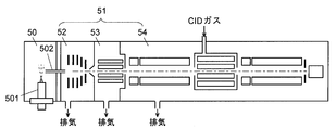
- FIG. 1 shows a schematic configuration of a mass spectrometer having an atmospheric pressure ion source 501.
- This mass spectrometer has an ionization chamber 50 that is at atmospheric pressure, and an analysis chamber 51 that communicates with the ionization chamber 50 via a capillary 502 and is maintained in a vacuum.
- the analysis chamber 51 includes a first intermediate vacuum chamber 52 that is maintained at a low vacuum by a rotary pump, and a second intermediate vacuum chamber 53 and a mass analysis chamber 54 that are maintained at a high vacuum by a turbo molecular pump. It has the structure of the multistage differential exhaust system in which the degree of vacuum is increased stepwise (for example, Patent Document 1).
- the analysis chamber 51 When the mass spectrometer is started, the analysis chamber 51 is open to the atmosphere. Therefore, in order to shift from this state to a state where mass analysis is possible, it is necessary to evacuate the analysis chamber 51 with a vacuum pump until the inside of the analysis chamber 51 reaches a desired degree of vacuum.
- the load on the vacuum pump is larger during the operation of exhausting the analysis chamber 51 in the atmospheric pressure state than during the operation of maintaining the degree of vacuum of the analysis chamber 51 that has reached the desired degree of vacuum. And as the exhausting operation time becomes longer, the life of the vacuum pump becomes shorter and the cost for replacement and repair increases.
- the mass spectrometer has been described as a specific example, but as in the mass spectrometer, the ionization chamber having the atmospheric pressure ion source and the ionization chamber communicated with each other through the capillary, and generated in the ionization chamber.
- ion analyzers such as an ion mobility analyzer equipped with an analysis chamber that analyzes the generated ions under vacuum
- the longer the exhaust operation time with a large load the shorter the life of the vacuum pump, which can be replaced or repaired.
- Such costs increase.
- the problem to be solved by the present invention is an ion having an ionization chamber used at atmospheric pressure, an analysis chamber that communicates with the ionization chamber via a capillary and analyzes ions generated in the ionization chamber under vacuum
- the load of a vacuum pump used for exhausting the analysis chamber is reduced.
- An ion analyzer which has been made to solve the above problems, a) an ionization chamber maintained at atmospheric pressure; b) an analysis chamber for analyzing ions generated in the ionization chamber; c) a vacuum pump for exhausting the inside of the analysis chamber; d) a capillary communicating the ionization chamber and the analysis chamber; e) conductance changing means for changing the conductance of the capillary; and f) a controller for operating the conductance changing means to reduce the conductance of the capillary when the degree of vacuum in the analysis chamber is lower than a predetermined degree of vacuum.
- the ion analyzer includes a conductance changing means for changing the conductance of the capillary and a controller for operating the conductance changing means when the vacuum degree in the analysis chamber is lower than a predetermined vacuum degree. Therefore, for example, when the ion analyzer is started up, the conductance changing means reduces the conductance of the capillary (increases the resistance) to reduce the amount of air flowing from the ionization chamber into the analysis chamber, thereby shortening the time for exhausting the vacuum pump. The load can be reduced.
- the conductance changing means can be embodied based on the following concept. If the capillary inner diameter is D (m), the length is L (m), and the pressure difference between the inlet and outlet ends is P (Pa), the conductance of the capillary (the ease of gas flow with viscosity coefficient ⁇ ) C (m 3 / s) is expressed by the following Knudsen approximation.
- the conductance C decreases as the viscosity coefficient ⁇ of the gas increases.
- the viscosity coefficient ⁇ can be increased 1.6 times and the conductance can be reduced by about 40%.
- a heating mechanism for heating the capillary can be used as the conductance changing means.
- the conductance can be reduced by heating the air flowing through the capillary.
- heating of the capillaries can be stopped to increase conductance, thereby increasing the sample introduction efficiency.
- the ion analyzer when the ion analyzer includes an atmospheric pressure ion source (such as an ESI probe or an APCI probe) that ionizes a liquid sample, from the charged droplet derived from the liquid sample that the atmospheric pressure ion source generally has.
- a heating gas supply mechanism that supplies a heating gas for desorbing solvent molecules into the ionization chamber can also be used as the conductance changing means. Normally, a heated gas is sprayed onto charged droplets only when ionizing a target sample. However, in one aspect of the ion analyzer according to the present invention, this is used at startup.
- a heated gas of 400 ° C is supplied into the ionization chamber, it will be cooled somewhat in the ionization chamber (eg, cooled to 300 ° C), but a gas having a higher viscosity than normal temperature gas will flow from the ionization chamber into the capillary to reduce the conductance. be able to. In this way, the conductance can be changed using existing components.
- the ion analyzer By using the ion analyzer according to the present invention, it is possible to reduce the load of the vacuum pump that exhausts the analysis chamber of the ion analyzer.
- the principal part block diagram of a mass spectrometer The principal part block diagram of the interface part of one Example of the mass spectrometer which concerns on this invention.
- FIG. 2 shows an enlarged view of the front part of the analysis chamber 11 and the operation thereof will be described.
- the mass spectrometer of the present embodiment has an ionization chamber 10 that is substantially atmospheric pressure and an analysis chamber 11 that is evacuated by a vacuum pump.
- the analysis chamber 11 includes a first intermediate vacuum chamber 12, a second intermediate vacuum chamber 13, and a mass analysis chamber (not shown) in order from the side closer to the ionization chamber 10, and the degree of vacuum is gradually increased in this order. It has an enhanced multi-stage differential exhaust system configuration.
- the first intermediate vacuum chamber 12 is evacuated by a rotary pump (RP) 15 and maintained at a low vacuum.
- the ionization chamber 10 is provided with an ESI (electrospray ionization) probe 101 that is an atmospheric pressure ion source for ionizing a liquid sample, and a heated gas supply tube 103.
- the ionization chamber 10 and the first intermediate vacuum chamber 12 communicate with each other through a small diameter capillary 102.
- the liquid sample introduced into the ESI probe 101 is charged and atomized by the nebulizer gas to form fine charged droplets that are sprayed into the ionization chamber 10.
- the charged droplet sprayed in the ionization chamber 10 is drawn into the first intermediate vacuum chamber 12 due to a pressure difference between the ionization chamber 10 that is atmospheric pressure and the first intermediate vacuum chamber 12 that is low vacuum.
- the heated gas supply pipe 103 supplies the heated gas supplied from the heated gas source 104 into the ionization chamber 10, whereby the solvent molecules are desorbed from the charged droplets directed from the ESI probe 101 to the inlet of the capillary 102. Release.
- the first intermediate vacuum chamber 12 and the second intermediate vacuum chamber 13 are separated by a skimmer 22 having a small hole at the top.
- the first intermediate vacuum chamber 12 and the second intermediate vacuum chamber 13 are provided with ion guides 121 and 131 for transporting ions to the subsequent stage while converging ions.
- the second intermediate vacuum chamber 13 and the mass spectrometry chamber (not shown) are maintained at a high vacuum by a turbo molecular pump (TMP) 16.
- TMP turbo molecular pump
- each unit is controlled by the control unit 20.
- the control unit 20 the characteristic control at the time of activation in the present embodiment will be described.
- the ionization chamber 10 and the analysis chamber 11 are open to the atmosphere. Therefore, the inside of the analysis chamber 11 is first evacuated in order to make the mass analysis possible.
- the analysis chamber 11 is exhausted by evacuating the analysis chamber 11 to a low vacuum by a rotary pump 15 connected to the first intermediate vacuum chamber 12, and subsequently the second intermediate vacuum chamber 13 and the mass analysis chamber by a turbo molecular pump 16. This is done by evacuating to a high vacuum.
- the control unit 20 of the mass spectrometer of the present embodiment supplies an inert gas (for example, nitrogen gas) heated to about 400 ° C. from the heated gas source 104 to supply the heated gas.
- the heated gas supplied into the ionization chamber 10 is somewhat cooled in the ionization chamber 10 (for example, cooled to 300 ° C.), but a gas having a viscosity higher than that at room temperature flows into the capillary 102 from the ionization chamber 10. This reduces the conductance.
- the activation of the rotary pump 15 and the start of heating of the capillary 102 do not have to be strictly the same, and there may be a slight time difference.
- the capillary 102 is heated in parallel with the activation of the rotary pump 15, the air near the capillary 102 and the air passing through the capillary 102 are also heated.
- the viscosity coefficient ⁇ increases 1.6 times. From the above equation (1), it can be seen that the conductance decreases by about 0.63 times, and the amount of air flowing from the ionization chamber 10 to the first intermediate vacuum chamber 12 through the capillary 102 decreases.
- the amount of air flowing into the first intermediate vacuum chamber 12 is reduced in this way, and the time for exhausting the analysis chamber 11 is shortened, so the load on the rotary pump 15 is reduced. .
- the second intermediate vacuum chamber 13 and the mass analysis chamber are exhausted by the turbo molecular pump 16. Since the amount of air flowing into the second intermediate vacuum chamber 13 through the chamber 12 is reduced, the time required for the turbo molecular pump 16 to exhaust the second intermediate vacuum chamber 13 and the mass spectrometry chamber to a predetermined degree of vacuum (high vacuum). And the load on the turbo molecular pump 16 is reduced.
- the mass spectrometer of the present embodiment includes the heated gas supply pipe 103 and the heated gas source 104 that are conventionally used when ionizing a liquid sample (that is, used only when analyzing an actual sample). Since the heated gas supply mechanism is used as a conductance changing unit when the mass spectrometer is started, it can be configured at low cost without adding a new special component.
- the mass spectrometer provided with the ESI probe 101 that ionizes a liquid sample at atmospheric pressure is taken as an example, but a mass spectrometer equipped with an APCI probe can also be configured in the same manner as described above.
- the ESI probe 101 and the heating gas supply mechanism are separately provided.
- the heating gas supply pipe is arranged on the outer periphery of the ESI probe 101 and integrally configured. It may be a thing (for example, patent document 2).
- the heated gas supply pipe 103 may not be provided. In such a case, the same effect as described above can be obtained by providing a heating mechanism for heating the capillary 102.
- the heating mechanism may be introduced into a mass spectrometer having a configuration having the heated gas supply tube 103.
- the heating mechanism can be constituted by, for example, a heater 106 wound around the outer periphery of the capillary 102 and a power source 105 that supplies current to the heater 106 as shown in FIG.
- the capillary can be heated using the configuration described in Patent Document 3. In these configurations, it is preferable that the temperature of the capillary 102 can be measured using a temperature sensor.
- FIG. 4 shows the result of measuring the correlation between the temperature of the capillary 102 and the degree of vacuum of the first intermediate vacuum chamber 12 in order to verify the effect obtained by the configuration of the above embodiment.
- FIG. 4 is a graph showing the relative pressure in the first intermediate vacuum chamber 12 at each temperature when the pressure when the temperature of the capillary 102 is 20 ° C. is 100 (%).
- FIG. 4 shows that the pressure in the first vacuum chamber decreases (the degree of vacuum increases) as the temperature of the capillary 102 increases.
- the above embodiment is an example, and can be appropriately changed in accordance with the gist of the present invention.
- the mass spectrometer has been described in the above embodiment, the same configuration as described above can be used in an analyzer such as an ion mobility analyzer that is used by communicating an atmospheric pressure ionization chamber and a vacuum analysis chamber.
- the example in which the capillary 102 is heated at the time of starting the mass spectrometer (an example in which the temperature of the capillary 102 is increased by inflow of heated gas and an example in which the capillary 102 is directly heated) has been described.
- the capillary 102 is heated when a malfunction occurs in the rotary pump 15 or the turbo molecular pump 16 during the analysis and the exhaust capacity is reduced (that is, when the degree of vacuum in the analysis chamber 11 is lower than a predetermined degree of vacuum).
- the amount of air flowing from the ionization chamber 10 into the analysis chamber 11 may be reduced.
- the vacuum degree of the analysis chamber 11 can be prevented from rapidly deteriorating, and a certain degree of vacuum degree can be maintained until the analysis being performed is completed.
- the conductance of the capillary 102 is reduced by heating the capillary 102 and reducing the viscosity coefficient ⁇ of air, but the conductance of the capillary 102 can be reduced by other methods.
- the length L of the capillary 102 is set. The conductance can be reduced by increasing the length.
- the capillary 102 configured to change the inner diameter can be used, and when the degree of vacuum in the analysis chamber 11 is lower than a predetermined degree of vacuum, the inner diameter of the capillary 102 can be reduced to reduce the conductance.
Abstract
Description
a) 大気圧に維持されるイオン化室と、
b) 前記イオン化室において生成したイオンを分析する分析室と、
c) 前記分析室の内部を排気する真空ポンプと、
d) 前記イオン化室と前記分析室を連通するキャピラリと、
e) 前記キャピラリのコンダクタンスを変更するコンダクタンス変更手段と、
f) 前記分析室の真空度が予め決められた真空度よりも低いときに、前記キャピラリのコンダクタンスを小さくするように前記コンダクタンス変更手段を動作させる制御部と
を備えることを特徴とする。
キャピラリの内径をD(m)、長さをL(m)とし、その入口端と出口端の圧力差をP(Pa)とすると、該キャピラリのコンダクタンス(粘性係数ηの気体の流れやすさ)C(m3/s)は以下のKnudsenの近似式で表される。

一方、分析室内が所期の真空度に達し、イオンの分析を行う際には、キャピラリの加熱を停止しコンダクタンスを大きくして試料の導入効率を高めることができる。

101…ESIプローブ
102…キャピラリ
103…加熱ガス送給管
104…加熱ガス源
105…電源
106…ヒータ
107…温度センサ
11…分析室
12…第1中間真空室
121…イオインガイド
13…第2中間真空室
131…イオンガイド
15…ロータリーポンプ
16…ターボ分子ポンプ
20…制御部
Claims (4)
- a) 大気圧に維持されるイオン化室と、
b) 前記イオン化室において生成したイオンを分析する分析室と、
c) 前記分析室の内部を排気する真空ポンプと、
d) 前記イオン化室と前記分析室を連通するキャピラリと、
e) 前記キャピラリのコンダクタンスを変更するコンダクタンス変更手段と、
f) 前記分析室の真空度が予め決められた真空度よりも低いときに、前記キャピラリのコンダクタンスを小さくするように前記コンダクタンス変更手段を動作させる制御部と
を備えることを特徴とするイオン分析装置。 - 前記制御部が、前記分析室を大気圧から所定の真空度まで排気する間、前記キャピラリのコンダクタンスを小さくするように前記コンダクタンス変更手段を動作させることを備えることを特徴とする請求項1に記載のイオン分析装置。
- 前記コンダクタンス変更手段が、前記キャピラリを加熱する加熱機構であることを特徴とする請求項1に記載のイオン分析装置。
- 前記コンダクタンス変更手段が、イオン化室内に加熱ガスを供給する加熱ガス供給機構であることを特徴とする請求項1に記載のイオン分析装置。
Priority Applications (5)
| Application Number | Priority Date | Filing Date | Title |
|---|---|---|---|
| CN201580085406.7A CN108475615A (zh) | 2015-12-17 | 2015-12-17 | 离子分析装置 |
| US16/062,891 US10991565B2 (en) | 2015-12-17 | 2015-12-17 | Ion analyzer |
| JP2017556280A JP6547843B2 (ja) | 2015-12-17 | 2015-12-17 | イオン分析装置 |
| PCT/JP2015/085409 WO2017104053A1 (ja) | 2015-12-17 | 2015-12-17 | イオン分析装置 |
| EP15910743.2A EP3392902A4 (en) | 2015-12-17 | 2015-12-17 | Ion analyzing apparatus |
Applications Claiming Priority (1)
| Application Number | Priority Date | Filing Date | Title |
|---|---|---|---|
| PCT/JP2015/085409 WO2017104053A1 (ja) | 2015-12-17 | 2015-12-17 | イオン分析装置 |
Publications (1)
| Publication Number | Publication Date |
|---|---|
| WO2017104053A1 true WO2017104053A1 (ja) | 2017-06-22 |
Family
ID=59056225
Family Applications (1)
| Application Number | Title | Priority Date | Filing Date |
|---|---|---|---|
| PCT/JP2015/085409 WO2017104053A1 (ja) | 2015-12-17 | 2015-12-17 | イオン分析装置 |
Country Status (5)
| Country | Link |
|---|---|
| US (1) | US10991565B2 (ja) |
| EP (1) | EP3392902A4 (ja) |
| JP (1) | JP6547843B2 (ja) |
| CN (1) | CN108475615A (ja) |
| WO (1) | WO2017104053A1 (ja) |
Cited By (1)
| Publication number | Priority date | Publication date | Assignee | Title |
|---|---|---|---|---|
| WO2023026355A1 (ja) * | 2021-08-24 | 2023-03-02 | 株式会社島津製作所 | イオン化装置 |
Families Citing this family (2)
| Publication number | Priority date | Publication date | Assignee | Title |
|---|---|---|---|---|
| EP3392902A4 (en) * | 2015-12-17 | 2018-12-26 | Shimadzu Corporation | Ion analyzing apparatus |
| GB201808949D0 (en) * | 2018-05-31 | 2018-07-18 | Micromass Ltd | Bench-top time of flight mass spectrometer |
Citations (10)
| Publication number | Priority date | Publication date | Assignee | Title |
|---|---|---|---|---|
| JPS4816426B1 (ja) | 1968-07-13 | 1973-05-22 | ||
| JPH02110859U (ja) * | 1989-02-20 | 1990-09-05 | ||
| JPH08166500A (ja) * | 1994-12-15 | 1996-06-25 | Nikon Corp | 真空保護装置 |
| JP2006208334A (ja) * | 2005-01-31 | 2006-08-10 | Gl Sciences Inc | 微小流量の流体制御方法及び抵抗体 |
| JP2008233073A (ja) * | 2007-02-19 | 2008-10-02 | Yamatake Corp | 流量計および流量制御装置 |
| WO2009031179A1 (ja) * | 2007-09-04 | 2009-03-12 | Shimadzu Corporation | 質量分析装置 |
| US20100301209A1 (en) * | 2007-06-01 | 2010-12-02 | Purdue Research Foundation | Discontinuous atmospheric pressure interface |
| JP2013105737A (ja) * | 2011-11-14 | 2013-05-30 | Laser-Spectra Kk | 顕微レーザー質量分析装置 |
| JP2015049077A (ja) | 2013-08-30 | 2015-03-16 | 株式会社島津製作所 | イオン化プローブ |
| JP2015198014A (ja) | 2014-04-01 | 2015-11-09 | 株式会社島津製作所 | イオン輸送装置及び該装置を用いた質量分析装置 |
Family Cites Families (22)
| Publication number | Priority date | Publication date | Assignee | Title |
|---|---|---|---|---|
| US2610300A (en) * | 1951-08-07 | 1952-09-09 | Wilson W Walton | Flow control |
| US2775707A (en) * | 1955-05-09 | 1956-12-25 | Cons Electrodynamics Corp | Heat compensating device |
| GB1092803A (en) * | 1964-06-03 | 1967-11-29 | Ass Elect Ind | Improvements in or relating to mass spectrometers |
| US4018241A (en) * | 1974-09-23 | 1977-04-19 | The Regents Of The University Of Colorado | Method and inlet control system for controlling a gas flow sample to an evacuated chamber |
| US4201913A (en) * | 1978-10-06 | 1980-05-06 | Honeywell Inc. | Sampling system for mass spectrometer |
| DK1217643T3 (da) * | 2000-12-15 | 2009-01-19 | V & F Analyse & Messtechnik | Fremgangsmåde og indretning til vurdering af tilstanden i organismer og naturprodukter samt til analyse af en gasformig blanding med hoved- og bikomponenter |
| US6622746B2 (en) * | 2001-12-12 | 2003-09-23 | Eastman Kodak Company | Microfluidic system for controlled fluid mixing and delivery |
| US6568799B1 (en) * | 2002-01-23 | 2003-05-27 | Eastman Kodak Company | Drop-on-demand ink jet printer with controlled fluid flow to effect drop ejection |
| FR2856046B1 (fr) * | 2003-06-16 | 2005-07-29 | Biomerieux Sa | Microvanne fluidique a ouverture par commande electrique |
| JP4816426B2 (ja) | 2006-11-22 | 2011-11-16 | 株式会社島津製作所 | 質量分析計 |
| US7564029B2 (en) * | 2007-08-15 | 2009-07-21 | Varian, Inc. | Sample ionization at above-vacuum pressures |
| WO2010039512A1 (en) * | 2008-09-30 | 2010-04-08 | Advion Biosciences, Inc. | Atmospheric pressure ionization (api) interface structures for a mass spectrometer |
| US7915580B2 (en) * | 2008-10-15 | 2011-03-29 | Thermo Finnigan Llc | Electro-dynamic or electro-static lens coupled to a stacked ring ion guide |
| WO2010124019A1 (en) * | 2009-04-21 | 2010-10-28 | Excellims Corporation | Intelligently controlled spectrometer methods and apparatus |
| US8859957B2 (en) * | 2010-02-26 | 2014-10-14 | Purdue Research Foundation | Systems and methods for sample analysis |
| JP5604165B2 (ja) * | 2010-04-19 | 2014-10-08 | 株式会社日立ハイテクノロジーズ | 質量分析装置 |
| JP5497615B2 (ja) * | 2010-11-08 | 2014-05-21 | 株式会社日立ハイテクノロジーズ | 質量分析装置 |
| EP2631930B1 (en) * | 2012-02-21 | 2017-03-29 | Max-Planck-Gesellschaft zur Förderung der Wissenschaften e.V. | Device for transferring ions from high to low pressure atmosphere, system and use |
| JP6025406B2 (ja) * | 2012-06-04 | 2016-11-16 | 株式会社日立ハイテクノロジーズ | 質量分析装置 |
| WO2015195607A1 (en) * | 2014-06-16 | 2015-12-23 | Purdue Research Foundation | Systems and methods for analyzing a sample from a surface |
| FR3024436B1 (fr) * | 2014-07-30 | 2018-01-05 | Safran Aircraft Engines | Systeme et procede de propulsion spatiale |
| EP3392902A4 (en) * | 2015-12-17 | 2018-12-26 | Shimadzu Corporation | Ion analyzing apparatus |
-
2015
- 2015-12-17 EP EP15910743.2A patent/EP3392902A4/en not_active Withdrawn
- 2015-12-17 JP JP2017556280A patent/JP6547843B2/ja active Active
- 2015-12-17 WO PCT/JP2015/085409 patent/WO2017104053A1/ja active Application Filing
- 2015-12-17 US US16/062,891 patent/US10991565B2/en active Active
- 2015-12-17 CN CN201580085406.7A patent/CN108475615A/zh not_active Withdrawn
Patent Citations (10)
| Publication number | Priority date | Publication date | Assignee | Title |
|---|---|---|---|---|
| JPS4816426B1 (ja) | 1968-07-13 | 1973-05-22 | ||
| JPH02110859U (ja) * | 1989-02-20 | 1990-09-05 | ||
| JPH08166500A (ja) * | 1994-12-15 | 1996-06-25 | Nikon Corp | 真空保護装置 |
| JP2006208334A (ja) * | 2005-01-31 | 2006-08-10 | Gl Sciences Inc | 微小流量の流体制御方法及び抵抗体 |
| JP2008233073A (ja) * | 2007-02-19 | 2008-10-02 | Yamatake Corp | 流量計および流量制御装置 |
| US20100301209A1 (en) * | 2007-06-01 | 2010-12-02 | Purdue Research Foundation | Discontinuous atmospheric pressure interface |
| WO2009031179A1 (ja) * | 2007-09-04 | 2009-03-12 | Shimadzu Corporation | 質量分析装置 |
| JP2013105737A (ja) * | 2011-11-14 | 2013-05-30 | Laser-Spectra Kk | 顕微レーザー質量分析装置 |
| JP2015049077A (ja) | 2013-08-30 | 2015-03-16 | 株式会社島津製作所 | イオン化プローブ |
| JP2015198014A (ja) | 2014-04-01 | 2015-11-09 | 株式会社島津製作所 | イオン輸送装置及び該装置を用いた質量分析装置 |
Non-Patent Citations (1)
| Title |
|---|
| See also references of EP3392902A4 |
Cited By (1)
| Publication number | Priority date | Publication date | Assignee | Title |
|---|---|---|---|---|
| WO2023026355A1 (ja) * | 2021-08-24 | 2023-03-02 | 株式会社島津製作所 | イオン化装置 |
Also Published As
| Publication number | Publication date |
|---|---|
| JP6547843B2 (ja) | 2019-07-24 |
| EP3392902A1 (en) | 2018-10-24 |
| US20180374694A1 (en) | 2018-12-27 |
| JPWO2017104053A1 (ja) | 2018-08-02 |
| EP3392902A4 (en) | 2018-12-26 |
| CN108475615A (zh) | 2018-08-31 |
| US10991565B2 (en) | 2021-04-27 |
Similar Documents
| Publication | Publication Date | Title |
|---|---|---|
| RU2769119C2 (ru) | Способ переноса ионов, интерфейс, выполненный с возможностью переноса ионов, и система, содержащая источник газообразных ионов | |
| WO2017104053A1 (ja) | イオン分析装置 | |
| US10229825B2 (en) | Ion transfer tube flow and pumping system load | |
| JP2005127931A (ja) | 昇温脱離ガス分析装置 | |
| JP4752676B2 (ja) | 質量分析装置 | |
| JP2018040794A (ja) | 質量分析のためのイオン輸送装置 | |
| JP5452839B2 (ja) | 分析装置 | |
| WO2003046543A1 (fr) | Spectrometre de masse a ionisation a la pression atmospherique | |
| US11099161B2 (en) | Ionizer and mass spectrometer | |
| JP7047936B2 (ja) | 質量分析装置 | |
| WO2008146333A1 (ja) | 質量分析装置 | |
| EP4322201A1 (en) | Mass spectrometer and method for controlling same | |
| WO2019220552A1 (ja) | ガスクロマトグラフ質量分析装置 | |
| CN113711025A (zh) | 质量分析装置以及质量分析方法 | |
| CN116868306A (zh) | 质谱仪的真空腔室中的压强控制 | |
| WO2017002176A1 (ja) | 真空装置、及び、これを備えた分析装置 | |
| JP2004226353A (ja) | ガスクロマトグラフ質量分析装置 | |
| JP2008241533A (ja) | 試料導入装置および試料導入方法 | |
| JP3978184B2 (ja) | 大気圧イオン化質量分析装置 | |
| CN112088420A (zh) | 飞行时间质谱分析装置 |
Legal Events
| Date | Code | Title | Description |
|---|---|---|---|
| 121 | Ep: the epo has been informed by wipo that ep was designated in this application |
Ref document number: 15910743 Country of ref document: EP Kind code of ref document: A1 |
|
| ENP | Entry into the national phase |
Ref document number: 2017556280 Country of ref document: JP Kind code of ref document: A |
|
| NENP | Non-entry into the national phase |
Ref country code: DE |
|
| WWE | Wipo information: entry into national phase |
Ref document number: 2015910743 Country of ref document: EP |
|
| ENP | Entry into the national phase |
Ref document number: 2015910743 Country of ref document: EP Effective date: 20180717 |