WO2017094570A1 - 電気接続装置 - Google Patents
電気接続装置 Download PDFInfo
- Publication number
- WO2017094570A1 WO2017094570A1 PCT/JP2016/084663 JP2016084663W WO2017094570A1 WO 2017094570 A1 WO2017094570 A1 WO 2017094570A1 JP 2016084663 W JP2016084663 W JP 2016084663W WO 2017094570 A1 WO2017094570 A1 WO 2017094570A1
- Authority
- WO
- WIPO (PCT)
- Prior art keywords
- connector
- fitting
- holding
- electrical connection
- operated
- Prior art date
- Legal status (The legal status is an assumption and is not a legal conclusion. Google has not performed a legal analysis and makes no representation as to the accuracy of the status listed.)
- Ceased
Links
Images

Classifications
-
- H—ELECTRICITY
- H01—ELECTRIC ELEMENTS
- H01R—ELECTRICALLY-CONDUCTIVE CONNECTIONS; STRUCTURAL ASSOCIATIONS OF A PLURALITY OF MUTUALLY-INSULATED ELECTRICAL CONNECTING ELEMENTS; COUPLING DEVICES; CURRENT COLLECTORS
- H01R13/00—Details of coupling devices of the kinds covered by groups H01R12/70 or H01R24/00 - H01R33/00
- H01R13/62—Means for facilitating engagement or disengagement of coupling parts or for holding them in engagement
- H01R13/629—Additional means for facilitating engagement or disengagement of coupling parts, e.g. aligning or guiding means, levers, gas pressure electrical locking indicators, manufacturing tolerances
- H01R13/62905—Additional means for facilitating engagement or disengagement of coupling parts, e.g. aligning or guiding means, levers, gas pressure electrical locking indicators, manufacturing tolerances comprising a camming member
- H01R13/62911—U-shaped sliding element
-
- H—ELECTRICITY
- H01—ELECTRIC ELEMENTS
- H01R—ELECTRICALLY-CONDUCTIVE CONNECTIONS; STRUCTURAL ASSOCIATIONS OF A PLURALITY OF MUTUALLY-INSULATED ELECTRICAL CONNECTING ELEMENTS; COUPLING DEVICES; CURRENT COLLECTORS
- H01R13/00—Details of coupling devices of the kinds covered by groups H01R12/70 or H01R24/00 - H01R33/00
- H01R13/62—Means for facilitating engagement or disengagement of coupling parts or for holding them in engagement
- H01R13/629—Additional means for facilitating engagement or disengagement of coupling parts, e.g. aligning or guiding means, levers, gas pressure electrical locking indicators, manufacturing tolerances
- H01R13/631—Additional means for facilitating engagement or disengagement of coupling parts, e.g. aligning or guiding means, levers, gas pressure electrical locking indicators, manufacturing tolerances for engagement only
-
- H—ELECTRICITY
- H01—ELECTRIC ELEMENTS
- H01R—ELECTRICALLY-CONDUCTIVE CONNECTIONS; STRUCTURAL ASSOCIATIONS OF A PLURALITY OF MUTUALLY-INSULATED ELECTRICAL CONNECTING ELEMENTS; COUPLING DEVICES; CURRENT COLLECTORS
- H01R13/00—Details of coupling devices of the kinds covered by groups H01R12/70 or H01R24/00 - H01R33/00
- H01R13/62—Means for facilitating engagement or disengagement of coupling parts or for holding them in engagement
- H01R13/639—Additional means for holding or locking coupling parts together, after engagement, e.g. separate keylock, retainer strap
Definitions
- the present invention relates to an electrical connection device for performing electrical connection between members coupled to each other so as to be relatively rotatable.
- Each connector includes a connector terminal connected to a predetermined circuit via an electric wire and the like, and a connector housing that holds the connector terminal, and is connected to each connector by fitting the connector terminals of the connectors.
- the connected circuits are electrically connected.
- Patent Document 1 discloses a connector in which an electrical connection device is attached to a vehicle body via a fixing bracket.
- a vehicle body and a door for example, a vehicle body and a door, a vehicle body and a door mirror, a steering shaft and a member that rotatably supports this can be rotated within a predetermined range.
- the fitting is involved.
- one connector In order to enable the relative rotation, one connector must be separated from a member to which the connector is attached and fitted to the other connector. Both the connector disconnecting operation and the connector fitting operation are complicated and must be performed manually. This hinders improvement in work efficiency.
- a first wiring member wired to the first member, and the rotation center axis so that the first member can be rotated relative to the first member about a predetermined rotation center axis.
- An electrical connection device for electrical connection with a second wiring member wired in a second member coupled in a coupling direction along the first member, and connected to the first wiring member;
- a first connector to be fixed, connected to the second wiring member, attached to the second member, and formed into the electrical connection by fitting with the first connector in a specific fitting direction.
- a connector holding member connected to the second connector and the second member, wherein the first connector and the second connector are connected in the fitting direction in a state where the first member and the second member are connected.
- the second connector at a position where it can face each other.
- a connector holding member, and a fitting operation member held by the holding connector selected from the first connector and the second connector so as to be relatively movable in an operation direction intersecting the fitting direction. Prepare.
- the fitting operation member is connected to the holding connector in a state in which the first member and the second member are connected and the first connector and the second connector face each other in the fitting direction.
- the operated connector on the opposite side of the holding connector of the first connector and the second connector is pulled toward the holding connector side along the fitting direction by moving relative to the holding connector.
- a connector operating portion that allows the second connector to be detached from the connector holding member in the fitting direction.
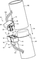
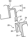
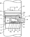
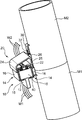
- FIG. 1 is a perspective view showing first and second members according to an embodiment of the present invention and an electrical connection device installed around the first and second members, and a perspective view showing a state before the first and second members are coupled to each other. It is. It is a cross-sectional side view which shows the structure for engagement with the connector holding member and 2nd connector in the said electrical connection apparatus.
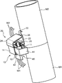
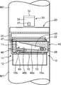
- FIG. 3 is a perspective view showing a state where the first and second members are connected to each other and the first connector and the second connector face each other.
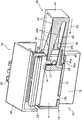
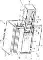
- FIG. 4 is a partial cross-sectional perspective view showing a relative positional relationship between the operation surface of the fitting operation member and the operated portion of the second connector in the state shown in FIG. 3.
- FIG. 3 is a perspective view showing a state where the first and second members are connected to each other and the first connector and the second connector face each other.
- FIG. 4 is a partial cross-sectional perspective view showing a relative positional relationship between the operation surface of the fitting operation member and the operated portion of the second connector in the state shown
- FIG. 5 is a cross-sectional front view showing a state in which the fitting operation member is operated from the state shown in FIG. 4 to a position where an operation surface of the fitting operation member comes into contact with the operated portion.
- FIG. 6 is a perspective view showing a state where the operation of the fitting operation member further proceeds from the state shown in FIG. 5 and the fitting between the first connector and the second connector is completed.
- It is a cross-sectional front view which shows the state shown by FIG. The operation surface of the fitting operation member and the operated portion of the second connector in a state corresponding to the state shown in FIG. 4 and in a state where the operated portion is at a higher position than the position shown in FIG.
- FIG. 9 is a cross-sectional front view showing a state in which the fitting operation member is operated from the state shown in FIG. 8 to a position where the operation surface of the fitting operation member comes into contact with the operated portion.
- the electrical connection device can be rotated relative to the plurality of first wiring members W1 wired to the first member M1 within a predetermined range with respect to the first member M1.
- the first connector 10, the second connector 20, and the connector holding member are for electrical connection between the second wiring members W2 wired to the second member M2 coupled to the first member M2. 30 and a fitting operation member 40.
- the first member M1 has a columnar shape or a cylindrical shape extending in the vertical direction, and an upper end portion thereof constitutes a fitting portion 2 having a cylindrical outer peripheral surface whose diameter is smaller than that of other portions.
- the second member M2 has a cylindrical shape or a columnar shape having a lower end into which the insertion portion 2 can be inserted.
- first member M1 is disposed on the lower side and the second member M2 is disposed on the upper side, but the arrangement of the first and second members according to the present invention is not limited. Further, the shapes of the first and second members are not limited.
- the first connector 10 is connected to the terminals of the plurality of first wiring members W1.
- the plurality of first wiring members W1 are routed along the outer peripheral surface of the first member M1.
- the first connector 10 includes a plurality of connector terminals (male connector terminals in this embodiment) and a connector housing 12 which are not shown.
- the plurality of connector terminals are connected to respective terminals of the plurality of first wiring members W1.
- the connector housing 12 holds the rear portion of each connector terminal leaving the tip portion (male electrical contact portion).
- the connector housing 12 includes a hood 11 that surrounds the distal end portion of each connector terminal, and the hood 11 faces upward (that is, faces the second member M2). In this embodiment, it is fixed on the outer peripheral surface in the vicinity of the fitting portion 2.
- the fixing of the first connector 10 to the first member M1 may be performed in a state where both are in direct contact, or by the connection of the first connector 10 to the first member M1 via a bracket or the like. It may be done.
- the first connector 10 functions as a holding connector that holds the fitting operation member 40.
- the first connector 10 includes a pair of fitting operation member holding portions 14 formed integrally with the connector housing 12 in addition to the connector housing 12.
- the fitting operation member 40 and the fitting operation member holding part 14 will be described in detail later.
- the second connector 20 is connected to the terminals of the plurality of second wiring members W2.
- the plurality of second wiring members W2 are routed along, for example, the outer peripheral surface of the second member M1, similarly to the first wiring member W1.
- the second connector 20 has a plurality of connector terminals (in this embodiment, female connector terminals), a connector housing 22, a cover 24, and a held portion 26, which are not shown.
- the plurality of connector terminals are connected to respective terminals of the plurality of second wiring members W2.
- the connector housing 22 holds the connector terminals so that the female electrical contact portion at the tip of each connector terminal is opened to the outside.
- the connector housing 22 has an outer shape that can be fitted inside the hood 11 of the connector housing 12, and with the fitting, the connector terminal held by the connector housing 12 and the connector housing 22 The held connector terminals are fitted to each other to form an electrical connection between the first wiring member W1 and the second wiring member W2. That is, the first connector 10 and the second connector are fitted to each other along the fitting direction parallel to the direction in which the connector housing 22 is inserted into the hood 11, thereby the first wiring member W1 and the first connector. 2. Electrical connection with the wiring material W2 is enabled.
- the fitting direction is a vertical direction, that is, a direction parallel to the rotation center axis.
- the connector housing 22 has an attachment position, specifically a first position where the connector housing 12 can be opposed to the connector housing 12 in the fitting direction when the first member M1 and the second member M2 are connected.
- the second member M2 is attached to the second member M2 via the connector holding member 30 at a position on the outer peripheral surface of the lower end portion of the two members M2.
- the first connector and the second connector face each other in the fitting direction means that, as described above, the first connector and the second connector are separated from each other in the fitting direction. Both the opposing state and the provisional fitting state in which a part of the first connector and the second connector overlap in the fitting direction are included.
- “opposing each other” means that the upper end of the hood 11 of the first connector 10 and the lower end of the connector housing 22 of the second connector 20 overlap as shown in FIGS. 3 and 4. This means a state in which the connector housing 22 is shallowly fitted in the hood 11.
- the cover 24 has a shape that covers the connector housing 22 from above.
- the cover 24 has a back surface 25 that faces the outer peripheral surface of the second member M ⁇ b> 2, and the held portion 26 is formed on the back surface 25.
- the held portion 26 is a portion that is held by the connector holding member 30.
- the connector holding member 30 holds the held portion 26 of the second connector 20 so that the second connector 20 is positioned at the attachment position by being fixed to the second member M2, and the second connector 20 has a function of allowing the held portion 26 to be detached from the connector holding member 30 in the fitting direction by applying an external force in the fitting direction, that is, a downward external force.
- the connector holding member 30 has a tongue-like shape protruding downward from the outer peripheral surface of the second member M2.
- the connector holding member 30 includes a base portion 32 that protrudes radially outward from the outer peripheral surface of the second member M2, and a holding portion that extends downward from the outer end of the base portion 32. 34, and a retaining hole 37 is formed in the lower end portion of the holding portion 34 so as to penetrate the holding portion 34 in the radial direction.
- the connector holding member according to the present invention is formed as a member independent of the second member, and may be joined to the second member by welding or other means. It may be formed integrally, that is, so as to constitute a single member together with the second member.
- the held portion 26 has a box shape that defines an insertion space together with the back surface 25 of the cover 24.
- the insertion space is a space opened up and down and has a shape that allows the holding portion 34 to be inserted into the insertion space through the upper end thereof.
- the held portion 26 has a locked protrusion 27 that partially protrudes into the insertion space, and the locking hole of the holding portion 34 into which the locked protrusion 27 is inserted into the insertion space.
- the held portion 26 is held by the holding portion 34 by being fitted into 37. Furthermore, when a certain amount or more of downward external force is applied to the second connector 20 including the held portion 26 from this state, the locked protrusion 27 is moved downward from the locking hole 37.
- the held part 26 can be detached from the holding part 34 by being detached.
- the fitting operation member 40 has an operation direction (this direction intersecting with the fitting direction (vertical direction in this embodiment)) by the fitting operation member holding portion 14 of the first connector 10 which is the holding connector.
- the direction can be relatively moved in a direction orthogonal to the fitting direction and in a horizontal direction orthogonal to the radial direction of the first and second members M1 and M2.
- the fitting operation member 40 has a connector operation portion, and the connector operation portion is in a state where the first and second connectors 10 and 20 face each other in the fitting direction as described above (in this embodiment, In the temporary fitting state shown in FIGS.
- the fitting operation member 40 is operated so as to move relative to the first connector 10 in the operation direction, so that it is opposite to the holding connector.
- Side operated connector (second connector 20 in this embodiment) is drawn toward the first connector 10 side (lower side in this embodiment) along the fitting direction, and the first connector and the second connector. And the second connector 20 is detached from the connector holding member 30 in the detaching direction.
- the fitting operation member 40 has a pair of side walls 42 and an end wall 44 integrally.
- the pair of side walls 42 are arranged in an operation width direction (a depth direction in FIG. 4) that is a horizontal direction orthogonal to the operation direction in an upright posture parallel to each other, and the end walls 44 are arranged in the pair of the operation directions.
- One end of the side wall 42 (the rear end in the operation direction; the right end in FIG. 4) is connected to the operation width direction.
- the fitting operation member 40 is mounted on the connector housing 12 so as to sandwich the hood 11 of the first connector 10 from both sides in the arrangement direction. In this mounted state, the operation direction ( It is possible to make a relative movement in the left-right direction in FIG.
- each fitting operation member holding portion 14 has a shape for holding the side walls 42 so as to be held at the outer positions.
- each fitting operation member holding portion 14 integrally includes a bottom wall 15 and an outer wall 16.
- the bottom wall 15 supports the side wall 42 at a position below the corresponding side wall 42.
- the outer wall 16 extends upward from the outer end of the bottom wall 15 so as to sandwich the side wall 42 between the outer wall 16 and the outer surface of the hood 11. That is, the fitting operation member holding part 14 allows the side walls 42 of the fitting operation member 40 to slide in the operation direction along the outer surface of the hood 11.
- the side wall 42 is held at a position outside thereof.
- the fitting operation member holding portion 14 moves the fitting operation member 40 into an operation start position as shown in FIGS. 3 and 4 and an operation end position as shown in FIGS. It has a function of being detachably locked at a downstream position (left position in FIG. 4).
- the fitting operation member 40 has a function capable of being detachably locked at each of the operation start position and the operation end position.
- a flexure piece 45 that can be deflected upward is formed at the lower end of the front side portion (left side portion in FIG. 4) of the operation direction in the side wall 42, and a free end portion of the flexure piece 45 is formed.
- a locked protrusion 45a protruding downward is formed.
- the fitting operation member 40 is in the operation start position and the operation end position on the bottom wall 15 of the fitting operation member holding portion 14, the engagement protrusion 45a is fitted.
- a first locking hole 15a and a second locking hole 15b are formed.
- the second connector 20 which is the operated connector has a pair of operated portions 28.
- Each operated portion 28 protrudes outward in the operation width direction from a pair of side surfaces facing the operation width direction (horizontal direction orthogonal to the operation direction; depth direction in FIG. 4) of the side surfaces of the connector housing 22. To do.
- the position of each operated portion 28 is a position close to the lower end of each connector housing 22 and a position close to the end wall 44 of the fitting operation member 40 held by the fitting operation member holding portion 14 (FIG. 4). Is set to the right).
- each insertion groove 13 has a shape that accepts the insertion of the operated portion 28 from above when the connector housing 22 of the second connector 20 is inserted into the inside of the hood 11, specifically, downward from the upper end of the hood 11.
- a shape extending to The insertion of the operated portion 28 into the insertion groove 13 allows the connector housing 22 to be inserted into the hood 11 while avoiding interference between the operated portion 28 and the hood 11.
- the protruding dimension of each operated portion 28 is such that the end of the operated portion 28 protrudes further outward from the outer surface of the hood 11 in a state where the operated portion 28 is inserted in the insertion groove 13. It is set to be.
- the connector operating portion of the fitting operation member 40 comes into contact with the operated portion 28 as the fitting operation member 40 moves in the operating direction, forcing the operated portion 28 in the fitting direction. This is the part to be displaced (pressed down in this embodiment).
- each side wall 42 of the fitting operation member 40 is recessed outward from the other inner side surface and protrudes further outward than the hood 11.
- An operation groove 46 for receiving the end portion) is formed, and an operation surface constituting the connector operation portion is formed by a recess of the operation groove 46.
- the operation groove 46 has an insertion port 47 and a main body groove 48.
- the insertion port 47 is formed at a position for receiving insertion of the operated portion 28 from above in a state where the fitting operation member 40 is at the operation start position. Specifically, the insertion port 47 is formed at a position near the front end (the left end in FIG. 4) in the operation direction of each side wall 42 and at the upper end position of the side wall 42, and opens upward. Yes.
- the body groove 48 extends from a start end (end on the front side in the operation direction; left end in FIG. 4) located in the lower side of the insertion port 47 in a direction opposite to the operation direction (right direction in FIG. 4) and a terminal end (operation direction). It has a shape in which the width in the vertical direction becomes narrower toward the rear end (right end in FIG. 4).
- the vertical width of the starting end of the main body groove 48 is set to a dimension sufficiently larger than the diameter of the operated portion 48.
- the upper and lower ends of the main body groove 48 are defined by an upper end surface 48a and a lower end surface 48b, respectively.
- the upper and lower end surfaces 48a, 48b are both inclined (to the operation direction) so as to become lower toward the rear end (right end in FIG. 4) of the side wall 42 in the operation direction.
- the inclination angle of the upper end surface 48a is larger than that of the lower end surface 48b, and the vertical width of the main body groove 48 becomes narrower toward the rear end in the operation direction by the difference of the inclination angle.
- the operation surface of the fitting operation member 40 is constituted by the upper end surface 48 a of the main body groove 48. That is, the upper end surface 48a abuts against the operated portion 28 in the process in which the fitting operation member 40 is operated in the operation direction from the operation start position (FIG. 5), and further fitting is performed from that position.
- the operated portion 28 and the entire second connector 20 including the operated portion 28 are pushed down.
- the position and inclination angle of the upper end surface 48a are set so that the upper end surface 48a functions in this way.
- first and second connectors 10 and 20 are installed on the first member M1 and the second member M2, respectively.
- the plurality of first wiring members W1 are wired around the first member M1 in a state where the first connector 10 is connected to the terminals of the plurality of first wiring members W1. Further, the first connector 10 is fixed at a regular fixed position as shown in FIG. 1 or the like, that is, at a position on the outer peripheral surface of the first member M1 in the vicinity of the upper end of the first member M1.
- the plurality of second wiring members W2 are wired around the second member M2 in a state where the second connector 20 is connected to the terminals of the plurality of second wiring members W2. Further, the connector holding member 30 is placed at a normal mounting position as shown in FIG. 1 or the like, that is, at a position on the outer peripheral surface of the second member M2 in the vicinity of the lower end of the second member M2. Mounted through.
- the holding portion 34 is 2
- the second connector 20 is set so as to be inserted into the insertion space inside the held portion 26 of the connector 20, and the locked projection 27 of the held portion 26 is inserted into the locking hole 37 of the holding portion 34.
- the held portion 26 is held by the holding portion 34 by fitting.
- the fitting operation member 40 is held at the operation start position shown in FIGS. 1, 3 and 4 with respect to the first connector 10 which is a holding connector. Specifically, the fitting operation member 40 has the engagement protrusion 45 a fitted into the first locking hole 15 a of the bottom wall 15 of the fitting operation member holding portion 14. The insertion port 47 is locked at a position that matches the insertion groove 13 of the hood 11.
- the relative angle of the second member M2 with respect to the first member M1 (the angle in the direction of rotation) is such that the second connector 20 faces the first connector 10 in the fitting direction. It is set as follows. In this embodiment, as shown in FIGS. 3 and 4, the hood 11 of the connector housing 12 of the first connector 10 is coupled with the connection in the direction along the central axis of the first and second members M1 and M2. So that the lower portion of the connector housing 22 of the second connector 20 is shallowly inserted therein, that is, the first and second connectors 10 and 20 are temporarily fitted in a fitting direction parallel to the connecting direction. In addition, the relative angle of the second member M2 with respect to the first member M1 is determined.
- the operated portion 28 of the second connector 20 protrudes from the side surface of the connector housing 22 in the operation width direction.
- the insertion groove 13 formed in the insertion portion 47 enters the start end side portion (the left side portion in FIG. 4) of the operation groove 46 through the insertion port 47 of the fitting operation member 40, thereby Interference with the hood 11 and the fitting operation member 40 can be avoided.
- the insertion groove 13 and the insertion port 47 allow the connector housing 20 to be temporarily fitted to the hood 11 regardless of the protrusion of the operated portion 28 from the connector housing 20.
- the fitting operation member 40 is further provided. Is operated in the operation direction (the direction indicated by the arrow Dp in FIG. 4) from the operation start position to the operation completion position shown in FIG. 7, that is, relative to the first connector 10 in the operation direction.
- the main fitting of the first connector 10 and the second connector 20 (specifically, the normal fitting of the connector terminal not shown in the first connector 10 and the connector terminal not shown in the second connector 20)
- the second connector 20 is detached from the connector holding member 30 at the same time.
- the upper end surface 48a of the operation groove 46 of the fitting operation member 40 As shown in FIG. 5, between the fitting operation member 40 and the fitting completion position.
- the operation surface that inclines so as to become lower as it advances in the operation direction abuts against the operated portion 28 obliquely from above, and the fitting operation member 40 is further operated from this state to the fitting completion position.
- the upper end surface 48a (operation surface) pushes down the operated portion 28 and thus the entire second connector 20 including this. Due to the pushing-down force, the engagement between the latching protrusion 27 of the held portion 26 included in the second connector 20 and the locking hole 37 of the connector holding member 30 is released, and the second connector 20 is detached from the connector holding member 30. While the connector 20 is detached downward, the vertical fitting (fitting direction) of the second connector 20 and the first connector 10 is realized.
- the first and second connectors 10 and 10 can be simply operated by simply moving the fitting operation member 40 from the operation start position to the operation completion position in the operation direction. Both the fitting of the two members 20 and the detachment of the second connector 20 from the connector holding member 30 are achieved.
- the second connector 20 is detached from the connector holding member 30 even though the first and second connectors 10 and 20 are engaged with each other, the second member M2 is predetermined with respect to the first member M1. Within the range (in this embodiment, within the range allowed by the extra length of the second wiring member W2).
- the apparatus according to the present embodiment pushes down the operated portion 28 by abutting the operated portion (the upper end surface 48a of the operating groove 46) inclined with respect to the operating direction and the operated portion 28 (in other words, Therefore, when the connection between the first and second members M1 and M2 is completed, there is some variation in the position of the operated portion 28 in the connecting direction.
- the fitting between the first and second connectors 10 and 20 and the detachment of the second connector 20 from the connector holding member 30 can be achieved.
- the operated portion 28 is located at the position shown in FIG. 8, that is, shown in FIG. 4, at the stage of completion of the connection of the first and second members M1, M2. Even when the position remains above the position to be operated, the fitting operation member 40 is operated in the operation direction from this state, and the timing corresponding to the position of the operated portion 28 (shown in FIG. 4).
- the operation surface comes into contact with the operated portion 28 at a timing earlier than the case where the operated portion 28 can be moved in the fitting direction by further operation from that position. .
- the variation in the position of the operated portion 28 in the fitting direction can be absorbed by the shift in timing at which the upper end surface 48 a contacts the operated portion 28.
- the present invention is not limited to the embodiment described above.
- the present invention includes, for example, the following embodiments.
- the fitting direction of a 1st connector and a 2nd connector is not limited to the direction parallel to the rotation central axis of a 1st and 2nd member.
- the fitting direction is a direction along the direction of relative rotation of the first and second members (for example, in the embodiment, the tangential direction of the outer peripheral surfaces of the first and second members M1 and M2 or close thereto) Direction).
- the fitting direction of the first and second connectors is a direction parallel to the rotation center axis when connecting the first member and the second member.
- the operation direction of a fitting operation member should just be a direction which cross
- the smaller the component in the fitting direction included in the operation direction the greater the function as a booster mechanism that reduces the operating force required for fitting.
- the first connector 10 is a holding connector that holds the fitting operation member 40
- the second connector 20 is operated by the fitting operation member 40
- the second connector may be a holding connector that holds the fitting operation member
- the first connector may be an operated connector that is operated by the fitting operation member.
- the actual movement of the fitting operation member is not only the relative movement in the operation direction with respect to the second connector, but also the movement in the fitting direction toward the first connector (in other words, the connector
- the operation of the fitting operation member becomes complicated by the combined movement including the movement in which the second connector is detached from the holding member in the separation direction.
- the first connector fixed to the first member is a holding connector
- the actual movement of the fitting operation member is a simple movement including only the operation direction. There is an advantage that the operation of the member becomes easier.
- an electrical connection device capable of efficiently performing electrical connection between members coupled to each other so that relative rotation is possible.
- a first wiring member wired to the first member, and the rotation center axis so that the first member can be rotated relative to the first member about a predetermined rotation center axis.
- An electrical connection device for electrical connection with a second wiring member wired in a second member coupled in a coupling direction along the first member, and connected to the first wiring member;
- a first connector to be fixed, connected to the second wiring member, attached to the second member, and formed into the electrical connection by fitting with the first connector in a specific fitting direction.
- a connector holding member connected to the second connector and the second member, wherein the first connector and the second connector are connected in the fitting direction in a state where the first member and the second member are connected.
- the second connector at a position where it can face each other.
- a connector holding member, and a fitting operation member held by the holding connector selected from the first connector and the second connector so as to be relatively movable in an operation direction intersecting the fitting direction. Prepare.
- the fitting operation member is connected to the holding connector in a state in which the first member and the second member are connected and the first connector and the second connector face each other in the fitting direction.
- the operated connector on the opposite side of the holding connector of the first connector and the second connector is pulled toward the holding connector side along the fitting direction by moving relative to the holding connector.
- a connector operating portion that allows the second connector to be detached from the connector holding member in the fitting direction.
- the first member and the second member are coupled to each other in the coupling direction, and the first connector and the second connector are opposed to each other in the fitting direction.
- the first connector and the second connector can be simply operated by simply moving the fitting operation member held by the holding connector, which is one of the connectors, relative to the holding connector in the operation direction crossing the fitting direction.
- the fitting of each other and the removal of the second connector from the connector holding member can be performed simultaneously. That is, only by a simple operation of the fitting operation member, the electrical connection by fitting the first and second connectors and the relative relationship between the first member and the second member by detaching the second connector from the connector holding member. Both permissible rotations can be realized at the same time.
- the fitting direction is a direction parallel to the rotation center axis. This facilitates the work of aligning the first connector and the second connector when the first member and the second member are connected, that is, the work of making the two connectors face each other in the fitting direction.
- the operated connector has an operated portion that receives an operation by the connector operating portion, and the connector operating portion is moved along with the relative movement of the fitting operation member in the operation direction with respect to the holding connector. It is preferable to include an operation surface that is in contact with the operated portion and is inclined with respect to the operating direction so as to draw the operated portion toward the holding connector.
- the operation surface can absorb the variation in the position of the operated portion and can realize the fitting between the first and second connectors and the detachment of the second connector from the connector holding member.
- the holding connector may be either the first connector or the second connector, but the first connector fixed to the first member is the holding connector, that is, the fitting operation in the operation direction.
- a connector that holds the fitting operation member so as to allow relative movement of the member is preferable. This means that compared to the case where the second connector that must be detached from the connector holding member is a holding connector, the actual movement of the fitting operation member is a simple movement whose direction matches the operation direction. Thereby, the operation of the fitting operation member can be made easier.
Landscapes
- Details Of Connecting Devices For Male And Female Coupling (AREA)
Priority Applications (2)
| Application Number | Priority Date | Filing Date | Title |
|---|---|---|---|
| CN201680069760.5A CN108292819B (zh) | 2015-12-03 | 2016-11-22 | 电气连接装置 |
| US15/780,252 US10333251B2 (en) | 2015-12-03 | 2016-11-22 | Electrical connection device |
Applications Claiming Priority (2)
| Application Number | Priority Date | Filing Date | Title |
|---|---|---|---|
| JP2015-236502 | 2015-12-03 | ||
| JP2015236502A JP6500761B2 (ja) | 2015-12-03 | 2015-12-03 | 電気接続装置 |
Publications (1)
| Publication Number | Publication Date |
|---|---|
| WO2017094570A1 true WO2017094570A1 (ja) | 2017-06-08 |
Family
ID=58797209
Family Applications (1)
| Application Number | Title | Priority Date | Filing Date |
|---|---|---|---|
| PCT/JP2016/084663 Ceased WO2017094570A1 (ja) | 2015-12-03 | 2016-11-22 | 電気接続装置 |
Country Status (4)
| Country | Link |
|---|---|
| US (1) | US10333251B2 (enExample) |
| JP (1) | JP6500761B2 (enExample) |
| CN (1) | CN108292819B (enExample) |
| WO (1) | WO2017094570A1 (enExample) |
Families Citing this family (2)
| Publication number | Priority date | Publication date | Assignee | Title |
|---|---|---|---|---|
| JP6913278B2 (ja) * | 2017-02-10 | 2021-08-04 | 株式会社オートネットワーク技術研究所 | 板状導電部材の接続構造及び板状導電路 |
| FR3107997B1 (fr) * | 2020-03-09 | 2022-02-18 | Radiall Sa | Connecteur à pièce d’interface montée en rotation dans le boitier et actionnable par outil pour le coulissement d’un capot de verrouillage à un connecteur complémentaire. |
Citations (2)
| Publication number | Priority date | Publication date | Assignee | Title |
|---|---|---|---|---|
| JPH02182586A (ja) * | 1989-01-10 | 1990-07-17 | Nissan Motor Co Ltd | 車体構造 |
| JPH07240255A (ja) * | 1994-02-25 | 1995-09-12 | Amp Japan Ltd | カム部材付きコネクタ |
Family Cites Families (12)
| Publication number | Priority date | Publication date | Assignee | Title |
|---|---|---|---|---|
| US3577116A (en) * | 1968-08-08 | 1971-05-04 | Molex Inc | Lamp socket and terminal |
| JPH0737667A (ja) * | 1993-07-22 | 1995-02-07 | Alps Electric Co Ltd | ケーブルリール |
| JPH0734593U (ja) * | 1993-12-03 | 1995-06-23 | 株式会社東海理化電機製作所 | 一体成形されたロック機構を有するロールコネクタ |
| JPH0963733A (ja) * | 1995-08-30 | 1997-03-07 | Yazaki Corp | 電気的接続装置用ロック機構 |
| US5892659A (en) * | 1995-12-12 | 1999-04-06 | The Whitaker Corporation | Retention system for solenoid coils |
| US6699070B1 (en) * | 2002-08-08 | 2004-03-02 | Hon Hai Precision Ind. Co., Ltd. | Electrical connector having means for securely mounting the connector to an edge of a printed circuit board |
| JP2005190806A (ja) * | 2003-12-25 | 2005-07-14 | Sumitomo Wiring Syst Ltd | コネクタおよびコネクタ装置 |
| JP4252603B2 (ja) * | 2007-01-31 | 2009-04-08 | タイコエレクトロニクスアンプ株式会社 | 電気コネクタ |
| SG146465A1 (en) * | 2007-03-15 | 2008-10-30 | J S T Mfg Co Ltd | Electric connector |
| JP5105194B2 (ja) * | 2008-11-04 | 2012-12-19 | 住友電装株式会社 | 基板用コネクタ |
| FR2973170B1 (fr) * | 2011-03-23 | 2013-04-05 | Radiall Sa | Connecteur multicontacts a monter sur un panneau |
| JP2014017135A (ja) * | 2012-07-10 | 2014-01-30 | Tyco Electronics Japan Kk | コネクタ |
-
2015
- 2015-12-03 JP JP2015236502A patent/JP6500761B2/ja not_active Expired - Fee Related
-
2016
- 2016-11-22 US US15/780,252 patent/US10333251B2/en not_active Expired - Fee Related
- 2016-11-22 CN CN201680069760.5A patent/CN108292819B/zh not_active Expired - Fee Related
- 2016-11-22 WO PCT/JP2016/084663 patent/WO2017094570A1/ja not_active Ceased
Patent Citations (2)
| Publication number | Priority date | Publication date | Assignee | Title |
|---|---|---|---|---|
| JPH02182586A (ja) * | 1989-01-10 | 1990-07-17 | Nissan Motor Co Ltd | 車体構造 |
| JPH07240255A (ja) * | 1994-02-25 | 1995-09-12 | Amp Japan Ltd | カム部材付きコネクタ |
Also Published As
| Publication number | Publication date |
|---|---|
| CN108292819A (zh) | 2018-07-17 |
| US20180358747A1 (en) | 2018-12-13 |
| US10333251B2 (en) | 2019-06-25 |
| CN108292819B (zh) | 2019-09-13 |
| JP2017103144A (ja) | 2017-06-08 |
| JP6500761B2 (ja) | 2019-04-17 |
Similar Documents
| Publication | Publication Date | Title |
|---|---|---|
| JP4688113B2 (ja) | コネクタ位置保証装置を有するレバー嵌合型コネクタ組立体 | |
| JP5088811B2 (ja) | 電気接続箱 | |
| JP6254542B2 (ja) | ケーブルコネクタを有するコネクタ装置 | |
| JP6288125B2 (ja) | コネクタ | |
| JP4754569B2 (ja) | コネクタ要素のためのキャップ係止手段および該キャップ係止手段が設けられたコネクタ | |
| WO2014115349A1 (ja) | レバー式コネクタ | |
| EP2276122A1 (en) | Lever-type connector | |
| US7445475B2 (en) | Lever type connector | |
| US20170117666A1 (en) | Connector with alignment function | |
| JP6447744B2 (ja) | コネクタ装置 | |
| WO2017094570A1 (ja) | 電気接続装置 | |
| JP3961228B2 (ja) | レバー嵌合式コネクタ | |
| CN100588043C (zh) | 屏蔽连接器、配合屏蔽连接器及屏蔽连接器组件 | |
| WO2019124027A1 (ja) | レバー式コネクタ | |
| WO2016060131A1 (ja) | コネクタ | |
| JP5618748B2 (ja) | コネクタ | |
| JP2010108872A (ja) | レバー式コネクタ | |
| JP4788626B2 (ja) | ランプソケット装置およびそれを備えた照明器具 | |
| JP2008146941A (ja) | コネクタ装置 | |
| JP6064194B2 (ja) | コネクタの嵌合状態の確認が容易なコネクタ装置 | |
| JP6810648B2 (ja) | 端子抜き治具およびコネクタ | |
| JP5000561B2 (ja) | 車両用電気接続装置 | |
| JP2009048890A (ja) | 分割式コネクタ | |
| JP6861464B2 (ja) | レバー式コネクタ | |
| JP2005302581A (ja) | コネクタ接続構造 |
Legal Events
| Date | Code | Title | Description |
|---|---|---|---|
| 121 | Ep: the epo has been informed by wipo that ep was designated in this application |
Ref document number: 16870507 Country of ref document: EP Kind code of ref document: A1 |
|
| NENP | Non-entry into the national phase |
Ref country code: DE |
|
| 122 | Ep: pct application non-entry in european phase |
Ref document number: 16870507 Country of ref document: EP Kind code of ref document: A1 |