WO2017094570A1 - Electrical connection apparatus - Google Patents
Electrical connection apparatus Download PDFInfo
- Publication number
- WO2017094570A1 WO2017094570A1 PCT/JP2016/084663 JP2016084663W WO2017094570A1 WO 2017094570 A1 WO2017094570 A1 WO 2017094570A1 JP 2016084663 W JP2016084663 W JP 2016084663W WO 2017094570 A1 WO2017094570 A1 WO 2017094570A1
- Authority
- WO
- WIPO (PCT)
- Prior art keywords
- connector
- fitting
- holding
- electrical connection
- operated
- Prior art date
Links
Images

Classifications
-
- H—ELECTRICITY
- H01—ELECTRIC ELEMENTS
- H01R—ELECTRICALLY-CONDUCTIVE CONNECTIONS; STRUCTURAL ASSOCIATIONS OF A PLURALITY OF MUTUALLY-INSULATED ELECTRICAL CONNECTING ELEMENTS; COUPLING DEVICES; CURRENT COLLECTORS
- H01R13/00—Details of coupling devices of the kinds covered by groups H01R12/70 or H01R24/00 - H01R33/00
- H01R13/62—Means for facilitating engagement or disengagement of coupling parts or for holding them in engagement
- H01R13/629—Additional means for facilitating engagement or disengagement of coupling parts, e.g. aligning or guiding means, levers, gas pressure electrical locking indicators, manufacturing tolerances
- H01R13/62905—Additional means for facilitating engagement or disengagement of coupling parts, e.g. aligning or guiding means, levers, gas pressure electrical locking indicators, manufacturing tolerances comprising a camming member
- H01R13/62911—U-shaped sliding element
-
- H—ELECTRICITY
- H01—ELECTRIC ELEMENTS
- H01R—ELECTRICALLY-CONDUCTIVE CONNECTIONS; STRUCTURAL ASSOCIATIONS OF A PLURALITY OF MUTUALLY-INSULATED ELECTRICAL CONNECTING ELEMENTS; COUPLING DEVICES; CURRENT COLLECTORS
- H01R13/00—Details of coupling devices of the kinds covered by groups H01R12/70 or H01R24/00 - H01R33/00
- H01R13/62—Means for facilitating engagement or disengagement of coupling parts or for holding them in engagement
- H01R13/629—Additional means for facilitating engagement or disengagement of coupling parts, e.g. aligning or guiding means, levers, gas pressure electrical locking indicators, manufacturing tolerances
- H01R13/631—Additional means for facilitating engagement or disengagement of coupling parts, e.g. aligning or guiding means, levers, gas pressure electrical locking indicators, manufacturing tolerances for engagement only
-
- H—ELECTRICITY
- H01—ELECTRIC ELEMENTS
- H01R—ELECTRICALLY-CONDUCTIVE CONNECTIONS; STRUCTURAL ASSOCIATIONS OF A PLURALITY OF MUTUALLY-INSULATED ELECTRICAL CONNECTING ELEMENTS; COUPLING DEVICES; CURRENT COLLECTORS
- H01R13/00—Details of coupling devices of the kinds covered by groups H01R12/70 or H01R24/00 - H01R33/00
- H01R13/62—Means for facilitating engagement or disengagement of coupling parts or for holding them in engagement
- H01R13/639—Additional means for holding or locking coupling parts together, after engagement, e.g. separate keylock, retainer strap
Definitions
- the present invention relates to an electrical connection device for performing electrical connection between members coupled to each other so as to be relatively rotatable.
- Each connector includes a connector terminal connected to a predetermined circuit via an electric wire and the like, and a connector housing that holds the connector terminal, and is connected to each connector by fitting the connector terminals of the connectors.
- the connected circuits are electrically connected.
- Patent Document 1 discloses a connector in which an electrical connection device is attached to a vehicle body via a fixing bracket.
- a vehicle body and a door for example, a vehicle body and a door, a vehicle body and a door mirror, a steering shaft and a member that rotatably supports this can be rotated within a predetermined range.
- the fitting is involved.
- one connector In order to enable the relative rotation, one connector must be separated from a member to which the connector is attached and fitted to the other connector. Both the connector disconnecting operation and the connector fitting operation are complicated and must be performed manually. This hinders improvement in work efficiency.
- a first wiring member wired to the first member, and the rotation center axis so that the first member can be rotated relative to the first member about a predetermined rotation center axis.
- An electrical connection device for electrical connection with a second wiring member wired in a second member coupled in a coupling direction along the first member, and connected to the first wiring member;
- a first connector to be fixed, connected to the second wiring member, attached to the second member, and formed into the electrical connection by fitting with the first connector in a specific fitting direction.
- a connector holding member connected to the second connector and the second member, wherein the first connector and the second connector are connected in the fitting direction in a state where the first member and the second member are connected.
- the second connector at a position where it can face each other.
- a connector holding member, and a fitting operation member held by the holding connector selected from the first connector and the second connector so as to be relatively movable in an operation direction intersecting the fitting direction. Prepare.
- the fitting operation member is connected to the holding connector in a state in which the first member and the second member are connected and the first connector and the second connector face each other in the fitting direction.
- the operated connector on the opposite side of the holding connector of the first connector and the second connector is pulled toward the holding connector side along the fitting direction by moving relative to the holding connector.
- a connector operating portion that allows the second connector to be detached from the connector holding member in the fitting direction.
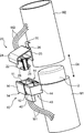
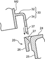
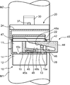
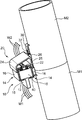
- FIG. 1 is a perspective view showing first and second members according to an embodiment of the present invention and an electrical connection device installed around the first and second members, and a perspective view showing a state before the first and second members are coupled to each other. It is. It is a cross-sectional side view which shows the structure for engagement with the connector holding member and 2nd connector in the said electrical connection apparatus.
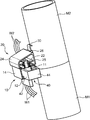
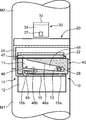
- FIG. 3 is a perspective view showing a state where the first and second members are connected to each other and the first connector and the second connector face each other.
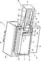
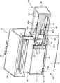
- FIG. 4 is a partial cross-sectional perspective view showing a relative positional relationship between the operation surface of the fitting operation member and the operated portion of the second connector in the state shown in FIG. 3.
- FIG. 3 is a perspective view showing a state where the first and second members are connected to each other and the first connector and the second connector face each other.
- FIG. 4 is a partial cross-sectional perspective view showing a relative positional relationship between the operation surface of the fitting operation member and the operated portion of the second connector in the state shown
- FIG. 5 is a cross-sectional front view showing a state in which the fitting operation member is operated from the state shown in FIG. 4 to a position where an operation surface of the fitting operation member comes into contact with the operated portion.
- FIG. 6 is a perspective view showing a state where the operation of the fitting operation member further proceeds from the state shown in FIG. 5 and the fitting between the first connector and the second connector is completed.
- It is a cross-sectional front view which shows the state shown by FIG. The operation surface of the fitting operation member and the operated portion of the second connector in a state corresponding to the state shown in FIG. 4 and in a state where the operated portion is at a higher position than the position shown in FIG.
- FIG. 9 is a cross-sectional front view showing a state in which the fitting operation member is operated from the state shown in FIG. 8 to a position where the operation surface of the fitting operation member comes into contact with the operated portion.
- the electrical connection device can be rotated relative to the plurality of first wiring members W1 wired to the first member M1 within a predetermined range with respect to the first member M1.
- the first connector 10, the second connector 20, and the connector holding member are for electrical connection between the second wiring members W2 wired to the second member M2 coupled to the first member M2. 30 and a fitting operation member 40.
- the first member M1 has a columnar shape or a cylindrical shape extending in the vertical direction, and an upper end portion thereof constitutes a fitting portion 2 having a cylindrical outer peripheral surface whose diameter is smaller than that of other portions.
- the second member M2 has a cylindrical shape or a columnar shape having a lower end into which the insertion portion 2 can be inserted.
- first member M1 is disposed on the lower side and the second member M2 is disposed on the upper side, but the arrangement of the first and second members according to the present invention is not limited. Further, the shapes of the first and second members are not limited.
- the first connector 10 is connected to the terminals of the plurality of first wiring members W1.
- the plurality of first wiring members W1 are routed along the outer peripheral surface of the first member M1.
- the first connector 10 includes a plurality of connector terminals (male connector terminals in this embodiment) and a connector housing 12 which are not shown.
- the plurality of connector terminals are connected to respective terminals of the plurality of first wiring members W1.
- the connector housing 12 holds the rear portion of each connector terminal leaving the tip portion (male electrical contact portion).
- the connector housing 12 includes a hood 11 that surrounds the distal end portion of each connector terminal, and the hood 11 faces upward (that is, faces the second member M2). In this embodiment, it is fixed on the outer peripheral surface in the vicinity of the fitting portion 2.
- the fixing of the first connector 10 to the first member M1 may be performed in a state where both are in direct contact, or by the connection of the first connector 10 to the first member M1 via a bracket or the like. It may be done.
- the first connector 10 functions as a holding connector that holds the fitting operation member 40.
- the first connector 10 includes a pair of fitting operation member holding portions 14 formed integrally with the connector housing 12 in addition to the connector housing 12.
- the fitting operation member 40 and the fitting operation member holding part 14 will be described in detail later.
- the second connector 20 is connected to the terminals of the plurality of second wiring members W2.
- the plurality of second wiring members W2 are routed along, for example, the outer peripheral surface of the second member M1, similarly to the first wiring member W1.
- the second connector 20 has a plurality of connector terminals (in this embodiment, female connector terminals), a connector housing 22, a cover 24, and a held portion 26, which are not shown.
- the plurality of connector terminals are connected to respective terminals of the plurality of second wiring members W2.
- the connector housing 22 holds the connector terminals so that the female electrical contact portion at the tip of each connector terminal is opened to the outside.
- the connector housing 22 has an outer shape that can be fitted inside the hood 11 of the connector housing 12, and with the fitting, the connector terminal held by the connector housing 12 and the connector housing 22 The held connector terminals are fitted to each other to form an electrical connection between the first wiring member W1 and the second wiring member W2. That is, the first connector 10 and the second connector are fitted to each other along the fitting direction parallel to the direction in which the connector housing 22 is inserted into the hood 11, thereby the first wiring member W1 and the first connector. 2. Electrical connection with the wiring material W2 is enabled.
- the fitting direction is a vertical direction, that is, a direction parallel to the rotation center axis.
- the connector housing 22 has an attachment position, specifically a first position where the connector housing 12 can be opposed to the connector housing 12 in the fitting direction when the first member M1 and the second member M2 are connected.
- the second member M2 is attached to the second member M2 via the connector holding member 30 at a position on the outer peripheral surface of the lower end portion of the two members M2.
- the first connector and the second connector face each other in the fitting direction means that, as described above, the first connector and the second connector are separated from each other in the fitting direction. Both the opposing state and the provisional fitting state in which a part of the first connector and the second connector overlap in the fitting direction are included.
- “opposing each other” means that the upper end of the hood 11 of the first connector 10 and the lower end of the connector housing 22 of the second connector 20 overlap as shown in FIGS. 3 and 4. This means a state in which the connector housing 22 is shallowly fitted in the hood 11.
- the cover 24 has a shape that covers the connector housing 22 from above.
- the cover 24 has a back surface 25 that faces the outer peripheral surface of the second member M ⁇ b> 2, and the held portion 26 is formed on the back surface 25.
- the held portion 26 is a portion that is held by the connector holding member 30.
- the connector holding member 30 holds the held portion 26 of the second connector 20 so that the second connector 20 is positioned at the attachment position by being fixed to the second member M2, and the second connector 20 has a function of allowing the held portion 26 to be detached from the connector holding member 30 in the fitting direction by applying an external force in the fitting direction, that is, a downward external force.
- the connector holding member 30 has a tongue-like shape protruding downward from the outer peripheral surface of the second member M2.
- the connector holding member 30 includes a base portion 32 that protrudes radially outward from the outer peripheral surface of the second member M2, and a holding portion that extends downward from the outer end of the base portion 32. 34, and a retaining hole 37 is formed in the lower end portion of the holding portion 34 so as to penetrate the holding portion 34 in the radial direction.
- the connector holding member according to the present invention is formed as a member independent of the second member, and may be joined to the second member by welding or other means. It may be formed integrally, that is, so as to constitute a single member together with the second member.
- the held portion 26 has a box shape that defines an insertion space together with the back surface 25 of the cover 24.
- the insertion space is a space opened up and down and has a shape that allows the holding portion 34 to be inserted into the insertion space through the upper end thereof.
- the held portion 26 has a locked protrusion 27 that partially protrudes into the insertion space, and the locking hole of the holding portion 34 into which the locked protrusion 27 is inserted into the insertion space.
- the held portion 26 is held by the holding portion 34 by being fitted into 37. Furthermore, when a certain amount or more of downward external force is applied to the second connector 20 including the held portion 26 from this state, the locked protrusion 27 is moved downward from the locking hole 37.
- the held part 26 can be detached from the holding part 34 by being detached.
- the fitting operation member 40 has an operation direction (this direction intersecting with the fitting direction (vertical direction in this embodiment)) by the fitting operation member holding portion 14 of the first connector 10 which is the holding connector.
- the direction can be relatively moved in a direction orthogonal to the fitting direction and in a horizontal direction orthogonal to the radial direction of the first and second members M1 and M2.
- the fitting operation member 40 has a connector operation portion, and the connector operation portion is in a state where the first and second connectors 10 and 20 face each other in the fitting direction as described above (in this embodiment, In the temporary fitting state shown in FIGS.
- the fitting operation member 40 is operated so as to move relative to the first connector 10 in the operation direction, so that it is opposite to the holding connector.
- Side operated connector (second connector 20 in this embodiment) is drawn toward the first connector 10 side (lower side in this embodiment) along the fitting direction, and the first connector and the second connector. And the second connector 20 is detached from the connector holding member 30 in the detaching direction.
- the fitting operation member 40 has a pair of side walls 42 and an end wall 44 integrally.
- the pair of side walls 42 are arranged in an operation width direction (a depth direction in FIG. 4) that is a horizontal direction orthogonal to the operation direction in an upright posture parallel to each other, and the end walls 44 are arranged in the pair of the operation directions.
- One end of the side wall 42 (the rear end in the operation direction; the right end in FIG. 4) is connected to the operation width direction.
- the fitting operation member 40 is mounted on the connector housing 12 so as to sandwich the hood 11 of the first connector 10 from both sides in the arrangement direction. In this mounted state, the operation direction ( It is possible to make a relative movement in the left-right direction in FIG.
- each fitting operation member holding portion 14 has a shape for holding the side walls 42 so as to be held at the outer positions.
- each fitting operation member holding portion 14 integrally includes a bottom wall 15 and an outer wall 16.
- the bottom wall 15 supports the side wall 42 at a position below the corresponding side wall 42.
- the outer wall 16 extends upward from the outer end of the bottom wall 15 so as to sandwich the side wall 42 between the outer wall 16 and the outer surface of the hood 11. That is, the fitting operation member holding part 14 allows the side walls 42 of the fitting operation member 40 to slide in the operation direction along the outer surface of the hood 11.
- the side wall 42 is held at a position outside thereof.
- the fitting operation member holding portion 14 moves the fitting operation member 40 into an operation start position as shown in FIGS. 3 and 4 and an operation end position as shown in FIGS. It has a function of being detachably locked at a downstream position (left position in FIG. 4).
- the fitting operation member 40 has a function capable of being detachably locked at each of the operation start position and the operation end position.
- a flexure piece 45 that can be deflected upward is formed at the lower end of the front side portion (left side portion in FIG. 4) of the operation direction in the side wall 42, and a free end portion of the flexure piece 45 is formed.
- a locked protrusion 45a protruding downward is formed.
- the fitting operation member 40 is in the operation start position and the operation end position on the bottom wall 15 of the fitting operation member holding portion 14, the engagement protrusion 45a is fitted.
- a first locking hole 15a and a second locking hole 15b are formed.
- the second connector 20 which is the operated connector has a pair of operated portions 28.
- Each operated portion 28 protrudes outward in the operation width direction from a pair of side surfaces facing the operation width direction (horizontal direction orthogonal to the operation direction; depth direction in FIG. 4) of the side surfaces of the connector housing 22. To do.
- the position of each operated portion 28 is a position close to the lower end of each connector housing 22 and a position close to the end wall 44 of the fitting operation member 40 held by the fitting operation member holding portion 14 (FIG. 4). Is set to the right).
- each insertion groove 13 has a shape that accepts the insertion of the operated portion 28 from above when the connector housing 22 of the second connector 20 is inserted into the inside of the hood 11, specifically, downward from the upper end of the hood 11.
- a shape extending to The insertion of the operated portion 28 into the insertion groove 13 allows the connector housing 22 to be inserted into the hood 11 while avoiding interference between the operated portion 28 and the hood 11.
- the protruding dimension of each operated portion 28 is such that the end of the operated portion 28 protrudes further outward from the outer surface of the hood 11 in a state where the operated portion 28 is inserted in the insertion groove 13. It is set to be.
- the connector operating portion of the fitting operation member 40 comes into contact with the operated portion 28 as the fitting operation member 40 moves in the operating direction, forcing the operated portion 28 in the fitting direction. This is the part to be displaced (pressed down in this embodiment).
- each side wall 42 of the fitting operation member 40 is recessed outward from the other inner side surface and protrudes further outward than the hood 11.
- An operation groove 46 for receiving the end portion) is formed, and an operation surface constituting the connector operation portion is formed by a recess of the operation groove 46.
- the operation groove 46 has an insertion port 47 and a main body groove 48.
- the insertion port 47 is formed at a position for receiving insertion of the operated portion 28 from above in a state where the fitting operation member 40 is at the operation start position. Specifically, the insertion port 47 is formed at a position near the front end (the left end in FIG. 4) in the operation direction of each side wall 42 and at the upper end position of the side wall 42, and opens upward. Yes.
- the body groove 48 extends from a start end (end on the front side in the operation direction; left end in FIG. 4) located in the lower side of the insertion port 47 in a direction opposite to the operation direction (right direction in FIG. 4) and a terminal end (operation direction). It has a shape in which the width in the vertical direction becomes narrower toward the rear end (right end in FIG. 4).
- the vertical width of the starting end of the main body groove 48 is set to a dimension sufficiently larger than the diameter of the operated portion 48.
- the upper and lower ends of the main body groove 48 are defined by an upper end surface 48a and a lower end surface 48b, respectively.
- the upper and lower end surfaces 48a, 48b are both inclined (to the operation direction) so as to become lower toward the rear end (right end in FIG. 4) of the side wall 42 in the operation direction.
- the inclination angle of the upper end surface 48a is larger than that of the lower end surface 48b, and the vertical width of the main body groove 48 becomes narrower toward the rear end in the operation direction by the difference of the inclination angle.
- the operation surface of the fitting operation member 40 is constituted by the upper end surface 48 a of the main body groove 48. That is, the upper end surface 48a abuts against the operated portion 28 in the process in which the fitting operation member 40 is operated in the operation direction from the operation start position (FIG. 5), and further fitting is performed from that position.
- the operated portion 28 and the entire second connector 20 including the operated portion 28 are pushed down.
- the position and inclination angle of the upper end surface 48a are set so that the upper end surface 48a functions in this way.
- first and second connectors 10 and 20 are installed on the first member M1 and the second member M2, respectively.
- the plurality of first wiring members W1 are wired around the first member M1 in a state where the first connector 10 is connected to the terminals of the plurality of first wiring members W1. Further, the first connector 10 is fixed at a regular fixed position as shown in FIG. 1 or the like, that is, at a position on the outer peripheral surface of the first member M1 in the vicinity of the upper end of the first member M1.
- the plurality of second wiring members W2 are wired around the second member M2 in a state where the second connector 20 is connected to the terminals of the plurality of second wiring members W2. Further, the connector holding member 30 is placed at a normal mounting position as shown in FIG. 1 or the like, that is, at a position on the outer peripheral surface of the second member M2 in the vicinity of the lower end of the second member M2. Mounted through.
- the holding portion 34 is 2
- the second connector 20 is set so as to be inserted into the insertion space inside the held portion 26 of the connector 20, and the locked projection 27 of the held portion 26 is inserted into the locking hole 37 of the holding portion 34.
- the held portion 26 is held by the holding portion 34 by fitting.
- the fitting operation member 40 is held at the operation start position shown in FIGS. 1, 3 and 4 with respect to the first connector 10 which is a holding connector. Specifically, the fitting operation member 40 has the engagement protrusion 45 a fitted into the first locking hole 15 a of the bottom wall 15 of the fitting operation member holding portion 14. The insertion port 47 is locked at a position that matches the insertion groove 13 of the hood 11.
- the relative angle of the second member M2 with respect to the first member M1 (the angle in the direction of rotation) is such that the second connector 20 faces the first connector 10 in the fitting direction. It is set as follows. In this embodiment, as shown in FIGS. 3 and 4, the hood 11 of the connector housing 12 of the first connector 10 is coupled with the connection in the direction along the central axis of the first and second members M1 and M2. So that the lower portion of the connector housing 22 of the second connector 20 is shallowly inserted therein, that is, the first and second connectors 10 and 20 are temporarily fitted in a fitting direction parallel to the connecting direction. In addition, the relative angle of the second member M2 with respect to the first member M1 is determined.
- the operated portion 28 of the second connector 20 protrudes from the side surface of the connector housing 22 in the operation width direction.
- the insertion groove 13 formed in the insertion portion 47 enters the start end side portion (the left side portion in FIG. 4) of the operation groove 46 through the insertion port 47 of the fitting operation member 40, thereby Interference with the hood 11 and the fitting operation member 40 can be avoided.
- the insertion groove 13 and the insertion port 47 allow the connector housing 20 to be temporarily fitted to the hood 11 regardless of the protrusion of the operated portion 28 from the connector housing 20.
- the fitting operation member 40 is further provided. Is operated in the operation direction (the direction indicated by the arrow Dp in FIG. 4) from the operation start position to the operation completion position shown in FIG. 7, that is, relative to the first connector 10 in the operation direction.
- the main fitting of the first connector 10 and the second connector 20 (specifically, the normal fitting of the connector terminal not shown in the first connector 10 and the connector terminal not shown in the second connector 20)
- the second connector 20 is detached from the connector holding member 30 at the same time.
- the upper end surface 48a of the operation groove 46 of the fitting operation member 40 As shown in FIG. 5, between the fitting operation member 40 and the fitting completion position.
- the operation surface that inclines so as to become lower as it advances in the operation direction abuts against the operated portion 28 obliquely from above, and the fitting operation member 40 is further operated from this state to the fitting completion position.
- the upper end surface 48a (operation surface) pushes down the operated portion 28 and thus the entire second connector 20 including this. Due to the pushing-down force, the engagement between the latching protrusion 27 of the held portion 26 included in the second connector 20 and the locking hole 37 of the connector holding member 30 is released, and the second connector 20 is detached from the connector holding member 30. While the connector 20 is detached downward, the vertical fitting (fitting direction) of the second connector 20 and the first connector 10 is realized.
- the first and second connectors 10 and 10 can be simply operated by simply moving the fitting operation member 40 from the operation start position to the operation completion position in the operation direction. Both the fitting of the two members 20 and the detachment of the second connector 20 from the connector holding member 30 are achieved.
- the second connector 20 is detached from the connector holding member 30 even though the first and second connectors 10 and 20 are engaged with each other, the second member M2 is predetermined with respect to the first member M1. Within the range (in this embodiment, within the range allowed by the extra length of the second wiring member W2).
- the apparatus according to the present embodiment pushes down the operated portion 28 by abutting the operated portion (the upper end surface 48a of the operating groove 46) inclined with respect to the operating direction and the operated portion 28 (in other words, Therefore, when the connection between the first and second members M1 and M2 is completed, there is some variation in the position of the operated portion 28 in the connecting direction.
- the fitting between the first and second connectors 10 and 20 and the detachment of the second connector 20 from the connector holding member 30 can be achieved.
- the operated portion 28 is located at the position shown in FIG. 8, that is, shown in FIG. 4, at the stage of completion of the connection of the first and second members M1, M2. Even when the position remains above the position to be operated, the fitting operation member 40 is operated in the operation direction from this state, and the timing corresponding to the position of the operated portion 28 (shown in FIG. 4).
- the operation surface comes into contact with the operated portion 28 at a timing earlier than the case where the operated portion 28 can be moved in the fitting direction by further operation from that position. .
- the variation in the position of the operated portion 28 in the fitting direction can be absorbed by the shift in timing at which the upper end surface 48 a contacts the operated portion 28.
- the present invention is not limited to the embodiment described above.
- the present invention includes, for example, the following embodiments.
- the fitting direction of a 1st connector and a 2nd connector is not limited to the direction parallel to the rotation central axis of a 1st and 2nd member.
- the fitting direction is a direction along the direction of relative rotation of the first and second members (for example, in the embodiment, the tangential direction of the outer peripheral surfaces of the first and second members M1 and M2 or close thereto) Direction).
- the fitting direction of the first and second connectors is a direction parallel to the rotation center axis when connecting the first member and the second member.
- the operation direction of a fitting operation member should just be a direction which cross
- the smaller the component in the fitting direction included in the operation direction the greater the function as a booster mechanism that reduces the operating force required for fitting.
- the first connector 10 is a holding connector that holds the fitting operation member 40
- the second connector 20 is operated by the fitting operation member 40
- the second connector may be a holding connector that holds the fitting operation member
- the first connector may be an operated connector that is operated by the fitting operation member.
- the actual movement of the fitting operation member is not only the relative movement in the operation direction with respect to the second connector, but also the movement in the fitting direction toward the first connector (in other words, the connector
- the operation of the fitting operation member becomes complicated by the combined movement including the movement in which the second connector is detached from the holding member in the separation direction.
- the first connector fixed to the first member is a holding connector
- the actual movement of the fitting operation member is a simple movement including only the operation direction. There is an advantage that the operation of the member becomes easier.
- an electrical connection device capable of efficiently performing electrical connection between members coupled to each other so that relative rotation is possible.
- a first wiring member wired to the first member, and the rotation center axis so that the first member can be rotated relative to the first member about a predetermined rotation center axis.
- An electrical connection device for electrical connection with a second wiring member wired in a second member coupled in a coupling direction along the first member, and connected to the first wiring member;
- a first connector to be fixed, connected to the second wiring member, attached to the second member, and formed into the electrical connection by fitting with the first connector in a specific fitting direction.
- a connector holding member connected to the second connector and the second member, wherein the first connector and the second connector are connected in the fitting direction in a state where the first member and the second member are connected.
- the second connector at a position where it can face each other.
- a connector holding member, and a fitting operation member held by the holding connector selected from the first connector and the second connector so as to be relatively movable in an operation direction intersecting the fitting direction. Prepare.
- the fitting operation member is connected to the holding connector in a state in which the first member and the second member are connected and the first connector and the second connector face each other in the fitting direction.
- the operated connector on the opposite side of the holding connector of the first connector and the second connector is pulled toward the holding connector side along the fitting direction by moving relative to the holding connector.
- a connector operating portion that allows the second connector to be detached from the connector holding member in the fitting direction.
- the first member and the second member are coupled to each other in the coupling direction, and the first connector and the second connector are opposed to each other in the fitting direction.
- the first connector and the second connector can be simply operated by simply moving the fitting operation member held by the holding connector, which is one of the connectors, relative to the holding connector in the operation direction crossing the fitting direction.
- the fitting of each other and the removal of the second connector from the connector holding member can be performed simultaneously. That is, only by a simple operation of the fitting operation member, the electrical connection by fitting the first and second connectors and the relative relationship between the first member and the second member by detaching the second connector from the connector holding member. Both permissible rotations can be realized at the same time.
- the fitting direction is a direction parallel to the rotation center axis. This facilitates the work of aligning the first connector and the second connector when the first member and the second member are connected, that is, the work of making the two connectors face each other in the fitting direction.
- the operated connector has an operated portion that receives an operation by the connector operating portion, and the connector operating portion is moved along with the relative movement of the fitting operation member in the operation direction with respect to the holding connector. It is preferable to include an operation surface that is in contact with the operated portion and is inclined with respect to the operating direction so as to draw the operated portion toward the holding connector.
- the operation surface can absorb the variation in the position of the operated portion and can realize the fitting between the first and second connectors and the detachment of the second connector from the connector holding member.
- the holding connector may be either the first connector or the second connector, but the first connector fixed to the first member is the holding connector, that is, the fitting operation in the operation direction.
- a connector that holds the fitting operation member so as to allow relative movement of the member is preferable. This means that compared to the case where the second connector that must be detached from the connector holding member is a holding connector, the actual movement of the fitting operation member is a simple movement whose direction matches the operation direction. Thereby, the operation of the fitting operation member can be made easier.
Abstract
The present invention provides an electrical connection apparatus that can efficiently establish an electrical connection spanning between members rotating relative to each other. This electrical connection apparatus is provided with: a first connector (10) connected to a first wiring member (W1) for wiring to a first member (M1), the first connector (10) being fixed to the first member (M1); a second connector (20) connected to a second wiring member (W2) for wiring to a second member (M2), the second connector (20) being attached to the second member (M2); a connector holding member (30) linked to the second member (M2) and detachably holding the second connector (20); and a fitting operation member (40) held by the first connector (10) or the second connector (20). The fitting operation member (40) is operated in the operation direction, which intersects the fitting direction, with the first and second connectors (10, 20) facing each other, whereby the first and second connectors (10, 20) are fitted in the fitting direction and the second connector (20) is detached from the connector holding member (30).
Description
本発明は、相対的に回動可能となるように互いに連結された部材同士の間に跨る電気接続を行うための電気接続装置に関する。
The present invention relates to an electrical connection device for performing electrical connection between members coupled to each other so as to be relatively rotatable.
従来、回路同士の電気的接続を行うための装置として、互いに嵌合可能なコネクタを備えたものが広く用いられている。各コネクタは、所定の回路に電線などを介して接続されるコネクタ端子と、当該コネクタ端子を保持するコネクタハウジングと、を含み、前記各コネクタのコネクタ端子同士の嵌合により、それぞれのコネクタに接続された回路同士の電気的接続が行われる。
Conventionally, devices equipped with connectors that can be fitted to each other are widely used as devices for electrical connection between circuits. Each connector includes a connector terminal connected to a predetermined circuit via an electric wire and the like, and a connector housing that holds the connector terminal, and is connected to each connector by fitting the connector terminals of the connectors. The connected circuits are electrically connected.
前記各コネクタは、適当な取付部材を介して車両等の適当な部位に取付けられ、使用される。例えば特許文献1には、電気接続装置を構成するコネクタが固定用ブラケットを介して車体に取付けられるものが開示されている。
The connectors are used by being attached to appropriate parts such as vehicles via appropriate attachment members. For example, Patent Document 1 discloses a connector in which an electrical connection device is attached to a vehicle body via a fixing bracket.
前記のようなコネクタが取付けられる部材の中には、例えば車体とドア、車体とドアミラー、ステアリングシャフトとこれを回動可能に支持する部材のように、所定範囲内で相対的な回動が可能となるように互いに連結される部材がある。このような相対回動が予定された一対の部材のそれぞれに配線材が配索され、かつ、それぞれの配線材にコネクタが接続されて当該コネクタ同士が嵌合される場合、その嵌合にかかわらず前記相対回動を可能にするためには、一方のコネクタを当該コネクタが取付けられる部材から切り離して他方のコネクタに嵌合しなければならない。このようなコネクタの切り離し作業及びコネクタ同士の嵌合作業は、いずれも煩雑であってかつ手作業で行われなければならない。このことは、作業効率の向上の妨げとなる。
Among the members to which the above connectors are attached, for example, a vehicle body and a door, a vehicle body and a door mirror, a steering shaft and a member that rotatably supports this can be rotated within a predetermined range. There are members that are connected to each other. When a wiring member is routed to each of the pair of members scheduled for such relative rotation and a connector is connected to each wiring member and the connectors are fitted to each other, the fitting is involved. In order to enable the relative rotation, one connector must be separated from a member to which the connector is attached and fitted to the other connector. Both the connector disconnecting operation and the connector fitting operation are complicated and must be performed manually. This hinders improvement in work efficiency.
本発明は、相対的な回動が可能となるように互いに連結される部材同士の間に跨る電気接続を効率よく行うことが可能な電気接続装置を提供することを目的とする。
It is an object of the present invention to provide an electrical connection device capable of efficiently performing electrical connection between members coupled to each other so that relative rotation is possible.
提供されるのは、第1部材に配線される第1配線材と、この第1部材に対して所定の回動中心軸回りに相対的な回動が可能となるように当該回動中心軸に沿う連結方向に連結される第2部材に配線される第2配線材と、の電気接続を行うための電気接続装置であって、前記第1配線材に接続され、かつ前記第1部材に固定される第1コネクタと、前記第2配線材に接続され、かつ、前記第2部材に取付けられるとともに、前記第1コネクタと特定の嵌合方向に嵌合することにより前記電気接続を形成する第2コネクタと、前記第2部材につながるコネクタ保持部材であって、前記第1部材と前記第2部材とが連結された状態で前記第1コネクタと前記第2コネクタとが前記嵌合方向に互いに対向することが可能となる位置に前記第2コネクタを保持するとともに、当該第2コネクタに前記嵌合方向の外力が加えられることにより当該嵌合方向に当該第2コネクタが当該コネクタ保持部材から離脱することを許容するように当該第2コネクタを保持するコネクタ保持部材と、前記第1コネクタ及び前記第2コネクタの中から選ばれる保持コネクタに前記嵌合方向と交差する操作方向に相対移動可能となるように保持される嵌合操作部材と、を備える。前記嵌合操作部材は、前記第1部材と前記第2部材とが連結されて前記第1コネクタ及び前記第2コネクタが前記嵌合方向に互いに対向した状態で前記保持コネクタに対して前記操作方向に相対移動することにより前記第1コネクタ及び前記第2コネクタのうち前記保持コネクタと反対側の被操作コネクタを前記嵌合方向に沿って前記保持コネクタ側に引き寄せて前記第1コネクタ及び第2コネクタを互いに嵌合させるとともに前記第2コネクタを前記コネクタ保持部材から前記嵌合方向に離脱させるコネクタ操作部を有する。
What is provided is a first wiring member wired to the first member, and the rotation center axis so that the first member can be rotated relative to the first member about a predetermined rotation center axis. An electrical connection device for electrical connection with a second wiring member wired in a second member coupled in a coupling direction along the first member, and connected to the first wiring member; A first connector to be fixed, connected to the second wiring member, attached to the second member, and formed into the electrical connection by fitting with the first connector in a specific fitting direction. A connector holding member connected to the second connector and the second member, wherein the first connector and the second connector are connected in the fitting direction in a state where the first member and the second member are connected. The second connector at a position where it can face each other. And holding the second connector so as to allow the second connector to be detached from the connector holding member in the fitting direction when an external force in the fitting direction is applied to the second connector. A connector holding member, and a fitting operation member held by the holding connector selected from the first connector and the second connector so as to be relatively movable in an operation direction intersecting the fitting direction. Prepare. The fitting operation member is connected to the holding connector in a state in which the first member and the second member are connected and the first connector and the second connector face each other in the fitting direction. The operated connector on the opposite side of the holding connector of the first connector and the second connector is pulled toward the holding connector side along the fitting direction by moving relative to the holding connector. And a connector operating portion that allows the second connector to be detached from the connector holding member in the fitting direction.
ここで「前記第1コネクタと前記第2コネクタとが前記嵌合方向に互いに対向する」とは、当該第1コネクタ及び当該第2コネクタ同士が当該嵌合方向に互いに離間して対向する状態と、当該第1コネクタ及び当該第2コネクタの一部同士が当該嵌合方向に重なった仮嵌合状態と、の双方を含む意である。
Here, “the first connector and the second connector face each other in the fitting direction” means that the first connector and the second connector are spaced apart from each other in the fitting direction. It is meant that both the first connector and the second connector partially include a temporary fitting state in which the first connector and the second connector overlap each other in the fitting direction.
本発明の好ましい実施の形態を、図面を参照しながら説明する。
A preferred embodiment of the present invention will be described with reference to the drawings.
この実施の形態に係る電気接続装置は、第1部材M1に配線される複数の第1配線材W1と、前記第1部材M1に対して所定範囲内で相対的な回動が可能となるように連結される第2部材M2に配線される複数の第2配線材W2と、の間での電気接続を行うためのものであり、第1コネクタ10と、第2コネクタ20と、コネクタ保持部材30と、嵌合操作部材40と、を備える。
The electrical connection device according to this embodiment can be rotated relative to the plurality of first wiring members W1 wired to the first member M1 within a predetermined range with respect to the first member M1. The first connector 10, the second connector 20, and the connector holding member are for electrical connection between the second wiring members W2 wired to the second member M2 coupled to the first member M2. 30 and a fitting operation member 40.
この実施の形態において、前記第1部材M1は、上下方向に延びる円柱状または円筒状をなし、その上端部は他の部分に比べて直径が小さい円筒状外周面をもつ嵌入部2を構成する。前記第2部材M2は、前記嵌入部2が嵌入可能な下端をもつ円筒状または円柱状をなす。当該第2部材M2への当該嵌入部2の嵌入により、前記第1部材M1及び前記第2部材M2はその中心軸に相当する回動中心軸回りに相対的な回動が可能となるように、前記回動中心軸に沿う連結方向(図1に矢印Dcで示される方向)に連結される。
In this embodiment, the first member M1 has a columnar shape or a cylindrical shape extending in the vertical direction, and an upper end portion thereof constitutes a fitting portion 2 having a cylindrical outer peripheral surface whose diameter is smaller than that of other portions. . The second member M2 has a cylindrical shape or a columnar shape having a lower end into which the insertion portion 2 can be inserted. By fitting the fitting portion 2 into the second member M2, the first member M1 and the second member M2 are capable of relative rotation around a rotation center axis corresponding to the center axis. , And connected in the connecting direction (direction indicated by arrow Dc in FIG. 1) along the rotation center axis.
この実施の形態において、前記第1部材M1は下側に、前記第2部材M2は上側に、それぞれ配置されるが、本発明に係る第1及び第2部材の配置は限定されない。また、当該第1及び第2部材の形状も限定されない。
In this embodiment, the first member M1 is disposed on the lower side and the second member M2 is disposed on the upper side, but the arrangement of the first and second members according to the present invention is not limited. Further, the shapes of the first and second members are not limited.
前記第1コネクタ10は、前記複数の第1配線材W1の端末に接続される。当該複数の第1配線材W1は、例えば前記第1部材M1の外周面に沿うように配索される。
The first connector 10 is connected to the terminals of the plurality of first wiring members W1. For example, the plurality of first wiring members W1 are routed along the outer peripheral surface of the first member M1.
前記第1コネクタ10は、図略の複数のコネクタ端子(この実施の形態では雄型のコネクタ端子)と、コネクタハウジング12と、を有する。前記複数のコネクタ端子は、前記複数の第1配線材W1のそれぞれの端末に接続される。前記コネクタハウジング12は、前記各コネクタ端子の先端部分(雄型電気接触部)を残してその後ろ側の部分を保持する。前記コネクタハウジング12は、前記各コネクタ端子の先端部分を囲むフード11を有し、このフード11が上を向く(つまり第2部材M2の側を向く)姿勢で前記第1部材M1の所定部位、この実施の形態では前記嵌入部2の近傍の外周面上、に固定される。当該第1部材M1への第1コネクタ10の固定は、両者が直接接触する状態で行われてもよいし、ブラケット等を介しての前記第1部材M1への前記第1コネクタ10の連結により行われてもよい。
The first connector 10 includes a plurality of connector terminals (male connector terminals in this embodiment) and a connector housing 12 which are not shown. The plurality of connector terminals are connected to respective terminals of the plurality of first wiring members W1. The connector housing 12 holds the rear portion of each connector terminal leaving the tip portion (male electrical contact portion). The connector housing 12 includes a hood 11 that surrounds the distal end portion of each connector terminal, and the hood 11 faces upward (that is, faces the second member M2). In this embodiment, it is fixed on the outer peripheral surface in the vicinity of the fitting portion 2. The fixing of the first connector 10 to the first member M1 may be performed in a state where both are in direct contact, or by the connection of the first connector 10 to the first member M1 via a bracket or the like. It may be done.
この実施の形態に係る第1コネクタ10は、前記嵌合操作部材40を保持する保持コネクタとして機能する。具体的に、当該第1コネクタ10は、前記コネクタハウジング12に加え、これと一体に成形される一対の嵌合操作部材保持部14を有する。前記嵌合操作部材40及び前記嵌合操作部材保持部14については後に詳述する。
The first connector 10 according to this embodiment functions as a holding connector that holds the fitting operation member 40. Specifically, the first connector 10 includes a pair of fitting operation member holding portions 14 formed integrally with the connector housing 12 in addition to the connector housing 12. The fitting operation member 40 and the fitting operation member holding part 14 will be described in detail later.
前記第2コネクタ20は、前記複数の第2配線材W2の端末に接続される。当該複数の第2配線材W2は、前記第1配線材W1と同様、例えば前記第2部材M1の外周面に沿うように配索される。
The second connector 20 is connected to the terminals of the plurality of second wiring members W2. The plurality of second wiring members W2 are routed along, for example, the outer peripheral surface of the second member M1, similarly to the first wiring member W1.
前記第2コネクタ20は、図略の複数のコネクタ端子(この実施の形態では雌型のコネクタ端子)と、コネクタハウジング22と、カバー24と、被保持部26と、を有する。
The second connector 20 has a plurality of connector terminals (in this embodiment, female connector terminals), a connector housing 22, a cover 24, and a held portion 26, which are not shown.
前記複数のコネクタ端子は、前記複数の第2配線材W2のそれぞれの端末に接続される。前記コネクタハウジング22は、前記各コネクタ端子の先端の雌型電気接触部を外部に開放するようにして当該コネクタ端子を保持する。前記コネクタハウジング22は、前記コネクタハウジング12のフード11の内側に嵌入されることが可能な外形を有し、その嵌入に伴って、前記コネクタハウジング12に保持されるコネクタ端子と前記コネクタハウジング22に保持されるコネクタ端子とが互いに嵌合して前記第1配線材W1と前記第2配線材W2との電気接続を形成する。つまり、第1コネクタ10及び第2コネクタは、前記フード11内に前記コネクタハウジング22が嵌入される方向と平行な嵌合方向に沿って互いに嵌合することにより前記第1配線材W1と前記第2配線材W2との電気的接続を可能にする。この実施の形態において、前記嵌合方向は上下方向すなわち前記回動中心軸と平行な方向である。
The plurality of connector terminals are connected to respective terminals of the plurality of second wiring members W2. The connector housing 22 holds the connector terminals so that the female electrical contact portion at the tip of each connector terminal is opened to the outside. The connector housing 22 has an outer shape that can be fitted inside the hood 11 of the connector housing 12, and with the fitting, the connector terminal held by the connector housing 12 and the connector housing 22 The held connector terminals are fitted to each other to form an electrical connection between the first wiring member W1 and the second wiring member W2. That is, the first connector 10 and the second connector are fitted to each other along the fitting direction parallel to the direction in which the connector housing 22 is inserted into the hood 11, thereby the first wiring member W1 and the first connector. 2. Electrical connection with the wiring material W2 is enabled. In this embodiment, the fitting direction is a vertical direction, that is, a direction parallel to the rotation center axis.
前記コネクタハウジング22は、前記第1部材M1と前記第2部材M2とが連結される際に前記コネクタハウジング12と前記嵌合方向に互いに対向することが可能となる取付位置、具体的には第2部材M2の下端部の外周面上の位置、で前記第2部材M2に前記コネクタ保持部材30を介して取付けられる。
The connector housing 22 has an attachment position, specifically a first position where the connector housing 12 can be opposed to the connector housing 12 in the fitting direction when the first member M1 and the second member M2 are connected. The second member M2 is attached to the second member M2 via the connector holding member 30 at a position on the outer peripheral surface of the lower end portion of the two members M2.
本発明にいう「第1コネクタと第2コネクタとが嵌合方向に互いに対向する」とは、上述のように、当該第1コネクタ及び当該第2コネクタ同士が当該嵌合方向に互いに離間して対向する状態と、当該第1コネクタ及び当該第2コネクタの一部同士が当該嵌合方向に重なった仮嵌合状態と、の双方を含む。この実施の形態において「互いに対向する」とは、図3及び図4に示されるように前記第1コネクタ10のフード11の上端と前記第2コネクタ20のコネクタハウジング22の下端とがオーバーラップした状態、つまり当該フード11内に当該コネクタハウジング22が浅く嵌合した仮嵌合状態を意味する。
In the present invention, “the first connector and the second connector face each other in the fitting direction” means that, as described above, the first connector and the second connector are separated from each other in the fitting direction. Both the opposing state and the provisional fitting state in which a part of the first connector and the second connector overlap in the fitting direction are included. In this embodiment, “opposing each other” means that the upper end of the hood 11 of the first connector 10 and the lower end of the connector housing 22 of the second connector 20 overlap as shown in FIGS. 3 and 4. This means a state in which the connector housing 22 is shallowly fitted in the hood 11.
前記カバー24は、前記コネクタハウジング22を上から覆う形状を有する。当該カバー24は、前記第2部材M2の外周面に対して対向する背面25を有し、この背面25上に前記被保持部26が形成されている。当該被保持部26は、前記コネクタ保持部材30により保持される部分である。
The cover 24 has a shape that covers the connector housing 22 from above. The cover 24 has a back surface 25 that faces the outer peripheral surface of the second member M <b> 2, and the held portion 26 is formed on the back surface 25. The held portion 26 is a portion that is held by the connector holding member 30.
前記コネクタ保持部材30は、前記第2部材M2に固定されて前記取付位置に前記第2コネクタ20が位置するように当該第2コネクタ20の前記被保持部26を保持するとともに、当該第2コネクタ20に前記嵌合方向の外力つまり下向きの外力が加えられることにより当該嵌合方向に当該被保持部26が当該コネクタ保持部材30から離脱することを許容する機能を有する。
The connector holding member 30 holds the held portion 26 of the second connector 20 so that the second connector 20 is positioned at the attachment position by being fixed to the second member M2, and the second connector 20 has a function of allowing the held portion 26 to be detached from the connector holding member 30 in the fitting direction by applying an external force in the fitting direction, that is, a downward external force.
この実施の形態に係るコネクタ保持部材30は、前記第2部材M2の外周面から下向きに突出する舌片状をなす。具体的に、当該コネクタ保持部材30は、図2に示すように、前記第2部材M2の外周面から径方向外向きに突出する基部32と、この基部32の外側端から下向きに延びる保持部34と、を有し、保持部34の下端部にこれを前記径方向に貫通する係止用孔37が形成されている。
The connector holding member 30 according to this embodiment has a tongue-like shape protruding downward from the outer peripheral surface of the second member M2. Specifically, as shown in FIG. 2, the connector holding member 30 includes a base portion 32 that protrudes radially outward from the outer peripheral surface of the second member M2, and a holding portion that extends downward from the outer end of the base portion 32. 34, and a retaining hole 37 is formed in the lower end portion of the holding portion 34 so as to penetrate the holding portion 34 in the radial direction.
なお、本発明に係るコネクタ保持部材は、第2部材とは独立した部材として形成されたものであって当該第2部材に溶接その他の手段で接合されるものでもよいし、当該第2部材と一体に、すなわち当該第2部材とともに単一の部材を構成するうように、形成されたものであってもよい。
The connector holding member according to the present invention is formed as a member independent of the second member, and may be joined to the second member by welding or other means. It may be formed integrally, that is, so as to constitute a single member together with the second member.
一方、前記被保持部26は、前記カバー24の背面25とともに挿入空間を画定する箱状をなす。前記挿入空間は、上下に開放された空間であってその上端を通して当該挿入空間内に前記保持部34が挿入されるのを許容する形状を有する。前記被保持部26は、前記挿入空間内に部分的に突出する被係止突起27を有し、この被係止突起27が前記挿入空間内に挿入される前記保持部34の係止用孔37に嵌まり込むことにより、前記被保持部26が前記保持部34に保持される。さらに、この状態から前記被保持部26を含む第2コネクタ20に一定以上の下向きの外力が加えられることにより、前記被係止突起27が前記係止用孔37から離脱方向である下方向に離脱して前記被保持部26が前記保持部34から外れることを可能にする。
On the other hand, the held portion 26 has a box shape that defines an insertion space together with the back surface 25 of the cover 24. The insertion space is a space opened up and down and has a shape that allows the holding portion 34 to be inserted into the insertion space through the upper end thereof. The held portion 26 has a locked protrusion 27 that partially protrudes into the insertion space, and the locking hole of the holding portion 34 into which the locked protrusion 27 is inserted into the insertion space. The held portion 26 is held by the holding portion 34 by being fitted into 37. Furthermore, when a certain amount or more of downward external force is applied to the second connector 20 including the held portion 26 from this state, the locked protrusion 27 is moved downward from the locking hole 37. The held part 26 can be detached from the holding part 34 by being detached.
前記嵌合操作部材40は、前記保持コネクタである前記第1コネクタ10の嵌合操作部材保持部14により、前記嵌合方向(この実施の形態では上下方向)に対して交差する操作方向(この実施の形態では図4に矢印Dpで示されるように前記嵌合方向と直交する方向であって前記第1及び第2部材M1,M2の径方向と直交する水平方向)に相対移動可能となるように保持される。当該嵌合操作部材40は、コネクタ操作部を有し、このコネクタ操作部は、前記のように第1及び第2コネクタ10,20が前記嵌合方向に互いに対向した状態(この実施の形態では図3及び図4に示される前記仮嵌合状態)において前記第1コネクタ10に対して前記嵌合操作部材40が前記操作方向に相対移動するように操作されることにより、前記保持コネクタと反対側の被操作コネクタ(この実施の形態では第2コネクタ20)を前記嵌合方向に沿って前記第1コネクタ10側(この実施の形態では下側)に引き寄せて前記第1コネクタ及び第2コネクタを互いに嵌合させるとともに前記第2コネクタ20を前記コネクタ保持部材30から前記離脱方向に離脱させる機能を有する。
The fitting operation member 40 has an operation direction (this direction intersecting with the fitting direction (vertical direction in this embodiment)) by the fitting operation member holding portion 14 of the first connector 10 which is the holding connector. In the embodiment, as shown by an arrow Dp in FIG. 4, the direction can be relatively moved in a direction orthogonal to the fitting direction and in a horizontal direction orthogonal to the radial direction of the first and second members M1 and M2. To be held. The fitting operation member 40 has a connector operation portion, and the connector operation portion is in a state where the first and second connectors 10 and 20 face each other in the fitting direction as described above (in this embodiment, In the temporary fitting state shown in FIGS. 3 and 4, the fitting operation member 40 is operated so as to move relative to the first connector 10 in the operation direction, so that it is opposite to the holding connector. Side operated connector (second connector 20 in this embodiment) is drawn toward the first connector 10 side (lower side in this embodiment) along the fitting direction, and the first connector and the second connector. And the second connector 20 is detached from the connector holding member 30 in the detaching direction.
この実施の形態に係る嵌合操作部材40は、一対の側壁42と端壁44とを一体に有する。前記一対の側壁42は、互いに平行となる立直姿勢で前記操作方向と直交する水平方向である操作幅方向(図4では奥行方向)に並び、前記端壁44は、前記操作方向について当該一対の側壁42の一方の端部(当該操作方向の後ろ側端部;図4では右側端部)同士を前記操作幅方向につなぐ形状を有する。当該嵌合操作部材40は、前記第1コネクタ10のフード11を前記並び方向の両側から挟むように前記コネクタハウジング12に装着され、この装着状態において、当該コネクタハウジング12に対して前記操作方向(図4では左右方向)に相対移動することが可能である。
The fitting operation member 40 according to this embodiment has a pair of side walls 42 and an end wall 44 integrally. The pair of side walls 42 are arranged in an operation width direction (a depth direction in FIG. 4) that is a horizontal direction orthogonal to the operation direction in an upright posture parallel to each other, and the end walls 44 are arranged in the pair of the operation directions. One end of the side wall 42 (the rear end in the operation direction; the right end in FIG. 4) is connected to the operation width direction. The fitting operation member 40 is mounted on the connector housing 12 so as to sandwich the hood 11 of the first connector 10 from both sides in the arrangement direction. In this mounted state, the operation direction ( It is possible to make a relative movement in the left-right direction in FIG.
前記一対の嵌合操作部材保持部14は、前記各側壁42をさらにその外側の位置で抱き込むように保持する形状を有する。具体的に、各嵌合操作部材保持部14は、底壁15と外側壁16とを一体に有する。前記底壁15は、対応する側壁42の下側の位置で当該側壁42を支持する。前記外側壁16は前記フード11の外側面との間に前記側壁42を挟み込むように前記底壁15の外側端から上向きに延びる。すなわち、当該嵌合操作部材保持部14は、前記嵌合操作部材40の各側壁42が前記フード11の外側面に沿って前記操作方向にスライドすることを許容しながら当該嵌合操作部材40の側壁42をその外側の位置で保持する。
The pair of fitting operation member holding portions 14 have a shape for holding the side walls 42 so as to be held at the outer positions. Specifically, each fitting operation member holding portion 14 integrally includes a bottom wall 15 and an outer wall 16. The bottom wall 15 supports the side wall 42 at a position below the corresponding side wall 42. The outer wall 16 extends upward from the outer end of the bottom wall 15 so as to sandwich the side wall 42 between the outer wall 16 and the outer surface of the hood 11. That is, the fitting operation member holding part 14 allows the side walls 42 of the fitting operation member 40 to slide in the operation direction along the outer surface of the hood 11. The side wall 42 is held at a position outside thereof.
さらに、前記嵌合操作部材保持部14は、前記嵌合操作部材40を図3及び図4に示すような操作開始位置と図6及び図7に示す操作終了位置(操作開始位置よりも操作方向下流側の位置;図4では左側の位置)とでそれぞれ着脱可能に係止する機能を有する。換言すれば、嵌合操作部材40は前記操作開始位置及び前記操作終了位置のそれぞれにおいて着脱可能に係止されることが可能な機能を有する。
Further, the fitting operation member holding portion 14 moves the fitting operation member 40 into an operation start position as shown in FIGS. 3 and 4 and an operation end position as shown in FIGS. It has a function of being detachably locked at a downstream position (left position in FIG. 4). In other words, the fitting operation member 40 has a function capable of being detachably locked at each of the operation start position and the operation end position.
具体的に、前記側壁42のうち前記操作方向の前側部分(図4では左側部分)の下端には、上向きに撓み変位が可能な撓み片45が形成され、この撓み片45の自由端部に下向きに突出する被係止突起45aが形成されている。これに対し、前記嵌合操作部材保持部14の底壁15には、前記嵌合操作部材40が前記操作開始位置及び前記操作終了位置にそれぞれあるときに前記被係止突起45aの嵌まり込みを受け入れる第1係止用孔15a及び第2係止用孔15bが形成されている。
Specifically, a flexure piece 45 that can be deflected upward is formed at the lower end of the front side portion (left side portion in FIG. 4) of the operation direction in the side wall 42, and a free end portion of the flexure piece 45 is formed. A locked protrusion 45a protruding downward is formed. On the other hand, when the fitting operation member 40 is in the operation start position and the operation end position on the bottom wall 15 of the fitting operation member holding portion 14, the engagement protrusion 45a is fitted. A first locking hole 15a and a second locking hole 15b are formed.
前記被操作コネクタである第2コネクタ20は、一対の被操作部28を有する。各被操作部28は、前記コネクタハウジング22の側面のうち前記操作幅方向(前記操作方向と直交する水平方向;図4では奥行方向)を向く一対の側面から当該操作幅方向の外向きに突出する。各被操作部28の位置は、各コネクタハウジング22の下端に近い位置であってかつ前記嵌合操作部材保持部14に保持される嵌合操作部材40の前記端壁44に近い位置(図4では右寄りの位置)に設定されている。
The second connector 20 which is the operated connector has a pair of operated portions 28. Each operated portion 28 protrudes outward in the operation width direction from a pair of side surfaces facing the operation width direction (horizontal direction orthogonal to the operation direction; depth direction in FIG. 4) of the side surfaces of the connector housing 22. To do. The position of each operated portion 28 is a position close to the lower end of each connector housing 22 and a position close to the end wall 44 of the fitting operation member 40 held by the fitting operation member holding portion 14 (FIG. 4). Is set to the right).
前記第1コネクタ10のコネクタハウジング12のフード11には、前記各被操作部28に対応する嵌入溝13が形成されている。各嵌入溝13は、前記フード11の内側に前記第2コネクタ20のコネクタハウジング22が嵌入する際に上からの前記被操作部28の嵌入を受け入れる形状、具体的にはフード11の上端から下方に延びる形状、を有する。当該嵌入溝13への前記被操作部28の嵌入は、当該被操作部28と前記フード11との干渉を回避しながら当該フード11内に前記コネクタハウジング22が嵌入されることを可能にする。また、前記各被操作部28の突出寸法は、当該被操作部28が前記嵌入溝13に嵌入された状態において前記フード11の外側面からさらに外向きに前記被操作部28の端部が突出するように設定されている。
In the hood 11 of the connector housing 12 of the first connector 10, insertion grooves 13 corresponding to the operated parts 28 are formed. Each insertion groove 13 has a shape that accepts the insertion of the operated portion 28 from above when the connector housing 22 of the second connector 20 is inserted into the inside of the hood 11, specifically, downward from the upper end of the hood 11. A shape extending to The insertion of the operated portion 28 into the insertion groove 13 allows the connector housing 22 to be inserted into the hood 11 while avoiding interference between the operated portion 28 and the hood 11. In addition, the protruding dimension of each operated portion 28 is such that the end of the operated portion 28 protrudes further outward from the outer surface of the hood 11 in a state where the operated portion 28 is inserted in the insertion groove 13. It is set to be.
前記嵌合操作部材40のコネクタ操作部は、前記操作方向への前記嵌合操作部材40の移動に伴って前記被操作部28と当接して当該被操作部28を嵌合方向に強制的に変位させる(この実施の形態では押し下げる)部位である。
The connector operating portion of the fitting operation member 40 comes into contact with the operated portion 28 as the fitting operation member 40 moves in the operating direction, forcing the operated portion 28 in the fitting direction. This is the part to be displaced (pressed down in this embodiment).
具体的に、この嵌合操作部材40の各側壁42の内側面には、他の内側面よりも外向きに凹んで前記被操作部28の端部(前記フード11よりもさらに外側に突出する端部)を受け入れる操作用溝46が形成され、この操作用溝46の凹みにより、前記コネクタ操作部を構成する操作面が形成されている。
Specifically, the inner side surface of each side wall 42 of the fitting operation member 40 is recessed outward from the other inner side surface and protrudes further outward than the hood 11. An operation groove 46 for receiving the end portion) is formed, and an operation surface constituting the connector operation portion is formed by a recess of the operation groove 46.
この操作用溝46は、挿入口47と、本体溝48と、を有する。
The operation groove 46 has an insertion port 47 and a main body groove 48.
前記挿入口47は、前記嵌合操作部材40が前記操作開始位置にある状態で上からの前記被操作部28の挿入を受け入れる位置に形成されている。具体的に、当該挿入口47は、前記各側壁42のうち前記操作方向の前側端(図4では左側端)に近い位置でかつ当該側壁42の上端の位置に形成され、上向きに開口している。
The insertion port 47 is formed at a position for receiving insertion of the operated portion 28 from above in a state where the fitting operation member 40 is at the operation start position. Specifically, the insertion port 47 is formed at a position near the front end (the left end in FIG. 4) in the operation direction of each side wall 42 and at the upper end position of the side wall 42, and opens upward. Yes.
前記本体溝48は、前記挿入口47の下方に位置する始端(操作方向前側の端;図4では左端)から前記操作方向と逆向き(図4では右向き)に延びるとともに、その終端(操作方向後ろ側の端;図4では右端)に向かうに従って上下方向の幅が狭くなる形状を有している。前記本体溝48の前記始端の上下幅は前記被操作部48の直径よりも十分大きな寸法に設定されている。
The body groove 48 extends from a start end (end on the front side in the operation direction; left end in FIG. 4) located in the lower side of the insertion port 47 in a direction opposite to the operation direction (right direction in FIG. 4) and a terminal end (operation direction). It has a shape in which the width in the vertical direction becomes narrower toward the rear end (right end in FIG. 4). The vertical width of the starting end of the main body groove 48 is set to a dimension sufficiently larger than the diameter of the operated portion 48.
当該本体溝48の上端及び下端はそれぞれ上端面48a及び下端面48bによって画定されている。上下端面48a,48bはいずれも(操作方向に対して)前記側壁42の操作方向後端(図4では右端)に向かうに従って低くなる向きに傾斜している。しかし、前記上端面48aの傾斜角度は下端面48bのそれよりも大きく、この傾斜角度の差の分だけ前記本体溝48の上下幅が操作方向後端に向かうに従って狭くなっている。
The upper and lower ends of the main body groove 48 are defined by an upper end surface 48a and a lower end surface 48b, respectively. The upper and lower end surfaces 48a, 48b are both inclined (to the operation direction) so as to become lower toward the rear end (right end in FIG. 4) of the side wall 42 in the operation direction. However, the inclination angle of the upper end surface 48a is larger than that of the lower end surface 48b, and the vertical width of the main body groove 48 becomes narrower toward the rear end in the operation direction by the difference of the inclination angle.
前記嵌合操作部材40の前記操作面は、前記本体溝48の前記上端面48aによって構成される。すなわち、当該上端面48aは、前記嵌合操作部材40が前記操作開始位置から前記操作方向に操作される過程において前記被操作部28に対して当接し(図5)、その位置からさらに嵌合操作部材40の操作が継続されることにより前記被操作部28さらには当該被操作部28を含む第2コネクタ20全体を押し下げる。当該上端面48aがこのように機能するように、当該上端面48aの位置及び傾斜角度が設定されている。
The operation surface of the fitting operation member 40 is constituted by the upper end surface 48 a of the main body groove 48. That is, the upper end surface 48a abuts against the operated portion 28 in the process in which the fitting operation member 40 is operated in the operation direction from the operation start position (FIG. 5), and further fitting is performed from that position. By continuing the operation of the operation member 40, the operated portion 28 and the entire second connector 20 including the operated portion 28 are pushed down. The position and inclination angle of the upper end surface 48a are set so that the upper end surface 48a functions in this way.
次に、この電気接続装置の使用要領並びに作用を説明する。
Next, the usage procedure and operation of this electrical connection device will be described.
1)第1及び第2コネクタ10,20の設置
電気接続の前段階として、第1部材M1及び第2部材M2にそれぞれ第1コネクタ10及び第2コネクタ20が据え付けられる。 1) Installation of the first and second connectors 10 and 20 As a pre-stage of electrical connection, the first connector 10 and the second connector 20 are installed on the first member M1 and the second member M2, respectively.
電気接続の前段階として、第1部材M1及び第2部材M2にそれぞれ第1コネクタ10及び第2コネクタ20が据え付けられる。 1) Installation of the first and
前記第1部材M1については、複数の第1配線材W1の端末に前記第1コネクタ10が接続された状態で当該複数の第1配線材W1が前記第1部材M1の周囲に配線される。さらに、前記第1コネクタ10が図1等に示されるような正規の固定位置、つまり、第1部材M1の上端の近傍で当該第1部材M1の外周面上の位置、に固定される。
Regarding the first member M1, the plurality of first wiring members W1 are wired around the first member M1 in a state where the first connector 10 is connected to the terminals of the plurality of first wiring members W1. Further, the first connector 10 is fixed at a regular fixed position as shown in FIG. 1 or the like, that is, at a position on the outer peripheral surface of the first member M1 in the vicinity of the upper end of the first member M1.
前記第2部材M2については、複数の第2配線材W2の端末に前記第2コネクタ20が接続された状態で当該複数の第2配線材W2が前記第2部材M2の周囲に配線される。さらに、前記第2コネクタ20が図1等に示されるような正規の取付位置、つまり、第2部材M2の下端の近傍で当該第2部材M2の外周面上の位置、にコネクタ保持部材30を介して取付けられる。具体的には、前記コネクタ保持部材30の基部32が前記第2部材M2の外周面から突出し、かつその基部32の外側端から保持部34が下方に延びる状態において、当該保持部34が前記第2コネクタ20の被保持部26の内側の挿入空間に挿入されるように第2コネクタ20がセットされ、当該保持部34の係止用孔37に前記被保持部26の被係止突起27が嵌まり込むことで、当該被保持部26が当該保持部34に保持される。
Regarding the second member M2, the plurality of second wiring members W2 are wired around the second member M2 in a state where the second connector 20 is connected to the terminals of the plurality of second wiring members W2. Further, the connector holding member 30 is placed at a normal mounting position as shown in FIG. 1 or the like, that is, at a position on the outer peripheral surface of the second member M2 in the vicinity of the lower end of the second member M2. Mounted through. Specifically, when the base portion 32 of the connector holding member 30 protrudes from the outer peripheral surface of the second member M2 and the holding portion 34 extends downward from the outer end of the base portion 32, the holding portion 34 is 2 The second connector 20 is set so as to be inserted into the insertion space inside the held portion 26 of the connector 20, and the locked projection 27 of the held portion 26 is inserted into the locking hole 37 of the holding portion 34. The held portion 26 is held by the holding portion 34 by fitting.
なお、前記第1配線材W1の長さについては、後述のように第1及び第2コネクタ10,20の嵌合が完了した段階で当該嵌合にかかわらず第1部材M1に対する第2部材M2の所定範囲内の回動を許容できるだけの予長が与えられる。
In addition, about the length of the said 1st wiring material W1, it is the 2nd member M2 with respect to the 1st member M1 regardless of the said fitting in the step which the fitting of the 1st and 2nd connectors 10 and 20 was completed so that it may mention later. A pre-length that allows the rotation within a predetermined range is provided.
また、この前段階では、保持コネクタである前記第1コネクタ10に対して嵌合操作部材40が図1,図3及び図4に示される操作開始位置に保持される。具体的に、当該嵌合操作部材40は、その被係止突起45aが嵌合操作部材保持部14の底壁15の第1係止用孔15aに嵌まり込むことにより、操作用溝46の挿入口47がフード11の嵌入溝13に合致する位置に係止される。
In this previous stage, the fitting operation member 40 is held at the operation start position shown in FIGS. 1, 3 and 4 with respect to the first connector 10 which is a holding connector. Specifically, the fitting operation member 40 has the engagement protrusion 45 a fitted into the first locking hole 15 a of the bottom wall 15 of the fitting operation member holding portion 14. The insertion port 47 is locked at a position that matches the insertion groove 13 of the hood 11.
2)第1部材M1と第2部材M2との連結
前記のように第1配線材W1が配線されかつ第1コネクタ10が固定された状態の第1部材M1と、第2配線材W2が配線されかつ第2コネクタ20が取付けられた状態の第2部材M2と、が相互に連結される。具体的に、この実施の形態では、前記第1部材M1の上端において小径の円筒状内周面をもつ嵌入部2が前記第2部材M2の筒状の下端部に嵌入されることにより、当該第1部材M1に対して当該第2部材M2が両部材M1,M2の中心軸に相当する回動中心軸回りに相対的に回動可能となるように連結される。 2) Connection between the first member M1 and the second member M2 As described above, the first member M1 in a state where the first wiring member W1 is wired and thefirst connector 10 is fixed, and the second wiring member W2 is wired. And the second member M2 to which the second connector 20 is attached are connected to each other. Specifically, in this embodiment, the insertion portion 2 having a small-diameter cylindrical inner peripheral surface at the upper end of the first member M1 is inserted into the cylindrical lower end portion of the second member M2, thereby The second member M2 is connected to the first member M1 so as to be relatively rotatable around a rotation center axis corresponding to the center axis of both the members M1 and M2.
前記のように第1配線材W1が配線されかつ第1コネクタ10が固定された状態の第1部材M1と、第2配線材W2が配線されかつ第2コネクタ20が取付けられた状態の第2部材M2と、が相互に連結される。具体的に、この実施の形態では、前記第1部材M1の上端において小径の円筒状内周面をもつ嵌入部2が前記第2部材M2の筒状の下端部に嵌入されることにより、当該第1部材M1に対して当該第2部材M2が両部材M1,M2の中心軸に相当する回動中心軸回りに相対的に回動可能となるように連結される。 2) Connection between the first member M1 and the second member M2 As described above, the first member M1 in a state where the first wiring member W1 is wired and the
この連結の際、第1部材M1に対する第2部材M2の相対角度(前記回動の方向の角度)は、前記第1コネクタ10に対して前記第2コネクタ20が前記嵌合方向に互いに対向するように設定される。この実施の形態では、図3及び図4に示されるように、前記第1及び第2部材M1,M2の中心軸に沿う方向の連結に伴って前記第1コネクタ10のコネクタハウジング12のフード11内に前記第2コネクタ20のコネクタハウジング22の下部が浅く嵌入されるように、つまり前記連結の方向と平行な嵌合方向に第1及び第2コネクタ10,20同士が仮嵌合されるように、第1部材M1に対する第2部材M2の相対角度が決められる。
In this connection, the relative angle of the second member M2 with respect to the first member M1 (the angle in the direction of rotation) is such that the second connector 20 faces the first connector 10 in the fitting direction. It is set as follows. In this embodiment, as shown in FIGS. 3 and 4, the hood 11 of the connector housing 12 of the first connector 10 is coupled with the connection in the direction along the central axis of the first and second members M1 and M2. So that the lower portion of the connector housing 22 of the second connector 20 is shallowly inserted therein, that is, the first and second connectors 10 and 20 are temporarily fitted in a fitting direction parallel to the connecting direction. In addition, the relative angle of the second member M2 with respect to the first member M1 is determined.
当該仮嵌合において、前記第2コネクタ20の被操作部28はコネクタハウジング22の側面から操作幅方向に突出した状態にあるが、図4に示されるように、当該被操作部28がフード11に形成された嵌入溝13に嵌入されるとともに嵌合操作部材40の挿入口47を通じて操作用溝46の始端側部分(図4では左側部分)に進入することにより、当該被操作部28と当該フード11及び当該嵌合操作部材40との干渉が避けられる。換言すれば、前記嵌入溝13及び前記挿入口47は前記コネクタハウジング20からの前記被操作部28の突出にかかわらず当該コネクタハウジング20が前記フード11と仮嵌合されることを可能にする。
In the temporary fitting, the operated portion 28 of the second connector 20 protrudes from the side surface of the connector housing 22 in the operation width direction. However, as shown in FIG. And is inserted into the insertion groove 13 formed in the insertion portion 47 and enters the start end side portion (the left side portion in FIG. 4) of the operation groove 46 through the insertion port 47 of the fitting operation member 40, thereby Interference with the hood 11 and the fitting operation member 40 can be avoided. In other words, the insertion groove 13 and the insertion port 47 allow the connector housing 20 to be temporarily fitted to the hood 11 regardless of the protrusion of the operated portion 28 from the connector housing 20.
従って、この実施の形態では、前記第1及び第2部材M1,M2の連結が完了した段階では、第1及び第2コネクタ10,20の仮嵌合のために第1部材M1に対する第2部材M2の相対的な回動が一時的に不能となる。
Therefore, in this embodiment, when the connection of the first and second members M1, M2 is completed, the second member with respect to the first member M1 for temporary fitting of the first and second connectors 10, 20 is completed. The relative rotation of M2 is temporarily disabled.
3)嵌合操作部材40の操作による第1及び第2コネクタ10,20同士の嵌合とコネクタ保持部材30からの第2コネクタ20の離脱
前記仮嵌合状態において、さらに、嵌合操作部材40が前記操作開始位置から図7に示される操作完了位置に至るまで操作方向(図4に矢印Dpで示される方向)に操作される、つまり第1コネクタ10に対して前記操作方向に相対移動する、ことにより、第1コネクタ10と第2コネクタ20との本嵌合(詳しくは第1コネクタ10における図略のコネクタ端子と第2コネクタ20における図略のコネクタ端子との正規の嵌合)と、コネクタ保持部材30からの第2コネクタ20の離脱と、が同時に達成される。 3) Fitting of the first and second connectors 10 and 20 by operation of the fitting operation member 40 and detachment of the second connector 20 from the connector holding member 30 In the temporary fitting state, the fitting operation member 40 is further provided. Is operated in the operation direction (the direction indicated by the arrow Dp in FIG. 4) from the operation start position to the operation completion position shown in FIG. 7, that is, relative to the first connector 10 in the operation direction. Thus, the main fitting of the first connector 10 and the second connector 20 (specifically, the normal fitting of the connector terminal not shown in the first connector 10 and the connector terminal not shown in the second connector 20) The second connector 20 is detached from the connector holding member 30 at the same time.
前記仮嵌合状態において、さらに、嵌合操作部材40が前記操作開始位置から図7に示される操作完了位置に至るまで操作方向(図4に矢印Dpで示される方向)に操作される、つまり第1コネクタ10に対して前記操作方向に相対移動する、ことにより、第1コネクタ10と第2コネクタ20との本嵌合(詳しくは第1コネクタ10における図略のコネクタ端子と第2コネクタ20における図略のコネクタ端子との正規の嵌合)と、コネクタ保持部材30からの第2コネクタ20の離脱と、が同時に達成される。 3) Fitting of the first and
詳しくは、前記嵌合操作部材40が前記嵌合開始位置から前記嵌合完了位置に至るまでの間に、図5に示すように当該嵌合操作部材40の操作用溝46の上端面48a、すなわち前記操作方向に進行するに従って低くなるように傾斜する操作面、が被操作部28に対して斜め上方から当接し、この状態からさらに嵌合完了位置まで前記嵌合操作部材40が操作されることによって前記上端面48a(操作面)が前記被操作部28ひいてはこれを含む第2コネクタ20全体を押し下げる。この押し下げの力により、第2コネクタ20に含まれる被保持部26の被係止突起27とコネクタ保持部材30の係止用孔37との係合が外れて当該コネクタ保持部材30から当該第2コネクタ20が下向きに離脱するとともに、前記第2コネクタ20と前記第1コネクタ10との上下方向(嵌合方向)の本嵌合が実現される。
Specifically, the upper end surface 48a of the operation groove 46 of the fitting operation member 40, as shown in FIG. 5, between the fitting operation member 40 and the fitting completion position. In other words, the operation surface that inclines so as to become lower as it advances in the operation direction abuts against the operated portion 28 obliquely from above, and the fitting operation member 40 is further operated from this state to the fitting completion position. As a result, the upper end surface 48a (operation surface) pushes down the operated portion 28 and thus the entire second connector 20 including this. Due to the pushing-down force, the engagement between the latching protrusion 27 of the held portion 26 included in the second connector 20 and the locking hole 37 of the connector holding member 30 is released, and the second connector 20 is detached from the connector holding member 30. While the connector 20 is detached downward, the vertical fitting (fitting direction) of the second connector 20 and the first connector 10 is realized.
すなわち、この実施の形態に係る装置によれば、前記嵌合操作部材40を前記操作開始位置から前記操作完了位置まで操作方向に移動させるだけの簡単な操作で、第1及び第2コネクタ10,20同士の嵌合と、コネクタ保持部材30からの第2コネクタ20の離脱と、の双方が達成される。当該コネクタ保持部材30からの第2コネクタ20の離脱は、前記第1及び第2コネクタ10,20同士が嵌合しているにもかかわらず、第1部材M1に対して第2部材M2が所定の範囲内(この実施の形態では第2配線材W2の余長が許容する範囲内)で相対的に回動することを可能にする。
That is, according to the device according to this embodiment, the first and second connectors 10 and 10 can be simply operated by simply moving the fitting operation member 40 from the operation start position to the operation completion position in the operation direction. Both the fitting of the two members 20 and the detachment of the second connector 20 from the connector holding member 30 are achieved. The second connector 20 is detached from the connector holding member 30 even though the first and second connectors 10 and 20 are engaged with each other, the second member M2 is predetermined with respect to the first member M1. Within the range (in this embodiment, within the range allowed by the extra length of the second wiring member W2).
さらに、この実施の形態に係る装置は、操作方向に対して傾斜する操作面(操作用溝46の上端面48a)と被操作部28との当接により当該被操作部28を押し下げる(換言すれば被操作部28を下側に引き込む)ものであるので、前記第1及び第2部材M1,M2同士の連結が完了した段階でその連結方向について被操作部28の位置に多少のばらつきがあっても、前記第1及び第2コネクタ10,20同士の嵌合及びコネクタ保持部材30からの第2コネクタ20の離脱を達成できるという利点がある。
Furthermore, the apparatus according to the present embodiment pushes down the operated portion 28 by abutting the operated portion (the upper end surface 48a of the operating groove 46) inclined with respect to the operating direction and the operated portion 28 (in other words, Therefore, when the connection between the first and second members M1 and M2 is completed, there is some variation in the position of the operated portion 28 in the connecting direction. However, there is an advantage that the fitting between the first and second connectors 10 and 20 and the detachment of the second connector 20 from the connector holding member 30 can be achieved.
例えば、第1部材M1,M2同士の不完全な連結、第1部材M1に対する第1コネクタ10の取付位置の誤差、第2部材M2に対する第2コネクタ20の取付位置の誤差、その他の部品寸法の誤差や組立により生じる誤差、の少なくとも一つに起因して、前記被操作部28が第1及び第2部材M1,M2の連結の完了の段階で図8に示される位置、つまり図4に示される位置よりも上側の位置、に留まってしまった場合でも、この状態から嵌合操作部材40が操作方向に操作されることにより、その被操作部28の位置に対応したタイミング(図4に示される場合よりも早いタイミング)で操作面(上端面48a)が前記被操作部28に当接してその位置からのさらなる操作により当該被操作部28を嵌合方向に移動させることが可能である。換言すれば、嵌合方向についての前記被操作部28の位置のばらつきを、当該被操作部28に対して上端面48aが当接するタイミングのずれによって吸収することが可能である。これにより、当該被操作部20の位置のばらつきにかかわらず第1及び第2コネクタ20同士の嵌合及びコネクタ保持部材30からの第2コネクタ20の離脱を達成することができる。
For example, incomplete connection between the first members M1 and M2, an error in the mounting position of the first connector 10 with respect to the first member M1, an error in the mounting position of the second connector 20 with respect to the second member M2, and other component dimensions Due to at least one of an error and an error caused by assembly, the operated portion 28 is located at the position shown in FIG. 8, that is, shown in FIG. 4, at the stage of completion of the connection of the first and second members M1, M2. Even when the position remains above the position to be operated, the fitting operation member 40 is operated in the operation direction from this state, and the timing corresponding to the position of the operated portion 28 (shown in FIG. 4). The operation surface (upper end surface 48a) comes into contact with the operated portion 28 at a timing earlier than the case where the operated portion 28 can be moved in the fitting direction by further operation from that position. . In other words, the variation in the position of the operated portion 28 in the fitting direction can be absorbed by the shift in timing at which the upper end surface 48 a contacts the operated portion 28. Thereby, the first connector 20 and the second connector 20 can be fitted together and the second connector 20 can be detached from the connector holding member 30 regardless of variations in the position of the operated portion 20.
本発明は、以上説明した実施の形態に限定されない。本発明は、例えば、次のような実施の形態を含む。
The present invention is not limited to the embodiment described above. The present invention includes, for example, the following embodiments.
1)嵌合方向について
第1コネクタ及び第2コネクタの嵌合方向は、第1及び第2部材の回動中心軸と平行な方向に限定されない。例えば、当該嵌合方向は、第1及び第2部材の相対的回動の方向に沿う方向(例えば前記実施の形態では第1及び第2部材M1,M2の外周面の接線方向またはこれに近い方向)に設定されてもよい。ただし、この場合は、第1部材に対する第2部材の相対的な回動によって第1コネクタと第2コネクタとの間の嵌合方向の距離が大きく変わるので、その位置合わせが難しい。これに対し、前記実施の形態のように、第1及び第2コネクタの嵌合方向が回動中心軸と平行な方向であることは、前記第1部材と前記第2部材との連結の際の第1コネクタと第2コネクタとの位置合わせ作業つまり両コネクタ同士を前記嵌合方向に対向させる作業を容易にする利点がある。 1) About a fitting direction The fitting direction of a 1st connector and a 2nd connector is not limited to the direction parallel to the rotation central axis of a 1st and 2nd member. For example, the fitting direction is a direction along the direction of relative rotation of the first and second members (for example, in the embodiment, the tangential direction of the outer peripheral surfaces of the first and second members M1 and M2 or close thereto) Direction). However, in this case, since the distance in the fitting direction between the first connector and the second connector is largely changed by the relative rotation of the second member with respect to the first member, the alignment is difficult. On the other hand, as in the embodiment, the fitting direction of the first and second connectors is a direction parallel to the rotation center axis when connecting the first member and the second member. There is an advantage of facilitating the alignment work between the first connector and the second connector, that is, the work of making the two connectors face each other in the fitting direction.
第1コネクタ及び第2コネクタの嵌合方向は、第1及び第2部材の回動中心軸と平行な方向に限定されない。例えば、当該嵌合方向は、第1及び第2部材の相対的回動の方向に沿う方向(例えば前記実施の形態では第1及び第2部材M1,M2の外周面の接線方向またはこれに近い方向)に設定されてもよい。ただし、この場合は、第1部材に対する第2部材の相対的な回動によって第1コネクタと第2コネクタとの間の嵌合方向の距離が大きく変わるので、その位置合わせが難しい。これに対し、前記実施の形態のように、第1及び第2コネクタの嵌合方向が回動中心軸と平行な方向であることは、前記第1部材と前記第2部材との連結の際の第1コネクタと第2コネクタとの位置合わせ作業つまり両コネクタ同士を前記嵌合方向に対向させる作業を容易にする利点がある。 1) About a fitting direction The fitting direction of a 1st connector and a 2nd connector is not limited to the direction parallel to the rotation central axis of a 1st and 2nd member. For example, the fitting direction is a direction along the direction of relative rotation of the first and second members (for example, in the embodiment, the tangential direction of the outer peripheral surfaces of the first and second members M1 and M2 or close thereto) Direction). However, in this case, since the distance in the fitting direction between the first connector and the second connector is largely changed by the relative rotation of the second member with respect to the first member, the alignment is difficult. On the other hand, as in the embodiment, the fitting direction of the first and second connectors is a direction parallel to the rotation center axis when connecting the first member and the second member. There is an advantage of facilitating the alignment work between the first connector and the second connector, that is, the work of making the two connectors face each other in the fitting direction.
2)操作方向について
嵌合操作部材の操作方向は、嵌合方向に対して交差する方向であればよく、必ずしも当該嵌合方向に対して直交する方向でなくてもよい。ただし、その操作方向に含まれる前記嵌合方向の成分が小さいほど、嵌合に要する操作力を低減させる倍力機構としての機能が増大する。 2) About operation direction The operation direction of a fitting operation member should just be a direction which cross | intersects with a fitting direction, and does not necessarily need to be a direction orthogonal to the said fitting direction. However, the smaller the component in the fitting direction included in the operation direction, the greater the function as a booster mechanism that reduces the operating force required for fitting.
嵌合操作部材の操作方向は、嵌合方向に対して交差する方向であればよく、必ずしも当該嵌合方向に対して直交する方向でなくてもよい。ただし、その操作方向に含まれる前記嵌合方向の成分が小さいほど、嵌合に要する操作力を低減させる倍力機構としての機能が増大する。 2) About operation direction The operation direction of a fitting operation member should just be a direction which cross | intersects with a fitting direction, and does not necessarily need to be a direction orthogonal to the said fitting direction. However, the smaller the component in the fitting direction included in the operation direction, the greater the function as a booster mechanism that reduces the operating force required for fitting.
3)保持コネクタ及び被操作コネクタについて
前記実施の形態では、第1コネクタ10が嵌合操作部材40を保持する保持コネクタであって、第2コネクタ20が当該嵌合操作部材40によって操作される被操作コネクタであるが、逆に、第2コネクタが嵌合操作部材を保持する保持コネクタであって、第1コネクタが当該嵌合操作部材により操作される被操作コネクタであってもよい。ただし、この場合には、嵌合操作部材の実際の動きが、前記第2コネクタに対する操作方向の相対移動だけでなく、第2コネクタが第1コネクタに向かう嵌合方向の動き(換言すればコネクタ保持部材から第2コネクタが離脱方向に離脱する動き)を含む複合的な動きになる分、嵌合操作部材の操作が複雑になる。これに対し、第1部材に固定される第1コネクタを保持コネクタとした場合には、実際の前記嵌合操作部材の動きが前記操作方向のみを含むシンプルな動きになるため、当該嵌合操作部材の操作がより容易になる利点がある。 3) Holding Connector and Operated Connector In the embodiment, thefirst connector 10 is a holding connector that holds the fitting operation member 40, and the second connector 20 is operated by the fitting operation member 40. Although it is an operation connector, conversely, the second connector may be a holding connector that holds the fitting operation member, and the first connector may be an operated connector that is operated by the fitting operation member. However, in this case, the actual movement of the fitting operation member is not only the relative movement in the operation direction with respect to the second connector, but also the movement in the fitting direction toward the first connector (in other words, the connector The operation of the fitting operation member becomes complicated by the combined movement including the movement in which the second connector is detached from the holding member in the separation direction. On the other hand, when the first connector fixed to the first member is a holding connector, the actual movement of the fitting operation member is a simple movement including only the operation direction. There is an advantage that the operation of the member becomes easier.
前記実施の形態では、第1コネクタ10が嵌合操作部材40を保持する保持コネクタであって、第2コネクタ20が当該嵌合操作部材40によって操作される被操作コネクタであるが、逆に、第2コネクタが嵌合操作部材を保持する保持コネクタであって、第1コネクタが当該嵌合操作部材により操作される被操作コネクタであってもよい。ただし、この場合には、嵌合操作部材の実際の動きが、前記第2コネクタに対する操作方向の相対移動だけでなく、第2コネクタが第1コネクタに向かう嵌合方向の動き(換言すればコネクタ保持部材から第2コネクタが離脱方向に離脱する動き)を含む複合的な動きになる分、嵌合操作部材の操作が複雑になる。これに対し、第1部材に固定される第1コネクタを保持コネクタとした場合には、実際の前記嵌合操作部材の動きが前記操作方向のみを含むシンプルな動きになるため、当該嵌合操作部材の操作がより容易になる利点がある。 3) Holding Connector and Operated Connector In the embodiment, the
以上のように、相対的な回動が可能となるように互いに連結される部材同士の間に跨る電気接続を効率よく行うことが可能な電気接続装置が提供される。
As described above, there is provided an electrical connection device capable of efficiently performing electrical connection between members coupled to each other so that relative rotation is possible.
提供されるのは、第1部材に配線される第1配線材と、この第1部材に対して所定の回動中心軸回りに相対的な回動が可能となるように当該回動中心軸に沿う連結方向に連結される第2部材に配線される第2配線材と、の電気接続を行うための電気接続装置であって、前記第1配線材に接続され、かつ前記第1部材に固定される第1コネクタと、前記第2配線材に接続され、かつ、前記第2部材に取付けられるとともに、前記第1コネクタと特定の嵌合方向に嵌合することにより前記電気接続を形成する第2コネクタと、前記第2部材につながるコネクタ保持部材であって、前記第1部材と前記第2部材とが連結された状態で前記第1コネクタと前記第2コネクタとが前記嵌合方向に互いに対向することが可能となる位置に前記第2コネクタを保持するとともに、当該第2コネクタに前記嵌合方向の外力が加えられることにより当該嵌合方向に当該第2コネクタが当該コネクタ保持部材から離脱することを許容するように当該第2コネクタを保持するコネクタ保持部材と、前記第1コネクタ及び前記第2コネクタの中から選ばれる保持コネクタに前記嵌合方向と交差する操作方向に相対移動可能となるように保持される嵌合操作部材と、を備える。前記嵌合操作部材は、前記第1部材と前記第2部材とが連結されて前記第1コネクタ及び前記第2コネクタが前記嵌合方向に互いに対向した状態で前記保持コネクタに対して前記操作方向に相対移動することにより前記第1コネクタ及び前記第2コネクタのうち前記保持コネクタと反対側の被操作コネクタを前記嵌合方向に沿って前記保持コネクタ側に引き寄せて前記第1コネクタ及び第2コネクタを互いに嵌合させるとともに前記第2コネクタを前記コネクタ保持部材から前記嵌合方向に離脱させるコネクタ操作部を有する。
What is provided is a first wiring member wired to the first member, and the rotation center axis so that the first member can be rotated relative to the first member about a predetermined rotation center axis. An electrical connection device for electrical connection with a second wiring member wired in a second member coupled in a coupling direction along the first member, and connected to the first wiring member; A first connector to be fixed, connected to the second wiring member, attached to the second member, and formed into the electrical connection by fitting with the first connector in a specific fitting direction. A connector holding member connected to the second connector and the second member, wherein the first connector and the second connector are connected in the fitting direction in a state where the first member and the second member are connected. The second connector at a position where it can face each other. And holding the second connector so as to allow the second connector to be detached from the connector holding member in the fitting direction when an external force in the fitting direction is applied to the second connector. A connector holding member, and a fitting operation member held by the holding connector selected from the first connector and the second connector so as to be relatively movable in an operation direction intersecting the fitting direction. Prepare. The fitting operation member is connected to the holding connector in a state in which the first member and the second member are connected and the first connector and the second connector face each other in the fitting direction. The operated connector on the opposite side of the holding connector of the first connector and the second connector is pulled toward the holding connector side along the fitting direction by moving relative to the holding connector. And a connector operating portion that allows the second connector to be detached from the connector holding member in the fitting direction.
ここで「前記第1コネクタと前記第2コネクタとが前記嵌合方向に互いに対向する」とは、当該第1コネクタ及び当該第2コネクタ同士が当該嵌合方向に互いに離間して対向する状態と、当該第1コネクタ及び当該第2コネクタの一部同士が当該嵌合方向に重なった仮嵌合状態と、の双方を含む意である。
Here, “the first connector and the second connector face each other in the fitting direction” means that the first connector and the second connector are spaced apart from each other in the fitting direction. It is meant that both the first connector and the second connector partially include a temporary fitting state in which the first connector and the second connector overlap each other in the fitting direction.
この電気接続装置によれば、第1部材と第2部材とが互いに前記連結方向に連結され、かつ、前記第1コネクタと前記第2コネクタとが前記嵌合方向に互いに対向した状態で、いずれか一方のコネクタである保持コネクタに保持される嵌合操作部材を当該保持コネクタに対して前記嵌合方向と交差する操作方向に相対移動させるだけの簡単な操作で、第1コネクタ及び第2コネクタ同士の嵌合と、コネクタ保持部材からの第2コネクタの離脱とを同時に行うことができる。つまり、前記嵌合操作部材の簡単な操作のみによって、第1及び第2コネクタ同士の嵌合による電気接続と、コネクタ保持部材からの第2コネクタの離脱による第1部材及び第2部材同士の相対的な回動の許容と、の双方が同時に実現される。
According to this electrical connection device, the first member and the second member are coupled to each other in the coupling direction, and the first connector and the second connector are opposed to each other in the fitting direction. The first connector and the second connector can be simply operated by simply moving the fitting operation member held by the holding connector, which is one of the connectors, relative to the holding connector in the operation direction crossing the fitting direction. The fitting of each other and the removal of the second connector from the connector holding member can be performed simultaneously. That is, only by a simple operation of the fitting operation member, the electrical connection by fitting the first and second connectors and the relative relationship between the first member and the second member by detaching the second connector from the connector holding member. Both permissible rotations can be realized at the same time.
この電気接続装置において、前記嵌合方向は前記回動中心軸と平行な方向であることが、好ましい。このことは、前記第1部材と前記第2部材との連結の際の第1コネクタと第2コネクタとの位置合わせ作業つまり両コネクタ同士を前記嵌合方向に対向させる作業を容易にする。
In this electrical connection device, it is preferable that the fitting direction is a direction parallel to the rotation center axis. This facilitates the work of aligning the first connector and the second connector when the first member and the second member are connected, that is, the work of making the two connectors face each other in the fitting direction.
この場合、前記被操作コネクタは前記コネクタ操作部による操作を受ける被操作部を有し、前記コネクタ操作部は、前記保持コネクタに対する前記操作方向への前記嵌合操作部材の相対移動に伴って前記被操作部と当接しかつ当該被操作部を前記保持コネクタ側に引き込むように前記操作方向に対して傾斜する操作面を含むのが好ましい。
In this case, the operated connector has an operated portion that receives an operation by the connector operating portion, and the connector operating portion is moved along with the relative movement of the fitting operation member in the operation direction with respect to the holding connector. It is preferable to include an operation surface that is in contact with the operated portion and is inclined with respect to the operating direction so as to draw the operated portion toward the holding connector.
この操作面は、各部位の寸法誤差や第1部材と第2部材との不完全な連結その他に起因して前記被操作部の位置に多少の誤差がある場合でも、この被操作部に対して当接しかつ嵌合方向への引き込みを行うことができる。つまり、当該操作面は、前記被操作部の位置のばらつきを吸収して第1及び第2コネクタ同士の嵌合並びにコネクタ保持部材からの第2コネクタの離脱を実現することができる。
Even if there is a slight error in the position of the operated part due to dimensional error of each part, incomplete connection between the first member and the second member, etc. Can be brought into contact with each other and pulled in the fitting direction. That is, the operation surface can absorb the variation in the position of the operated portion and can realize the fitting between the first and second connectors and the detachment of the second connector from the connector holding member.
前記保持コネクタは、前記第1コネクタ及び前記第2コネクタのいずれであってもよいが、前記第1部材に固定される前記第1コネクタが前記保持コネクタ、すなわち前記操作方向への前記嵌合操作部材の相対移動を許容するように当該嵌合操作部材を保持するコネクタ、であることが、好ましい。このことは、コネクタ保持部材に対して離脱しなければならない第2コネクタが保持コネクタである場合に比べ、前記嵌合操作部材の実際の動きを、その方向が前記操作方向と合致するシンプルな動きにすることができ、これにより当該嵌合操作部材の操作をより容易にすることができる。
The holding connector may be either the first connector or the second connector, but the first connector fixed to the first member is the holding connector, that is, the fitting operation in the operation direction. A connector that holds the fitting operation member so as to allow relative movement of the member is preferable. This means that compared to the case where the second connector that must be detached from the connector holding member is a holding connector, the actual movement of the fitting operation member is a simple movement whose direction matches the operation direction. Thereby, the operation of the fitting operation member can be made easier.
Claims (4)
- 第1部材に配線される第1配線材と、この第1部材に対して所定の回動中心軸回りに相対的な回動が可能となるように当該回動中心軸に沿う連結方向に連結される第2部材に配線される第2配線材と、の電気接続を行うための電気接続装置であって、
前記第1配線材に接続され、かつ前記第1部材に固定される第1コネクタと、
前記第2配線材に接続され、かつ、前記第2部材に取付けられるとともに、前記第1コネクタと特定の嵌合方向に嵌合することにより前記電気接続を形成する第2コネクタと、
前記第2部材につながるコネクタ保持部材であって、前記第1部材と前記第2部材とが連結された状態で前記第1コネクタと前記第2コネクタとが前記嵌合方向に互いに対向することが可能となる位置に前記第2コネクタを保持するとともに、当該第2コネクタに前記嵌合方向の外力が加えられることにより当該嵌合方向に当該第2コネクタが当該コネクタ保持部材から離脱することを許容するように当該第2コネクタを保持するコネクタ保持部材と、
前記第1コネクタ及び前記第2コネクタの中から選ばれる保持コネクタに前記嵌合方向と交差する操作方向に相対移動可能となるように保持される嵌合操作部材と、を備え、
前記嵌合操作部材は、前記第1部材と前記第2部材とが連結されて前記第1コネクタ及び前記第2コネクタが前記嵌合方向に互いに対向した状態で前記保持コネクタに対して前記操作方向に相対移動することにより前記第1コネクタ及び前記第2コネクタのうち前記保持コネクタと反対側の被操作コネクタを前記嵌合方向に沿って前記保持コネクタ側に引き寄せて前記第1コネクタ及び第2コネクタを互いに嵌合させるとともに前記第2コネクタを前記コネクタ保持部材から前記嵌合方向に離脱させるコネクタ操作部を有する、電気接続装置。 The first wiring member wired to the first member is connected to the connecting direction along the rotation center axis so that the first member can be rotated relative to the first member about a predetermined rotation center axis. An electrical connection device for electrical connection with the second wiring member wired to the second member,
A first connector connected to the first wiring member and fixed to the first member;
A second connector connected to the second wiring member and attached to the second member, and forming the electrical connection by fitting in a specific fitting direction with the first connector;
A connector holding member connected to the second member, wherein the first connector and the second connector face each other in the fitting direction in a state where the first member and the second member are connected. The second connector is held at a possible position, and the second connector is allowed to be detached from the connector holding member in the fitting direction by applying an external force in the fitting direction to the second connector. A connector holding member for holding the second connector,
A fitting operation member held by a holding connector selected from the first connector and the second connector so as to be relatively movable in an operation direction crossing the fitting direction;
The fitting operation member is connected to the holding connector in a state in which the first member and the second member are connected and the first connector and the second connector face each other in the fitting direction. The operated connector on the opposite side of the holding connector of the first connector and the second connector is pulled toward the holding connector side along the fitting direction by moving relative to the holding connector. And a connector operating portion that allows the second connector to be detached from the connector holding member in the fitting direction. - 請求項1記載の電気接続装置であって、前記嵌合方向は前記回動中心軸と平行な方向である、電気接続装置。 2. The electrical connection device according to claim 1, wherein the fitting direction is a direction parallel to the rotation center axis.
- 請求項2記載の電気接続装置であって、前記被操作コネクタは前記コネクタ操作部による操作を受ける被操作部を有し、前記コネクタ操作部は、前記保持コネクタに対する前記操作方向への前記嵌合操作部材の相対移動に伴って前記被操作部と当接しかつ当該被操作部を前記保持コネクタ側に引き込むように前記操作方向に対して傾斜する操作面を含む、電気接続装置。 The electrical connection device according to claim 2, wherein the operated connector includes an operated portion that receives an operation by the connector operating portion, and the connector operating portion is fitted to the holding connector in the operation direction. An electrical connection device including an operation surface that comes into contact with the operated portion with relative movement of the operating member and is inclined with respect to the operating direction so as to draw the operated portion toward the holding connector.
- 請求項1~3のいずれかに記載の電気接続装置であって、前記保持コネクタは、前記第1コネクタであり、前記被操作コネクタは、前記第2コネクタである、電気接続装置。 4. The electrical connection device according to claim 1, wherein the holding connector is the first connector, and the operated connector is the second connector.
Priority Applications (2)
| Application Number | Priority Date | Filing Date | Title |
|---|---|---|---|
| US15/780,252 US10333251B2 (en) | 2015-12-03 | 2016-11-22 | Electrical connection device |
| CN201680069760.5A CN108292819B (en) | 2015-12-03 | 2016-11-22 | Electrical connection arrangement |
Applications Claiming Priority (2)
| Application Number | Priority Date | Filing Date | Title |
|---|---|---|---|
| JP2015236502A JP6500761B2 (en) | 2015-12-03 | 2015-12-03 | Electrical connection device |
| JP2015-236502 | 2015-12-03 |
Publications (1)
| Publication Number | Publication Date |
|---|---|
| WO2017094570A1 true WO2017094570A1 (en) | 2017-06-08 |
Family
ID=58797209
Family Applications (1)
| Application Number | Title | Priority Date | Filing Date |
|---|---|---|---|
| PCT/JP2016/084663 WO2017094570A1 (en) | 2015-12-03 | 2016-11-22 | Electrical connection apparatus |
Country Status (4)
| Country | Link |
|---|---|
| US (1) | US10333251B2 (en) |
| JP (1) | JP6500761B2 (en) |
| CN (1) | CN108292819B (en) |
| WO (1) | WO2017094570A1 (en) |
Families Citing this family (2)
| Publication number | Priority date | Publication date | Assignee | Title |
|---|---|---|---|---|
| JP6913278B2 (en) * | 2017-02-10 | 2021-08-04 | 株式会社オートネットワーク技術研究所 | Connection structure of plate-shaped conductive members and plate-shaped conductive path |
| FR3107997B1 (en) * | 2020-03-09 | 2022-02-18 | Radiall Sa | Connector with interface part rotatably mounted in the case and operable by tool for sliding a locking cover to an additional connector. |
Citations (2)
| Publication number | Priority date | Publication date | Assignee | Title |
|---|---|---|---|---|
| JPH02182586A (en) * | 1989-01-10 | 1990-07-17 | Nissan Motor Co Ltd | Car body structure |
| JPH07240255A (en) * | 1994-02-25 | 1995-09-12 | Amp Japan Ltd | Connector with cam member |
Family Cites Families (12)
| Publication number | Priority date | Publication date | Assignee | Title |
|---|---|---|---|---|
| US3577116A (en) * | 1968-08-08 | 1971-05-04 | Molex Inc | Lamp socket and terminal |
| JPH0737667A (en) * | 1993-07-22 | 1995-02-07 | Alps Electric Co Ltd | Cable reel |
| JPH0734593U (en) * | 1993-12-03 | 1995-06-23 | 株式会社東海理化電機製作所 | Roll connector with integrally formed locking mechanism |
| JPH0963733A (en) * | 1995-08-30 | 1997-03-07 | Yazaki Corp | Lock mechanism for electric connecting device |
| US5892659A (en) * | 1995-12-12 | 1999-04-06 | The Whitaker Corporation | Retention system for solenoid coils |
| US6699070B1 (en) * | 2002-08-08 | 2004-03-02 | Hon Hai Precision Ind. Co., Ltd. | Electrical connector having means for securely mounting the connector to an edge of a printed circuit board |
| JP2005190806A (en) * | 2003-12-25 | 2005-07-14 | Sumitomo Wiring Syst Ltd | Connector and connector device |
| JP4252603B2 (en) * | 2007-01-31 | 2009-04-08 | タイコエレクトロニクスアンプ株式会社 | Electrical connector |
| SG146465A1 (en) * | 2007-03-15 | 2008-10-30 | J S T Mfg Co Ltd | Electric connector |
| JP5105194B2 (en) * | 2008-11-04 | 2012-12-19 | 住友電装株式会社 | Board connector |
| FR2973170B1 (en) * | 2011-03-23 | 2013-04-05 | Radiall Sa | MULTICONTACT CONNECTOR TO BE MOUNTED ON A PANEL |
| JP2014017135A (en) * | 2012-07-10 | 2014-01-30 | Tyco Electronics Japan Kk | Connector |
-
2015
- 2015-12-03 JP JP2015236502A patent/JP6500761B2/en not_active Expired - Fee Related
-
2016
- 2016-11-22 CN CN201680069760.5A patent/CN108292819B/en not_active Expired - Fee Related
- 2016-11-22 US US15/780,252 patent/US10333251B2/en not_active Expired - Fee Related
- 2016-11-22 WO PCT/JP2016/084663 patent/WO2017094570A1/en active Application Filing
Patent Citations (2)
| Publication number | Priority date | Publication date | Assignee | Title |
|---|---|---|---|---|
| JPH02182586A (en) * | 1989-01-10 | 1990-07-17 | Nissan Motor Co Ltd | Car body structure |
| JPH07240255A (en) * | 1994-02-25 | 1995-09-12 | Amp Japan Ltd | Connector with cam member |
Also Published As
| Publication number | Publication date |
|---|---|
| US10333251B2 (en) | 2019-06-25 |
| JP6500761B2 (en) | 2019-04-17 |
| US20180358747A1 (en) | 2018-12-13 |
| CN108292819B (en) | 2019-09-13 |
| JP2017103144A (en) | 2017-06-08 |
| CN108292819A (en) | 2018-07-17 |
Similar Documents
| Publication | Publication Date | Title |
|---|---|---|
| JP4688113B2 (en) | Lever fitting type connector assembly having connector position assurance device | |
| JP5088811B2 (en) | Electrical junction box | |
| JP6254542B2 (en) | Connector device having a cable connector | |
| JP4270464B2 (en) | Electrical connector assembly having connection assurance mechanism | |
| JP6288125B2 (en) | connector | |
| JP2008515154A (en) | Cap locking means for connector element and connector provided with the cap locking means | |
| US7445475B2 (en) | Lever type connector | |
| JP2009245610A (en) | Lever-type connector | |
| JP2009016198A (en) | Connector | |
| WO2017094570A1 (en) | Electrical connection apparatus | |
| JP2001237026A (en) | Connector with lever | |
| JP2008146941A (en) | Connector device | |
| JP6447744B2 (en) | Connector device | |
| WO2016060131A1 (en) | Connector | |
| JP3961228B2 (en) | Lever fitting type connector | |
| WO2019124027A1 (en) | Lever-type connector | |
| JP2006019297A (en) | Plug type connector | |
| JP5249085B2 (en) | Electrical junction box | |
| JP5618748B2 (en) | connector | |
| JP6810648B2 (en) | Terminal removal jig and connector | |
| JP2009048890A (en) | Split connector | |
| JP4788626B2 (en) | Lamp socket device and lighting fixture provided with the same | |
| JP5000561B2 (en) | Electrical connection device for vehicle | |
| JP6064194B2 (en) | Connector device for easy confirmation of connector mating condition | |
| JP2014049360A (en) | Connector fitting structure, and electric connection box |
Legal Events
| Date | Code | Title | Description |
|---|---|---|---|
| 121 | Ep: the epo has been informed by wipo that ep was designated in this application |
Ref document number: 16870507 Country of ref document: EP Kind code of ref document: A1 |
|
| NENP | Non-entry into the national phase |
Ref country code: DE |
|
| 122 | Ep: pct application non-entry in european phase |
Ref document number: 16870507 Country of ref document: EP Kind code of ref document: A1 |