JP6913278B2 - Connection structure of plate-shaped conductive members and plate-shaped conductive path - Google Patents
Connection structure of plate-shaped conductive members and plate-shaped conductive path Download PDFInfo
- Publication number
- JP6913278B2 JP6913278B2 JP2017022928A JP2017022928A JP6913278B2 JP 6913278 B2 JP6913278 B2 JP 6913278B2 JP 2017022928 A JP2017022928 A JP 2017022928A JP 2017022928 A JP2017022928 A JP 2017022928A JP 6913278 B2 JP6913278 B2 JP 6913278B2
- Authority
- JP
- Japan
- Prior art keywords
- plate
- shaped conductive
- terminal
- conductive member
- conductive members
- Prior art date
- Legal status (The legal status is an assumption and is not a legal conclusion. Google has not performed a legal analysis and makes no representation as to the accuracy of the status listed.)
- Active
Links
Images


Classifications
-
- H—ELECTRICITY
- H01—ELECTRIC ELEMENTS
- H01R—ELECTRICALLY-CONDUCTIVE CONNECTIONS; STRUCTURAL ASSOCIATIONS OF A PLURALITY OF MUTUALLY-INSULATED ELECTRICAL CONNECTING ELEMENTS; COUPLING DEVICES; CURRENT COLLECTORS
- H01R13/00—Details of coupling devices of the kinds covered by groups H01R12/70 or H01R24/00 - H01R33/00
- H01R13/02—Contact members
- H01R13/04—Pins or blades for co-operation with sockets
-
- H—ELECTRICITY
- H01—ELECTRIC ELEMENTS
- H01R—ELECTRICALLY-CONDUCTIVE CONNECTIONS; STRUCTURAL ASSOCIATIONS OF A PLURALITY OF MUTUALLY-INSULATED ELECTRICAL CONNECTING ELEMENTS; COUPLING DEVICES; CURRENT COLLECTORS
- H01R13/00—Details of coupling devices of the kinds covered by groups H01R12/70 or H01R24/00 - H01R33/00
- H01R13/02—Contact members
- H01R13/10—Sockets for co-operation with pins or blades
- H01R13/11—Resilient sockets
- H01R13/114—Resilient sockets co-operating with pins or blades having a square transverse section
-
- H—ELECTRICITY
- H01—ELECTRIC ELEMENTS
- H01R—ELECTRICALLY-CONDUCTIVE CONNECTIONS; STRUCTURAL ASSOCIATIONS OF A PLURALITY OF MUTUALLY-INSULATED ELECTRICAL CONNECTING ELEMENTS; COUPLING DEVICES; CURRENT COLLECTORS
- H01R11/00—Individual connecting elements providing two or more spaced connecting locations for conductive members which are, or may be, thereby interconnected, e.g. end pieces for wires or cables supported by the wire or cable and having means for facilitating electrical connection to some other wire, terminal, or conductive member, blocks of binding posts
- H01R11/01—Individual connecting elements providing two or more spaced connecting locations for conductive members which are, or may be, thereby interconnected, e.g. end pieces for wires or cables supported by the wire or cable and having means for facilitating electrical connection to some other wire, terminal, or conductive member, blocks of binding posts characterised by the form or arrangement of the conductive interconnection between the connecting locations
-
- H—ELECTRICITY
- H01—ELECTRIC ELEMENTS
- H01R—ELECTRICALLY-CONDUCTIVE CONNECTIONS; STRUCTURAL ASSOCIATIONS OF A PLURALITY OF MUTUALLY-INSULATED ELECTRICAL CONNECTING ELEMENTS; COUPLING DEVICES; CURRENT COLLECTORS
- H01R13/00—Details of coupling devices of the kinds covered by groups H01R12/70 or H01R24/00 - H01R33/00
- H01R13/02—Contact members
- H01R13/03—Contact members characterised by the material, e.g. plating, or coating materials
-
- H—ELECTRICITY
- H01—ELECTRIC ELEMENTS
- H01R—ELECTRICALLY-CONDUCTIVE CONNECTIONS; STRUCTURAL ASSOCIATIONS OF A PLURALITY OF MUTUALLY-INSULATED ELECTRICAL CONNECTING ELEMENTS; COUPLING DEVICES; CURRENT COLLECTORS
- H01R13/00—Details of coupling devices of the kinds covered by groups H01R12/70 or H01R24/00 - H01R33/00
- H01R13/02—Contact members
- H01R13/10—Sockets for co-operation with pins or blades
- H01R13/11—Resilient sockets
- H01R13/113—Resilient sockets co-operating with pins or blades having a rectangular transverse section
-
- H—ELECTRICITY
- H01—ELECTRIC ELEMENTS
- H01R—ELECTRICALLY-CONDUCTIVE CONNECTIONS; STRUCTURAL ASSOCIATIONS OF A PLURALITY OF MUTUALLY-INSULATED ELECTRICAL CONNECTING ELEMENTS; COUPLING DEVICES; CURRENT COLLECTORS
- H01R4/00—Electrically-conductive connections between two or more conductive members in direct contact, i.e. touching one another; Means for effecting or maintaining such contact; Electrically-conductive connections having two or more spaced connecting locations for conductors and using contact members penetrating insulation
- H01R4/58—Electrically-conductive connections between two or more conductive members in direct contact, i.e. touching one another; Means for effecting or maintaining such contact; Electrically-conductive connections having two or more spaced connecting locations for conductors and using contact members penetrating insulation characterised by the form or material of the contacting members
- H01R4/62—Connections between conductors of different materials; Connections between or with aluminium or steel-core aluminium conductors
-
- H—ELECTRICITY
- H01—ELECTRIC ELEMENTS
- H01R—ELECTRICALLY-CONDUCTIVE CONNECTIONS; STRUCTURAL ASSOCIATIONS OF A PLURALITY OF MUTUALLY-INSULATED ELECTRICAL CONNECTING ELEMENTS; COUPLING DEVICES; CURRENT COLLECTORS
- H01R9/00—Structural associations of a plurality of mutually-insulated electrical connecting elements, e.g. terminal strips or terminal blocks; Terminals or binding posts mounted upon a base or in a case; Bases therefor
- H01R9/22—Bases, e.g. strip, block, panel
- H01R9/226—Bases, e.g. strip, block, panel comprising a plurality of conductive flat strips providing connection between wires or components
-
- H—ELECTRICITY
- H01—ELECTRIC ELEMENTS
- H01R—ELECTRICALLY-CONDUCTIVE CONNECTIONS; STRUCTURAL ASSOCIATIONS OF A PLURALITY OF MUTUALLY-INSULATED ELECTRICAL CONNECTING ELEMENTS; COUPLING DEVICES; CURRENT COLLECTORS
- H01R13/00—Details of coupling devices of the kinds covered by groups H01R12/70 or H01R24/00 - H01R33/00
- H01R13/02—Contact members
- H01R13/15—Pins, blades or sockets having separate spring member for producing or increasing contact pressure
- H01R13/187—Pins, blades or sockets having separate spring member for producing or increasing contact pressure with spring member in the socket
-
- H—ELECTRICITY
- H01—ELECTRIC ELEMENTS
- H01R—ELECTRICALLY-CONDUCTIVE CONNECTIONS; STRUCTURAL ASSOCIATIONS OF A PLURALITY OF MUTUALLY-INSULATED ELECTRICAL CONNECTING ELEMENTS; COUPLING DEVICES; CURRENT COLLECTORS
- H01R2201/00—Connectors or connections adapted for particular applications
- H01R2201/26—Connectors or connections adapted for particular applications for vehicles
-
- H—ELECTRICITY
- H01—ELECTRIC ELEMENTS
- H01R—ELECTRICALLY-CONDUCTIVE CONNECTIONS; STRUCTURAL ASSOCIATIONS OF A PLURALITY OF MUTUALLY-INSULATED ELECTRICAL CONNECTING ELEMENTS; COUPLING DEVICES; CURRENT COLLECTORS
- H01R31/00—Coupling parts supported only by co-operation with counterpart
- H01R31/06—Intermediate parts for linking two coupling parts, e.g. adapter
Description
本発明は、板状導電部材の接続構造及び板状導電路に関する。 The present invention relates to a connection structure of plate-shaped conductive members and a plate-shaped conductive path.
従来、車両において、車体の壁面に沿うように、板状またはシート状の板状導電部材を配し、例えばバッテリと電装部品とを接続するためのアース配索材として使用する技術が知られている。一例として、例えば下記特許文献1には、複数の板状導電部材を接続して長尺な導電路を構成することが記載されている。複数の板状導電部材は、車体の各部位に配され、電線などによって接続される。 Conventionally, in a vehicle, a technique of arranging a plate-shaped or sheet-shaped plate-shaped conductive member along the wall surface of a vehicle body and using it as a grounding wire for connecting a battery and an electrical component, for example, has been known. There is. As an example, for example, Patent Document 1 below describes that a plurality of plate-shaped conductive members are connected to form a long conductive path. A plurality of plate-shaped conductive members are arranged at each part of the vehicle body and are connected by electric wires or the like.
上記のように、複数の板状導電部材を電線で接続する場合には、例えばハンダ付け等により板状導電部材に電線を接続し、電線の端末に端子金具を圧着し、端子金具をコネクタハウジングに収容して接続する構造が考えられる。しかしながら、このような接続構造では、電線、端子金具、またコネクタハウジング等、多数の接続部品が必要である。 As described above, when connecting a plurality of plate-shaped conductive members with electric wires, for example, the electric wires are connected to the plate-shaped conductive members by soldering, the terminal fittings are crimped to the terminals of the electric wires, and the terminal fittings are connected to the connector housing. A structure that accommodates and connects to is conceivable. However, such a connection structure requires a large number of connection parts such as electric wires, terminal fittings, and connector housings.
本発明は上記のような事情に基づいて完成されたものであって、接続部品の点数を削減することが可能な板状導電部材の接続構造及び板状導電路を提供することを目的とする。 The present invention has been completed based on the above circumstances, and an object of the present invention is to provide a connecting structure of a plate-shaped conductive member and a plate-shaped conductive path capable of reducing the number of connecting parts. ..
本発明の板状導電部材の接続構造は、導電性を有する複数の板状導電部材が、前記板状導電部材のそれぞれに設けられた端子部により互いに接続されているものである。
本発明の板状導電路は、導電性を有する複数の板状導電部材と、前記板状導電部材を覆う絶縁部材と、前記板状導電部材の接続構造と、を備えているものである。
In the connection structure of the plate-shaped conductive member of the present invention, a plurality of conductive plate-shaped conductive members are connected to each other by terminal portions provided on each of the plate-shaped conductive members.
The plate-shaped conductive path of the present invention includes a plurality of plate-shaped conductive members having conductivity, an insulating member covering the plate-shaped conductive member, and a connecting structure of the plate-shaped conductive member.
本発明によれば、電線等の接続部品を使用することなく板状導電部材を接続することができるから、接続部品の点数を削減することができる。 According to the present invention, since the plate-shaped conductive member can be connected without using a connecting component such as an electric wire, the number of connecting components can be reduced.
本発明の好ましい形態を以下に示す。
本発明の板状導電部材の接続構造は、前記端子部が、互いに接続される雄型の端子部と雌型の端子部とを備えているものとしてもよい。
また、本発明の板状導電部材の接続構造は、複数の前記端子部が、接続端子を介して接続されているものとしてもよい。このような構成によれば、例えば、互いに接続される端子部を同形状にしたり、3以上の端子部を接続することができる。
Preferred embodiments of the present invention are shown below.
In the connection structure of the plate-shaped conductive member of the present invention, the terminal portions may include a male terminal portion and a female terminal portion connected to each other.
Further, in the connection structure of the plate-shaped conductive member of the present invention, a plurality of the terminal portions may be connected via connection terminals. According to such a configuration, for example, the terminal portions connected to each other can have the same shape, or three or more terminal portions can be connected.
また、本発明の板状導電部材の接続構造は、前記端子部が、加工前の展開状態において前記板状導電部材の幅内に収まるように打ち抜かれた端子構成部により構成されているものとしてもよい。ここで、端子構成部が板状導電部材の幅内に収まらない場合には、端子構成部のうち板状導電部材の幅より外側に突出している部分の前後が無駄になるところ、本願発明によれば、そのような無駄を省くことができる。 Further, in the connection structure of the plate-shaped conductive member of the present invention, it is assumed that the terminal portion is formed of a terminal component portion punched so as to fit within the width of the plate-shaped conductive member in the unfolded state before processing. May be good. Here, when the terminal component does not fit within the width of the plate-shaped conductive member, the front and rear of the terminal component that protrudes outward from the width of the plate-shaped conductive member is wasted. Therefore, such waste can be eliminated.
また、本発明の板状導電部材の接続構造は、前記端子部が、相手側に弾性的に接触する弾性接触部を有し、前記板状導電部材が、アルミニウムまたはアルミニウム合金等の金属材料によって構成され、前記弾性接触部が、銅、銅合金またはステンレス等の金属材料によって構成されているものとしてもよい。このような構成によれば、弾性接触部の相手側に対する接触圧を十分に確保することができる。したがって、板状導電部材の軽量化と端子部の接続信頼性の確保とを両立することができる。 Further, in the connection structure of the plate-shaped conductive member of the present invention, the terminal portion has an elastic contact portion that elastically contacts the mating side, and the plate-shaped conductive member is made of a metal material such as aluminum or an aluminum alloy. It may be configured such that the elastic contact portion is made of a metal material such as copper, copper alloy or stainless steel. According to such a configuration, it is possible to sufficiently secure the contact pressure of the elastic contact portion with respect to the mating side. Therefore, it is possible to achieve both weight reduction of the plate-shaped conductive member and ensuring connection reliability of the terminal portion.
また、本発明の板状導電路は、前記板状導電部材が、板厚方向に間をあけて複数配置され、前記絶縁部材が、前記複数の板状導電部材の間を絶縁しているものとしてもよい。 Further, the plate-shaped conductive paths of the present invention, the plate-like conductive member, a plurality of spaced between in the thickness direction, the insulating member is insulates between said plurality of plate-like conductive member It may be a thing.
<実施例1>
以下、本発明を具体化した一実施例について、図1〜図9を参照しつつ詳細に説明する。
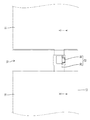
本実施例における板状導電路10は、主に自動車の車内配線に用いられるものである。板状導電路10は、導電性を有する複数の板状導電部材11が、板状導電部材11のそれぞれに設けられた端子部12により互いに接続されてなる。板状導電路10は、例えば動作用電力等の比較的大きい電流を伝達する電力用の導電路として使用したり、複数の電装部品とバッテリとを電気的に接続するためのアース用の導電路として使用することができる。アース用の導電路として使用する場合には、板状導電路10は車体の壁面の車室側に沿うように配される。板状導電路10は、全体として一方向に長い帯状の導電路であってり、任意の箇所に分岐部を有する幹線であったりすることができる。板状導電路10の長さ寸法等は、車両の配索経路に沿うように任意の寸法に設定される。
<Example 1>
Hereinafter, an embodiment embodying the present invention will be described in detail with reference to FIGS. 1 to 9.
The plate-shaped
以下、各構成部材において、他の板状導電部材11に対する接続方向の前側(図1の左下側の板状導電部材11においては右斜め上側、右上側の板状導電部材11においては左斜め下側)をそれぞれ前方、反対側を後方とし、また、図1の上側を表方、下側を裏方として説明する。
Hereinafter, in each component, the front side in the connection direction with respect to the other plate-shaped conductive member 11 (the plate-shaped
板状導電部材11は、金属製(アルミニウムまたはアルミニウム合金等)の平らで薄い板材であり、所定の幅寸法を有した帯状をなしている。板状導電部材11は、広い面積を有することにより、良好な放熱性を発揮することができる。
The plate-shaped
板状導電部材11は、絶縁部材13で覆われて絶縁・保護されている。絶縁部材13は柔軟性を有するものが望ましく、樹脂シート(PVCシート等)や収縮チューブを用いることができる。
The plate-shaped
端子部12は、板状導電部材11に一体に設けられている。端子部12は、板状導電部材11の幅方向における中心よりも端に寄った位置に配されている。本実施例では、一方の板状導電部材11の端子部12は幅方向における中心よりも右端寄りに位置し、他方の板状導電部材11の端子部12は中心よりも左端寄りに位置している。これにより、一方の板状導電部材11の端子部12と他方の板状導電部材11の端子部12とを接続した状態では、両板状導電部材11が幅方向にずれないで直線状に配される。
The
端子部12は、互いに接続される雄型の端子部12(以後、雄型端子部20と称する)と雌型の端子部12(以後、雌型端子部30と称する)とを備えている。 雄型端子部20は、図5に示すように、前方に突出する突片部21を有している。突片部21は、板状導電部材11の板面と略平行をなしている。突片部21の前端における左右両角部は、斜めに切り落とされた形状をなしている。
The
突片部21は、図4に示すように、雌型端子部30の箱部31に挿入され、雌型端子部30の弾性接触部32に押圧される。突片部21には、雌型端子部30の弾性接触部32に押圧される押圧部22が設けられている。押圧部22は、突片部21の裏面側に突出して設けられている。押圧部22は、突片部21の板厚寸法と同程度の突出寸法を有している。押圧部22は、平面視、横長(幅方向に長い)方形状をなし、突片部21の前後方向における中心よりも前端寄りの位置に設けられている。なお、押圧部22の表面側は窪みとなっている。
As shown in FIG. 4, the
雄型端子部20は、図5に示すように、突片部21が板状導電部材11の表側に一段ずれて配されるように段差状に屈曲した形状をなしている。
雄型端子部20は、板状導電部材11の端縁から板状導電部材11と同一板面上で前方に突出する基部23と、基部23の前端縁から表側へ立ち上がる中間部24と、を有し、中間部24の表端縁から突片部21が前方に突出している。中間部24は、基部23に対して略直角をなしている。雄型端子部20は、図6に示すように、全体(基部23、中間部24及び突片部21)にわたって幅寸法が略一定とされている。
As shown in FIG. 5, the
The
雄型端子部20は、板状導電部材11の端部において板状導電部材11と一体的に打ち抜かれた端子構成部(図示せず)によって構成されている。雄型端子部20の端子構成部は、板状導電部材11の幅内に収まっている。
The
雌型端子部30は、雄型端子部20の突片部21が挿入される箱部31と、箱部31内に挿入された突片部(相手側)21に弾性的に接触する弾性接触部32と、を備えている。
The
箱部31は、全体として偏平(横長の長方形状)な角筒状をなし、前後方向に開口している。箱部31は、底部33と、底部33の左右両側に立ち上がる一対の側部34F,34Sと、底部33と対向配置される天井部35とを備えている。
The
底部33は、図4に示すように、板状導電部材11と段差なく連なっている。底部33には、弾性接触部32の過度の撓みを防止する過度撓み防止部36が設けられている。一対の側部34F,34Sは、底部33に対して略直角をなしている(図8参照)。天井部35には、箱部31の内側に一段(板厚寸法と同程度の寸法)膨出した膨出部37が設けられている。膨出部37の外側(表側)は窪んでいる。
As shown in FIG. 4, the
膨出部37は、天井部35の大部分に形成されている。膨出部37の面積は、図4に示すように、雄型端子部20の押圧部22の面積より大きくされている。膨出部37は、図2に示すように、平面視、前後方向に長い方形状をなしている。
The bulging
天井部35は、第1側部34Fの端縁から底部33と略平行をなすように屈曲され、先端が第2側部34Sの端縁に係止している(図7参照)。
天井部35の先端縁には、第2側部34Sの端縁に係止する係止部38が突設されている。係止部38は、天井部35の前後方向における中心部に位置している。係止部38は、第2側部34Sの端縁に表側から当接し、天井部35が箱部31の内側に変位することを防いでいる。
The
A locking
第2側部34Sの端縁には、天井部35側に屈曲されて天井部35の表側に被さる掛け止め部39が設けられている(図7参照)。掛け止め部39は、第2側部34Sの前後に一対が設けられている。一対の掛け止め部39の間は、天井部35の係止部38が当接する受け部41となっている。
At the edge of the
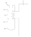
箱部31は、板状導電部材11の端部において板状導電部材11と一体的に打ち抜かれた端子構成部50によって構成されている。端子構成部50は、図9に示すように、加工前の展開状態では、全体として板状導電部材11の端縁に沿う長方形状をなすとともに、板状導電部材11の幅内におさまっている。
The
端子構成部50のうち底部33を構成する部分(以後、底部構成部51と称する)は、板状導電部材11の端縁から前方に突出している。第1側部34Fを構成する部分(以後、第1側部構成部52と称する)及び第2側部34Sを構成する部分(以後、第2側部構成部53と称する)は底部構成部51の左右両側に連なっている。第1側部構成部52及び天井部35を構成する部分(以後、天井部構成部54と称する)は、板状導電部材11の幅方向における中央側に配され、第2側部構成部53は、板状導電部材11の幅方向における端側に配されている。
The portion of the
弾性接触部32は、箱部31とは異種の金属材料(銅、銅合金またはステンレス等)によって構成されている。弾性接触部32は、図7に示すように、箱部31とは別に製造され、かしめや嵌め込み等、任意の固着手段によって箱部31と一体化されている。
The
弾性接触部32は、図4に示すように、箱部31と一体化した状態において底部33から立ち上がる脚部42と、雄型端子部20の突片部21に接触する接触部43とを備えている。脚部42は、底部33に対して傾斜し、接触部43は、天井部35と略平行をなしている。接触部43のうち天井部35と対向する側には、天井部35側に突出する突出部44が設けられている。
As shown in FIG. 4, the
弾性接触部32は、箱部31と一体化した状態では、前端側が基端、後端側が自由端の片持ち状をなしている。弾性接触部32の自由端は、過度撓み防止部36の表側に位置している。弾性接触部32は、図7に示すように、基端側の幅寸法が大きく、自由端側の幅寸法が小さくされている。弾性接触部32の幅寸法は、自由端に向かって次第に減じている。
When the
次に、本実施例における板状導電部材11の接続作業の一例を説明する。
一方の板状導電部材11の端子部12と他方の板状導電部材11の端子部12とを向き合わせて接続する。雄型端子部20の突片部21が箱部31に挿入され、弾性接触部32の脚部42に当接して脚部42の傾斜により天井部35側に案内される。雄型端子部20の突片部21は、弾性接触部32と天井部35との間に入り込む。弾性接触部32は、底部33側へ押圧されて弾性変位する。雄型端子部20の突片部21は、弾性接触部32の弾性復元力によって天井部35に押し付けられる。こうして、端子部12が接続され、板状導電部材11の接続作業が完了する。接続された一対の板状導電部材11は、高さ位置(板厚方向の位置)が揃い、板状導電部材11の表面側で端子部12が接続され、裏面側はフラットになっている。また、接続された一対の板状導電部材11の幅方向の位置が揃い、左右の側縁同士が同一直線状に配される。
Next, an example of the connection work of the plate-shaped
The
次に、上記のように構成された実施例の作用および効果について説明する。
本実施例の板状導電部材11の接続構造は、導電性を有する複数の板状導電部材11が、板状導電部材11のそれぞれに設けられた端子部12により互いに接続されているものである。この構成によれば、電線等の接続部品を使用することなく板状導電部材11を接続することができるから、接続部品の点数を削減することができる。また、電線等、多数の接続部品を接続する作業を省くことができるから、工数を削減することができる。
Next, the actions and effects of the examples configured as described above will be described.
In the connection structure of the plate-shaped
また、端子部12が、加工前の展開状態において板状導電部材11の幅内に収まるように打ち抜かれた端子構成部50により構成されている。ここで、仮に端子構成部が板状導電部材の幅内に収まらない場合には、端子構成部のうち板状導電部材の幅より外側に突出している部分の前後(板状導電部材の側縁に沿う部分)が無駄になる。しかしながら、本実施例の構成によれば、そのような無駄を省くことができる。
Further, the
また、雌型端子部30が、相手側に弾性的に接触する弾性接触部32を有し、板状導電部材11が、アルミニウムまたはアルミニウム合金等の金属材料によって構成され、弾性接触部32が、銅、銅合金またはステンレス等の金属材料によって構成されている。ここで、仮に弾性接触部がアルミニウムまたはアルミニウム合金からなる場合には、弾性接触部が突片部を天井部に押し付ける力(弾性力)が不足する虞がある。しかしながら、弾性接触部32が、銅、銅合金またはステンレス等の金属材料によって構成されているから、相手側に対する接触圧を十分に確保することができる。したがって、板状導電部材11の軽量化と端子部12の接続信頼性の確保とを両立することができる。
Further, the
<実施例2>
次に、本発明を具体化した実施例2に係る板状導電路60を図10〜図12によって説明する。
本実施例の板状導電路60は、板状導電部材11が板厚方向に間をあけて複数配置されている点で、実施例1とは相違する。なお、実施例1と同様の構成には同一符号を付して重複する説明を省略する。
<Example 2>
Next, the plate-shaped
The plate-shaped
本実施例に係る板状導電路60は、複数(本実施例では2)の板状導電部材11が板厚方向に間をあけて配置されている。2枚の板状導電部材11は、絶縁部材13で絶縁された状態で重ねられ、また絶縁部材13で全体が被覆されて保護されている。
In the plate-shaped
板状導電部材11は、実施例1と同様、アルミニウムまたはアルミニウム合金等の金属材料によって構成されている。表裏に重ねられる2枚の板状導電部材11は、幅寸法及び長さ寸法が同等とされている。
The plate-shaped
表裏に重ねられた2枚の板状導電部材11と、絶縁部材13とを有する導電部材61は、実施例1と同様、端子部12により互いに接続されている。端子部12は、導電部材61に備えられた複数の板状導電部材11において、互いに幅方向の位置がずれるように設けられている。本実施例では、一方の板状導電部材11の端子部12は、幅方向における端側に、他方の板状導電部材11の端子部12は、幅方向における他端側に設けられている。
The two plate-shaped
端子部12は、実施例1と同様、互いに接続される雄型端子部20と雌型端子部30とを備えている。本実施例では、一方の導電部材61に雄型端子部20、他方の導電部材61に雌型端子部30が設けられている。雄型端子部20及び雌型端子部30は、実施例1と同様の構成とされている。
Similar to the first embodiment, the
雄型端子部20は、導電部材61において、幅方向に対称な位置に配されている。導電部材61の表側の雄型端子部20と裏側の雄型端子部20とは、板状導電部材11の高さ位置のずれと同じだけ、突片部21の高さ位置がずれている。
The
雌型端子部30は、導電部材61において幅方向に対称な形状となっている。詳しくは、導電部材61の一対の雌型端子部30は、いずれも第1側部34Fが幅方向の中心側に、第2側部34Sが幅方向の外側に配されている。
The
雌型端子部30は、実施例1と同様、加工前の展開状態において板状導電部材11の幅内に収まるように打ち抜かれた端子構成部50により構成されている。導電部材61の雌型端子部30の端子構成部50は、対称な形状をなしている。いずれの端子構成部50も、図9及び図12に示すように、第1側部構成部52及び天井部構成部54が幅方向の中心側に配され、第2側部構成部53が幅方向の端側に配されている。
Similar to the first embodiment, the
本実施例における板状導電路60は、一方の導電部材61の端子部12と他方の導電部材61の端子部12とを向き合わせて、端子部12を接続することにより接続される。導電部材61の表側の板状導電部材11の端子部12同士、裏側の板状導電部材11の端子部12同士が、それぞれ接続される。導電部材61が接続された状態では、表側の板状導電部材11同士の高さ位置(板厚方向の位置)、裏側の板状導電部材11同士の高さ位置がそれぞれ揃っている。
The plate-shaped
以上のように本実施例においては、実施例1と同様、複数の板状導電部材11が、板状導電部材11のそれぞれに設けられた端子部12により互いに接続されているから、電線等の接続部品を使用することなく板状導電部材11を接続することができ、接続部品の点数を削減することができる。
As described above, in the present embodiment, as in the first embodiment, since the plurality of plate-shaped
<実施例3>
次に、本発明を具体化した実施例3に係る板状導電路70を図13〜図19によって説明する。
本実施例の板状導電路70は、複数(本実施例では2)の端子部12が接続端子Tを介して接続されている点で、実施例1とは相違する。なお、実施例1と同様の構成には同一符号を付して重複する説明を省略する。
<Example 3>
Next, the plate-shaped
The plate-shaped
本実施例の板状導電路70は、実施例1と同様、板状導電部材11が、板状導電部材11のそれぞれに設けられた端子部12により互いに接続されている。板状導電部材11は、実施例1と同様、アルミニウムまたはアルミニウム合金等の金属材料によって構成されている。互いに接続される板状導電部材11の端子部12は、いずれも雄型端子部20とされている。雄型端子部20の構造は、実施例1と同様である。
In the plate-shaped
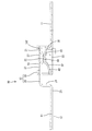
接続端子Tは、互いに接続される端子部12のうち一方が接続される第1接続部71と他方が接続される第2接続部72とを有している。接続端子Tは、一方の端子部12と他方の端子部12との間を中継ぎする中継端子である。
The connection terminal T has a
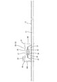
接続端子Tは、図17に示すように、全体として偏平な箱型の筒状をなして前後方向に開口する端子本体部73を有している。端子本体部73の前後両端部に、第1接続部71及び第2接続部72が設けられている。第1接続部71及び第2接続部72は、実施例1の雌型端子部30と同様の構成を有している。
As shown in FIG. 17, the connection terminal T has a
端子本体部73は、雌型端子部30の箱部31と同様、底部74と、一対の側部(第1側部75F及び第2側部75S)と、天井部76とを有し、内部には弾性接触部77が設けられている。弾性接触部77は、端子本体部73の前後両端部に設けられ、それぞれ端子本体部73の前端及び後端から内側(前後方向の中心側)に屈曲された片持ち状をなしている(図16参照)。なお、第1接続部71の掛け止め部78と第2接続部72の掛け止め部78とは、端子本体部73の中心部において連なっている。
The
端子本体部73には、雄型端子部20の突片部21の先端を止めるストッパ部79が設けられている(図16参照)。ストッパ部79は、端子本体部73の前後方向の中心部(第1接続部71と第2接続部72との間)に設けられ、天井部76から内側に略直角に突出している。ストッパ部79は、第1接続部71側と第2接続部72側とに若干離れて一対が設けられている。一対のストッパ部79は、幅方向の一端側と他端側とにずれた位置に配されている(図18参照)。
The
本実施例における板状導電路70は、一方の板状導電部材11の端子部12と他方の板状導電部材11の端子部12とをそれぞれ接続端子Tに接続することにより接続される。板状導電部材11の端子部12を接続端子Tに接続すると、実施例1の端子部12同士の接続と同様、雄型端子部20の突片部21が、弾性接触部77と天井部76との間に入り込み、弾性接触部77の弾性復元力によって天井部76に押し付けられる。また、突片部21の先端が、ストッパ部79に突き当たってそれ以上の挿入が防がれる。こうして、板状導電部材11の端子部12は、接続端子Tの第1接続部71及び第2接続部72にそれぞれ接続される。接続端子Tを介して接続された板状導電部材11同士は、図15に示すように、高さ位置(板厚方向の位置)が揃い、また、接続端子Tの底部74と板状導電部材11とが同じ高さ位置に配される。
The plate-shaped
以上のように本実施例においては、実施例1と同様、複数の板状導電部材11が、板状導電部材11のそれぞれに設けられた端子部12により互いに接続されているから、電線等の接続部品を使用することなく板状導電部材11を接続することができ、接続部品の点数を削減することができる。加えて、端子部12が、接続端子Tを介して接続されているから、端子部12を同形状にすることができる。
As described above, in the present embodiment, as in the first embodiment, since the plurality of plate-shaped
<実施例4>
次に、本発明を具体化した実施例4に係る板状導電路80を図20によって説明する。
本実施例の板状導電路80は、板状導電部材11が板厚方向に間をあけて複数配置されている点で、実施例3とは相違する。なお、実施例3と同様の構成には同一符号を付して重複する説明を省略する。
<Example 4>
Next, the plate-shaped
The plate-shaped
本実施例に係る板状導電路80は、複数(本実施例では2)の板状導電部材11が板厚方向に間をあけて配置されている。2枚の板状導電部材11は、絶縁部材13で絶縁された状態で重ねられ、また絶縁部材13で全体が被覆されて保護されている。
In the plate-shaped
板状導電部材11は、実施例3と同様、アルミニウムまたはアルミニウム合金等の金属材料によって構成されている。表裏に重ねられる2枚の板状導電部材11は、幅寸法及び長さ寸法が同等とされている。
The plate-shaped
表裏に重ねられた2枚の板状導電部材11と、絶縁部材13とを有する導電部材81は、実施例3と同様、端子部12を介して互いに接続されている。端子部12は、導電部材81に備えられた複数の板状導電部材11において、互いに幅方向の位置がずれるように設けられている。本実施例では、一方の板状導電部材11の端子部12は、幅方向における一端側に、他方の板状導電部材11の端子部12は、幅方向における他端側に設けられている。
Similar to the third embodiment, the two plate-shaped
端子部12は、実施例3と同様、いずれも雄型端子部20とされている。一の導電部材81に設けられた一対の雄型端子部20は同形状をなし、幅方向に対称な位置に配されている。表側の雄型端子部20と裏側の雄型端子部20とでは、板状導電部材11の高さ位置のずれと同じだけ、突片部21の高さ位置がずれている。
また、接続端子Tは、実施例3と同様の構成とされている。
The
Further, the connection terminal T has the same configuration as that of the third embodiment.
本実施例における板状導電路80は、一方の導電部材81の端子部12と他方の導電部材81の端子部12とをそれぞれ接続端子Tに接続することにより接続される。導電部材81の表側の板状導電部材11の端子部12同士、裏側の板状導電部材11の端子部12同士が、それぞれ接続端子Tを介して接続される。導電部材81が接続された状態では、表側の板状導電部材11同士の高さ位置(板厚方向の位置)、裏側の板状導電部材11同士の高さ位置がそれぞれ揃っている。
The plate-shaped
以上のように本実施例においては、実施例3と同様、導電性を有する複数の板状導電部材11が、板状導電部材11のそれぞれに設けられた端子部12により互いに接続されているから、電線等の接続部品を使用することなく板状導電部材11を接続することができ、接続部品の点数を削減することができる。加えて、端子部12が接続端子Tを介して接続されているから、端子部12を同形状にすることができる。
As described above, in the present embodiment, as in the third embodiment, the plurality of conductive plate-shaped
<他の実施例>
本発明は上記記述及び図面によって説明した実施例に限定されるものではなく、例えば次のような実施例も本発明の技術的範囲に含まれる。
(1)上記実施例では、端子部12が板状導電部材11に一体に設けられているが、これに限らず、端子部を別体で形成し、板状導電部材に任意の固着手段により取り付けてもよい。
(2)上記実施例では、端子部12が絶縁部材13から露出しているが、これに限らず、端子部をコネクタハウジング等に収容してもよい。
(3)上記実施例では、一の板状導電部材11に一の端子部12のみが設けられているが、これに限らず、一の板状導電部材に複数の端子部を設け、一の板状導電部材に2以上の板状導電部材を接続してもよい。
(4)上記実施例では、板状導電部材11に、他の板状導電部材11との接続に用いられる端子部12が設けられているが、これに加えて、板状導電部材に、電線等に圧着される端子部を一体に設けても良い。
(5)上記実施例では、概ね同形状をなす板状導電部材11を接続する場合について説明したが、これに限らず、形状(長さ寸法や幅寸法)が異なる板状導電部材を接続してもよい。
(6)上記実施例2では、導電部材61の端子部12が、一方は雄型端子部20のみ、他方は雌型端子部30のみとされているが、これに限らず、一の導電部材に、雄型の端子部と雌型の端子部とを混在して設けても良い。
(7)上記実施例2,4では、導電部材に2枚の板状導電部材11が備えられているが、これに限らず、3枚以上の板状導電部材を備えるものとしてもよい。
(8)上記実施例3,4では、接続端子Tが、一対の端子部12を中継する中継端子とされているが、これに限らず、例えば接続端子は、3以上の端子部をジョイントするジョイント端子であってもよい。
<Other Examples>
The present invention is not limited to the examples described by the above description and drawings, and for example, the following examples are also included in the technical scope of the present invention.
(1) In the above embodiment, the
(2) In the above embodiment, the
(3) In the above embodiment, only one
(4) In the above embodiment, the plate-shaped
(5) In the above embodiment, the case where the plate-shaped
(6) In the second embodiment, the
(7) In the above Examples 2, 4, although the conductive member is two plate-like
(8) In the above Examples 3 and 4, the connection terminal T is a relay terminal that relays the pair of
T…接続端子
10,60,70,80…板状導電路
11…板状導電部材
12…端子部
13…絶縁部材
20…雄型端子部(雄型の端子部)
30…雌型端子部(雌型の端子部)
32…弾性接触部
50…端子構成部
61,81…導電部材
T ...
30 ... Female terminal (female terminal)
32 ...
Claims (6)
前記端子部が、互いに接続される雄型の端子部と雌型の端子部とを備え、
前記雌型の端子部が、前記雄型の端子部が挿入される箱部を有し、前記箱部は、前記板状導電部材の長さ方向の先端につながって前記板状導電部材の幅内に設けられ、加工前の展開状態において前記板状導電部材の幅内に収まるように打ち抜かれた端子構成部により構成されている板状導電部材の接続構造。 A plurality of plate-shaped conductive members having conductivity are connected to each other by terminal portions provided on each of the plate-shaped conductive members.
The terminal portion includes a male terminal portion and a female terminal portion that are connected to each other.
The female terminal portion has a box portion into which the male terminal portion is inserted, and the box portion is connected to the tip in the length direction of the plate-shaped conductive member and is connected to the width of the plate-shaped conductive member. A connection structure of a plate-shaped conductive member provided inside and composed of a terminal component punched out so as to fit within the width of the plate-shaped conductive member in the unfolded state before processing.
前記端子部が、前記板状導電部材の板厚方向における一方の側に一段ずれて配されるように段差状に屈曲した突片部を備え、
複数の前記端子部が、接続端子を介して接続され、
前記接続端子は、前記突片部が挿入される箱型をなし、
前記接続端子を介して接続された前記板状導電部材同士の板厚方向の位置が揃うとともに、前記接続端子の底部と前記板状導電部材とが同じ高さ位置に配される板状導電部材の接続構造。 A plurality of plate-shaped conductive members having conductivity are connected to each other by terminal portions provided on each of the plate-shaped conductive members.
The terminal portion is provided with a projecting piece portion that is bent in a stepped shape so that the terminal portion is arranged one step away from one side in the plate thickness direction of the plate-shaped conductive member.
A plurality of the terminal portions are connected via the connection terminal,
The connection terminal has a box shape into which the projecting piece is inserted.
The plate-shaped conductive members connected via the connection terminal are aligned in the plate thickness direction, and the bottom of the connection terminal and the plate-shaped conductive member are arranged at the same height position. Connection structure.
複数の前記端子部が、接続端子を介して接続され、
前記接続端子は、複数の前記端子部を内部に挿入可能な端子本体部を有し、
前記端子本体部は、筒状をなし、
前記端子本体部自身に、前記端子本体部の内部に挿入された前記端子部それぞれに弾性的に接触する弾性接触部と、前記端子本体部に挿入された前記端子部それぞれの先端を止めるストッパ部と、が一体に設けられ、
前記ストッパ部は、前記端子本体部の天井部から内側に突出する形状であり、 複数の前記端子部は、それぞれ、前記弾性接触部と前記天井部との間に入り込み、前記弾性接触部の弾性復元力によって前記天井部に押し当てられる板状導電部材の接続構造。 A plurality of plate-shaped conductive members having conductivity are connected to each other by terminal portions provided on each of the plate-shaped conductive members.
A plurality of the terminal portions are connected via the connection terminal,
The connection terminal has a terminal body portion into which a plurality of the terminal portions can be inserted.
The terminal body has a tubular shape.
An elastic contact portion that elastically contacts each of the terminal portions inserted inside the terminal main body portion itself, and a stopper portion that stops the tips of the terminal portions inserted into the terminal main body portion. And are provided integrally,
The stopper portion has a shape that protrudes inward from the ceiling portion of the terminal body portion, and the plurality of terminal portions each enter between the elastic contact portion and the ceiling portion, and the elasticity of the elastic contact portion is achieved. A connection structure of a plate-shaped conductive member that is pressed against the ceiling by a restoring force.
前記板状導電部材が、アルミニウムまたはアルミニウム合金等の金属材料によって構成され、
前記弾性接触部が、銅、銅合金またはステンレス等の金属材料によって構成されている請求項1に記載の板状導電部材の接続構造。 The terminal portion has an elastic contact portion that elastically contacts the mating side.
The plate-shaped conductive member is made of a metal material such as aluminum or an aluminum alloy.
The connection structure for a plate-shaped conductive member according to claim 1, wherein the elastic contact portion is made of a metal material such as copper, a copper alloy, or stainless steel.
前記板状導電部材を覆う絶縁部材と、
請求項1から請求項4のいずれか一項に記載の板状導電部材の接続構造と、
を備えている板状導電路。 With a plurality of plate-shaped conductive members having conductivity,
An insulating member that covers the plate-shaped conductive member and
The connection structure of the plate-shaped conductive member according to any one of claims 1 to 4.
A plate-shaped conductive path equipped with.
前記絶縁部材が、前記複数の板状導電部材の間を絶縁している請求項5に記載の板状導電路。 A plurality of the plate-shaped conductive members are arranged with a gap in the plate thickness direction.
The plate-shaped conductive path according to claim 5, wherein the insulating member insulates between the plurality of plate-shaped conductive members.
Priority Applications (4)
| Application Number | Priority Date | Filing Date | Title |
|---|---|---|---|
| JP2017022928A JP6913278B2 (en) | 2017-02-10 | 2017-02-10 | Connection structure of plate-shaped conductive members and plate-shaped conductive path |
| CN201880008554.2A CN110326166B (en) | 2017-02-10 | 2018-01-22 | Connection structure of plate-shaped conductive member and plate-shaped conductive path |
| US16/484,498 US10916872B2 (en) | 2017-02-10 | 2018-01-22 | Plate-like conductive member connection structure and plate-like conductive path |
| PCT/JP2018/001756 WO2018147055A1 (en) | 2017-02-10 | 2018-01-22 | Plate-shaped electric conductive member connection structure and plate-shaped electric conduction path |
Applications Claiming Priority (1)
| Application Number | Priority Date | Filing Date | Title |
|---|---|---|---|
| JP2017022928A JP6913278B2 (en) | 2017-02-10 | 2017-02-10 | Connection structure of plate-shaped conductive members and plate-shaped conductive path |
Publications (3)
| Publication Number | Publication Date |
|---|---|
| JP2018129252A JP2018129252A (en) | 2018-08-16 |
| JP2018129252A5 JP2018129252A5 (en) | 2019-07-18 |
| JP6913278B2 true JP6913278B2 (en) | 2021-08-04 |
Family
ID=63107345
Family Applications (1)
| Application Number | Title | Priority Date | Filing Date |
|---|---|---|---|
| JP2017022928A Active JP6913278B2 (en) | 2017-02-10 | 2017-02-10 | Connection structure of plate-shaped conductive members and plate-shaped conductive path |
Country Status (4)
| Country | Link |
|---|---|
| US (1) | US10916872B2 (en) |
| JP (1) | JP6913278B2 (en) |
| CN (1) | CN110326166B (en) |
| WO (1) | WO2018147055A1 (en) |
Families Citing this family (2)
| Publication number | Priority date | Publication date | Assignee | Title |
|---|---|---|---|---|
| US11264752B1 (en) * | 2020-11-09 | 2022-03-01 | Aptiv Technologies Limited | Planar terminal connector having an additional contact spring |
| US20220368052A1 (en) * | 2021-05-12 | 2022-11-17 | Aptiv Technologies Limited | High voltage (hv) terminal frame |
Family Cites Families (37)
| Publication number | Priority date | Publication date | Assignee | Title |
|---|---|---|---|---|
| US3636505A (en) * | 1970-03-11 | 1972-01-18 | Amp Inc | Electrical pin with tab receptacles and method of making same |
| US4462657A (en) * | 1980-04-18 | 1984-07-31 | Eaton Corporation | Compliant electrical connector for flat conductors |
| JPH0722077A (en) * | 1993-07-02 | 1995-01-24 | Fujitsu Ltd | Connection structure of power feeder line |
| JPH07106001A (en) | 1993-10-04 | 1995-04-21 | Oki Electric Ind Co Ltd | Bus bar |
| GB9420531D0 (en) * | 1994-10-12 | 1994-11-30 | Gorevan Marco | Smoke alarm battery adaptor |
| US5588884A (en) * | 1995-09-08 | 1996-12-31 | Packard Hughes Interconnect Company | Stamped and formed contacts for a power connector |
| JPH09140030A (en) * | 1995-11-17 | 1997-05-27 | Yazaki Corp | Bus bar |
| JP3147794B2 (en) * | 1996-12-12 | 2001-03-19 | 住友電装株式会社 | Electrical connection structure of electrical junction box |
| JP2000067943A (en) * | 1998-08-19 | 2000-03-03 | Harness Syst Tech Res Ltd | Electrically connecting component |
| JP3424632B2 (en) | 2000-01-14 | 2003-07-07 | 住友電装株式会社 | Method of using relay terminal connection structure and electric connection box |
| US6416340B2 (en) * | 2000-05-04 | 2002-07-09 | Christopher E. Schaefer | Single blade terminal power connector system |
| JP2002204518A (en) | 2001-01-09 | 2002-07-19 | Auto Network Gijutsu Kenkyusho:Kk | Bus-bar connecting structure |
| JP2004096950A (en) * | 2002-09-03 | 2004-03-25 | Sumitomo Wiring Syst Ltd | Conductive material |
| JP3861777B2 (en) | 2002-09-04 | 2006-12-20 | 住友電装株式会社 | Conductive material |
| JP2004104946A (en) | 2002-09-11 | 2004-04-02 | Sumitomo Wiring Syst Ltd | Bus bar |
| DE102004015345A1 (en) * | 2004-03-30 | 2005-10-27 | Kostal Kontakt Systeme Gmbh | Electrical socket contact for high current applications |
| JP2007250362A (en) * | 2006-03-16 | 2007-09-27 | Toyota Motor Corp | Connector structure and connector type terminal board structure |
| JP5105194B2 (en) * | 2008-11-04 | 2012-12-19 | 住友電装株式会社 | Board connector |
| EP2451016B1 (en) * | 2009-07-03 | 2018-11-21 | Yazaki Corporation | Female terminal |
| US8398442B2 (en) * | 2009-09-08 | 2013-03-19 | Yazaki Corporation | Terminal fitting and a method for assembling the same |
| CH702863B1 (en) * | 2010-03-30 | 2014-12-15 | Multi Holding Ag | Connecting element. |
| US8628875B2 (en) * | 2010-04-16 | 2014-01-14 | Samsung Sdi Co., Ltd. | Battery module with multi-level connector |
| CN201781088U (en) * | 2010-09-02 | 2011-03-30 | 番禺得意精密电子工业有限公司 | Electric connector |
| WO2012077465A1 (en) * | 2010-12-07 | 2012-06-14 | 株式会社オートネットワーク技術研究所 | Terminal-attached plate, plate assembly, and cell module |
| DE102011050364B4 (en) * | 2011-05-13 | 2013-08-29 | Tyco Electronics Amp Gmbh | Plug contact element and plug contact arrangement for the transmission of frequencies in the gigahertz range |
| JP5772524B2 (en) * | 2011-11-11 | 2015-09-02 | 株式会社オートネットワーク技術研究所 | Battery wiring module |
| JP5699942B2 (en) * | 2012-01-12 | 2015-04-15 | 株式会社オートネットワーク技術研究所 | Electric wire with terminal |
| EP2615692B1 (en) * | 2012-01-13 | 2018-04-04 | Tyco Electronics UK Limited | Conductive connection assembly, method for manufacturing the same and kit for a body |
| JP5871729B2 (en) * | 2012-06-28 | 2016-03-01 | 日本航空電子工業株式会社 | Housingless connector |
| JP6026961B2 (en) * | 2013-06-18 | 2016-11-16 | 豊田合成株式会社 | Battery cell, battery unit and battery stack |
| JP5708837B1 (en) * | 2014-02-06 | 2015-04-30 | 第一精工株式会社 | Connector terminal |
| JP2016111825A (en) | 2014-12-05 | 2016-06-20 | 矢崎総業株式会社 | Ground member for vehicle and automobile including the same |
| JP2016120901A (en) * | 2014-12-24 | 2016-07-07 | 株式会社オートネットワーク技術研究所 | Automotive power feeder |
| WO2016104101A1 (en) | 2014-12-24 | 2016-06-30 | 株式会社オートネットワーク技術研究所 | Power supply device for automobile |
| JP6500761B2 (en) * | 2015-12-03 | 2019-04-17 | 株式会社オートネットワーク技術研究所 | Electrical connection device |
| JP6951413B2 (en) * | 2016-07-18 | 2021-10-20 | ストーブリ エレクトリカル コネクターズ アーゲー | Connection element |
| US10389055B1 (en) * | 2018-06-20 | 2019-08-20 | Delphia Technologies, Llc | Electrical connector assembly |
-
2017
- 2017-02-10 JP JP2017022928A patent/JP6913278B2/en active Active
-
2018
- 2018-01-22 CN CN201880008554.2A patent/CN110326166B/en active Active
- 2018-01-22 WO PCT/JP2018/001756 patent/WO2018147055A1/en active Application Filing
- 2018-01-22 US US16/484,498 patent/US10916872B2/en active Active
Also Published As
| Publication number | Publication date |
|---|---|
| WO2018147055A1 (en) | 2018-08-16 |
| CN110326166B (en) | 2021-05-11 |
| CN110326166A (en) | 2019-10-11 |
| US10916872B2 (en) | 2021-02-09 |
| JP2018129252A (en) | 2018-08-16 |
| US20200006881A1 (en) | 2020-01-02 |
Similar Documents
| Publication | Publication Date | Title |
|---|---|---|
| US10673159B2 (en) | Grounded electrical connector | |
| TWI403032B (en) | Spring extended female terminal | |
| TWI684313B (en) | Battery connection module | |
| TWI569518B (en) | Electrical connector | |
| US8851938B2 (en) | Terminal connection structure | |
| US9716331B2 (en) | Female contact and power connector | |
| US11005205B2 (en) | Stable female terminal and stable male-female plug-in electrical connector using same | |
| TW201014062A (en) | Electric connector | |
| JP7107708B2 (en) | connector | |
| JP6913278B2 (en) | Connection structure of plate-shaped conductive members and plate-shaped conductive path | |
| US11177601B2 (en) | Terminal having a conductor and a spring | |
| JP4509866B2 (en) | Terminal fitting | |
| US6416366B2 (en) | Terminal metal fitting | |
| TWI244811B (en) | A connector and connector assembly | |
| JP6154430B2 (en) | Female terminal fitting and connector having the same | |
| JP5720526B2 (en) | Terminal fitting | |
| JP4482391B2 (en) | Busbar and terminal connection structure | |
| CN110168819B (en) | Joint connector | |
| JP3444398B2 (en) | Terminal fitting connection structure and male terminal fittings | |
| JP3166588B2 (en) | Short structure of female terminal fitting | |
| JP2003032840A (en) | Electrical connection box | |
| JP4414845B2 (en) | connector | |
| JP5564277B2 (en) | Female terminal fitting | |
| JP4600277B2 (en) | Female terminal structure | |
| JPH0141180Y2 (en) |
Legal Events
| Date | Code | Title | Description |
|---|---|---|---|
| A621 | Written request for application examination |
Free format text: JAPANESE INTERMEDIATE CODE: A621 Effective date: 20190530 |
|
| A521 | Request for written amendment filed |
Free format text: JAPANESE INTERMEDIATE CODE: A523 Effective date: 20190612 |
|
| A131 | Notification of reasons for refusal |
Free format text: JAPANESE INTERMEDIATE CODE: A131 Effective date: 20200507 |
|
| A521 | Request for written amendment filed |
Free format text: JAPANESE INTERMEDIATE CODE: A523 Effective date: 20200622 |
|
| A131 | Notification of reasons for refusal |
Free format text: JAPANESE INTERMEDIATE CODE: A131 Effective date: 20201117 |
|
| A521 | Request for written amendment filed |
Free format text: JAPANESE INTERMEDIATE CODE: A523 Effective date: 20210108 |
|
| A131 | Notification of reasons for refusal |
Free format text: JAPANESE INTERMEDIATE CODE: A131 Effective date: 20210316 |
|
| A521 | Request for written amendment filed |
Free format text: JAPANESE INTERMEDIATE CODE: A523 Effective date: 20210517 |
|
| TRDD | Decision of grant or rejection written | ||
| A01 | Written decision to grant a patent or to grant a registration (utility model) |
Free format text: JAPANESE INTERMEDIATE CODE: A01 Effective date: 20210610 |
|
| A61 | First payment of annual fees (during grant procedure) |
Free format text: JAPANESE INTERMEDIATE CODE: A61 Effective date: 20210623 |
|
| R150 | Certificate of patent or registration of utility model |
Ref document number: 6913278 Country of ref document: JP Free format text: JAPANESE INTERMEDIATE CODE: R150 |