WO2017081919A1 - 提示制御装置及び提示制御方法 - Google Patents
提示制御装置及び提示制御方法 Download PDFInfo
- Publication number
- WO2017081919A1 WO2017081919A1 PCT/JP2016/076242 JP2016076242W WO2017081919A1 WO 2017081919 A1 WO2017081919 A1 WO 2017081919A1 JP 2016076242 W JP2016076242 W JP 2016076242W WO 2017081919 A1 WO2017081919 A1 WO 2017081919A1
- Authority
- WO
- WIPO (PCT)
- Prior art keywords
- control
- presentation
- vehicle
- information
- behavior change
- Prior art date
- Legal status (The legal status is an assumption and is not a legal conclusion. Google has not performed a legal analysis and makes no representation as to the accuracy of the status listed.)
- Ceased
Links
Images








Classifications
-
- B—PERFORMING OPERATIONS; TRANSPORTING
- B60—VEHICLES IN GENERAL
- B60W—CONJOINT CONTROL OF VEHICLE SUB-UNITS OF DIFFERENT TYPE OR DIFFERENT FUNCTION; CONTROL SYSTEMS SPECIALLY ADAPTED FOR HYBRID VEHICLES; ROAD VEHICLE DRIVE CONTROL SYSTEMS FOR PURPOSES NOT RELATED TO THE CONTROL OF A PARTICULAR SUB-UNIT
- B60W50/00—Details of control systems for road vehicle drive control not related to the control of a particular sub-unit, e.g. process diagnostic or vehicle driver interfaces
- B60W50/08—Interaction between the driver and the control system
- B60W50/085—Changing the parameters of the control units, e.g. changing limit values, working points by control input
-
- B—PERFORMING OPERATIONS; TRANSPORTING
- B60—VEHICLES IN GENERAL
- B60K—ARRANGEMENT OR MOUNTING OF PROPULSION UNITS OR OF TRANSMISSIONS IN VEHICLES; ARRANGEMENT OR MOUNTING OF PLURAL DIVERSE PRIME-MOVERS IN VEHICLES; AUXILIARY DRIVES FOR VEHICLES; INSTRUMENTATION OR DASHBOARDS FOR VEHICLES; ARRANGEMENTS IN CONNECTION WITH COOLING, AIR INTAKE, GAS EXHAUST OR FUEL SUPPLY OF PROPULSION UNITS IN VEHICLES
- B60K35/00—Instruments specially adapted for vehicles; Arrangement of instruments in or on vehicles
- B60K35/20—Output arrangements, i.e. from vehicle to user, associated with vehicle functions or specially adapted therefor
- B60K35/21—Output arrangements, i.e. from vehicle to user, associated with vehicle functions or specially adapted therefor using visual output, e.g. blinking lights or matrix displays
- B60K35/22—Display screens
-
- B—PERFORMING OPERATIONS; TRANSPORTING
- B60—VEHICLES IN GENERAL
- B60K—ARRANGEMENT OR MOUNTING OF PROPULSION UNITS OR OF TRANSMISSIONS IN VEHICLES; ARRANGEMENT OR MOUNTING OF PLURAL DIVERSE PRIME-MOVERS IN VEHICLES; AUXILIARY DRIVES FOR VEHICLES; INSTRUMENTATION OR DASHBOARDS FOR VEHICLES; ARRANGEMENTS IN CONNECTION WITH COOLING, AIR INTAKE, GAS EXHAUST OR FUEL SUPPLY OF PROPULSION UNITS IN VEHICLES
- B60K35/00—Instruments specially adapted for vehicles; Arrangement of instruments in or on vehicles
- B60K35/10—Input arrangements, i.e. from user to vehicle, associated with vehicle functions or specially adapted therefor
-
- B—PERFORMING OPERATIONS; TRANSPORTING
- B60—VEHICLES IN GENERAL
- B60K—ARRANGEMENT OR MOUNTING OF PROPULSION UNITS OR OF TRANSMISSIONS IN VEHICLES; ARRANGEMENT OR MOUNTING OF PLURAL DIVERSE PRIME-MOVERS IN VEHICLES; AUXILIARY DRIVES FOR VEHICLES; INSTRUMENTATION OR DASHBOARDS FOR VEHICLES; ARRANGEMENTS IN CONNECTION WITH COOLING, AIR INTAKE, GAS EXHAUST OR FUEL SUPPLY OF PROPULSION UNITS IN VEHICLES
- B60K35/00—Instruments specially adapted for vehicles; Arrangement of instruments in or on vehicles
- B60K35/20—Output arrangements, i.e. from vehicle to user, associated with vehicle functions or specially adapted therefor
- B60K35/28—Output arrangements, i.e. from vehicle to user, associated with vehicle functions or specially adapted therefor characterised by the type of the output information, e.g. video entertainment or vehicle dynamics information; characterised by the purpose of the output information, e.g. for attracting the attention of the driver
-
- B—PERFORMING OPERATIONS; TRANSPORTING
- B60—VEHICLES IN GENERAL
- B60K—ARRANGEMENT OR MOUNTING OF PROPULSION UNITS OR OF TRANSMISSIONS IN VEHICLES; ARRANGEMENT OR MOUNTING OF PLURAL DIVERSE PRIME-MOVERS IN VEHICLES; AUXILIARY DRIVES FOR VEHICLES; INSTRUMENTATION OR DASHBOARDS FOR VEHICLES; ARRANGEMENTS IN CONNECTION WITH COOLING, AIR INTAKE, GAS EXHAUST OR FUEL SUPPLY OF PROPULSION UNITS IN VEHICLES
- B60K35/00—Instruments specially adapted for vehicles; Arrangement of instruments in or on vehicles
- B60K35/20—Output arrangements, i.e. from vehicle to user, associated with vehicle functions or specially adapted therefor
- B60K35/29—Instruments characterised by the way in which information is handled, e.g. showing information on plural displays or prioritising information according to driving conditions
-
- B—PERFORMING OPERATIONS; TRANSPORTING
- B60—VEHICLES IN GENERAL
- B60W—CONJOINT CONTROL OF VEHICLE SUB-UNITS OF DIFFERENT TYPE OR DIFFERENT FUNCTION; CONTROL SYSTEMS SPECIALLY ADAPTED FOR HYBRID VEHICLES; ROAD VEHICLE DRIVE CONTROL SYSTEMS FOR PURPOSES NOT RELATED TO THE CONTROL OF A PARTICULAR SUB-UNIT
- B60W50/00—Details of control systems for road vehicle drive control not related to the control of a particular sub-unit, e.g. process diagnostic or vehicle driver interfaces
- B60W50/08—Interaction between the driver and the control system
- B60W50/14—Means for informing the driver, warning the driver or prompting a driver intervention
-
- B—PERFORMING OPERATIONS; TRANSPORTING
- B60—VEHICLES IN GENERAL
- B60W—CONJOINT CONTROL OF VEHICLE SUB-UNITS OF DIFFERENT TYPE OR DIFFERENT FUNCTION; CONTROL SYSTEMS SPECIALLY ADAPTED FOR HYBRID VEHICLES; ROAD VEHICLE DRIVE CONTROL SYSTEMS FOR PURPOSES NOT RELATED TO THE CONTROL OF A PARTICULAR SUB-UNIT
- B60W50/00—Details of control systems for road vehicle drive control not related to the control of a particular sub-unit, e.g. process diagnostic or vehicle driver interfaces
- B60W50/08—Interaction between the driver and the control system
- B60W50/14—Means for informing the driver, warning the driver or prompting a driver intervention
- B60W50/16—Tactile feedback to the driver, e.g. vibration or force feedback to the driver on the steering wheel or the accelerator pedal
-
- B—PERFORMING OPERATIONS; TRANSPORTING
- B60—VEHICLES IN GENERAL
- B60K—ARRANGEMENT OR MOUNTING OF PROPULSION UNITS OR OF TRANSMISSIONS IN VEHICLES; ARRANGEMENT OR MOUNTING OF PLURAL DIVERSE PRIME-MOVERS IN VEHICLES; AUXILIARY DRIVES FOR VEHICLES; INSTRUMENTATION OR DASHBOARDS FOR VEHICLES; ARRANGEMENTS IN CONNECTION WITH COOLING, AIR INTAKE, GAS EXHAUST OR FUEL SUPPLY OF PROPULSION UNITS IN VEHICLES
- B60K2360/00—Indexing scheme associated with groups B60K35/00 or B60K37/00 relating to details of instruments or dashboards
- B60K2360/16—Type of output information
- B60K2360/175—Autonomous driving
-
- B—PERFORMING OPERATIONS; TRANSPORTING
- B60—VEHICLES IN GENERAL
- B60K—ARRANGEMENT OR MOUNTING OF PROPULSION UNITS OR OF TRANSMISSIONS IN VEHICLES; ARRANGEMENT OR MOUNTING OF PLURAL DIVERSE PRIME-MOVERS IN VEHICLES; AUXILIARY DRIVES FOR VEHICLES; INSTRUMENTATION OR DASHBOARDS FOR VEHICLES; ARRANGEMENTS IN CONNECTION WITH COOLING, AIR INTAKE, GAS EXHAUST OR FUEL SUPPLY OF PROPULSION UNITS IN VEHICLES
- B60K35/00—Instruments specially adapted for vehicles; Arrangement of instruments in or on vehicles
- B60K35/20—Output arrangements, i.e. from vehicle to user, associated with vehicle functions or specially adapted therefor
- B60K35/25—Output arrangements, i.e. from vehicle to user, associated with vehicle functions or specially adapted therefor using haptic output
-
- B—PERFORMING OPERATIONS; TRANSPORTING
- B60—VEHICLES IN GENERAL
- B60K—ARRANGEMENT OR MOUNTING OF PROPULSION UNITS OR OF TRANSMISSIONS IN VEHICLES; ARRANGEMENT OR MOUNTING OF PLURAL DIVERSE PRIME-MOVERS IN VEHICLES; AUXILIARY DRIVES FOR VEHICLES; INSTRUMENTATION OR DASHBOARDS FOR VEHICLES; ARRANGEMENTS IN CONNECTION WITH COOLING, AIR INTAKE, GAS EXHAUST OR FUEL SUPPLY OF PROPULSION UNITS IN VEHICLES
- B60K35/00—Instruments specially adapted for vehicles; Arrangement of instruments in or on vehicles
- B60K35/20—Output arrangements, i.e. from vehicle to user, associated with vehicle functions or specially adapted therefor
- B60K35/26—Output arrangements, i.e. from vehicle to user, associated with vehicle functions or specially adapted therefor using acoustic output
- B60K35/265—Voice
-
- B—PERFORMING OPERATIONS; TRANSPORTING
- B60—VEHICLES IN GENERAL
- B60W—CONJOINT CONTROL OF VEHICLE SUB-UNITS OF DIFFERENT TYPE OR DIFFERENT FUNCTION; CONTROL SYSTEMS SPECIALLY ADAPTED FOR HYBRID VEHICLES; ROAD VEHICLE DRIVE CONTROL SYSTEMS FOR PURPOSES NOT RELATED TO THE CONTROL OF A PARTICULAR SUB-UNIT
- B60W50/00—Details of control systems for road vehicle drive control not related to the control of a particular sub-unit, e.g. process diagnostic or vehicle driver interfaces
- B60W50/08—Interaction between the driver and the control system
- B60W50/14—Means for informing the driver, warning the driver or prompting a driver intervention
- B60W2050/146—Display means
-
- B—PERFORMING OPERATIONS; TRANSPORTING
- B60—VEHICLES IN GENERAL
- B60W—CONJOINT CONTROL OF VEHICLE SUB-UNITS OF DIFFERENT TYPE OR DIFFERENT FUNCTION; CONTROL SYSTEMS SPECIALLY ADAPTED FOR HYBRID VEHICLES; ROAD VEHICLE DRIVE CONTROL SYSTEMS FOR PURPOSES NOT RELATED TO THE CONTROL OF A PARTICULAR SUB-UNIT
- B60W30/00—Purposes of road vehicle drive control systems not related to the control of a particular sub-unit, e.g. of systems using conjoint control of vehicle sub-units
- B60W30/18—Propelling the vehicle
- B60W30/18009—Propelling the vehicle related to particular drive situations
- B60W30/18163—Lane change; Overtaking manoeuvres
-
- G—PHYSICS
- G08—SIGNALLING
- G08G—TRAFFIC CONTROL SYSTEMS
- G08G1/00—Traffic control systems for road vehicles
- G08G1/16—Anti-collision systems
- G08G1/167—Driving aids for lane monitoring, lane changing, e.g. blind spot detection
Definitions
- the present disclosure relates to a presentation control apparatus that controls an information presentation apparatus that is mounted on a vehicle and that presents information to a vehicle occupant, and a presentation control method.
- Patent Document 1 discloses a system that supports driving of a driver by collectively presenting information necessary for lane change to a driver driving the vehicle. . Specifically, in the system disclosed in Patent Document 1, for example, the direction of the lane change, whether to change the lane, whether to change the lane, the waiting time until the lane change, the acceleration / deceleration necessary for changing the lane, Information such as the position of the vehicle is presented to the driver.
- the inventor of the present disclosure has conceived that the contents of acceleration / deceleration or steering control performed by the vehicle control device are presented to the occupant in accordance with the behavior change that occurs in the vehicle. According to such presentation of the operation information of the vehicle control device, the vehicle occupant can feel relieved with respect to the control of the vehicle by the vehicle control device.
- the vehicle control device tries to control the behavior of the vehicle as gently as possible. Therefore, for example, when a large behavior change such as a lane change occurs, the information per time according to the vehicle behavior change is small. For this reason, the vehicle occupant could not imagine the magnitude of the planned behavioral change that would occur in the vehicle from the presentation of information, and could be anxious.
- This disclosure is intended to provide a presentation control device and a presentation control method capable of reducing the anxiety of a vehicle occupant whose behavior is controlled by the vehicle control device.
- a presentation control device that controls presentation of information by an information presentation device directed to an occupant of the vehicle Is a plan acquisition unit that acquires a travel plan showing the details of the vehicle control scheduled by the vehicle control device, and a control target value related to the magnitude of the behavior change included in the travel plan.
- a behavior change determination unit that determines whether or not a preceding threshold corresponding to the control target value is exceeded, and details of control performed by the vehicle control device when the control target value is less than the preceding threshold.
- the vehicle is presented to the occupant by the information presentation device, and the vehicle is based on the travel plan when the control target value exceeds the preceding threshold.
- the control content of the vehicle control device is presented to the occupant. Is temporarily preceded by a change in actual vehicle behavior. As a result, the vehicle occupant can recognize in advance the occurrence of a large behavior change by presenting information through the information presenting device.
- the information presentation shows a large change in a short time, and the content of control by the vehicle control device can be exaggerated and transmitted to the occupant. . Therefore, the occupant can easily imagine the magnitude of the planned behavior change occurring in the vehicle from the information presentation.
- the presentation control device can reduce the anxiety of the vehicle occupant whose behavior is controlled by the vehicle control device.
- a presentation control method for controlling presentation of information by an information presentation device directed to an occupant of the vehicle Obtains a travel plan showing the details of the control of the vehicle scheduled by the vehicle control device, and a control target value related to the magnitude of the behavior change included in the travel plan is the control target It is determined whether or not the preceding threshold corresponding to the value is exceeded, and when the control target value is less than the preceding threshold, the content of the control performed by the vehicle control device is matched with the behavior change that occurs in the vehicle.
- the control executed by the vehicle control device based on the travel plan when the information presenting device presents the occupant and the control target value exceeds the preceding threshold.
- the presentation including that to temporarily prior to the actual behavioral changes.
- the control content of the vehicle control device is presented to the occupant. Is temporarily preceded by a change in actual vehicle behavior. As a result, the vehicle occupant can recognize in advance the occurrence of a large behavior change by presenting information through the information presenting device.
- the information presentation shows a large change in a short time, and the content of control by the vehicle control device can be exaggerated and transmitted to the occupant. . Therefore, the occupant can easily imagine the magnitude of the planned behavior change occurring in the vehicle from the information presentation.
- the presentation control device can reduce the anxiety of the vehicle occupant whose behavior is controlled by the vehicle control device.
- FIG. 1 is a diagram showing a layout around a driver's seat in the own vehicle.
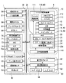
- FIG. 2 is a block diagram showing the overall configuration of the in-vehicle network.
- FIG. 3 is a diagram showing functional blocks constructed in the control circuit of the vehicle control ECU.
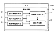
- FIG. 4 is a diagram showing functional blocks constructed in the control circuit of the HCU.
- FIG. 5 is a flowchart showing a threshold adjustment process performed by the behavior change determination unit.
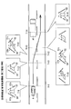
- FIG. 6 is a diagram illustrating an example of a scene in which advance presentation is performed in the first embodiment.
- FIG. 7 is a diagram illustrating a correspondence relationship between vehicle behavior and each progress degree of the GUI in a scene in which advance presentation is performed.
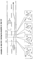
- FIG. 8 is a diagram illustrating an example of a scene in which advance presentation is not performed in the first embodiment.
- FIG. 9 is a diagram showing a correspondence relationship between the vehicle behavior and the progress of each GUI in the scene where the prior presentation is not performed.
- FIG. 10 is a diagram illustrating another example of the scene where the preceding presentation is performed
- FIG. 11 is a diagram illustrating another example of a scene in which advance presentation is not performed.
- FIG. 12 is a flowchart showing a presentation control process performed by the control circuit of the HCU.
- FIG. 13 is a diagram illustrating an example of a scene in which advance presentation is performed in the second embodiment.
- FIG. 14 is a diagram illustrating an example of a scene in which prior presentation is not performed in the second embodiment.
- FIG. 15 is a diagram illustrating another example of a scene in which advance presentation is performed,
- FIG. 16 is a diagram illustrating another example of a scene in which advance presentation is not performed.
- An HCU (HMI (Human Machine Interface) Control Unit) 20 of the first embodiment is an electronic device mounted on the host vehicle A as shown in FIGS. 1 and 2.
- the HCU 20 is one of a plurality of nodes provided in the in-vehicle network 1 mounted on the host vehicle A.
- the in-vehicle network 1 includes an ADAS locator 96, an ITS communication device 97, an external environment recognition system 90, a vehicle control system 60, an HMI system 10, and the like. These components are connected to a communication bus 99 and can exchange information with each other by communication.
- the ADAS (Advanced Driver Assistance Systems) locator 96 includes a GNSS receiver, an inertial sensor such as a gyro sensor, and a memory for storing map data.
- a GNSS (Global Navigation Satellite System) receiver receives positioning signals from a plurality of artificial satellites.
- the ADAS locator 96 measures the position of the host vehicle A by combining the positioning signal received by the GNSS receiver and the measurement result of the inertial sensor.
- the ADAS locator 96 reads map data ahead of the host vehicle from the memory, and extracts road information such as the curvature radius of the curve, the rotation angle, and the start position.
- the ADAS locator 96 outputs the position information of the host vehicle A and road information ahead to the communication bus 99.
- An ITS (Intelligent Transport Systems) communication device 97 can exchange information by wireless communication between an in-vehicle communication device mounted on another vehicle around the host vehicle and a roadside device installed beside the road.
- the ITS communicator 97 acquires position information, travel speed information, and the like of other vehicles that travel around the vehicle through vehicle-to-vehicle communication with the in-vehicle communication device and road-to-vehicle communication with the roadside device.
- the ITS communication device 97 outputs the acquired information to the communication bus 99.
- the external environment recognition system 90 includes external sensors such as a front camera unit 92 and radar units 93 and 94, and a surrounding monitoring ECU 91.
- the outside recognition system 90 includes moving objects such as pedestrians, non-human animals, bicycles, motorcycles, and other vehicles, as well as falling objects on the road, traffic signals, guardrails, curbs, road signs, road markings, lane markings, And detecting static objects such as trees.
- the external recognition system 90 can include external sensors such as lidar and sonar in addition to the units 92 to 94.
- the front camera unit 92 is, for example, a monocular or compound eye camera installed near the rearview mirror of the host vehicle A.
- the front camera unit 92 is directed in the traveling direction of the host vehicle A, and can photograph a range of about 80 meters from the host vehicle A with a horizontal viewing angle of about 45 degrees, for example.
- the front camera unit 92 sequentially outputs captured image data showing a moving object and a stationary object to the periphery monitoring ECU 91.
- the radar unit 93 is installed, for example, at the front part of the host vehicle A.
- the radar unit 93 emits 77 GHz millimeter waves from the transmission antenna toward the traveling direction of the host vehicle A.
- the radar unit 93 receives millimeter waves reflected by a moving object and a stationary object in the traveling direction by a receiving antenna.
- the radar unit 93 can scan a range of about 60 meters from the host vehicle A at a horizontal scanning angle of about 55 degrees, for example.
- the radar unit 93 sequentially outputs the scanning result based on the received signal to the periphery monitoring ECU 91.
- the radar units 94 are installed on the left and right of the rear part of the host vehicle A, for example.
- the radar unit 94 emits a quasi-millimeter wave in the 24 GHz band from the transmitting antenna toward the rear side of the host vehicle A.
- the radar unit 94 receives a quasi-millimeter wave reflected by a moving object and a stationary object on the rear side by a receiving antenna.
- the radar unit 94 can scan a range of about 30 meters from the host vehicle A at a horizontal scanning angle of about 120 degrees, for example.
- the radar unit 94 sequentially outputs the scanning result based on the received signal to the periphery monitoring ECU 91.
- the periphery monitoring ECU 91 is mainly configured by a microcomputer or a microcontroller having a processor, a RAM, and a memory.
- the periphery monitoring ECU 91 is communicably connected to the front camera unit 92, the radar units 93 and 94, and the communication bus 99.
- the surrounding monitoring ECU 91 detects the relative positions of the moving object and the stationary object in the traveling direction by integrating the information acquired from the units 92 and 93.
- the periphery monitoring ECU 91 detects the relative positions and the like of the moving object and the stationary object at the rear and rear sides based on the information acquired from the radar unit 94.
- the perimeter monitoring ECU 91 is information on the relative position of the preceding vehicle A1 (see FIG. 6) and the parallel running vehicle that travels around the host vehicle A, information indicating the degree of congestion around the host vehicle, and a section in the traveling direction of the host vehicle A. Line shape information and the like are output to the communication bus 99 as monitoring information.
- the periphery monitoring ECU 91 determines whether or not the lane change to the adjacent lane is possible based on the detection of the parallel vehicle traveling in the adjacent lane, and outputs the determination result to the communication bus 99 as monitoring information. To do.
- the vehicle control system 60 includes a detection sensor that detects a driving operation such as an accelerator position sensor 61, a brake pedal force sensor 62, and a steering angle sensor 63, a vehicle speed sensor 64 that detects a traveling state of the host vehicle A, and the like. .
- the vehicle control system 60 includes a travel control device such as an electronic control throttle 66, a brake actuator 67, and an EPS (Electric Power Steering) motor 68, and a vehicle control ECU 70.
- the vehicle control system 60 controls the traveling of the host vehicle A based on the driving operation by the driver, the monitoring information by the external environment recognition system 90, and the like.
- the accelerator position sensor 61 detects the amount of depression of the accelerator pedal 123 by the driver and outputs it to the vehicle control ECU 70.
- the brake pedal force sensor 62 detects the pedal force of the brake pedal 124 by the driver and outputs it to the vehicle control ECU 70.
- the steering angle sensor 63 detects the steering angle of the steering wheel (hereinafter referred to as steering) 16 by the driver and outputs it to the vehicle control ECU 70.
- the driver's operation information acquired by each of these sensors 61 to 63 is output to the vehicle control ECU 70 and output to the communication bus 99 through the vehicle control ECU 70.
- the vehicle speed sensor 64 detects the current traveling speed of the host vehicle A by measuring the rotational speed of the output shaft or the axle of the transmission, and outputs it to the vehicle control ECU 70.
- the electronic control throttle 66 controls the opening of the throttle based on a control signal output from the vehicle control ECU 70.
- the brake actuator 67 controls the braking force generated on each wheel by generating a brake pressure based on a control signal output from the vehicle control ECU 70.
- the EPS motor 68 controls the steering force and the steering force applied to the steering mechanism based on a control signal output from the vehicle control ECU 70.
- the vehicle control ECU 70 is one or a plurality of types including at least an integrated control ECU among a power unit control ECU, a brake control ECU, an integrated control ECU, and the like.
- the control circuit 70a of the vehicle control ECU 70 includes a processor 71, a rewritable nonvolatile memory 73, an input / output interface 74 for inputting / outputting information, and a bus for connecting them.
- the vehicle control ECU 70 is connected to the sensors 61 to 64 and the travel control devices.
- the vehicle control ECU 70 acquires detection signals output from the sensors 61 to 64 and outputs control signals to the travel control devices.
- the vehicle control ECU 70 is connected to a communication bus 99 and can communicate with the HCU 20 and the surrounding monitoring ECU 91.
- the vehicle control ECU 70 can output detection signals from the sensors 61 to 64 to the communication bus 99.
- the vehicle control ECU 70 is capable of controlling at least one of acceleration / deceleration and steering of the host vehicle A, and has a plurality of driving support functions for supporting or acting on behalf of the driver.
- the driving support function substantially realizes automatic driving.
- the vehicle control ECU 70 executes the program stored in the memory 73 by the processor 71, so that the LTC function unit 81, the LCA function unit 82, the automatic merging function unit 83, and the travel plan setting unit 84 shown in FIG. Build as a block.
- the LTC (Lane Trace Control) function unit 81 maintains the center of the lane in which the host vehicle A (see FIG. 1) is maintained at the center of the currently running lane by generating a steering force in a direction that prevents access to the lane marking. Realize the function. In addition, the LTC function unit 81 realizes a lane departure suppression function that suppresses a departure from the lane during travel. With these functions, the LTC function unit 81 can cause the host vehicle A to travel along the lane. In addition, when overtaking a large vehicle A2 (see FIG. 8) traveling in an adjacent lane, the LTC function unit 81 performs an offset traveling that brings the host vehicle A closer to the side farther from the large vehicle A2 in the traveling lane.
- the LCA (Lane Change Assist) function unit 82 realizes a lane change support function for moving the host vehicle A (see FIG. 1) from the currently traveling lane to the adjacent lane.
- the LCA function unit 82 moves the host vehicle A to the adjacent lane by generating a steering force in the direction toward the adjacent lane.
- the automatic merging function unit 83 realizes an automatic merging function for merging the host vehicle A (see FIG. 1) traveling on the rampway or the merging lane to the main line such as an expressway.
- the automatic merging function unit 83 generates a driving force or a braking force in an acceleration lane provided along the main road, thereby causing the traveling speed of the host vehicle A to travel on the main road (travel lane).
- the vehicle is accelerated / decelerated to the traveling speed of the vehicle A3 (see FIG. 10).
- the automatic merge function unit 83 moves the host vehicle A to the adjacent lane by generating a steering force in the direction toward the main road.
- the travel plan setting unit 84 generates a travel plan for the host vehicle A (see FIG. 1) based on the monitoring information acquired from the periphery monitoring ECU 91, the ADAS locator 96, and the ITS communication device 97.
- the travel plan is information indicating the contents of acceleration / deceleration control and steering control of the host vehicle A that are scheduled to be executed by the function units 81 to 83.
- the travel plans include, for example, a short-term travel plan such as adjustment of travel speed and movement to an adjacent lane, and a medium-term travel plan obtained by combining a plurality of short-term travel plans.
- At least one of an acceleration / deceleration schedule and a steering schedule for causing the host vehicle A to travel along the planned travel locus is set.
- the acceleration / deceleration schedule defines the target acceleration TG in the front-rear direction and the target speed change amount TS as the control target value TV.
- the steering schedule defines the steering direction, the target steering angle, the total target movement amount TM in the lateral direction, and the like as the control target value TV. Based on these control target values TV defined by the travel plan setting unit 84, the functional units 81 to 83 control the behavior of the host vehicle A.
- the travel plan setting unit 84 When the travel plan setting unit 84 generates the short-term and medium-term travel plans including the control target value TV, the travel plan setting unit 84 immediately outputs the generated travel plan to the communication bus 99 (see FIG. 2). In addition, each of the functional units 81 to 83 sequentially outputs control information for acceleration / deceleration control and steering control performed based on the travel plan to the communication bus 99.
- the HMI system 10 includes a plurality of display devices such as a combination meter 12, a CID 13, and a HUD device 14 in addition to the above-described HCU 20 shown in FIGS.
- the HMI system 10 further includes an audio speaker 15, a footrest control mechanism 110, and a steering vibration mechanism 115.
- the HMI system 10 presents information to the driver of the host vehicle A seated in the driver's seat 17d and other passengers of the host vehicle A using each configuration.
- the combination meter 12 is arranged in front of the driver's seat 17d.
- the combination meter 12 displays various images for information notification on the display screen of the liquid crystal display based on the image data acquired from the HCU 20.
- the CID (Center Information Display) 13 is disposed above the center cluster in the passenger compartment of the host vehicle A.
- the liquid crystal display of the CID 13 is visible not only to the driver but also to passengers of the vehicle excluding the driver, for example, a passenger sitting on the passenger seat 17p.
- the CID 13 displays various images for information notification on the display screen of the liquid crystal display based on the image data acquired from the HCU 20.
- the HUD (Head-Up Display) device 14 projects the light of the image based on the image data acquired from the HCU 20 onto the projection area 14a (see also FIG. 5 and the like) defined in the windshield 18.
- the light of the image reflected on the vehicle interior side by the windshield 18 is perceived by the driver sitting in the driver's seat 17d.
- the driver can visually recognize the virtual image of the image projected by the HUD device 14 on the outside scene in front of the host vehicle A.
- the HUD device 14 presents information to the driver by a display object displayed as a virtual image.
- the audio speaker 15 is disposed in the lining of the door of the vehicle A.
- the audio speaker 15 is located on the side of each of the driver seat 17d and the passenger seat 17p.
- the audio speaker 15 reproduces sound or sound that can be heard by all passengers of the host vehicle A. Specifically, mechanical beep sounds such as “ping” and “beep”, synthesized speech such as messages, and the like are output from the audio speaker 15.
- the audio speaker 15 can present information for all the occupants by the sound and voice to be reproduced.
- the footrest control mechanism 110 can change the posture of the footrest 113 on which the driver's left foot is placed.
- the footrest control mechanism 110 includes an actuator 112, a footrest drive unit 111, and the like.
- the actuator 112 can change the posture of the footrest 113 from the normal reference posture.
- the footrest drive unit 111 drives the actuator 112 to incline the footrest 113 back and forth and right and left.
- the footrest driving unit 111 sets a direction in which the footrest 113 is displaced based on a control signal acquired from the HCU 20.
- the footrest control mechanism 110 can present information through the driver's sense of touch by the operation of the footrest 113.
- the steering vibration mechanism 115 is embedded in the rim portion of the steering 16.
- the steering vibration mechanism 115 generates vibration in the rim portion of the steering wheel 16 that is touched by the driver.
- the steering vibration mechanism 115 can present information through the sense of touch of the driver by vibration generated in the rim portion.
- the steering vibration mechanism 115 and the vibration frequency felt by the driver can be changed.
- the HCU 20 includes a main processor 21, a drawing processor 22, a rewritable nonvolatile memory 23, an input / output interface 24 for inputting / outputting information, and a control circuit 20a having a bus connecting them.
- the HCU 20 is connected to each display device, the audio speaker 15, the footrest control mechanism 110, the steering vibration mechanism 115, and the like.
- the HCU 20 controls the presentation of information by the information presentation device 40 including, for example, the HUD device 14, the audio speaker 15, and the footrest control mechanism 110 based on the travel plan acquired from the vehicle control ECU 70.
- the HCU 20 can notify an occupant such as a driver of the operating state of the vehicle control system 60, that is, a change in the behavior of the host vehicle A due to the driving support function.
- control circuit 20a of the HCU 20 executes the presentation control program stored in the memory 23 by each of the processors 21 and 22. Thereby, the control circuit 20a constructs the travel plan acquisition unit 31, the operation information acquisition unit 32, the behavior change determination unit 33, the control information acquisition unit 34, and the presentation execution unit 35 as functional blocks. Details of these functional blocks related to information presentation will be described below with reference to FIGS. 1 to 3 based on FIG.
- the travel plan acquisition unit 31 acquires the short-term and medium-term travel plans generated by the travel plan setting unit 84. As described above, a plurality of control target values TV related to the magnitude of the behavior change of the host vehicle A, such as the target acceleration TG in the front-rear direction, the target speed change amount TS, and the horizontal target movement amount TM, are included in the travel plan. Is included.
- the operation information acquisition unit 32 all the driving support functions by the function units 81 to 83 are stopped, and the driving information input by the driver in the state of manual driving in which the driving operation of the host vehicle A is performed by the driver. Get the transition of operation. Specifically, the operation information acquisition unit 32 continuously acquires operation information such as an acceleration / deceleration operation and a steering operation based on the detection signals of the sensors 61 to 63.
- the behavior change determination unit 33 determines whether or not a large behavior change is planned for the host vehicle A in a state where the driving support function by the function units 81 to 83 is operating. Specifically, the behavior change determination unit 33 is based on the medium-term or short-term travel plan acquired by the travel plan acquisition unit 31, and the control target value TV included in the travel plan corresponds to the control target value TV. It is determined whether or not the second threshold TH2 is exceeded (see S102 in FIG. 12). The second threshold value TH2 is set to be smaller than the control target value TV when a behavior change in which each occupant including the driver is likely to feel anxiety is performed.
- the behavior change determination unit 33 determines whether or not the control target value TV exceeds the first threshold value TH1.
- the first threshold TH1 is a value smaller than the second threshold TH2.
- the first threshold value TH1 is set in advance so as to be larger than the acceleration / deceleration or steering control target value TV implemented by the function units 81 to 83 in order to correct the behavior change of the host vehicle A caused by disturbance. Has been.
- the behavior change determination unit 33 stores a first threshold value TH1 and a second threshold value TH2 respectively corresponding to each control target value TV.
- two acceleration thresholds THG1 and THG2 are set in order to evaluate the magnitude of the target acceleration TG in the front-rear direction.
- two speed difference thresholds THS1 and THS2 are set in order to evaluate the magnitude of the target speed change amount TS.
- two movement amount thresholds THM1 and THM2 are set.
- the behavior change determination unit 33 appropriately adjusts each second threshold value TH2 (THG2, THM2, THM2) based on the driver operation information acquired by the operation information acquisition unit 32 according to the characteristics of the driver. .
- a threshold adjustment process is repeatedly performed when the host vehicle A is in a manual driving state.
- the behavior change determination unit 33 refers to the driver's operation information sequentially acquired by the operation information acquisition unit 32 (see S10 in FIG. 5), and the driver's driving based on the acquired operation information. The characteristics are evaluated (see S11 in FIG. 5).
- each second threshold value TH2 is adjusted to a value higher than the initially set standard value.
- each second threshold value TH2 is adjusted to a value lower than the standard value (see S12 in FIG. 5).
- the control information acquisition unit 34 in a state in which the behavior of the host vehicle A is controlled by the function units 81 to 83, each control information of acceleration / deceleration control and steering control sequentially output from the function units 81 to 83, Get in real time.
- the presentation execution unit 35 Based on the travel plan acquired by the travel plan acquisition unit 31 and the control information acquired by the control information acquisition unit 34, the presentation execution unit 35 displays the operating state of the driving support function by the function units 81 to 83 as driving. Present to the person sequentially. Specifically, the presentation execution unit 35 presents the details of the control performed by each of the functional units 81 to 83 to the driver by changing the aspect of the control status image 50 displayed as a virtual image by the HUD device 14. To do. In addition to such display, the presentation executing unit 35 changes the content of the control performed by each of the function units 81 to 83 by changing at least one of the frequency and volume of the sound output from the audio speaker 15. To present. In addition, the presentation execution unit 35 changes the posture of the footrest 113 to present the driver with the details of the control performed by the function units 81 to 83.
- the presentation execution unit 35 changes the method of presenting the control content to the driver based on the determination result of the behavior change determination unit 33. Specifically, in a normal state where no significant behavior change is planned, the presentation execution unit 35 adjusts the content of the control performed by each of the functional units 81 to 83 to the driver according to the behavior change that occurs in the host vehicle A. To present. On the other hand, when a large behavior change is scheduled for the host vehicle A, the presentation executing unit 35 temporarily precedes the actual behavior change with the presentation of the control contents performed by the function units 81 to 83. Let Further, when the behavior change scheduled for the host vehicle A is a slight change such as correcting a disturbance, the presentation executing unit 35 reflects the control contents executed by the function units 81 to 83 in the presentation. I will not let you.
- the control status image 50 includes a plurality of lane marking image portions 51a to 51c, an arrow image portion 52, and the like.
- the control status image 50 is a GUI (Graphical User Interface) for notifying the vehicle behavior by displaying a plurality of still images divided into frames in order.
- the lane marking image portions 51a to 51c are image portions showing lane markings on both sides of the host vehicle recognized by the periphery monitoring ECU 91.
- the arrow image part 52 is an image part showing behavior of the host vehicle A such as acceleration / deceleration and movement in the lateral direction.
- the movements of the arrow image unit 52 and the footrest 113 for presenting information are standardized in advance for lateral movement and acceleration / deceleration as described later.
- the tip of the arrow image unit 52 slides in the lateral direction and the footrest 113 tilts in the lateral direction in synchronization with the behavior of the host vehicle A.
- the arrow image unit 52 expands and contracts in the vertical direction, and the footrest 113 tilts in the front-rear direction.
- the arrow image unit 52 and the footrest 113 can temporarily present the contents of the control scheduled in each of the function units 81 to 83 with respect to the actual behavior change.
- the driver since the movements of the arrow image unit 52 and the footrest 113 are standardized, from the movement of the arrow image unit 52 and the footrest 113 whose steps (degree of progress) are earlier than in the case of synchronization, the driver takes the lead. It becomes possible to determine that the presentation is being performed.
- the scene shown in FIG. 6 is a scene that overtakes the preceding vehicle A1 that travels at a lower speed than the own vehicle A by the control of the own vehicle A by the LCA function unit 82.
- the travel plan setting unit 84 generates a short-term travel plan for moving the host vehicle A to the overtaking lane adjacent to the right side in order to overtake the preceding vehicle A1.
- the behavior change determination unit 33 determines that the lateral target movement amount TM (lane width for one lane) exceeds the movement amount threshold value THM2 with respect to the travel plan for changing lanes. Therefore, in at least a part of the period (t1 to t4) in which the lane change is performed, the content of control by the LCA function unit 82 is temporarily presented in advance with respect to the actual behavior change.
- the vehicle behavior and the degree of progress of the GUI will be described in order along the time series.
- the changes in the modes of the lane marking image units 51a and 51b and the arrow image unit 52 are synchronized with the behavior change of the host vehicle A or Following.
- an arrow image portion 52 that extends linearly along the vertical direction is positioned between the two lane marking image portions 51a and 51b.
- the audio speaker 15 outputs sound for notifying the operation of the LCA function unit 82.
- the footrest control mechanism 110 links the left and right movements of the footrest 113 with the steering of the host vehicle A.
- the control status image 50 starts the advance presentation of the control content scheduled to be implemented by the LCA function unit 82 from the timing (t1) when the LCA function unit 82 starts steering control based on the travel plan.
- the advance presentation is performed halfway through the lane change implementation period (t1 to t4).
- the advance presentation is temporarily limited to the period (t1 to t3) until the host vehicle A crosses the right lane marking.
- the control status image 50 moves the position of the tip (upper end) in the horizontal direction (rightward) while maintaining the position of the base end (lower end) of the arrow image portion 52.
- the arrow image part 52 is deformed into a bent shape.
- the control status image 50 causes the arrow image portion 52 to straddle the right lane marking image portion 51b at a timing (t2) earlier than the own vehicle A actually straddles the right lane marking.
- the arrow image portion 52 is transformed into a mode in which the tip is positioned between the two lane marking image portions 51b and 51c that divide the passing lane on the display.
- the control status image 50 indicates the arrival position of the host vehicle A by the position of the tip, and notifies the driver of the result of the behavior change of the host vehicle A accompanying the lane change.
- the control status image 50 maintains the aspect of the arrow image portion 52 straddling the lane marking image portion 51b until the own vehicle A actually crosses the lane marking (t3). In addition, during this period (t2 to t3), the frequency or volume of the sound from the audio speaker 15 and the posture of the footrest 113 are kept constant.
- the control status image 50 adds the position of the base end of the arrow image portion 52 on the display in accordance with the movement of the own vehicle A in the lateral direction. Move sideways (to the right) toward the crossing lane.
- the arrow image unit 52 returns to a linear form reflecting the behavior of the host vehicle A that goes straight.
- the frequency or volume of the sound from the audio speaker 15 is gradually returned to the state before the change.
- the posture of the footrest 113 is gradually returned from the state inclined rightward to the reference position.
- the control status image 50 skips the frame representing the movement between t1 and t2 at the start timing (t1) of the steering control, and moves the arrow image portion 52 from the t1 mode to the t2 mode. It may be changed in an instant (see FIG. 7, two-dot chain line).
- the control status image 50 does not stop the arrow image portion 52 between t2 and t3, but moves more slowly between t2 and t3 than between t1 and t2. The mode may be changed (see the dashed line in FIG. 7).
- the next scene shown in FIG. 8 is a scene in which the large vehicle A2 traveling in the adjacent lane is overtaken by the control of the host vehicle A by the LTC function unit 81.
- the travel plan setting unit 84 generates a short-term travel plan that brings the travel position of the host vehicle A to the right side in the lane when overtaking the large vehicle A2.
- anxiety of each occupant including the driver is reduced.
- the behavior change determination unit 33 determines that the lateral target movement amount TM is equal to or less than the movement amount threshold value THM2 and exceeds the movement amount threshold value THM1 for the travel plan for performing such offset traveling.
- control content of the LCA function unit 82 is reflected in the control status image 50 throughout the period (t1 to t4) in which the offset of the own vehicle A is performed, and the movement of the control status image 50 is Synchronize or follow A behavior change.
- the control status image 50 is an arrow image at the timing (t1) when the LTC function unit 81 starts control of steering for offset based on the travel plan.
- the tip of the portion 52 is moved slightly in the lateral direction (rightward).
- the arrow image portion 52 has a form in which the tip is brought close to the right lane marking image portion 51c.
- the footrest control mechanism 110 slightly tilts the footrest 113 from the reference position to the right.
- the control status image 50 moves the position of the base end of the arrow image portion 52 to the right.
- the arrow image unit 52 is synchronized with the behavior of the host vehicle A that travels straight, and has a linear shape that is closer to the right lane line image unit 51c than the left lane line image unit 51b.
- the footrest control mechanism 110 returns the footrest 113 to the reference position.
- the following scenes shown in FIGS. 10 and 11 are scenes in which the own vehicle A traveling on the ramp or the merge lane is merged with a main road such as an expressway by the control of the own vehicle A by the automatic merge function unit 83.
- the travel plan setting unit 84 uses the ITS communicator 97 to obtain the position information and travel speed information of the other vehicle A3 traveling on the main line, the inter-vehicle communication with the vehicle A3, or the road-vehicle communication with the roadside device. Get in.
- the travel plan setting unit 84 acquires the length of the acceleration section attached to the main road from the road information from the ADAS locator 96.
- the travel plan setting unit 84 uses these pieces of information to generate a medium-term travel plan for joining the host vehicle A to the main road and a short-term travel plan for adjusting the travel speed of the host vehicle A before joining.
- the behavior change determination unit 33 causes the target acceleration TG (0.2 G) in the front-rear direction to exceed the acceleration threshold THG2 (for example, 0.15 G) for a short-term travel plan for accelerating the host vehicle A in a short acceleration section. It is determined that Therefore, in at least a part of the period (t1 to t4) in which the acceleration of the host vehicle A is performed, the control content by the automatic merging function unit 83 is temporarily presented in advance with respect to the actual behavior change.
- the vehicle behavior and the degree of progress of the GUI will be described in order along the time series.
- a change in the state of the arrow image unit 52, a change in sound by the audio speaker 15, and a change in the posture of the footrest 113 are Synchronize or follow changes in behavior.
- the arrow image unit 52 is arranged at the center of the two lane marking image units 51a and 51b, and indicates the traveling speed of the host vehicle A by the length along the vertical direction.
- the control status image 50 starts the advance presentation of the control content scheduled to be implemented by the automatic merging function unit 83 from the timing (t1) when the automatic merging function unit 83 starts acceleration control based on the travel plan.
- the prior presentation is performed halfway through the acceleration execution period (t1 to t4) and is temporarily performed only during the period (t1 to t3) until the traveling speed of the host vehicle A reaches the target intermediate speed.
- the target intermediate speed is set between the target arrival speed, which is the target achieved in the short-term travel plan, and the current travel speed.
- the control status image 50 moves the position of the distal end upward while maintaining the position of the proximal end of the arrow image portion 52.
- the arrow image part 52 is deformed into a shape extending along the vertical direction.
- the control status image 50 extends the arrow image portion 52 to a length corresponding to the target intermediate speed at a timing (t2) earlier than the traveling speed of the host vehicle A reaches the target intermediate speed. Due to such a change in the length of the arrow image portion 52, the control status image 50 notifies the driver of the execution of strong acceleration. In addition, during this period (t1 to t2), at least one of the frequency and volume of the sound from the audio speaker 15 is remarkably increased as the prior presentation of the control contents, and the footrest 113 is remarkably tilted forward from the reference position. It is.
- the control status image 50 maintains the length of the arrow image portion 52 until the timing (t3) when the traveling speed of the host vehicle A actually reaches the target intermediate speed. In addition, during this period (t2 to t3), the frequency or volume of the sound from the audio speaker 15 and the posture of the footrest 113 are maintained constant.
- the control status image 50 moves the position of the upper end of the arrow image unit 52 further upward in accordance with the acceleration of the host vehicle A.
- the arrow image unit 52 extends to a length reflecting the travel speed of the host vehicle A.
- the frequency or volume of the sound from the audio speaker 15 is further increased.
- the footrest control mechanism 110 tilts the footrest 113 further forward.
- the control status image 50 skips the frame representing the movement between t1 and t2 at the acceleration control start timing (t1), and moves the arrow image portion 52 from the t1 mode to the t2 mode. Alternatively, it may be changed for a moment (see the two-dot chain line in FIG. 7). As yet another modification, the control status image 50 does not stop the arrow image unit 52 between t2 and t3, but moves the arrow image unit 52 between t2 and t3 with a slower movement than between t1 and t2. You may make it extend
- the behavior change determination unit 33 determines that the target acceleration TG (for example, 0.1 G) in the front-rear direction is equal to or less than the acceleration threshold value THG2 with respect to a short-term travel plan for accelerating the host vehicle A in a long acceleration section. It is determined that THG1 is exceeded.
- the control content of the automatic joining function unit 83 is reflected in the control status image 50 over the entire period (t1 to t4) in which the host vehicle A is accelerated, and the movement of the control status image 50 is Synchronize with or follow the behavior change of the vehicle A.
- the control status image 50 is displayed at the tip of the arrow image unit 52. Starts moving upward.
- the arrow image unit 52 is gradually enlarged in the vertical direction as the traveling speed of the host vehicle A increases.
- the arrow image unit 52 extends to a length reflecting the travel speed of the host vehicle A.
- the frequency or volume of the sound reproduced from the audio speaker 15 is gradually increased. Furthermore, the footrest control mechanism 110 gradually tilts the footrest 113 forward from the reference position.
- whether or not to perform the advance presentation is determined based on the target acceleration TG, but may be determined based on the target speed change amount TS. Specifically, when the behavior change determination unit 33 determines that the target speed change amount TS exceeds the speed difference threshold value THS2, advance presentation is performed. On the other hand, when it is determined that the target speed change amount TS is equal to or less than the speed difference threshold THS2 and exceeds the speed difference threshold THS1, the progress of the GUI is matched to the progress of the vehicle control.
- each of the functional units 81 to 83 can temporarily interrupt control such as lane change and acceleration / deceleration due to the situation of other vehicles traveling around and the override by the driver.
- steps such as GUI are also put on hold in accordance with vehicle behavior.
- the GUI by the HUD device 14 is temporarily switched from the control status image 50 to a message image that notifies the suspension of control.
- a message sound for notifying that control is on hold is reproduced by the audio speaker 15.
- the GUI information presentation is returned from the message image to the control status image 50 immediately before switching, and is synchronized with the behavior of the host vehicle A again.
- the message sound for notifying the cancellation of the hold is reproduced by the audio speaker 15.
- the GUI is switched from the control status image 50 being the advance presentation to the message image. Then, when the progress of the vehicle control is resumed, the GUI is returned to the control status image 50 immediately before switching, which was being presented in advance.
- the GUI temporarily interrupts the previous presentation that was being performed and resumes the information presentation by the control status image 50 in a state synchronized with the behavior of the host vehicle A. It is also possible.
- the GUI step resumed in synchronism with the vehicle control is returned again to the state preceding the vehicle control step.
- the presentation control process shown in FIG. 12 is performed by the control circuit 20a when one of the functional units 81 to 83 is activated in the vehicle control ECU.
- the presentation control process is repeatedly performed by the control circuit 20a until all the functional units 81 to 83 are stopped.
- the travel plan acquisition unit 31 acquires the travel plan generated by the travel plan setting unit 84, and the process proceeds to S102.
- S102 whether each control target value TV (TG, TS, TM) included in the travel plan acquired in S101 by the behavior change determination unit 33 exceeds each second threshold value TH2 (THG2, THS2, THM2). Determine whether or not.
- THG2, THS2, THM2 second threshold value
- S104 the presentation of the control content by the HUD device 14, the audio speaker 15, and the footrest control mechanism 110 is temporarily preceded by the actual behavior change of the host vehicle A, and the process proceeds to S105.
- S105 it is determined whether or not the progress of the control of the host vehicle A has reached the progress of the presentation preceded in S104.
- S105 the determination is repeated to wait for the vehicle control to progress. Then, based on the fact that the actual vehicle control has caught up with the preceding presentation, the process proceeds to S107.
- the control contents of the respective functional units 81 to 82 are presented to the driver as the actual behavior change of the own vehicle A. Is temporarily preceded.
- the driver or the like can recognize in advance the occurrence of a large behavior change by presenting information through the information presentation device 40.
- the information presentation such as the GUI shows a large change in a short time, and the contents of control by the function units 81 to 83 are exaggerated. I can tell the driver. Therefore, the driver can easily imagine the magnitude of the planned behavior change occurring in the host vehicle A from the information presentation.
- the HCU 20 can reduce the driver's anxiety in the own vehicle A whose behavior is controlled by the functional units 81 to 83.
- the presentation of the control content is synchronized with the actual vehicle behavior from a point just before the end of the series of behavior changes based on the travel plan (see t3 in FIG. 7). Therefore, the driver can quickly grasp that a series of behavior changes will soon end based on the synchronization of the presentation contents such as the GUI with the vehicle behavior.
- the advance presentation is started from the time when acceleration / deceleration or steering control based on the travel plan is started (see t1 in FIG. 7). Therefore, based on the remarkable change of the information presentation device 40, the driver can easily grasp the timing when the control of the vehicle behavior is started.
- the behavior change determination unit 33 appropriately generates a large behavior change that causes the driver to feel uneasy based on the longitudinal acceleration and the lateral movement amount that are scheduled to occur in the host vehicle A. Can be determined. Therefore, the HCU 20 can reduce the driver's anxiety by reliably performing the prior presentation of the control contents in a scene where the driver is likely to feel anxiety.
- the behavior change determination unit 33 of the first embodiment can adjust the second threshold TH2 in accordance with the driving characteristics of the driver.
- the HCU 20 can reduce the driver's anxiety by surely performing the control contents in advance in a scene where the individual driver is likely to feel anxiety.
- the HCU 20 when the control target value TV is lower than the first threshold value TH1, the HCU 20 does not reflect the control contents scheduled to be performed by the function units 81 to 83 in the information presentation. Therefore, a slight behavior change that corrects the disturbance generated by each of the functional units 81 to 83 is not notified to the driver. Therefore, the situation where the driver feels troublesome to present information related to the behavior change is avoided.
- the control contents scheduled to be implemented by the function units 81 to 83 are reliable. Will be recognized by the driver.
- the HUD device 14 corresponds to a “display”
- the audio speaker 15 corresponds to a “sound output device”
- the footrest 113 corresponds to a “foot rest”
- the HCU 20 performs “presentation control”. It corresponds to "apparatus”.
- the travel plan acquisition unit 31 corresponds to a “plan acquisition unit”
- the operation information acquisition unit 32 corresponds to an “operation acquisition unit”
- the control status image 50 corresponds to a “display object”
- the vehicle control ECU 70 sets “ It corresponds to a “vehicle control device”.
- the first threshold TH1 corresponds to the “reflection threshold”
- the second threshold TH2 corresponds to the “preceding threshold”.
- the driver who controls the own vehicle A during manual driving is also referred to as “driver” for the sake of convenience during automatic driving.
- This driver mainly corresponds to the “occupant”.
- a driver during automatic driving may be obliged to monitor or may not be obliged to monitor.
- a control status image 250 of the second embodiment shown in FIGS. 13 to 16 is a modification of the first embodiment.
- the control status image 250 includes a flying object image portion 252 as a display element corresponding to the arrow image portion 52 (see FIG. 8 and the like) of the first embodiment.
- the flying object image unit 252 is displayed in a manner slightly floating from the virtual road surface on the display expressed by the lane marking image units 51a to 51c.
- the flying object image part 252 is an image part in which a pair of triangular figures are arranged symmetrically.
- the scene shown in FIG. 13 is a scene that overtakes the preceding vehicle A1 as in FIG. 6, and is a case where the behavior change determination unit 33 determines that the lateral target movement amount TM exceeds the movement amount threshold THM2. is there.
- the control status image 250 starts prior presentation of the control contents from the timing (t1) when the steering control is started by the LCA function unit 82. Also in the second embodiment, advance presentation is performed only during a period (t1 to t3) until the host vehicle A crosses the right lane marking.
- the control status image 250 rotates the flying object image part 252 clockwise at the timing (t1) when the steering control is started, and moves the tip of the flying object image part 252 to the right side. Then, at a timing (t2) earlier than the own vehicle A actually crosses the right lane line, the control status image 250 straddles the flying object image portion 252 over the right lane line image portion 51b. As a result, the flying object image unit 252 has a mode in which the tip is positioned between the two lane marking image portions 51b and 51c that divide the passing lane on the display, and the destination of the own vehicle A is directed to the driver. Notice.
- the control status image 250 maintains the form of the flying object image portion 252 straddling the lane marking image portion 51b until the own vehicle A actually straddles the lane marking (t3).
- the control status image 250 moves the position of the flying object image unit 252 further to the right in accordance with the movement of the host vehicle A in the lateral direction.
- the flying object image portion 252 is displayed at the center of the two lane marking image portions 51b and 51c.
- the flying object image unit 252 is returned to a posture in which the tip is directed upward so as to reflect the behavior of the vehicle A traveling straight.
- the next scene shown in FIG. 14 is a scene that overtakes the large vehicle A2 traveling in the adjacent lane in the same manner as in FIG.
- the behavior change determination unit 33 determines that the lateral target movement amount TM is equal to or less than the movement amount threshold THM2 and exceeds the movement amount threshold THM1.
- the control status image 250 reflects the control content of the LTC function unit 81 over the entire period (t1 to t4) during which the host vehicle A is offset, and the movement of the flying object image unit 252 is reflected in the host vehicle A. Synchronize or follow changes in behavior.
- the control status image 250 is obtained by rotating the flying object image unit 252 clockwise at a timing (t1) when the LTC function unit 81 starts steering control for offset based on the travel plan. Move the tip slightly laterally (to the right). As a result, during the period (t1 to t2) when the host vehicle A is approaching the right lane marking, the flying object image portion 252 has a form in which the tip is brought close to the right lane marking image portion 51c.
- the flying object image unit 252 returns to a posture in which the tip is directed upward by rotating counterclockwise. At this time, the flying object image portion 252 is displayed at a position closer to the right lane marking image portion 51c than to the left lane marking image portion 51b.
- the next scene shown in FIG. 15 is a scene where the host vehicle A joins the main road as in FIG. 10, and the behavior change determination unit 33 determines that the target acceleration TG in the front-rear direction exceeds the acceleration threshold THG2. This is the case.
- the control status image 250 starts the advance presentation of the control contents from the timing (t1) when the acceleration control is started by the automatic merging function unit 83. Also in the second embodiment, the advance presentation is performed only during the period (t1 to t3) until the traveling speed of the host vehicle A exceeds the target intermediate speed.
- the control status image 250 indicates the traveling speed of the host vehicle A by the relative position in the vertical direction of the flying object image unit 252 with respect to the lane marking image units 51a and 51b. Therefore, the control status image 250 starts the upward movement of the flying object image unit 252 from the timing (t1) when the acceleration control is started. As a result, the flying object image unit 252 completes the movement to the position corresponding to the target intermediate speed at a timing (t2) earlier than the traveling speed of the host vehicle A reaches the target intermediate speed. The control status image 250 notifies the driver of the strong acceleration scheduled for the host vehicle A by the remarkable movement of the flying object image unit 252.
- the control status image 250 maintains the display position of the flying object image unit 252 until the timing (t3) when the traveling speed of the host vehicle A reaches the target intermediate speed.
- the control status image 250 moves the position of the flying object image unit 252 further in accordance with the acceleration of the host vehicle A.
- the flying object image unit 252 is displayed at a position reflecting the current travel speed of the host vehicle A that has reached the target arrival speed.
- the next scene shown in FIG. 16 is a scene where the host vehicle A joins the main road as in FIG.
- the behavior change determination unit 33 determines that the longitudinal target acceleration TG is equal to or less than the acceleration threshold THG2 and exceeds the acceleration threshold THG1.
- the control status image 250 reflects the control content of the automatic merging function unit 83 and the movement of the flying object image unit 252 over the entire period (t1 to t4) in which the host vehicle A is accelerated. Synchronize or follow the behavior change of A.
- the control status image 250 starts the upward movement of the flying object image unit 252 from the timing (t1) when acceleration control is started based on the travel plan. Then, during a period (t1 to t3) until the traveling speed of the host vehicle A reaches the target arrival speed, the control status image 250 is displayed in the display position of the flying object image unit 252 as the traveling speed of the host vehicle A increases. Is gradually moved upward. As a result, at the timing (t4) when the acceleration based on the travel plan ends, the flying object image unit 252 is displayed at a position reflecting the current travel speed of the host vehicle A that has reached the target arrival speed.
- control status image 250 corresponds to a “display object”.
- the prior presentation by the said embodiment was temporarily implemented until the middle of a series of vehicle control based on one travel plan.
- the timing (see t3 in FIG. 6) at which the preceding presentation is ended may be set as appropriate.
- the prior presentation may be performed during the entire period of a series of vehicle controls based on one travel plan.
- the preceding presentation according to the above embodiment was started simultaneously with the timing (see t1 in FIG. 6) at which specific vehicle control by each of the functional units 81 to 83 is started.
- the start timing of prior presentation may be made earlier than the start timing of vehicle control. According to such presentation, the driver can recognize the occurrence of a large behavior change at an earlier stage.
- the start timing of the advance presentation may be set after the start timing of the vehicle control. According to such presentation, a change in the mode of information presentation can become more prominent. Therefore, the driver can surely recognize the occurrence of a large behavior change.
- the longitudinal acceleration, the speed difference to the target traveling speed, the amount of movement in the lateral direction, and the like are used as values for evaluating the magnitude of the behavior change.
- the behavior change determination unit can determine the magnitude of the behavior change using other values.
- the behavior change determination unit may evaluate the magnitude of the planned behavior change on the basis of the magnitude of the lateral acceleration and the forward / backward jerk.
- the behavior change determination unit may be configured to evaluate the magnitude of the behavior change using a machine-learned determiner instead of evaluating the magnitude of the behavior change using an individual threshold. .
- the acceleration threshold value THG2 as the second threshold value TH2 is set so that the advance presentation is performed, for example, by performing acceleration of about 0.2G. Further, the movement amount threshold value THM2 as the second threshold value TH2 is set so that the advance presentation is performed by performing the horizontal movement across the lane marking.
- each of these threshold values can be changed as appropriate.
- the absolute value of the acceleration threshold value THG2 when the deceleration control is performed may be different from the absolute value of the acceleration threshold value THG2 when the deceleration control is performed.
- the second threshold value TH2 has been realized by monitoring the driving operation during manual driving.
- personal adaptation may be omitted.
- the second threshold value may be adjusted according to the driver's preference by the driver's input to the steering switch 16a (see FIG. 1).
- the first threshold value TH1 that omits the reflection of the control content to the information presentation is provided, but such a first threshold value TH1 may not be provided. Furthermore, the details of minute vehicle control may not be reflected in the information presentation by being omitted from the travel plan output to the communication bus.
- control content of each functional unit is presented to the driver by a combination of the virtual image display by the HUD device 14, the sound presentation by the audio speaker 15, and the tactile sense presentation by the footrest control mechanism 110.
- control content may be presented to the driver using only one of these.
- the configuration for displaying the control status image is not limited to the HUD device 14, but may be the combination meter 12, the CID 13, or the like.
- the configuration for displaying the control status image may not be a display device installed in the vehicle.
- the control status image may be displayed on a screen of a mobile terminal brought into the vehicle by a driver or the like.
- the travel plan setting unit 84 of the vehicle control ECU 70 generates a travel plan.
- the travel plan may be generated outside the host vehicle A and transmitted to the vehicle control ECU 70.
- the position information and the traveling speed information of other vehicles are acquired by the inter-vehicle communication and the road-to-vehicle communication by the ITS communication device 97, but the ITS communication device 97 may be omitted. Even with the outside world recognition system 90 alone, information on other vehicles around the host vehicle can be acquired with sufficient accuracy and accuracy.
- the functional units 81 to 83 are exemplified as the functional blocks for automatic driving constructed in the vehicle control ECU 70.
- the functional blocks constructed in the vehicle control ECU are not limited to these.
- an ACC (Adaptive Cruise Control) function unit, an LKA (Lane Keeping Assist) function unit, and the like may be built in the vehicle control ECU.
- These functional units may be activated based on an input from the driver to the steering switch 16a (see FIG. 1), or activated when the host vehicle A enters a specific automatic driving area. May be.
- the functions provided by the main processor 21 and the drawing processor 22 of the HCU 20 can be provided by hardware and software different from those described above, or a combination thereof.
- the control circuit of the vehicle control ECU, the control circuit of the combination meter, the control circuit of the CID, etc. may execute part or all of the presentation control processing.
- each function may be provided by hardware and software different from those described above, or a combination thereof.
- various non-transitional physical storage media such as a flash memory and a hard disk can be adopted as a memory for storing programs executed by the processors 21 and 22.
- each section is expressed as S10, for example.
- each section can be divided into a plurality of subsections, while a plurality of sections can be combined into one section.
- each section configured in this manner can be referred to as a device, module, or means.
Landscapes
- Engineering & Computer Science (AREA)
- Transportation (AREA)
- Mechanical Engineering (AREA)
- Automation & Control Theory (AREA)
- Chemical & Material Sciences (AREA)
- Combustion & Propulsion (AREA)
- Human Computer Interaction (AREA)
- Traffic Control Systems (AREA)
- Control Of Driving Devices And Active Controlling Of Vehicle (AREA)
Abstract
加減速又は操舵を制御する車両制御装置(70)が搭載された車両(A)において、情報提示装置(40)を制御する提示制御装置は、前記車両の制御内容を示した走行計画を取得する計画取得部(31)と、前記走行計画に含まれた挙動変化の大きさに関連する制御目標値(TV)が、先行閾値(TH2)を超えているか否かを判定する挙動変化判定部(33)と、前記制御目標値が前記先行閾値未満である場合に、制御内容を、前記車両に生じる挙動変化に合わせて、前記情報提示装置により乗員に提示し、前記制御目標値が前記先行閾値を超えている場合に、制御内容の提示を、実際の挙動変化に対して一時的に先行させる提示実行部(35)を備える。
Description
本出願は、2015年11月9日に出願された日本特許出願番号2015-219722号に基づくもので、ここにその記載内容を援用する。
本開示は、車両に搭載され、車両の乗員に情報を提示する情報提示装置を制御する提示制御装置、及び提示制御方法に関するものである。
従来、例えば特許文献1には、車両を運転している運転者に対して、車線変更に必要とされる情報を纏めて提示することにより、運転者の運転を支援するシステムが開示されている。具体的に、特許文献1に開示のシステムでは、矢印状の表示により、例えば車線変更の方向、車線変更の可否、車線変更までの待ち時間、車線変更を行うために必要な加減速度、他車両の位置等の情報が、運転者に提示される。
さて、近年では、運転者に代わって加減速及び操舵の少なくとも一方を制御する車両制御装置の車両への搭載が推し進められている。このように、車両制御装置によって車両の挙動が制御された状態の車両では、車両制御装置によって車線変更が実現される。故に、特許文献1のような運転者の車線変更を支援する情報提示は、不要になると考えられる。
一方で、車両制御装置によって車両の挙動が制御された状態では、車両の乗員は、車両制御装置による制御の内容を把握することが難しくなる。故に、本開示の発明者は、車両に生じる挙動変化に合わせて、車両制御装置によって行われる加減速又は操舵の制御の内容を乗員に提示することを想到した。こうした車両制御装置の作動情報の提示によれば、車両の乗員は、車両制御装置による車両の制御に対して安心感を抱き得る。
しかし、車両の挙動変化に合わせて制御内容を提示した場合、車両の乗員は、予定されている大きな挙動変化の発生を予め認知できず、実際に大きな挙動変化が生じた際に不安を覚え易かった。
加えて車両制御装置は、車両の挙動をできる限り穏やかに制御しようとする。故に、例えば車線変更のような大きな挙動変化が発生する場合、車両の挙動変化に合わせた情報提示では、時間あたりの変化が小さくなってしまう。そのため車両の乗員は、車両に生じる予定の挙動変化の大きさを、情報提示からイメージすることができずに、不安を抱く結果となり得た。
本開示は、車両制御装置によって挙動を制御された車両の乗員の不安を低減することが可能な提示制御装置及び提示制御方法を提供することを目的とする。
本開示の第一の態様において、加減速及び操舵の少なくとも一方を制御可能な車両制御装置が搭載された車両において、当該車両の乗員へ向けた情報提示装置による情報の提示を制御する提示制御装置は、前記車両制御装置にて予定されている前記車両の制御の内容を示した走行計画を取得する計画取得部と、前記走行計画に含まれた挙動変化の大きさに関連する制御目標値が、当該制御目標値に対応する先行閾値を超えているか否かを判定する挙動変化判定部と、前記制御目標値が前記先行閾値未満である場合に、前記車両制御装置によって行われる制御の内容を、前記車両に生じる挙動変化に合わせて、前記情報提示装置により前記乗員に提示し、前記制御目標値が前記先行閾値を超えている場合に、前記走行計画に基づき、前記車両制御装置によって実施される制御内容の提示を、実際の挙動変化に対して一時的に先行させる提示実行部と、を備える。
上記の提示制御装置によれば、加減速又は操舵の大きさ係る制御目標値が先行閾値を超えており、車両に大きな挙動変化が生じる場合には、車両制御装置の制御内容の乗員への提示は、実際の車両の挙動変化に対し、一時的に先行される。その結果、車両の乗員は、情報提示装置を通じた情報提示により、大きな挙動変化の発生を予め認知することができる。
加えて、挙動変化の提示が一時的に早められる処理によれば、情報提示は、短時間で大きな変化を示すようになり、車両制御装置による制御の内容を誇張して乗員に伝えることができる。故に乗員は、車両に生じる予定の挙動変化の大きさを、情報提示からイメージし易くなる。
以上によれば、情報提示装置によって情報を提示された乗員は、これから車両に生じる大きな挙動変化を、前もって正確に予測できるようになり得る。したがって、提示制御装置は、車両制御装置によって挙動を制御された車両の乗員の不安を低減することが可能になる。
本開示の第二の態様において、加減速及び操舵の少なくとも一方を制御可能な車両制御装置が搭載された車両において、当該車両の乗員へ向けた情報提示装置による情報の提示を制御する提示制御方法は、前記車両制御装置にて予定されている前記車両の制御の内容を示した走行計画を取得し、前記走行計画に含まれた挙動変化の大きさに関連する制御目標値が、当該制御目標値に対応する先行閾値を超えているか否かを判定し、前記制御目標値が前記先行閾値未満である場合に、前記車両制御装置によって行われる制御の内容を、前記車両に生じる挙動変化に合わせて、前記情報提示装置により前記乗員に提示し、前記制御目標値が前記先行閾値を超えている場合に、前記走行計画に基づき、前記車両制御装置によって実施される制御内容の提示を、実際の挙動変化に対して一時的に先行させることを備える。
上記の提示制御方法によれば、加減速又は操舵の大きさ係る制御目標値が先行閾値を超えており、車両に大きな挙動変化が生じる場合には、車両制御装置の制御内容の乗員への提示は、実際の車両の挙動変化に対し、一時的に先行される。その結果、車両の乗員は、情報提示装置を通じた情報提示により、大きな挙動変化の発生を予め認知することができる。
加えて、挙動変化の提示が一時的に早められる処理によれば、情報提示は、短時間で大きな変化を示すようになり、車両制御装置による制御の内容を誇張して乗員に伝えることができる。故に乗員は、車両に生じる予定の挙動変化の大きさを、情報提示からイメージし易くなる。
以上によれば、情報提示装置によって情報を提示された乗員は、これから車両に生じる大きな挙動変化を、前もって正確に予測できるようになり得る。したがって、提示制御装置は、車両制御装置によって挙動を制御された車両の乗員の不安を低減することが可能になる。
本開示についての上記目的およびその他の目的、特徴や利点は、添付の図面を参照しながら下記の詳細な記述により、より明確になる。その図面は、
図1は、自車両における運転席周辺のレイアウトを示す図であり、
図2は、車載ネットワークの全体構成を示すブロック図であり、
図3は、車両制御ECUの制御回路に構築される機能ブロックを示す図であり、
図4は、HCUの制御回路に構築される機能ブロックを示す図であり、
図5は、挙動変化判定部によって実施される閾値調整処理を示すフローチャートであり、
図6は、第一実施形態において先行提示が実施されるシーンの一例を示す図であり、
図7は、先行提示が実施されるシーンにおいて、車両挙動及びGUIの各進捗度の対応関係を示す図であり、
図8は、第一実施形態において先行提示が実施されないシーンの一例を示す図であり、
図9は、先行提示が実施されないシーンにおいて、車両挙動及びGUIの各進捗度の対応関係を示す図であり、
図10は、先行提示が実施されるシーンの他の一例を示す図であり、
図11は、先行提示が実施されないシーンの他の一例を示す図であり、
図12は、HCUの制御回路によって実施される提示制御処理を示すフローチャートであり、
図13は、第二実施形態において先行提示が実施されるシーンの一例を示す図であり、
図14は、第二実施形態において先行提示が実施されないシーンの一例を示す図であり、
図15は、先行提示が実施されるシーンの他の一例を示す図であり、
図16は、先行提示が実施されないシーンの他の一例を示す図である。
以下、複数の実施形態を図面に基づいて説明する。尚、各実施形態において対応する構成要素には同一の符号を付すことにより、重複する説明を省略する場合がある。各実施形態において構成の一部分のみを説明している場合、当該構成の他の部分については、先行して説明した他の実施形態の構成を適用することができる。また、各実施形態の説明において明示している構成の組み合わせばかりではなく、特に組み合わせに支障が生じなければ、明示していなくても複数の実施形態の構成同士を部分的に組み合わせることができる。そして、複数の実施形態及び変形例に記述された構成同士の明示されていない組み合わせも、以下の説明によって開示されているものとする。
(第一実施形態)
第一実施形態のHCU(HMI(Human Machine Interface)Control Unit)20は、図1及び図2に示すように、自車両Aに搭載される電子装置である。HCU20は、自車両Aに搭載される車載ネットワーク1に設けられた複数のノードのうちの一つとなる。車載ネットワーク1は、ADASロケータ96、ITS通信機97、外界認識システム90、車両制御システム60、及びHMIシステム10等によって構成されている。これらの構成は、通信バス99に接続されており、通信によって互いに情報をやり取りすることができる。
第一実施形態のHCU(HMI(Human Machine Interface)Control Unit)20は、図1及び図2に示すように、自車両Aに搭載される電子装置である。HCU20は、自車両Aに搭載される車載ネットワーク1に設けられた複数のノードのうちの一つとなる。車載ネットワーク1は、ADASロケータ96、ITS通信機97、外界認識システム90、車両制御システム60、及びHMIシステム10等によって構成されている。これらの構成は、通信バス99に接続されており、通信によって互いに情報をやり取りすることができる。
ADAS(Advanced Driver Assistance Systems)ロケータ96は、GNSS受信機、ジャイロセンサ等の慣性センサ、地図データを格納するメモリを備えている。GNSS(Global Navigation Satellite System)受信機は、複数の人工衛星からの測位信号を受信する。ADASロケータ96は、GNSS受信機の受信する測位信号と、慣性センサの計測結果とを組み合わせることにより、自車両Aの位置を測位する。ADASロケータ96は、メモリから自車両前方の地図データを読み出し、カーブの曲率半径、回転角、開始位置等の道路情報を抽出する。ADASロケータ96は、自車両Aの位置情報と、前方の道路情報とを、通信バス99へ出力する。
ITS(Intelligent Transport Systems)通信機97は、自車両周囲の他の車両に搭載された車載通信機及び道路脇に設置された路側機との間で、無線通信によって情報をやり取りできる。ITS通信機97は、車載通信機との車車間通信及び路側機との路車間通信により、周囲を走行する他の車両の位置情報及び走行速度情報等を取得する。ITS通信機97は、取得した情報を通信バス99へ出力する。
外界認識システム90は、前方カメラユニット92、レーダユニット93,94等の外界センサと、周辺監視ECU91とを備えている。外界認識システム90は、歩行者、人間以外の動物、自転車、オートバイ、及び他の車両のような移動物体、さらに路上の落下物、交通信号、ガードレール、縁石、道路標識、道路標示、区画線、及び樹木のような静止物体を検出する。外界認識システム90は、各ユニット92~94に加えて、ライダ及びソナー等の外界センサを備えることが可能である。
前方カメラユニット92は、例えば自車両Aのバックミラー近傍に設置された単眼式、又は複眼式のカメラである。前方カメラユニット92は、自車両Aの進行方向を向けられており、例えば約45度程度の水平視野角度で自車両Aから約80メートルの範囲を撮影できる。前方カメラユニット92は、移動物体及び静止物体が写る撮像画像のデータを、周辺監視ECU91へ逐次出力する。
レーダユニット93は、例えば自車両Aのフロント部に設置されている。レーダユニット93は、77GHz帯のミリ波を送信アンテナから自車両Aの進行方向に向けて放出する。レーダユニット93は、進行方向の移動物体及び静止物体等で反射されたミリ波を、受信アンテナによって受信する。レーダユニット93は、例えば約55度程度の水平走査角度で自車両Aから約60メートルの範囲を走査できる。レーダユニット93は、受信信号に基づく走査結果を周辺監視ECU91へ逐次出力する。
レーダユニット94は、例えば自車両Aのリヤ部の左右にそれぞれ設置されている。レーダユニット94は、24GHz帯の準ミリ波を送信アンテナから自車両Aの後側方に向けて放出する。レーダユニット94は、後側方の移動物体及び静止物体等で反射された準ミリ波を、受信アンテナによって受信する。レーダユニット94は、例えば約120度程度の水平走査角度で自車両Aから約30メートルの範囲を走査できる。レーダユニット94は、受信信号に基づく走査結果を周辺監視ECU91へ逐次出力する。
周辺監視ECU91は、プロセッサ、RAM、及びメモリを有するマイクロコンピュータ又はマイクロコントローラを主体として構成されている。周辺監視ECU91は、前方カメラユニット92及び各レーダユニット93,94、並びに通信バス99と通信可能に接続されている。周辺監視ECU91は、各ユニット92,93から取得した情報を統合することにより、進行方向にある移動物体及び静止物体の相対位置等を検出する。加えて周辺監視ECU91は、レーダユニット94から取得した情報により、後方及び後側方にある移動物体及び静止物体の相対位置等を検出する。
周辺監視ECU91は、自車両Aの周囲を走行する前走車A1(図6参照)及び並走車の相対位置情報、自車両周囲の混雑具合を示す情報、及び自車両Aの進行方向における区画線の形状情報等を、監視情報として通信バス99へ出力する。加えて周辺監視ECU91は、隣接する車線を走行する並走車の検出に基づいて、隣接車線への車線変更が可能であるか否かを判定し、判定結果を監視情報として通信バス99へ出力する。
車両制御システム60は、アクセルポジションセンサ61、ブレーキ踏力センサ62、及び操舵角センサ63等の運転操作を検出する検出センサと、自車両Aの走行状態を検出する車速センサ64等とを備えている。加えて車両制御システム60は、電子制御スロットル66、ブレーキアクチュエータ67、及びEPS(Electric Power Steering)モータ68等の走行制御デバイスと、車両制御ECU70とを備えている。車両制御システム60は、運転者による運転操作、外界認識システム90による監視情報等に基づいて、自車両Aの走行を制御する。
アクセルポジションセンサ61は、運転者によるアクセルペダル123の踏み込み量を検出し、車両制御ECU70へ出力する。ブレーキ踏力センサ62は、運転者によるブレーキペダル124の踏力を検出し、車両制御ECU70へ出力する。操舵角センサ63は、運転者によるステアリングホイール(以下、ステアリング)16の操舵角を検出し、車両制御ECU70へ出力する。これら各センサ61~63によって取得された運転者の操作情報は、車両制御ECU70へ出力され、車両制御ECU70を通じて通信バス99へ出力される。車速センサ64は、変速機の出力軸又は車軸の回転速度を計測することにより、自車両Aの現在の走行速度を検出し、車両制御ECU70へ出力する。
電子制御スロットル66は、車両制御ECU70から出力される制御信号に基づき、スロットルの開度を制御する。ブレーキアクチュエータ67は、車両制御ECU70から出力される制御信号に基づいたブレーキ圧の発生により、各車輪に発生させる制動力を制御する。EPSモータ68は、車両制御ECU70から出力される制御信号に基づき、ステアリング機構に印加される操舵力及び保舵力を制御する。
車両制御ECU70は、パワーユニット制御ECU、ブレーキ制御ECU、及び統合制御ECU等のうち、統合制御ECUを少なくとも含む一種類又は複数種類である。車両制御ECU70の制御回路70aは、プロセッサ71、書き換え可能な不揮発性のメモリ73、情報の入出力を行う入出力インターフェース74、及びこれらを接続するバス等を有している。車両制御ECU70は、各センサ61~64及び各走行制御デバイスと接続されている。車両制御ECU70は、各センサ61~64から出力される検出信号を取得し、各走行制御デバイスへ制御信号を出力する。また車両制御ECU70は、通信バス99と接続されており、HCU20及び周辺監視ECU91と通信可能である。車両制御ECU70は、各センサ61~64の検出信号を通信バス99へ出力可能である。
車両制御ECU70は、自車両Aの加減速及び操舵の少なくとも一方を制御可能であり、運転者による運転操作の支援又は代行を行う複数の運転支援機能を備えている。運転支援機能は、実質的に自動運転を実現する。車両制御ECU70は、メモリ73に記憶されたプログラムをプロセッサ71によって実行することで、図3に示すLTC機能部81、LCA機能部82、自動合流機能部83、及び走行計画設定部84を、機能ブロックとして構築する。
LTC(Lane Trace Control)機能部81は区画線への接近を阻む方向への操舵力を発生させることにより、自車両A(図1参照)を現在走行中の車線の中央に維持させる車線中央維持機能を実現する。加えてLTC機能部81は、走行中の車線からの逸脱を抑制する車線逸脱抑制機能を実現する。これらの機能により、LTC機能部81は、自車両Aを車線に沿って走行させることができる。またLTC機能部81は、隣接車線を走行する大型車A2(図8参照)を追い抜く場合に、走行中の車線内のうちで大型車A2から遠い側に自車両Aを寄せるオフセット走行を行う。
LCA(Lane Change Assist)機能部82は、自車両A(図1参照)を、現在走行中の車線から隣接車線へと移動させる車線変更支援の機能を実現する。LCA機能部82は、隣接車線への車線変更が可能である場合に、隣接車線へ向かう方向への操舵力を発生させることにより、自車両Aを隣接車線へ移動させる。
自動合流機能部83は、ランプウェイ又は合流車線を走行している自車両A(図1参照)を、高速道路等の本線に合流させる自動合流の機能を実現する。自動合流機能部83は、本線車道に沿って併設された加速車線にて、駆動力又は制動力を発生させることにより、自車両Aの走行速度を、本線車道(走行車線)を走行する他の車両A3(図10等参照)の走行速度まで加減速させる。そして自動合流機能部83は、本線車道への車線変更が可能である場合に、本線車道へ向かう方向への操舵力を発生させることにより、自車両Aを隣接車線へ移動させる。
走行計画設定部84は、周辺監視ECU91、ADASロケータ96、及びITS通信機97から取得する監視情報等に基づき、自車両A(図1参照)の走行計画を生成する。走行計画は、各機能部81~83によって実施が予定されている自車両Aの加減速制御及び操舵制御の内容を示した情報である。走行計画には、例えば走行速度の調整及び隣接車線への移動といった短期の走行計画と、短期の走行計画を複数組み合わせた中期の走行計画とが存在する。これら走行計画には、予定走行軌跡に沿って自車両Aを走行させるための加減速スケジュール及び操舵スケジュールの少なくとも一方が設定されている。加減速スケジュールは、前後方向の目標加速度TG及び目標速度変化量TS等を制御目標値TVとして規定している。操舵スケジュールは、操舵方向、目標操舵角、及びトータルでの横方向への目標移動量TM等を制御目標値TVとして規定している。走行計画設定部84によって規定されたこれらの制御目標値TVに基づき、各機能部81~83は、自車両Aの挙動を制御する。
走行計画設定部84は、制御目標値TVを含む短期及び中期の走行計画を生成すると、生成した走行計画を直ちに通信バス99(図2参照)へ出力する。加えて、各機能部81~83は、走行計画に基づいて実施する加減速制御及び操舵制御の制御情報を、逐次通信バス99へ出力する。
HMIシステム10は、図1及び図2に示す上述のHCU20に加えて、コンビネーションメータ12、CID13、及びHUD装置14等の複数の表示デバイスを備えている。さらにHMIシステム10は、オーディオスピーカ15、フットレスト制御機構110、及びステアリング振動機構115を備えている。HMIシステム10は、運転席17dに着座した自車両Aの運転者、及び自車両Aの他の乗員へ、各構成を用いて情報を提示する。
コンビネーションメータ12は、運転席17dの前方に配置されている。コンビネーションメータ12は、HCU20から取得した画像データに基づいて、情報通知のための種々の画像を液晶ディスプレイの表示画面に表示する。CID(Center Information Display)13は、自車両Aの車室内にてセンタクラスタの上方に配置されている。CID13は、の液晶ディスプレイは、運転者だけでなく、運転者を除く車両の搭乗者、例えば助手席17pに着座する乗員にも視認可能である。CID13は、HCU20から取得した画像データに基づいて、情報通知のための種々の画像を液晶ディスプレイの表示画面に表示する。
HUD(Head-Up Display)装置14は、HCU20から取得した画像データに基づく画像の光を、ウインドシールド18に規定された投影領域14a(図5等も参照)に投影する。ウインドシールド18によって車室内側に反射された画像の光は、運転席17dに着座する運転者によって知覚される。運転者は、HUD装置14によって投影された画像の虚像を、自車両Aの前方の外界風景と重ねて視認可能となる。HUD装置14は、虚像表示された表示物によって運転者へ情報を提示する。
オーディオスピーカ15は、自車両Aのドアの内張り内に配置されている。オーディオスピーカ15は、運転席17d及び助手席17pそれぞれの側方に位置している。オーディオスピーカ15は、自車両Aの全乗員によって聞き取り可能な音又は音声を再生する。具体的には、「ポーン」,「ピッ」といった機械的なビープ音、メッセージ等の合成音声等がオーディオスピーカ15から出力される。オーディオスピーカ15は、再生する音及び音声によって全乗員へ向けた情報提示を行うことができる。
フットレスト制御機構110は、運転者の左足が置かれるフットレスト113の姿勢を変更可能である。フットレスト制御機構110は、フットレスト113に加えて、アクチュエータ112及びフットレスト駆動部111等によって構成されている。アクチュエータ112は、フットレスト113の姿勢を、通常時の基準姿勢から変更可能である。フットレスト駆動部111は、アクチュエータ112を駆動することにより、フットレスト113を前後左右に傾斜させる。フットレスト駆動部111は、HCU20から取得する制御信号に基づき、フットレスト113を変位させる方向を設定する。フットレスト制御機構110は、フットレスト113の動作により、運転者の触覚を通じて情報の提示を行うことができる。
ステアリング振動機構115は、ステアリング16のリム部分に埋設されている。ステアリング振動機構115は、運転者が触れているステアリング16のリム部分に振動を発生させる。ステアリング振動機構115は、リム部分に発生させた振動により、運転者の触覚を通じて情報の提示を行うことができる。ステアリング振動機構115、運転者に感じさせる振動の振動数を変更することができる。
HCU20は、メインプロセッサ21、描画プロセッサ22、書き換え可能な不揮発性のメモリ23、情報の入出力を行う入出力インターフェース24、及びこれらを接続するバス等を有する制御回路20aを備えている。HCU20は、各表示デバイス、オーディオスピーカ15、フットレスト制御機構110、及びステアリング振動機構115等と接続されている。
HCU20は、車両制御ECU70から取得する走行計画に基づき、例えばHUD装置14、オーディオスピーカ15、及びフットレスト制御機構110を含む情報提示装置40による情報の提示を制御する。これによりHCU20は、車両制御システム60の作動状態、即ち、運転支援機能による自車両Aの挙動の変化を、運転者等の乗員に通知することができる。
こうした情報提示を実現するため、HCU20の制御回路20aは、メモリ23に記憶された提示制御プログラムを各プロセッサ21,22によって実行する。これにより制御回路20aは、走行計画取得部31、操作情報取得部32、挙動変化判定部33、制御情報取得部34、及び提示実行部35を、機能ブロックとして構築する。以下、情報提示に係るこれら機能ブロックの詳細を、図4に基づき、図1~図3を参照しつつ説明する。
走行計画取得部31は、走行計画設定部84によって生成された短期及び中期の走行計画を取得する。上述のように、前後方向の目標加速度TG、目標速度変化量TS、及び横方向の目標移動量TM等、自車両Aの挙動変化の大きさに関連する複数の制御目標値TVが走行計画には含まれている。
操作情報取得部32は、各機能部81~83による運転支援機能が全て停止されており、運転者によって自車両Aの運転操作が実施されるマニュアル運転の状態において、運転者により入力される運転操作の推移を取得する。具体的に操作情報取得部32は、各センサ61~63の検出信号に基づく加減速操作及び操舵操作等の操作情報を、継続的に取得する。
挙動変化判定部33は、各機能部81~83による運転支援機能が作動している状態において、自車両Aに大きな挙動変化が予定されているか否かを判定する。具体的に挙動変化判定部33は、走行計画取得部31にて取得された中期又は短期の走行計画に基づき、走行計画に含まれた制御目標値TVが、この制御目標値TVに対応する第二閾値TH2を超えているか否かを判定する(図12 S102参照)。第二閾値TH2は、運転者を含む各乗員が不安を感じ易い挙動変化が行われる場合の制御目標値TVよりも小さくなるよう設定されている。
加えて挙動変化判定部33は、制御目標値TVが第一閾値TH1を超えているか否かを判定する。第一閾値TH1は、第二閾値TH2よりも小さい値である。第一閾値TH1は、外乱により生じた自車両Aの挙動変化を修正するために、各機能部81~83によって実施される加減速又は操舵の各制御目標値TVよりも大きくなるよう、予め設定されている。
挙動変化判定部33は、各制御目標値TVにそれぞれ対応した第一閾値TH1及び第二閾値TH2を記憶している。例えば、前後方向の目標加速度TGの大きさを評価するために、二つの加速度閾値THG1,THG2が設定されている。同様に、目標速度変化量TSの大きさを評価するため、二つの速度差閾値THS1,THS2が設定されている。さらに、横方向の目標移動量TMを評価するため、二つの移動量閾値THM1,THM2が設定されている。
挙動変化判定部33は、操作情報取得部32にて取得される運転者の操作情報に基づき、当該運転者の特性に応じて、各第二閾値TH2(THG2,THM2,THM2)を適宜調整する。こうした閾値調整処理は、自車両Aがマニュアル運転の状態において、繰り返し実施される。閾値調整処理において、挙動変化判定部33は、操作情報取得部32にて逐次取得される運転者の操作情報を参照し(図5 S10参照)、取得された操作情報に基づいて運転者の運転特性を評価する(図5 S11参照)。その結果、運転者が急加速、急減速、及び急ハンドルを多用しているような場合、各第二閾値TH2は、初期設定された標準値よりも高い値に調整される。一方で、運転者の運転操作が穏やかである場合、各第二閾値TH2は、標準値よりも低い値に調整される(図5 S12参照)。
制御情報取得部34は、各機能部81~83によって自車両Aの挙動が制御されている状態において、これら機能部81~83から逐次出力される加減速制御及び操舵制御の各制御情報を、リアルタイムに取得する。
提示実行部35は、走行計画取得部31によって取得された走行計画と、制御情報取得部34によって取得された制御情報とに基づき、各機能部81~83による運転支援機能の作動状態を、運転者へ逐次提示する。具体的に、提示実行部35は、HUD装置14によって虚像表示される制御ステータス画像50の態様を変化させることにより、各機能部81~83にて実施される制御の内容を、運転者へ提示する。こうした表示に加えて、提示実行部35は、オーディオスピーカ15から出力される音の周波数及び音量の少なくとも一方を変化させることにより、各機能部81~83にて実施される制御の内容を運転者へ提示する。さらに加えて、提示実行部35は、フットレスト113の姿勢を変化させることにより、各機能部81~83にて実施される制御の内容を運転者へ提示する。
提示実行部35は、挙動変化判定部33の判定結果に基づき、制御内容の運転者への提示方法を変化させる。具体的に、大きな挙動変化が予定されていない通常の状態において、提示実行部35は、各機能部81~83によって行われる制御の内容を、自車両Aに生じる挙動変化に合わせて、運転者に提示する。一方で、自車両Aに大きな挙動変化が予定されている場合、提示実行部35は、各機能部81~83によって実施される制御内容の提示を、実際の挙動変化に対して一時的に先行させる。さらに、自車両Aに予定されている挙動変化が外乱を修正する等の僅かな変化である場合には、提示実行部35は、各機能部81~83によって実施される制御内容を提示に反映させなくする。
以上の提示実行部35によって実現される情報の提示制御方法の詳細について、特にHUD装置14による制御ステータス画像50の態様変化に関する内容を中心に、図6~図11に基づき、図1,図3,図4を参照しつつ説明する。第一実施形態による制御ステータス画像50は、複数の区画線画像部51a~51c及び矢印画像部52等によって構成されている。制御ステータス画像50は、コマ割りされた複数の静止画を順に表示することで、車両挙動を報知するGUI(Graphical User Interface)である。区画線画像部51a~51cは、周辺監視ECU91によって認識されている自車両両側の区画線を示す画像部である。矢印画像部52は、加減速及び横方向への移動といった自車両Aの挙動を示す画像部である。
ここで、情報提示を行う矢印画像部52及びフットレスト113それぞれの動きは、後述するような横移動及び加減速のそれについて、予め定型化されている。例えば、横方向へ自車両Aが移動する場合、自車両Aの挙動に同期して、矢印画像部52の先端が横方向へスライドすると共に、フットレスト113が横方向へと傾く。同様に、自車両Aが加減速する場合、自車両Aの挙動に同期して、矢印画像部52が縦方向に伸縮すると共に、フットレスト113が前後方向へと傾く。
そして後述するように、矢印画像部52及びフットレスト113は、各機能部81~83にて予定されている制御の内容を、実際の挙動変化に対して、一時的に先行提示することができる。上述したように、矢印画像部52及びフットレスト113の動きが定型化されているため、同期の場合よりもステップ(進捗度)の早い矢印画像部52及びフットレスト113の動きから、運転者は、先行提示が行われていることを判別できるようになる。
こうした先行提示が実施される具体例として、図6に示すシーンは、LCA機能部82による自車両Aの制御により、自車両Aよりも低速で走行する前走車A1を追い越すシーンである。このようなシーンにおいて、走行計画設定部84は、前走車A1を追い越すために、右側に隣接する追越車線に自車両Aを移動させる短期の走行計画を生成する。挙動変化判定部33は、車線変更を行う走行計画に対し、横方向の目標移動量TM(一車線分の車線幅)が移動量閾値THM2を超えていると判定する。故に、車線変更が実施される期間(t1~t4)の少なくとも一部において、LCA機能部82による制御の内容が実際の挙動変化に対して、一時的に先行提示される。
図6及び図7に基づき、車両挙動及びGUIの各進捗度を時系列に沿って順に説明する。LCA機能部82による車線変更の制御が開始されるまでの期間(0~t1)では、各区画線画像部51a,51b及び矢印画像部52の態様変化は、自車両Aの挙動変化に同期又は追従している。具体的に、制御ステータス画像50は、二つの区画線画像部51a,51bの中間に、鉛直方向に沿って直線状に延伸した矢印画像部52を位置させている。加えて、オーディオスピーカ15からは、LCA機能部82の作動を報知する音声が出力される。さらに、フットレスト制御機構110は、フットレスト113の左右の動きを、自車両Aの操舵に連係させる。
制御ステータス画像50は、走行計画に基づいた操舵制御をLCA機能部82が開始するタイミング(t1)から、LCA機能部82にて実施が予定されている制御内容の先行提示を開始する。先行提示は、車線変更の実施期間(t1~t4)の途中まで行われ、第一実施形態では、自車両Aが右側の区画線を跨ぐまでの期間(t1~t3)に限り、一時的に実施される。こうした車線変更に際し、制御ステータス画像50は、矢印画像部52の基端(下端)の位置を維持しつつ、先端(上端)の位置を横方向(右方)へ移動させる。矢印画像部52は、屈曲した形状に変形する。
制御ステータス画像50は、自車両Aが右側の区画線を実際に跨ぐよりも早いタイミング(t2)にて、矢印画像部52に右側の区画線画像部51bを跨がせる。その結果、矢印画像部52は、表示上にて追越車線を区画する二つの区画線画像部51b,51cの間に、先端を位置させた態様に変形する。こうした表示により、制御ステータス画像50は、先端の位置によって自車両Aの到達位置を示し、車線変更に伴った自車両Aの挙動変化の結果を運転者に先行通知する。加えてこの期間(t1~t2)では、制御内容の先行提示として、オーディオスピーカ15による音の周波数及び音量の少なくとも一方が顕著に変更されると共に、フットレスト113が基準位置から右方向へと顕著に倒される。
制御ステータス画像50は、自車両Aが区画線を実際に跨ぐタイミング(t3)まで、区画線画像部51bを跨ぐ矢印画像部52の態様を維持する。加えてこの期間(t2~t3)では、オーディオスピーカ15による音の周波数又は音量、並びにフットレスト113の姿勢が一定に維持される。そして、自車両Aが区画線を実際に跨ぐステップに到達すると、制御ステータス画像50は、自車両Aの横方向への移動に合わせて、矢印画像部52の基端の位置を表示上の追越車線へ向けて、横方向(右方)へ移動させる。その結果、走行計画に基づく車線変更が終了するタイミング(t4)では、矢印画像部52は、直進する自車両Aの挙動を反映した直線状の形態に復帰する。加えてこの期間(t3~t4)では、オーディオスピーカ15による音の周波数又は音量は、徐々に変更前の状態に戻される。同様に、フットレスト113の姿勢は、右方向に傾斜した状態から基準位置へと徐々に戻される。
以上の変形例として、制御ステータス画像50は、操舵制御の開始タイミング(t1)にて、t1~t2間の動きを表現したコマを飛ばして、矢印画像部52をt1の態様からt2の形態まで、一瞬で変化させてもよい(図7 二点鎖線参照)。さらに別の変形例として、制御ステータス画像50は、t2~t3間で矢印画像部52を静止させるのではなく、t2~t3間をt1~t2間よりもゆっくりとした動きで矢印画像部52の態様を変化させてもよい(図7 一点鎖線参照)。
次の図8に示すシーンは、LTC機能部81による自車両Aの制御により、隣接車線を走行する大型車A2を追い抜くシーンである。このようなシーンにおいて、走行計画設定部84は、大型車A2を追い抜く際に自車両Aの走行位置を車線内の右側に寄せる短期の走行計画を生成する。こうしたオフセット走行によって大型車A2と自車両Aとの間隔が確保されることで、運転者を含む各乗員の不安が軽減される。このようなオフセット走行を行う走行計画に対し、挙動変化判定部33は、横方向の目標移動量TMが移動量閾値THM2以下であり、且つ移動量閾値THM1を超えていると判定する。故に、自車両Aのオフセットを実施する期間(t1~t4)の全体に亘って、LCA機能部82の制御内容が制御ステータス画像50に反映され、且つ、制御ステータス画像50の動きは、自車両Aの挙動変化に同期又は追従する。
図8及び図9に基づき時系列に沿って順に説明すると、走行計画に基づいてLTC機能部81がオフセットのための操舵の制御を開始するタイミング(t1)で、制御ステータス画像50は、矢印画像部52の先端を僅かに横方向(右方)に移動させる。その結果、自車両Aが右側の区画線に接近している期間(t1~t2)において、矢印画像部52は、右側の区画線画像部51cに先端を近接させた形態となる。加えてこの期間(t1~t2)において、フットレスト制御機構110は、フットレスト113を基準位置から右方向へと僅かに傾斜させる。
そして、自車両Aが右側の区画線に寄せられてオフセットが完了すると(t3)、制御ステータス画像50は、矢印画像部52の基端の位置を右方へ移動させる。その結果、矢印画像部52は、直進する自車両Aの挙動に同期し、左側の区画線画像部51bよりも右側の区画線画像部51cに近接する直線状の形態となる。加えて、フットレスト制御機構110は、フットレスト113を基準位置へと復帰させる。
次の図10及び図11に示すシーンは、自動合流機能部83による自車両Aの制御により、ランプ又は合流車線を走行する自車両Aを、高速道路等の本線車道に合流させるシーンである。走行計画設定部84は、ITS通信機97を用いて、本線を走行中の他の車両A3の位置情報及び走行速度情報等を、この車両A3との車車間通信又は路側機との路車間通信で取得する。加えて走行計画設定部84は、ADASロケータ96からの道路情報により、本線車道に併設された加速区間の長さを取得する。走行計画設定部84は、これらの情報を用いて、自車両Aを本線車道に合流させる中期の走行計画と、合流までに自車両Aの走行速度を調整する短期の走行計画とを生成する。
図10に示すシーンでは、短い加速区間にて走行速度の調整が必要とされる。そのため挙動変化判定部33は、短い加速区間にて自車両Aを加速させる短期の走行計画に対し、前後方向の目標加速度TG(0.2G)が加速度閾値THG2(例えば0.15G)を超えていると判定する。故に、自車両Aの加速が実施される期間(t1~t4)の少なくとも一部において、自動合流機能部83による制御の内容が実際の挙動変化に対して、一時的に先行提示される。
図10及び図7に基づき、車両挙動及びGUIの各進捗度を時系列に沿って順に説明する。自動合流機能部83による加速制御が開始されるまでの期間(0~t1)では、矢印画像部52の態様変化、オーディオスピーカ15による音の変化、及びフットレスト113の姿勢変化は、自車両Aの挙動変化に同期又は追従している。この場合、矢印画像部52は、二つの区画線画像部51a,51bの中央に配置され、鉛直方向に沿った長さにより、自車両Aの走行速度を示す。
制御ステータス画像50は、走行計画に基づいた加速制御を自動合流機能部83が開始するタイミング(t1)から、自動合流機能部83にて実施が予定されている制御内容の先行提示を開始する。先行提示は、加速の実施期間(t1~t4)の途中まで行われ、自車両Aの走行速度が目標中間速度に到達するまでの期間(t1~t3)に限り、一時的に行われる。目標中間速度は、短期の走行計画にて到達目標とされている目標到達速度と、現在の走行速度との中間に設定されている。制御ステータス画像50は、矢印画像部52の基端の位置を維持させつつ、先端の位置を上方へ移動させる。矢印画像部52は、鉛直方向に沿って延伸した形状に変形する。
制御ステータス画像50は、自車両Aの走行速度が目標中間速度に到達するよりも早いタイミング(t2)にて、目標中間速度に対応した長さまで矢印画像部52を延伸させる。こうした矢印画像部52の長さ変化により、制御ステータス画像50は、強い加速の実施を運転者に先行通知する。加えてこの期間(t1~t2)では、制御内容の先行提示として、オーディオスピーカ15による音の周波数及び音量の少なくとも一方が顕著に大きくされると共に、フットレスト113が基準位置から前方へと顕著に倒される。
制御ステータス画像50は、自車両Aの走行速度が実際に目標中間速度に到達するタイミング(t3)まで、矢印画像部52の長さを維持する。加えてこの期間(t2~t3)では、オーディオスピーカ15による音の周波数又は音量、並びにフットレスト113の姿勢は、一定に維持される。そして、自車両Aの走行速度が目標中間速度を超えるステップに到達すると、制御ステータス画像50は、自車両Aの加速に合わせて、矢印画像部52の上端の位置をさらに上方へ移動させる。その結果、走行計画に基づく加速の終了時(t4)では、矢印画像部52は、自車両Aの走行速度を反映した長さまで延伸する。加えてこの期間(t3~t4)では、オーディオスピーカ15による音の周波数又は音量は、さらに漸増される。同様に、フットレスト制御機構110は、フットレスト113をさらに前方へ傾斜させる。
以上の変形例として、制御ステータス画像50は、加速制御の開始タイミング(t1)にて、t1~t2間の動きを表現したコマを飛ばして、矢印画像部52をt1の態様からt2の形態まで、一瞬変化させてもよい(図7 二点鎖線参照)。さらに別の変形例として、制御ステータス画像50は、t2~t3間で矢印画像部52を静止させるのではなく、t2~t3間をt1~t2間よりもゆっくりとした動きで矢印画像部52を徐々に延伸させてもよい(図7 一点鎖線参照)。
次の図11に示すシーンは、図10に示すシーンよりも加速区間が長く確保されている。故に、挙動変化判定部33は、長い加速区間にて自車両Aを加速させる短期の走行計画に対し、前後方向の目標加速度TG(例えば0.1G)が加速度閾値THG2以下であり、且つ加速度閾値THG1を超えていると判定する。これにより、自車両Aの加速が実施される期間(t1~t4)の全体に亘って、自動合流機能部83の制御内容が制御ステータス画像50に反映され、且つ、制御ステータス画像50の動きは、自車両Aの挙動変化に同期又は追従する。
図11及び図9に基づき時系列に沿って順に説明すると、走行計画に基づいて自動合流機能部83が加速制御を開始するタイミング(t1)で、制御ステータス画像50は、矢印画像部52の先端の上方への移動を開始させる。そして、自車両Aの走行速度が目標到達速度に到達するまでの期間(t1~t3)、矢印画像部52は、自車両Aの走行速度の上昇に合わせて、鉛直方向に徐々に拡大される。その結果、走行計画に基づく加速が終了するタイミング(t4)では、矢印画像部52は、自車両Aの走行速度を反映した長さまで延伸する。
加えてこの期間(t1~t3)では、オーディオスピーカ15から再生される音の周波数又は音量が徐々に高められる。さらに、フットレスト制御機構110は、フットレスト113を基準位置から前方へと徐々に傾斜させる。
尚、図10及び図11に示すシーンにて、先行提示を実施するか否かは、目標加速度TGに基づいて決定されていたが、目標速度変化量TSに基づいて決定されてもよい。具体的には、挙動変化判定部33において、目標速度変化量TSが速度差閾値THS2を超えていると判定された場合に、先行提示が実施される。一方で、目標速度変化量TSが速度差閾値THS2以下であり、且つ速度差閾値THS1を超えていると判定された場合、GUIの進捗度は、車両制御の進捗度に合わせられる。
ここで、各機能部81~83は、周囲を走行する他の車両の状況、及び運転者によるオーバーライド等により、車線変更及び加減速等の制御を一時的に中断可能である。このように車両制御のステップ(進捗度)が保留状態とされた場合、GUI等のステップも、車両挙動に合わせて保留状態とされる。このとき、HUD装置14によるGUIは、制御ステータス画像50から、制御の保留中を通知するメッセージ画像へと、一時的に切り替えられる。加えて、制御の保留中を通知するメッセージ音声がオーディオスピーカ15によって再生される。
そして、保留の解除によって車両制御の進捗が再開された場合には、GUIの情報提示は、メッセージ画像から、切り替え直前の制御ステータス画像50へと戻され、自車両Aの挙動に再び同期する。加えて、保留解除を通知するメッセージ音声がオーディオスピーカ15によって再生される。
さらに、先行提示の実施中に車両制御が中断された場合、GUIは、先行提示中の制御ステータス画像50からメッセージ画像へと切り替えられる。そして、車両制御の進捗が再開されると、GUIは、先行提示中だった切り替え直前の制御ステータス画像50へと戻される。
但し、GUIは、車両制御の保留が解除された場合に、実施中だった先行提示を一時的に中断し、自車両Aの挙動に同期させた状態で制御ステータス画像50による情報提示を再開させることも可能である。車両制御と同期して再開されたGUIのステップは、車両制御のステップに対して先行した状態へと、再び戻される。
ここまで説明した各情報提示を実現するための提示制御処理の詳細を、図12に基づき、図1及び図2を参照しつつ説明する。図12に示す提示制御処理は、車両制御ECU70において各機能部81~83のいずれかが起動することにより、制御回路20aによって実施される。提示制御処理は、全ての機能部81~83が停止されるまで、制御回路20aによって繰り返し実施される。
S101では、走行計画取得部31により、走行計画設定部84によって生成された走行計画を取得し、S102に進む。S102では、挙動変化判定部33により、S101にて取得された走行計画に含まれる各制御目標値TV(TG,TS,TM)が各第二閾値TH2(THG2,THS2,THM2)を超えているか否かを判定する。S102にて、制御目標値TVが第二閾値TH2を超えていると判定した場合、S103に進む。
S103では、走行計画に基づく制御が開始されるタイミング(図6及び図10のt1参照)に到達したか否かの判定を繰り返すことにより、各機能部81~83による制御の開始を待機する。そして、自車両Aの制御が開始されたことに基づき、S104に進む。
S104では、HUD装置14、オーディオスピーカ15、及びフットレスト制御機構110による制御内容の提示を、自車両Aの実際の挙動変化に対して一時的に先行させ、S105に進む。S105では、S104にて先行させた提示の進捗度に、自車両Aの制御の進捗度が到達したか否かを判定する。S105では、判定を繰り返しにより、車両制御が進捗するのを待機する。そして、先行させた提示に実際の車両制御が追い付いたことに基づき、S107に進む。
一方、S102にて、制御目標値TVが第二閾値TH2以下であると判定した場合、S106に進む。S106では、挙動変化判定部33により、S101にて取得された走行計画に含まれる各制御目標値TV(TG,TS,TM)が各第一閾値TH1(THG1,THS1,THM1)未満であるか否かを判定する。S106にて、制御目標値TVが第一閾値TH1以上であると判定した場合、S107に進む。
S107では、S101にて取得された走行計画及び制御情報取得部34にて逐次取得される制御情報に基づき、各機能部81~83によって行われる制御の内容を、実際の挙動変化に合わせて提示する状態とし、提示制御処理を一旦終了する。
一方、S106にて、制御目標値TVが第一閾値TH1未満であると判定した場合、S108に進む。S108では、各機能部81~83によって行われる制御の内容を、各提示に反映しない状態とし、提示制御処理を一旦終了する。
ここまで説明した第一実施形態によれば、自車両Aに大きな挙動変化が生じる場合には、各機能部81~82の制御内容の運転者への提示は、実際の自車両Aの挙動変化に対し、一時的に先行される。その結果、運転者等は、情報提示装置40を通じた情報提示により、大きな挙動変化の発生を予め認知することができる。
加えて、挙動変化の提示が一時的に早められる処理によれば、GUI等の情報提示は、短時間で大きな変化を示すようになり、各機能部81~83による制御の内容を誇張して運転者に伝えることができる。故に運転者は、自車両Aに生じる予定の挙動変化の大きさを、情報提示からイメージし易くなる。
以上によれば、情報提示装置40によって情報を提示された運転者は、これから自車両Aに生じる大きな挙動変化を、前もって正確に予測できるようになり得る。したがって、HCU20は、各機能部81~83によって挙動を制御された自車両Aにおいて、その運転者等の不安を低減させることができる。
加えて第一実施形態では、制御内容の提示は、走行計画に基づく一連の挙動変化が終了する少し前の時点(図7 t3参照)から、実際の車両挙動と同期したものとなる。故に、運転者は、GUI等の提示内容が車両挙動に同期したことに基づき、一連の挙動変化がもうすぐ終了することをいち早く把握できるようになる。
また第一実施形態では、走行計画に基づく加減速又は操舵の制御が開始される時点(図7 t1参照)から、先行提示は開始される。故に、情報提示装置40の顕著な変化に基づき、運転者は、車両挙動の制御が開始されたタイミングを、容易に把握することが可能になる。
さらに第一実施形態の挙動変化判定部33は、自車両Aに発生予定の前後方向の加速度及び横方向の移動量に基づくことにより、運転者が不安に感じるような大きな挙動変化を適確に判定することができる。故に、HCU20は、運転者が不安に感じやすいシーンにおいて、制御内容の先行提示を確実に実施して、運転者の不安を低減させることができる。
加えて第一実施形態の挙動変化判定部33は、運転者の運転特性に合わせて第二閾値TH2を調整することができる。こうした個人適合の実施により、HCU20は、個々の運転者が不安に感じやすいシーンにおいて、制御内容の先行提示を確実に実施して、運転者の不安を低減させることができる。
また第一実施形態では、制御目標値TVが第一閾値TH1を下回るような場合において、HCU20は、各機能部81~83にて実施予定の制御内容を、情報提示に反映させないようにする。そのため、各機能部81~83が生じさせた外乱を補正するような僅かな挙動変化は、運転者に報知されない。故に、挙動変化に係る情報提示を運転者が煩わしく感じてしまう事態は、回避される。
さらに第一実施形態では、HUD装置14、オーディオスピーカ15、及びフットレスト制御機構110等の複数の機器が情報提示に用いられることにより、各機能部81~83にて実施予定の制御内容は、確実に運転者に認知されるようになる。
尚、第一実施形態では、HUD装置14が「表示器」に相当し、オーディオスピーカ15が「音出力器」に相当し、フットレスト113が「足置き部」に相当し、HCU20が「提示制御装置」に相当する。また、走行計画取得部31が「計画取得部」に相当し、操作情報取得部32が「操作取得部」に相当し、制御ステータス画像50が「表示物」に相当し、車両制御ECU70が「車両制御装置」に相当する。そして、第一閾値TH1が「反映閾値」に相当し、第二閾値TH2が「先行閾値」に相当する。
また第一実施形態では、マニュアル運転時において自車両Aの操縦を行う運転者を、自動運転中においても便宜的に「運転者」という。この運転者が主に「乗員」に相当する。自動運転中の運転者は、監視義務を負っていてもよく、又は監視義務を負っていなくてもよい。
(第二実施形態)
図13~図16に示す第二実施形態の制御ステータス画像250は、第一実施形態の変形例である。制御ステータス画像250は、第一実施形態の矢印画像部52(図8等参照)に相当する表示要素として、飛翔体画像部252を含んでいる。飛翔体画像部252は、各区画線画像部51a~51cによって表現される表示上の仮想の路面から、僅かに浮いたような態様で表示される。飛翔体画像部252は、一対の三角形状の図形が左右対称に配置された画像部である。以下、各シーンにおいて表示される制御ステータス画像250の詳細を、図1,図3,図4を参照しつつ順に説明する。
図13~図16に示す第二実施形態の制御ステータス画像250は、第一実施形態の変形例である。制御ステータス画像250は、第一実施形態の矢印画像部52(図8等参照)に相当する表示要素として、飛翔体画像部252を含んでいる。飛翔体画像部252は、各区画線画像部51a~51cによって表現される表示上の仮想の路面から、僅かに浮いたような態様で表示される。飛翔体画像部252は、一対の三角形状の図形が左右対称に配置された画像部である。以下、各シーンにおいて表示される制御ステータス画像250の詳細を、図1,図3,図4を参照しつつ順に説明する。
図13に示すシーンは、図6と同様に前走車A1を追い越すシーンであり、挙動変化判定部33によって横方向の目標移動量TMが移動量閾値THM2を超えていると判定された場合である。制御ステータス画像250は、LCA機能部82によって操舵制御が開始されるタイミング(t1)から、制御内容の先行提示を開始する。第二実施形態でも、自車両Aが右側の区画線を跨ぐまでの期間(t1~t3)に限り、先行提示が実施される。
制御ステータス画像250は、操舵制御が開始されるタイミング(t1)で、飛翔体画像部252を時計回りに回転させて、飛翔体画像部252の先端を右側へ移動させる。そして、自車両Aが右側の区画線を実際に跨ぐよりも早いタイミング(t2)にて、制御ステータス画像250は、飛翔体画像部252に右側の区画線画像部51bを跨がせる。その結果、飛翔体画像部252は、表示上にて追越車線を区画する二つの区画線画像部51b,51cの間に先端を位置させた態様となり、自車両Aの移動先を運転者へ予告する。
制御ステータス画像250は、自車両Aが区画線を実際に跨ぐタイミング(t3)まで、区画線画像部51bを跨ぐ飛翔体画像部252の態様を維持する。そして、自車両Aが区画線を実際に跨ぐステップに到達すると、制御ステータス画像250は、自車両Aの横方向への移動に合わせて、飛翔体画像部252の位置をさらに右側へ移動させる。その結果、走行計画に基づく車線変更が終了するタイミング(t4)においては、飛翔体画像部252は、二つの区画線画像部51b,51cの中央に表示される。加えて飛翔体画像部252は、直進する自車両Aの挙動を反映するように、先端を上方へ向けられた姿勢へと戻される。
次の図14に示すシーンは、図8と同様に隣接車線を走行する大型車A2を追い抜くシーンである。このシーンでは、挙動変化判定部33により、横方向の目標移動量TMが移動量閾値THM2以下であり、且つ移動量閾値THM1を超えていると判定されている。制御ステータス画像250は、自車両Aのオフセットを実施する期間(t1~t4)の全体に亘り、LTC機能部81の制御内容を反映し、且つ、飛翔体画像部252の動きを自車両Aの挙動変化に同期又は追従させる。
制御ステータス画像250は、走行計画に基づいてLTC機能部81がオフセットのための操舵制御を開始するタイミング(t1)で、飛翔体画像部252を時計回りに回転させて、飛翔体画像部252の先端を僅かに横方向(右方)に移動させる。その結果、自車両Aが右側の区画線に接近している期間(t1~t2)において、飛翔体画像部252は、右方の区画線画像部51cに先端を近接させた形態となる。
そして、自車両Aが右側の区画線に寄せられてオフセットが完了すると(t3)、飛翔体画像部252は、反時計回りに回転することにより、先端を上方へ向けた姿勢へと復帰する。このとき飛翔体画像部252は、左方の区画線画像部51bよりも右方の区画線画像部51cに近い位置に表示される。
次の図15に示すシーンは、図10と同様に自車両Aを本線車道に合流させるシーンであり、挙動変化判定部33によって前後方向の目標加速度TGが加速度閾値THG2を超えていると判定された場合である。制御ステータス画像250は、自動合流機能部83によって加速制御が開始されるタイミング(t1)から、制御内容の先行提示を開始する。第二実施形態でも、自車両Aの走行速度が目標中間速度を超えるまでの期間(t1~t3)に限り、先行提示が実施される。
図15に示す合流シーンにおいて、制御ステータス画像250は、各区画線画像部51a,51bに対する飛翔体画像部252の上下方向の相対位置により、自車両Aの走行速度を示す。故に、制御ステータス画像250は、加速制御が開始されるタイミング(t1)から、飛翔体画像部252の上方への移動を開始させる。その結果、自車両Aの走行速度が目標中間速度に到達するよりも早いタイミング(t2)で、飛翔体画像部252は、目標中間速度に対応した位置への移動を完了する。このような飛翔体画像部252の顕著な移動により、制御ステータス画像250は、自車両Aに予定されている強い加速を運転者へ予告する。
制御ステータス画像250は、自車両Aの走行速度が目標中間速度に到達するタイミング(t3)まで、飛翔体画像部252の表示位置を維持する。そして、自車両Aの走行速度が目標中間速度を超えるステップに到達すると、制御ステータス画像250は、自車両Aの加速に合わせて、飛翔体画像部252の位置をさらに上方へ移動させる。その結果、走行計画に基づく加速が終了するタイミング(t4)では、飛翔体画像部252は、目標到達速度に到達した自車両Aの現在の走行速度を反映する位置に表示される。
次の図16に示すシーンは、図11と同様に自車両Aを本線車道に合流させるシーンである。このシーンでは、挙動変化判定部33により、前後方向の目標加速度TGが加速度閾値THG2以下であり、且つ加速度閾値THG1を超えていると判定されている。制御ステータス画像250は、自車両Aの加速が実施される期間(t1~t4)の全体に亘り、自動合流機能部83の制御内容を反映し、且つ、飛翔体画像部252の動きを自車両Aの挙動変化に同期又は追従させる。
制御ステータス画像250は、走行計画に基づいて加速制御が開始されるタイミング(t1)から、飛翔体画像部252の上方への移動を開始させる。そして、自車両Aの走行速度が目標到達速度に到達するまでの期間(t1~t3)、制御ステータス画像250は、自車両Aの走行速度の上昇に合わせて、飛翔体画像部252の表示位置を上方へ徐々に移動させる。その結果、走行計画に基づく加速が終了するタイミング(t4)では、飛翔体画像部252は、目標到達速度に到達した自車両Aの現在の走行速度を反映する位置に表示される。
ここまで説明した第二実施形態のような制御ステータス画像250でも、第一実施形態と同様の効果を奏し、運転者は、これから自車両Aに生じる大きな挙動変化を前もって正確に予測し得る。したがって、各機能部81~83によって挙動が制御されていても、運転者等の不安は、低減可能となる。尚、第二実施形態では、制御ステータス画像250が「表示物」に相当する。
(他の実施形態)
上記実施形態による先行提示は、一つの走行計画に基づく一連の車両制御の途中まで、一時的に実施されていた。このように、先行提示が終了されるタイミング(図6等のt3参照)は、適宜設定されてよい。さらに先行提示は、一つの走行計画に基づく一連の車両制御の全期間において、実施されてもよい。
上記実施形態による先行提示は、一つの走行計画に基づく一連の車両制御の途中まで、一時的に実施されていた。このように、先行提示が終了されるタイミング(図6等のt3参照)は、適宜設定されてよい。さらに先行提示は、一つの走行計画に基づく一連の車両制御の全期間において、実施されてもよい。
上記実施形態による先行提示は、各機能部81~83による特定の車両制御が開始されるタイミング(図6等のt1参照)と同時に開始されていた。しかし、先行提示の開始タイミングは、車両制御の開始タイミングよりも早くされてよい。こうした提示によれば、運転者は、大きな挙動変化の発生をさらに早い段階で認知可能となる。また、先行提示の開始タイミングは、車両制御の開始タイミングよりも後に設定されてよい。こうした提示によれば、情報提示の態様変化は、いっそう顕著になり得る。故に、運転者は、大きな挙動変化の発生を確実に認知できるようになる。
上記実施形態では、挙動変化の大きさを評価するための値として、前後方向の加速度、目標とする走行速度までの速度差、横方向への移動量等が用いられていた。しかし、挙動変化判定部は、他の値を用いて挙動変化の大きさを判定することが可能である。例えば挙動変化判定部は、横方向の加速度や前後方向の躍度(ジャーク)等の大きさを基準として、予定されている挙動変化の大きさを評価してもよい。さらに、挙動変化判定部は、個別の閾値を用いて挙動変化の大きさを評価するのではなく、機械学習された判定器を用いて、挙動変化の大きさを評価する構成であってもよい。
上記実施形態では、第二閾値TH2としての加速度閾値THG2は、例えば0.2G程度の加速の実施によって先行提示が行われるよう設定されていた。また、第二閾値TH2としての移動量閾値THM2は、区画線を跨ぐような横移動の実施によって先行提示が行われるよう設定されていた。しかし、これらの各閾値は、適宜変更可能である。さらに、減速制御が行われる場合の加速度閾値THG2の絶対値は、減速制御が行われる場合の加速度閾値THG2の絶対値と異なっていてもよい。
また上記実施形態では、マニュアル運転時の運転操作の監視により、第二閾値TH2の個人適合が実現されていた。しかし、こうした個人適合は、省略されてもよい。さらに、例えば、ステアリングスイッチ16a(図1参照)への運転者の入力により、運転者の嗜好に応じて、第二閾値が調整されてもよい。
上記実施形態では、制御内容の情報提示への反映を省略する第一閾値TH1が設けられていたが、こうした第一閾値TH1は、設けられて無くてもよい。さらに、微小な車両制御の内容は、通信バスへ出力される走行計画から省かれることにより、情報提示に反映されなくてもよい。
上記実施形態では、HUD装置14による虚像表示、オーディオスピーカ15による音提示、及びフットレスト制御機構110による触覚提示の組み合わせにより、各機能部の制御内容が運転者へ提示されていた。しかし、これらのうちの一つのみを用いて、運転者への制御内容の提示が実施されてもよい。
また制御ステータス画像を表示する構成は、HUD装置14に限定されず、コンビネーションメータ12及びCID13等であってもよい。さらに、制御ステータス画像を表示する構成は、車両に据え付けられた表示デバイスでなくてもよい。例えば、制御ステータス画像は、運転者等によって車内に持ち込まれた携帯端末の画面に表示されてもよい。
上記実施形態では、車両制御ECU70の走行計画設定部84が走行計画を生成していた。しかし、走行計画は、自車両Aの外部で生成され、車両制御ECU70へ送信されてもよい。
上記実施形態では、ITS通信機97による車車間通信及び路車間通信によって他の車両の位置情報及び走行速度情報を取得していたが、ITS通信機97は省略されていてもよい。外界認識システム90だけでも、自車両周囲の他の車両の情報は、十分な精度及び確度で取得可能である。
上記実施形態では、車両制御ECU70に構築される自動運転のための機能ブロックとして、各機能部81~83を例示した。しかし、車両制御ECUに構築される機能ブロックは、これらに限定されない。例えば、ACC(Adaptive Cruise Control)機能部及びLKA(Lane Keeping Assist)機能部等が車両制御ECUに構築されてよい。また、これら機能部は、運転者によるステアリングスイッチ16a(図1参照)への入力に基づいて起動されてもよく、又は特定の自動運転実施区域に自車両Aが進入したことに基づいて起動されてもよい。
上記実施形態において、HCU20のメインプロセッサ21及び描画プロセッサ22によって提供されていた機能は、上述のものとは異なるハードウェア及びソフトウェア、或いはこれらの組み合わせによって提供可能である。例えば、HCU20が省略された車載ネットワークにおいては、車両制御ECUの制御回路、コンビネーションメータの制御回路、及びCIDの制御回路等が、提示制御処理の一部又は全部を実行してもよい。さらに、上述のものとは異なるハードウェア及びソフトウェア、或いはこれらの組み合わせによって、各機能が提供されてよい。また、各プロセッサ21,22にて実行されるプログラムを記憶するメモリには、フラッシュメモリ及びハードディスク等の種々の非遷移的実体的記憶媒体が採用可能である。
ここで、この出願に記載されるフローチャート、あるいは、フローチャートの処理は、複数のセクション(あるいはステップと言及される)から構成され、各セクションは、たとえば、S10と表現される。さらに、各セクションは、複数のサブセクションに分割されることができる、一方、複数のセクションが合わさって一つのセクションにすることも可能である。さらに、このように構成される各セクションは、デバイス、モジュール、ミーンズとして言及されることができる。
本開示は、実施例に準拠して記述されたが、本開示は当該実施例や構造に限定されるものではないと理解される。本開示は、様々な変形例や均等範囲内の変形をも包含する。加えて、様々な組み合わせや形態、さらには、それらに一要素のみ、それ以上、あるいはそれ以下、を含む他の組み合わせや形態をも、本開示の範疇や思想範囲に入るものである。
Claims (13)
- 加減速及び操舵の少なくとも一方を制御可能な車両制御装置(70)が搭載された車両(A)において、当該車両の乗員へ向けた情報提示装置(40)による情報の提示を制御する提示制御装置であって、
前記車両制御装置にて予定されている前記車両の制御の内容を示した走行計画を取得する計画取得部(31)と、
前記走行計画に含まれた挙動変化の大きさに関連する制御目標値(TV)が、当該制御目標値に対応する先行閾値(TH2)を超えているか否かを判定する挙動変化判定部(33)と、
前記制御目標値が前記先行閾値未満である場合に、前記車両制御装置によって行われる制御の内容を、前記車両に生じる挙動変化に合わせて、前記情報提示装置により前記乗員に提示し、前記制御目標値が前記先行閾値を超えている場合に、前記走行計画に基づき、前記車両制御装置によって実施される制御内容の提示を、実際の挙動変化に対して一時的に先行させる提示実行部(35)と、を備える提示制御装置。 - 前記提示実行部は、前記計画取得部にて取得された一つの前記走行計画の途中まで制御内容の提示を実際の挙動変化に対して先行させ、当該走行計画の終了時において制御内容の提示を実際の挙動変化に合わせる請求項1に記載の提示制御装置。
- 前記提示実行部は、前記走行計画に基づいて前記車両の加減速又は操舵が開始されるときから、実際の挙動変化に対する制御内容の先行提示を開始させる請求項1又は2に記載の提示制御装置。
- 前記提示実行部は、前記制御目標値として設定された前後方向の目標加速度(TG)が前記先行閾値として設定された加速度閾値(THG2)よりも大きい場合に、実際の挙動変化に対して制御内容の提示を先行させる請求項1~3のいずれか一項に記載の提示制御装置。
- 前記提示実行部は、前記制御目標値として設定された目標速度変化量(TS)が前記先行閾値として設定された速度差閾値(THS2)よりも大きい場合に、実際の挙動変化に対して制御内容の提示を先行させる請求項1~4のいずれか一項に記載の提示制御装置。
- 前記提示実行部は、前記制御目標値として設定された横方向の目標移動量(TM)が前記先行閾値として設定された移動量閾値(THM2)よりも大きい場合に、実際の挙動変化に対して制御内容の提示を先行させる請求項1~5のいずれか一項に記載の提示制御装置。
- 前記乗員によって前記車両の運転操作が実施される状態において、当該乗員により入力される運転操作の推移を取得する操作取得部(32)、をさらに備え、
前記挙動変化判定部は、前記操作取得部にて取得される前記乗員の運転操作の特性に応じて、前記先行閾値を調整する請求項1~6のいずれか一項に記載の提示制御装置。 - 前記挙動変化判定部は、前記先行閾値よりも小さい反映閾値(TH1)を、前記制御目標値が超えているか否かを判定し、
前記提示実行部は、前記制御目標値が前記反映閾値未満である場合に、前記車両制御装置による制御の内容を、前記情報提示装置による提示に反映させない請求項1~7のいずれか一項に記載の提示制御装置。 - 前記提示実行部は、外乱により生じた前記車両の挙動変化を修正するために前記車両制御装置によって実施される制御の内容を、前記情報提示装置による提示に反映させない請求項1~8のいずれか一項に記載の提示制御装置。
- 前記情報提示装置は、表示物(50,250)によって前記乗員へ情報を提示する表示器(14)を含み、
前記提示実行部は、前記走行計画に基づいて前記表示物の態様を変化させることにより、前記車両制御装置の制御内容を前記乗員へ提示する請求項1~9のいずれか一項に記載の提示制御装置。 - 前記情報提示装置は、音によって前記乗員へ情報を提示する音出力器(15)を含み、
前記提示実行部は、前記走行計画に基づいて前記音出力器から出力される音の周波数及び音量の少なくとも一方を変化させることにより、前記車両制御装置の制御内容を前記乗員へ提示する請求項1~10のいずれか一項に記載の提示制御装置。 - 前記情報提示装置は、前記乗員の足が置かれる足置き部(113)の動作によって当該乗員へ情報を提示するフットレスト制御機構(110)を含み、
前記提示実行部は、前記走行計画に基づいて前記足置き部の姿勢を変化させることにより、前記車両制御装置の制御内容を前記乗員へ提示する請求項1~11のいずれか一項に記載の提示制御装置。 - 加減速及び操舵の少なくとも一方を制御可能な車両制御装置が搭載された車両(A)において、当該車両の乗員へ向けた情報提示装置による情報の提示を制御する提示制御方法であって、
前記車両制御装置にて予定されている前記車両の制御の内容を示した走行計画を取得し(S101)、
前記走行計画に含まれた挙動変化の大きさに関連する制御目標値が、当該制御目標値に対応する先行閾値を超えているか否かを判定し(S102)、
前記制御目標値が前記先行閾値未満である場合に、前記車両制御装置によって行われる制御の内容を、前記車両に生じる挙動変化に合わせて、前記情報提示装置により前記乗員に提示し(S107)、
前記制御目標値が前記先行閾値を超えている場合に、前記走行計画に基づき、前記車両制御装置によって実施される制御内容の提示を、実際の挙動変化に対して一時的に先行させる(S104)提示制御方法。
Priority Applications (1)
| Application Number | Priority Date | Filing Date | Title |
|---|---|---|---|
| US15/774,189 US10647331B2 (en) | 2015-11-09 | 2016-09-07 | Presentation control device and presentation control method |
Applications Claiming Priority (2)
| Application Number | Priority Date | Filing Date | Title |
|---|---|---|---|
| JP2015219722A JP6439657B2 (ja) | 2015-11-09 | 2015-11-09 | 提示制御装置及び提示制御方法 |
| JP2015-219722 | 2015-11-09 |
Publications (1)
| Publication Number | Publication Date |
|---|---|
| WO2017081919A1 true WO2017081919A1 (ja) | 2017-05-18 |
Family
ID=58695162
Family Applications (1)
| Application Number | Title | Priority Date | Filing Date |
|---|---|---|---|
| PCT/JP2016/076242 Ceased WO2017081919A1 (ja) | 2015-11-09 | 2016-09-07 | 提示制御装置及び提示制御方法 |
Country Status (3)
| Country | Link |
|---|---|
| US (1) | US10647331B2 (ja) |
| JP (1) | JP6439657B2 (ja) |
| WO (1) | WO2017081919A1 (ja) |
Cited By (4)
| Publication number | Priority date | Publication date | Assignee | Title |
|---|---|---|---|---|
| JP2020066360A (ja) * | 2018-10-25 | 2020-04-30 | パイオニア株式会社 | 表示制御装置、表示制御方法及び表示制御用プログラム |
| WO2020203066A1 (ja) * | 2019-04-01 | 2020-10-08 | 株式会社デンソー | 表示制御装置及び表示制御プログラム |
| WO2023100698A1 (ja) * | 2021-12-02 | 2023-06-08 | 株式会社デンソー | 車両用制御装置及び車両用制御方法 |
| JP2023082664A (ja) * | 2021-12-02 | 2023-06-14 | 株式会社デンソー | 車両用制御装置及び車両用制御方法 |
Families Citing this family (23)
| Publication number | Priority date | Publication date | Assignee | Title |
|---|---|---|---|---|
| JP7113259B2 (ja) * | 2017-06-30 | 2022-08-05 | パナソニックIpマネジメント株式会社 | 表示システム、表示システムを備える情報提示システム、表示システムの制御方法、プログラム、及び表示システムを備える移動体 |
| JP6596772B2 (ja) | 2017-09-01 | 2019-10-30 | 本田技研工業株式会社 | 車両制御装置、車両制御方法、およびプログラム |
| JP6968258B2 (ja) * | 2018-03-08 | 2021-11-17 | 三菱電機株式会社 | 運転支援装置および運転支援方法 |
| JP7183555B2 (ja) * | 2018-03-22 | 2022-12-06 | 株式会社リコー | 表示装置、移動体、表示方法、及びプログラム |
| JP6962468B2 (ja) * | 2018-06-29 | 2021-11-05 | 日産自動車株式会社 | 走行支援方法及び車両制御装置 |
| DE112019004143T5 (de) * | 2018-08-17 | 2021-06-10 | Sony Corporation | Informationsverarbeitungsvorrichtung, informationsverarbeitungssystem, informationsverarbeitungsverfahren und programm |
| CN112638749B (zh) * | 2018-09-07 | 2023-03-24 | 日产自动车株式会社 | 车辆的行驶控制方法及行驶控制装置 |
| JP2020095565A (ja) * | 2018-12-14 | 2020-06-18 | トヨタ自動車株式会社 | 情報処理システム、プログラム、及び情報処理方法 |
| JP7268481B2 (ja) * | 2019-05-22 | 2023-05-08 | トヨタ自動車株式会社 | 情報処理装置、自律走行車両、情報処理方法及びプログラム |
| JP7303666B2 (ja) | 2019-05-29 | 2023-07-05 | 日立Astemo株式会社 | 車両制御装置、車両制御方法および車両制御システム |
| WO2021079497A1 (ja) * | 2019-10-25 | 2021-04-29 | ヤマハ発動機株式会社 | リーン車両用リアルタイム情報提示制御装置 |
| JP7375476B2 (ja) * | 2019-11-01 | 2023-11-08 | 株式会社デンソー | 車両の報知システム、プログラム |
| JP2022048538A (ja) * | 2020-09-15 | 2022-03-28 | 株式会社東海理化電機製作所 | 制御装置、制御方法、及びプログラム |
| JP7359127B2 (ja) * | 2020-10-20 | 2023-10-11 | トヨタ自動車株式会社 | 自動運転システム |
| JP7355057B2 (ja) * | 2021-03-24 | 2023-10-03 | 株式会社デンソー | 車両用制御装置及び車両用制御方法 |
| JP7767738B2 (ja) * | 2021-06-01 | 2025-11-12 | マツダ株式会社 | ヘッドアップディスプレイ装置 |
| US20230035533A1 (en) * | 2021-07-29 | 2023-02-02 | Transportation Ip Holdings, Llc | Vehicle control system and method |
| CN116409336A (zh) * | 2021-12-30 | 2023-07-11 | 魔门塔(苏州)科技有限公司 | 基于经验路段的自动驾驶速度规划方法、装置、介质 |
| CN116409338A (zh) * | 2021-12-30 | 2023-07-11 | 魔门塔(苏州)科技有限公司 | 基于坡度的自动驾驶速度规划方法、装置、介质及设备 |
| US12546606B2 (en) * | 2022-07-14 | 2026-02-10 | Qualcomm Incorporated | User interface-assisted vehicle positioning |
| JP2024112710A (ja) * | 2023-02-08 | 2024-08-21 | トヨタ自動車株式会社 | 車両用表示装置、車両用表示方法、及び車両用表示プログラム |
| WO2025105348A1 (ja) * | 2023-11-17 | 2025-05-22 | 本田技研工業株式会社 | 運転支援装置、運転支援方法、及びプログラム |
| JP2025134421A (ja) * | 2024-03-04 | 2025-09-17 | トヨタ自動車株式会社 | 車載表示システム |
Citations (5)
| Publication number | Priority date | Publication date | Assignee | Title |
|---|---|---|---|---|
| JP2005201763A (ja) * | 2004-01-15 | 2005-07-28 | Alpine Electronics Inc | ナビゲーション装置 |
| JP2006500593A (ja) * | 2002-09-27 | 2006-01-05 | ローベルト ボツシユ ゲゼルシヤフト ミツト ベシユレンクテル ハフツング | ナビゲーション装置 |
| JP2009061878A (ja) * | 2007-09-05 | 2009-03-26 | Toyota Motor Corp | 走行制御装置 |
| JP2012061944A (ja) * | 2010-09-15 | 2012-03-29 | Toyota Motor Corp | 車両の制御装置 |
| JP2013237290A (ja) * | 2012-05-11 | 2013-11-28 | Toyota Motor Corp | 表示制御装置、車両制御装置および車両 |
Family Cites Families (5)
| Publication number | Priority date | Publication date | Assignee | Title |
|---|---|---|---|---|
| JP2989740B2 (ja) * | 1994-03-31 | 1999-12-13 | 富士通テン株式会社 | 経路案内方法 |
| US7202776B2 (en) * | 1997-10-22 | 2007-04-10 | Intelligent Technologies International, Inc. | Method and system for detecting objects external to a vehicle |
| JP4639951B2 (ja) * | 2005-05-19 | 2011-02-23 | トヨタ自動車株式会社 | 運転支援装置 |
| SG172499A1 (en) | 2009-12-23 | 2011-07-28 | Rokko Systems Pte Ltd | Assembly and method for ic unit engagement |
| JP5806733B2 (ja) | 2011-05-20 | 2015-11-10 | 本田技研工業株式会社 | 車線変更支援情報可視化システム |
-
2015
- 2015-11-09 JP JP2015219722A patent/JP6439657B2/ja active Active
-
2016
- 2016-09-07 US US15/774,189 patent/US10647331B2/en active Active
- 2016-09-07 WO PCT/JP2016/076242 patent/WO2017081919A1/ja not_active Ceased
Patent Citations (5)
| Publication number | Priority date | Publication date | Assignee | Title |
|---|---|---|---|---|
| JP2006500593A (ja) * | 2002-09-27 | 2006-01-05 | ローベルト ボツシユ ゲゼルシヤフト ミツト ベシユレンクテル ハフツング | ナビゲーション装置 |
| JP2005201763A (ja) * | 2004-01-15 | 2005-07-28 | Alpine Electronics Inc | ナビゲーション装置 |
| JP2009061878A (ja) * | 2007-09-05 | 2009-03-26 | Toyota Motor Corp | 走行制御装置 |
| JP2012061944A (ja) * | 2010-09-15 | 2012-03-29 | Toyota Motor Corp | 車両の制御装置 |
| JP2013237290A (ja) * | 2012-05-11 | 2013-11-28 | Toyota Motor Corp | 表示制御装置、車両制御装置および車両 |
Cited By (9)
| Publication number | Priority date | Publication date | Assignee | Title |
|---|---|---|---|---|
| JP2020066360A (ja) * | 2018-10-25 | 2020-04-30 | パイオニア株式会社 | 表示制御装置、表示制御方法及び表示制御用プログラム |
| JP2025027083A (ja) * | 2018-10-25 | 2025-02-26 | パイオニア株式会社 | 表示制御装置、表示制御方法及び表示制御用プログラム |
| WO2020203066A1 (ja) * | 2019-04-01 | 2020-10-08 | 株式会社デンソー | 表示制御装置及び表示制御プログラム |
| JP2020168892A (ja) * | 2019-04-01 | 2020-10-15 | 株式会社デンソー | 表示制御装置及び表示制御プログラム |
| JP7059975B2 (ja) | 2019-04-01 | 2022-04-26 | 株式会社デンソー | 表示制御装置及び表示制御プログラム |
| WO2023100698A1 (ja) * | 2021-12-02 | 2023-06-08 | 株式会社デンソー | 車両用制御装置及び車両用制御方法 |
| JP2023082664A (ja) * | 2021-12-02 | 2023-06-14 | 株式会社デンソー | 車両用制御装置及び車両用制御方法 |
| JP7616193B2 (ja) | 2021-12-02 | 2025-01-17 | 株式会社デンソー | 車両用制御装置及び車両用制御方法 |
| US12576891B2 (en) | 2021-12-02 | 2026-03-17 | Denso Corporation | Vehicle control device and vehicle control method |
Also Published As
| Publication number | Publication date |
|---|---|
| US20180326996A1 (en) | 2018-11-15 |
| JP6439657B2 (ja) | 2018-12-19 |
| JP2017091170A (ja) | 2017-05-25 |
| US10647331B2 (en) | 2020-05-12 |
Similar Documents
| Publication | Publication Date | Title |
|---|---|---|
| JP6439657B2 (ja) | 提示制御装置及び提示制御方法 | |
| JP6519435B2 (ja) | 報知管理装置及び報知管理方法 | |
| JP6447481B2 (ja) | 起動提案装置及び起動提案方法 | |
| JP2023112082A (ja) | 車両用表示装置 | |
| JP6575492B2 (ja) | 自動運転システム | |
| JP6040991B2 (ja) | 運転支援装置及び運転支援方法 | |
| JP6665605B2 (ja) | 表示制御装置及び表示制御方法 | |
| JP2019206339A (ja) | 走行制御装置及び車載システム | |
| WO2017154396A1 (ja) | 運転交代制御装置及び運転交代制御方法 | |
| JP6856086B2 (ja) | 報知管理装置及び報知管理プログラム | |
| US20230013492A1 (en) | Presentation control device and non-transitory computer readable storage medium | |
| US20240294188A1 (en) | Vehicle control device | |
| WO2016157814A1 (ja) | 起動提案装置及び起動提案方法 | |
| JP6949288B2 (ja) | 運転支援装置、運転支援システムおよび運転支援方法 | |
| JP2018090006A (ja) | 運転支援装置 | |
| JP7310851B2 (ja) | 車両用表示装置 | |
| CN115707333A (zh) | 驾驶控制方法及驾驶控制装置 | |
| JP2020095044A (ja) | 表示制御装置及び表示制御方法 | |
| JP7363833B2 (ja) | 提示制御装置、提示制御プログラム、自動走行制御システムおよび自動走行制御プログラム | |
| JP7831526B2 (ja) | 自動運転制御装置、自動運転制御プログラム、提示制御装置及び提示制御プログラム | |
| JP7375651B2 (ja) | 通知制御装置及び通知制御プログラム | |
| JP2018069894A (ja) | 車両制御装置 | |
| US12258031B2 (en) | Presentation control device and automated driving control system | |
| JP2021043084A (ja) | 表示制御装置及び表示制御プログラム | |
| JP2023111852A (ja) | 車両用制御装置及び車両用制御方法 |
Legal Events
| Date | Code | Title | Description |
|---|---|---|---|
| 121 | Ep: the epo has been informed by wipo that ep was designated in this application |
Ref document number: 16863883 Country of ref document: EP Kind code of ref document: A1 |
|
| WWE | Wipo information: entry into national phase |
Ref document number: 15774189 Country of ref document: US |
|
| NENP | Non-entry into the national phase |
Ref country code: DE |
|
| 122 | Ep: pct application non-entry in european phase |
Ref document number: 16863883 Country of ref document: EP Kind code of ref document: A1 |