WO2017073632A1 - 車両用照明装置、車両システム及び車両 - Google Patents
車両用照明装置、車両システム及び車両 Download PDFInfo
- Publication number
- WO2017073632A1 WO2017073632A1 PCT/JP2016/081783 JP2016081783W WO2017073632A1 WO 2017073632 A1 WO2017073632 A1 WO 2017073632A1 JP 2016081783 W JP2016081783 W JP 2016081783W WO 2017073632 A1 WO2017073632 A1 WO 2017073632A1
- Authority
- WO
- WIPO (PCT)
- Prior art keywords
- vehicle
- lighting
- illumination
- control unit
- unit
- Prior art date
Links
Images


Classifications
-
- B—PERFORMING OPERATIONS; TRANSPORTING
- B60—VEHICLES IN GENERAL
- B60Q—ARRANGEMENT OF SIGNALLING OR LIGHTING DEVICES, THE MOUNTING OR SUPPORTING THEREOF OR CIRCUITS THEREFOR, FOR VEHICLES IN GENERAL
- B60Q1/00—Arrangement of optical signalling or lighting devices, the mounting or supporting thereof or circuits therefor
- B60Q1/26—Arrangement of optical signalling or lighting devices, the mounting or supporting thereof or circuits therefor the devices being primarily intended to indicate the vehicle, or parts thereof, or to give signals, to other traffic
- B60Q1/50—Arrangement of optical signalling or lighting devices, the mounting or supporting thereof or circuits therefor the devices being primarily intended to indicate the vehicle, or parts thereof, or to give signals, to other traffic for indicating other intentions or conditions, e.g. request for waiting or overtaking
- B60Q1/543—Arrangement of optical signalling or lighting devices, the mounting or supporting thereof or circuits therefor the devices being primarily intended to indicate the vehicle, or parts thereof, or to give signals, to other traffic for indicating other intentions or conditions, e.g. request for waiting or overtaking for indicating other states or conditions of the vehicle
-
- B—PERFORMING OPERATIONS; TRANSPORTING
- B60—VEHICLES IN GENERAL
- B60Q—ARRANGEMENT OF SIGNALLING OR LIGHTING DEVICES, THE MOUNTING OR SUPPORTING THEREOF OR CIRCUITS THEREFOR, FOR VEHICLES IN GENERAL
- B60Q1/00—Arrangement of optical signalling or lighting devices, the mounting or supporting thereof or circuits therefor
- B60Q1/26—Arrangement of optical signalling or lighting devices, the mounting or supporting thereof or circuits therefor the devices being primarily intended to indicate the vehicle, or parts thereof, or to give signals, to other traffic
- B60Q1/2603—Attenuation of the light according to ambient luminiosity, e.g. for braking or direction indicating lamps
-
- B—PERFORMING OPERATIONS; TRANSPORTING
- B60—VEHICLES IN GENERAL
- B60Q—ARRANGEMENT OF SIGNALLING OR LIGHTING DEVICES, THE MOUNTING OR SUPPORTING THEREOF OR CIRCUITS THEREFOR, FOR VEHICLES IN GENERAL
- B60Q1/00—Arrangement of optical signalling or lighting devices, the mounting or supporting thereof or circuits therefor
- B60Q1/26—Arrangement of optical signalling or lighting devices, the mounting or supporting thereof or circuits therefor the devices being primarily intended to indicate the vehicle, or parts thereof, or to give signals, to other traffic
- B60Q1/2607—Arrangement of optical signalling or lighting devices, the mounting or supporting thereof or circuits therefor the devices being primarily intended to indicate the vehicle, or parts thereof, or to give signals, to other traffic comprising at least two indicating lamps
-
- B—PERFORMING OPERATIONS; TRANSPORTING
- B60—VEHICLES IN GENERAL
- B60Q—ARRANGEMENT OF SIGNALLING OR LIGHTING DEVICES, THE MOUNTING OR SUPPORTING THEREOF OR CIRCUITS THEREFOR, FOR VEHICLES IN GENERAL
- B60Q1/00—Arrangement of optical signalling or lighting devices, the mounting or supporting thereof or circuits therefor
- B60Q1/26—Arrangement of optical signalling or lighting devices, the mounting or supporting thereof or circuits therefor the devices being primarily intended to indicate the vehicle, or parts thereof, or to give signals, to other traffic
- B60Q1/28—Arrangement of optical signalling or lighting devices, the mounting or supporting thereof or circuits therefor the devices being primarily intended to indicate the vehicle, or parts thereof, or to give signals, to other traffic for indicating front of vehicle
-
- B—PERFORMING OPERATIONS; TRANSPORTING
- B60—VEHICLES IN GENERAL
- B60Q—ARRANGEMENT OF SIGNALLING OR LIGHTING DEVICES, THE MOUNTING OR SUPPORTING THEREOF OR CIRCUITS THEREFOR, FOR VEHICLES IN GENERAL
- B60Q1/00—Arrangement of optical signalling or lighting devices, the mounting or supporting thereof or circuits therefor
- B60Q1/26—Arrangement of optical signalling or lighting devices, the mounting or supporting thereof or circuits therefor the devices being primarily intended to indicate the vehicle, or parts thereof, or to give signals, to other traffic
- B60Q1/48—Arrangement of optical signalling or lighting devices, the mounting or supporting thereof or circuits therefor the devices being primarily intended to indicate the vehicle, or parts thereof, or to give signals, to other traffic for parking purposes
-
- B—PERFORMING OPERATIONS; TRANSPORTING
- B60—VEHICLES IN GENERAL
- B60Q—ARRANGEMENT OF SIGNALLING OR LIGHTING DEVICES, THE MOUNTING OR SUPPORTING THEREOF OR CIRCUITS THEREFOR, FOR VEHICLES IN GENERAL
- B60Q1/00—Arrangement of optical signalling or lighting devices, the mounting or supporting thereof or circuits therefor
- B60Q1/26—Arrangement of optical signalling or lighting devices, the mounting or supporting thereof or circuits therefor the devices being primarily intended to indicate the vehicle, or parts thereof, or to give signals, to other traffic
- B60Q1/50—Arrangement of optical signalling or lighting devices, the mounting or supporting thereof or circuits therefor the devices being primarily intended to indicate the vehicle, or parts thereof, or to give signals, to other traffic for indicating other intentions or conditions, e.g. request for waiting or overtaking
- B60Q1/507—Arrangement of optical signalling or lighting devices, the mounting or supporting thereof or circuits therefor the devices being primarily intended to indicate the vehicle, or parts thereof, or to give signals, to other traffic for indicating other intentions or conditions, e.g. request for waiting or overtaking specific to autonomous vehicles
-
- B—PERFORMING OPERATIONS; TRANSPORTING
- B62—LAND VEHICLES FOR TRAVELLING OTHERWISE THAN ON RAILS
- B62D—MOTOR VEHICLES; TRAILERS
- B62D1/00—Steering controls, i.e. means for initiating a change of direction of the vehicle
- B62D1/24—Steering controls, i.e. means for initiating a change of direction of the vehicle not vehicle-mounted
- B62D1/28—Steering controls, i.e. means for initiating a change of direction of the vehicle not vehicle-mounted non-mechanical, e.g. following a line or other known markers
-
- B—PERFORMING OPERATIONS; TRANSPORTING
- B60—VEHICLES IN GENERAL
- B60Q—ARRANGEMENT OF SIGNALLING OR LIGHTING DEVICES, THE MOUNTING OR SUPPORTING THEREOF OR CIRCUITS THEREFOR, FOR VEHICLES IN GENERAL
- B60Q1/00—Arrangement of optical signalling or lighting devices, the mounting or supporting thereof or circuits therefor
- B60Q1/26—Arrangement of optical signalling or lighting devices, the mounting or supporting thereof or circuits therefor the devices being primarily intended to indicate the vehicle, or parts thereof, or to give signals, to other traffic
- B60Q1/50—Arrangement of optical signalling or lighting devices, the mounting or supporting thereof or circuits therefor the devices being primarily intended to indicate the vehicle, or parts thereof, or to give signals, to other traffic for indicating other intentions or conditions, e.g. request for waiting or overtaking
- B60Q1/544—Arrangement of optical signalling or lighting devices, the mounting or supporting thereof or circuits therefor the devices being primarily intended to indicate the vehicle, or parts thereof, or to give signals, to other traffic for indicating other intentions or conditions, e.g. request for waiting or overtaking for indicating other states or conditions of the vehicle occupants, e.g. for indicating disabled occupants
Definitions
- the present disclosure relates to a vehicle lighting device.
- the present disclosure relates to a vehicle lighting device provided in a vehicle that can travel in an automatic driving mode.
- the present disclosure also relates to a vehicle system including a vehicle illumination device and a vehicle including the vehicle system.
- the vehicle system automatically controls the traveling of the vehicle. Specifically, in the automatic driving mode, the vehicle system performs steering control (control of the traveling direction of the vehicle), brake control and accelerator control (braking, acceleration of the vehicle) based on various information obtained from cameras, sensors, radars, and the like. At least one of (deceleration control) is automatically performed.
- the driver controls the traveling of the vehicle, as is the case with many conventional vehicles.
- vehicle travel is controlled in accordance with driver operations (steering operation, brake operation, accelerator operation), and the vehicle system does not automatically perform steering control, brake control, and accelerator control.
- driver operations steering operation, brake operation, accelerator operation
- the vehicle driving mode is not a concept that exists only in some vehicles, but a concept that exists in all vehicles including conventional vehicles that do not have an automatic driving function. It is classified according to the method.
- the driving mode of the host vehicle is important information for other vehicles, pedestrians, and the like.
- the vehicle is fully automatic with no occupants present in the driver's seat for safety reasons It is desirable that information indicating that the vehicle is traveling in the driving mode is presented to other vehicles, pedestrians, and the like. For example, if the driver of another vehicle traveling behind the host vehicle can grasp that the host vehicle is traveling in the fully automatic driving mode with no occupant in the driver's seat, the driver must be careful when overtaking the host vehicle. It is considered that the steering wheel is operated with confidence.
- pedestrians who want to cross a pedestrian can safely cross the pedestrian crossing if the vehicle approaching the pedestrian crossing can be understood to be running in fully automatic driving mode with no occupants in the driver's seat. It is considered possible.
- information indicating that the host vehicle is traveling in the fully automatic driving mode in a state where no passenger is present in the driver's seat is important information for other vehicles, pedestrians, and the like.
- a driver of a vehicle traveling at night in a travelable section in which only an autonomous driving vehicle can travel is a preceding vehicle or an oncoming vehicle traveling in the fully automatic driving mode (hereinafter, collectively referred to as a forward vehicle). If it can be determined that there is a passenger in the vehicle, it should hesitate to irradiate glare light such as a high beam toward the vehicle ahead. As described above, it is possible to prevent the glare light from being radiated to the preceding vehicle based on the information indicating that an occupant is present in the vehicle that is running in the fully automatic driving mode.
- the vehicle is a vehicle that can travel in the automatic driving mode.
- the driver of another vehicle traveling behind the host vehicle can grasp that the host vehicle is a vehicle that can be automatically driven, it is considered that the driver operates the steering wheel carefully or safely when overtaking the host vehicle.
- a pedestrian who intends to cross a pedestrian can safely cross the pedestrian crossing if he can grasp that the vehicle approaching the pedestrian crossing is a vehicle that can be automatically driven.
- Patent Document 1 discloses an automatic following traveling system in which a following vehicle automatically follows a preceding vehicle.
- each of the preceding vehicle and the following vehicle has a display device, and character information for preventing another vehicle from interrupting between the preceding vehicle and the following vehicle is displayed on the display device of the preceding vehicle.
- character information indicating that the vehicle is following the vehicle is displayed on the display device of the following vehicle.
- Patent Document 1 a system that displays information indicating the operation mode of each vehicle that travels alone or a vehicle that travels alone without a passenger in the driver's seat is traveling in the fully automatic operation mode.
- a system for displaying information indicating the above has not been studied.
- patent document 1 shows that the system which displays the information which shows that a passenger
- a system for displaying information to the outside has not been studied.
- a first object of the present disclosure is to provide a vehicular illumination device capable of displaying information indicating a driving mode of the host vehicle toward pedestrians and other vehicles around the host vehicle.
- the second object of the present disclosure is to display information indicating that the host vehicle is traveling in the fully automatic driving mode with no occupants in the driver's seat toward pedestrians or other vehicles around the host vehicle. It is to provide a possible vehicle lighting device.
- the third object of the present disclosure is to display information indicating that the host vehicle is traveling in the fully automatic driving mode in a state where a passenger is present in the host vehicle toward pedestrians or other vehicles around the host vehicle. It is to provide a possible vehicle lighting device.
- the fourth object of the present disclosure is to provide a vehicle display device capable of displaying information indicating that the host vehicle can travel in the automatic driving mode toward pedestrians and other vehicles around the host vehicle. It is to be.
- the vehicular lighting device includes: A vehicle lighting device configured to display information indicating a driving mode of the vehicle toward the outside of the vehicle capable of traveling in the automatic driving mode, A lighting unit configured to emit light toward the outside of the vehicle; An illumination control unit configured to set the illumination state of the illumination unit to a predetermined illumination state according to an operation mode of the vehicle.
- a vehicular illumination device that can display information indicating the driving mode of the host vehicle toward pedestrians and other vehicles around the host vehicle.
- the lighting control unit may turn on or turn off the lighting unit when the operation mode of the vehicle is a predetermined operation mode.
- pedestrians and other vehicles around the host vehicle can visually recognize that the driving mode of the host vehicle is the predetermined driving mode.
- the lighting control unit may turn on or off the lighting unit when the operation mode of the vehicle is a fully automatic operation mode.
- pedestrians and other vehicles around the host vehicle can visually recognize that the driving mode of the host vehicle is the fully automatic driving mode.
- the lighting control unit may turn on or off the lighting unit when the driving mode of the vehicle is a fully automatic driving mode or an advanced driving support mode.
- pedestrians and other vehicles around the host vehicle can visually recognize that the driving mode of the host vehicle is the fully automatic driving mode or the advanced driving support mode.
- the lighting control unit may turn on or off the lighting unit when the driving mode of the vehicle is a fully automatic driving mode, an advanced driving support mode, or a driving support mode.
- pedestrians and other vehicles around the host vehicle can visually recognize that the driving mode of the host vehicle is the fully automatic driving mode, the advanced driving support mode, or the driving support mode.
- another vehicle or the like can visually recognize that the driving mode of the host vehicle is the automatic driving mode.
- the lighting control unit sets the lighting state of the lighting unit to the first lighting state when the driving mode of the vehicle is a fully automatic driving mode,
- the lighting control unit sets the lighting state of the lighting unit to a second lighting state when the driving mode of the vehicle is an advanced driving support mode,
- the lighting control unit sets the lighting state of the lighting unit to a third lighting state when the driving mode of the vehicle is a driving support mode,
- the illumination control unit may set the illumination state of the illumination unit to a fourth illumination state when the operation mode of the vehicle is a manual operation mode.
- the illumination control unit may be configured to change the illumination color, emission intensity, emission region, or blinking cycle of the illumination unit according to the driving mode of the vehicle.
- pedestrians and other vehicles around the host vehicle can visually recognize information indicating the driving mode of the host vehicle by the illumination color, the emission intensity, the emission region, or the blinking cycle of the illumination unit.
- a vehicle system comprising: the vehicle illumination device; and a vehicle control unit configured to transmit a mode signal indicating an operation mode of the vehicle to the vehicle illumination device and to control the travel of the vehicle. May be provided.
- the vehicular lighting device travels in the fully automatic driving mode in a state where no occupant is present in the driver's seat of the vehicle toward the outside of the vehicle capable of driving in the fully automatic driving mode. It is comprised so that the information which shows being in may be displayed.
- the vehicle lighting device includes: A lighting unit configured to irradiate light outside the vehicle; An illumination control unit configured to set the illumination state of the illumination unit to a predetermined illumination state when the operation mode of the vehicle is a fully automatic operation mode and no occupant is present in the driver's seat of the vehicle; .
- a vehicle capable of displaying information indicating that the host vehicle is traveling in the fully automatic driving mode with no occupant in the driver's seat toward a pedestrian or other vehicle around the host vehicle.
- a lighting device can be provided.
- the lighting control unit may turn on or off the lighting unit when the operation mode of the vehicle is a fully automatic operation mode and no occupant is present in the driver's seat of the vehicle.
- the vehicle illumination device and the vehicle illumination mode are fully automatic operation modes, and a predetermined illumination control signal is transmitted to the vehicle illumination device when no occupant is present in the driver's seat of the vehicle.
- a vehicle system including the vehicle control unit configured as described above may be provided.
- the illumination control unit may be configured to set the illumination state of the illumination unit to a predetermined illumination state based on the predetermined illumination control signal.
- a vehicle capable of displaying information indicating that the host vehicle is traveling in the fully automatic driving mode with no occupant in the driver's seat toward a pedestrian or other vehicle around the host vehicle.
- a system can be provided.
- the vehicle is traveling in the fully automatic operation mode in a state where an occupant is present outside the vehicle capable of traveling in the fully automatic operation mode. It is comprised so that the information which shows may be displayed.
- the vehicle lighting device includes: A lighting unit configured to irradiate light outside the vehicle; A lighting control unit configured to set the lighting state of the lighting unit to a predetermined lighting state when the driving mode of the vehicle is a fully automatic driving mode and an occupant is present in the vehicle. .
- a vehicle capable of displaying information indicating that the host vehicle is traveling in the fully automatic driving mode in a state where an occupant is present in the host vehicle toward pedestrians or other vehicles around the host vehicle.
- a lighting device can be provided.
- the lighting control unit may turn on or off the lighting unit when the operation mode of the vehicle is a fully automatic operation mode and an occupant is present in the vehicle.
- the vehicle lighting device and the vehicle lighting mode are configured to transmit a predetermined lighting control signal to the vehicle lighting device when a driving mode of the vehicle is a fully automatic driving mode and an occupant is present in the vehicle.
- a vehicle system provided with a vehicle control unit may be provided.
- the illumination control unit may be configured to set the illumination state of the illumination unit to a predetermined illumination state based on the predetermined illumination control signal.
- a vehicle capable of displaying information indicating that the host vehicle is traveling in the fully automatic driving mode in a state where an occupant is present in the host vehicle toward pedestrians or other vehicles around the host vehicle.
- a system can be provided.
- the vehicle display device is configured to display information indicating that the vehicle can travel in the automatic driving mode toward the outside of the vehicle.
- a vehicle display device capable of displaying information indicating that the host vehicle can travel in the automatic driving mode toward pedestrians and other vehicles around the host vehicle. it can.
- vehicle display device may include an emblem attached to the vehicle body of the vehicle.
- pedestrians and other vehicles around the host vehicle can recognize that the host vehicle can travel in the automatic driving mode by looking at the emblem attached to the vehicle body. .
- the vehicle display device may include an illumination unit configured to irradiate light toward the outside of the vehicle.
- pedestrians and other vehicles around the host vehicle can grasp that the host vehicle can travel in the automatic driving mode by looking at the lighting unit.
- the emblem may have a light emitting element.
- the vehicle display device may further include an illumination control unit configured to set a light emission state of the light emitting element to a predetermined light emission state when the vehicle operation mode is an automatic operation mode. .
- a pedestrian, another vehicle, or the like around the host vehicle grasps that the driving mode of the host vehicle is the automatic driving mode by looking at the illumination state of the light emitting element provided in the emblem. be able to.
- the vehicle display device may further include an illumination control unit configured to set the illumination state of the illumination unit to a predetermined illumination state when the operation mode of the vehicle is an automatic operation mode. .
- pedestrians and other vehicles around the host vehicle can grasp that the driving mode of the host vehicle is the automatic driving mode by looking at the lighting state of the lighting unit.
- the lighting control unit may turn on or off the light emitting element when the operation mode of the vehicle is an automatic operation mode. Furthermore, the lighting control unit may turn on or off the lighting unit when the driving mode of the vehicle is an automatic driving mode.
- pedestrians and other vehicles around the host vehicle can grasp that the driving mode of the host vehicle is the automatic driving mode by seeing the lighting unit being turned on and off.
- a vehicle capable of traveling in the automatic driving mode provided with the vehicle system may be provided.
- a vehicular illumination device capable of displaying information indicating the driving mode of the host vehicle toward pedestrians and other vehicles around the host vehicle.
- information indicating that the host vehicle is traveling in the fully automatic driving mode with no occupant present in the driver's seat toward a pedestrian or other vehicle around the host vehicle can be provided.
- information indicating that the host vehicle is traveling in the fully automatic driving mode in a state where an occupant is present in the host vehicle toward a pedestrian or other vehicle around the host vehicle can be provided.
- a vehicle display device capable of displaying information indicating that the vehicle is a vehicle that can travel in the automatic driving mode toward pedestrians and other vehicles around the vehicle. Can be provided.
- FIG. 1A is a top view of a vehicle on which a vehicle lighting device according to a first embodiment of the present invention (hereinafter simply referred to as the first embodiment) is mounted.
- FIG. (B) is a side view of the vehicle shown in (a). It is a block diagram of a vehicle system provided with the lighting device for vehicles concerning a 1st embodiment. It is a flowchart which shows the process which changes the illumination state of an illumination unit according to the driving mode of a vehicle. It is a figure which shows an example of an illumination unit.
- (A) is a top view of a vehicle equipped with a vehicular illumination device according to a second embodiment (hereinafter simply referred to as a second embodiment) of the present invention.
- (B) is a side view of the vehicle shown in (a). It is a block diagram of a vehicle system provided with the illuminating device for vehicles which concerns on 2nd Embodiment. It is a flowchart which shows the process which makes a lighting unit light.
- (A) is a flowchart which shows the process which makes a lighting unit light when a call signal is received from a mobile device.
- (B) is a flowchart which shows the process which makes a lighting unit light when an automatic parking instruction signal is received from a mobile device.
- (A) is a top view of a vehicle on which a vehicular illumination device according to a third embodiment (hereinafter, simply referred to as a third embodiment) of the present invention is mounted.
- (B) is a side view of the vehicle shown in (a). It is a block diagram of a vehicle system provided with the illuminating device for vehicles which concerns on 3rd Embodiment. It is a flowchart which shows the process which makes a lighting unit light. It is a flowchart which shows the process which lights a lighting unit when the surrounding environment of a vehicle becomes dark.
- (A) is a front view of the vehicle by which the display apparatus for vehicles which concerns on 4th Embodiment (henceforth 4th Embodiment) of this invention is mounted.
- (B) is a rear view of the vehicle shown in (a). It is a block diagram of a vehicle system provided with the display apparatus for vehicles concerning a 4th embodiment.
- FIG. 1 It is a flowchart which shows the process which turns on and off a light emitting element according to the driving mode of a vehicle.
- A is a top view of a vehicle equipped with a vehicle display device according to a fifth embodiment (hereinafter, simply referred to as a fifth embodiment) of the present invention.
- B is a left side view of the vehicle shown in (a).
- It is a block diagram of a vehicle system provided with the display apparatus for vehicles concerning a 5th embodiment.
- A) is a front view of the vehicle by which the illumination unit which concerns on a 1st modification is mounted.
- B is a rear view of the vehicle shown in (a).
- (A) is the left side surface of the vehicle by which the illumination unit which concerns on a 2nd modification is mounted.
- B is a front view of the vehicle shown in (a).
- C is a right side view of the vehicle shown in (a).
- D is a rear view of the vehicle shown in (a).
- A) is the left side surface of the vehicle by which the illumination unit which concerns on a 3rd modification is mounted.
- B is a front view of the vehicle shown in (a).
- (C) is a right side view of the vehicle shown in (a).
- (D) is a rear view of the vehicle shown in (a).
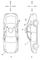
- FIG. 1 shows a vehicle 1 on which a vehicle lighting device 4 according to the present embodiment (hereinafter referred to as a lighting device 4) is mounted.
- FIG. 1A shows a top view of the vehicle 1
- FIG. 1B shows a side view of the vehicle 1.
- the vehicle 1 is an automobile that can travel in the automatic operation mode, and includes a lighting device 4.
- the lighting device 4 includes a lighting unit 42 and a lighting control unit 43 (see FIG. 2), and the lighting unit 42 of the lighting device 4 is disposed on the vehicle body roof of the vehicle 1 (see FIG. 1). Furthermore, the illumination unit 42 irradiates light to the entire periphery (360 degrees) of the illumination unit 42 in the horizontal direction.
- the horizontal direction is a direction including the front-rear direction and the left-right direction.
- the lighting unit 42 can present information indicating the operation mode of the vehicle 1 around the entire vehicle 1 in the horizontal direction toward the outside of the vehicle 1.
- the lighting device 4 can present information related to the driving mode toward pedestrians and other vehicles around the vehicle 1.
- the illumination unit 42 is arranged on the vehicle body roof as an example, but the arrangement position and shape of the illumination unit 42 are not particularly limited.
- the lighting unit 42 may be disposed on the vehicle body side surface of the vehicle 1 or the vehicle body back surface facing the road surface.
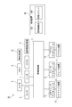
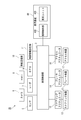
- FIG. 2 shows a block diagram of the vehicle system 2.
- the vehicle system 2 includes a vehicle control unit 3, a lighting device 4, a sensor 5, a camera 6, a radar 7, an HMI (Human Machine Interface) 8, and a GPS (Global Positioning System). 9, a wireless communication unit 10, and a map information storage unit 11.
- the vehicle system 2 includes a steering actuator 12, a steering device 13, a brake actuator 14, a brake device 15, an accelerator actuator 16, and an accelerator device 17.
- the vehicle control unit 3 is configured to control the traveling of the vehicle 1.
- the vehicle control unit 3 is configured by, for example, an electronic control unit (ECU: Electronic Control Unit).
- the electronic control unit includes a microcontroller including a processor and a memory, and other electronic circuits (for example, transistors).
- the processor is, for example, a CPU (Central Processing Unit), an MPU (Micro Processing Unit), and / or a GPU (Graphics Processing Unit).
- the memory includes a ROM (Read Only Memory) that stores various vehicle control programs (for example, an artificial intelligence (AI) program for automatic driving), and a RAM (Random Access Memory) that temporarily stores various vehicle control data. )including.
- the processor is configured to develop a program designated from various vehicle control programs stored in the ROM on the RAM and execute various processes in cooperation with the RAM.
- the illumination device 4 includes the illumination unit 42 and the illumination control unit 43 as described above.
- the illumination unit 42 includes a plurality of light emitting elements such as LEDs (Light Emitting Diodes) and lasers, and is configured to irradiate light toward the outside of the vehicle 1.
- the illumination control unit 43 is configured by an electronic control unit (ECU).
- the electronic control unit is electrically connected to a power source (not shown), and includes a microcontroller including a processor such as a CPU and MPU and a memory such as a ROM and a RAM, and other electronic circuits (for example, a drive circuit such as an LED driver).
- the vehicle control unit 3 and the illumination control unit 43 are provided as separate configurations, but may be configured integrally.
- the illumination control unit 43 and the vehicle control unit 3 may be configured by a single electronic control unit.
- the illumination control unit 43 is configured to change the illumination state (lights on / off, illumination color, emission intensity, emission region or blinking cycle, etc.) of the illumination unit 42 according to the operation mode (described later) of the vehicle 1. Yes.
- the vehicle control unit 3 generates a mode signal indicating the operation mode of the vehicle 1 and transmits the mode signal to the illumination control unit 43.
- the illumination control unit 43 changes the illumination state of the illumination unit 42 based on the received mode signal.
- Sensor 5 includes an acceleration sensor, a speed sensor, a gyro sensor, and the like.
- the sensor 5 is configured to detect the traveling state of the vehicle 1 and output traveling state information to the vehicle control unit 3.
- the sensor 5 may further include a seating sensor that detects whether the driver is sitting in the driver's seat, a face direction sensor that detects the direction of the driver's face, and an external weather sensor that detects an external weather condition.
- the camera 6 is a camera including an image pickup element such as a CCD (Charge-Coupled Device) or a CMOS (Complementary MOS).
- the radar 7 is a millimeter wave radar, a microwave radar, a laser radar, or the like.
- the camera 6 and the radar 7 are configured to detect a surrounding environment (another vehicle, a pedestrian, a road shape, a traffic sign, an obstacle, etc.) of the vehicle 1 and output the surrounding environment information to the vehicle control unit 3. .
- the HMI 8 includes an input unit that receives an input operation from the driver, and an output unit that outputs traveling information and the like to the driver.
- the input unit includes a steering wheel, an accelerator pedal, a brake pedal, an operation mode switching switch for switching the operation mode of the vehicle 1, and the like.
- the output unit is a display that displays various travel information.
- the GPS 9 is configured to acquire the current position information of the vehicle 1 and output the acquired current position information to the vehicle control unit 3.
- the wireless communication unit 10 is configured to receive travel information of other vehicles around the vehicle 1 from other vehicles and to transmit the travel information of the vehicle 1 to other vehicles (inter-vehicle communication).
- the wireless communication unit 10 is configured to receive infrastructure information from infrastructure equipment such as traffic lights and beacon lights, and to transmit travel information of the vehicle 1 to the infrastructure equipment (road-to-vehicle communication).
- the map information storage unit 11 is an external storage device such as a hard disk drive in which map information is stored, and is configured to output the map information to the vehicle control unit 3.
- the vehicle control unit 3 uses at least one of a steering control signal, an accelerator control signal, and a brake control signal based on traveling state information, surrounding environment information, current position information, map information, and the like. Generate one automatically.
- the steering actuator 12 is configured to receive a steering control signal from the vehicle control unit 3 and control the steering device 13 based on the received steering control signal.
- the brake actuator 14 is configured to receive a brake control signal from the vehicle control unit 3 and control the brake device 15 based on the received brake control signal.
- the accelerator actuator 16 is configured to receive an accelerator control signal from the vehicle control unit 3 and to control the accelerator device 17 based on the received accelerator control signal.
- the vehicle system 2 automatically controls the traveling of the vehicle 1.
- the vehicle control unit 3 when the vehicle 1 travels in the manual operation mode, the vehicle control unit 3 generates a steering control signal, an accelerator control signal, and a brake control signal according to the manual operation of the driver with respect to the accelerator pedal, the brake pedal, and the steering wheel.
- the steering control signal, the accelerator control signal, and the brake control signal are generated by the driver's manual operation, so that the traveling of the vehicle 1 is controlled by the driver.
- the operation mode includes an automatic operation mode and a manual operation mode.
- the automatic driving mode includes a fully automatic driving mode, an advanced driving support mode, and a driving support mode.
- the vehicle system 2 In the fully automatic driving mode, the vehicle system 2 automatically performs all traveling control of steering control, brake control, and accelerator control, and the driver is not in a state where the vehicle 1 can be driven.
- the vehicle system 2 In the advanced driving support mode, the vehicle system 2 automatically performs all travel control of steering control, brake control, and accelerator control, and the driver does not drive the vehicle 1 although it is in a state where the vehicle 1 can be driven.
- the vehicle system 2 In the driving support mode, the vehicle system 2 automatically performs some traveling control among the steering control, the brake control, and the accelerator control, and the driver drives the vehicle 1 under the driving support of the vehicle system 2.
- the vehicle system 2 In the manual operation mode, the vehicle system 2 does not automatically perform traveling control, and the driver drives the vehicle 1 without driving assistance from the vehicle system 2.
- the operation mode of the vehicle 1 may be switched by operating an operation mode changeover switch.
- the vehicle control unit 3 changes the driving mode of the vehicle 1 into four driving modes (fully automatic driving mode, advanced driving support mode, driving support mode, manual driving mode) according to the driver's operation on the driving mode changeover switch. ).
- the driving mode of the vehicle 1 is automatically set based on information on a travelable section where the autonomous driving vehicle can travel, a travel prohibition section where travel of the autonomous driving vehicle is prohibited, or information on an external weather condition. It may be switched.
- the vehicle control unit 3 switches the operation mode of the vehicle 1 based on these pieces of information.
- the driving mode of the vehicle 1 may be automatically switched by using a seating sensor, a face direction sensor, or the like. In this case, the vehicle control unit 3 switches the operation mode of the vehicle 1 based on output signals from the seating sensor and the face direction sensor.
- the illumination control unit 43 receives a mode signal indicating the operation mode of the vehicle 1 from the vehicle control unit 3.
- the illumination control unit 43 determines whether or not the received mode signal indicates a fully automatic operation mode (step S10).
- the illumination control unit 43 sets the illumination state of the illumination unit 42 to the illumination state S1 corresponding to the fully automatic operation mode (step S11). .
- the illumination control unit 43 determines whether the mode signal indicates the advanced driving support mode (step S12). When it is determined that the mode signal indicates the advanced driving support mode (YES in step S12), the lighting control unit 43 sets the lighting state of the lighting unit 42 to the lighting state S2 corresponding to the advanced driving support mode (step S13). .
- the lighting control unit 43 determines whether the mode signal indicates the driving support mode (step S14). When it is determined that the mode signal indicates the driving support mode (YES in step S14), the lighting control unit 43 sets the lighting state of the lighting unit 42 to the lighting state S3 corresponding to the driving support mode (step S15).
- the lighting control unit 43 determines that the mode signal does not indicate the driving support mode (NO in step S14)
- the lighting control unit 43 determines that the mode signal indicates the manual driving mode, and changes the lighting state of the lighting unit 42 to the manual driving mode.
- the illumination state S4 corresponding to the mode is set (step S16). In this way, this process ends. Moreover, this process is performed every time the illumination control unit 43 receives a mode signal from the vehicle control unit 3.
- the illumination state of the illumination unit 42 is set to a predetermined illumination state according to the operation mode of the vehicle 1, so that it is directed toward pedestrians and other vehicles around the vehicle 1.
- the illumination device 4 capable of displaying information indicating the operation mode of the vehicle 1 can be provided.
- the lighting state of the lighting unit 42 changes between the lighting states S1 to S4 according to the driving mode of the vehicle 1, the driving mode of the vehicle 1 is completely set for pedestrians and other vehicles around the vehicle 1. It is possible to visually recognize whether the driving mode is the automatic driving mode, the advanced driving support mode, the driving support mode, or the manual driving mode.
- the illumination states S1 to S4 are preferably different illumination states.
- the lighting state of the lighting unit 42 changes from the lighting state S2 to the lighting state S3. Therefore, pedestrians and other vehicles around the vehicle 1 It can be understood that the driving mode of the vehicle 1 has changed from the advanced driving support mode to the driving support mode.
- ⁇ Lighting state change lighting unit 42 turned on / off>
- the illumination control unit 43 turns the illumination unit 42 on and off.
- case 1 the case where the illumination control unit 43 turns on the illumination unit 42 when the operation mode of the vehicle 1 is the fully automatic operation mode (hereinafter referred to as case 1) will be described.
- the illumination control unit 43 turns on the illumination unit 42 in the illumination state S1 shown in FIG. 3, and turns off the illumination unit 42 in the illumination states S2 to S4.
- case 1 pedestrians and other vehicles around the vehicle 1 can visually recognize that the operation mode of the vehicle 1 is the fully automatic operation mode.
- the lighting control unit 43 lights the lighting unit 42 when the driving mode of the vehicle 1 is the fully automatic driving mode or the advanced driving support mode (Case 2) will be described.
- the illumination control unit 43 turns on the illumination unit 42 in the illumination states S1 and S2, and turns off the illumination unit 42 in the illumination states S3 and S4.
- pedestrians and other vehicles around the vehicle 1 can visually recognize that the driving mode of the vehicle 1 is the fully automatic driving mode or the advanced driving support mode.
- the lighting control unit 43 lights the lighting unit 42 when the driving mode of the vehicle 1 is the fully automatic driving mode, the advanced driving support mode, or the driving support mode (Case 3) will be described.
- the illumination control unit 43 turns on the illumination unit 42 in the illumination states S1 to S3 and turns off the illumination unit 42 in the illumination state S4.
- a pedestrian or other vehicle around the vehicle 1 visually recognizes that the driving mode of the vehicle 1 is the fully automatic driving mode, the advanced driving support mode, or the driving support mode (that is, the automatic driving mode). Can do. In other words, other vehicles can visually recognize that the driving mode of the vehicle 1 is the automatic driving mode.
- the following table summarizes the lighting states of the lighting states S1 to S4 in each of the cases 1 to 3.
- the lighting control unit 43 turns on the lighting unit 42 in the lighting state S1 and turns off the lighting unit 42 in the lighting states S2 to S4.
- the lighting unit 42 may be turned off, and the lighting unit 42 may be turned on in the lighting states S2 to S4. Even in this case, pedestrians and other vehicles around the vehicle 1 can visually recognize that the operation mode of the vehicle 1 is the fully automatic operation mode.
- the lighting control unit 43 may turn off the lighting unit 42 in the lighting states S1 and S2 and turn on the lighting unit 42 in the lighting states S3 and S4.
- the illumination control unit 43 may turn off the illumination unit 42 in the illumination states S1 to S3 and turn on the illumination unit 42 in the illumination state S4. Even in this case, the same effect as described above can be obtained.
- the illumination color of the illumination unit 42 is green when the illumination unit 42 is turned on.
- ⁇ Change in lighting state light emitting area of lighting unit 42>
- the illumination control unit 43 changes the light emitting area of the illumination unit 42.
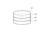
- the lighting unit 42 has three light emitting regions 421 to 423.
- light emitting elements such as LEDs that are turned on and off independently are arranged in the respective light emitting regions 421 to 423.
- the illumination control unit 43 lights the light emitting areas 421 to 423 in the lighting state S1, turns on the light emitting areas 421 and 422 in the lighting state S2, turns on the light emitting area 421 in the lighting state S3, and turns on the lighting state S4.
- the light emitting areas 421 to 423 may be turned off. In this way, the light emission area of the illumination unit 42 differs in each of the illumination states S1 to S4.
- the light emitting area of the lighting unit 42 changes according to the automatic driving mode of the vehicle 1
- information indicating the driving mode of the vehicle 1 toward pedestrians or other vehicles around the vehicle 1 is provided.
- the displayable illumination device 4 can be provided.
- the change in the light emitting area is merely an example. As long as the light emission area of the lighting unit 42 changes according to the automatic driving mode of the vehicle 1, various examples of changes in the light emission area can be applied.
- illumination color of illumination unit 42 ⁇ Change in illumination state: illumination color of illumination unit 42>
- the illumination control unit 43 changes the illumination color of the illumination unit 42 will be described as another example of changing the illumination state of the illumination unit 42.
- a plurality of (for example, three) light emitting elements such as LEDs are arranged in the illumination unit 42, and the emission colors of light emitted from the respective light emitting elements are different.
- the illumination control unit 43 sets the illumination color of the illumination unit 42 to white in the illumination state S1, sets the illumination color of the illumination unit 42 to green in the illumination state S2, and illuminates the illumination unit 42 in the illumination state S3.
- the color may be set to blue, and the illumination color of the illumination unit 42 may be set to red in the illumination state S4 or the illumination unit 42 may be turned off (the illumination color is black).
- the illumination color of the illumination unit 42 is different in each of the illumination states S1 to S4.
- the illumination color of the illumination unit 42 changes according to the driving mode of the vehicle 1, information indicating the driving mode of the vehicle 1 can be displayed toward pedestrians and other vehicles around the vehicle 1.
- the lighting device 4 can be provided.
- the change in illumination color is just an example. As long as the illumination color of the illumination unit 42 changes according to the driving mode of the vehicle 1, various examples of the illumination color change can be applied.
- the illumination control unit 43 may change the blinking cycle of the illumination unit 42 (strictly, the blinking cycle of light emitted from the illumination unit 42). .
- the illumination control unit 43 sets the blinking cycle of the illumination unit 42 to T1 in the illumination state S1, sets the blinking cycle of the illumination unit 42 to T2 in the illumination state S2, and blinks the illumination unit 42 in the illumination state S3.
- the cycle may be set to T3, and the blinking cycle of the illumination unit 42 may be set to T4 in the illumination state S4.
- the lighting control unit 43 may change the light emission intensity of the lighting unit 42.
- the illumination control unit 43 sets the emission intensity of the illumination unit 42 to I1 in the illumination state S1, sets the emission intensity of the illumination unit 42 to I2 in the illumination state S2, and emits light of the illumination unit 42 in the illumination state S3.
- the intensity may be set to I3, and the light emission intensity of the illumination unit 42 may be set to I4 in the illumination state S4.
- the lighting unit 42 has been turned on / off, the light emitting area, the illumination color, the blinking cycle, and the light emission intensity are changed. It is not limited to. As long as the lighting state of the lighting unit 42 can be changed according to the operation mode of the vehicle 1, various changes in the lighting state can be applied. For example, it is also possible to change the illumination state of the illumination unit 42 by combining lighting on / off of the illumination unit 42, light emission region, illumination color, blinking cycle, and emission intensity.
- the lighting control unit 43 predicts the lifetime of the lighting unit 42 based on the current value and voltage value of the lighting control circuit constituting the lighting control unit 43 and the temperature and humidity inside the lighting unit 42. Based on the predicted life of the lighting unit 42, the lighting state (lights on / off, light emitting area, lighting color, blinking cycle, light emission intensity) of the lighting unit may be changed. For example, when it is predicted that the lifetime of the lighting unit 42 is short (for example, when the predicted lifetime is 100 hours or less), the lighting control unit 43 changes the lighting color of the lighting unit 42 to the first lighting color (for example, red). It may be set.
- the first lighting color for example, red
- the lighting control unit 43 changes the illumination color of the lighting unit 42 to the second illumination color (for example , Yellow). Furthermore, when it is predicted that the predicted life of the lighting unit 42 is long (for example, when the predicted life is 500 hours or longer), the lighting control unit 43 sets the lighting color of the lighting unit 42 to the third lighting color (for example, green). May be set.
- the vehicle control unit 3 may predict the life of the illumination unit 42. In this case, the lighting control unit 43 may change the lighting state of the lighting unit 42 based on the received data after receiving data indicating the predicted life of the lighting unit 42 from the vehicle control unit 3.
- a temperature sensor configured to measure the internal temperature of the illumination unit 42 and a humidity sensor configured to measure the internal humidity of the illumination unit 42 may be provided inside the illumination unit 42.
- a life prediction formula indicating a relationship between the usage time t of the light emitting element and the luminance L of the light emitting element may be stored in the memory of the illumination control unit 43.
- the illumination control unit 43 may determine the predicted lifetime of the lighting unit 42 based on the lifetime prediction formula and the current luminance L of the light emitting element.
- the lifetime prediction formula stored in the memory may be acquired via the wireless communication unit 10 from a server arranged on the communication network. In this case, the illumination control unit 43 may periodically acquire a life prediction formula updated from a server arranged on the communication network.
- the lighting control unit 43 is a server After obtaining the lifetime prediction formula based on the indoor temperature of 50 degrees from the above, the predicted lifetime of the lighting unit 42 is determined based on the lifetime prediction formula based on the acquired indoor temperature of 50 degrees and the current luminance L of the light emitting element. May be. Thus, since an appropriate lifetime prediction formula can be acquired via the communication network, the lifetime of the lighting unit 42 can be predicted more accurately.
- the illumination control part 43 changes the illumination state of the illumination unit 42 according to the estimated lifetime of the illumination unit 42, the information regarding the lifetime of the illumination unit 42 can be presented toward the exterior of a vehicle. In this way, a pedestrian or the like existing outside the vehicle can grasp the life of the lighting unit 42 by visually recognizing the lighting state of the lighting unit 42.
- the lighting control unit 43 may change the lighting state (lights on / off, light emitting area, lighting color, blinking cycle, light emission intensity) of the lighting unit 42 based on the current situation of the driver. For example, when one of the plurality of cameras 6 is configured to image the driver, the vehicle control unit 3 acquires the captured image captured by the driver from the camera 6 and then acquires the acquired image. The current situation of the driver may be determined based on the captured image and the face recognition algorithm.
- the vehicle control unit 3 determines that the driver cannot drive the vehicle (for example, when the driver determines that the driver is asleep)
- the vehicle control unit 3 generates a predetermined lighting control signal, and then A predetermined illumination control signal is transmitted to the illumination controller 43.
- the illumination control unit 43 may set the illumination color of the illumination unit 42 to a predetermined illumination color (for example, red) based on the predetermined illumination control signal. In this way, information regarding the current situation of the driver can be presented toward the outside of the vehicle.
- the illumination state of the illumination unit 42 is changed according to the operation mode of the vehicle 1, but a speaker (not shown) is used instead of the illumination unit 42 or in addition to the illumination unit 42.
- the sound output from the speaker may be changed according to the mode.
- the speaker may be installed at a predetermined position of the vehicle so as to output a sound indicating the motion mode of the vehicle 1 toward the outside of the vehicle.
- a speaker control unit (not shown) configured to control the speaker may store data relating to sound indicating the motion mode of the vehicle 1.
- the speaker control unit may store data related to the pitch and magnitude of the sound indicating the motion mode of the vehicle 1, rhythm, voice, melody, and voice guidance.
- the speaker control unit receives a mode signal indicating the operation mode of the vehicle 1 from the vehicle control unit 3 and then outputs a sound to be output to the speaker according to the received mode signal (for example, the pitch and magnitude of the sound, Rhythm, voice, melody, voice guidance). Thereafter, the speaker control unit causes the speaker to output the determined voice guidance.
- the information which shows the driving mode of the vehicle 1 can be shown to the pedestrian who exists outside the vehicle, another vehicle, etc. by using a speaker.
- FIG. 5 shows a vehicle 1A equipped with a vehicle lighting device 4A (hereinafter referred to as a lighting device 4A) according to the present embodiment.
- FIG. 5A shows a top view of the vehicle 1A
- FIG. 5B shows a side view of the vehicle 1A.
- the vehicle 1A is an automobile that can travel in the fully automatic operation mode, and includes an illumination device 4A.
- the illumination device 4A includes an illumination unit 42A and an illumination control unit 43A (see FIG. 6), and the illumination unit 42A of the illumination device 4A is disposed on the vehicle body roof of the vehicle 1A (see FIG. 5). Furthermore, the illumination unit 42A irradiates light to the entire periphery (360 degrees) of the illumination unit 42A in the horizontal direction.
- the horizontal direction is a direction including the front-rear direction and the left-right direction.
- the lighting unit 42A indicates that the vehicle 1A is traveling in the fully automatic driving mode in a state where no occupant is present in the driver's seat all around the vehicle 1A in the horizontal direction (360 degrees) toward the outside of the vehicle 1A. Can be presented.
- the lighting device 4A can present the information to pedestrians and other vehicles around the vehicle 1A.
- the illumination unit 42A is arranged on the vehicle body roof as an example, but the arrangement position and shape of the illumination unit 42A are not particularly limited.
- the lighting unit 42A may be disposed on the vehicle body side surface of the vehicle 1A or the vehicle body back surface facing the road surface.
- FIG. 6 shows a block diagram of the vehicle system 2A.
- the vehicle system 2A has substantially the same configuration as the vehicle system 2 shown in FIG. 2 except for the illumination device 4A.
- the illumination device 4A includes the illumination unit 42A and the illumination control unit 43A as described above.
- the illumination unit 42A includes a plurality of light emitting elements such as LEDs and lasers, and is configured to emit light toward the outside of the vehicle 1A.
- the illumination control unit 43A is configured by an electronic control unit (ECU).
- ECU electronice control unit
- the illumination control unit 43A The state (lights on / off, illumination color, light emission region, blinking cycle, light emission intensity, etc.) is configured to be set to a predetermined illumination state.
- the illumination control unit 43A may be configured to turn on or off the illumination unit 42A.
- the illumination control unit 43A may set the illumination color of the illumination unit 42A to a predetermined illumination color (for example, white, green, blue, etc.). Furthermore, the illumination control unit 43A may set the light emission area of the illumination unit 42A as a predetermined light emission area (for example, half of the volume of the illumination unit 42A is set as the light emission area). Furthermore, the illumination control unit 43A may set the blinking cycle of the illumination unit 42A to a predetermined blinking cycle T. Furthermore, the illumination control unit 43A may set the emission intensity of the illumination unit 42A to a predetermined emission intensity I.
- a predetermined illumination color for example, white, green, blue, etc.
- the illumination control unit 43A may set the light emission area of the illumination unit 42A as a predetermined light emission area (for example, half of the volume of the illumination unit 42A is set as the light emission area).
- the illumination control unit 43A may set the blinking cycle of the illumination unit 42A to a predetermined blinking cycle T.
- the illumination control unit 43A may set
- the vehicle control unit 3 generates a predetermined lighting control signal when it is determined that the operation mode of the vehicle 1A is the fully automatic operation mode and no occupant is present in the driver seat of the vehicle 1A.
- the predetermined illumination control signal is transmitted to the illumination control unit 43A.
- the lighting control unit 43A sets the lighting state of the lighting unit 42A to a predetermined lighting state based on the received predetermined lighting control signal.
- the illumination control unit 43A and the vehicle control unit 3 are provided as separate components, but may be configured integrally. That is, the illumination control unit 43A and the vehicle control unit 3 may be configured by a single electronic control unit.
- the vehicle control unit 3 determines whether or not the operation mode of the vehicle 1A is the fully automatic operation mode (step S20).
- the vehicle control unit 3 determines whether a passenger is present in the driver's seat of the vehicle 1A by using a seating sensor, a human sensor, or the like. It judges using (step S21).
- the vehicle control unit 3 determines that no occupant is present in the driver's seat (YES in step S21), the vehicle control unit 3 generates a lighting signal (an example of a predetermined lighting control signal) and transmits the lighting signal to the lighting control unit 43A. To do. Thereafter, the lighting control unit 43A turns on the lighting unit 42A based on the lighting signal (step S22).
- a lighting signal an example of a predetermined lighting control signal
- step S20 determines that the driving mode of the vehicle 1A is not the fully automatic driving mode (NO in step S20) or determines that an occupant is present in the driver's seat (NO in step S21)
- the vehicle The control unit 3 generates a turn-off signal and transmits the turn-off signal to the illumination control unit 43A.
- the illumination control unit 43A turns off the illumination unit 42A based on the turn-off signal (step S23).
- step S21 may be performed before step S20, and step S20 and step S21 may be performed simultaneously.
- vehicle information information indicating that the vehicle 1A is traveling in the fully automatic driving mode without any passengers in the driver's seat.
- vehicle information can be displayed for pedestrians and other vehicles around the vehicle 1A, and the vehicle system 2A can be provided.
- pedestrians and other vehicles around the vehicle 1A can visually recognize that the vehicle is traveling in the fully automatic driving mode with no occupants in the driver's seat by turning on the lighting unit 42A.
- the lighting device 4A displays the vehicle information to the outside by turning on the lighting unit 42A.
- the vehicle is displayed.
- the information may be displayed outward (in this case, the illumination unit 42A is turned off in step S22, while the illumination unit 42A is turned on in step S23).
- the illuminating device 4A may display the vehicle information to the outside by setting the illumination state (illumination color, light emitting area, blinking cycle, etc.) of the illumination unit 42A to a predetermined illumination state.
- FIG. 8A is a flowchart showing a process of turning on the lighting unit 42A when a call signal is received from a mobile device such as a smartphone or a tablet carried by a pedestrian or the like.
- FIG. 8B is a flowchart showing a process of turning on the lighting unit 42A when an automatic parking instruction signal is received from the mobile device.
- the owner of the vehicle 1A uses the mobile device to call the vehicle 1A at a position distant from the current position of the vehicle 1A to the current position of the user.
- a situation is assumed in which an unmanned driving taxi (a taxi that travels automatically without a passenger) is called to its current location using the device.
- an unmanned driving taxi a taxi that travels automatically without a passenger
- the wireless communication unit 10 receives a call signal from a mobile device via a communication network such as the Internet (step S30).
- the call signal may include current location information of the mobile device.
- the vehicle control unit 3 acquires the call signal from the wireless communication unit 10
- the vehicle control unit 3 activates the vehicle system 2A from the sleep state (step S31).
- the vehicle control unit 3 sets the operation mode of the vehicle 1A to the fully automatic operation mode. In this state, the illumination unit 42A is turned off. Thereafter, the vehicle control unit 3 determines whether an occupant is present in the driver's seat using a seating sensor, a human sensor, or the like (step S32).
- the vehicle control unit 3 When it is determined that no occupant is present in the driver's seat (YES in step S32), the vehicle control unit 3 generates a lighting signal and transmits the lighting signal to the lighting control unit 43A. Thereafter, the lighting control unit 43A turns on the lighting unit 42A based on the lighting signal (step S33). Thereafter, the vehicle 1A starts traveling in the fully automatic operation mode and travels to the current position of the mobile device. On the other hand, when the vehicle control unit 3 determines that an occupant is present in the driver's seat (NO in step S32), the lighting unit 42A remains off.
- the wireless communication unit 10 receives an automatic parking instruction signal from the mobile device via the communication network (step S40).
- the automatic parking instruction signal may include parking location information.
- the vehicle control unit 3 acquires the automatic parking instruction signal from the wireless communication unit 10, the vehicle control unit 3 sets the operation mode of the vehicle 1A to the fully automatic operation mode. In this state, the illumination unit 42A is turned off. Thereafter, the vehicle control unit 3 determines whether an occupant is present in the driver's seat using a seating sensor, a human sensor, or the like (step S41). When it is determined that no occupant is present in the driver's seat (YES in step S41), the vehicle control unit 3 generates a lighting signal and transmits the lighting signal to the lighting control unit 43A.
- the lighting control unit 43A turns on the lighting unit 42A based on the lighting signal (step S42). Thereafter, the vehicle 1A executes automatic parking based on the automatic driving instruction signal (step S43). On the other hand, when the vehicle control unit 3 determines that an occupant is present in the driver's seat (NO in step S41), the lighting unit 42A remains off.
- the lighting device 4A displays the vehicle information to the outside by turning on the lighting unit 42A.
- the lighting state of the lighting unit 42A (lighting color, light emitting area, blinking cycle, etc.)
- the vehicle information may be displayed to the outside by setting to a predetermined lighting state.
- the illumination color of the illumination unit 42A is preferably green.
- the illumination control unit 43A changes the illumination state (lights on / off / light emitting area / illumination color / flashing cycle / light emission intensity) of the illumination unit 42A based on the predicted life of the illumination unit 42A. May be. Furthermore, the illumination control unit 43A may change the illumination state of the illumination unit 42A based on the current situation of the driver. Further, by using a speaker, information indicating that the vehicle 1A is traveling in the fully automatic driving mode without a passenger in the driver's seat is presented to pedestrians or other vehicles existing outside the vehicle 1A. Also good.
- FIG. 9 shows a vehicle 1B equipped with a vehicle lighting device 4B (hereinafter referred to as a lighting device 4B) according to the present embodiment.
- FIG. 9A shows a top view of the vehicle 1B
- FIG. 9B shows a side view of the vehicle 1B.
- the vehicle 1B is an automobile that can travel in the fully automatic operation mode, and includes a lighting device 4B.
- the lighting device 4B includes a lighting unit 42B and a lighting control unit 43B (see FIG. 10), and the lighting unit 42B of the lighting device 4B is disposed on the vehicle body roof of the vehicle 1B (see FIG. 9). Furthermore, the illumination unit 42B irradiates light to the entire periphery (360 degrees) of the illumination unit 42B in the horizontal direction.
- the lighting unit 42B may present information indicating that the vehicle 1B is traveling in the fully automatic driving mode in a state where occupants are present on the entire periphery of the vehicle 1B in the horizontal direction toward the outside of the vehicle 1B. it can.
- the lighting device 4B can present the information to pedestrians and other vehicles around the vehicle 1B.
- the illumination unit 42B is arranged on the vehicle body roof as an example, but the arrangement position and shape of the illumination unit 42B are not particularly limited.
- the lighting unit 42B may be disposed on the vehicle body side surface of the vehicle 1B or the vehicle body back surface facing the road surface.
- FIG. 10 shows a block diagram of the vehicle system 2B.
- the vehicle system 2B has substantially the same configuration as the vehicle system 2 shown in FIG. 2 except for the illumination device 4B.
- the illumination device 4B includes the illumination unit 42B and the illumination control unit 43B as described above.
- the lighting unit 42B includes one or more light emitting elements such as LEDs and lasers, and is configured to emit light toward the outside of the vehicle 1B.
- the illumination control unit 43B is configured by an electronic control unit (ECU).
- ECU electronice control unit
- the illumination state (point) Off, illumination color, light emission area, blinking cycle, light emission intensity, etc.) are set to a predetermined illumination state.
- the illumination control unit 43B may be configured to turn on or off the illumination unit 42B.
- the illumination control unit 43B may set the illumination color of the illumination unit 42B to a predetermined illumination color (for example, white, green, blue, etc.). Furthermore, the illumination control unit 43B may set the light emission area of the illumination unit 42B to a predetermined light emission area (for example, half of the volume of the illumination unit 42B is set as the light emission area). Furthermore, the illumination control unit 43B may set the blinking cycle of the illumination unit 42B to a predetermined blinking cycle T. Furthermore, the illumination control unit 43B may set the emission intensity of the illumination unit 42B to a predetermined emission intensity I.
- a predetermined illumination color for example, white, green, blue, etc.
- the illumination control unit 43B may set the light emission area of the illumination unit 42B to a predetermined light emission area (for example, half of the volume of the illumination unit 42B is set as the light emission area).
- the illumination control unit 43B may set the blinking cycle of the illumination unit 42B to a predetermined blinking cycle T.
- the illumination control unit 43B may set
- the vehicle control unit 3 determines that the operation mode of the vehicle 1B is the fully automatic operation mode and the vehicle 1B has an occupant, the vehicle control unit 3 generates a predetermined illumination control signal, and An illumination control signal is transmitted to the illumination control unit 43B.
- the illumination control unit 43B sets the illumination state of the illumination unit 42B to a predetermined illumination state based on the received predetermined illumination control signal.
- the illumination control part 43B and the vehicle control part 3 are provided as a separate structure, you may be comprised integrally. That is, the illumination control unit 43B and the vehicle control unit 3 may be configured by a single electronic control unit.
- the vehicle control unit 3 determines whether or not the operation mode of the vehicle 1B is the fully automatic operation mode (step S50).
- the vehicle control unit 3 determines whether there is an occupant in the vehicle 1B using a human sensor or the like (step S50). S51).
- the vehicle control unit 3 determines that an occupant is present in the vehicle 1B (YES in step S51)
- the vehicle control unit 3 When the vehicle control unit 3 determines that an occupant is present in the vehicle 1B (YES in step S51), the vehicle control unit 3 generates a lighting signal (an example of a predetermined lighting control signal) and transmits the lighting signal to the lighting control unit 43B. . Thereafter, the lighting control unit 43B turns on the lighting unit 42B based on the lighting signal (step S52).
- step S50 determines that the operation mode of the vehicle 1B is not the fully automatic operation mode (NO in step S50) or determines that no passenger is present in the vehicle (NO in step S51)
- the vehicle The control part 3 produces
- the lighting control unit 43B turns off the lighting unit 42B based on the turn-off signal (step S53).
- step S51 may be performed before step S50, and step S50 and step S51 may be performed simultaneously.
- vehicle information information indicating that the vehicle 1B is traveling in the fully automatic operation mode in the state where the vehicle 1B is present (hereinafter referred to as “vehicle information” as appropriate for convenience of explanation). ) Can be displayed for pedestrians and other vehicles around the vehicle 1B, and the vehicle system 2B can be provided.
- pedestrians and other vehicles around the vehicle 1B can visually recognize that the vehicle 1B is traveling in the fully automatic operation mode with the occupant in the vehicle by turning on the lighting unit 42B.
- the lighting device 4B displays the vehicle information to the outside by turning on the lighting unit 42B.
- the vehicle is displayed.
- Information may be displayed outward (in this case, the illumination unit 42B is turned off in step S52, while the illumination unit 42B is turned on in step S53).
- the illuminating device 4B may display the vehicle information to the outside by setting the illumination state (illumination color, light emitting area, blinking cycle, etc.) of the illumination unit 42B to a predetermined illumination state.
- FIG. 12 is a flowchart showing a process of turning on the lighting unit 42B when the surrounding environment of the vehicle 1B is dark.
- a situation where the surrounding environment of the vehicle 1B is dark a situation where the vehicle 1B is traveling at night, a situation where the vehicle 1B is traveling in a tunnel, or the like can be considered.
- the vehicle control unit 3 determines whether or not the surrounding environment of the vehicle 1B is dark using an illuminance sensor or the like (step S60). If vehicle control unit 3 determines that the surrounding environment of vehicle 1B is dark (YES in step S60), the process proceeds to step S61. On the other hand, when the vehicle control unit 3 determines that the surrounding environment of the vehicle 1B is not dark, the process proceeds to step S64. Steps S61, S62, S63, and S64 correspond to steps S50, S51, S52, and S53 shown in FIG.
- the lighting unit 42B when the surrounding environment of the vehicle 1B is dark, the lighting unit 42B is turned on to display the vehicle information for pedestrians and other vehicles around the vehicle 1B.
- the vehicle 1B since the driver of the vehicle following the vehicle 1B or the oncoming vehicle can visually recognize the vehicle information of the vehicle 1B (particularly, the presence of an occupant in the vehicle), the vehicle 1B is irradiated with glare light such as a high beam. I should hesitate. Therefore, it is possible to prevent the glare light from being radiated to the vehicle 1B by the information indicating that an occupant is present in the vehicle 1B that is running in the fully automatic operation mode.
- the lighting device 4B displays the vehicle information to the outside by turning on the lighting unit 42B.
- the lighting state of the lighting unit 42B (lighting color, light emitting area, blinking cycle, etc.)
- the vehicle information may be displayed to the outside by setting to a predetermined lighting state.
- the lighting control unit 43B changes the lighting state (lights on / off, light emitting area, lighting color, blinking cycle, light emission intensity) of the lighting unit 42B based on the predicted life of the lighting unit 42B. May be. Furthermore, the illumination control unit 43B may change the illumination state of the illumination unit 42B based on the current situation of the driver. In addition, by using the speaker, information indicating that the vehicle 1B is traveling in the fully automatic driving mode in a state where an occupant is present in the vehicle 1B is presented to pedestrians and other vehicles existing outside the vehicle 1B. May be.
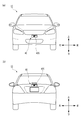
- FIG. 13 shows a vehicle 1C equipped with a display device 4C according to the fourth embodiment.
- FIG. 13A shows a front view of the vehicle 1C
- FIG. 13B shows a rear view of the vehicle 1C.
- the vehicle 1C is an automobile that can travel in the automatic driving mode, and includes a display device 4C.
- the display device 4C is configured to display information indicating that the vehicle 1C is a vehicle that can travel in the automatic driving mode toward the outside of the vehicle 1C, and includes an emblem 42C and an illumination control unit 43C ( (See FIG. 14).
- the emblem 42C of the display device 4C is attached to the front and back of the vehicle body of the vehicle 1C (see FIG. 13).
- the emblem 42C is attached only to a vehicle that can travel in the automatic driving mode, and a pedestrian or other vehicle around the vehicle 1C can see the emblem 42C so that the vehicle 1C is in the automatic driving mode. It can be understood that the vehicle is capable of traveling.
- the emblem 42C includes one or more light emitting elements 420 such as LEDs and lasers, and the light emitting element 420 is configured to irradiate light toward the main body of the emblem 42C.
- FIG. 14 shows a block diagram of the vehicle system 2C.
- the vehicle system 2C has substantially the same configuration as the vehicle system 2 shown in FIG. 2 except for the display device 4C.
- the display device 4C includes the emblem 42C having the light emitting element 420 and the illumination control unit 43C as described above.
- the illumination control unit 43C is configured by an electronic control unit (ECU), and when the operation mode of the vehicle 1C is the automatic operation mode, the light emission state of the light emitting element 420 (lights on / off, illumination color, light emission intensity, light emission region). Or a blinking cycle or the like) is set to a predetermined light emission state.
- ECU electronice control unit
- the illumination control unit 43C may be configured to turn on or turn off the light emitting element 420. Alternatively, the illumination control unit 43C may set the illumination color of the light emitting element 420 to a predetermined illumination color (for example, white, green, blue, etc.). Furthermore, the illumination control unit 43C may set the light emitting area of the light emitting element 420 to a predetermined light emitting area. Furthermore, the illumination control unit 43C may set the blinking cycle of the light emitting element 420 to a predetermined blinking cycle T. Furthermore, the illumination control unit 43C may set the light emission intensity of the light emitting element 420 to a predetermined light emission intensity I.
- a predetermined illumination color for example, white, green, blue, etc.
- the illumination control unit 43C may set the light emitting area of the light emitting element 420 to a predetermined light emitting area.
- the illumination control unit 43C may set the blinking cycle of the light emitting element 420 to a predetermined blinking cycle T.
- the illumination control unit 43C
- the vehicle control unit 3 determines that the operation mode of the vehicle 1 is the automatic operation mode, the vehicle control unit 3 generates a lighting signal and transmits the lighting signal to the illumination control unit 43C.
- the illumination control unit 43C sets the illumination state of the light emitting element 420 to a predetermined illumination state based on the received lighting signal.
- the illumination control unit 43C and the vehicle control unit 3 are provided as separate components, but may be configured integrally. That is, the illumination control unit 43C and the vehicle control unit 3 may be configured by a single electronic control unit.
- the vehicle control unit 3 determines whether the operation mode of the vehicle 1C is the automatic operation mode or the manual operation mode (step S70). When the vehicle control unit 3 determines that the operation mode of the vehicle 1C is the automatic operation mode (YES in step S70), the vehicle control unit 3 generates a lighting signal and transmits the lighting signal to the illumination control unit 43C. Thereafter, the illumination control unit 43C turns on the light emitting element 420 based on the received lighting signal (step S71).
- step S70 when the vehicle control unit 3 determines that the operation mode of the vehicle 1C is the manual operation mode (NO in step S70), the vehicle control unit 3 generates a turn-off signal and transmits the turn-off signal to the illumination control unit 43C. Thereafter, the illumination control unit 43C turns off the light emitting element 420 based on the received turn-off signal (step S72). In this way, a series of processing ends. This process may be repeatedly executed at a predetermined cycle.
- a pedestrian, another vehicle, or the like around the vehicle 1C looks at the illumination state of the light emitting element 420 provided in the emblem 42C, so that the operation mode of the vehicle 1C is automatically driven. It can be understood that the mode.
- a pedestrian, another vehicle, or the like can grasp whether the driving mode of the vehicle 1C is the automatic driving mode or the manual driving mode by seeing the light emitting element 420 being turned on and off.
- the illumination control unit 43C turns on the light emitting element 420 to indicate to the outside that the operation mode of the vehicle 1C is the automatic operation mode.
- the light emitting element 420 may be turned off to indicate to the outside that the driving mode of the vehicle 1C is the automatic driving mode (in this case, the light emitting element 420 is turned off in step S71, while in step S72).
- the light emitting element 420 is turned on).
- the lighting control unit 43C sets the light emitting state of the light emitting element 420 (lighting color, light emitting region, blinking cycle, light emission intensity, etc.) to a predetermined light emitting state, so that the operation mode of the vehicle 1C is the automatic operation mode. May be displayed facing outside.
- 43 C of illumination control parts may set the illumination state of the light emitting element 420 to a predetermined illumination state according to the information which concerns on the automatic driving
- -Information indicating the transition state of the driving mode of the vehicle indicating that the vehicle is running in the fully automatic driving mode in the state where no occupant is present in the driver seat of the vehicle-The vehicle is completely in the state where the occupant is present in the vehicle
- the illumination control unit 43C changes the illumination state (lights on / off, light emission area, illumination color, blinking cycle, light emission intensity) of the light emitting element 420 based on the predicted lifetime of the light emitting element 420. May be. Furthermore, the illumination control unit 43C may change the illumination state of the light emitting element 420 based on the current situation of the driver. Moreover, you may show the information regarding automatic driving
- FIG. 16 shows a vehicle 1D equipped with a display device 4D according to the fifth embodiment.
- FIG. 16A shows a top view of the vehicle 1D
- FIG. 16B shows a left side view of the vehicle 1D.
- the vehicle 1D is an automobile that can travel in the automatic operation mode, and includes a display device 4D.
- the display device 4D is configured to display information indicating that the vehicle 1D is a vehicle that can travel in the automatic driving mode toward the outside of the vehicle 1D, and includes a lighting unit 42D and a lighting control unit 43D. (See FIG. 17). As shown in FIG.
- the illumination unit 42D of the display device 4D is disposed on the vehicle body roof 100D of the vehicle 1D, and emits light to the entire periphery (360 °) of the vehicle 1D in the horizontal direction toward the outside of the vehicle 1D. It is comprised so that it may irradiate.
- the lighting unit 42D is attached only to a vehicle that can travel in the automatic driving mode. A pedestrian or other vehicle around the vehicle 1D can automatically drive the vehicle 1D by looking at the lighting unit 42D. It can be understood that the vehicle can travel in the mode.
- FIG. 17 shows a block diagram of the vehicle system 2D.
- the display device 4D includes the illumination unit 42D and the illumination control unit 43D as described above.
- the illumination unit 42D includes one or more light emitting elements such as LEDs and lasers, and is configured to irradiate light toward the outside of the vehicle 1D.
- the illumination control unit 43D sets the light emission state (lights on / off, illumination color, light emission intensity, light emission region or blinking cycle, etc.) of the lighting unit 42D to a predetermined light emission state. Is configured to do.
- the illumination control unit 43D may be configured to turn on or off the illumination unit 42D.
- the illumination control unit 43D may set the illumination color of the illumination unit 42D to a predetermined illumination color (for example, white, green, blue, etc.).
- the illumination control unit 43D may set the light emission area of the illumination unit 42D to a predetermined light emission area.
- the illumination control unit 43D may set the blinking cycle of the illumination unit 42D to a predetermined blinking cycle T.
- the illumination control unit 43D may set the emission intensity of the illumination unit 42D to a predetermined emission intensity I.
- the vehicle control unit 3 determines whether the operation mode of the vehicle 1D is the automatic operation mode or the manual operation mode (step S80). When the vehicle control unit 3 determines that the operation mode of the vehicle 1D is the automatic operation mode (YES in step S80), the vehicle control unit 3 generates a lighting signal and transmits the lighting signal to the illumination control unit 43D. Thereafter, the lighting control unit 43D turns on the lighting unit 42D based on the received lighting signal (step S81).
- the vehicle control unit 3 determines that the operation mode of the vehicle 1D is the manual operation mode (NO in step S80)
- the vehicle control unit 3 generates a turn-off signal and transmits the turn-off signal to the illumination control unit 43D.
- the illumination control unit 43D turns off the illumination unit 42D based on the received turn-off signal (step S82).
- a pedestrian or other vehicle around the vehicle 1D grasps that the driving mode of the vehicle 1D is the automatic driving mode by looking at the lighting state of the lighting unit 42D. can do.
- a pedestrian, another vehicle, or the like can grasp whether the driving mode of the vehicle 1D is the automatic driving mode or the manual driving mode by seeing the lighting unit 42D being turned on and off.
- the lighting control unit 43D displays the fact that the driving mode of the vehicle 1D is the automatic driving mode by turning on the lighting unit 42D.
- the lighting unit 42D may be turned off to indicate to the outside that the driving mode of the vehicle 1D is the automatic driving mode (in this case, the lighting unit 42D is turned off in step S81, while in step S82) The lighting unit 42D is lit).
- the lighting control unit 43D sets the lighting state (lighting color, light emitting area, blinking cycle, light emission intensity, etc.) of the lighting unit 42D to a predetermined lighting state, so that the driving mode of the vehicle 1D is the automatic driving mode. May be displayed facing outside.
- illumination control part 43D may set the illumination state of illumination unit 42D to a predetermined illumination state according to the information which concerns on the automatic driving
- -Information indicating the transition state of the driving mode of the vehicle indicating that the vehicle is running in the fully automatic driving mode in the state where no occupant is present in the driver seat of the vehicle-The vehicle is completely in the state where the passenger is present in the vehicle
- the lighting control unit 43D changes the lighting state (lights on / off, light emitting area, lighting color, blinking cycle, light emission intensity) of the lighting unit 42D based on the predicted life of the lighting unit 42D. May be. Furthermore, the illumination control unit 43D may change the illumination state of the illumination unit 42D based on the current situation of the driver. Moreover, you may show the information regarding automatic driving
- FIG. 19A shows a front view of the vehicle 1E on which the lighting units 42E1 to E5 are mounted
- FIG. 19B shows a rear view of the vehicle 1E.
- Each of the illumination units 42E1 to E5 includes a light emitting element such as an LED or a laser.
- the illumination units 42E1 to E4 are configured to irradiate light toward the outside of the vehicle 1E, and the illumination unit E5 is configured to irradiate light toward the license plate 70 attached to the vehicle 1E.
- the illumination unit 42E1 is disposed in the left headlamp 20L, and the illumination unit 42E2 is disposed in the right headlamp 20R.
- the lighting unit 42E3 is disposed in the left rear combination lamp 30L, and the lighting unit 42E4 is disposed in the right rear combination lamp 30R.
- the illumination unit 42E5 is disposed in the vicinity of the license plate 70.
- the illumination units 42E1 to E5 can irradiate the entire periphery of the vehicle 1E in the horizontal direction toward the outside of the vehicle 1E.
- the frame surrounding the license plate 70 may emit light.
- the number itself displayed on the license plate 70 may be emitted.
- FIG. 20A shows a left side view of the vehicle 1F on which the lighting unit 42F is mounted
- FIG. 20B shows a front view of the vehicle 1F
- FIG. 20C shows a right side view of the vehicle 1F
- FIG. 20D shows a rear view of the vehicle 1F.
- the illumination unit 42F is disposed on the vehicle body side surface 100F so as to surround the vehicle body side surface 100F of the vehicle 1F over the entire circumferential direction.
- the illumination unit 42F includes a plurality of light emitting elements such as LEDs and lasers provided along the extending direction, and is configured to irradiate light toward the outside of the vehicle 1F.
- the lighting unit 42F is disposed so as to surround the vehicle body side surface 100F, and the plurality of light emitting elements are provided along the extending direction of the lighting unit 42F. Light can be emitted to the entire periphery of the vehicle 1F in the horizontal direction toward the outside.
- the lighting unit 42F is arranged so as to surround the vehicle body side surface 100F continuously (without interruption), but may be arranged so as to surround the vehicle body side surface 100F discontinuously.
- FIG. 21A shows a left side view of a vehicle 1G on which a plurality of (here, six) illumination units 42G are mounted
- FIG. 21B shows a front view of the vehicle 1G
- FIG. c) shows a right side view of the vehicle 1G
- FIG. 21 (d) shows a rear view of the vehicle 1G.
- Each lighting unit 42G is disposed on the back surface 100g of the vehicle 1G facing the road surface R, and includes one or more light emitting elements such as LEDs and lasers. Each lighting unit 42G is configured to irradiate light toward the road surface R around the vehicle 1G.
- Each lighting unit 42G is configured to irradiate the entire periphery of the vehicle 1G in the horizontal direction via the road surface R. That is, the light directly irradiated from the plurality of illumination units 42G is reflected by the road surface R, and the reflected light reflected by the road surface R is irradiated toward the outside of the vehicle 1G around the entire vehicle 1G in the horizontal direction.
- three illumination units 42G are arranged in the front-rear direction on the left side of the vehicle 1G, and the remaining three illumination units 42G are arranged in the front-rear direction on the right side of the vehicle 1G.
- the number and arrangement of 42G are not particularly limited. As long as the lighting unit 42G can irradiate the entire periphery of the vehicle 1G, the number and arrangement of the lighting units 42G can be appropriately changed.
- the plurality of illumination units 42G may be disposed at the end of the back surface 100g (the boundary between the vehicle body side surface and the vehicle body back surface).
- the light emitting element is provided in the lighting unit.
- an optical system composed of a plurality of MEMS (Micro Electro Mechanical Systems) mirrors (not shown) and a plurality of optical fibers optically connecting the light source and the plurality of MEMS mirrors, it is horizontally directed toward the outside of the vehicle. You may implement
- MEMS Micro Electro Mechanical Systems
- the driving mode of the vehicle has been described as including a fully automatic driving mode, an advanced driving support mode, a driving support mode, and a manual driving mode.
- the driving mode of the vehicle includes these four modes. Should not be limited to.
- the driving mode of the vehicle may include at least one of these four modes.
- the driving mode of the vehicle may include only the fully automatic driving mode.
- the vehicular lighting device is configured to always display information indicating the fully automatic operation mode toward the outside of the vehicle.
- the driving mode of the vehicle may include only the manual driving mode.
- the vehicular illumination device is configured to always display information indicating the manual operation mode toward the outside of the vehicle.
- the classification and display form of the driving mode of the vehicle may be changed as appropriate in accordance with laws and regulations concerning automatic driving in each country.
- the definitions of “fully automated driving mode”, “advanced driving support mode”, and “driving support mode” described in the description of the present embodiment are merely examples, and laws or regulations relating to automatic driving in each country or In accordance with the rules, these definitions may be changed as appropriate.
- the lighting control unit may set the lighting state (lights on / off, light emitting area, lighting color, blinking cycle, light emission intensity) of the lighting unit to a predetermined lighting state according to the following information.
- Good ⁇ Information indicating abnormality of vehicle parts (brake, tire, etc.) ⁇ Information indicating whether vehicle is connected to communication network ⁇ Information indicating abnormality of camera, radar, etc. ⁇ Information indicating abnormality of occupant vital signs Information indicating the capacity of the battery installed in the vehicle
Landscapes
- Engineering & Computer Science (AREA)
- Mechanical Engineering (AREA)
- Transportation (AREA)
- Automation & Control Theory (AREA)
- Chemical & Material Sciences (AREA)
- Combustion & Propulsion (AREA)
- Lighting Device Outwards From Vehicle And Optical Signal (AREA)
Abstract
Description
自動運転モードで走行可能な車両の外部に向けて当該車両の運転モードを示す情報を表示するように構成された車両用照明装置であって、
前記車両の外部に向けて光を照射するように構成された照明ユニットと、
前記車両の運転モードに応じて、前記照明ユニットの照明状態を所定の照明状態に設定するように構成された照明制御部と、を備える。
前記照明制御部は、前記車両の運転モードが高度運転支援モードであるときに、前記照明ユニットの照明状態を第2の照明状態に設定し、
前記照明制御部は、前記車両の運転モードが運転支援モードであるときに、前記照明ユニットの照明状態を第3の照明状態に設定し、
前記照明制御部は、前記車両の運転モードが手動運転モードであるときに、前記照明ユニットの照明状態を第4の照明状態に設定してもよい。
前記車両用照明装置は、
前記車両の外部に光を照射するように構成された照明ユニットと、
前記車両の運転モードが完全自動運転モードであって、前記車両の運転席に乗員が存在しないときに、前記照明ユニットの照明状態を所定の照明状態に設定するように構成された照明制御部と、を備える。
前記車両用照明装置は、
前記車両の外部に光を照射するように構成された照明ユニットと、
前記車両の運転モードが完全自動運転モードであって、前記車両に乗員が存在するときに、前記照明ユニットの照明状態を所定の照明状態に設定するように構成された照明制御部と、を備える。
以下、第1実施形態について図面を参照しながら説明する。尚、本実施形態の説明において既に説明された部材と同一の参照番号を有する部材については、説明の便宜上、その説明は省略する。また、本図面に示された各部材の寸法は、説明の便宜上、実際の各部材の寸法とは異なる場合がある。
次に、照明ユニット42の照明状態を変化させる一例として、照明制御部43が照明ユニット42を点消灯させる例について説明する。最初に、車両1の運転モードが完全自動運転モードであるときに照明制御部43が照明ユニット42を点灯させる場合(以下、ケース1という。)について説明する。この場合では、照明制御部43は、図3に示す照明状態S1において照明ユニット42を点灯させると共に、照明状態S2~S4において照明ユニット42を消灯させる。ケース1では、車両1の周囲の歩行者や他車等は、車両1の運転モードが完全自動運転モードであることを視認することができる。

次に、照明ユニット42の照明状態を変化させる他の一例として、照明制御部43が照明ユニット42の発光領域を変化させる例について説明する。図4に示すように、照明ユニット42に3つの発光領域421~423があるとする。本例では、各発光領域421~423には、独立して点消灯するLED等の発光素子(図示せず)が配置されている。
次に、照明ユニット42の照明状態を変化させる他の一例として、照明制御部43が照明ユニット42の照明色を変化させる例について説明する。本例では、照明ユニット42には複数(例えば、3つの)のLED等の発光素子(図示せず)が配置されており、各発光素子から出射される光の発光色が異なる。
さらに、照明ユニット42の照明状態を変化させる他の一例として、照明制御部43が照明ユニット42の点滅周期(厳密には、照明ユニット42から照射される光の点滅周期)を変化させてもよい。このとき、照明制御部43は、照明状態S1において照明ユニット42の点滅周期をT1に設定し、照明状態S2において照明ユニット42の点滅周期をT2に設定し、照明状態S3において照明ユニット42の点滅周期をT3に設定し、照明状態S4において照明ユニット42の点滅周期をT4に設定してもよい。
さらに、照明ユニット42の照明状態を変化させる他の一例として、照明制御部43が照明ユニット42の発光強度を変化させてもよい。このとき、照明制御部43は、照明状態S1において照明ユニット42の発光強度をI1に設定し、照明状態S2において照明ユニット42の発光強度をI2に設定し、照明状態S3において照明ユニット42の発光強度をI3に設定し、照明状態S4において照明ユニット42の発光強度をI4に設定してもよい。
以下、第2実施形態について図5から図8を参照しながら説明する。尚、第1実施形態の説明において既に説明された部材と同一の参照番号を有する部材については、説明の便宜上、その説明は省略する。また、本図面に示された各部材の寸法は、説明の便宜上、実際の各部材の寸法とは異なる場合がある。
以下、第3実施形態について図9から図12を参照しながら説明する。尚、第1及び2実施形態の説明において既に説明された部材と同一の参照番号を有する部材については、説明の便宜上、その説明は省略する。また、本図面に示された各部材の寸法は、説明の便宜上、実際の各部材の寸法とは異なる場合がある。
第4実施形態について図13から図15を参照しながら説明する。第4実施形態に係る車両用表示装置4C(以下、単に「表示装置4C」という。)について以下に説明する。
図13は、第4実施形態に係る表示装置4Cが搭載された車両1Cを示す。図13(a)は、車両1Cの正面図を示し、図13(b)は、車両1Cの背面図を示す。車両1Cは、自動運転モードで走行可能な自動車であって、表示装置4Cを備える。表示装置4Cは、車両1Cの外部に向けて車両1Cが自動運転モードで走行可能な車両であることを示す情報を表示するように構成されており、エンブレム42Cと照明制御部43Cとを備える(図14参照)。表示装置4Cのエンブレム42Cは、車両1Cの車体の正面と背面に取り付けられている(図13参照)。エンブレム42Cは、自動運転モードで走行可能な車両のみに取り付けられるものであって、車両1Cの周囲にいる歩行者や他車等は、当該エンブレム42Cを見ることで、車両1Cが自動運転モードで走行可能な車両であることを把握することができる。エンブレム42Cは、図14に示すように、1以上のLEDやレーザ等の発光素子420を含み、発光素子420は、エンブレム42Cの本体に向けて光を照射するように構成されている。
・車両の運転モードの移行状態を示す情報
・車両の運転席に乗員が存在しない状態で車両が完全自動運転モードにより走行中であることを示す情報
・車両に乗員が存在する状態で車両が完全自動運転モードにより走行中であることを示す情報
・車両の停止を予告する停止予告情報
・車両の自動運転制御が異常状態にあることを示す情報
・完全自動運転モードで走行中の車両の乗車の可否を示す情報
次に、第5実施形態に係る表示装置4Dについて以下に説明する。
図16は、第5実施形態に係る表示装置4Dが搭載された車両1Dを示す。図16(a)は、車両1Dの上面図を示し、図16(b)は、車両1Dの左側面図を示す。車両1Dは、自動運転モードで走行可能な自動車であって、表示装置4Dを備える。表示装置4Dは、車両1Dの外部に向けて車両1Dが自動運転モードで走行可能な車両であることを示す情報を表示するように構成されており、照明ユニット42Dと照明制御部43Dとを備える(図17参照)。図16に示すように、表示装置4Dの照明ユニット42Dは、車両1Dの車体ルーフ100D上に配置されており、車両1Dの外部に向けて水平方向における車両1Dの全周囲(360°)に光を照射するように構成されている。照明ユニット42Dは、自動運転モードで走行可能な車両のみに取り付けられるものであって、車両1Dの周囲にいる歩行者や他車等は、当該照明ユニット42Dを見ることで、車両1Dが自動運転モードで走行可能な車両であることを把握することができる。
・車両の運転モードの移行状態を示す情報
・車両の運転席に乗員が存在しない状態で車両が完全自動運転モードにより走行中であることを示す情報
・車両に乗員が存在する状態で車両が完全自動運転モードにより走行中であることを示す情報
・車両の停止を予告する停止予告情報
・車両の自動運転制御が異常状態にあることを示す情報
・完全自動運転モードで走行中の車両の乗車の可否を示す情報
次に、図19を参照して照明ユニットの第1変形例について説明する。図19(a)は、照明ユニット42E1~E5が搭載された車両1Eの正面図を示し、図19(b)は、車両1Eの背面図を示す。
次に、図20を参照して照明ユニットの第2変形例について説明する。図20(a)は、照明ユニット42Fが搭載された車両1Fの左側面図を示し、図20(b)は、車両1Fの正面図を示し、図20(c)は、車両1Fの右側面図を示し、図20(d)は、車両1Fの背面図を示す。
次に、図21を参照して照明ユニットの第3変形例について説明する。図21(a)は、複数(ここでは、6つ)の照明ユニット42Gが搭載された車両1Gの左側面図を示し、図21(b)は、車両1Gの正面図を示し、図21(c)は、車両1Gの右側面図を示し、図21(d)は、車両1Gの背面図を示す。
・車両の部品(ブレーキやタイヤ等)の異常を示す情報
・車両が通信ネットワークに接続されているかどうかを示す情報
・カメラやレーダ等の異常を示す情報
・乗員のバイタルサインの異常を示す情報
・車両に搭載されたバッテリーの容量を示す情報
Claims (22)
- 自動運転モードで走行可能な車両の外部に向けて当該車両の運転モードを示す情報を表示するように構成された車両用照明装置であって、
前記車両の外部に向けて光を照射するように構成された照明ユニットと、
前記車両の運転モードに応じて、前記照明ユニットの照明状態を所定の照明状態に設定するように構成された照明制御部と、を備えた車両用照明装置。 - 前記照明制御部は、前記車両の運転モードが所定の運転モードであるときに、前記照明ユニットを点灯又は消灯させる、請求項1に記載の車両用照明装置。
- 前記照明制御部は、前記車両の運転モードが完全自動運転モードであるときに、前記照明ユニットを点灯又は消灯させる、請求項2に記載の車両用照明装置。
- 前記照明制御部は、前記車両の運転モードが完全自動運転モード又は高度運転支援モードであるときに、前記照明ユニットを点灯又は消灯させる、請求項2に記載の車両用照明装置。
- 前記照明制御部は、前記車両の運転モードが完全自動運転モード、高度運転支援モード又は運転支援モードであるときに、前記照明ユニットを点灯又は消灯させる、請求項2に記載の車両用照明装置。
- 前記照明制御部は、前記車両の運転モードが完全自動運転モードであるときに、前記照明ユニットの照明状態を第1の照明状態に設定し、
前記照明制御部は、前記車両の運転モードが高度運転支援モードであるときに、前記照明ユニットの照明状態を第2の照明状態に設定し、
前記照明制御部は、前記車両の運転モードが運転支援モードであるときに、前記照明ユニットの照明状態を第3の照明状態に設定し、
前記照明制御部は、前記車両の運転モードが手動運転モードであるときに、前記照明ユニットの照明状態を第4の照明状態に設定する、請求項1に記載の車両用照明装置。 - 前記照明制御部は、前記車両の運転モードに応じて、前記照明ユニットの照明色、発光強度、発光領域又は点滅周期を変化させるように構成されている、請求項1又は6に記載の車両用照明装置。
- 請求項1から7のうちいずれか一項に記載の車両用照明装置と、
前記車両の運転モードを示すモード信号を前記車両用照明装置に送信し、前記車両の走行を制御するように構成された車両制御部と、を備えた車両システム。 - 完全自動運転モードで走行可能な車両の外部に向けて当該車両の運転席に乗員が存在しない状態で当該車両が完全自動運転モードにより走行中であることを示す情報を表示するように構成された車両用照明装置であって、
前記車両の外部に光を照射するように構成された照明ユニットと、
前記車両の運転モードが完全自動運転モードであって、前記車両の運転席に乗員が存在しないときに、前記照明ユニットの照明状態を所定の照明状態に設定するように構成された照明制御部と、を備えた車両用照明装置。 - 前記照明制御部は、前記車両の運転モードが完全自動運転モードであって、前記車両の運転席に乗員が存在しないときに、前記照明ユニットを点灯又は消灯させる、請求項9に記載の車両用照明装置。
- 請求項9に記載の車両用照明装置と、
前記車両の運転モードが完全自動運転モードであって、前記車両の運転席に乗員が存在しないときに、所定の制御信号を前記車両用照明装置に送信するように構成された車両制御部と、を備え、
前記照明制御部は、前記所定の照明制御信号に基づいて前記照明ユニットの照明状態を所定の照明状態に設定するように構成されている、車両システム。 - 完全自動運転モードで走行可能な車両の外部に向けて当該車両に乗員が存在する状態で当該車両が完全自動運転モードにより走行中であることを示す情報を表示するように構成された車両用照明装置であって、
前記車両の外部に光を照射するように構成された照明ユニットと、
前記車両の運転モードが完全自動運転モードであって、前記車両に乗員が存在するときに、前記照明ユニットの照明状態を所定の照明状態に設定するように構成された照明制御部と、を備えた車両用照明装置。 - 前記照明制御部は、前記車両の運転モードが完全自動運転モードであって、前記車両に乗員が存在するときに、前記照明ユニットを点灯又は消灯させる、請求項12に記載の車両用照明装置。
- 請求項12に記載の車両用照明装置と、
前記車両の運転モードが完全自動運転モードであって、前記車両に乗員が存在するときに、所定の制御信号を前記車両用照明装置に送信するように構成された車両制御部と、を備え、
前記照明制御部は、前記所定の照明制御信号に基づいて前記照明ユニットの照明状態を所定の照明状態に設定するように構成されている、車両システム。 - 車両の外部に向けて当該車両が自動運転モードで走行可能な車両であることを示す情報を表示するように構成された車両用表示装置。
- 前記車両の車体に取り付けられたエンブレムを備える、請求項15に記載の車両用表示装置。
- 前記車両の外部に向けて光を照射するように構成された照明ユニットを備える、請求項15に記載の車両用表示装置。
- 前記エンブレムは、発光素子を有しており、
前記車両の運転モードが自動運転モードであるときに、前記発光素子の発光状態を所定の発光状態に設定するように構成された照明制御部をさらに備える、請求項16に記載の車両用表示装置。 - 前記車両の運転モードが自動運転モードであるときに、前記照明ユニットの照明状態を所定の照明状態に設定するように構成された照明制御部をさらに備える、請求項17に記載の車両用表示装置。
- 前記照明制御部は、前記車両の運転モードが自動運転モードであるときに、前記発光素子を点灯又は消灯させる、請求項18に記載の車両用表示装置。
- 前記照明制御部は、前記車両の運転モードが自動運転モードであるときに、前記照明ユニットを点灯又は消灯させる、請求項19に記載の車両用表示装置。
- 請求項8、11及び14のうちいずれか一項に記載の車両システムを備えた、自動運転モードで走行可能な車両。
Priority Applications (4)
| Application Number | Priority Date | Filing Date | Title |
|---|---|---|---|
| US15/771,352 US20180304804A1 (en) | 2015-10-27 | 2016-10-26 | Vehicular illumination device, vehicle system and vehicle |
| EP16859861.3A EP3369621A4 (en) | 2015-10-27 | 2016-10-26 | VEHICLE LIGHTING DEVICE, VEHICLE SYSTEM AND VEHICLE |
| JP2017547838A JP6914843B2 (ja) | 2015-10-27 | 2016-10-26 | 車両用照明装置、車両システム及び車両 |
| CN201680063307.3A CN108349430B (zh) | 2015-10-27 | 2016-10-26 | 车辆用照明装置、车辆系统以及车辆 |
Applications Claiming Priority (8)
| Application Number | Priority Date | Filing Date | Title |
|---|---|---|---|
| JP2015211217 | 2015-10-27 | ||
| JP2015-211216 | 2015-10-27 | ||
| JP2015211215 | 2015-10-27 | ||
| JP2015211216 | 2015-10-27 | ||
| JP2015-211215 | 2015-10-27 | ||
| JP2015-211217 | 2015-10-27 | ||
| JP2015-211214 | 2015-10-27 | ||
| JP2015211214 | 2015-10-27 |
Publications (1)
| Publication Number | Publication Date |
|---|---|
| WO2017073632A1 true WO2017073632A1 (ja) | 2017-05-04 |
Family
ID=58630535
Family Applications (1)
| Application Number | Title | Priority Date | Filing Date |
|---|---|---|---|
| PCT/JP2016/081783 WO2017073632A1 (ja) | 2015-10-27 | 2016-10-26 | 車両用照明装置、車両システム及び車両 |
Country Status (5)
| Country | Link |
|---|---|
| US (1) | US20180304804A1 (ja) |
| EP (1) | EP3369621A4 (ja) |
| JP (1) | JP6914843B2 (ja) |
| CN (1) | CN108349430B (ja) |
| WO (1) | WO2017073632A1 (ja) |
Cited By (10)
| Publication number | Priority date | Publication date | Assignee | Title |
|---|---|---|---|---|
| WO2019026437A1 (ja) * | 2017-08-03 | 2019-02-07 | 株式会社小糸製作所 | 車両用照明システム及び車両 |
| WO2019035433A1 (ja) * | 2017-08-14 | 2019-02-21 | 株式会社小糸製作所 | 自動運転車両 |
| JP2019119289A (ja) * | 2017-12-28 | 2019-07-22 | 株式会社小糸製作所 | 車両用表示システム |
| CN110126719A (zh) * | 2018-02-09 | 2019-08-16 | 株式会社小糸制作所 | 车辆用照明系统及车辆 |
| WO2020080133A1 (ja) * | 2018-10-16 | 2020-04-23 | 株式会社小糸製作所 | 車両用装置 |
| WO2020116239A1 (ja) * | 2018-12-04 | 2020-06-11 | 株式会社小糸製作所 | 赤外線カメラシステム及び車両 |
| WO2020179577A1 (ja) * | 2019-03-01 | 2020-09-10 | 株式会社小糸製作所 | 車両用エンブレムシステム、車両用エンブレムユニット、車両用エンブレム取付ユニット |
| US10960807B2 (en) | 2019-05-09 | 2021-03-30 | Toyota Jidosha Kabushiki Kaisha | Vehicle head light control apparatus |
| WO2022230779A1 (ja) * | 2021-04-27 | 2022-11-03 | 株式会社デンソー | 車両用報知制御装置及び車両用報知制御方法 |
| JP7480801B2 (ja) | 2021-04-27 | 2024-05-10 | 株式会社デンソー | 車両用報知制御装置及び車両用報知制御方法 |
Families Citing this family (13)
| Publication number | Priority date | Publication date | Assignee | Title |
|---|---|---|---|---|
| FR3064224B1 (fr) * | 2017-03-23 | 2021-06-04 | Peugeot Citroen Automobiles Sa | Dispositif de signalisation de phase(s) de conduite d’un vehicule autonome |
| US20190066548A1 (en) * | 2017-08-22 | 2019-02-28 | Ford Global Technologies, Llc | Vehicle emblem assembly |
| JPWO2020080132A1 (ja) * | 2018-10-19 | 2021-09-09 | 株式会社小糸製作所 | 発光装置および車両用灯具の発光装置シリーズ |
| CN113226848A (zh) * | 2018-12-28 | 2021-08-06 | 株式会社小糸制作所 | 车辆用灯具 |
| JP2021049928A (ja) | 2019-09-26 | 2021-04-01 | 株式会社Subaru | 自動運転可能な車両 |
| JP2021049929A (ja) | 2019-09-26 | 2021-04-01 | 株式会社Subaru | 自動運転可能な車両 |
| JP7361555B2 (ja) * | 2019-09-26 | 2023-10-16 | 株式会社Subaru | 自動運転可能な車両 |
| JP7356855B2 (ja) * | 2019-09-26 | 2023-10-05 | 株式会社Subaru | 自動運転可能な車両 |
| JP2021049930A (ja) | 2019-09-26 | 2021-04-01 | 株式会社Subaru | 自動運転可能な車両 |
| JP7356854B2 (ja) | 2019-09-26 | 2023-10-05 | 株式会社Subaru | 自動運転可能な車両 |
| JP7356853B2 (ja) * | 2019-09-26 | 2023-10-05 | 株式会社Subaru | 自動運転可能な車両 |
| KR20220042818A (ko) * | 2020-09-28 | 2022-04-05 | 현대자동차주식회사 | 모터진동 기반 전기차 감속 및 회생제동 조건 시 음색제어 방법 |
| KR20220086374A (ko) * | 2020-12-16 | 2022-06-23 | 현대모비스 주식회사 | 탈착식 주행안내 시스템 및 주행안내 방법 |
Citations (6)
| Publication number | Priority date | Publication date | Assignee | Title |
|---|---|---|---|---|
| JPH08255020A (ja) * | 1995-03-17 | 1996-10-01 | Hitachi Ltd | 自動走行車両 |
| JP2010000949A (ja) * | 2008-06-20 | 2010-01-07 | Toyota Motor Corp | 運転支援装置 |
| JP2013103701A (ja) * | 2011-11-17 | 2013-05-30 | Ichikoh Ind Ltd | 車両用エンブレム |
| JP2014069671A (ja) * | 2012-09-28 | 2014-04-21 | Nissan Motor Co Ltd | ステアリングホイール内表示装置 |
| JP2015071340A (ja) * | 2013-10-02 | 2015-04-16 | 本田技研工業株式会社 | 車両の表示装置および表示方法 |
| JP2015162005A (ja) * | 2014-02-26 | 2015-09-07 | 富士重工業株式会社 | 自動運転システム |
Family Cites Families (16)
| Publication number | Priority date | Publication date | Assignee | Title |
|---|---|---|---|---|
| US7095318B1 (en) * | 2004-09-28 | 2006-08-22 | Solomon Bekhor | Enhanced vehicle advisory system to advise drivers of other vehicles and passengers in the vehicle of actions taken by the driver |
| CN100449443C (zh) * | 2005-07-18 | 2009-01-07 | 李胜强 | 一种汽车自动驾驶系统 |
| EP2304511B1 (en) * | 2008-06-20 | 2013-05-22 | Toyota Jidosha Kabushiki Kaisha | Driving assistance apparatus |
| JP5251810B2 (ja) * | 2009-09-25 | 2013-07-31 | トヨタ自動車株式会社 | 車両用照明装置 |
| DE102009052590A1 (de) * | 2009-11-10 | 2011-05-12 | Valeo Schalter Und Sensoren Gmbh | Vorrichtung und Verfahren zur Überwachung und Signalisierung von Verkehrssituationen und Betriebszuständen in einem Fahrzeug und im Umfeld des Fahrzeugs |
| JP2014009671A (ja) * | 2012-07-03 | 2014-01-20 | Momose Kikai Sekkei Kk | 二液混合器 |
| KR102072429B1 (ko) * | 2013-02-04 | 2020-02-03 | 엘지이노텍 주식회사 | 차량용 조명장치, 방열장치 및 조명장치 |
| US9342074B2 (en) * | 2013-04-05 | 2016-05-17 | Google Inc. | Systems and methods for transitioning control of an autonomous vehicle to a driver |
| JPWO2015056530A1 (ja) * | 2013-10-17 | 2017-03-09 | みこらった株式会社 | 自動運転車、自動運転車の盗難防止システム、自動運転車の盗難防止プログラム、端末制御用プログラム、自動運転車のレンタル方法及び自動運転車のカーシェアリング方法 |
| DE102013018784B4 (de) * | 2013-11-08 | 2016-02-18 | Audi Ag | Fahrzeug mit Beleuchtungsvorrichtung mit einer längsförmigen Beleuchtungseinrichtung |
| KR101901962B1 (ko) * | 2013-11-08 | 2018-11-07 | 한국전자통신연구원 | 내비게이션을 이용한 자율 주행 제어 장치 및 그 방법 |
| US9607534B2 (en) * | 2013-11-21 | 2017-03-28 | Ford Global Technologies, Llc | Illuminating prismatic badge for a vehicle |
| JP6137001B2 (ja) * | 2014-03-14 | 2017-05-31 | 株式会社デンソー | 車載装置 |
| CN104269053A (zh) * | 2014-08-29 | 2015-01-07 | 陈业军 | 一种智能交通系统、方法及智能汽车 |
| CN204203766U (zh) * | 2014-09-18 | 2015-03-11 | 倪国森 | 阵列式全向监控自动驾驶系统 |
| KR101993104B1 (ko) * | 2015-09-30 | 2019-09-30 | 닛산 지도우샤 가부시키가이샤 | 차량 상태 표시 시스템 |
-
2016
- 2016-10-26 JP JP2017547838A patent/JP6914843B2/ja active Active
- 2016-10-26 EP EP16859861.3A patent/EP3369621A4/en not_active Withdrawn
- 2016-10-26 US US15/771,352 patent/US20180304804A1/en not_active Abandoned
- 2016-10-26 WO PCT/JP2016/081783 patent/WO2017073632A1/ja active Application Filing
- 2016-10-26 CN CN201680063307.3A patent/CN108349430B/zh active Active
Patent Citations (6)
| Publication number | Priority date | Publication date | Assignee | Title |
|---|---|---|---|---|
| JPH08255020A (ja) * | 1995-03-17 | 1996-10-01 | Hitachi Ltd | 自動走行車両 |
| JP2010000949A (ja) * | 2008-06-20 | 2010-01-07 | Toyota Motor Corp | 運転支援装置 |
| JP2013103701A (ja) * | 2011-11-17 | 2013-05-30 | Ichikoh Ind Ltd | 車両用エンブレム |
| JP2014069671A (ja) * | 2012-09-28 | 2014-04-21 | Nissan Motor Co Ltd | ステアリングホイール内表示装置 |
| JP2015071340A (ja) * | 2013-10-02 | 2015-04-16 | 本田技研工業株式会社 | 車両の表示装置および表示方法 |
| JP2015162005A (ja) * | 2014-02-26 | 2015-09-07 | 富士重工業株式会社 | 自動運転システム |
Non-Patent Citations (1)
| Title |
|---|
| See also references of EP3369621A4 * |
Cited By (24)
| Publication number | Priority date | Publication date | Assignee | Title |
|---|---|---|---|---|
| EP3663134A4 (en) * | 2017-08-03 | 2021-07-14 | Koito Manufacturing Co., Ltd. | VEHICLE LIGHTING SYSTEM AND VEHICLE |
| CN110944874A (zh) * | 2017-08-03 | 2020-03-31 | 株式会社小糸制作所 | 车辆用照明系统以及车辆 |
| JP7235659B2 (ja) | 2017-08-03 | 2023-03-08 | 株式会社小糸製作所 | 車両用照明システム及び車両 |
| JPWO2019026437A1 (ja) * | 2017-08-03 | 2020-06-11 | 株式会社小糸製作所 | 車両用照明システム及び車両 |
| WO2019026437A1 (ja) * | 2017-08-03 | 2019-02-07 | 株式会社小糸製作所 | 車両用照明システム及び車両 |
| WO2019035433A1 (ja) * | 2017-08-14 | 2019-02-21 | 株式会社小糸製作所 | 自動運転車両 |
| JP2019119289A (ja) * | 2017-12-28 | 2019-07-22 | 株式会社小糸製作所 | 車両用表示システム |
| JP7025926B2 (ja) | 2017-12-28 | 2022-02-25 | 株式会社小糸製作所 | 車両用表示システム |
| US10994658B2 (en) | 2017-12-28 | 2021-05-04 | Koito Manufacturing Co., Ltd. | Vehicle display system |
| CN110126719A (zh) * | 2018-02-09 | 2019-08-16 | 株式会社小糸制作所 | 车辆用照明系统及车辆 |
| CN110126719B (zh) * | 2018-02-09 | 2022-07-22 | 株式会社小糸制作所 | 车辆用照明系统及车辆 |
| JPWO2020080133A1 (ja) * | 2018-10-16 | 2021-09-02 | 株式会社小糸製作所 | 車両用装置 |
| US11511661B2 (en) | 2018-10-16 | 2022-11-29 | Koito Manufacturing Co., Ltd. | Vehicular apparatus |
| WO2020080133A1 (ja) * | 2018-10-16 | 2020-04-23 | 株式会社小糸製作所 | 車両用装置 |
| JP7345494B2 (ja) | 2018-10-16 | 2023-09-15 | 株式会社小糸製作所 | 車両用装置 |
| JPWO2020116239A1 (ja) * | 2018-12-04 | 2021-11-04 | 株式会社小糸製作所 | 赤外線カメラシステム及び車両 |
| WO2020116239A1 (ja) * | 2018-12-04 | 2020-06-11 | 株式会社小糸製作所 | 赤外線カメラシステム及び車両 |
| JP7382344B2 (ja) | 2018-12-04 | 2023-11-16 | 株式会社小糸製作所 | 赤外線カメラシステム及び車両 |
| JPWO2020179577A1 (ja) * | 2019-03-01 | 2021-12-23 | 株式会社小糸製作所 | 車両用エンブレムシステム、車両用エンブレムユニット、車両用エンブレム取付ユニット |
| WO2020179577A1 (ja) * | 2019-03-01 | 2020-09-10 | 株式会社小糸製作所 | 車両用エンブレムシステム、車両用エンブレムユニット、車両用エンブレム取付ユニット |
| JP7389789B2 (ja) | 2019-03-01 | 2023-11-30 | 株式会社小糸製作所 | 車両用エンブレムシステム、車両用エンブレムユニット、車両用エンブレム取付ユニット |
| US10960807B2 (en) | 2019-05-09 | 2021-03-30 | Toyota Jidosha Kabushiki Kaisha | Vehicle head light control apparatus |
| WO2022230779A1 (ja) * | 2021-04-27 | 2022-11-03 | 株式会社デンソー | 車両用報知制御装置及び車両用報知制御方法 |
| JP7480801B2 (ja) | 2021-04-27 | 2024-05-10 | 株式会社デンソー | 車両用報知制御装置及び車両用報知制御方法 |
Also Published As
| Publication number | Publication date |
|---|---|
| JP6914843B2 (ja) | 2021-08-04 |
| CN108349430A (zh) | 2018-07-31 |
| EP3369621A1 (en) | 2018-09-05 |
| US20180304804A1 (en) | 2018-10-25 |
| CN108349430B (zh) | 2021-06-22 |
| EP3369621A4 (en) | 2019-06-26 |
| JPWO2017073632A1 (ja) | 2018-08-09 |
Similar Documents
| Publication | Publication Date | Title |
|---|---|---|
| WO2017073632A1 (ja) | 車両用照明装置、車両システム及び車両 | |
| JP6910953B2 (ja) | 車両用照明装置 | |
| CN108349429B (zh) | 车辆用照明装置、车辆系统及车辆 | |
| CN109641552B (zh) | 车用照明系统、车辆系统和车辆 | |
| JP6761426B2 (ja) | 車両用照明装置、車両システム及び車両 | |
| JP7204674B2 (ja) | 車両用照明システム、車両、車車間通信システム及び車両システム | |
| CN110154881B (zh) | 车辆用照明系统及车辆 | |
| CN109969072B (zh) | 车辆用照明系统及车辆 | |
| CN110126719B (zh) | 车辆用照明系统及车辆 | |
| JP7043256B2 (ja) | 車両用照明システム及び車両 | |
| CN108367708B (zh) | 车辆用照明装置、车辆及照明控制系统 | |
| JP6980553B2 (ja) | 車両用照明システム及び車両 |
Legal Events
| Date | Code | Title | Description |
|---|---|---|---|
| 121 | Ep: the epo has been informed by wipo that ep was designated in this application |
Ref document number: 16859861 Country of ref document: EP Kind code of ref document: A1 |
|
| ENP | Entry into the national phase |
Ref document number: 2017547838 Country of ref document: JP Kind code of ref document: A |
|
| WWE | Wipo information: entry into national phase |
Ref document number: 15771352 Country of ref document: US |
|
| NENP | Non-entry into the national phase |
Ref country code: DE |
|
| WWE | Wipo information: entry into national phase |
Ref document number: 2016859861 Country of ref document: EP |