WO2017073092A1 - Machine électrique tournante - Google Patents
Machine électrique tournante Download PDFInfo
- Publication number
- WO2017073092A1 WO2017073092A1 PCT/JP2016/055896 JP2016055896W WO2017073092A1 WO 2017073092 A1 WO2017073092 A1 WO 2017073092A1 JP 2016055896 W JP2016055896 W JP 2016055896W WO 2017073092 A1 WO2017073092 A1 WO 2017073092A1
- Authority
- WO
- WIPO (PCT)
- Prior art keywords
- coil
- coil portion
- electrical angle
- phase difference
- angle phase
- Prior art date
Links
Images


Classifications
-
- H—ELECTRICITY
- H02—GENERATION; CONVERSION OR DISTRIBUTION OF ELECTRIC POWER
- H02K—DYNAMO-ELECTRIC MACHINES
- H02K7/00—Arrangements for handling mechanical energy structurally associated with dynamo-electric machines, e.g. structural association with mechanical driving motors or auxiliary dynamo-electric machines
- H02K7/10—Structural association with clutches, brakes, gears, pulleys or mechanical starters
- H02K7/116—Structural association with clutches, brakes, gears, pulleys or mechanical starters with gears
-
- H—ELECTRICITY
- H02—GENERATION; CONVERSION OR DISTRIBUTION OF ELECTRIC POWER
- H02K—DYNAMO-ELECTRIC MACHINES
- H02K3/00—Details of windings
- H02K3/04—Windings characterised by the conductor shape, form or construction, e.g. with bar conductors
- H02K3/28—Layout of windings or of connections between windings
-
- B—PERFORMING OPERATIONS; TRANSPORTING
- B62—LAND VEHICLES FOR TRAVELLING OTHERWISE THAN ON RAILS
- B62D—MOTOR VEHICLES; TRAILERS
- B62D5/00—Power-assisted or power-driven steering
- B62D5/04—Power-assisted or power-driven steering electrical, e.g. using an electric servo-motor connected to, or forming part of, the steering gear
- B62D5/0421—Electric motor acting on or near steering gear
- B62D5/0424—Electric motor acting on or near steering gear the axes of motor and final driven element of steering gear, e.g. rack, being parallel
-
- H—ELECTRICITY
- H02—GENERATION; CONVERSION OR DISTRIBUTION OF ELECTRIC POWER
- H02K—DYNAMO-ELECTRIC MACHINES
- H02K1/00—Details of the magnetic circuit
- H02K1/06—Details of the magnetic circuit characterised by the shape, form or construction
- H02K1/12—Stationary parts of the magnetic circuit
- H02K1/14—Stator cores with salient poles
- H02K1/146—Stator cores with salient poles consisting of a generally annular yoke with salient poles
-
- H—ELECTRICITY
- H02—GENERATION; CONVERSION OR DISTRIBUTION OF ELECTRIC POWER
- H02K—DYNAMO-ELECTRIC MACHINES
- H02K11/00—Structural association of dynamo-electric machines with electric components or with devices for shielding, monitoring or protection
- H02K11/30—Structural association with control circuits or drive circuits
- H02K11/33—Drive circuits, e.g. power electronics
-
- H—ELECTRICITY
- H02—GENERATION; CONVERSION OR DISTRIBUTION OF ELECTRIC POWER
- H02K—DYNAMO-ELECTRIC MACHINES
- H02K21/00—Synchronous motors having permanent magnets; Synchronous generators having permanent magnets
- H02K21/12—Synchronous motors having permanent magnets; Synchronous generators having permanent magnets with stationary armatures and rotating magnets
- H02K21/14—Synchronous motors having permanent magnets; Synchronous generators having permanent magnets with stationary armatures and rotating magnets with magnets rotating within the armatures
- H02K21/16—Synchronous motors having permanent magnets; Synchronous generators having permanent magnets with stationary armatures and rotating magnets with magnets rotating within the armatures having annular armature cores with salient poles
-
- H—ELECTRICITY
- H02—GENERATION; CONVERSION OR DISTRIBUTION OF ELECTRIC POWER
- H02K—DYNAMO-ELECTRIC MACHINES
- H02K29/00—Motors or generators having non-mechanical commutating devices, e.g. discharge tubes or semiconductor devices
- H02K29/03—Motors or generators having non-mechanical commutating devices, e.g. discharge tubes or semiconductor devices with a magnetic circuit specially adapted for avoiding torque ripples or self-starting problems
-
- H—ELECTRICITY
- H02—GENERATION; CONVERSION OR DISTRIBUTION OF ELECTRIC POWER
- H02K—DYNAMO-ELECTRIC MACHINES
- H02K3/00—Details of windings
- H02K3/04—Windings characterised by the conductor shape, form or construction, e.g. with bar conductors
- H02K3/18—Windings for salient poles
-
- H—ELECTRICITY
- H02—GENERATION; CONVERSION OR DISTRIBUTION OF ELECTRIC POWER
- H02K—DYNAMO-ELECTRIC MACHINES
- H02K5/00—Casings; Enclosures; Supports
- H02K5/04—Casings or enclosures characterised by the shape, form or construction thereof
- H02K5/22—Auxiliary parts of casings not covered by groups H02K5/06-H02K5/20, e.g. shaped to form connection boxes or terminal boxes
- H02K5/225—Terminal boxes or connection arrangements
-
- H—ELECTRICITY
- H02—GENERATION; CONVERSION OR DISTRIBUTION OF ELECTRIC POWER
- H02K—DYNAMO-ELECTRIC MACHINES
- H02K1/00—Details of the magnetic circuit
- H02K1/06—Details of the magnetic circuit characterised by the shape, form or construction
- H02K1/22—Rotating parts of the magnetic circuit
- H02K1/27—Rotor cores with permanent magnets
- H02K1/2706—Inner rotors
- H02K1/272—Inner rotors the magnetisation axis of the magnets being perpendicular to the rotor axis
- H02K1/274—Inner rotors the magnetisation axis of the magnets being perpendicular to the rotor axis the rotor consisting of two or more circumferentially positioned magnets
- H02K1/2753—Inner rotors the magnetisation axis of the magnets being perpendicular to the rotor axis the rotor consisting of two or more circumferentially positioned magnets the rotor consisting of magnets or groups of magnets arranged with alternating polarity
- H02K1/276—Magnets embedded in the magnetic core, e.g. interior permanent magnets [IPM]
- H02K1/2766—Magnets embedded in the magnetic core, e.g. interior permanent magnets [IPM] having a flux concentration effect
- H02K1/2773—Magnets embedded in the magnetic core, e.g. interior permanent magnets [IPM] having a flux concentration effect consisting of tangentially magnetized radial magnets
-
- H—ELECTRICITY
- H02—GENERATION; CONVERSION OR DISTRIBUTION OF ELECTRIC POWER
- H02K—DYNAMO-ELECTRIC MACHINES
- H02K1/00—Details of the magnetic circuit
- H02K1/06—Details of the magnetic circuit characterised by the shape, form or construction
- H02K1/22—Rotating parts of the magnetic circuit
- H02K1/27—Rotor cores with permanent magnets
- H02K1/2706—Inner rotors
- H02K1/272—Inner rotors the magnetisation axis of the magnets being perpendicular to the rotor axis
- H02K1/274—Inner rotors the magnetisation axis of the magnets being perpendicular to the rotor axis the rotor consisting of two or more circumferentially positioned magnets
- H02K1/2753—Inner rotors the magnetisation axis of the magnets being perpendicular to the rotor axis the rotor consisting of two or more circumferentially positioned magnets the rotor consisting of magnets or groups of magnets arranged with alternating polarity
- H02K1/278—Surface mounted magnets; Inset magnets
- H02K1/2781—Magnets shaped to vary the mechanical air gap between the magnets and the stator
-
- H—ELECTRICITY
- H02—GENERATION; CONVERSION OR DISTRIBUTION OF ELECTRIC POWER
- H02K—DYNAMO-ELECTRIC MACHINES
- H02K2213/00—Specific aspects, not otherwise provided for and not covered by codes H02K2201/00 - H02K2211/00
- H02K2213/03—Machines characterised by numerical values, ranges, mathematical expressions or similar information
Definitions
- the number of field poles of the rotor is 12n ⁇ 2n (n is a natural number), and the number of slots is 12n.
- An electric motor characterized in that the number of field poles is 18n ⁇ 2n (n is a natural number) and the number of slots is 18n is disclosed, and the motor is reduced in vibration and noise.
- the number of turns of the conducting wire of the coil section is such that the electrical angle phase difference is ⁇ 1 , ⁇ m is different from the number of turns of the conducting wire of the coil portion, and the electrical angle phase difference is the number of turns of the conducting wire of the coil portion adjacent to both sides in the circumferential direction of the stator core of the coil portion of the ⁇ k
- the torque generated by the electric motor 7 is a thrust that moves a rack shaft (not shown) in the housing 10 in the direction of arrow X through a gear box 9 in which a belt (not shown) and a ball screw (not shown) are built.
- a rack shaft (not shown) in the housing 10 in the direction of arrow X
- a gear box 9 in which a belt (not shown) and a ball screw (not shown) are built.
- the tie rod 11 moves and the tire can be steered to turn the vehicle.
- the driver is assisted by the torque of the electric motor 7 and can turn the vehicle with a small steering force.
- the rack boot 12 is provided so that foreign matter does not enter the apparatus.
- FIG. 14 is a longitudinal sectional view showing the electric motor as the reference example.
- the difference from the electric motor of the first embodiment shown in FIG. 3 is that the number of turns and the wire diameter of the conductor 21 are different, and the stator 22
- the structure, that is, the arrangement of the armature winding 38 and each coil portion which is a constituent element thereof is the same as that in FIG.
- FIG. 15 is a diagram showing a method of manufacturing the stator core 20 of the electric motor shown in FIG.
- the stator iron core 20 has tips of adjacent teeth 34 connected to each other, an inner core 57 that includes the teeth 34 and does not include the core back 33, and an outer core 56 that includes the core back 33 and does not include the teeth 34. It is manufactured by press-fitting an inner core 57 into an outer core 56.
- the teeth 34 of the inner core 57 before press-fitting are in a state where the core back 33 is not present, and the coil portion can be inserted from the radially outer side. Then, after inserting a coil part in the inner core 57 with which the insulator 39 was mounted
- the number of turns of the conductive wire 21 of each coil portion of all the teeth 34 is equal.
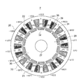
- broken lines that bisect the slots 35 symmetrically in the circumferential direction of the stator 22 are shown in the slots 35, and the coil portions in the slots 35 are shown with respect to the broken lines shown in the slots 35.
- the arrangement of the conductive wires 21 is symmetric about the teeth 34.
- the coil portions of the respective phases correspond to the numbers 1 to 12 of the teeth 34, -U21, + U22, + V11, -V12, -W21, + W22, + U11, -U12, They are arranged in the order of -V21, + V22, + W11, -W12. Note that “+” and “ ⁇ ” indicate the winding polarity of the coil portion, and “+” and “ ⁇ ” have opposite winding polarities.
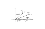
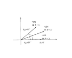
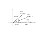
- FIG. 17A is a vector diagram showing the electrical angle phases of the coil portions + U21, ⁇ U22, + U23 connected in series in the U-phase second armature winding portion 37 (see FIGS. 4 and 5) of the first embodiment.
- the vector length indicates the strength of the magnetomotive force generated by the coil portion wound around each tooth 34
- the vector angle indicates the electrical angle phase of the coil portion wound around each tooth 34. Is shown. Since the magnetomotive force of the coil portion is proportional to the product of the number of turns and the magnitude of the current, the length of the vector in the figure is proportional to the number of turns.
- the magnetomotive force vector generated in the coil part in the second armature winding part 37 of the U phase of FIG. 14 shown in the first reference example, in which the number of turns of all the coil parts is equal, is shown in FIG. 17B.
- the magnetomotive force generated by the U phase is represented by the length of the composite vector.
- the magnetomotive forces generated by the coil portions + U21, -U22, + U23 are equal. Therefore, compared with the case where the number of turns of the conducting wires 21 of all the coil portions is equal, in the first embodiment in which the vector whose electrical angle phase is located at the center is large, the combined vector length increases, Magnetic force can be increased. Thereby, the magnetic flux density between the magnetic space
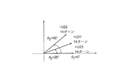
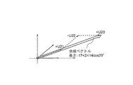
- 18B shows a case where the sum of the numbers of turns of the conductors 21 of all the coil portions wound around each tooth 34 is equal to that of the first embodiment shown in FIG. 18A and all the coil portions have the same number of turns.
- the electric angle phases of the coil portions + U21, -U22, + U23 in the second U-phase winding portion U2 of the second armature winding portion 37 are shown in a vector diagram.
- the sum of the number of turns of the conductive wires 21 of all the coil portions wound around each tooth 34 is referred to as the total number of turns. If the length of the vector is represented by the number of turns, the magnetomotive force of the first embodiment is 17 + 2 ⁇ 14 cos 20 ° by obtaining the length of the combined vector as shown in FIG.
- FIG. 21 shows the mechanical angle phase when the coil portions of the teeth 34 of numbers 4, 8, and 18 are connected in series as a first example in which the connection methods of the U-phase coil portions are different.
- Connection diagrams of the armature winding 38 at this time are shown in FIGS.
- FIG. 22 shows the case of ⁇ connection
- FIG. 23 shows the case of Y connection.
- a series coil section group is formed in which the coil sections of -U13, + U21, and -U22 are connected in series.
- FIG. 24 shows a vector diagram of the electrical angle phase of each coil part of the U-phase series coil part group in the armature winding shown in FIGS. 22 and 23. As shown in the figure, the magnetomotive force generated is the same as that of FIG.
- the coil part + U21 is a multi-winding coil part or a small winding coil part rather than the coil parts -U22 and + U23 has been described.
- the coil part -U22 and the coil part + U23 are multi-turn coils or less than the coil part + U21.
- a wound coil may be used. Since the total number of turns can be specified more finely, the torque of the electric motor 7 can be specified more finely, and the degree of freedom in torque design can be improved.
- the in-phase coil part -U22 and the coil part + U23 are adjacent to each other.
- the resistance can be reduced, the amount of heat generated at the location where the same phase is adjacent can be reduced, and the concentration of heat generation can be suppressed.
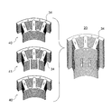
- the insulator inserted into 57 and wound around the teeth B later.
- the coil portion on one side protrudes from the broken line at the center of the slot 35.
- the wire diameter of the coil part wound around the teeth B having the multi-winding coil part is compared with the wire diameters of other in-phase coil parts connected in series with each coil part. Big.
- the coil portion wound around the tooth 34 of the number 1 and the coil portion connected in series to the coil V11 is the coil portion + V12 wound around the tooth 34 of the number 5 and the coil wound around the tooth 34 of the number 6
- the wire diameter of the coil portion -V11 is larger than that of the coil portions + V12 and -V13.
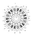
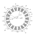
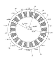
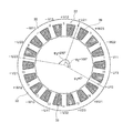
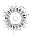
- FIG. 29 is a front sectional view of the electric motor 7 showing a configuration in which the number of turns of the conducting wire 21 of the coil portion wound around each of the teeth 34 of numbers 1, 3, 5, 7, 9, 11, 13, 15, 17 is increased.
- FIG. 29 coil portions having different numbers of turns are arranged in all the slots 35 as compared with the first embodiment shown in FIG. The space factor has been improved.
- the arrangement of the number of turns that is, the distribution of magnetomotive force is not 180 ° rotationally symmetric. Therefore, the configuration shown in the figure is called a magnetomotive force asymmetric configuration.
- the motor 7 having 14 field poles, teeth 34, and 18 slots 35 has an electrical angle phase of a coil part constituting each series coil part group as shown in FIGS. 17A and 18A.
- the arrangement is such that three magnetomotive force vectors are arranged with a phase difference of 20 °.
- the magnetomotive force distribution is 180 ° and rotationally symmetric, so that a maximum of two sets of three phases can be formed during one rotation 360 ° of the electric motor 7. Therefore, by setting the number of parallel circuits to 1 or 2, the number of coils constituting the in-phase series coil section group can be 6 or 3.
- the electric motor 7 of this embodiment is a so-called concentrated winding in which the coil portion is intensively wound around the teeth 34, and has the effect that the coil end is small, the size is small, the copper loss is small, the heat generation is low, and the efficiency is high. It is done. Since the number of (18 ⁇ 4) y field poles (18 is a natural number) and the number of teeth 34 and slots 35 are 18y, the number of field poles is (3 ⁇ 1) y and the number of teeth 34 or slots 35. The torque can be improved as compared with the case of 3y.
- 33 is a table showing the turn ratio when the number of turns of the coil portions of teeth A and B is different.
- the combination of the number of turns was selected such that the sum of the numbers of turns of all the coil portions wound around the stator 22, that is, the total number of turns becomes equal.
- the total number of turns is 216.
- the total number of turns is 216.
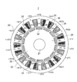
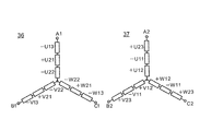
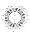
- FIG. FIG. 36 is a front sectional view showing an electric motor 7 according to the third embodiment of the present invention.
- the electric motor 7 of this embodiment in addition to increasing the circumferential width of the tooth B having the multi-winding coil portion so that W B > W A , the tooth B is wound around the tooth B as compared with that of FIG.
- the circumferential width W S2 ′ of the slot 35 in which the coil portion is accommodated is increased, and the width W S1 ′ of the other slots 35 is decreased.
- the other configuration is the same as that of the electric motor 7 of the first embodiment shown in FIG.
Landscapes
- Engineering & Computer Science (AREA)
- Power Engineering (AREA)
- Chemical & Material Sciences (AREA)
- Combustion & Propulsion (AREA)
- Transportation (AREA)
- Mechanical Engineering (AREA)
- Microelectronics & Electronic Packaging (AREA)
- Windings For Motors And Generators (AREA)
Abstract
Priority Applications (4)
| Application Number | Priority Date | Filing Date | Title |
|---|---|---|---|
| EP16859329.1A EP3370327A4 (fr) | 2015-10-28 | 2016-02-26 | Machine électrique tournante |
| US15/759,845 US10833549B2 (en) | 2015-10-28 | 2016-02-26 | Rotary electric machine |
| CN201680061835.5A CN108141090B (zh) | 2015-10-28 | 2016-02-26 | 旋转电机 |
| JP2017547636A JP6415746B2 (ja) | 2015-10-28 | 2016-02-26 | 回転電機 |
Applications Claiming Priority (2)
| Application Number | Priority Date | Filing Date | Title |
|---|---|---|---|
| JP2015211874 | 2015-10-28 | ||
| JP2015-211874 | 2015-10-28 |
Publications (1)
| Publication Number | Publication Date |
|---|---|
| WO2017073092A1 true WO2017073092A1 (fr) | 2017-05-04 |
Family
ID=58631522
Family Applications (1)
| Application Number | Title | Priority Date | Filing Date |
|---|---|---|---|
| PCT/JP2016/055896 WO2017073092A1 (fr) | 2015-10-28 | 2016-02-26 | Machine électrique tournante |
Country Status (5)
| Country | Link |
|---|---|
| US (1) | US10833549B2 (fr) |
| EP (1) | EP3370327A4 (fr) |
| JP (1) | JP6415746B2 (fr) |
| CN (1) | CN108141090B (fr) |
| WO (1) | WO2017073092A1 (fr) |
Cited By (7)
| Publication number | Priority date | Publication date | Assignee | Title |
|---|---|---|---|---|
| US10404124B2 (en) | 2015-10-28 | 2019-09-03 | Mitsubishi Electric Corporation | Rotary electric machine |
| WO2021053797A1 (fr) * | 2019-09-19 | 2021-03-25 | 三菱電機株式会社 | Machine tournante électrique et ventilateur de plafond |
| WO2021060102A1 (fr) * | 2019-09-23 | 2021-04-01 | 株式会社デンソートリム | Machine électrique rotative et stator pour une machine électrique rotative |
| WO2021193462A1 (fr) * | 2020-03-25 | 2021-09-30 | ファナック株式会社 | Moteur |
| JP2021164304A (ja) * | 2020-03-31 | 2021-10-11 | 日本電産株式会社 | モータ |
| WO2022009620A1 (fr) * | 2020-07-06 | 2022-01-13 | 株式会社デンソー | Machine dynamo-électrique |
| JP7272793B2 (ja) | 2015-11-05 | 2023-05-12 | エルジー イノテック カンパニー リミテッド | バスバー、モーター、およびこれを含む動力伝達システム |
Families Citing this family (13)
| Publication number | Priority date | Publication date | Assignee | Title |
|---|---|---|---|---|
| US20190068044A1 (en) * | 2010-01-25 | 2019-02-28 | Svetozar B. Petrovich | In Evolution of Gravity Fields |
| CN108886313B (zh) * | 2016-03-29 | 2020-10-09 | 三菱电机株式会社 | 电动机 |
| JP6844614B2 (ja) * | 2016-03-30 | 2021-03-17 | 日本電産株式会社 | モータ |
| US11387764B2 (en) * | 2018-07-12 | 2022-07-12 | Zunum Aero, Inc. | Multi-inverter system for electric machine |
| JP7408628B2 (ja) * | 2018-08-07 | 2024-01-05 | タウ モーターズ,インコーポレイテッド | 電動機 |
| JP7293702B2 (ja) * | 2019-02-08 | 2023-06-20 | 株式会社デンソー | 回転電機 |
| JP6912508B2 (ja) * | 2019-03-19 | 2021-08-04 | ファナック株式会社 | 固定子および電動機 |
| JP7103299B2 (ja) * | 2019-04-22 | 2022-07-20 | 株式会社デンソー | 回転電機 |
| GB2586989B (en) * | 2019-09-11 | 2022-07-27 | Rolls Royce Plc | Electric Machines |
| JP7227938B2 (ja) * | 2020-05-15 | 2023-02-22 | 株式会社デンソー | 回転電機 |
| JP2023535312A (ja) * | 2020-07-20 | 2023-08-17 | ムーグ インコーポレーテッド | 耐故障性冗長電気モータ |
| JP6991298B1 (ja) * | 2020-10-21 | 2022-01-12 | 三菱電機株式会社 | 電流検出装置 |
| CN116633059B (zh) * | 2023-05-15 | 2024-05-14 | 浙江大学 | 一种电机成型绕组结构及其加工方法 |
Citations (3)
| Publication number | Priority date | Publication date | Assignee | Title |
|---|---|---|---|---|
| JP2011223676A (ja) * | 2010-04-06 | 2011-11-04 | Mitsubishi Electric Corp | 永久磁石式電動機 |
| WO2013080374A1 (fr) * | 2011-12-02 | 2013-06-06 | 三菱電機株式会社 | Moteur à enroulement concentré du type à aimant permanent |
| JP2014068497A (ja) * | 2012-09-27 | 2014-04-17 | Hitachi Automotive Systems Ltd | 回転電機およびそれを用いた電動パワーステアリング装置 |
Family Cites Families (12)
| Publication number | Priority date | Publication date | Assignee | Title |
|---|---|---|---|---|
| US2711008A (en) * | 1950-10-26 | 1955-06-21 | Beresford James & Son Ltd | Manufacture of stators for electric motors |
| US4403401A (en) * | 1978-09-15 | 1983-09-13 | General Electric Company | Method of making a dynamoelectric machine stator having concentric amorphous metal laminations |
| JP3604577B2 (ja) | 1999-02-26 | 2004-12-22 | 三菱電機株式会社 | 直流モータ |
| US20090230805A1 (en) * | 2005-09-07 | 2009-09-17 | Hirotatsu Ikeno | Motor for electric power steering apparatus |
| JP2009213257A (ja) * | 2008-03-04 | 2009-09-17 | Hitachi Ltd | 回転電機 |
| JP5228582B2 (ja) | 2008-04-04 | 2013-07-03 | 三菱電機株式会社 | 永久磁石型回転電機およびそれを用いた電動パワーステアリング装置 |
| DE102009036034B4 (de) * | 2009-08-04 | 2011-07-07 | FEAAM GmbH, 85579 | Elektrische Maschine |
| DE102011078157A1 (de) | 2011-06-28 | 2013-01-03 | Robert Bosch Gmbh | Elektrische Maschine |
| JP2014158396A (ja) | 2013-02-18 | 2014-08-28 | Mitsubishi Electric Corp | 同期電動機の固定子 |
| KR102124042B1 (ko) | 2013-02-18 | 2020-06-18 | 삼성디스플레이 주식회사 | 기상 증착 장치, 이를 이용한 증착 방법 및 유기 발광 표시 장치 제조 방법 |
| CN104283350A (zh) * | 2013-07-02 | 2015-01-14 | 丹佛斯(天津)有限公司 | 定子、电机和压缩机 |
| JP5677530B2 (ja) * | 2013-08-07 | 2015-02-25 | 東芝産業機器システム株式会社 | 回転電機の固定子巻線、回転電機の固定子、回転電機の固定子の製造方法、及び回転電機の固定子の製造に用いる治具 |
-
2016
- 2016-02-26 EP EP16859329.1A patent/EP3370327A4/fr active Pending
- 2016-02-26 WO PCT/JP2016/055896 patent/WO2017073092A1/fr active Application Filing
- 2016-02-26 CN CN201680061835.5A patent/CN108141090B/zh active Active
- 2016-02-26 JP JP2017547636A patent/JP6415746B2/ja active Active
- 2016-02-26 US US15/759,845 patent/US10833549B2/en active Active
Patent Citations (3)
| Publication number | Priority date | Publication date | Assignee | Title |
|---|---|---|---|---|
| JP2011223676A (ja) * | 2010-04-06 | 2011-11-04 | Mitsubishi Electric Corp | 永久磁石式電動機 |
| WO2013080374A1 (fr) * | 2011-12-02 | 2013-06-06 | 三菱電機株式会社 | Moteur à enroulement concentré du type à aimant permanent |
| JP2014068497A (ja) * | 2012-09-27 | 2014-04-17 | Hitachi Automotive Systems Ltd | 回転電機およびそれを用いた電動パワーステアリング装置 |
Non-Patent Citations (1)
| Title |
|---|
| See also references of EP3370327A4 * |
Cited By (11)
| Publication number | Priority date | Publication date | Assignee | Title |
|---|---|---|---|---|
| US10404124B2 (en) | 2015-10-28 | 2019-09-03 | Mitsubishi Electric Corporation | Rotary electric machine |
| JP7272793B2 (ja) | 2015-11-05 | 2023-05-12 | エルジー イノテック カンパニー リミテッド | バスバー、モーター、およびこれを含む動力伝達システム |
| WO2021053797A1 (fr) * | 2019-09-19 | 2021-03-25 | 三菱電機株式会社 | Machine tournante électrique et ventilateur de plafond |
| JPWO2021053797A1 (fr) * | 2019-09-19 | 2021-03-25 | ||
| JP7170891B2 (ja) | 2019-09-19 | 2022-11-14 | 三菱電機株式会社 | 回転電機及び天井扇風機 |
| WO2021060102A1 (fr) * | 2019-09-23 | 2021-04-01 | 株式会社デンソートリム | Machine électrique rotative et stator pour une machine électrique rotative |
| JPWO2021060102A1 (ja) * | 2019-09-23 | 2021-10-21 | 株式会社デンソートリム | 回転電機及び回転電機用ステータ |
| WO2021193462A1 (fr) * | 2020-03-25 | 2021-09-30 | ファナック株式会社 | Moteur |
| JP2021164304A (ja) * | 2020-03-31 | 2021-10-11 | 日本電産株式会社 | モータ |
| WO2022009620A1 (fr) * | 2020-07-06 | 2022-01-13 | 株式会社デンソー | Machine dynamo-électrique |
| JP7512720B2 (ja) | 2020-07-06 | 2024-07-09 | 株式会社デンソー | 回転電機 |
Also Published As
| Publication number | Publication date |
|---|---|
| EP3370327A1 (fr) | 2018-09-05 |
| US10833549B2 (en) | 2020-11-10 |
| EP3370327A4 (fr) | 2018-11-21 |
| US20180248433A1 (en) | 2018-08-30 |
| JP6415746B2 (ja) | 2018-10-31 |
| JPWO2017073092A1 (ja) | 2018-02-22 |
| CN108141090B (zh) | 2019-10-18 |
| CN108141090A (zh) | 2018-06-08 |
Similar Documents
| Publication | Publication Date | Title |
|---|---|---|
| JP6415746B2 (ja) | 回転電機 | |
| JP5726329B2 (ja) | 永久磁石型集中巻モータ | |
| US10404124B2 (en) | Rotary electric machine | |
| US9800100B2 (en) | Permanent magnet motor and driving apparatus-integrated permanent magnet motor | |
| JP6091619B2 (ja) | 永久磁石型モータ、及び電動パワーステアリング装置 | |
| US9564779B2 (en) | Permanent magnet motor | |
| US9627936B2 (en) | Permanent magnet motor | |
| JP6636184B2 (ja) | 電動駆動装置および電動パワーステアリング装置 | |
| US20180115202A1 (en) | Rotary electric machine and electric power steering apparatus | |
| WO2016067695A1 (fr) | Machine électrique tournante et dispositif de direction assistée électrique utilisant une machine électrique tournante | |
| WO2016166796A1 (fr) | Dispositif d'entraînement électrique | |
| JP5989154B2 (ja) | 永久磁石型モータ | |
| JP6188639B2 (ja) | 電動機 | |
| JP5905176B1 (ja) | 回転電機および当該回転電機を用いた電動パワーステアリング装置 | |
| JP5072734B2 (ja) | 永久磁石型回転電機およびパワーステアリング装置 | |
| JPWO2013054439A1 (ja) | 永久磁石型モータ |
Legal Events
| Date | Code | Title | Description |
|---|---|---|---|
| 121 | Ep: the epo has been informed by wipo that ep was designated in this application |
Ref document number: 16859329 Country of ref document: EP Kind code of ref document: A1 |
|
| ENP | Entry into the national phase |
Ref document number: 2017547636 Country of ref document: JP Kind code of ref document: A |
|
| WWE | Wipo information: entry into national phase |
Ref document number: 15759845 Country of ref document: US |
|
| NENP | Non-entry into the national phase |
Ref country code: DE |
|
| WWE | Wipo information: entry into national phase |
Ref document number: 2016859329 Country of ref document: EP |