WO2017068994A1 - 車両用スタビライザと、スタビライザの目玉部の加工装置と、目玉部の加工方法 - Google Patents
車両用スタビライザと、スタビライザの目玉部の加工装置と、目玉部の加工方法 Download PDFInfo
- Publication number
- WO2017068994A1 WO2017068994A1 PCT/JP2016/079860 JP2016079860W WO2017068994A1 WO 2017068994 A1 WO2017068994 A1 WO 2017068994A1 JP 2016079860 W JP2016079860 W JP 2016079860W WO 2017068994 A1 WO2017068994 A1 WO 2017068994A1
- Authority
- WO
- WIPO (PCT)
- Prior art keywords
- eyeball
- length
- hole
- trim
- stabilizer
- Prior art date
Links
Images


Classifications
-
- B—PERFORMING OPERATIONS; TRANSPORTING
- B60—VEHICLES IN GENERAL
- B60G—VEHICLE SUSPENSION ARRANGEMENTS
- B60G21/00—Interconnection systems for two or more resiliently-suspended wheels, e.g. for stabilising a vehicle body with respect to acceleration, deceleration or centrifugal forces
- B60G21/02—Interconnection systems for two or more resiliently-suspended wheels, e.g. for stabilising a vehicle body with respect to acceleration, deceleration or centrifugal forces permanently interconnected
- B60G21/04—Interconnection systems for two or more resiliently-suspended wheels, e.g. for stabilising a vehicle body with respect to acceleration, deceleration or centrifugal forces permanently interconnected mechanically
- B60G21/05—Interconnection systems for two or more resiliently-suspended wheels, e.g. for stabilising a vehicle body with respect to acceleration, deceleration or centrifugal forces permanently interconnected mechanically between wheels on the same axle but on different sides of the vehicle, i.e. the left and right wheel suspensions being interconnected
- B60G21/055—Stabiliser bars
-
- B—PERFORMING OPERATIONS; TRANSPORTING
- B21—MECHANICAL METAL-WORKING WITHOUT ESSENTIALLY REMOVING MATERIAL; PUNCHING METAL
- B21D—WORKING OR PROCESSING OF SHEET METAL OR METAL TUBES, RODS OR PROFILES WITHOUT ESSENTIALLY REMOVING MATERIAL; PUNCHING METAL
- B21D53/00—Making other particular articles
- B21D53/88—Making other particular articles other parts for vehicles, e.g. cowlings, mudguards
-
- B—PERFORMING OPERATIONS; TRANSPORTING
- B21—MECHANICAL METAL-WORKING WITHOUT ESSENTIALLY REMOVING MATERIAL; PUNCHING METAL
- B21D—WORKING OR PROCESSING OF SHEET METAL OR METAL TUBES, RODS OR PROFILES WITHOUT ESSENTIALLY REMOVING MATERIAL; PUNCHING METAL
- B21D28/00—Shaping by press-cutting; Perforating
- B21D28/02—Punching blanks or articles with or without obtaining scrap; Notching
-
- B—PERFORMING OPERATIONS; TRANSPORTING
- B21—MECHANICAL METAL-WORKING WITHOUT ESSENTIALLY REMOVING MATERIAL; PUNCHING METAL
- B21D—WORKING OR PROCESSING OF SHEET METAL OR METAL TUBES, RODS OR PROFILES WITHOUT ESSENTIALLY REMOVING MATERIAL; PUNCHING METAL
- B21D28/00—Shaping by press-cutting; Perforating
- B21D28/24—Perforating, i.e. punching holes
-
- B—PERFORMING OPERATIONS; TRANSPORTING
- B21—MECHANICAL METAL-WORKING WITHOUT ESSENTIALLY REMOVING MATERIAL; PUNCHING METAL
- B21D—WORKING OR PROCESSING OF SHEET METAL OR METAL TUBES, RODS OR PROFILES WITHOUT ESSENTIALLY REMOVING MATERIAL; PUNCHING METAL
- B21D45/00—Ejecting or stripping-off devices arranged in machines or tools dealt with in this subclass
- B21D45/003—Ejecting or stripping-off devices arranged in machines or tools dealt with in this subclass in punching machines or punching tools
- B21D45/006—Stripping-off devices
-
- B—PERFORMING OPERATIONS; TRANSPORTING
- B21—MECHANICAL METAL-WORKING WITHOUT ESSENTIALLY REMOVING MATERIAL; PUNCHING METAL
- B21J—FORGING; HAMMERING; PRESSING METAL; RIVETING; FORGE FURNACES
- B21J5/00—Methods for forging, hammering, or pressing; Special equipment or accessories therefor
- B21J5/02—Die forging; Trimming by making use of special dies ; Punching during forging
-
- B—PERFORMING OPERATIONS; TRANSPORTING
- B21—MECHANICAL METAL-WORKING WITHOUT ESSENTIALLY REMOVING MATERIAL; PUNCHING METAL
- B21J—FORGING; HAMMERING; PRESSING METAL; RIVETING; FORGE FURNACES
- B21J5/00—Methods for forging, hammering, or pressing; Special equipment or accessories therefor
- B21J5/06—Methods for forging, hammering, or pressing; Special equipment or accessories therefor for performing particular operations
- B21J5/10—Piercing billets
-
- B—PERFORMING OPERATIONS; TRANSPORTING
- B21—MECHANICAL METAL-WORKING WITHOUT ESSENTIALLY REMOVING MATERIAL; PUNCHING METAL
- B21J—FORGING; HAMMERING; PRESSING METAL; RIVETING; FORGE FURNACES
- B21J9/00—Forging presses
- B21J9/02—Special design or construction
- B21J9/04—Piercing presses
-
- B—PERFORMING OPERATIONS; TRANSPORTING
- B21—MECHANICAL METAL-WORKING WITHOUT ESSENTIALLY REMOVING MATERIAL; PUNCHING METAL
- B21J—FORGING; HAMMERING; PRESSING METAL; RIVETING; FORGE FURNACES
- B21J9/00—Forging presses
- B21J9/10—Drives for forging presses
- B21J9/12—Drives for forging presses operated by hydraulic or liquid pressure
-
- B—PERFORMING OPERATIONS; TRANSPORTING
- B21—MECHANICAL METAL-WORKING WITHOUT ESSENTIALLY REMOVING MATERIAL; PUNCHING METAL
- B21K—MAKING FORGED OR PRESSED METAL PRODUCTS, e.g. HORSE-SHOES, RIVETS, BOLTS OR WHEELS
- B21K21/00—Making hollow articles not covered by a single preceding sub-group
- B21K21/12—Shaping end portions of hollow articles
-
- B—PERFORMING OPERATIONS; TRANSPORTING
- B60—VEHICLES IN GENERAL
- B60G—VEHICLE SUSPENSION ARRANGEMENTS
- B60G21/00—Interconnection systems for two or more resiliently-suspended wheels, e.g. for stabilising a vehicle body with respect to acceleration, deceleration or centrifugal forces
- B60G21/005—Interconnection systems for two or more resiliently-suspended wheels, e.g. for stabilising a vehicle body with respect to acceleration, deceleration or centrifugal forces transversally
-
- B—PERFORMING OPERATIONS; TRANSPORTING
- B60—VEHICLES IN GENERAL
- B60G—VEHICLE SUSPENSION ARRANGEMENTS
- B60G21/00—Interconnection systems for two or more resiliently-suspended wheels, e.g. for stabilising a vehicle body with respect to acceleration, deceleration or centrifugal forces
- B60G21/02—Interconnection systems for two or more resiliently-suspended wheels, e.g. for stabilising a vehicle body with respect to acceleration, deceleration or centrifugal forces permanently interconnected
- B60G21/026—Interconnection systems for two or more resiliently-suspended wheels, e.g. for stabilising a vehicle body with respect to acceleration, deceleration or centrifugal forces permanently interconnected transversally
-
- B—PERFORMING OPERATIONS; TRANSPORTING
- B21—MECHANICAL METAL-WORKING WITHOUT ESSENTIALLY REMOVING MATERIAL; PUNCHING METAL
- B21J—FORGING; HAMMERING; PRESSING METAL; RIVETING; FORGE FURNACES
- B21J5/00—Methods for forging, hammering, or pressing; Special equipment or accessories therefor
- B21J5/02—Die forging; Trimming by making use of special dies ; Punching during forging
- B21J5/022—Open die forging
-
- B—PERFORMING OPERATIONS; TRANSPORTING
- B21—MECHANICAL METAL-WORKING WITHOUT ESSENTIALLY REMOVING MATERIAL; PUNCHING METAL
- B21J—FORGING; HAMMERING; PRESSING METAL; RIVETING; FORGE FURNACES
- B21J5/00—Methods for forging, hammering, or pressing; Special equipment or accessories therefor
- B21J5/02—Die forging; Trimming by making use of special dies ; Punching during forging
- B21J5/027—Trimming
-
- B—PERFORMING OPERATIONS; TRANSPORTING
- B21—MECHANICAL METAL-WORKING WITHOUT ESSENTIALLY REMOVING MATERIAL; PUNCHING METAL
- B21K—MAKING FORGED OR PRESSED METAL PRODUCTS, e.g. HORSE-SHOES, RIVETS, BOLTS OR WHEELS
- B21K21/00—Making hollow articles not covered by a single preceding sub-group
- B21K21/12—Shaping end portions of hollow articles
- B21K21/14—Shaping end portions of hollow articles closed or substantially-closed ends, e.g. cartridge bottoms
-
- B—PERFORMING OPERATIONS; TRANSPORTING
- B60—VEHICLES IN GENERAL
- B60G—VEHICLE SUSPENSION ARRANGEMENTS
- B60G2206/00—Indexing codes related to the manufacturing of suspensions: constructional features, the materials used, procedures or tools
- B60G2206/01—Constructional features of suspension elements, e.g. arms, dampers, springs
- B60G2206/017—Constructional features of suspension elements, e.g. arms, dampers, springs forming an eye for the bushing
-
- B—PERFORMING OPERATIONS; TRANSPORTING
- B60—VEHICLES IN GENERAL
- B60G—VEHICLE SUSPENSION ARRANGEMENTS
- B60G2206/00—Indexing codes related to the manufacturing of suspensions: constructional features, the materials used, procedures or tools
- B60G2206/01—Constructional features of suspension elements, e.g. arms, dampers, springs
- B60G2206/40—Constructional features of dampers and/or springs
- B60G2206/42—Springs
- B60G2206/427—Stabiliser bars or tubes
-
- B—PERFORMING OPERATIONS; TRANSPORTING
- B60—VEHICLES IN GENERAL
- B60G—VEHICLE SUSPENSION ARRANGEMENTS
- B60G2206/00—Indexing codes related to the manufacturing of suspensions: constructional features, the materials used, procedures or tools
- B60G2206/01—Constructional features of suspension elements, e.g. arms, dampers, springs
- B60G2206/70—Materials used in suspensions
- B60G2206/72—Steel
- B60G2206/724—Wires, bars or the like
-
- B—PERFORMING OPERATIONS; TRANSPORTING
- B60—VEHICLES IN GENERAL
- B60G—VEHICLE SUSPENSION ARRANGEMENTS
- B60G2206/00—Indexing codes related to the manufacturing of suspensions: constructional features, the materials used, procedures or tools
- B60G2206/01—Constructional features of suspension elements, e.g. arms, dampers, springs
- B60G2206/80—Manufacturing procedures
- B60G2206/81—Shaping
- B60G2206/8102—Shaping by stamping
- B60G2206/81022—Shaping by stamping by forging
-
- B—PERFORMING OPERATIONS; TRANSPORTING
- B60—VEHICLES IN GENERAL
- B60G—VEHICLE SUSPENSION ARRANGEMENTS
- B60G2206/00—Indexing codes related to the manufacturing of suspensions: constructional features, the materials used, procedures or tools
- B60G2206/01—Constructional features of suspension elements, e.g. arms, dampers, springs
- B60G2206/80—Manufacturing procedures
- B60G2206/81—Shaping
- B60G2206/8103—Shaping by folding or bending
-
- B—PERFORMING OPERATIONS; TRANSPORTING
- B60—VEHICLES IN GENERAL
- B60G—VEHICLE SUSPENSION ARRANGEMENTS
- B60G2206/00—Indexing codes related to the manufacturing of suspensions: constructional features, the materials used, procedures or tools
- B60G2206/01—Constructional features of suspension elements, e.g. arms, dampers, springs
- B60G2206/80—Manufacturing procedures
- B60G2206/81—Shaping
- B60G2206/811—Shaping by cutting
-
- B—PERFORMING OPERATIONS; TRANSPORTING
- B60—VEHICLES IN GENERAL
- B60G—VEHICLE SUSPENSION ARRANGEMENTS
- B60G2206/00—Indexing codes related to the manufacturing of suspensions: constructional features, the materials used, procedures or tools
- B60G2206/01—Constructional features of suspension elements, e.g. arms, dampers, springs
- B60G2206/80—Manufacturing procedures
- B60G2206/83—Punching
Definitions
- the present invention relates to a vehicle stabilizer disposed in a suspension mechanism of a vehicle such as an automobile, a stabilizer processing apparatus for the stabilizer, and a method of processing the center part.
- the stabilizer arranged in the suspension mechanism part of the vehicle is made of a steel pipe or a solid rod-shaped steel material, and a pair of torsion parts (twisting parts) extending in the width direction of the vehicle and a pair of ends connected to both ends of the torsion part via bending parts And an arm portion (arm portion).
- An eyeball portion is formed at the tip of each arm portion.
- the torsion portion of the stabilizer is supported on the vehicle body via a support portion having a rubber bush.
- the eyeball is connected to a suspension arm or the like via a connecting member such as a stabilizer link.
- the stabilizer assembled to the suspension mechanism portion can increase the roll rigidity of the vehicle by the arm portion, the bending portion, and the torsion portion functioning as springs with respect to the rolling behavior of the vehicle body.
- the stabilizer described in Patent Literature 1 and Patent Literature 2 has a pair of eyeballs formed by crushing both ends of a steel pipe by upsetting.
- Each eyeball has a flat fastening surface.
- a through hole is formed in each fastening surface.
- a connecting member such as a stabilizer link is inserted into the through hole.
- the eyeball portion is connected to a suspension mechanism member such as a suspension arm via the connection member.
- a connecting member such as a stabilizer link is fixed to a fastening surface of the center part by a screw member such as a nut.
- a screw member such as a nut.
- an object of the present invention is to provide a vehicle stabilizer including an eyeball portion having a highly accurate fastening surface, an eyeball portion processing apparatus, and an eyeball portion processing method.
- One embodiment is a vehicle stabilizer made of a rod-shaped steel material (a steel pipe or a solid steel bar), and is connected to a torsion portion extending in the width direction of the vehicle via bent portions from both ends of the torsion portion. It has a pair of arm parts and a pair of eyeballs.
- the eyeball parts are respectively a first plane and a second plane parallel to each other, a trim part located at the tip of each eyeball part and having a tip surface perpendicular to the first plane and the second plane, A through hole having an inner surface perpendicular to the first plane and the second plane and opening in the first plane and the second plane; and a part of the first plane formed around the opening of the through hole.
- a flat annular reference surface, a distal end side bending portion, and a hole side bending portion is formed at a first corner portion where the first plane and the distal end surface intersect with each other outside the annular reference surface, and has a first length from the first plane toward the distal end surface.
- the thickness decreases over time.
- the hole-side curved portion is formed on the entire inner periphery of the opening at a second corner portion where the first plane and the inner surface of the through hole intersect inside the annular reference surface, and from the first plane to the inner surface The thickness decreases toward a length shorter than the first length and is curved with a curvature larger than that of the distal-end bending portion.
- the distance from the outer periphery of the annular reference surface to the tip surface may be smaller than the distance from the outer periphery of the annular reference surface to the opening.
- the hole-side curved portion has a second length-trimmed curved surface formed at a position near the trim portion, and a third length anti-trimmed-curved surface formed on the side far from the trim portion. The third length may be smaller than the second length.
- the curvature of the anti-trim-side curved surface may be larger than the curvature of the trim-side curved surface.
- the annular reference surface (where the tip side curved portion formed when the trim portion is cut and the hole side curved portion formed when the through hole is punched exist around the through hole of the eyeball portion ( It is possible to suppress the influence on the fastening surface), and to provide a vehicle stabilizer having a highly accurate fastening surface.
- FIG. 1 is a perspective view showing a part of a vehicle and a stabilizer.
- FIG. 2 is a plan view of the stabilizer according to the first embodiment.
- FIG. 3 is a plan view of the center portion of the stabilizer shown in FIG.
- FIG. 4 is a cross-sectional view of the eyeball along the line F4-F4 in FIG.
- FIG. 5 is a plan view in which an annular reference surface is hatched in the center part of a stabilizer according to the second embodiment.
- FIG. 6 is a cross-sectional view showing a state in which the eyeball portion is placed on the lower mold in a part of the eyeball portion processing apparatus.
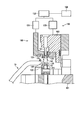
- FIG. 7 is a cross-sectional view of the processing apparatus in a state where the hydraulic drive stripper is lowered.
- FIG. 1 is a perspective view showing a part of a vehicle and a stabilizer.
- FIG. 2 is a plan view of the stabilizer according to the first embodiment.
- FIG. 3 is a plan view
- FIG. 8 is a cross-sectional view showing a state where the upper die and the punch are lowered by the processing apparatus.
- FIG. 9 is a cross-sectional view of the processing apparatus in a state where the upper mold is raised.
- FIG. 10 is a cross-sectional view showing a state where the punch is raised by the processing apparatus.
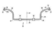
- FIG. 1 shows a part of a vehicle 11 provided with a vehicle stabilizer (hereinafter simply referred to as a stabilizer) 10.
- the stabilizer 10 forms a part of a suspension mechanism that is disposed below the vehicle body 12 of the vehicle 11.
- FIG. 2 is a plan view showing an example of the stabilizer 10.
- the stabilizer 10 is made of a rod-shaped steel material (for example, a steel pipe), and includes a stabilizer body 20 and a pair of eyeballs 21 and 22 formed integrally at both ends of the stabilizer body 20.
- the stabilizer 10 has the eyeballs 21 and 22 formed by flattening the end of the steel pipe by plastic working such as forging. For this reason, the stabilizer 10 has a hollow stabilizer main body 20 in which the shape of the steel pipe remains almost as it is, and solid eyeballs 21 and 22 formed at both ends of the stabilizer main body 20.
- the stabilizer body 20 includes a torsion part 25 extending in the width direction of the vehicle body 12 (the direction indicated by the arrow W1 in FIG. 1) and a pair of arm parts 28 and 29.
- the arm portions 28 and 29 are connected from both ends of the torsion portion 25 via bent portions 26 and 27, respectively.
- the stabilizer 10 is not limited to a planar shape.
- the torsion portion 25 may have one or more bent portions, or the arm portions 28 and 29 may have one or more bent portions including a three-dimensional bent shape.
- various bent shapes are formed according to the type of the vehicle 11 such that the bent portions 26 and 27 may have a three-dimensional bent shape.
- the surface of the stabilizer 10 is painted for rust prevention of the steel material.
- This stabilizer 10 is symmetrical with respect to the axis of symmetry X1 (shown in FIG. 2), and has eyeballs 21 and 22 at both ends.
- the eyeball portions 21 and 22 are connected to suspension arms and the like of the suspension mechanism portion through rod-like connection members 31 and 32 such as stabilizer links, respectively.
- the torsion part 25 is supported by, for example, a part of the vehicle body 12 (for example, a cross member) via a pair of support parts 33 and 34 having rubber bushes or the like.
- a part of the vehicle body 12 for example, a cross member
- support parts 33 and 34 having rubber bushes or the like.
- the material of the stabilizer 10 of the present embodiment is a steel pipe, and the stabilizer body 20 is formed into a predetermined shape by a bending machine or the like.
- An example of the steel material is a steel pipe whose strength can be improved by heat treatment such as quenching, for example, a steel pipe made of material ASB25N.
- the eyeball portions 21 and 22 are formed by crushing both ends of the steel material by plastic working such as forging.
- a solid steel rod is used as the material.
- the eyeball portions 21 and 22 are symmetrical with respect to the axis of symmetry X1 (shown in FIG. 2), the following description will be made on behalf of one eyeball portion 21 (shown in FIGS. 3 and 4).
- the other eyeball portion 22 is configured in substantially the same manner as the one eyeball portion 21.
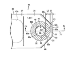
- FIG. 3 is a plan view of the eyeball portion 21, and FIG. 4 is a cross-sectional view of the eyeball portion 21.
- the eyeball portion 21 has a first plane 41 and a second plane 42 which are formed by plastic working such as forging and are parallel to each other.
- the second plane 42 is located on the opposite side of the first plane 41.
- the eyeball portion 21 has a circular through hole 45.
- the through hole 45 can be formed by a processing apparatus 100 (shown in FIGS. 6 to 10) described later.
- An inner surface (inner peripheral surface) 46 of the through hole 45 is perpendicular to the first plane 41 and the second plane 42.
- the through hole 45 penetrates the eyeball portion 21 in the thickness direction, and is open to both the first plane 41 and the second plane 42.
- a base portion of a connection member 31 (shown in FIGS. 1 and 2) such as a stabilizer link is inserted into the through hole 45.
- the connection member 31 is fixed to the eyeball portion 21 by a fixing screw member 31a such as a nut.
- the other eyeball portion 22 is similarly configured, and the connection member 32 is fixed to the eyeball portion 22 by a fixing screw member 32a.
- the eyeball portion 21 is formed by crushing the end portion of the steel pipe. For this reason, a tapered portion 47 is formed between the hollow arm portion 28 and the solid eyeball portion 21.
- the taper-shaped portion 47 has a shape in which the thickness gradually decreases from the arm portion 28 toward the eyeball portion 21, and has a hollow portion 47a inside.
- the eyeball portion 21 includes a trim portion 51 formed at the tip of the eyeball portion 21, a circular flat reference surface 52 (shown by hatching in FIG. 3), a tip-side bending portion 55, and a hole-side bending portion 60.
- the trim part 51 has the front end surface 50 cut
- the annular reference surface 52 is a part of the first plane 41 and is formed concentrically with the opening 45 a around the through hole 45.
- the distal end side curved portion 55 is formed at the edge of the trim portion 51.
- the hole side curved portion 60 is formed at the edge of the opening 45a.
- the trim part 51 is formed at the tip of the eyeball part 21.
- the distal end side bending portion 55 is formed between the trim portion 51 and the annular reference surface 52.
- the tip surface 50 of the eyeball portion 21 is perpendicular to the first plane 41 and the second plane 42.
- the thickness T1 of the eyeball portion 21 is, for example, 7 to 12 mm, but is different depending on the vehicle type.
- the flat annular reference surface 52 functions as a fastening surface to which the fixing connection member 31 such as a stabilizer link is fixed.
- the annular reference surface 52 has an annular shape centered on the center C 0 (shown in FIG. 4) of the through hole 45.
- the outer diameter R1 of the annular reference surface 52 is larger than the inner diameter R2 of the through hole 45.
- the annular reference surface 52 includes a trim-side flat portion 52 a located on the side closer to the trim portion 51 and an anti-trim-side flat portion 52 b located on the side far from the trim portion 51.
- the eyeball portion 21 is formed by crushing the end of the steel pipe by forging or the like. For this reason, a pressure contact portion 61 (indicated by a two-dot chain line in FIG. 4) is present on the inner surface of the steel pipe approximately at the center in the thickness direction of the eyeball portion 21.
- a tapered portion 47 is formed between the arm portion 28 and the eyeball portion 21.
- the accuracy of the tapered portion 47 has a processing limit, and it is inevitable that the shape varies somewhat. For this reason, when the annular reference surface 52 is formed in the vicinity of the tapered portion 47, the flatness of the anti-trimming flat portion 52b may be affected within a tolerance range.
- the distance L1 from the outer periphery Q1 of the annular reference surface 52 to the tip surface 50 is smaller than the distance L2 from the outer periphery Q1 of the annular reference surface 52 to the opening 45a. That is, the eyeball portion 21 of the present embodiment has a shorter length in the axis X2 direction of the eyeball portion 21 than a conventional general eyeball portion.
- the tip surface 50 of the eyeball portion 21 includes a cut surface 50a perpendicular to the axis X2 and cut surfaces 50b and 50c cut obliquely with respect to the axis X2. This is because there is a space restriction on the stabilizer mounting portion of the suspension system.
- the front end side curved portion 55 existing in the trim portion 51 is formed at the first corner portion C1 where the first plane 41 and the front end surface 50 intersect outside the outer periphery Q1 (shown in FIG. 3) of the annular reference surface 52. . That is, the distal end side bending portion 55 is formed between the outer periphery Q1 of the annular reference surface 52 and the distal end surface 50.
- the distal-side bending portion 55 has a thickness that decreases from the first plane 41 toward the distal end surface 50 over a first length H1 (shown in FIG. 4).
- the first length H1 varies depending on various conditions such as the temperature of the eyeball portion 21 when the trim portion 51 is cut and the thickness T1 of the eyeball portion 21, but is in the range of 2.0 to 3.5 mm, for example.
- the eyeball portion 21 of the present embodiment has a considerably shorter distance between the trim portion 51 and the annular reference surface 52 than a conventional general eyeball portion. That is, the distance L1 from the outer periphery Q1 of the annular reference surface 52 to the tip surface 50 is smaller than the distance L2 from the outer periphery Q1 of the annular reference surface 52 to the opening 45a (L1 ⁇ L2).
- the length of the distal end side bending portion 55 and the length of the hole side bending portion 60 are reduced by processing the eyeball portion 21 using the processing apparatus 100 shown in FIGS. 6 to 10. It turned out that it can be made considerably smaller than the conventional eyeball. In addition, by using the processing apparatus 100, an annular reference surface 52 having a target flatness could be obtained.
- the hole-side curved portion 60 existing at the edge of the through hole 45 is formed at the second corner portion C2 where the first plane 41 and the inner surface 46 of the through hole 45 intersect. That is, the hole-side curved portion 60 is formed on the entire periphery of the edge portion (opening 45a of the through hole 45) where the first plane 41 and the inner surface 46 intersect inside the inner periphery Q2 of the annular reference surface 52.
- the hole-side curved portion 60 includes a trim-side curved surface 60 a located on the side close to the trim portion 51 and an anti-trim-side curved surface 60 b located on the side far from the trim portion 51. Contains.
- the trimmed curved surface 60a is formed from the first plane 41 toward the inner surface 46 over the second length H2.
- the second length H2 is shorter than the length (first length H1) of the distal end side bending portion 55.
- the anti-trim-curved curved surface 60b is formed over the third length H3 from the first plane 41 toward the inner surface 46.
- the third length H3 is shorter than the second length H2.
- the first length H1 is 3 mm
- the second length H2 is 0.6 mm
- the third length H3 is 0.4 mm, for example.
- the curved surface between the trim-side curved surface 60a and the anti-trim-side curved surface 60b gradually decreases in length from the second length H2 to the third length H3.
- the trim-side curved surface 60a of the hole-side curved portion 60 decreases in thickness over the second length H2 (shown in FIG. 4) from the first plane 41 toward the inner surface 46. Further, the anti-trim-curved curved surface 60b decreases in thickness over the third length H3 from the first plane 41 toward the inner surface 46.
- the hole-side curved portion 60 is curved with a larger curvature than the tip-side curved portion 55 from the inner circumference Q ⁇ b> 2 of the annular reference surface 52 toward the inner surface 46 of the through hole 45. That is, the radius of curvature r2 of the trimmed curved surface 60a is smaller than the radius of curvature r1 of the distal end side curved portion 55.
- the anti-trim-side curved surface 60b is curved with a larger curvature than the trim-side curved surface 60a. That is, the curvature radius r3 of the anti-trimming curved surface 60b is smaller than the curvature radius r2 of the trimming curved surface 60a. Between the curved surface 60a near the trim and the curved surface 60b near the trim, the radius of curvature gradually decreases from the radius of curvature r2 to the radius of curvature r3.
- the eyeball portion 21 of the present embodiment has the distal end side curved portion 55 having the first length H1 outside the outer periphery Q1 of the annular reference surface 52.
- the distal end side bending portion 55 is formed at the first corner portion C ⁇ b> 1 where the first plane 41 and the distal end surface 50 intersect.
- the eyeball portion 21 has a hole-side curved portion 60 inside the inner periphery Q2 of the annular reference surface 52.
- the hole side curved portion 60 is formed at the second corner portion C2 where the first plane 41 and the inner surface 46 intersect.
- the hole-side curved portion 60 includes a trim-side curved surface 60a and an anti-trim-side curved surface 60b.
- the length (second length H2) of the trim-side curved surface 60a is smaller than the length (first length H1) of the distal-end-side curved portion 55, and the length (first length) of the anti-trim-side curved surface 60b. 3 (H1> H2> H3). That is, the length of the hole side bending portion 60 is smaller than the length of the distal end side bending portion 55.
- the length of the hole-side bending portion 60 is not more than the second length H2 and not less than the third length H3.
- the radius of curvature r2 of the trimmed curved surface 60a is smaller than the radius of curvature r1 of the distal curved portion 55 and larger than the radius of curvature r3 of the anti-trimmed curved surface 60b (r1> r2> r3). That is, the hole side bending portion 60 is bent with a larger curvature than the distal end side bending portion 55. Moreover, the distal-side curved portion 55 is formed outside the outer periphery Q1 of the annular reference surface 52, and the hole-side curved portion 60 is formed inside the inner periphery Q2 of the annular reference surface 52.
- the eyeball portion 21 By making the eyeball portion 21 into such a shape, it is possible to suppress the flatness of the annular reference surface 52 from being influenced by the distal end side bending portion 55 and the hole side bending portion 60, and the flatness of the annular reference surface 52 can be reduced. It was within the tolerance range. In particular, the annular reference surface 52 having a predetermined area and flatness is secured even for the eyeball portion 21 (L1 in FIG. 3 where L1 is smaller than L2) whose distance from the annular reference surface 52 to the trim portion 51 is small.
- L1 is the distance from the outer periphery Q1 of the annular reference surface 52 to the tip surface 50.
- L2 is a distance L2 from the outer periphery Q1 of the annular reference surface 52 to the opening 45a.
- the other eyeball portion 22 has a similar annular reference surface.
- the flatness of the annular reference surface 52 is within a tolerance range. However, microscopically, the annular reference surface 52 also has some unevenness and inclination.
- An anti-trimming flat portion 52 b is formed in the vicinity of the tapered portion 47 in a part of the annular reference surface 52 in the circumferential direction.
- the eyeball portion 21 has a flat shape due to a load applied during processing, but when the load is released after processing, the tapered portion 47 slightly returns to its original shape. For this reason, the flatness 52b near the anti-trim may be affected by the flatness even though it is within the tolerance range. That is, the anti-trim flat portion 52b may be affected by the tapered portion 47 more than the trim-flat portion 52a.
- the hole-side curved portion 60 includes the trim-side curved surface 60a and the anti-trim-side curved surface 60b.
- the anti-trim-side curved surface 60b is curved with a larger curvature (smaller radius of curvature) than the trim-side curved surface 60a.
- the length H3 of the anti-trimming curved surface 60b is smaller than the length H2 of the trimming curved surface 60a.
- the width S2 (shown in FIG. 4) of the flat portion 52b near the trim is slightly larger than the width S1 of the flat portion 52a near the trim.
- the annular reference surface 52 is slightly wider from the trim-side flat portion 52a having the width S1 toward the counter-trimming flat portion 52b having the width S2. Therefore, the area on the side closer to the non-trim flat portion 52b can be made slightly larger than the area on the side closer to the trim closer flat portion 52a. As a result, the minute shape variation of the flat portion 52b near the trim is alleviated, and the surface pressure received by the annular reference surface 52 as the fastening surface can be made more uniform.
- FIG. 5 schematically shows an eyeball portion 21 ′ according to the second embodiment.
- the eyeball portion 21 ′ includes a through hole 45, a trim portion 51, an annular reference surface 52, a tip side bending portion 55, and a hole side bending portion 60. It has.
- the annular reference surface 52 is formed concentrically around the opening 45 a of the through hole 45.
- the distal end side curved portion 55 is formed at the first corner C1 where the first plane 41 and the distal end surface 50 intersect outside the outer periphery Q1 of the annular reference surface 52.
- H ⁇ b> 1 in FIG. 5 indicates the length (first length) of the distal end side bending portion 55.
- the hole-side curved portion 60 is formed at the second corner C2 where the first plane 41 and the inner surface 46 intersect inside the inner periphery Q2 of the annular reference surface 52.
- the hole-side curved portion 60 includes a trim-side curved surface 60 a close to the trim portion 51 and an anti-trim-side curved surface 60 b far from the trim portion 51.
- H2 in FIG. 5 indicates the length (second length) of the trimmed curved surface 60a.
- H3 indicates the length (third length) of the anti-trimming curved surface 60b.
- the second length H2 is smaller than the first length H1.
- the third length H3 is smaller than the second length H2.
- the hole-side bending portion 60 is curved with a larger curvature (smaller curvature radius) than the distal-end-side bending portion 55.
- the anti-trim-side curved surface 60b is curved with a larger curvature (smaller radius of curvature) than the trim-side curved surface 60a.
- L1 is smaller than L2 in the same manner as the eyeball portion 21 of the first embodiment.
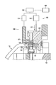
- FIGS. 6 to 10 show the movement of the processing apparatus 100 when processing the eyeball part in the order of steps.
- 6 to 10 show a case where one eyeball portion 21 is processed.
- the other eyeball portion 22 is processed in the same manner, the case where one eyeball portion 21 is processed will be representative. To explain.
- the processing apparatus 100 includes a base 101, a lower mold 102, an upper mold 103, a hydraulic drive stripper 104, a hydraulic unit 105, and a control unit 106.
- the base 101 is fixed to a factory floor or the like.
- the lower mold 102 is disposed on the base 101.
- the upper mold 103 and the hydraulic drive stripper 104 are respectively disposed above the lower mold 102.
- the lower mold 102 is provided with a work support part 110 on which the eyeball part 21 is placed and a lower blade 111.
- the upper die 103 is provided with an upper blade 120 and a punch 121.
- the upper blade 120 is paired with the lower blade 111.
- the eyeball portion 21 is pressurized between the work support portion 110 and the hydraulic pressure driving stripper 104.
- the upper blade 120 is lowered from the first position (shown in FIG. 6) toward the second position (shown in FIG. 8) toward the lower mold 102, whereby the trim portion 51 of the eyeball portion 21 is cut.
- the punch 121 can move in the vertical direction along with the upper blade 120 over the first position and the second position.
- the trim part 51 is cut by the lower blade 111 and the upper blade 120, and at the same time, the through hole 45 is formed in the eyeball part 21 by the punch 121. The For this reason, the positional relationship between the through hole 45 and the trim portion 51 does not vary, and the through hole 45 and the trim portion 51 can be formed with high accuracy.
- the hydraulic drive stripper 104 functions as a pressing member for pressing the eyeball portion 21.
- the hydraulic drive stripper 104 is formed with a vertical hole 125 into which the punch 121 is inserted.
- the hydraulic drive stripper 104 is moved in the vertical direction by the actuator 131.
- the hydraulic drive stripper 104 pressurizes the eyeball portion 21 with a predetermined hydraulic pressure P (shown in FIGS. 7 and 9).
- P shown in FIGS. 7 and 9
- the eyeball portion 21 is pressurized in the thickness direction between the hydraulic pressure driving stripper 104 and the workpiece support portion 110.
- An example of the hydraulic pressure supplied to the actuator 131 is 20 MPa (5 to 35 MPa), but other pressures may be used.
- the hydraulic unit 105 includes a first actuator 130 such as a hydraulic cylinder, a second actuator 131 such as a hydraulic cylinder, a hydraulic pressure supply source 132, and the like.
- the first actuator 130 moves the upper mold 103 in the vertical direction.
- the second actuator 131 moves the hydraulic drive stripper 104 in the vertical direction.
- the hydraulic pressure supply source 132 includes a hydraulic pump that supplies hydraulic pressure to the actuators 130 and 131, a distribution valve, and the like.
- the hydraulic pressure supply source 132 is controlled in a predetermined sequence by the control unit 106 in which an electrical control program and control data are stored.
- the control unit 106 controls the actuator 130 so that the upper mold 103 moves between the first position and the second position. For example, by moving the upper mold 103 from the first position toward the second position, the trim portion 51 is cut by the lower blade 111 and the upper blade 120, and the through hole 45 is punched by the punch 121. .
- the control unit 106 controls the actuator 131 such that the hydraulic drive stripper 104 is pressed against the eyepiece 21 with a constant hydraulic pressure P while the upper mold 103 moves from the first position toward the second position. .
- the control unit 106 controls the actuator 131 so as to maintain the hydraulic pressure P of the hydraulic drive stripper 104 even while the upper mold 103 is raised and returned from the second position to the first position. For this reason, while the upper mold
- the eyeball part processing method processes the eyeball part 21 through the following steps. Since the other eyeball part 22 is processed similarly, the case where one eyeball part 21 is processed will be described below.
- the eyeball part 21 of the heated stabilizer 10 is placed on the work support part 110 of the lower mold 102.
- the temperature of the heated stabilizer 10 is, for example, 850 to 1150 ° C.
- the hydraulic drive stripper 104 is moved (lowered) in the direction indicated by the arrow A ⁇ b> 1 from above the eyeball portion 21. Then, the hydraulic drive stripper 104 is pressurized toward the eyeball portion 21 by the hydraulic pressure P, so that the eyeball portion 21 is sandwiched between the hydraulic drive stripper 104 and the work support portion 110 in the thickness direction.
- the upper mold 103 is moved (lowered) in the direction indicated by the arrow A ⁇ b> 2 toward the lower mold 102 in a state where the eyeball portion 21 is pressurized by the hydraulic drive stripper 104.
- the upper blade 120 and the punch 121 are lowered simultaneously, the trim portion 51 is cut between the lower blade 111 and the upper blade 120, and the through hole 45 is formed by the punch 121.
- the distal end side curved portion 55 is formed on the cut surface of the trim portion 51 that is in contact with the upper blade 120 (near the upper edge of the trim portion 51).
- the hole-side curved portion 60 is formed at the inner edge (around the opening 45a) of the through hole 45 in contact with the punch 121.
- the upper mold 103 moves (rises) in the direction indicated by the arrow A3. While the upper mold 103 is raised to the first position, the eyeball portion 21 is continuously pressurized under the fluid pressure P by maintaining the fluid pressure P supplied to the fluid pressure driven stripper 104.
- the fluid pressure of the hydraulic drive stripper 104 is released by pressurizing the eyeball portion 21 until then.
- the hydraulic drive stripper 104 moves (rises) in the direction indicated by the arrow A4
- the hydraulic drive stripper 104 is retracted from the eyeball portion 21.
- the processing method of the present embodiment is effective in improving the accuracy of the annular reference surface 52. That is, after the through hole 45 and the trim portion 51 are formed, the hydraulic pressure P supplied to the hydraulic pressure driving stripper 104 is maintained for a certain period of time while the upper mold 103 is raised from the second position to the first position. The part 21 is continuously pressurized under the hydraulic pressure P. By doing so, the length H1 (shown in FIGS. 4 and 5) of the distal end side bending portion 55 and the lengths H2 and H3 of the hole side bending portion 60 can be reduced, and the radius of curvature of the distal end side bending portion 55 can be reduced. The curvature radii r2 and r3 of r1 and the hole-side curved portion 60 could also be reduced.
- a test was also performed for processing the eyeball using a conventional processing apparatus (comparative example).
- the processing apparatus of the comparative example has a movable stripper that holds the eyeball portion by the repulsive load of the coil spring.
- the repulsive load of the coil spring decreased as the movable stripper rose, and the repulsive load of the coil spring became zero in a short time.
- the distal end side curved portion and the hole side curved portion of the eyeball portion processed by the conventional processing apparatus were longer than the distal end side curved portion and the hole side curved portion of the eyeball portion of this embodiment, and the curvature radius was also large.
- burrs may occur on the second flat surface 42 side of the tip surface 50.
- a burr may be generated on the second flat surface 42 side of the inner surface 46.
- the steel material as the stabilizer material may be a solid material in addition to the hollow material (steel pipe).
- the specific shape and arrangement of the stabilizer main body and the eyeball can be variously changed according to the specifications of the suspension mechanism of the vehicle.
- the specific shapes of the annular reference surface (fastening surface) of the eyeball portion, the distal end side bending portion, and the hole side bending portion are not limited to the above embodiment.
Abstract
目玉部(21)の貫通孔(45)の周りに環状基準面(52)が形成されている。環状基準面(52)の外側で、第1平面(41)と先端面(50)とが交わる第1の角部(C1)に、先端側湾曲部(55)が形成されている。先端側湾曲部(55)は、第1平面(41)から先端面(50)に向かって長さ(H1)にわたり厚さが減少している。環状基準面(52)の内側で、第1平面(41)と貫通孔(45)の内面(46)とが交わる第2の角部(C2)に、内面(46)に向かって厚さが減少する孔側湾曲部(60)形成されている。孔側湾曲部(60)の長さは、先端側湾曲部(55)の長さ(H1)よりも小さい。孔側湾曲部(60)は先端側湾曲部(55)よりも大きな曲率(小さな曲率半径)で湾曲している。
Description
この発明は、自動車等の車両の懸架機構部に配置される車両用スタビライザと、スタビライザの目玉部の加工装置と、目玉部の加工方法に関する。
車両の懸架機構部に配置されるスタビライザは、鋼管あるいは中実の棒状の鋼材からなり、車両の幅方向に延びるトーション部(ねじり部)と、トーション部の両端に曲がり部を介して連なる一対のアーム部(腕部)とを有している。各アーム部の先端に、それぞれ目玉部が形成されている。懸架機構部の一例では、スタビライザのトーション部がゴムブッシュを有する支持部を介して車体に支持される。そして目玉部がスタビリンク等の接続部材を介してサスペンションアーム等に連結される。懸架機構部に組付けられたスタビライザは、車体のローリング挙動に対して前記アーム部や曲がり部およびトーション部がばねとして機能することにより、車両のロール剛性を高めることができる。
例えば特許文献1や特許文献2に記載されているスタビライザは、鋼管の両端をアプセット加工によって潰すことにより、一対の目玉部が形成されている。目玉部にはそれぞれ平坦な締結面が形成されている。各締結面に貫通孔が形成されている。貫通孔にスタビリンク等の接続部材が挿入される。この接続部材を介して目玉部がサスペンションアーム等の懸架機構部材に接続される。
スタビライザの目玉部をアプセット加工等の塑性加工によって成形する場合、目玉部の形状を塑性加工のみによって正確に規制することには限界がある。例えば目玉部の先端面と貫通孔との位置関係や、締結面の平面度および平行度を塑性加工のみによって正確に規制することは難しい。しかも目玉部の先端面や貫通孔の縁に、剪断加工によるだれ(shear creep)が生じることも避けられない。このため目玉部の精度を高めるには機械加工等の仕上げ加工が必要となり、その分だけ手間がかかりコストが高くなる原因となる。
目玉部の締結面にはスタビリンク等の接続部材がナット等のねじ部材によって固定される。例えば締結面に加わる面圧を均一にするために、締結面の平面度や平行度を精度良く管理することが要求されている。従来のスタビライザの目玉部は、成形時の加工上の限界等により、高精度の締結面を得ることが難しかった。懸架機構の仕様によっては、目玉部の先端から貫通孔までの距離が短い(目玉部の長さが小さい)スタビライザが望まれることがある。このような目玉部では、例えば目玉部の先端から貫通孔までの距離や締結面の平面度および平行度を精度良く管理することが難しく、所定の締結面を得られないことがあった。
従って本発明の目的は、精度の高い締付面を有する目玉部を備えた車両用スタビライザと、目玉部の加工装置と、目玉部の加工方法を提供することにある。
1つの実施形態は、棒状の鋼材(鋼管あるいは中実の鋼棒)からなる車両用スタビライザであって、車両の幅方向に延びるトーション部と、該トーション部の両端からそれぞれ曲がり部を介して連なる一対のアーム部と、一対の目玉部を有している。目玉部は、それぞれ、互いに平行な第1平面および第2平面と、前記各目玉部の先端に位置し前記第1平面および前記第2平面に対し直角な先端面を有したトリム部と、前記第1平面および前記第2平面に対し直角な内面を有し前記第1平面および前記第2平面に開口する貫通孔と、前記第1平面の一部で前記貫通孔の開口の周りに形成された平坦な環状基準面と、先端側湾曲部と、孔側湾曲部とを具備している。前記先端側湾曲部は、前記環状基準面の外側で、前記第1平面と前記先端面とが交わる第1の角部に形成され、前記第1平面から前記先端面に向かって第1の長さにわたり厚さが減少する。前記孔側湾曲部は、前記環状基準面の内側で、前記第1平面と前記貫通孔の内面とが交わる第2の角部に前記開口の全周に形成され、前記第1平面から前記内面に向かって前記第1の長さよりも短い長さにわたり厚さが減少しかつ前記先端側湾曲部よりも大きな曲率で湾曲している。
この実施形態において、前記環状基準面の外周から前記先端面までの距離が、前記環状基準面の外周から前記開口までの距離よりも小さくてもよい。また前記孔側湾曲部が、前記トリム部寄りの位置に形成された第2の長さのトリム寄り湾曲面と、前記トリム部から遠い側に形成された第3の長さの反トリム寄り湾曲面とを含み、前記第3の長さが前記第2の長さよりも小さくてもよい。さらにこの実施形態において、前記反トリム寄り湾曲面の曲率が前記トリム寄り湾曲面の曲率よりも大きくてもよい。
本発明によれば、トリム部を切断した際に形成される先端側湾曲部や貫通孔を打抜いた際に形成される孔側湾曲部が目玉部の貫通孔の周りに存する環状基準面(締結面)に影響することを抑制でき、精度の高い締結面を有した車両用スタビライザを提供することができる。
以下に第1の実施形態に係る目玉部を備えた車両用スタビライザについて、図1から図4を参照して説明する。
図1は、車両用スタビライザ(これ以降は単にスタビライザと称する)10を備えた車両11の一部を示している。スタビライザ10は、車両11の車体12の下部に配置される懸架機構部の一部をなしている。図2はスタビライザ10の一例を示す平面図である。
図1は、車両用スタビライザ(これ以降は単にスタビライザと称する)10を備えた車両11の一部を示している。スタビライザ10は、車両11の車体12の下部に配置される懸架機構部の一部をなしている。図2はスタビライザ10の一例を示す平面図である。
スタビライザ10は棒状の鋼材(例えば鋼管)からなり、スタビライザ本体部20と、スタビライザ本体部20の両端に一体に形成された一対の目玉部21,22とを含んでいる。スタビライザ10は、鋼管の端部を鍛造等の塑性加工によって平坦に潰すことにより目玉部21,22が形成されている。このためこのスタビライザ10は、鋼管の形がほぼそのまま残る中空のスタビライザ本体部20と、スタビライザ本体部20の両端部に形成された中実の目玉部21,22とを有している。
スタビライザ本体部20は、車体12の幅方向(図1に矢印W1で示す方向)に延びるトーション部25と、一対のアーム部28,29とを含んでいる。アーム部28,29は、それぞれ、トーション部25の両端からそれぞれ曲がり部26,27を介して連なっている。
スタビライザ10は平面的な形状に限ることはない。例えば3次元的な曲げ形状も含めて、トーション部25に1箇所以上の曲げ部、あるいはアーム部28,29に1箇所以上の曲げ部を有していてもよい。また、曲がり部26,27が3次元的な曲げ形状を有していてもよいなど、車両11の種類に応じて種々な曲げ形状をなしている。スタビライザ10の表面には、鋼材の防錆のための塗装が施されている。
このスタビライザ10は対称軸X1(図2に示す)を中心に左右対称形であり、両端に目玉部21,22を有している。目玉部21,22は、それぞれ、スタビリンク等の棒状の接続部材31,32を介して、懸架機構部のサスペンションアーム等に接続される。
トーション部25は、ゴムブッシュ等を備えた一対の支持部33,34を介して、例えば車体12の一部(例えばクロスメンバ等)に支持される。車両11がカーブを走行する際などに、アーム部28,29に互いに逆相の力が入力すると、アーム部28,29に曲げの力がかかるとともに、曲がり部26,27に曲げとねじりの力がかかる。その結果、トーション部25がねじられて反発荷重が発生することにより、車体12のローリング挙動が抑制される。
本実施形態のスタビライザ10の材料は鋼管であり、曲げ加工機等によってスタビライザ本体部20が所定の形状に成形されている。鋼材の一例は、焼入れ等の熱処理によって強度を向上させることのできる鋼種、例えば材質ASB25N等の鋼管である。鋼材の両端を鍛造等の塑性加工によって潰すことにより、目玉部21,22が形成されている。なお、中実のスタビライザの場合には、材料に中実の鋼製のロッドが使用される。
目玉部21,22は、対称軸X1(図2に示す)を境に左右対称形であるため、これ以降は一方の目玉部21(図3と図4に示す)を代表して説明する。他方の目玉部22は一方の目玉部21と実質的に同様に構成されている。
図3は目玉部21の平面図、図4は目玉部21の断面図である。図4に示されるように目玉部21は、鍛造等の塑性加工によって形成された互いに平行な第1平面41と第2平面42とを有している。第2平面42は第1平面41の反対側に位置している。またこの目玉部21は円形の貫通孔45を有している。貫通孔45は、後述する加工装置100(図6から図10に示す)によって形成することができる。貫通孔45の内面(内周面)46は、第1平面41と第2平面42に対して直角である。
貫通孔45は目玉部21を厚さ方向に貫通し、第1平面41と第2平面42との双方に開口している。貫通孔45にスタビリンク等の接続部材31(図1と図2に示す)の基部が挿入される。接続部材31は、ナット等の固定用ねじ部材31aによって目玉部21に固定される。他方の目玉部22も同様に構成され、接続部材32が固定用ねじ部材32aによって目玉部22に固定される。
本実施形態のスタビライザ10は、鋼管の端部を潰すことによって目玉部21が形成される。このため中空のアーム部28と中実の目玉部21との間に、テーパ形状部47が形成されている。テーパ形状部47は、アーム部28から目玉部21に向かって厚さが次第に小さくなる形状であり、内部に中空部47aを有している。
この目玉部21は、目玉部21の先端に形成されたトリム部51と、円形で平坦な環状基準面52(図3にハッチングで示す)と、先端側湾曲部55と、孔側湾曲部60とを含んでいる。トリム部51は、加工装置100(図6から図10に示す)によって切断された先端面50を有している。環状基準面52は、第1平面41の一部で、貫通孔45の周りに開口45aと同心円状に形成されている。先端側湾曲部55はトリム部51の縁に形成されている。孔側湾曲部60は開口45aの縁に形成されている。
トリム部51は目玉部21の先端に形成されている。先端側湾曲部55は、トリム部51と環状基準面52との間に形成されている。図4に示されるように目玉部21の厚さ方向の断面において、目玉部21の先端面50は、第1平面41および第2平面42に対し直角である。目玉部21の厚さT1は例えば7~12mmであるが、車種によって異なる値である。
平坦な環状基準面52は、スタビリンク等の固定用の接続部材31が固定される締結面として機能する。環状基準面52は貫通孔45の中心C0(図4に示す)を中心とする円環状をなしている。環状基準面52の外径R1は貫通孔45の内径R2よりも大きい。環状基準面52は、トリム部51に近い側に位置するトリム寄り平坦部52aと、トリム部51から遠い側に位置する反トリム寄り平坦部52bとを含んでいる。
鋼管の端部を鍛造等によって潰すことにより目玉部21が形成される。このため目玉部21の厚さ方向のほぼ中央に、鋼管内面の圧接部61(図4に2点鎖線で示す)が存在する。鋼管の端部が潰されることにより、アーム部28と目玉部21との間にテーパ形状部47が形成される。テーパ形状部47の精度には加工上の限界があり、形状が多少ばらつくことが避けられない。このためテーパ形状部47の近傍に環状基準面52が形成されている場合には、反トリム寄り平坦部52bの平面度が公差の範囲内で影響を受ける可能性がある。
図3に示されるように環状基準面52の外周Q1から先端面50までの距離L1は、環状基準面52の外周Q1から開口45aまでの距離L2よりも小さい。すなわち本実施形態の目玉部21は、目玉部21の軸線X2方向の長さが、従来の一般的な目玉部よりも短い。しかも目玉部21の先端面50は、軸線X2に対し直角な切断面50aと、軸線X2に対し斜めに切断された切断面50b,50cとを含んでいる。これは懸架装置のスタビライザ取付部にスペース的な制約があることによる。
トリム部51に存する先端側湾曲部55は、環状基準面52の外周Q1(図3に示す)の外側で第1平面41と先端面50とが交わる第1の角部C1に形成されている。つまりこの先端側湾曲部55は、環状基準面52の外周Q1と先端面50との間に形成されている。先端側湾曲部55は、第1平面41から先端面50に向かって、第1の長さH1(図4に示す)にわたり厚さが減少している。第1の長さH1は、トリム部51を切断する際の目玉部21の温度や目玉部21の厚さT1等の諸条件によって異なるが、例えば2.0~3.5mmの範囲である。
目玉部21の厚さT1が大きいほど、先端側湾曲部55の長さ(第1の長さH1)が大きくなる傾向がある。本実施形態の目玉部21は、従来の一般的な目玉部と比較して、トリム部51と環状基準面52との間の距離がかなり近い。すなわち環状基準面52の外周Q1から先端面50までの距離L1が、環状基準面52の外周Q1から開口45aまでの距離L2よりも小さい(L1<L2)。
本発明者達が鋭意研究したところ、図6から図10に示す加工装置100を用いて目玉部21の加工を行うことにより、先端側湾曲部55の長さと孔側湾曲部60の長さを従来の目玉部よりもかなり小さくすることができることがわかった。しかも加工装置100を用いることにより、目標とする平面度の環状基準面52を得ることができた。
貫通孔45の縁に存する孔側湾曲部60は、第1平面41と貫通孔45の内面46とが交わる第2の角部C2に形成されている。すなわち孔側湾曲部60は、環状基準面52の内周Q2の内側において、第1平面41と内面46とが交わる縁部(貫通孔45の開口45a)の全周に形成されている。
図4に模式的に示すように、孔側湾曲部60は、トリム部51に近い側に位置するトリム寄り湾曲面60aと、トリム部51から遠い側に位置する反トリム寄り湾曲面60bとを含んでいる。トリム寄り湾曲面60aは、第1平面41から内面46に向かって第2の長さH2にわたり形成されている。第2の長さH2は先端側湾曲部55の長さ(第1の長さH1)よりも短い。
反トリム寄り湾曲面60bは、第1平面41から内面46に向かって第3の長さH3にわたり形成されている。第3の長さH3は第2の長さH2よりも短い。例えば第1の長さH1が3mmであるのに対し、第2の長さH2は例えば0.6mm、第3の長さH3は例えば0.4mmである。トリム寄り湾曲面60aと反トリム寄り湾曲面60bとの間の湾曲面は、第2の長さH2から第3の長さH3へと次第に長さが短くなっている。
すなわち孔側湾曲部60のトリム寄り湾曲面60aは、第1平面41から内面46に向かって、第2の長さH2(図4に示す)にわたり厚さが減少している。また反トリム寄り湾曲面60bは、第1平面41から内面46に向かって、第3の長さH3にわたり厚さが減少している。
図4に示されるように孔側湾曲部60は、環状基準面52の内周Q2から貫通孔45の内面46に向かって、先端側湾曲部55よりも大きな曲率で湾曲している。すなわちトリム寄り湾曲面60aの曲率半径r2は先端側湾曲部55の曲率半径r1よりも小さい。しかも反トリム寄り湾曲面60bは、トリム寄り湾曲面60aよりも大きな曲率で湾曲している。すなわち反トリム寄り湾曲面60bの曲率半径r3は、トリム寄り湾曲面60aの曲率半径r2よりも小さい。トリム寄り湾曲面60aと反トリム寄り湾曲面60bとの間は、曲率半径r2から曲率半径r3へと次第に曲率半径が小さくなる形状となっている。
このように本実施形態の目玉部21は、環状基準面52の外周Q1の外側に、第1の長さH1の先端側湾曲部55を有している。先端側湾曲部55は、第1平面41と先端面50とが交わる第1の角部C1に形成されている。またこの目玉部21は、環状基準面52の内周Q2の内側に孔側湾曲部60を有している。孔側湾曲部60は、第1平面41と内面46とが交わる第2の角部C2に形成されている。
孔側湾曲部60は、トリム寄り湾曲面60aと反トリム寄り湾曲面60bとを含んでいる。トリム寄り湾曲面60aの長さ(第2の長さH2)は先端側湾曲部55の長さ(第1の長さH1)よりも小さく、かつ、反トリム寄り湾曲面60bの長さ(第3の長さH3)よりも大きい(H1>H2>H3)。すなわち孔側湾曲部60の長さは先端側湾曲部55の長さよりも小さい。孔側湾曲部60の長さは、第2の長さH2以下、第3の長さH3以上である。トリム寄り湾曲面60aの曲率半径r2は先端側湾曲部55の曲率半径r1よりも小さく、かつ、反トリム寄り湾曲面60bの曲率半径r3よりも大きい(r1>r2>r3)。すなわち孔側湾曲部60は、先端側湾曲部55よりも大きな曲率で湾曲している。しかも先端側湾曲部55は環状基準面52の外周Q1の外側に形成され、かつ、孔側湾曲部60は環状基準面52の内周Q2の内側に形成されている。
目玉部21をこのような形状とすることにより、環状基準面52の平面度が先端側湾曲部55と孔側湾曲部60とによって影響を受けることを抑制でき、環状基準面52の平面度を公差の範囲に収めることができた。特に、環状基準面52からトリム部51までの距離が小さい目玉部21(図3中のL1がL2よりも小さい目玉部)であっても、所定の面積と平面度の環状基準面52を確保することができた。L1は環状基準面52の外周Q1から先端面50までの距離である。L2は環状基準面52の外周Q1から開口45aまでの距離L2である。他方の目玉部22も同様の環状基準面を有している。
環状基準面52の平面度は公差の範囲にある。しかし微視的には環状基準面52にも多少の凹凸や傾斜が存在する。環状基準面52の周方向の一部でテーパ形状部47の近傍には反トリム寄り平坦部52bが形成されている。目玉部21は加工時に加わる荷重によって扁平な形状となるが、加工後に荷重が解放されるとテーパ形状部47が僅かに元の形状に戻ろうとする。このため特に反トリム寄り平坦部52bは、公差の範囲内とはいえ平面度が影響を受ける可能性がある。つまり反トリム寄り平坦部52bは、トリム寄り平坦部52aよりも、テーパ形状部47の影響を受ける可能性がある。
前記したように孔側湾曲部60は、トリム寄り湾曲面60aと反トリム寄り湾曲面60bとを含んでいる。反トリム寄り湾曲面60bはトリム寄り湾曲面60aよりも大きな曲率(小さな曲率半径)で湾曲している。しかも反トリム寄り湾曲面60bの長さH3はトリム寄り湾曲面60aの長さH2よりも小さい。このため反トリム寄り平坦部52bの幅S2(図4に示す)は、トリム寄り平坦部52aの幅S1よりも若干大きくなる。
つまりこの環状基準面52は、幅S1のトリム寄り平坦部52aから幅S2の反トリム寄り平坦部52bに向かって僅かに広くなる。よって反トリム寄り平坦部52b側の面積をトリム寄り平坦部52a側の面積よりも若干広くとれる。このことにより、反トリム寄り平坦部52bの微小な形状ばらつきが緩和され、締結面としての環状基準面52が受ける面圧をさらに均等にすることができる。
図5は第2の実施形態に係る目玉部21´を模式的に示している。この目玉部21´は、第1の実施形態の目玉部21と同様に、貫通孔45と、トリム部51と、環状基準面52と、先端側湾曲部55と、孔側湾曲部60とを具備している。環状基準面52は、貫通孔45の開口45aの周りに同心円状に形成されている。先端側湾曲部55は、環状基準面52の外周Q1の外側で、第1平面41と先端面50とが交わる第1の角部C1に形成されている。図5中のH1は、先端側湾曲部55の長さ(第1の長さ)を示している。孔側湾曲部60は、環状基準面52の内周Q2の内側で、第1平面41と内面46とが交わる第2の角部C2に形成されている。
孔側湾曲部60は、トリム部51に近いトリム寄り湾曲面60aと、トリム部51から遠い側の反トリム寄り湾曲面60bとを含んでいる。図5中のH2は、トリム寄り湾曲面60aの長さ(第2の長さ)を示している。H3は、反トリム寄り湾曲面60bの長さ(第3の長さ)を示している。第2の長さH2は第1の長さH1よりも小さい。第3の長さH3は第2の長さH2よりも小さい。第1の実施形態と同様に、孔側湾曲部60は、先端側湾曲部55よりも大きな曲率(小さな曲率半径)で湾曲している。反トリム寄り湾曲面60bはトリム寄り湾曲面60aよりも大きな曲率(小さな曲率半径)で湾曲している。
図5中のL1は、環状基準面52の外周Q1から先端面50までの距離を示している。L2は、環状基準面52の外周Q1から開口45aまでの距離を示している。この目玉部21´は、第1の実施形態の目玉部21と同様に、L1がL2よりも小さい。
次に、図6から図10を参照して目玉部の加工装置100について説明する。図6から図10は、目玉部を加工する際の加工装置100の動きを工程順に示している。なお、図6から図10は一方の目玉部21を加工する場合を示しているが、他方の目玉部22も同様に加工されるため、これ以降は一方の目玉部21を加工する場合を代表して説明する。
加工装置100は、基台(ベース)101と、下型102と、上型103と、液圧駆動ストリッパ104と、液圧ユニット105と、制御部106とを備えている。基台101は、工場のフロア等に固定されている。下型102は、基台101上に配置されている。上型103と液圧駆動ストリッパ104とは、それぞれ下型102の上方に配置されている。下型102には、目玉部21を載置するワーク支持部110と、下刃111とが設けられている。
上型103に上刃120とパンチ121が設けられている。上刃120は、下刃111と対をなしている。目玉部21がワーク支持部110と液圧駆動ストリッパ104との間で加圧される。上刃120が下型102に向けて第1の位置(図6に示す)から第2の位置(図8に示す)まで降下することにより、目玉部21のトリム部51が切断される。
パンチ121は、上刃120と共に、第1の位置と第2の位置とにわたって上下方向に移動することができる。上型103が下型102に向かって第2の位置まで降下すると、下刃111と上刃120とによってトリム部51が切断されると同時に、パンチ121によって目玉部21に貫通孔45が形成される。このため貫通孔45とトリム部51との位置関係がばらつくことがなく、高い精度で貫通孔45とトリム部51とを形成することができる。
液圧駆動ストリッパ104は目玉部21を押さえるための押さえ部材として機能する。液圧駆動ストリッパ104には、パンチ121が挿入される上下方向の孔125が形成されている。液圧駆動ストリッパ104は、アクチュエータ131によって上下方向に移動する。上型103が第2の位置まで降下した状態において、液圧駆動ストリッパ104が所定圧力の液圧P(図7と図9に示す)で目玉部21を加圧する。これにより液圧駆動ストリッパ104とワーク支持部110との間で目玉部21が厚さ方向に加圧される。アクチュエータ131に供給する液圧の一例は20MPa(5~35MPa)であるが、これ以外の圧力であってもよい。
液圧ユニット105は、油圧シリンダ等の第1のアクチュエータ130と、油圧シリンダ等の第2のアクチュエータ131と、液圧供給源132などを含んでいる。第1のアクチュエータ130は上型103を上下方向に移動させる。第2のアクチュエータ131は、液圧駆動ストリッパ104を上下方向に移動させる。液圧供給源132は、アクチュエータ130,131に液圧を供給する油圧ポンプや分配弁等を備えている。液圧供給源132は、電気的な制御プログラムと制御用のデータが格納された制御部106によって、所定のシーケンスで制御される。
制御部106は、上型103が第1の位置と第2の位置との間で移動するようにアクチュエータ130を制御する。例えば上型103を第1の位置から第2の位置に向かって移動させることにより、下刃111と上刃120とによってトリム部51が切断されるとともに、パンチ121によって貫通孔45が打抜かれる。
制御部106は、上型103が第1の位置から第2の位置に向かって移動する間、液圧駆動ストリッパ104を一定の液圧Pで目玉部21に押付けるようにアクチュエータ131を制御する。しかも制御部106は、上型103が第2の位置から第1の位置まで上昇復帰する間も、液圧駆動ストリッパ104の液圧Pを維持するようにアクチュエータ131を制御する。このため上型103が第2の位置から第1の位置まで移動する間は、液圧Pによる目玉部21の加圧が継続される。制御部106は、上型103が第1の位置に復帰した状態において、それまで目玉部21を加圧していた液圧を解除するとともに、液圧駆動ストリッパ104を目玉部21の上方に退避させる機能も有している。
本実施形態に係る目玉部の加工方法は、下記の工程を経て目玉部21を加工する。他方の目玉部22も同様に加工されるため、一方の目玉部21を加工する場合について以下に説明する。
(1) 図6に示すように、加熱されたスタビライザ10の目玉部21を下型102のワーク支持部110に載置する。加熱されたスタビライザ10の温度は、例えば850~1150℃である。
(2) 図7に示すように目玉部21の上方から液圧駆動ストリッパ104を矢印A1で示す方向に移動(降下)させる。そして液圧駆動ストリッパ104を液圧Pによって目玉部21に向けて加圧することにより、目玉部21を液圧駆動ストリッパ104とワーク支持部110との間で厚さ方向に挟む。
(3) 図8に示すように、目玉部21が液圧駆動ストリッパ104によって加圧された状態において、上型103を下型102に向けて矢印A2で示す方向に移動(降下)させる。この動作により、上刃120とパンチ121が同時に降下し、下刃111と上刃120との間でトリム部51が切断されるとともに、パンチ121によって貫通孔45が形成される。上刃120によってトリム部51が切断される際に、上刃120と接するトリム部51の切断面(トリム部51の上縁付近)に先端側湾曲部55が形成される。またパンチ121によって貫通孔45が打抜かれる際に、パンチ121と接する貫通孔45の内面の縁(開口45aの周り)に孔側湾曲部60が形成される。
(4) 図9に示すように、貫通孔45とトリム部51とが形成されたのち、上型103が矢印A3で示す方向に移動(上昇)する。上型103が第1の位置まで上昇する間、液圧駆動ストリッパ104に供給する液圧Pを維持することによって、目玉部21を液圧Pのもとで加圧し続ける。
(5) 図10に示すように、上型103が第1の位置まで上昇すると、それまで目玉部21を加圧していて液圧駆動ストリッパ104の液圧が解除される。液圧駆動ストリッパ104が矢印A4で示す方向に移動(上昇)することにより、液圧駆動ストリッパ104が目玉部21から退避する。
本発明者達が鋭意研究した結果、環状基準面52の精度を高める上で、本実施形態の加工方法が有効であることがわかった。すなわち貫通孔45とトリム部51とが形成されたのち上型103が第2の位置から第1の位置まで上昇する間、液圧駆動ストリッパ104に供給する液圧Pを一定時間維持し、目玉部21を液圧Pのもとで加圧し続ける。こうすることにより、先端側湾曲部55の長さH1(図4と図5に示す)と孔側湾曲部60の長さH2,H3を小さくすることができ、先端側湾曲部55の曲率半径r1と孔側湾曲部60の曲率半径r2,r3も小さくすることができた。
比較のために、従来の加工装置(比較例)を用いて目玉部を加工する場合についても試験を行った。比較例の加工装置は、コイルばねの反発荷重によって目玉部を押さえる可動ストリッパを有している。この比較例では、可動ストリッパが上昇するにつれてコイルばねの反発荷重が減少し、短時間でコイルばねの反発荷重がゼロになってしまった。従来の加工装置によって加工された目玉部の先端側湾曲部と孔側湾曲部は、本実施形態の目玉部の先端側湾曲部と孔側湾曲部よりも長く、曲率半径も大きかった。
なお、下刃111と上刃120とによってトリム部51を剪断した際に、先端面50の第2平面42側にバリが生じることがある。またパンチ121によって貫通孔45を打抜いた際に、内面46の第2平面42側にバリが生じることもある。これらのバリは、第2平面に研磨あるいは研削等の仕上げの機械加工を行うことによって除かれる。
本発明を実施するに当たり、スタビライザの材料である鋼材は中空材(鋼管)以外に中実材であってもよい。またスタビライザ本体部や目玉部の具体的な形状や配置等を車両の懸架機構部の仕様に応じて種々に変更して実施できることは言うまでもない。目玉部の環状基準面(締結面)や先端側湾曲部および孔側湾曲部の具体的な形状も前記実施形態に限定されるものではない。
10…スタビライザ、20…スタビライザ本体部、21,22…目玉部、25…トーション部、26,27…曲がり部、28,29…アーム部、41…第1平面、42…第2平面、45…貫通孔、45a…開口、46…内面、47…テーパ形状部、50…先端面、51…トリム部、52…環状基準面(締結面)、52a…トリム寄り平坦部、52b…反トリム寄り平坦部、Q1…環状基準面の外周、55…先端側湾曲部、60…孔側湾曲部、60a…トリム寄り湾曲面、60b…反トリム寄り湾曲面、C1…第1の角部、C2…第2の角部、H1…第1の長さ、H2…第2の長さ、H3…第3の長さ、100…加工装置、101…基台、102…下型、103…上型、104…液圧駆動ストリッパ、105…液圧ユニット、106…制御部、110…ワーク支持部、111…下刃、120…上刃、121…パンチ。
Claims (8)
- 両端に目玉部(21)(22)を有した車両用スタビライザであって、
前記目玉部(21)(22)が、それぞれ、
互いに平行な第1平面(41)および第2平面(42)と、
前記各目玉部(21)(22)の先端に位置し、前記第1平面(41)および前記第2平面(42)に対し直角な先端面(50)を有したトリム部(51)と、
前記第1平面(41)および前記第2平面(42)に対し直角な内面(46)を有し前記第1平面(41)および前記第2平面(42)に開口する貫通孔(45)と、
前記第1平面(41)の一部で前記貫通孔(45)の開口(45a)の周りに形成された平坦な環状基準面(52)と、
前記環状基準面(52)の外側で、前記第1平面(41)と前記先端面(50)とが交わる第1の角部(C1)に形成され、前記第1平面(41)から前記先端面(50)に向かって第1の長さ(H1)にわたり厚さが減少する先端側湾曲部(55)と、
前記環状基準面(52)の内側で、前記第1平面(41)と前記貫通孔(45)の内面(46)とが交わる第2の角部(C2)に前記開口(45a)の全周に形成され、前記第1平面(41)から前記内面(46)に向かって前記第1の長さ(H1)よりも短い長さにわたり厚さが減少しかつ前記先端側湾曲部(55)よりも大きな曲率で湾曲する孔側湾曲部(60)と、
を具備したことを特徴とする車両用スタビライザ。 - 請求項1の車両用スタビライザにおいて、
前記環状基準面(52)の外周(Q1)から前記先端面(50)までの距離(L1)が、前記環状基準面(52)の外周(Q1)から前記開口(45a)までの距離(L2)よりも小さいことを特徴とする車両用スタビライザ。 - 請求項1の車両用スタビライザにおいて、
前記孔側湾曲部(60)が、前記トリム部(51)寄りの位置に形成された第2の長さ(H2)のトリム寄り湾曲面(60a)と、前記トリム部(51)から遠い側に形成された第3の長さ(H3)の反トリム寄り湾曲面(60b)とを含み、前記第3の長さ(H3)が前記第2の長さ(H2)よりも小さいことを特徴とする車両用スタビライザ。 - 請求項3の車両用スタビライザにおいて、前記反トリム寄り湾曲面(60b)の曲率が前記トリム寄り湾曲面(60a)の曲率よりも大きいことを特徴とする車両用スタビライザ。
- 請求項2の車両用スタビライザにおいて、
前記孔側湾曲部(60)が、前記トリム部(51)寄りの位置に形成された第2の長さ(H2)のトリム寄り湾曲面(60a)と、前記トリム部(51)から遠い側に形成された第3の長さ(H3)の反トリム寄り湾曲面(60b)とを含み、前記第3の長さ(H3)が前記第2の長さ(H2)よりも小さいことを特徴とする車両用スタビライザ。 - 請求項5の車両用スタビライザにおいて、前記反トリム寄り湾曲面(60b)の曲率が前記トリム寄り湾曲面(60a)の曲率よりも大きいことを特徴とする車両用スタビライザ。
- スタビライザの目玉部を載置するワーク支持部(110)と下刃(111)とを備えた下型(102)と、
前記下型(102)の上方に配置され前記下型(102)に対し第1の位置と第2の位置とにわたって上下方向に移動する上型(103)と、
前記下型(102)の上方に配置され前記下型(102)に対し上下方向に移動する液圧駆動ストリッパ(104)と、
前記液圧駆動ストリッパ(104)を降下させた状態において前記液圧駆動ストリッパ(104)に前記目玉部を厚さ方向に加圧する液圧を供給する液圧ユニット(105)と、
前記上型(103)に設けられ、前記目玉部が前記ワーク支持部(110)と前記液圧駆動ストリッパ(104)との間で加圧された状態において前記第1の位置から前記第2の位置に向けて降下することにより前記目玉部の先端のトリム部(51)を切断する上刃(120)と、
前記上型(103)に設けられ、前記上刃(120)と同時に前記下型(102)に向けて降下することにより前記目玉部に貫通孔(45)を形成するパンチ(121)と、
前記上型(103)が前記第2の位置から前記第1の位置に向かって上昇する間は、前記液圧を維持することによって前記液圧駆動ストリッパ(104)による前記目玉部の加圧を継続し、前記上型(103)が前記第1の位置まで上昇した状態において前記液圧を解除しかつ前記液圧駆動ストリッパ(104)を前記目玉部から退避させる制御部(106)と、
を具備したことを特徴とする車両用スタビライザの目玉部の加工装置。 - 加熱されたスタビライザの目玉部を下型(102)に載置し、
前記目玉部の上方から液圧駆動ストリッパ(104)を降下させ、前記液圧駆動ストリッパ(104)を液圧によって前記目玉部に向けて加圧することにより該目玉部を前記液圧駆動ストリッパ(104)と前記下型(102)との間で厚さ方向に挟み、
前記目玉部が前記液圧駆動ストリッパ(104)によって加圧された状態において、上型(103)に設けられた上刃(120)を第1の位置から前記下型(102)に向けて第2の位置まで降下させることによって前記目玉部の先端を切断しトリム部(51)を形成するとともに、パンチ(121)を降下させることによって貫通孔(45)を形成し、
前記トリム部(51)と前記貫通孔(45)とが形成されたのち前記上刃(120)と前記パンチ(121)とを前記第1の位置まで上昇させ、
前記上型(103)が前記第2の位置から前記第1の位置に向かって上昇する間は、前記液圧を維持することによって前記液圧駆動ストリッパ(104)による前記目玉部の加圧を継続し、
前記上型(103)が前記第1の位置まで上昇した状態において前記液圧を解除しかつ前記液圧駆動ストリッパ(104)を前記目玉部から退避させること、
を特徴とする車両用スタビライザの目玉部の加工方法。
Priority Applications (5)
| Application Number | Priority Date | Filing Date | Title |
|---|---|---|---|
| EP16857310.3A EP3366383B1 (en) | 2015-10-20 | 2016-10-06 | Vehicle stabilizer |
| ES16857310T ES2842185T3 (es) | 2015-10-20 | 2016-10-06 | Estabilizador de vehículos |
| CN201680059948.1A CN108290204B (zh) | 2015-10-20 | 2016-10-06 | 汽车稳定器及稳定器球部的加工装置及球部的加工方法 |
| JP2017546496A JP6518780B2 (ja) | 2015-10-20 | 2016-10-06 | 車両用スタビライザと、スタビライザの目玉部の加工装置と、目玉部の加工方法 |
| US15/954,793 US10696122B2 (en) | 2015-10-20 | 2018-04-17 | Vehicle stabilizer, processing device for eye portion of stabilizer, and processing method for eye portion |
Applications Claiming Priority (2)
| Application Number | Priority Date | Filing Date | Title |
|---|---|---|---|
| JP2015-206589 | 2015-10-20 | ||
| JP2015206589 | 2015-10-20 |
Related Child Applications (1)
| Application Number | Title | Priority Date | Filing Date |
|---|---|---|---|
| US15/954,793 Continuation US10696122B2 (en) | 2015-10-20 | 2018-04-17 | Vehicle stabilizer, processing device for eye portion of stabilizer, and processing method for eye portion |
Publications (1)
| Publication Number | Publication Date |
|---|---|
| WO2017068994A1 true WO2017068994A1 (ja) | 2017-04-27 |
Family
ID=58557481
Family Applications (1)
| Application Number | Title | Priority Date | Filing Date |
|---|---|---|---|
| PCT/JP2016/079860 WO2017068994A1 (ja) | 2015-10-20 | 2016-10-06 | 車両用スタビライザと、スタビライザの目玉部の加工装置と、目玉部の加工方法 |
Country Status (7)
| Country | Link |
|---|---|
| US (1) | US10696122B2 (ja) |
| EP (1) | EP3366383B1 (ja) |
| JP (1) | JP6518780B2 (ja) |
| CN (1) | CN108290204B (ja) |
| ES (1) | ES2842185T3 (ja) |
| HU (1) | HUE053227T2 (ja) |
| WO (1) | WO2017068994A1 (ja) |
Cited By (2)
| Publication number | Priority date | Publication date | Assignee | Title |
|---|---|---|---|---|
| WO2023189705A1 (ja) * | 2022-03-30 | 2023-10-05 | 日本発條株式会社 | スタビライザの製造方法および母材 |
| WO2023189706A1 (ja) * | 2022-03-31 | 2023-10-05 | 日本発條株式会社 | スタビライザの製造方法および母材 |
Families Citing this family (2)
| Publication number | Priority date | Publication date | Assignee | Title |
|---|---|---|---|---|
| CN108136870B (zh) * | 2015-10-02 | 2021-01-05 | 日本发条株式会社 | 汽车用稳定杆 |
| MX2021011000A (es) * | 2019-03-18 | 2021-12-15 | Nhk Spring Co Ltd | Metodo para fabricar estabilizador. |
Citations (4)
| Publication number | Priority date | Publication date | Assignee | Title |
|---|---|---|---|---|
| JPH07237428A (ja) * | 1994-02-28 | 1995-09-12 | Nhk Spring Co Ltd | 車両用中空スタビライザとその製造方法 |
| JP2003266138A (ja) * | 2002-03-15 | 2003-09-24 | Mineyama Tekkosho:Kk | 孔を有する鍛造品、その鍛造方法およびその鍛造装置 |
| JP2010064114A (ja) * | 2008-09-11 | 2010-03-25 | Kobe Steel Ltd | トリミング装置およびトリミング方法 |
| JP5271459B1 (ja) * | 2011-09-29 | 2013-08-21 | アサヒフォージ株式会社 | 熱間鍛造用プレス装置 |
Family Cites Families (16)
| Publication number | Priority date | Publication date | Assignee | Title |
|---|---|---|---|---|
| FR2446180A1 (fr) * | 1979-01-15 | 1980-08-08 | Aerospatiale | Procede pour la realisation d'une bielle de commande ou de transmission d'efforts et bielle ainsi obtenue |
| JPS5785310U (ja) * | 1980-11-15 | 1982-05-26 | ||
| JPS57124533A (en) * | 1981-01-23 | 1982-08-03 | Chuo Spring Co Ltd | Forming method for eye part of hollow stabilizer for motorcar |
| US4781054A (en) * | 1986-12-19 | 1988-11-01 | Rockwell International Suspension Systems Company | Apparatus for bending and forming heated tubular workpieces |
| JPH10175033A (ja) * | 1996-12-16 | 1998-06-30 | Morita & Co:Kk | スタビライザーバーの成形装置 |
| US5885688A (en) | 1996-12-26 | 1999-03-23 | The Pullman Company | Steel reinforced filled polymer torque rod |
| JP2002331326A (ja) | 2001-03-08 | 2002-11-19 | Nhk Spring Co Ltd | 中空スタビライザおよびその製造方法 |
| JP3848556B2 (ja) * | 2001-10-18 | 2006-11-22 | 日本発条株式会社 | 中空スタビライザ |
| CN100387450C (zh) * | 2003-04-22 | 2008-05-14 | 日本发条株式会社 | 中空稳定器 |
| JP2008143313A (ja) * | 2006-12-08 | 2008-06-26 | Mitsubishi Steel Mfg Co Ltd | 中空スタビライザ |
| CN101733470B (zh) * | 2009-11-27 | 2012-02-29 | 中色科技股份有限公司 | 一种铝板带轧机液压剪压料装置 |
| JP2011235323A (ja) * | 2010-05-11 | 2011-11-24 | Chuo Spring Co Ltd | 車両用のスタビライザ製造装置と製造方法 |
| CN202270820U (zh) * | 2011-09-30 | 2012-06-13 | 重庆市华青汽车配件有限公司 | Suv制动踏板上安装支架模具 |
| CN102397947A (zh) * | 2011-10-26 | 2012-04-04 | 铜陵百瑞豪科技有限公司 | 切边冲孔复合模具 |
| CN202319809U (zh) * | 2011-12-01 | 2012-07-11 | 山西大运汽车制造有限公司 | 前稳定杆装置 |
| JP6077790B2 (ja) * | 2012-08-28 | 2017-02-08 | 日本発條株式会社 | スタビライザの製造方法および加熱装置 |
-
2016
- 2016-10-06 JP JP2017546496A patent/JP6518780B2/ja active Active
- 2016-10-06 HU HUE16857310A patent/HUE053227T2/hu unknown
- 2016-10-06 ES ES16857310T patent/ES2842185T3/es active Active
- 2016-10-06 WO PCT/JP2016/079860 patent/WO2017068994A1/ja active Application Filing
- 2016-10-06 CN CN201680059948.1A patent/CN108290204B/zh active Active
- 2016-10-06 EP EP16857310.3A patent/EP3366383B1/en active Active
-
2018
- 2018-04-17 US US15/954,793 patent/US10696122B2/en active Active
Patent Citations (4)
| Publication number | Priority date | Publication date | Assignee | Title |
|---|---|---|---|---|
| JPH07237428A (ja) * | 1994-02-28 | 1995-09-12 | Nhk Spring Co Ltd | 車両用中空スタビライザとその製造方法 |
| JP2003266138A (ja) * | 2002-03-15 | 2003-09-24 | Mineyama Tekkosho:Kk | 孔を有する鍛造品、その鍛造方法およびその鍛造装置 |
| JP2010064114A (ja) * | 2008-09-11 | 2010-03-25 | Kobe Steel Ltd | トリミング装置およびトリミング方法 |
| JP5271459B1 (ja) * | 2011-09-29 | 2013-08-21 | アサヒフォージ株式会社 | 熱間鍛造用プレス装置 |
Non-Patent Citations (1)
| Title |
|---|
| See also references of EP3366383A4 * |
Cited By (2)
| Publication number | Priority date | Publication date | Assignee | Title |
|---|---|---|---|---|
| WO2023189705A1 (ja) * | 2022-03-30 | 2023-10-05 | 日本発條株式会社 | スタビライザの製造方法および母材 |
| WO2023189706A1 (ja) * | 2022-03-31 | 2023-10-05 | 日本発條株式会社 | スタビライザの製造方法および母材 |
Also Published As
| Publication number | Publication date |
|---|---|
| JPWO2017068994A1 (ja) | 2018-04-05 |
| ES2842185T3 (es) | 2021-07-13 |
| US10696122B2 (en) | 2020-06-30 |
| HUE053227T2 (hu) | 2021-06-28 |
| CN108290204B (zh) | 2019-09-03 |
| CN108290204A (zh) | 2018-07-17 |
| EP3366383A1 (en) | 2018-08-29 |
| EP3366383A4 (en) | 2019-09-18 |
| JP6518780B2 (ja) | 2019-05-22 |
| EP3366383B1 (en) | 2020-12-16 |
| US20180229576A1 (en) | 2018-08-16 |
Similar Documents
| Publication | Publication Date | Title |
|---|---|---|
| WO2017068994A1 (ja) | 車両用スタビライザと、スタビライザの目玉部の加工装置と、目玉部の加工方法 | |
| EP3015185B1 (en) | Press forming method and press forming device | |
| CA2975861C (en) | Formed metal item including tubular part with slit, method for producing the same, and producing device and die assembly used in method for producing the same | |
| JP5386991B2 (ja) | せん断加工成形方法 | |
| JP2009509774A (ja) | 長さが調節可能なパンチ及び/又は金型を具備する閉断面のクロスメンバーを製造するための装置と方法 | |
| JP2014097515A (ja) | 金属板の曲げ加工方法およびその装置 | |
| JPWO2019112022A1 (ja) | 金型装置 | |
| US11571943B2 (en) | Hollow stabilizer, stabilizer manufacturing device, and method for manufacturing hollow stabilizer | |
| JP6701570B2 (ja) | 逐次成形方法及び逐次成形装置 | |
| JP6108797B2 (ja) | プレス成形方法 | |
| KR20180126548A (ko) | 토션 빔 제조 방법, 토션 빔 제조 장치 및 토션 빔 | |
| US11498107B2 (en) | Torsion beam manufacturing method and torsion beam manufacturing apparatus | |
| JP6179527B2 (ja) | プレス成形方法 | |
| JP6597942B1 (ja) | ホールド装置 | |
| JP2008290128A (ja) | 打ち抜き装置及び打ち抜き方法 | |
| JP6318036B2 (ja) | パンチ金型 | |
| JP7074240B2 (ja) | せん断加工装置 | |
| WO2018180381A1 (ja) | 中空スタビライザと、スタビライザ製造装置と、中空スタビライザの製造方法 | |
| DE102016106335A1 (de) | Werkzeug, System sowie Verfahren zum Polieren von Oberflächen | |
| JP2008238185A (ja) | Uoe鋼管製造用のuプレスポンチ及びuプレス装置 | |
| JP2020055016A (ja) | 板金の曲面加工方法及びクロージング成形体の製造方法 | |
| JP2022109533A (ja) | 成形装置 | |
| KR20230065440A (ko) | 점진성형 장치 | |
| TWI615222B (zh) | 用於十字孔伸縮軛的加工機及加工方法 | |
| JP2016182637A (ja) | 成形装置及び成形方法 |
Legal Events
| Date | Code | Title | Description |
|---|---|---|---|
| 121 | Ep: the epo has been informed by wipo that ep was designated in this application |
Ref document number: 16857310 Country of ref document: EP Kind code of ref document: A1 |
|
| ENP | Entry into the national phase |
Ref document number: 2017546496 Country of ref document: JP Kind code of ref document: A |
|
| NENP | Non-entry into the national phase |
Ref country code: DE |
|
| WWE | Wipo information: entry into national phase |
Ref document number: 2016857310 Country of ref document: EP |