WO2017065320A1 - 吸収性物品の製造方法 - Google Patents
吸収性物品の製造方法 Download PDFInfo
- Publication number
- WO2017065320A1 WO2017065320A1 PCT/JP2016/088550 JP2016088550W WO2017065320A1 WO 2017065320 A1 WO2017065320 A1 WO 2017065320A1 JP 2016088550 W JP2016088550 W JP 2016088550W WO 2017065320 A1 WO2017065320 A1 WO 2017065320A1
- Authority
- WO
- WIPO (PCT)
- Prior art keywords
- pair
- sheet
- continuous
- portions
- absorbent article
- Prior art date
- Legal status (The legal status is an assumption and is not a legal conclusion. Google has not performed a legal analysis and makes no representation as to the accuracy of the status listed.)
- Ceased
Links
Images






Classifications
-
- A—HUMAN NECESSITIES
- A61—MEDICAL OR VETERINARY SCIENCE; HYGIENE
- A61F—FILTERS IMPLANTABLE INTO BLOOD VESSELS; PROSTHESES; DEVICES PROVIDING PATENCY TO, OR PREVENTING COLLAPSING OF, TUBULAR STRUCTURES OF THE BODY, e.g. STENTS; ORTHOPAEDIC, NURSING OR CONTRACEPTIVE DEVICES; FOMENTATION; TREATMENT OR PROTECTION OF EYES OR EARS; BANDAGES, DRESSINGS OR ABSORBENT PADS; FIRST-AID KITS
- A61F13/00—Bandages or dressings; Absorbent pads
- A61F13/15—Absorbent pads, e.g. sanitary towels, swabs or tampons for external or internal application to the body; Supporting or fastening means therefor; Tampon applicators
-
- A—HUMAN NECESSITIES
- A61—MEDICAL OR VETERINARY SCIENCE; HYGIENE
- A61F—FILTERS IMPLANTABLE INTO BLOOD VESSELS; PROSTHESES; DEVICES PROVIDING PATENCY TO, OR PREVENTING COLLAPSING OF, TUBULAR STRUCTURES OF THE BODY, e.g. STENTS; ORTHOPAEDIC, NURSING OR CONTRACEPTIVE DEVICES; FOMENTATION; TREATMENT OR PROTECTION OF EYES OR EARS; BANDAGES, DRESSINGS OR ABSORBENT PADS; FIRST-AID KITS
- A61F13/00—Bandages or dressings; Absorbent pads
- A61F13/15—Absorbent pads, e.g. sanitary towels, swabs or tampons for external or internal application to the body; Supporting or fastening means therefor; Tampon applicators
- A61F13/45—Absorbent pads, e.g. sanitary towels, swabs or tampons for external or internal application to the body; Supporting or fastening means therefor; Tampon applicators characterised by the shape
- A61F13/49—Absorbent pads, e.g. sanitary towels, swabs or tampons for external or internal application to the body; Supporting or fastening means therefor; Tampon applicators characterised by the shape specially adapted to be worn around the waist, e.g. diapers, nappies
- A61F13/494—Absorbent pads, e.g. sanitary towels, swabs or tampons for external or internal application to the body; Supporting or fastening means therefor; Tampon applicators characterised by the shape specially adapted to be worn around the waist, e.g. diapers, nappies characterised by edge leakage prevention means
-
- B—PERFORMING OPERATIONS; TRANSPORTING
- B65—CONVEYING; PACKING; STORING; HANDLING THIN OR FILAMENTARY MATERIAL
- B65H—HANDLING THIN OR FILAMENTARY MATERIAL, e.g. SHEETS, WEBS, CABLES
- B65H39/00—Associating, collating, or gathering articles or webs
- B65H39/16—Associating two or more webs
Definitions
- the present invention relates to a method for manufacturing an absorbent article.
- a process of laminating a plurality of sheets entirely or partially may be used.
- the manufacturing method of the absorbent article of patent document 1 is mentioned as a manufacturing method of the absorbent article including the process.
- a single raw sheet is continuously conveyed while being cut along its flow direction to form four or more divided sheets, and the original sheet of the divided sheets.
- the positional relationship between the inner sheet and the outer sheet is adjusted by the following method in the width direction.
- the average value of the distance from the end plate to each of both end edges of the outer sheet is the same as the reference value of the preset center position described above. Correct the transport path of the outer sheet. Then, the inner sheet and the outer sheet are entirely overlapped with the center positions substantially overlapping. As described above, in Patent Document 1, adjustment of the positional relationship of the sheet in the width direction is performed by matching the center position obtained from the positions of both end edges of the sheet with a preset position.
- the absorbent article is worn for a long time while contacting the wearer's crotch part while preventing leakage of the excrement of the wearer. Therefore, in addition to the characteristic of preventing leakage, the absorbent article is required to have a characteristic that fits the body comfortably and comfortably.
- the absorbent article of Patent Document 2 can be cited. This absorbent article has an elastic side flap at a position corresponding to the crotch portion of the wearer, and is said to be able to improve wearability to the body during use and improve side leakage.
- JP 2014-64627 A Japanese National Patent Publication No. 8-503638
- the width of the sheet supplied from the material roll is always the same value.
- the width of the sheet continuously increases or decreases along the longitudinal direction within a predetermined allowable range. Or Therefore, when the sheet is conveyed on the basis of the center, the positions of both end edges of the sheet in the width direction continuously vary along the conveyance direction as the width of the sheet increases and decreases. In such a case, as in Patent Document 1, when two sheets are entirely overlapped with each other, the variation in sheet width is not so problematic.
- adjacent to the ends on both sides in the transverse direction of one sheet hereinafter referred to as “center sheet”) conveyed along the central direction along the conveyance direction is adjacent to the transverse direction conveyed along the central reference.
- a pair of side sheets When one end of each of a pair of sheets (hereinafter referred to as “a pair of side sheets”) is joined with an adhesive, the following problems occur. Since a joining location becomes a part near the edge of a center sheet
- An object of the present invention is to manufacture an absorbent article having a flap-like member extending outward in the width direction of the central sheet, in the transverse direction of the central sheet and the pair of side sheets conveyed in the conveying direction.
- a method for manufacturing an absorbent article capable of suppressing the occurrence of problems in joining when joining ends.
- the manufacturing method of the absorbent article of the present invention is as follows.
- a method for manufacturing an absorbent article comprising: a top sheet; and a pair of side sheets joined so that one end thereof overlaps both end portions of the top sheet in the width direction on the non-skin side, in the transport direction
- a pair of continuous side sheets for the pair of side sheets, which are adjacent to each other in the transverse direction, are conveyed in the conveying direction, and a pair of inner edges facing each other in the transverse direction in the pair of continuous side sheets are
- a first positioning step for positioning to a reference and a first positioning step for positioning the continuous surface sheet for the surface sheet extending in the transport direction in the transport direction while positioning the center of the continuous surface sheet in the transverse direction as a reference.
- the pair of the pair of continuous side sheets A pair of side sheet regions that are separated from the inner edge by a first distance toward the outer edge of each continuous side sheet, and a second distance that is separated from the center in the transverse direction in the continuous surface sheet by both sides and both edges.
- the pair of face sheet regions separated from each other by a third distance larger than the first distance is joined via a pair of first adhesive portions.
- the pair of continuous side sheets are positioned at the inner edges that are not affected by the variation in width in the transverse direction.
- the continuous surface sheet is positioned with respect to the center in the transverse direction so as not to be affected by the fluctuation of the width. Therefore, in the coating step, the pair of first adhesive portions are paired with the pair of continuous side sheets or continuous with reference to the inner edges of the pair of continuous side sheets or the center of the continuous surface sheet arranged at appropriate positions by positioning. It can form in the suitable position (a pair of side sheet area
- the pair of side sheet regions and the pair of topsheet regions that are arranged at appropriate positions by the positioning are joined via the pair of first adhesive portions that are formed at appropriate positions by the positioning. it can.
- a pair of extension part extended on both outer sides rather than a pair of 1st adhesion part can be formed.
- a pair of 1st adhesion part can be arranged in a proper position by combining positioning in an inner edge of a pair of continuous side sheets, and positioning in the center of a continuous surface sheet.
- the pair of first adhesive portions protrudes inwardly from the pair of inner end edges of the pair of continuous side sheets, or both ends of the continuous surface sheet, that is, outward from the outer end edges of the pair of extending portions. It can be prevented from slipping out.
- the overlapping area of both sheets is small, and even if the width of both sheets fluctuates, the influence of fluctuations in the position of the edges of both sheets is alleviated, and the adhesive protrudes from the edge of either sheet. Can be suppressed. That is, when forming an absorbent article having a pair of extending portions (flap-shaped members) that extend outward in the transverse direction (width direction) of the continuous surface sheet (center sheet), the continuous surface sheet is conveyed in the conveying direction.
- the extending portion is a portion having a width equal to or greater than the third distance inward from both end edges of the topsheet in the transverse direction.
- the third distance is set to be larger than a distance (for example, the first distance) provided to absorb the protrusion or error when applying the adhesive. Therefore, when the absorbent article is worn, the pair of extending portions extend to both outer sides in the width direction of the absorbent article.
- the pair of extension parts are similarly deformed by the absorbent body. It can easily follow and deform. Thereby, since a pair of extension part can maintain adhesiveness with a wearer's crotch part, it can improve the leak prevention property and body compatibility of an absorbent article.
- the continuous surface sheet extends in the conveyance direction, and a pair of central portions located at the center in the transverse direction and both outer sides of the central portion.
- the pair of (1) including a step of joining the pair of side sheet regions of the connecting side sheet via the pair of first adhesive portions to form the pair of loop portions as the pair of extending portions.
- both end edges in the transverse direction of the continuous surface sheet that cause variation in dimensions (widths) are folded back inward so that they are not edges, and each loop portion in plan view
- the outer edges in the transverse direction are substantially the opposite edges in the transverse direction of the continuous surface sheet.
- the dimension (width) in the transverse direction becomes a constant size, and there is no fluctuation.
- the substantial end edges in the transverse direction of the continuous surface sheet become the folded portions of the respective loop portions, and have a thick structure in which the upper and lower sheets are overlapped, so that both end edges can be easily detected by the detection device. .
- substantially both ends in the transverse direction of the continuous surface sheet including the pair of loop portions can be used in subsequent manufacturing steps (example: compressed grooves).
- the substantial end edges of such a continuous surface sheet for positioning, it is possible to suppress the occurrence of problems in joining.
- the extension part since the extension part is formed in a loop shape, the extension part can be made more elastic and flexible than in the case where the extension part is constituted by a single sheet. (Because there is no tension on the top sheet unlike during manufacturing). Thereby, since a pair of extension part can maintain more close_contact
- the manufacturing method of the absorbent article of the present invention is as follows: (3) In the transverse direction, the folding step is inside the outer end portions of the pair of side portions of the continuous surface sheet and inside the lower side in the vertical direction. A step of applying an adhesive on the lower surface along the conveying direction to form a pair of second adhesive portions; and the vertical direction of the pair of outer end portions of the pair of side portions in the transverse direction. The above-mentioned outer lower surface and the inner lower surface are joined to each other via the pair of second adhesive portions to form the pair of loop portions.
- the manufacturing method of this absorbent article may be sufficient.
- the pair of loop portions, the pair of outer end portions of the pair of side portions, and the pair of inner end portions of the pair of side portions via the pair of second adhesive portions It is formed by joining.
- the loop shape of the loop portion can be fixed and stabilized.
- the substantially both ends edge of the transverse direction of a continuous surface sheet can be formed more stably as a positioning reference.
- the side portion serving as an end point of the loop portion Since the position of the outer end portion is fixed, the joint can be formed more stably. As a result, it is possible to suppress the occurrence of problems in joining.
- the pair of second adhesive portions is the pair of first adhesive portions when the continuous surface sheet and the pair of continuous side sheets are joined.
- a pair of 2nd adhesion parts are formed in a position inside a continuous surface sheet by plane view rather than a pair of 1st adhesion parts. Thereby, it is possible to make the pair of loop portions easily rise in the thickness direction.
- the method for producing an absorbent article according to the present invention includes: (5) the top sheet includes an upper layer sheet and a non-skin side lower layer sheet laminated on the non-skin side of the upper layer sheet, and the continuous surface sheet is An upper layer continuous sheet for the upper layer sheet extending in the conveying direction; and a lower layer continuous sheet for the lower layer sheet laminated on the non-skin side of the upper layer continuous sheet and extending in the conveying direction, and in the transverse direction
- the both ends of the lower layer continuous sheet are inside the both ends of the upper layer continuous sheet, the upper layer continuous sheet constitutes each of the pair of loop portions, and the lower layer continuous sheet extends in the transverse direction.
- the continuous surface sheet is formed from an upper layer continuous sheet and a lower layer continuous sheet, the upper layer continuous sheet constitutes each of the pair of loop portions, and the lower layer continuous sheet extends to the middle of each of the pair of loop portions. ing. Therefore, in the folding step for forming the loop portion, the portion to be folded back is mainly one upper layer continuous sheet, so that the continuous surface sheet can be easily folded, and the loop portion can be formed stably.
- the pair of outer end portions of the pair of side portions and the pair of continuous side sheets can be stably joined via the pair of first adhesive portions, and this is a problem in joining. Can be prevented from occurring.
- the main part that becomes a flap-shaped member extending outward in the width direction is two sheets of an upper layer continuous sheet and a lower layer continuous sheet, so a certain degree of rigidity is given to the loop part.
- the shape can be stabilized. Even if the thighs of both legs are sandwiched in the width direction, an elastic configuration can be maintained.
- the manufacturing method of the absorbent article of this invention is (6) For the surface sheet which forms the said continuous surface sheet by carrying out the heat recovery of the bulk recoverable continuous sheet extended in the said conveyance direction before the said folding
- the bulk-recoverable continuous sheet is bulk-recovered into a continuous surface sheet before the folding step, so that the density of the constituent fibers of the continuous surface sheet can be reduced as a whole and flexibility can be increased.
- a pair of side part of a continuous surface sheet can be easily folded, and a pair of loop part can be formed stably.
- the manufacturing method of the absorbent article of the present invention is as follows: (7)
- the continuous surface sheet is a non-woven fabric, and is a surface that is manufactured by stacking fibers on a fiber support and is in contact with the fiber support.
- An anti-net surface that is a surface and a surface that is not in contact with each other, and the folding step is performed when the net surface folds the pair of side portions of the continuous surface sheet.
- a sheet (nonwoven fabric) for a surface sheet is manufactured by depositing fibers on a fiber support such as a net.
- the sheet has a surface that is in contact with the fiber support (net) at the time of manufacture, that is, a net surface, and an anti-net surface opposite to the net surface.
- the fiber density of the constituent fibers is high and the rigidity is high compared to the portion on the anti-net surface side.
- the fiber density of the constituent fibers is lower and the rigidity is lower than the portion on the net surface side. Therefore, in the manufacturing method, the net surface of the continuous surface sheet is made to be an outer surface of each of the pair of loop portions.
- the inner surface of the loop portion with a high curvature is an anti-net surface with low rigidity (easy to bend), and the outer surface of the loop portion with a low curvature is A net surface having high rigidity (hard to bend) can be obtained.
- turning process a pair of side part of a continuous surface sheet can be folded more smoothly, and a pair of loop part can be formed stably.
- the continuous surface sheet bonded to the pair of continuous side sheets and the absorbent body are overlapped with each other so that the first adhesive portion overlaps the absorbent body in plan view.
- the absorbent article when such a short is worn by the wearer, the absorbent article is sandwiched between the thighs of both legs of the wearer in the width direction, and the absorbent body deforms along the shape of the wearer's crotch, a pair of Since the loop portion is easily deformable, it can be easily deformed following the deformation of the absorber.
- the pair of loop portions can maintain the close contact with the wearer's crotch portion, so that a gap is formed between each loop portion and the crotch portion, and body fluid leaks from the gap, that is, side leaks. Can be suppressed.
- the pair of loops located on the skin side of the absorbent body functions as a cushioning material, allowing the wearer to feel flexibility and elasticity at the thigh, and to feel the hardness of the absorbent body. It can be difficult.
- the continuous surface sheet is transported in the transport direction, and a pair of outer sides in the transverse direction in the pair of loop portions.
- the manufacturing method of the absorbent article as described in (8) above which includes a positioning step for bonding an absorbent body based on the edge.
- a pair of loop parts of a surface sheet in the width direction (transverse direction), can protrude outside an absorber, and can cover the both ends edge of an absorber. Thereby, the adhesiveness of a pair of loop part and a wearer's crotch part can be maintained, and a side leak can be prevented.
- the pair of loop portions may not be able to maintain the close contact with the wearer's crotch portion. And the wearer may feel uncomfortable. Therefore, at the time of manufacture, it is necessary to join the continuous surface sheet and the absorbent body so that the distance between the edge of the absorbent body and the edge of the loop portion is the same on both sides in the transverse direction. Therefore, in this manufacturing method, the continuous surface sheet is positioned based on the pair of edges of the pair of loop portions instead of the center of the continuous surface sheet in the absorber bonding step. Thereby, the distance between the edge of the absorbent body with the center as the positioning reference and the edge of the loop portion can be the same on both sides in the transverse direction.
- the manufacturing method of the absorbent article of the present invention is (10) after the absorbent body joining step, while transporting the laminated member of the continuous surface sheet and the absorbent body in the transport direction, in the pair of loop portions.
- Positioning step for forming compressed grooves for positioning with reference to a pair of edges on both outer sides in the transverse direction, and a position equidistant from the pair of edges of the pair of loop portions in the laminated member to the inside in the transverse direction The manufacturing method of the absorbent article according to the above (8) or (9), further comprising a pressing groove forming step of forming a pair of pressing grooves extending in the transport direction.
- the pair of loop portions are positioned with reference to the pair of edges, and the pair of loop portions is inwardly spaced from the pair of edges of the pair of loop portions.
- a squeezing groove is formed.
- the absorbent article 1 in the width direction (transverse direction), the absorbent body and the top sheet (including the pair of loop portions) have portions on the outer sides of the pair of compressed grooves as a fulcrum, with the pair of compressed grooves serving as fulcrums. It becomes easy to stand up (vertical direction). Thereby, adhesiveness with a wearer's crotch part in a pair of loop parts can be improved.
- the pair of loop parts may not be able to maintain the close contact with the wearer's crotch part, and the wearer feels uncomfortable. There is a risk of remembering. Therefore, at the time of manufacture, it is necessary to form a pair of pressing parts so that the height at which the pair of loop parts rise is the same on both sides in the transverse direction. Therefore, in this manufacturing method, positioning is performed with reference to a pair of edges of the pair of loop portions, and a pair of compressed grooves is formed based on the positioning. Thereby, the part of the both sides of a transverse direction can be made the same from a pair of pressing groove in an absorber and a surface sheet.
- the center sheet and the pair of side sheets that are transported in the transport direction are arranged in the transverse direction.
- a method for manufacturing an absorbent article capable of suppressing the occurrence of problems in joining when joining ends.
- FIG. 2 is a cross-sectional view taken along the line II-II in FIG. It is the fragmentary sectional view which expanded a part of FIG. It is a perspective view which shows the aspect of a change of the absorbent article of FIG. It is a schematic diagram which shows the aspect of wearing of the absorbent article of FIG. It is a top view which shows the structural example of the manufacturing apparatus of the absorbent article which concerns on embodiment. It is a top view explaining the manufacturing method of the absorbent article which concerns on embodiment. It is sectional drawing explaining the manufacturing method of the absorbent article which concerns on embodiment. It is a top view explaining the manufacturing method of the absorbent article which concerns on embodiment. It is a top view explaining the manufacturing method of the absorbent article which concerns on embodiment. It is sectional drawing explaining the manufacturing method of the absorbent article which concerns on embodiment. It is sectional drawing explaining the manufacturing method of the absorbent article which concerns on embodiment. It is sectional drawing explaining the manufacturing method of the absorbent article which concerns on embodiment. It is sectional drawing which shows the other structural example of the
- the absorbent article according to the embodiment will be described by taking a sanitary napkin as an example.
- the type and application of the absorbent article of the present invention are not limited to the examples, and can be applied to other absorbent articles without departing from the scope of the present invention.
- Examples of other absorbent articles include panty liners and light incontinence pads.
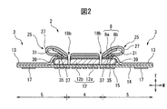
- FIG. 1 to FIG. 2 are diagrams showing a configuration example of an absorbent article 1 (sanitary napkin) according to the present embodiment.
- FIG. 1 is a plan view showing a state where the absorbent article 1 is developed
- FIG. 2 is a cross-sectional view taken along the line II-II in FIG.
- the absorbent article 1 has a longitudinal direction L, a width direction W, and a thickness direction T that are orthogonal to each other, and a main body portion 2 that extends in the longitudinal direction L in plan view, and a substantially central portion of the main body portion 2 in the longitudinal direction L.
- a pair of flap portions 3 and 3 extending to both outer sides in the width direction W.
- the absorbent article 1 has a longitudinal center line CL extending in the longitudinal direction L through the center in the width direction W, and a width direction center line CW extending in the width direction W through the center in the longitudinal direction L of the pair of flap portions 3 and 3. And have. Since the longitudinal direction L, the width direction W, and the thickness direction T of the absorbent article 1 coincide with the longitudinal direction, the width direction, and the thickness direction of each material of the absorbent article 1, the absorbent article 1 and each material thereof However, the longitudinal direction L, the width direction W and the thickness direction T are used in common.
- One and the other in the longitudinal direction L are the front and the rear, respectively, the one and the other in the width direction W are the left and the right, respectively, and one and the other in the thickness direction T are the upper and the lower, respectively.
- the upper side and the lower side of the figure are the front and rear in the longitudinal direction L, respectively, and the left side and the right side are the left and right sides in the width direction W, respectively.
- the front side and the back side are above and below the thickness direction T, respectively.
- the “plan view” means that the absorbent article 1 in a developed state is viewed in the thickness direction T from the upper surface side.
- “Skin side” and “non-skin side” refer to the side that is relatively closer to the skin surface of the wearer and the far side in the thickness direction T when the wearer wears the absorbent article 1, respectively.
- the “in-plane direction” is a direction parallel to the plane including the width direction W and the longitudinal direction L.
- a direction toward the longitudinal center line CL and a direction away from the center line CL are defined as “inside” and “outside” directions in the width direction W, respectively.
- the direction toward the center line CW in the width direction and the direction away from the center line CW are defined as “inside” and “outside” directions in the longitudinal direction L, respectively.
- the main body 2 has a rounded rectangular or racetrack shape extending in the longitudinal direction L in plan view.
- the outer edges of both ends in the longitudinal direction L of the main body 2 have a substantially semicircular or substantially bowl shape.
- the flap portion 3 has a trapezoidal shape, a semicircular shape, or a semielliptical shape. When the flap portion 3 is trapezoidal, the lower bottom extends along the longitudinal direction L and contacts both side edges of the main body portion 2 in the width direction W. When the flap portion 3 is semicircular or semielliptical, the string extends along the longitudinal direction L and touches both side edges of the main body portion 2 in the width direction W.
- the absorbent article 1 includes a top sheet 8 positioned on the skin side, a back sheet 14 positioned on the non-skin side, and an absorbent body 12 positioned between the top sheet 8 and the back sheet 14.
- the top sheet 8 is a liquid permeable sheet.
- the surface sheet 8 include liquid-permeable nonwoven fabrics and woven fabrics, synthetic resin films having liquid-permeable holes, and composite sheets thereof.
- the absorbent article 1 further includes a pair of side sheets 13 and 13 that are joined to both end portions in the width direction W of the topsheet 8 and extend to both outer sides in the width direction W.
- the side sheet 13 is a water repellent sheet.
- the side sheet 13 examples include a nonwoven fabric subjected to water repellent treatment and a synthetic resin film having air permeability.
- the back sheet 14 is a liquid-impermeable sheet. Examples of the back sheet 14 include liquid-impermeable nonwoven fabrics and synthetic resin films, composite sheets of nonwoven fabrics and synthetic resin films, and SMS nonwoven fabrics.
- the absorbent article 1 may further include a breathable exterior sheet on the non-skin side of the back sheet 14.
- the absorbent body 12 is a layer having a rounded rectangular shape, a racetrack shape, or an hourglass shape that is slightly smaller than the main body 2 and has liquid absorption performance and liquid retention performance.
- the absorbent core 12b includes a liquid retaining material and an absorbent polymer.
- the liquid retaining material include water absorbent fibers such as pulp.
- the absorbent polymer include a super absorbent polymer (SAP) that can absorb and retain water.
- the core wrap 12a is a sheet having liquid permeability, and examples thereof include a hydrophilic nonwoven fabric such as a tissue.
- the top sheet 8 has a two-layer structure of an upper layer sheet 8a located on the skin side and a lower layer sheet 8b located on the non-skin side.
- the upper layer sheet 8 a is a so-called surface sheet, and includes a pair of loop portions 25 and 25 at both ends in the width direction W.
- the loop portion 25 is formed by folding both side portions of the upper layer sheet 8a in the width direction W inside the width direction W and on the non-skin side (below the thickness direction T) of the upper layer sheet 8a. Is done.
- the end portions of the folded back side portions of the upper layer sheet 8 a are paired with the pair of side sheets 13, 13 that extend continuously or intermittently along the longitudinal direction L.
- the end portions of the folded back side portions of the upper layer sheet 8a are continuously or intermittently along the longitudinal direction L on the non-skin side surfaces of both side portions in the width direction W of the lower layer sheet 8b.
- a pair of second adhesive portions 37 and 37 are joined to each other by a pair of second adhesive portions 37 and 37 (example: hot melt adhesive).
- the pair of first adhesive portions 35, 35 and the pair of second adhesive portions 37, 37 are inside the pair of end edges 39, 39 of the absorbent body 12 in the width direction W in plan view, and therefore absorb. It overlaps with the body 12.
- the pair of first adhesive portions 35, 35 may be located further inside in the width direction W.
- the lower layer sheet 8b is a liquid-permeable sheet called a so-called second sheet.
- the lower layer sheet 8b is slightly smaller in the width direction W than the upper layer sheet 8a.
- both end edges of the lower layer sheet 8b in the width direction W are the edges of the pair of loop portions 25, 25 in plan view. 27, and substantially overlaps both end edges of the absorbent body 12 in the width direction W.
- a synthetic fiber nonwoven fabric for example, an air-through nonwoven fabric may be mentioned.
- the upper layer sheet 8a may include a flange portion and a groove portion that extend along the longitudinal direction L and are arranged at a predetermined interval in the width direction W.
- the non-skin side surface of the top sheet 8 and the skin side surface of the absorbent body 12 are joined with an adhesive (eg, hot melt adhesive) or the like, and the non-skin side surface of the absorbent body 12
- the back side sheet 14 is bonded to the skin side surface with an adhesive or the like.
- the peripheral edge of the non-skin side surface of the top sheet 8 and the skin side surface of the back sheet 14 are joined together with an adhesive or the like.
- the pair of flap portions 3, 3 the non-skin side surface of each of the pair of side sheets 13, 13 and the outer end portion in the width direction W on the skin side surface of the back sheet 14 are joined with an adhesive or the like.
- the absorbent article 1 further includes an adhesive part 15 and a pair of adhesive parts 17 and 17 arranged on the non-skin side surfaces of the main body part 2 and the pair of flap parts 3 and 3, respectively.
- the adhesive portion 15 is disposed on the non-skin side surface of the back sheet 14 so as to overlap the absorber 12 in a plan view, and continuously extends in the longitudinal direction L and is intermittently arranged in the width direction W, for example.
- the adhesive portion 15 affixes the non-skin side surface of the main body 2 to the skin side surface of the underwear, and the pair of adhesive portions 17 and 17 are below the underwear.
- the skin-side surfaces (the non-skin-side surfaces before folding) of the pair of flap portions 3 and 3 folded back are pasted on the non-skin-side surfaces of the underwear, respectively. Thereby, the absorbent article 1 is fixed to the underwear.
- each pressure-sensitive adhesive a material known in the field of absorbent articles can be used.
- the excretory opening contact area 30 is set in a central region in the width direction W slightly closer to the front in the longitudinal direction L of the main body 2 in plan view.
- the excretion opening contact area 30 is an area that faces or contacts the wearer's excretion opening when the absorbent article 1 is worn.
- region 30 can be suitably set according to the kind and application (example: kind of liquid excrement, wearer's age and sex) of the absorbent article 1.
- the excretion opening contact region 30 is, for example, approximately 1/3 of the entire length of the absorbent body 12 in a substantially central portion of the absorbent body 12 in the longitudinal direction L and slightly forward, and in the width direction W, the absorbent body 12.
- the absorbent article 1 includes a pair of compressed grooves 18 and 18 that are positioned continuously or intermittently on both outer sides in the width direction W and the longitudinal direction L of the excretory opening contact area 30.
- the pressing groove 18 (18a, 18b, 18c, 18d) is located in the left-right outer side of the width direction W in the excretion opening
- the pressing groove 18 is formed by pressing the top sheet 8, the skin side core wrap 12a, and the absorbent core 12b.
- the compressed groove 18 preferably reaches the bottom of the absorbent core 12b.
- the pressing groove 19 is further provided in the front and back of the longitudinal direction L rather than the pressing grooves 18a and 18d, respectively.
- the shape of the pressing grooves 18 and 19 is arbitrary.
- the absorbent article 1 has, in the width direction W, a pair of excretion port corresponding regions 4 that are regions inside the pair of pressing grooves 18 and 18 and a pair of excretion port corresponding regions 4 located on both outer sides. It has the excretion mouth adjacent area
- a pair of boundaries between the excretion opening corresponding area 4 and the pair of excretion opening adjacent areas 5 and 5 are parallel to the longitudinal direction L passing through the outermost edge in the width direction W in each of the pair of pressing grooves 18 and 18 in plan view.
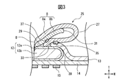
- FIG. 3 is an enlarged partial cross-sectional view of a part of FIG. 2
- FIG. 4 is a perspective view showing a change mode of the absorbent article 1 of FIG. 1
- FIG. 5 is a view of wearing of the absorbent article of FIG. It is a schematic diagram which shows an aspect.
- the pair of loop portions 25, 25 are hollow in which the upper layer sheet 8a is swollen in a loop shape toward both outer sides in the width direction W with positions corresponding to both side edges of the excretory opening corresponding region 4 in the upper layer sheet 8a as a base point B.
- the upper layer sheet 8 a protrudes from the base point B toward the excretory opening adjacent region 5 outside the end edge 39 of the absorber 12 in the width direction W, and is adjacent to the excretion opening.
- An edge 27 is formed in the region 5.
- the upper layer sheet 8a is gently folded back in a loop shape through the end edge 27, and the first adhesive portion 35 is set as the end point inside the end edge 27 and the end edge 39 of the absorber 12.
- a portion of the upper layer sheet 8a ahead of the first adhesive portion 35 is joined to the surface on the absorber 12 side in the thickness direction T of the lower layer sheet 8b by the second adhesive portion 37.
- the distance between the inner edge (base point B) in the width direction W of the loop portion 25 and the end edge 27 is preferably 5 to 38 mm, more preferably 8 to 30 mm, from the viewpoint of securing cushioning properties of the loop portion 25. It is. Such a pair of hollow loop portions 25, 25 can be easily deformed.
- a pair of loop parts 25 and 25 can maintain adhesiveness with a wearer's crotch part, a crevice is formed between each loop part 25 and crotch part, and body fluid leaks from the crevice. The situation of side leakage can be suppressed.
- a pair of loop parts 25 and 25 are arrange
- each of the pair of loop portions 25, 25 has a soft feel, and even if the wearer presses the absorbent article 1 in the width direction W with the thigh portions Q, Q of both legs, the absorbent body 12 It is possible to make it difficult to feel the hardness, and thus to secure the cushioning function more reliably.
- the upper layer sheet 8a (including the pair of loop portions 25, 25) of the absorbent body 12 and the top sheet 8 has a pair of compressed grooves 18 and 18 as fulcrums. 18 and 18 are more likely to rise in the thickness direction (vertical direction). Thereby, adhesiveness with a wearer's crotch part in a pair of loop parts 25 and 25 can be raised more.
- FIG. 6 is a schematic diagram illustrating a configuration example of the manufacturing apparatus 300 for the absorbent article 1.
- the manufacturing apparatus 300 includes a first forming unit 300A to a sixth forming unit 300F.
- the method for manufacturing an absorbent article using the manufacturing apparatus 300 includes first to sixth forming steps.
- 7 to 10 are diagrams schematically illustrating a method for manufacturing the absorbent article 1.
- the manufacturing apparatus 300 relates to conveyance of materials such as sheets and semi-finished products, in the conveyance direction MD, the transverse direction CD orthogonal to the conveyance direction MD and along the conveyance surface, and the vertical direction TD orthogonal to the conveyance direction MD and the transverse direction CD. Have.
- the longitudinal direction, the width direction, and the thickness direction of the material and the semi-finished product are all the same as the transport direction MD, the transverse direction CD, and the vertical direction TD. Accordingly, in the material and the semi-finished product, the transport direction MD, the transverse direction CD, and the vertical direction TD are used for the longitudinal direction, the width direction, and the thickness direction, respectively.
- the first forming unit 300A executes the upper layer positioning step, the upper layer bulk recovery step, the lower layer positioning step, the upper and lower layer bonding application step, the laminating step, the folding positioning step, and the folding step.
- the upper layer continuous sheet P12a for the upper layer sheet unwound from the first material roll WR1 is positioned with reference to the center of the transverse direction CD in the upper layer continuous sheet P12a while being transported in the transport direction MD.
- the upper layer continuous sheet P12a is positioned.
- the position in the positioning step in the manufacturing apparatus 300 is identified by, for example, a method of detecting the position of the edge of the sheet by a detection device such as an image sensor, and the center position is derived from the detected position of both ends of the sheet. It can be performed by a method or the like.
- the upper layer continuous sheet P12a positioned at an appropriate position is heat treated by the first heat treatment apparatus 251 while being transported in the transport direction MD, and the bulk continuous sheet P12b is formed. Is done.
- the material of the upper-layer continuous sheet P12a is a continuous sheet that can recover its bulk, and is the material of the upper-layer sheet 8a.
- fibers of a PET / HDPE core / sheath structure are used.
- One surface of the upper continuous sheet P12a is a net surface, and the other surface is an anti-net surface.
- the lower layer continuous sheet P13a for the lower layer sheet unwound from the second material roll WR2 is positioned with reference to the center of the transverse direction CD in the lower layer continuous sheet P13a.
- the lower layer continuous sheet P13a is positioned so that the center of the transverse direction CD in the lower layer continuous sheet P13a coincides with the conveyance center.
- the material of the lower layer continuous sheet P13a is a continuous sheet capable of recovering bulk, and is the material of the lower layer sheet 8b.
- a fiber having a PET / HDPE core / sheath structure is used.
- One surface of the lower layer continuous sheet P13a is an anti-net surface, and the other surface is a net surface.
- the upper layer continuous sheet P12a and the lower layer continuous sheet P13a are non-woven fabrics, and are manufactured by stacking (depositing) fibers on a fiber support such as a net. These sheets have a net surface that is in contact with the fiber support (net) at the time of manufacture, and an anti-net surface opposite to the net surface. In the net surface side portions of these sheets, the fiber density of the constituent fibers is high and the rigidity is high as compared with the anti net surface side portion. Further, the upper layer bulk recovery step can be regarded as a top sheet bulk recovery step because the top sheet 8 is bulk recovered.
- the lower layer continuous sheet P13a is supplied to the application device 301.
- the lower layer continuous sheet P13a is coated with an adhesive (eg, hot melt adhesive) in a predetermined pattern on one surface.
- an adhesive eg, hot melt adhesive
- the predetermined pattern is a stripe pattern having a predetermined width extending along the transport direction and arranged at a predetermined interval in the transverse direction.
- the upper layer continuous sheet P12b is transported in the transport direction MD, and the center LTS1 of the transverse layer CD in the upper layer continuous sheet P12b is used as a reference. Is positioned.
- the lower layer continuous sheet P13b is positioned with reference to the center LTS2 in the transverse direction CD of the lower layer continuous sheet P13b while being conveyed in the conveyance direction MD.
- the upper-layer continuous sheet P12b and the lower-layer continuous sheet P13b are positioned so that the conveyance center BL0 matches the center LTS1 and the center LTS2.
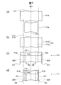
- the upper layer continuous sheet P12b and the lower layer continuous sheet P13b are supplied and sandwiched in a facing area between the outer peripheral surface of the bonding roll 252 and the outer peripheral surface of the bonding roll 256. Thereby, the upper layer continuous sheet P12b and the lower layer continuous sheet P13b are joined. That is, as shown in FIG.7 (b) and FIG.8 (b), the continuous surface sheet P10 which is a laminated body of the upper layer continuous sheet P12b and the lower layer continuous sheet P13b is formed.
- the upper continuous sheet P12b and the lower continuous sheet P13b are brought into close contact with each other.
- the anti-net surfaces of the upper continuous sheet P12b and the lower continuous sheet P13b are joined.
- the anti-net surface has a low fiber density and is easy to fluff. Therefore, the fluffy constituent fibers come into contact with each other, and the contact between both sheets becomes stronger.
- the state of the fiber recovered by cooling can be fixed, and can be maintained in the subsequent steps.
- the upper layer bulk recovery step is not limited to the above example, and a known bulk recovery method as disclosed in, for example, Japanese Patent Application Laid-Open No. 2004-137655 may be used.
- the continuous surface sheet P10 is positioned with reference to the center LTS1 in the transverse direction CD of the continuous surface sheet P10 while being conveyed in the conveyance direction MD. That is, the continuous surface sheet P10 is positioned so that the conveyance center BL0 and the center LTS1 coincide.
- the continuous surface sheet P10 positioned with reference to the center LTS1 is supplied to the coating apparatus 302 while being transported in the transport direction MD.
- the continuous surface sheet P10 extends in the conveyance direction MD and is located in the center part P10C located in the center of the transverse direction CD, and extends in the conveyance direction MD and is located on both outer sides of the transverse direction CD of the center part P10C.
- a pair of side portions P10S and P10S are shown in FIG.7 (c) and FIG.8 (c), in the surface below the up-down direction TD of the continuous surface sheet P10, a pair of inner side edge part INS of the transverse direction CD in a pair of side part P10S and P10S.
- An adhesive for example, hot melt adhesive
- a pair of 2nd adhesion parts 302X and 302X are formed in one side of continuous surface sheet P10.
- the pair of second adhesive portions 302X and 302X are lower than the pair of outer end portions OTS and OTS in the transverse direction CD in the pair of side portions P10S and P10S on the lower surface in the vertical direction TD of the continuous surface sheet P10. If it is inside, it may be formed outside the pair of inner ends INS and INS.
- the continuous surface sheet P10 is supplied to the loop forming device 259 while being conveyed in the conveyance direction MD. Then, as shown in FIGS. 7D and 8D, the pair of side portions P10S and P10S are folded back in a loop shape toward the central portion P10C by the loop forming device 259, and the pair of side portions P10S.
- the pair of outer end portions OTS, OTS in the transverse direction CD of P10S are overlapped with the pair of inner end portions INS, INS.
- the pair of outer end portions OTS, OTS of the pair of side portions P10S, P10S and the pair of inner end portions INS, INS are joined via the pair of second adhesive portions 302X, 302X.
- the continuous surface sheet P11 in which a pair of loop portions 225 and 225 are formed on both outer sides of the central portion P10C is formed.
- both end edges of the transverse CD cannot be used as a positioning reference.
- a pair of loop portions 225 and 225 extension portions are formed as both end portions in the transverse direction CD.
- both end edges in the transverse direction CD of the continuous surface sheet P10 that cause the variation of the dimension (width) are folded back inward so that they are not end edges.
- the edge 227 in the transverse direction CD of the loop portion 225 is substantially the both end edges in the transverse direction CD of the continuous surface sheet P11.
- the dimension (width) in the transverse direction CD becomes a constant size, and there is no fluctuation. Further, the substantial end edges of the continuous surface sheet P11 in the transverse direction CD become the folded portions of the loop portions 225 and have a thick structure in which the two upper and lower sheets are stacked. Can be detected. As a result, substantially both end edges in the transverse direction CD of the continuous surface sheet P11 including the pair of loop portions 225 and 225 (a pair of end edges 227 and 227 on both outer sides of the pair of loop portions 225 and 225 in the transverse direction CD). ) Can be used as a reference for positioning in subsequent manufacturing steps (example: step of joining absorbent bodies, step of forming compressed grooves).
- the continuous surface sheet is tensioned in the conveyance direction MD, and thus the pair of loop portions 225 and 225 have a flat loop shape in the vertical direction TD. There is no problem in detecting both ends.
- the second forming unit 300B executes a cutting step, a first positioning step, and a coating step.
- the continuous side sheet SS for the side sheet that has been rewound from the third material roll WR3 is positioned with reference to the center of the transverse direction CD in the continuous side sheet SS while being conveyed in the conveyance direction MD. . Specifically, the positioning is performed so that the center of the transverse direction CD in the continuous side sheet SS coincides with the conveyance center. Then, the continuous side sheet SS is cut into two equal parts in the width direction W along the transport direction MD at the center position in the transverse direction CD in the continuous side sheet SS by the cutting device 260, and mutually in the width direction W. A pair of adjacent continuous side sheets SSa and SSb are formed.
- the pair of continuous side sheets SSa and SSb are conveyed in the conveyance direction MD as shown in FIG. 9A and FIG. , SSb is positioned with reference to a pair of inner end edges LTS3, LTS3 facing each other in the transverse direction CD. Specifically, the pair of continuous side sheets SSa, SSb are separated from the pair of inner end edges LTS3, LTS3 by a first distance d1 toward the outer end edge of each continuous side sheet SSa, SSb. Positioning is performed so that the side sheet areas AS and AS are located.
- the pair of side sheet areas AS and AS are areas in which a pair of first adhesive portions 303X and 303X (corresponding to the pair of first adhesive portions 35 and 35) described later is formed.
- the first distance d1 is a distance provided in advance so that the adhesive does not protrude when the adhesive of the first adhesive portion 303X described later is applied.
- the positioning of the pair of continuous side sheets SSa and SSb with reference to the pair of inner end edges LTS3 and LTS3 can be performed as follows. From the viewpoint of the substantial size in the width direction W of the surface sheet 8 of the absorbent article 1, a pair of first adhesive portions 303X and 303X that join the pair of continuous side sheets SSa and SSb and the continuous surface sheet P11. A distance D1 between them is set.
- the pair of first end edges LTS3 and LTS3 and the pair of first end portions LTS3 and LTS3 A first distance d1 between each of the first adhesive portions 303X and 303X is set. Accordingly, the pair of inner end edges LTS3, LTS3 are positioned at a distance of (D1 / 2) outside the width direction W with respect to the transport center BL0.
- the pair of side sheet regions AS and AS which are regions where the pair of first adhesive portions 303X and 303X are to be formed, are formed from the pair of inner end edges LTS3 and LTS3 to the outside in the width direction W. It is located at the distance d1.
- a pair of continuous side sheets SSa and SSb are supplied to the coating devices 303a and 303b, respectively.
- the pair of continuous side sheets SSa and SSb is formed on the one surface of the pair of side sheet areas AS and AS, with a pair of first adhesive portions 303X and 303X. (Example: hot melt adhesive) is applied in a predetermined pattern. Therefore, a pair of continuous side sheets SSa and SSb coated with an adhesive are formed.
- the third forming unit 300C executes the second positioning step and the joining step.
- the continuous surface sheet P11 is transported in the transport direction MD as shown in FIGS. 9C and 10C, and the center LTS1 of the transverse surface CD in the continuous surface sheet P11 is used as a reference. Is positioned. Specifically, the continuous surface sheet P11 is separated from the center LTS1 in the transverse direction CD by a second distance d2 on both outer sides, and is greater than a third distance d3 that is larger than the first distance d1 on the inner sides from both edges 227 and 227. Positioning is performed so that the pair of top sheet areas AT and AT are positioned at positions apart from each other. The pair of top sheet areas AT and AT are areas where the pair of first adhesive portions 303X and 303X are joined.
- the third distance d3 is a distance that is larger than the distance that is preliminarily provided so that the adhesive does not protrude, such as the first distance d1, and that the positive enemy extends outward in the width direction W.
- the pair of continuous side sheets SSa and SSb positioned in the first positioning process and the continuous surface sheet P11 positioned in the second positioning process are conveyed in the conveyance direction MD, It is supplied to the joining device 261 of the third forming unit 300C. Then, the pair of continuous side sheets SSa, SSb and the continuous surface sheet P11 are sandwiched and bonded between the pair of bonding rolls 261a, 261b of the bonding apparatus 261. Thereby, as shown in FIG. 9 (d) and FIG.
- the continuous topsheet P2 is formed by joining AS to the pair of first adhesive portions 303X and 303X.
- the continuous surface sheet P2 has a pair of loop portions 225 and 225 extending outward in the width direction W from the pair of first adhesive portions 303X and 303X, that is, a pair of extending portions (225 and 225). Is done.
- the pair of first adhesive portions 303X and 303X is applied to the pair of side sheet regions AS and AS (a pair of continuous side sheets SSa and SSb) by a coating process before the bonding process.
- the pair of first adhesive portions 303X and 303X may be formed in the pair of surface sheet regions AT and AT (continuous surface sheet P11). That is, the pair of first adhesive portions 303X and 303X are separated from each other by the second distance d2 from the center of the transverse surface CD in the continuous surface sheet P11 by the other application step before the joining step, and both end edges 227 and 227 are placed.
- a pair of topsheet regions AT and AT separated from each other by a third distance d3 larger than the first distance d1 may be formed. Therefore, when the pair of continuous side sheets SSa, SSb and the continuous surface sheet P11 are joined, the coating process is performed from the pair of inner side edges LTS3, LTS3 in the pair of continuous side sheets SSa, SSb.
- the first positioning step so that the pair of topsheet regions AT and AT separated by a third distance d3 or more greater than the first distance d1 is joined via the pair of first adhesive portions 303X and 303X. Transported to the pair of side sheet areas AS, AS or the pair of top sheet areas AT, AT positioned in the second positioning step The pair along the direction MD first adhesive portion 303X, to form a 303X.
- the inner end INS of the side portion P10S serving as the base point of each loop portion 225 and the outer end portion OTS of the side portion P10S serving as the end point are joined with an adhesive.
- the loop shape of the loop portion 225 can be fixed and stabilized.
- the substantial both-ends 227 and 227 of the continuous surface sheet P2 in the transverse direction CD can be formed more stably as a positioning reference.
- both end portions of the lower continuous sheet P13b of the continuous surface sheet P10 are on the inner side than both end portions of the upper continuous sheet P12b of the continuous surface sheet P10.
- the upper layer continuous sheet P12b comprises each of a pair of loop part 225,225.
- the lower layer continuous sheet P13b extends to a position in the middle of each of the pair of loop portions 225 and 225, that is, to a position inside the end edge 227. Therefore, in the folding step, the portion to be folded mainly is one upper layer continuous sheet P12b, so that the continuous surface sheet P10 can be easily folded and the loop portion 225 can be formed stably.
- the pair of outer end portions OTS, OTS of the pair of side portions P10S, P10S and the pair of continuous side sheets SSa, SSb are stabilized via the pair of first adhesive portions 303X, 303X. Therefore, it is possible to suppress the occurrence of a problem in joining.
- the absorbent article 1 in each loop, the main part that becomes a flap-shaped member extending outward in the width direction is two sheets of an upper layer continuous sheet and a lower layer continuous sheet, so that some rigidity is provided to the loop part. It can be applied to stabilize the shape. Even if the thighs of both legs are sandwiched in the width direction, an elastic configuration can be maintained.
- the bulk-recoverable continuous sheet is bulk-recovered into the upper-layer continuous sheet P12b, so that the density of the P12b constituent fibers of the upper-layer continuous sheet is reduced overall, Therefore, flexibility can be increased.
- the pair of side portions P10S and P10S of the continuous surface sheet P10 can be easily folded, and the pair of loop portions 225 and 225 can be stably formed.
- the net surface of the continuous surface sheet P10 is configured to be an outer surface of each of the pair of loop portions 225 and 225. Accordingly, when the side portion P10S of the continuous surface sheet P10 is folded in the folding step, the inner surface of the loop portion 225 having a high curvature is an anti-net surface having a low rigidity (easy to bend), and the outer portion of the loop portion 225 having a low curvature is provided.
- the surface can be a net surface with high rigidity (hard to bend). Accordingly, in the folding step, the pair of side portions P10S of the continuous surface sheet P10 can be folded more smoothly, and the pair of loop portions 225 and 225 can be stably formed.
- the pair of second adhesive portions 302X and 302X is formed of a pair of first adhesive portions 303X when the continuous surface sheet P11 and the pair of continuous side sheets SSa and SSb are joined. , 303X, in the transverse direction CD of the continuous surface sheet P11 in a plan view, and at a position on the continuous surface sheet P11. Accordingly, the pair of loop portions 225 and 225 opposite to the pair of second adhesive portions 302X and 302X are raised in the vertical direction TD (thickness direction T) with the pair of first adhesive portions 303X and 303X as fulcrums. Easy structure.
- the fourth forming unit 300D performs the absorber bonding application step, the absorber bonding positioning step, and the absorber bonding step.
- the continuous surface sheet P2 is supplied to the coating apparatus 304. And the continuous surface sheet P2 is apply
- an adhesive example: hot melt adhesive
- the continuous surface sheet P2 is conveyed in the conveyance direction MD while the pair of edge portions 227 and 227 on both outer sides in the transverse direction CD in the pair of loop portions 225 and 225 is used as a reference. Positioned. Specifically, the pair of end edges 227 and 227 of the pair of loop portions 225 and 225 in the continuous surface sheet P2 are positioned so as to be equidistant from both sides of the transverse direction CD with respect to the transport center BL0. (Fourth positioning step).
- the absorber P3 (absorber 12) is positioned with reference to the center in the transverse direction CD while being transported in the transport direction MD. Specifically, the center of the absorbent body P3 in the transverse direction CD is positioned so as to overlap the transport center BL0.
- the continuous surface sheet P2 and the absorbent body P3 arranged in the transport direction MD at a predetermined interval are supplied to the joining device 261 while being transported in the transport direction MD.
- the continuous surface sheet P2 and the absorber P3 are clamped between a pair of joining rolls 261a and 261b of the joining apparatus 261, and are joined.
- the positions of both ends of the absorbent body 12 in the transverse direction CD overlap with the inner distance of the transverse direction CD from the pair of edges 227 and 227 of the pair of loop portions 225 and 225 in the continuous surface sheet P2.
- the semi-finished product P4 by which the continuous surface sheet P2 and the absorber P3 were laminated
- the continuous surface sheet P2 and the absorber P3 are laminated and bonded so that the pair of first adhesive portions 303X and 303X overlap the absorber P3 in plan view.
- the conveyance center BL0 is located at a position equidistant from the pair of edges 227 and 227 of the pair of loop portions 225 and 225 in the continuous surface sheet P2 to the inside of the transverse direction CD.
- the continuous surface sheet P2 is positioned so that the distance from the transport center BL0 to each of the pair of edges 227, 227 is equal, and the transverse CD of the transport center BL0 and the absorbent body P3 in the transverse direction CD.
- the absorber P3 is positioned so as to overlap with the center. Therefore, the distance between the edge 39 of the absorbent body P3 and the edge 227 of the loop portion 225 of the continuous surface sheet P2 can be the same on both sides in the transverse direction CD. Thereby, the size of the loop portion 225 extending outward from the end edge 39 of the absorbent body P3 in the transverse direction CD can be made the same on both sides of the absorbent body P3 in a plan view.
- the continuous surface sheet P2 and the absorbent body P3 are joined so that the first adhesive portion 303X overlaps the absorbent body 12 in plan view.
- the position of the first adhesive portion 303X is on the absorber 12.
- the first adhesive portion 303X does not overlap the absorber P3 in plan view, and there is no absorber P3 below the first adhesive portion 303X, so the continuous surface is mostly located on the absorber P3.
- the pair of loop portions 225 and 225 can be stably formed, and the functions of the pair of loop portions 25 and 25 in the absorbent article 1 can be effectively exhibited.
- the fifth forming unit 300E executes a pressing groove forming positioning step and a pressing groove forming step.
- the semi-finished product P4 that is a laminated member of the continuous surface sheet P2 and the absorbent body P3 is conveyed in the conveying direction MD, and the transverse CD in the pair of loop portions 225 and 225 is used. Positioning is performed with reference to the pair of outer edges 227 and 227 on both outer sides. Specifically, the pair of edges 227 and 227 of the pair of loop portions 225 and 225 in the semi-finished product P4 are positioned at equal distance positions on both outer sides in the transverse direction CD with respect to the transport center BL0.
- the semi-finished product P4 is supplied to the pressing device 280 while being transported in the transport direction MD.
- an embossing roll 280a having a convex portion for pressing on the outer peripheral surface and an anvil roll 280b are disposed facing each other.
- the semi-finished product P5 is pinched between the embossing roll 280a and the anvil roll 280b, and is squeezed.
- a pair of squeezing grooves 18 and 18 (/ 19) extending in the transport direction MD at equal distances from the pair of end edges 227 and 227 of the pair of loop portions 225 and 225 in the semi-finished product P4 to the inside of the transverse direction CD. 19) is formed. That is, the semi-finished product P5 which is the semi-finished product P4 in which the pressing grooves 18, 18 (/ 19, 19) are formed is formed.
- the pair of end portions 227 and 227 of the pair of loop portions 225 and 225 are positioned with reference to the pair of end portions 227 of the pair of loop portions 225 and 225.
- a pair of squeezing grooves are formed at equal distances from 227 to the inside.
- the absorbent body 12 and the top sheet 8 are on the outer sides of the pair of compressed grooves 18, 18 with the pair of compressed grooves 18, 18 as fulcrums.
- the sixth forming unit 300F performs the back surface bonding step and other steps.
- the continuous back surface sheet BS for the back surface sheet is supplied from the roll WR5 to the joining device 290 while being transported in the transport direction MD.
- An adhesive for example, hot melt adhesive
- the semi-finished product P5 is supplied to the bonding apparatus 290 while being transported in the transport direction MD.
- the continuous back sheet BS and the semi-finished product P6 are sandwiched and joined between the pair of joining rolls 290a and 290b of the joining device 290. Thereby, the semi-finished product P6 in which the continuous back sheet BS and the semi-finished product P5 are laminated in the vertical direction TD is formed.
- the release sheet CT with the adhesive is joined to the semi-finished product P7 (adhesive portions 15 and 17), the surrounding portions are cut, separated into the shape of the absorbent article 1, and the absorbent article 1 Is formed.
- the absorbent article 1 is packaged in a packaging process.
- the absorbent article 1 is manufactured.
- the extension part is formed in a loop shape in the absorbent article 1 manufactured using the continuous surface sheet P2 (the loop part 25), the extension part is a single sheet. Compared with the case where it is comprised by, an extending part can be made more elastic and flexible. Thereby, since a pair of extension part (a pair of loop part 25) can maintain the adhesiveness with a wearer's crotch part more, it can improve the leak prevention property of absorptive goods, and body adaptability more.
- a pair of second side sheets SSa, SSb arranged at appropriate positions by positioning is used as a reference with respect to the inner end edges LTS3, LTS3 of the pair of continuous side sheets SSa, SSb, or with reference to the center LTS1 of the continuous surface sheet P11.
- One adhesive portion 303X, 303X can be formed at an appropriate position (a pair of side sheet regions AS, AS or a pair of surface sheet regions AT, AT) of the pair of continuous side sheets SSa, SSb or the continuous surface sheet P11.
- the pair of side sheet areas AS and AS and the pair of topsheet areas AT disposed at appropriate positions via the pair of first adhesive portions 303X and 303X formed at appropriate positions.
- AT can be joined.
- a pair of extension part (225, 225) extended on both outer sides rather than a pair of 1st adhesion part 303X, 303X can be formed.
- the pair of first adhesive portions 303X, 303X can be combined. It can be placed at an appropriate position.
- the pair of first adhesive portions 303X and 303X protrudes inward from the pair of inner side edges LTS3 and LTS3 of the pair of continuous side sheets SSa and SSb, or both end edges 227 and 227 of the continuous surface sheet P11, That is, it is possible to prevent the pair of extending portions (225, 225) from being protruded by being shifted outward from the end edges 227, 227.
- the overlapping area of both sheets is small, and even if the width of both sheets fluctuates, the influence of fluctuations in the position of the edges of both sheets is alleviated, and the adhesive protrudes from the edge of either sheet. Can be suppressed.
- the absorbent article 1 when forming the absorbent article 1 having a pair of extending portions (225, 225; flap-shaped members) extending outward in the transverse direction CD (width direction) of the continuous surface sheet P11 (center sheet).
- a problem in bonding occurs. This can be suppressed.
- the manufactured absorbent article 1 can improve the leakage prevention property and body compatibility of the absorbent article.
- the top sheet 8 includes a pair of loop portions 25 and 25 on both sides, but the present invention is not limited to this example.
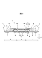
- FIG. 11 is a cross-sectional view illustrating another configuration example of the absorbent article according to the embodiment.
- a pair of extending portions 25, 25 formed of a single sheet are formed on both sides of the top sheet 8 instead of each of the pair of loop portions.
- the manufacturing method of this absorbent article can be called the manufacturing method which does not implement a folding
- the absorbent article of the present invention is not limited to the above-described embodiments, and can be appropriately combined and changed without departing from the object and spirit of the present invention.
Landscapes
- Health & Medical Sciences (AREA)
- Epidemiology (AREA)
- Engineering & Computer Science (AREA)
- Biomedical Technology (AREA)
- Heart & Thoracic Surgery (AREA)
- Vascular Medicine (AREA)
- Life Sciences & Earth Sciences (AREA)
- Animal Behavior & Ethology (AREA)
- General Health & Medical Sciences (AREA)
- Public Health (AREA)
- Veterinary Medicine (AREA)
- Absorbent Articles And Supports Therefor (AREA)
Abstract
表面シートの両側にフラップ部材を有する吸収性物品の製造において、表面シートの端部と一対のサイドシートの端部との接合上の問題を抑制する。製造方法は、連続サイドシート(SSa、SSb)の向かい合う内側端縁(LTS3、LTS3)を基準に、連続サイドシートを位置決めする工程と、連続表面シート(P11)の中心(LTS1)を基準に、連続表面シートを位置決めする工程と、連続サイドシートと連続表面シートとの接合時、連続サイドシートのサイドシート領域(AS、AS)と、連続表面シートの表面シート領域(AT、AT)とが、の第1の接着部(303X、303X)を介して接合されるように、サイドシート領域又は表面シート領域に第1の接着部を形成する工程と、表面シート領域とサイドシート領域とを第1の接着部で接合し、連続表面シートにおける第1の接着部よりも両外側に延出する延出部(225、225)を形成する工程と、を備える。
Description
本発明は、吸収性物品の製造方法に関する。
吸収性物品の製造方法では、複数のシートを全体的又は部分的に積層する工程を用いる場合がある。その工程を含む吸収性物品の製造方法として特許文献1の吸収性物品の製造方法が挙げられる。この製造方法では、一枚の原反シートを連続的に搬送しながらその流れ方向に沿って切断して4本以上の分割シートを造る分割工程、及び、その分割シートのうちのその原反シートの側縁であった端縁を含む外側シートと、その原反シートの側縁であった端縁を含まない内側シートと、を組み合わせて積層一体化する一体化工程を含む。
積層一体化工程では、幅方向において、内側シート及び外側シートの位置関係を以下の方法で調整する。まず、内側シートについては、鏡板から内側シートの両端縁それぞれまでの距離の平均値(=内側シートの中心位置)が、予め設定された中心位置の基準値と同じになるように、内側シートの搬送軌道を修正する。一方、外側シートについては、鏡板から外側シートの両端縁それぞれまでの距離の平均値(=外側シートの中心位置)が、上述された予め設定された中心位置の基準値と同じになるように、外側シートの搬送軌道を修正する。そして、内側シートと外側シートとを、中心位置が概ね重なった状態で全面的に重ね合わせる。このように、特許文献1では、幅方向におけるシートの位置関係の調整を、シートの両端縁の位置から求めた中心位置と、予め設定された位置とを合致させることで行っている。すなわち、中心基準ということができる。
一方、吸収性物品は、着用者の排泄物の漏れを防止しつつ、着用者の股間部に接触しながら長時間着用される。そのため、吸収性物品には、漏れを防止する特性の他に、身体に良好かつ快適に適合する特性が求められる。そのような漏れ防止性や身体適合性に関連する吸収性物品としては、特許文献2の吸収性物品が挙げられる。この吸収性物品は、着用者の股間部に対応する位置に弾性サイドフラップを有しており、使用時の身体に対する装着性を高め、横漏れを改善できる、とされている。
積層一体化工程では、幅方向において、内側シート及び外側シートの位置関係を以下の方法で調整する。まず、内側シートについては、鏡板から内側シートの両端縁それぞれまでの距離の平均値(=内側シートの中心位置)が、予め設定された中心位置の基準値と同じになるように、内側シートの搬送軌道を修正する。一方、外側シートについては、鏡板から外側シートの両端縁それぞれまでの距離の平均値(=外側シートの中心位置)が、上述された予め設定された中心位置の基準値と同じになるように、外側シートの搬送軌道を修正する。そして、内側シートと外側シートとを、中心位置が概ね重なった状態で全面的に重ね合わせる。このように、特許文献1では、幅方向におけるシートの位置関係の調整を、シートの両端縁の位置から求めた中心位置と、予め設定された位置とを合致させることで行っている。すなわち、中心基準ということができる。
一方、吸収性物品は、着用者の排泄物の漏れを防止しつつ、着用者の股間部に接触しながら長時間着用される。そのため、吸収性物品には、漏れを防止する特性の他に、身体に良好かつ快適に適合する特性が求められる。そのような漏れ防止性や身体適合性に関連する吸収性物品としては、特許文献2の吸収性物品が挙げられる。この吸収性物品は、着用者の股間部に対応する位置に弾性サイドフラップを有しており、使用時の身体に対する装着性を高め、横漏れを改善できる、とされている。
ところで、資材ロールから供給されるシートの幅は常に同じ値であることが好ましいが、一般的には、シートの幅は所定の許容範囲内で長手方向に沿って連続的に増加したり減少したりする。したがって、中心基準でシートを搬送すると、シートの幅の増減に伴い、幅方向のシートの両端縁の位置は搬送方向に沿って連続的に変動することになる。このような場合、特許文献1のように、二枚のシートを全面的に互いに重ね合わせる場合には、シート幅の変動はそれほど問題にはならない。しかし、例えば、搬送方向に沿って中心基準で搬送される一枚のシート(以下、「中央シート」と記す。)の横断方向の両側の端部に、中心基準で搬送される横断方向に隣り合う一対のシート(以下、「一対の側部シート」と記す。)の各々の一方の端部を接着剤で接合する場合、以下のような問題が生じる。接合箇所は、中央シートの端縁に近い部分と、各側部シートの端縁に近い部分になるので、中央シートと側部シートとが重なる領域が小さい。そのため、少なくとも一方のシートの端縁の位置が変動することにより、いずれかのシートの端縁から接着剤がはみ出すおそれがある。そうなると、接合すべき箇所の接合が不十分だったり、不要な箇所に接合が形成されたり、接着剤が肌面側の面に露出したりするなどの接合上の問題が生じるおそれがある。その場合、吸収性物品の着用者が違和感を覚えるなどのおそれがあるため、そのような吸収性物品は不良品として処理しなければならない。特に、吸収性物品の漏れ防止性や身体適合性を高めるべく、幅方向の外側に延出する新規なフラップ状の部材を有する吸収性物品を形成するとき、吸収性物品を構成する部材同士の接合において、その接合上の問題の影響は顕著である。
本発明の目的は、中央シートの幅方向の外側に延出するフラップ状の部材を有する吸収性物品を製造する場合において、搬送方向に搬送される中央シート及び一対の側部シートの横断方向の端部同士を接合するとき、接合上の問題が生じることを抑制することが可能な吸収性物品の製造方法を提供する。
本発明の吸収性物品の製造方法は次のとおりである。(1)表面シートと、前記表面シートにおける非肌側の幅方向の両端部に一端部が重なるように接合された一対のサイドシートと、を含む吸収性物品の製造方法であって、搬送方向に延び、横断方向に隣り合う、前記一対のサイドシート用の一対の連続サイドシートを、前記搬送方向に搬送しつつ、前記一対の連続サイドシートにおける前記横断方向の互いに向かい合う一対の内側端縁を基準に位置決めする第1の位置決め工程と、前記搬送方向に延びる前記表面シート用の連続表面シートを、前記搬送方向に搬送しつつ、前記連続表面シートにおける前記横断方向の中心を基準に位置決めする第2の位置決め工程と、前記一対の連続サイドシートと前記連続表面シートとが接合されるときに、前記一対の連続サイドシートにおける前記一対の内側端縁から各連続サイドシートの外側端縁に向かって第1の距離離れた一対のサイドシート領域と、前記連続表面シートにおける前記横断方向の中心から両外側に第2の距離離れかつ両端縁から内側に前記第1の距離より大きい第3の距離以上離れた一対の表面シート領域とが、一対の第1の接着部を介して接合されるように、前記第1の位置決め工程で位置決めされた前記一対のサイドシート領域又は前記第2の位置決め工程で位置決めされた前記一対の表面シート領域に、前記搬送方向に沿って前記一対の第1の接着部を形成する塗布工程と、前記連続表面シートにおける前記一対の表面シート領域と、前記一対の連続サイドシートにおける前記一対のサイドシート領域とを前記一対の第1の接着部を介して接合することで、前記連続表面シートにおける前記一対の第1の接着部よりも両外側に延出する、一対の延出部を形成する接合工程と、を備える、吸収性物品の製造方法。
本吸収性物品の製造方法において、第1の位置決め工程では、横断方向において、一対の連続サイドシートを幅の変動に影響されない内側端縁で位置決めしている。更に、第2の位置決め工程では、横断方向において、連続表面シートを幅の変動に影響されない中心で基準に位置決めしている。そのため、塗布工程において、位置決めにより適切な位置に配置された一対の連続サイドシートの内側端縁又は連続表面シートの中心を基準にして、一対の第1の接着部を一対の連続サイドシート又は連続表面シートの適切な位置(一対のサイドシート領域又は一対の表面シート領域)に形成できる。その結果、接合工程において、位置決めにより適正な位置に形成された一対の第1の接着部を介して、位置決めにより適切な位置に配置された一対のサイドシート領域と一対の表面シート領域とを接合できる。そして、連続表面シートにおいて、一対の第1の接着部よりも両外側に延出する一対の延出部を形成することができる。このように、一対の連続サイドシートの内側端縁での位置決めと連続表面シートの中心での位置決めとを組み合わせることで、一対の第1の接着部を適正な位置に配置できる。そして、一対の第1の接着部が一対の連続サイドシートの一対の内側端縁から内側にずれてはみ出すことや、連続表面シートの両端縁、すなわち一対の延出部の外側端縁から外側にずれて、はみ出すことを防止できる。それにより、両シートが重なる領域が小さく、両シートの幅が変動しても、両シートの端縁の位置の変動の影響が緩和され、いずれかのシートの端縁から接着剤がはみ出すことを抑制できる。
すなわち、連続表面シート(中央シート)の横断方向(幅方向)の外側に延出する一対の延出部(フラップ状の部材)を有する吸収性物品を形成する場合、搬送方向に搬送される連続表面シート(中央シート)及び一対の連続サイドシート(側部シート)の横断方向の端部同士を接合するとき、接合上の問題が生じることを抑制できる。一方、製造された吸収性物品では、延出部は、横断方向において、表面シートにおける両端縁から内側に第3の距離以上の幅を有する部分である。第3の距離は、接着剤を塗布するときにはみ出しや誤差を吸収するために設けられる距離(例示:第1の距離)よりも大きく設定される。したがって、吸収性物品の着用時に、一対の延出部は吸収性物品の幅方向の両外側に延出する。その場合、吸収体が着用者の両脚の大腿部で幅方向に挟まれて、着用者の股部の形状に沿って変形するとき、一対の延出部も、同様に吸収体の変形に追従して容易に変形できる。それにより一対の延出部は、着用者の股部との密着性を維持できるので、吸収性物品の漏れ防止性や身体適合性を高めることができる。
すなわち、連続表面シート(中央シート)の横断方向(幅方向)の外側に延出する一対の延出部(フラップ状の部材)を有する吸収性物品を形成する場合、搬送方向に搬送される連続表面シート(中央シート)及び一対の連続サイドシート(側部シート)の横断方向の端部同士を接合するとき、接合上の問題が生じることを抑制できる。一方、製造された吸収性物品では、延出部は、横断方向において、表面シートにおける両端縁から内側に第3の距離以上の幅を有する部分である。第3の距離は、接着剤を塗布するときにはみ出しや誤差を吸収するために設けられる距離(例示:第1の距離)よりも大きく設定される。したがって、吸収性物品の着用時に、一対の延出部は吸収性物品の幅方向の両外側に延出する。その場合、吸収体が着用者の両脚の大腿部で幅方向に挟まれて、着用者の股部の形状に沿って変形するとき、一対の延出部も、同様に吸収体の変形に追従して容易に変形できる。それにより一対の延出部は、着用者の股部との密着性を維持できるので、吸収性物品の漏れ防止性や身体適合性を高めることができる。
本発明の吸収性物品の製造方法は、(2)前記連続表面シートは、前記搬送方向に延在し、前記横断方向の中央に位置する中央部と、前記中央部の両外側に位置する一対の側部と、を含み、前記連続表面シートを、前記搬送方向に搬送しつつ、前記連続表面シートの前記横断方向の中心を基準に位置決めする折り返し用位置決め工程と、前記横断方向において、前記一対の側部を、前記中央部に向かってループ状に折り返して、前記一対の側部の一対の外側端部を少なくとも前記一対の側部の一対の内側端部と重ねることにより、前記中央部の両外側に一対のループ部を形成する折り返し工程と、を更に備え、前記接合工程は、前記横断方向において、前記一対の側部の前記一対の外側端部を、前記一対の表面シート領域として、前記一対の連続サイドシートの前記一対のサイドシート領域に、前記一対の第1の接着部を介して接合して、前記一対のループ部を前記一対の延出部として形成する工程を含む、上記(1)に記載の吸収性物品の製造方法、であってもよい。
連続表面シートでは、横断方向の寸法(幅)が変動するために、横断方向の両端縁を位置決めの基準にはできない。そこで、本製造方法では、連続表面シートの横断方向の両端部となる一対の延出部として一対のループ部を形成する。ここで、一対のループ部を形成することで、寸法(幅)の変動のもととなる連続表面シートの横断方向の両端縁が内側に折り返されて端縁でなくなり、平面視で各ループ部の横断方向の外側の端縁が、実質的に、連続表面シートの横断方向の両端縁となる。この連続表面シートでは、横断方向の寸法(幅)が一定の大きさになり、変動がなくなる。更に、連続表面シートの横断方向の実質的な両端縁は各ループ部の折り返し部分になり、上下二枚のシートを重ねた厚い構造を有するので、それら両端縁は検知装置で容易に検知し得る。これらにより、一対のループ部を含めた連続表面シートの横断方向の実質的な両端縁(一対のループ部における横断方向の両外側の一対の端縁)を、後続の製造工程(例示:圧搾溝を形成する工程)において、位置決めの基準として用いることができる。このような連続表面シートの実質的な両端縁を位置決めに用いることで、接合上の問題が生じることを抑制できる。一方、製造された吸収性物品では、延出部がループ状に形成されているので、延出部が一枚のシートで構成される場合よりも、延出部をより弾性的・柔軟にできる(製造時と異なり表面シートにテンションがかかっていないため)。それにより、一対の延出部は、着用者の股部との密着性をより維持できるので、吸収性物品の漏れ防止性や身体適合性をより高められる。
連続表面シートでは、横断方向の寸法(幅)が変動するために、横断方向の両端縁を位置決めの基準にはできない。そこで、本製造方法では、連続表面シートの横断方向の両端部となる一対の延出部として一対のループ部を形成する。ここで、一対のループ部を形成することで、寸法(幅)の変動のもととなる連続表面シートの横断方向の両端縁が内側に折り返されて端縁でなくなり、平面視で各ループ部の横断方向の外側の端縁が、実質的に、連続表面シートの横断方向の両端縁となる。この連続表面シートでは、横断方向の寸法(幅)が一定の大きさになり、変動がなくなる。更に、連続表面シートの横断方向の実質的な両端縁は各ループ部の折り返し部分になり、上下二枚のシートを重ねた厚い構造を有するので、それら両端縁は検知装置で容易に検知し得る。これらにより、一対のループ部を含めた連続表面シートの横断方向の実質的な両端縁(一対のループ部における横断方向の両外側の一対の端縁)を、後続の製造工程(例示:圧搾溝を形成する工程)において、位置決めの基準として用いることができる。このような連続表面シートの実質的な両端縁を位置決めに用いることで、接合上の問題が生じることを抑制できる。一方、製造された吸収性物品では、延出部がループ状に形成されているので、延出部が一枚のシートで構成される場合よりも、延出部をより弾性的・柔軟にできる(製造時と異なり表面シートにテンションがかかっていないため)。それにより、一対の延出部は、着用者の股部との密着性をより維持できるので、吸収性物品の漏れ防止性や身体適合性をより高められる。
本発明の吸収性物品の製造方法は、(3)前記折り返し工程は、前記横断方向において、前記連続表面シートの前記一対の側部における外側端部よりも内側であって上下方向の下方の内側下方面に、前記搬送方向に沿って接着剤を塗布して一対の第2の接着部を形成する工程と、前記横断方向において、前記一対の側部における前記一対の外側端部の前記上下方向の下方の外側下方面と、前記内側下方面とを、前記一対の第2の接着部を介して接合して、前記一対のループ部を形成する工程と、を含む、上記(2)に記載の吸収性物品の製造方法、であってもよい。
本製造方法では、連続表面シートにおいて、一対のループ部を、一対の側部の一対の外側端部と、一対の側部の一対の内側端部とを一対の第2の接着部を介して接合することで形成している。その結果、ループ部のループ形状を固定でき、安定化できる。それにより、連続表面シートの横断方向の実質的な両端縁を位置決めの基準としてより安定的に形成することができる。また、横断方向の両外側に一対のループ部を有する連続表面シートと、一対の連続サイドシートの各々とを、第1の接着部を介して接合するとき、ループ部の終点となる側部の外側端部の位置が固定されているので、その接合をより安定的に形成できる。それにより接合上の問題が生じることを抑制することが可能となる。
本製造方法では、連続表面シートにおいて、一対のループ部を、一対の側部の一対の外側端部と、一対の側部の一対の内側端部とを一対の第2の接着部を介して接合することで形成している。その結果、ループ部のループ形状を固定でき、安定化できる。それにより、連続表面シートの横断方向の実質的な両端縁を位置決めの基準としてより安定的に形成することができる。また、横断方向の両外側に一対のループ部を有する連続表面シートと、一対の連続サイドシートの各々とを、第1の接着部を介して接合するとき、ループ部の終点となる側部の外側端部の位置が固定されているので、その接合をより安定的に形成できる。それにより接合上の問題が生じることを抑制することが可能となる。
本発明の吸収性物品の製造方法は、(4)前記一対の第2の接着部は、前記連続表面シートと前記一対の連続サイドシートとが接合されたときに前記一対の第1の接着部よりも、平面視で前記連続表面シートの前記横断方向の内側であって、前記連続表面シート上の位置に形成される、上記(3)に記載の吸収性物品の製造方法、であってもよい。
本製造方法では、一対の第2の接着部が、一対の第1の接着部よりも、平面視で連続表面シートの内側の位置に形成される。それにより、一対のループ部を厚さ方向に立ち上がり易い構造にできる。その結果、一対のループ部から搬送方向のテンションが取り除かれたとき、一対のループ部を厚さ方向に立ち上がるように回復させる回復工程を不要にできる。それにより、接合上の問題が生じることを抑制しつつ、一対の延出部の効果、すなわち吸収性物品の漏れ防止性や身体適合性をより高めることができる。
本製造方法では、一対の第2の接着部が、一対の第1の接着部よりも、平面視で連続表面シートの内側の位置に形成される。それにより、一対のループ部を厚さ方向に立ち上がり易い構造にできる。その結果、一対のループ部から搬送方向のテンションが取り除かれたとき、一対のループ部を厚さ方向に立ち上がるように回復させる回復工程を不要にできる。それにより、接合上の問題が生じることを抑制しつつ、一対の延出部の効果、すなわち吸収性物品の漏れ防止性や身体適合性をより高めることができる。
本発明の吸収性物品の製造方法は、(5)前記表面シートは、上層シートと、前記上層シートの非肌側に積層された非肌側の下層シートと、を含み、前記連続表面シートは、前記搬送方向に延びる前記上層シート用の上層連続シートと、前記上層連続シートの非肌側に積層され、前記搬送方向に延びる前記下層シート用の下層連続シートと、を含み、前記横断方向において、前記下層連続シートの両端部は、前記上層連続シートの両端部よりも内側にあり、前記上層連続シートは、前記一対のループ部の各々を構成し、前記下層連続シートは、前記横断方向に前記一対のループ部の各々の外側の端部よりも内側の位置まで延びている、上記(2)乃至(4)のいずれか一項に記載の吸収性物品の製造方法、であってもよい。
本製造方法では、連続表面シートが上層連続シートと下層連続シートから形成され、上層連続シートが一対のループ部の各々を構成し、下層連続シートが一対のループ部の各々の内部の途中まで延びている。したがって、ループ部を形成するための折り返し工程では、主に折り返される部分が上層連続シート一枚なので、連続表面シートの折り曲げを容易にすることができ、ループ部を安定的に形成できる。それにより、接合工程において、一対の側部の一対の外側端部と、一対の連続サイドシートと、を一対の第1の接着部を介して安定的に接合することができ、接合上の問題が生じることを抑制することが可能となる。一方、吸収性物品としては、各ループでは、幅方向の外側に延出するフラップ状の部材となる主な部分が上層連続シート及び下層連続シートの二枚なので、ループ部にある程度の剛性を付与して形状を安定化させることができる。両脚の大腿部で幅方向に挟まれても弾力のある構成を維持することができる。
本製造方法では、連続表面シートが上層連続シートと下層連続シートから形成され、上層連続シートが一対のループ部の各々を構成し、下層連続シートが一対のループ部の各々の内部の途中まで延びている。したがって、ループ部を形成するための折り返し工程では、主に折り返される部分が上層連続シート一枚なので、連続表面シートの折り曲げを容易にすることができ、ループ部を安定的に形成できる。それにより、接合工程において、一対の側部の一対の外側端部と、一対の連続サイドシートと、を一対の第1の接着部を介して安定的に接合することができ、接合上の問題が生じることを抑制することが可能となる。一方、吸収性物品としては、各ループでは、幅方向の外側に延出するフラップ状の部材となる主な部分が上層連続シート及び下層連続シートの二枚なので、ループ部にある程度の剛性を付与して形状を安定化させることができる。両脚の大腿部で幅方向に挟まれても弾力のある構成を維持することができる。
本発明の吸収性物品の製造方法は、(6)前記折り返し工程の前に、前記搬送方向に延びる嵩回復可能な連続シートを熱処理により嵩回復させて、前記連続表面シートを形成する表面シート用嵩回復工程を更に備える、上記(2)乃至(5)のいずれか一項に記載の吸収性物品の製造方法、であってもよい。
本製造方法では、折り返し工程の前に、嵩回復可能な連続シートを嵩回復させて連続表面シートにするので、連続表面シートの構成繊維の密度を全体的に低下させ、柔軟性を増加できる。それにより、ループ部を形成するための折り返し工程では、連続表面シートの一対の側部を容易に折り返すことができ、一対のループ部を安定的に形成できる。
本製造方法では、折り返し工程の前に、嵩回復可能な連続シートを嵩回復させて連続表面シートにするので、連続表面シートの構成繊維の密度を全体的に低下させ、柔軟性を増加できる。それにより、ループ部を形成するための折り返し工程では、連続表面シートの一対の側部を容易に折り返すことができ、一対のループ部を安定的に形成できる。
本発明の吸収性物品の製造方法は、(7)前記連続表面シートは、不織布であり、繊維支持体上で繊維を積繊されて製造され、前記繊維支持体に接していた面であるネット面及び接していない面である反ネット面を有しており、前記折り返し工程は、前記ネット面が、前記連続表面シートの前記一対の側部を折り返すときに、前記一対のループの各々の外側の面になるように、前記連続表面シートを供給する工程を含む、上記(2)乃至(6)のいずれか一項に記載の吸収性物品の製造方法、であってもよい。
表面シート用のシート(不織布)は、ネットのような繊維支持体に繊維を堆積させて製造される。そのシートは、製造時に繊維支持体(ネット)に接していた面、すなわちネット面と、そのネット面の反対側の反ネット面と、を有する。シートのネット面側の部分では、反ネット面側の部分と比較して、構成繊維の繊維密度が高く、剛性が高い。一方、シートの反ネット面側の部分では、ネット面側の部分と比較して、構成繊維の繊維密度が低く、剛性が低い。そこで、製造方法では、連続表面シートのネット面が一対のループ部の各々の外側の面になるようにしている。それにより、折り返し工程において連続表面シートの一対の側部を折り返すとき、曲率の高いループ部の内側の面を剛性が低い(曲がり易い)反ネット面とし、曲率の低いループ部の外側の面を剛性が高い(曲がり難い)ネット面とすることができる。それにより、折り返し工程において、連続表面シートの一対の側部をより円滑に折り返すことができ、一対のループ部を安定的に形成することができる。
表面シート用のシート(不織布)は、ネットのような繊維支持体に繊維を堆積させて製造される。そのシートは、製造時に繊維支持体(ネット)に接していた面、すなわちネット面と、そのネット面の反対側の反ネット面と、を有する。シートのネット面側の部分では、反ネット面側の部分と比較して、構成繊維の繊維密度が高く、剛性が高い。一方、シートの反ネット面側の部分では、ネット面側の部分と比較して、構成繊維の繊維密度が低く、剛性が低い。そこで、製造方法では、連続表面シートのネット面が一対のループ部の各々の外側の面になるようにしている。それにより、折り返し工程において連続表面シートの一対の側部を折り返すとき、曲率の高いループ部の内側の面を剛性が低い(曲がり易い)反ネット面とし、曲率の低いループ部の外側の面を剛性が高い(曲がり難い)ネット面とすることができる。それにより、折り返し工程において、連続表面シートの一対の側部をより円滑に折り返すことができ、一対のループ部を安定的に形成することができる。
本発明の吸収性物品の製造方法は、(8)前記一対の連続サイドシートを接合された前記連続表面シートと吸収体とを、前記第1の接着部が前記吸収体と平面視で重なるように積層して接合する吸収体接合工程を更に備える、上記(2)乃至(7)のいずれか一項に記載の吸収性物品の製造方法、であってもよい。
連続表面シートと一対の連続サイドシートとが接合する第1の接着部が吸収体と平面視で重ならない場合、第1の接着部の位置の下方には吸収体が無いことになる。その場合、第1の接着部の接着剤が十分に固化する前に、吸収体と連続表面シートとが接合されると、第1の接着部の下に土台となる吸収体が無いため、大部分が吸収体上に位置する連続表面シートと大部分が吸収体上に位置しない一対の連続サイドシートとを上下方向に引き離す力が第1の接着部に働くおそれがあり、両者の間の接合が剥がれるおそれがある。
そこで、本製造方法では、吸収体接合工程において、連続表面シートと吸収体とを、第1の接着部が吸収体と平面視で重なるように接合する。その場合、第1の接着部の位置は、吸収体上になる。その結果、第1の接着部の接着剤が十分に固化する間、連続表面シートと一対の連続サイドシートとを上下方向に引き離す力は働かず、よって両者の間の接合を安定的に維持できる。すなわち、一対のループ部を安定的に形成することができる。一方、そのような吸収性物品が着用者のショーツに装着されるとき、吸収性物品の一対のループ部は、吸収体よりも外側にせり出すので、吸収体の幅方向の一対の縁端を覆うことができる。したがって、そのようなショーツが着用者に着用され、吸収性物品が着用者の両脚の大腿部で幅方向に挟まれ、吸収体が着用者の股部の形状に沿って変形するとき、一対のループ部は変形容易なので、吸収体の変形に追従して容易に変形できる。その結果、一対のループ部は、着用者の股部との密着性を維持できるので、各ループ部と股部との間に隙間が形成されて、その隙間から体液が漏れる、すなわち横漏れする、という事態を抑制できる。また、吸収体よりも肌側に位置する一対のループ部は、緩衝材の機能を果たし、着用者に大腿部にて柔軟性や弾力性を感じさせて、吸収体の硬さを感じさせ難くできる。
連続表面シートと一対の連続サイドシートとが接合する第1の接着部が吸収体と平面視で重ならない場合、第1の接着部の位置の下方には吸収体が無いことになる。その場合、第1の接着部の接着剤が十分に固化する前に、吸収体と連続表面シートとが接合されると、第1の接着部の下に土台となる吸収体が無いため、大部分が吸収体上に位置する連続表面シートと大部分が吸収体上に位置しない一対の連続サイドシートとを上下方向に引き離す力が第1の接着部に働くおそれがあり、両者の間の接合が剥がれるおそれがある。
そこで、本製造方法では、吸収体接合工程において、連続表面シートと吸収体とを、第1の接着部が吸収体と平面視で重なるように接合する。その場合、第1の接着部の位置は、吸収体上になる。その結果、第1の接着部の接着剤が十分に固化する間、連続表面シートと一対の連続サイドシートとを上下方向に引き離す力は働かず、よって両者の間の接合を安定的に維持できる。すなわち、一対のループ部を安定的に形成することができる。一方、そのような吸収性物品が着用者のショーツに装着されるとき、吸収性物品の一対のループ部は、吸収体よりも外側にせり出すので、吸収体の幅方向の一対の縁端を覆うことができる。したがって、そのようなショーツが着用者に着用され、吸収性物品が着用者の両脚の大腿部で幅方向に挟まれ、吸収体が着用者の股部の形状に沿って変形するとき、一対のループ部は変形容易なので、吸収体の変形に追従して容易に変形できる。その結果、一対のループ部は、着用者の股部との密着性を維持できるので、各ループ部と股部との間に隙間が形成されて、その隙間から体液が漏れる、すなわち横漏れする、という事態を抑制できる。また、吸収体よりも肌側に位置する一対のループ部は、緩衝材の機能を果たし、着用者に大腿部にて柔軟性や弾力性を感じさせて、吸収体の硬さを感じさせ難くできる。
本発明の吸収性物品の製造方法は、(9)前記吸収体接合工程は、前記連続表面シートを、前記搬送方向に搬送しつつ、前記一対のループ部における前記横断方向の両外側の一対の端縁を基準に位置決めする吸収体接合用位置決め工程を含む、上記(8)に記載の吸収性物品の製造方法、であってもよい。
吸収性物品1では、幅方向(横断方向)において、表面シートの一対のループ部が吸収体よりも外側にせり出し、吸収体の両端縁を覆うことができる。それにより、一対のループ部と着用者の股部との密着性を維持でき、横漏れを防止できる。このとき、吸収体の端縁とループ部の端縁との距離が幅方向(横断方向)の両側で同じでないと、一対のループ部が着用者の股部との密着性を維持できなくなるおそれがあり、かつ装着者は違和感を覚えるおそれがある。したがって、製造時には、吸収体の端縁とループ部の端縁との距離が横断方向の両側の部分が同じになるように連続表面シートと吸収体とを接合する必要がある。そこで、本製造方法では、吸収体接合工程において、連続表面シートの中心ではなく、一対のループ部の一対の端縁を基準に、連続表面シートを位置決めしている。それにより、中心を位置決めの基準とする吸収体における端縁とループ部の端縁との距離を、横断方向の両側で同じにすることができる。
吸収性物品1では、幅方向(横断方向)において、表面シートの一対のループ部が吸収体よりも外側にせり出し、吸収体の両端縁を覆うことができる。それにより、一対のループ部と着用者の股部との密着性を維持でき、横漏れを防止できる。このとき、吸収体の端縁とループ部の端縁との距離が幅方向(横断方向)の両側で同じでないと、一対のループ部が着用者の股部との密着性を維持できなくなるおそれがあり、かつ装着者は違和感を覚えるおそれがある。したがって、製造時には、吸収体の端縁とループ部の端縁との距離が横断方向の両側の部分が同じになるように連続表面シートと吸収体とを接合する必要がある。そこで、本製造方法では、吸収体接合工程において、連続表面シートの中心ではなく、一対のループ部の一対の端縁を基準に、連続表面シートを位置決めしている。それにより、中心を位置決めの基準とする吸収体における端縁とループ部の端縁との距離を、横断方向の両側で同じにすることができる。
本発明の吸収性物品の製造方法は、(10)前記吸収体接合工程後に、前記連続表面シートと前記吸収体との積層部材を、前記搬送方向に搬送しつつ、前記一対のループ部における前記横断方向の両外側の一対の端縁を基準に位置決めする圧搾溝形成用位置決め工程と、前記積層部材における前記一対のループ部の前記一対の端縁から前記横断方向の内側へ等距離の位置に、前記搬送方向に延びる一対の圧搾溝を形成する圧搾溝形成工程と、を更に備える、上記(8)又は(9)に記載の吸収性物品の製造方法、であってもよい。
本吸収性物品の製造方法では、吸収体接合工程後において、一対のループ部の一対の端縁を基準に位置決めし、一対のループ部の一対の端縁から内側へ等距離の位置に一対の圧搾溝を形成している。
吸収性物品1では、幅方向(横断方向)において、吸収体及び表面シート(一対のループ部を含む)は、一対の圧搾溝を支点として、一対の圧搾溝より両外側の部分が厚さ方向(上下方向)に立ち上がり易くなる。それにより、一対のループ部における着用者の股部との密着性を高めることができる。このとき、立ち上がる高さが幅方向(横断方向)の両側の部分で同じでないと、一対のループ部が着用者の股部との密着性を維持できなくなるおそれがあり、かつ装着者は違和感を覚えるおそれがある。したがって、製造時には、一対のループ部の立ち上がる高さが横断方向の両側の部分が同じになるように一対の圧搾部を形成する必要がある。そこで、本製造方法では、一対のループ部の一対の端縁を基準に位置決めし、それに基づいて一対の圧搾溝を形成している。それにより、吸収体及び表面シートにおける一対の圧搾溝より横断方向の両側の部分を同じにすることができる。
本吸収性物品の製造方法では、吸収体接合工程後において、一対のループ部の一対の端縁を基準に位置決めし、一対のループ部の一対の端縁から内側へ等距離の位置に一対の圧搾溝を形成している。
吸収性物品1では、幅方向(横断方向)において、吸収体及び表面シート(一対のループ部を含む)は、一対の圧搾溝を支点として、一対の圧搾溝より両外側の部分が厚さ方向(上下方向)に立ち上がり易くなる。それにより、一対のループ部における着用者の股部との密着性を高めることができる。このとき、立ち上がる高さが幅方向(横断方向)の両側の部分で同じでないと、一対のループ部が着用者の股部との密着性を維持できなくなるおそれがあり、かつ装着者は違和感を覚えるおそれがある。したがって、製造時には、一対のループ部の立ち上がる高さが横断方向の両側の部分が同じになるように一対の圧搾部を形成する必要がある。そこで、本製造方法では、一対のループ部の一対の端縁を基準に位置決めし、それに基づいて一対の圧搾溝を形成している。それにより、吸収体及び表面シートにおける一対の圧搾溝より横断方向の両側の部分を同じにすることができる。
本発明によれば、中央シートの幅方向の外側に延出するフラップ状の部材を有する吸収性物品を製造する場合において、搬送方向に搬送される中央シート及び一対の側部シートの横断方向の端部同士を接合するとき、接合上の問題が生じることを抑制することが可能な吸収性物品の製造方法を提供する。
実施形態に係る吸収性物品について生理用ナプキンを例に説明する。ただし本発明の吸収性物品の種類及び用途はその例に限定されるものではなく、本発明の範囲を逸脱しない範囲で他の吸収性物品に対しても適用可能である。他の吸収性物品としては、例えばパンティライナー、軽失禁パッドなどが挙げられる。
図1~図2本実施の形態に係る吸収性物品1(生理用ナプキン)の構成例を示す図である。図1は吸収性物品1を展開した状態を示す平面図であり、図2は図1のII-II線の断面図である。吸収性物品1は、互いに直交する長手方向L、幅方向W及び厚さ方向Tを有し、平面視にて長手方向Lに延びる本体部2と、本体部2における長手方向Lの略中央部から幅方向Wの両外側に延出する一対のフラップ部3、3とを備える。吸収性物品1は、幅方向Wの中心を通り長手方向Lに延びる長手方向中心線CLと、一対のフラップ部3、3の長手方向Lの中心を通り幅方向Wに延びる幅方向中心線CWとを有する。吸収性物品1の長手方向L、幅方向W及び厚さ方向Tと、吸収性物品1の各資材の長手方向、幅方向及び厚さ方向とは一致するので、吸収性物品1及びその各資材に対して共通に長手方向L、幅方向W及び厚さ方向Tを用いる。長手方向Lの一方及び他方をそれぞれ前方及び後方とし、幅方向Wの一方及び他方をそれぞれ左方及び右方とし、厚さ方向Tの一方及び他方をそれぞれ上方及び下方とする。図1に描かれた吸収性物品1においては、その図の上側及び下側がそれぞれ長手方向Lの前方及び後方であり、その左側及び右側がそれぞれ幅方向Wの左方及び右方であり、紙面に対してその手前及び奥が厚さ方向Tの上方及び下方である。「平面視」とは展開した状態の吸収性物品1を上面側から厚さ方向Tに見ることをいう。「肌側」及び「非肌側」とは、装着者が吸収性物品1を装着したとき、厚さ方向Tにて相対的に装着者の肌面に近い側及び遠い側となる側をそれぞれ意味する。「面内方向」とは幅方向W及び長手方向Lを含む面と平行な方向である。長手方向中心線CLに向かう方向及び遠ざかる方向をそれぞれ幅方向Wの「内側」及び「外側」の方向とする。幅方向中心線CWに向かう方向及び遠ざかる方向をそれぞれ長手方向Lの「内側」及び「外側」の方向とする。これら定義も吸収性物品1の各資材に共通に用いる。
本体部2は、平面視にて長手方向Lに延びる角丸長方形又はレーストラック形の形状を有する。本体部2の長手方向Lの両端部の外縁は、略半円形又は略椀形の形状を有する。フラップ部3は、台形又は半円形若しくは半楕円形の形状を有する。フラップ部3が台形の場合、その下底は、長手方向Lに沿って延び、本体部2の幅方向Wの両側縁に接する。フラップ部3が半円形又は半楕円形の場合、その弦は、長手方向Lに沿って延び、本体部2の幅方向Wの両側縁に接する。
吸収性物品1は、肌側に位置する表面シート8と、非肌側に位置する裏面シート14と、表面シート8と裏面シート14との間に位置する吸収体12と、を備える。表面シート8は液透過性シートである。表面シート8としては、液透過性の不織布や織布、液透過孔を有する合成樹脂フィルム、これらの複合シート等が例示される。本実施の形態では、吸収性物品1は、表面シート8の幅方向Wの両端部に接合され、幅方向Wの両外側に延出する一対のサイドシート13、13を更に備える。サイドシート13は撥水性シートである。サイドシート13としては、撥水処理を施した不織布や通気性を有する合成樹脂フィルムが例示される。裏面シート14は液不透過性のシートである。裏面シート14としては、液不透過性の不織布や合成樹脂フィルム、不織布と合成樹脂フィルムとの複合シート、SMS不織布等が例示される。なお、吸収性物品1は、裏面シート14の非肌面側に通気性の外装シートを更に備えてもよい。吸収体12は、本体部2より一回り小さい角丸長方形、レーストラック形又は砂時計形の形状を有し、液吸収性能及び液保持性能を有する層であり、吸収性コア12bと、吸収性コア12bを覆うコアラップ12aとを含む。吸収性コア12bは、液保持性物質及び吸収性ポリマーを含む。液保持性物質としては、パルプなどの吸水性繊維が例示される。吸収性ポリマーとしては、水を吸収し保持できる高吸収性ポリマー(SAP)が例示される。コアラップ12aは、液透過性を有するシートであり、例えばティッシュなどの親水性の不織布が挙げられる。
本実施の形態では、表面シート8は、肌側に位置する上層シート8aと非肌側に位置する下層シート8bとの二層構造を有する。上層シート8aは、いわゆる表面シートであり、幅方向Wの両端部に一対のループ部25、25を備える。本実施の形態では、ループ部25は、上層シート8aにおける幅方向Wの両側部が、上層シート8aの幅方向Wの内側かつ非肌側(厚さ方向Tの下方)に折り返されることで形成される。本実施の形態では、上層シート8aにおける折り返された両側部の端部は、一対のサイドシート13、13に、長手方向Lに沿って連続的又は間欠的に延びる一対の第1の接着部35、35(例示:ホットメルト接着剤)で互いに接合される。本実施の形態では更に、上層シート8aにおける折り返された両側部の端部は、下層シート8bの幅方向Wの両側部の非肌側の面に、長手方向Lに沿って連続的又は間欠的に延びる一対の第2の接着部37、37(例示:ホットメルト接着剤)で互いに接合される。一対の第1の接着部35、35及び一対の第2の接着部37、37は、平面視で幅方向Wにおいて、吸収体12の一対の端縁39、39よりも内側にあり、したがって吸収体12と重なる。ただし、一対の第1の接着部35、35は、更に幅方向Wの内側の位置でもよい。一方、下層シート8bは、いわゆるセカンドシートといわれる液透過性シートである。下層シート8bは、上層シート8aと比べて幅方向Wにやや小さく、本実施の形態では、下層シート8bの幅方向Wの両端縁は、平面視で、一対のループ部25、25の端縁27よりも内側に位置し、吸収体12の幅方向Wの両端縁と概ね重なる。下層シート8bとしては、合成繊維の不織布、例えばエアスルー不織布が挙げられる。なお、上層シート8aは、長手方向Lに沿って延設され、幅方向Wに所定間隔で並んだ畝部と溝部とを備えてもよい。
本体部2では、表面シート8の非肌側の面と吸収体12の肌側の面とは接着剤(例示:ホットメルト接着剤)等で接合され、吸収体12の非肌側の面と裏面シート14の肌側の面とは接着剤等で接合される。表面シート8の非肌側の面の周縁部と、裏面シート14の肌側の面とは接着剤等で接合される。一対のフラップ部3、3では、一対のサイドシート13、13の各々の非肌側の面と裏面シート14の肌側の面における幅方向Wの外側の端部とは接着剤等で接合される。
吸収性物品1は、本体部2及び一対のフラップ部3、3の非肌側の面にそれぞれ配置された粘着部15及び一対の粘着部17、17を更に備える。粘着部15は、平面視で、吸収体12と重なるように裏面シート14の非肌側の面に配置され、例えば長手方向Lに連続的に延び、幅方向Wに間欠的に並ぶ。吸収性物品1が着用者の下着に装着されるとき、粘着部15は本体部2の非肌側の面を下着の肌側の面に貼り付け、一対の粘着部17、17は下着の下方へ折り返された一対のフラップ部3、3の肌側の面(折り返し前の非肌側の面)をそれぞれ下着の非肌側の面に貼り付ける。それにより、吸収性物品1は下着に固定される。各粘着剤は、吸収性物品の分野において公知の材料を用いることができる。
吸収性物品1では、平面視で、本体部2における長手方向Lの中央やや前方寄りで幅方向Wの中央の領域に、排泄口当接域30が設定される。排泄口当接域30とは、吸収性物品1の着用時に、着用者の排泄口に対向又は当接する領域である。排泄口当接域30は、吸収性物品1の種類や用途(例示:液状排泄物の種類、着用者の年齢や性別)に応じて、適宜設定され得る。排泄口当接域30は、例えば、長手方向Lにおいて吸収体12の略中央部やや前方寄りに、吸収体12全長の約1/3程度の長さで、かつ、幅方向Wにおいて吸収体12の略中央部に、吸収体12全長の約1/3程度の長さ、で設定される。本実施の形態では、長手方向Lにて、排泄口当接域30の両端部及び中央部の位置と一対のフラップ部3、3の両端部(付け根)及び中央部の位置がほぼ重なるように形成される。
本実施の形態では、吸収性物品1は、排泄口当接域30の幅方向W及び長手方向Lの両外側に連続的又は間欠的に位置する一対の圧搾溝18、18を備える。本実施の形態では、排泄口当接域30における幅方向Wの左右の外側に圧搾溝18(18a、18b、18c、18d)が位置している。圧搾溝18は、表面シート8と肌側のコアラップ12aと吸収性コア12bとが圧搾されて形成される。圧搾溝18は、好ましくは吸収性コア12bの底部に達する。本実施の形態では、圧搾溝18a、18dよりもそれぞれ長手方向Lの前方及び後方に圧搾溝19を更に備える。圧搾溝18、19の形状は任意である。
本実施の形態では、吸収性物品1は、幅方向Wにおいて、一対の圧搾溝18、18の内側の領域である排泄口対応領域4と、排泄口対応領域4の両外側に位置する一対の排泄口隣接領域5、5と、を有する。排泄口対応領域4と一対の排泄口隣接領域5、5との一対の境界は、平面視で一対の圧搾溝18、18の各々における幅方向Wの最外側端縁を通る長手方向Lに平行な一対の仮想線とする。なお、境界は、一対の圧搾溝18、18の外側であって、吸収体12の幅方向Wの端縁39、39よりも内側のいずれの位置でもよい。
表面シート8の一対のループ部25、25について説明する。図3は図2の一部を拡大した部分断面図であり、図4は図1の吸収性物品1の変化の態様を示す斜視図であり、図5は図1の吸収性物品の着用の態様を示す模式図である。一対のループ部25、25は、幅方向Wにおいて、上層シート8aにおける排泄口対応領域4の両側縁に対応する位置を基点Bとして、上層シート8aを両外側に向かってループ状に膨らませた中空の形状を有する。具体的には、ループ部25では、上層シート8aは、幅方向Wにおいて、上記の基点Bから、吸収体12の端縁39よりも外側の排泄口隣接領域5に向かって突出し、排泄口隣接領域5において端縁27を形成する。そして、上層シート8aは、その端縁27を経由しつつ、そこでループ状に緩やかに折り返され、端縁27及び吸収体12の端縁39よりも内側において第1の接着部35を終点として、平面視で吸収体12の上方のサイドシート13に接合される。上層シート8aにおける第1の接着部35よりも先の部分は下層シート8bにおける厚さ方向Tの吸収体12側の面に第2の接着部37で接合される。なお、ループ部25における幅方向Wの内側端縁(基点B)と端縁27との距離は、ループ部25のクッション性を確保する観点から、好ましくは5~38mm、より好ましくは8~30mmである。このような中空の一対のループ部25、25は変形が容易である。
このような吸収性物品1が着用者のショーツ55に装着されると、図5に示すように、一対のループ部25、25の中空に膨らんだ部分が、吸収体12よりも外側にせり出し、吸収体12の幅方向Wの一対の端縁39、39を覆うことになる。その結果、吸収性物品1が着用者の両脚の大腿部Q、Qで幅方向Wに挟まれ、吸収体12が着用者の股部の形状に沿って変形するとき、一対のループ部25、25は吸収体12の変形に追従して容易に変形できる。そのため、一対のループ部25、25は、着用者の股部との密着性を維持できるので、各ループ部25と股部との間に隙間が形成されて、その隙間から体液が漏れる、すなわち横漏れする、という事態を抑制できる。また、一対のループ部25、25は吸収体12よりも肌側に配置されているので、大腿部Q、Qが吸収性物品1を幅方向Wに押圧すると、一対のループ部25、25は着用者の大腿部Q、Qの形状に応じて、幅方向Wに潰れるように柔軟に変形し易く、その変形が吸収体12により阻害され難い。そのため、着用者は、大腿部Q、Qでの一対のループ部25、25の柔軟性や弾力性をより感じることができる。したがって、一対のループ部25、25の各々は、ふんわりとした感触を有し、着用者が両脚の大腿部Q、Qで吸収性物品1を幅方向Wに押圧しても吸収体12の硬さを感じ取り難くでき、よってクッション性機能をより確実に確保できる。特に本実施の形態では、幅方向において、吸収体12及び表面シート8の上層シート8a(一対のループ部25、25を含む)は、一対の圧搾溝18、18を支点として、一対の圧搾溝18、18より両外側の部分が厚さ方向(上下方向)に立ち上がり易くなる。それにより、一対のループ部25、25における着用者の股部との密着性をより高めることができる。
次に、本実施の形態に係る吸収性物品1の製造方法の一例につき説明する。図6は吸収性物品1の製造装置300の構成例を示す模式図である。製造装置300は第1の形成ユニット300A~第6の形成ユニット300Fを備える。製造装置300を用いた吸収性物品の製造方法は、第1の形成工程~第6の形成工程を備える。また、図7~図10は吸収性物品1の製造方法を模式的に説明する図である。製造装置300は、シート等の資材や半製品の搬送に関し、搬送方向MD、搬送方向MDに直交し搬送面に沿う横断方向CD、及び搬送方向MDと横断方向CDとに直交する上下方向TDを有する。本実施の形態では、資材や半製品の長手方向、幅方向及び厚さ方向はいずれも搬送方向MD、横断方向CD及び上下方向TDと同じである。したがって資材や半製品においても、長手方向、幅方向及び厚さ方向につきそれぞれ搬送方向MD、横断方向CD及び上下方向TDを用いる。
第1の形成工程では、第1の形成ユニット300Aが、上層位置決め工程、上層嵩回復工程、下層位置決め工程、上下層接合用塗布工程、積層工程、折り返し用位置決め工程、及び折り返し工程を実行する。
上層位置決め工程では、第1の資材ロールWR1から巻き戻された、上層シート用の上層連続シートP12aが、搬送方向MDに搬送されつつ、上層連続シートP12aにおける横断方向CDの中心を基準に位置決めされる。具体的には、上層連続シートP12aにおける横断方向CDの中心と、製造装置300におけるシート(資材)搬送領域の横断方向CDの中心(以下、「搬送中心」ともいう。)とが一致するように、上層連続シートP12aが位置決めされる。なお、製造装置300における位置決め工程での位置の特定は、例えば画像センサー等の検知装置によりシートの端縁の位置を検出する方法、検知されたシートの両端縁の位置から中心の位置を導出する方法等により行うことができる。
次に、上層嵩回復工程では、適正な位置に位置決めされた上層連続シートP12aが、搬送方向MDに搬送されつつ、第1の熱処理装置251により熱処理され嵩回復されて、上層連続シートP12bが形成される。上層連続シートP12aの材料は嵩回復可能な連続シートであり、上層シート8aの材料であり、本実施の形態では、PET/HDPEの芯/鞘構造の繊維が用いられる。上層連続シートP12aの一方の面はネット面であり、他方の面は反ネット面である。
一方、下層位置決め工程では、第2の資材ロールWR2から巻き戻された、下層シート用の下層連続シートP13aが、下層連続シートP13aにおける横断方向CDの中心を基準に位置決めされる。具体的には、下層連続シートP13aにおける横断方向CDの中心と、搬送中心とが一致するように、下層連続シートP13aが位置決めされる。下層連続シートP13aの材料は嵩回復可能な連続シートであり、下層シート8bの材料であり、本実施の形態では、PET/HDPEの芯/鞘構造の繊維が用いられる。下層連続シートP13aの一方の面は反ネット面であり、他方の面はネット面である。
なお、上層連続シートP12a及び下層連続シートP13aは、不織布であり、ネットのような繊維支持体に繊維を積繊(堆積)させて製造されている。それらのシートは、製造時に繊維支持体(ネット)に接していた面であるネット面と、そのネット面の反対側の反ネット面と、を有する。それらシートのネット面側の部分では、反ネット面側の部分と比較して、構成繊維の繊維密度が高く、剛性が高い。また、上層嵩回復工程は、表面シート8となるシートを嵩回復させるので表面シート用嵩回復工程と見ることができる。
次に、上下層接合用塗布工程では、下層連続シートP13aが、塗布装置301に供給される。そして、下層連続シートP13aは、一方の面に接着剤(例示:ホットメルト接着剤)を所定のパターンで塗布される。それにより、接着剤を塗布された下層連続シートP13a、すなわち下層連続シートP13bが形成される。本実施の形態では、所定のパターンは、搬送方向に沿って延び、横断方向に所定間隔で並んだ、所定幅のストライプパターンである。
次に、積層工程では、図7(a)及び図8(a)に示すように、上層連続シートP12bは、搬送方向MDに搬送されつつ、上層連続シートP12bにおける横断方向CDの中心LTS1を基準に位置決めされている。下層連続シートP13bは、搬送方向MDに搬送されつつ、下層連続シートP13bにおける横断方向CDの中心LTS2を基準に位置決めされている。具体的には、搬送中心BL0と、中心LTS1及び中心LTS2とが一致するように、上層連続シートP12b及び下層連続シートP13bが位置決めされている。そして、接合ロール252の外周面と接合ロール256の外周面との対面領域に、上層連続シートP12b及び下層連続シートP13bが供給され、挟持される。それにより、上層連続シートP12bと下層連続シートP13bとが接合される。すなわち、図7(b)及び図8(b)に示すように、上層連続シートP12bと下層連続シートP13bとの積層体である連続表面シートP10が形成される。
ここで、上層連続シートP12bと下層連続シートP13bとが密接される。このとき、上層連続シートP12bと下層連続シートP13bとは反ネット面同士が接合される。反ネット面は繊維密度が低く、毛羽立ち易いため、互いの毛羽立った構成繊維が接触して、両シート同士の接触がより強くなる。なお、積層工程後に連続表面シートP10を冷却する冷却工程を備えてもよい。冷却により嵩回復した繊維の状態を固定でき、その後の工程でも維持できる。なお、上記の上層嵩回復工程は上記の例に限定されず、例えば特開2004-137655号公報に開示されるような公知の嵩回復方法を使用してもよい。
次に、折り返し用位置決め工程では、連続表面シートP10は、搬送方向MDに搬送されつつ、連続表面シートP10の横断方向CDの中心LTS1を基準に位置決めされる。すなわち、搬送中心BL0と、中心LTS1とが一致するように、連続表面シートP10が位置決めされる。
次に、折り返し工程では、中心LTS1を基準に位置決めされた連続表面シートP10は、搬送方向MDに搬送されつつ、塗布装置302に供給される。ここで、連続表面シートP10は、搬送方向MDに延在し、横断方向CDの中央に位置する中央部P10Cと、搬送方向MDに延在し、中央部P10Cの横断方向CDの両外側に位置する一対の側部P10S、P10Sと、を含んでいる。そして、図7(c)及び図8(c)に示すように、連続表面シートP10の上下方向TDの下方の面において、一対の側部P10S、P10Sにおける横断方向CDの一対の内側端部INS、INSに、搬送方向MDに沿って接着剤(例示:ホットメルト接着剤)が塗布装置302により所定のパターンで塗布される。それにより、連続表面シートP10の一方の面に一対の第2の接着部302X、302Xが形成される。ただし、一対の第2の接着部302X、302Xは、連続表面シートP10の上下方向TDの下方の面において、一対の側部P10S、P10Sにおける横断方向CDの一対の外側端部OTS、OTSよりも内側であれば、一対の内側端部INS、INSの外側に形成されてもよい。
その後、連続表面シートP10は、搬送方向MDに搬送されつつ、ループ形成装置259に供給される。そして、図7(d)及び図8(d)に示すように、一対の側部P10S、P10Sが、ループ形成装置259により中央部P10Cに向かってループ状に折り返されて、一対の側部P10S、P10Sの横断方向CDの一対の外側端部OTS、OTSが一対の内側端部INS、INSに重ねられる。その結果、一対の側部P10S、P10Sの一対の外側端部OTS、OTSと、一対の内側端部INS、INSとが、一対の第2の接着部302X、302Xを介して接合される。それにより、中央部P10Cの両外側に一対のループ部225、225が形成された連続表面シートP11が形成される。
上述された連続表面シートP10では、横断方向CDの寸法(幅)が変動するために、横断方向CDの両端縁を位置決めの基準にはできない。しかし、連続表面シートP11では、その横断方向CDの両端部として一対のループ部225、225(延出部)を形成する。一対のループ部225、225を形成することで、寸法(幅)の変動のもととなる連続表面シートP10の横断方向CDの両端縁が内側に折り返されて端縁でなくなり、平面視で各ループ部225の横断方向CDの端縁227が、実質的に、連続表面シートP11の横断方向CDの両端縁となる。この連続表面シートP11では、横断方向CDの寸法(幅)が一定の大きさになり、変動がなくなる。更に、連続表面シートP11の横断方向CDの実質的な両端縁は各ループ部225の折り返し部分になり、上下二枚のシートを重ねた厚い構造を有するので、それら両端縁は検知装置で容易に検知し得る。これらにより、一対のループ部225、225を含めた連続表面シートP11の横断方向CDの実質的な両端縁(一対のループ部225、225における横断方向CDの両外側の一対の端縁227、227)を、後続の製造工程(例示:吸収体を接合する工程、圧搾溝を形成する工程)において、位置決めの基準として用いることができる。それにより、接合上の問題が生じることを抑制できる。なお、製造工程では、連続表面シートには搬送方向MDにテンションがかかっており、よって一対のループ部225、225は上下方向TDに扁平なループ形状になっているので、ループ形状であっても両端縁の検知には問題はない。
第2の形成工程では、第2の形成ユニット300Bが、切断工程、第1の位置決め工程、及び塗布工程を実行する。
切断工程では、第3の資材ロールWR3から巻き戻された、サイドシート用の連続サイドシートSSが、搬送方向MDに搬送されつつ、連続サイドシートSSにおける横断方向CDの中心を基準に位置決めされる。具体的には、連続サイドシートSSにおける横断方向CDの中心と、搬送中心とが一致するように、位置決めされる。そして、連続サイドシートSSが、切断装置260により、連続サイドシートSSにおける横断方向CDの中心の位置で、搬送方向MDに沿って幅方向Wに二等分に切断されて、幅方向Wに互いに隣り合う一対の連続サイドシートSSa、SSbが形成される。
次に、第1の位置決め工程では、一対の連続サイドシートSSa、SSbが、図9(a)及び図10(a)に示すように、搬送方向MDに搬送されつつ、一対の連続サイドシートSSa、SSbにおける横断方向CDの互いに向かい合う一対の内側端縁LTS3、LTS3を基準に位置決めされる。具体的には、一対の連続サイドシートSSa、SSbにおける一対の内側端縁LTS3、LTS3から各連続サイドシートSSa、SSbの外側端縁に向かって第1の距離d1だけ離れた位置に、一対のサイドシート領域AS、ASが位置するように、位置決めされる。ただし、一対のサイドシート領域AS、ASは、後述される一対の第1の接着部303X、303X(一対の第1の接着部35、35に対応)が形成される領域である。第1の距離d1は、後述される第1の接着部303Xの接着剤が塗布されるときに、接着剤がはみ出さないように予備的に設けられる距離である。
言い換えると、一対の内側端縁LTS3、LTS3を基準とした一対の連続サイドシートSSa、SSbの位置決めは、以下のように行うことができる。吸収性物品1の表面シート8の幅方向Wの実質的な大きさ等の観点から、一対の連続サイドシートSSa、SSbと連続表面シートP11とを接合する一対の第1の接着部303X、303X間の距離D1が設定される。一方、一対の第1の接着部303X、303Xが一対の内側端縁LTS3、LTS3から幅方向Wの内側にはみ出さない等の観点から、一対の内側端縁LTS3、LTS3の各々と一対の第1の接着部303X、303Xの各々との間の第1の距離d1が設定される。したがって、一対の内側端縁LTS3、LTS3は、それぞれ搬送中心BL0に対して、幅方向Wの外側に(D1/2)の距離に位置決めされる。このとき、一対の第1の接着部303X、303Xが形成される予定の領域である一対のサイドシート領域AS、ASは、一対の内側端縁LTS3、LTS3から幅方向Wの外側に第1の距離d1に位置することになる。
次に、塗布工程では、一対の連続サイドシートSSa、SSbがそれぞれ塗布装置303a、303bに供給される。一対の連続サイドシートSSa、SSbは、図9(b)及び図10(b)に示すように、一対のサイドシート領域AS、ASの一方の面に、一対の第1の接着部303X、303X(例示:ホットメルト接着剤)を所定パターンで塗布される。よって接着剤を塗布された一対の連続サイドシートSSa、SSbが形成される。
第3の形成工程では、第3の形成ユニット300Cが、第2の位置決め工程、及び接合工程を実行する。
第2の位置決め工程では、連続表面シートP11が、図9(c)及び図10(c)に示すように、搬送方向MDに搬送されつつ、連続表面シートP11における横断方向CDの中心LTS1を基準に位置決めされる。具体的には、連続表面シートP11における横断方向CDの中心LTS1から両外側に第2の距離d2だけ離れ、かつ両端縁227、227から内側に第1の距離d1より大きい第3の距離d3以上離れた位置に、一対の表面シート領域AT、ATが位置するように、位置決めされる。一対の表面シート領域AT、ATは一対の第1の接着部303X、303Xが接合される領域である。第3の距離d3は、第1の距離d1のような接着剤がはみ出さないように予備的に設けられる距離よりも大きく、積極敵に幅方向Wの外側に延出させた距離である。その第3の距離d3が確保されることで、第1の接着部303Xで固定されるループ部225(ループ部25に対応)の範囲を小さくでき、ループ部225が幅方向Wに弾力性・柔軟性を有するようにできる。
次に、接合工程では、第1の位置決め工程で位置決めされた一対の連続サイドシートSSa、SSbと、第2の位置決め工程で位置決めされた連続表面シートP11とが、搬送方向MDに搬送されつつ、第3の形成ユニット300Cの接合装置261に供給される。そして、一対の連続サイドシートSSa、SSbと連続表面シートP11とが、接合装置261の一対の接合ロール261a、261b間に狭持されて、接合される。それにより、図9(d)及び図10(d)に示すように、連続表面シートP11における一対の表面シート領域AT、ATと、一対の連続サイドシートSSa、SSbにおける一対のサイドシート領域AS、ASとが一対の第1の接着部303X、303Xを介して接合することで、連続表面シートP2が形成される。連続表面シートP2には、一対の第1の接着部303X、303Xよりも幅方向Wの両外側に延出する一対のループ部225、225、すなわち一対の延出部(225、225)が形成される。
なお、本実施の形態の好ましい態様では、一対の第1の接着部303X、303Xを、接合工程の前に塗布工程により一対のサイドシート領域AS、AS(一対の連続サイドシートSSa、SSb)に形成する。しかし、本実施の形態の他の好ましい態様として、一対の第1の接着部303X、303Xを、一対の表面シート領域AT、AT(連続表面シートP11)に形成してもよい。すなわち一対の第1の接着部303X、303Xを、接合工程の前に他の塗布工程により連続表面シートP11における横断方向CDの中心から両外側に第2の距離d2だけ離れ且つ両端縁227、227から内側に第1の距離d1より大きい第3の距離d3以上離れた一対の表面シート領域AT、ATに形成してもよい。したがって、塗布工程は、一対の連続サイドシートSSa、SSbと連続表面シートP11とが接合されるときに、一対の連続サイドシートSSa、SSbにおける一対の内側端縁LTS3、LTS3から各連続サイドシートの外側端縁に向かって第1の距離d1だけ離れた一対のサイドシート領域AS、ASと、連続表面シートP11における横断方向CDの中心から両外側に第2の距離d2離れかつ両端縁から内側に第1の距離d1より大きい第3の距離d3以上離れた一対の表面シート領域AT、ATとが、一対の第1の接着部303X、303Xを介して接合されるように、第1の位置決め工程で位置決めされた一対のサイドシート領域AS、AS又は第2の位置決め工程で位置決めされた一対の表面シート領域AT、ATに、搬送方向MDに沿って一対の第1の接着部303X、303Xを形成する。
本実施の形態の好ましい態様では、各ループ部225の基点となる側部P10Sの内側端部INSと、終点となる側部P10Sの外側端部OTSとを接着剤で接合している。その結果、ループ部225のループ形状を固定でき、安定化できる。それにより、連続表面シートP2の横断方向CDの実質的な両端縁227、227を位置決めの基準としてより安定的に形成することができる。横断方向CDの両外側に一対のループ部225、225を有する連続表面シートP11と、一対の連続サイドシートSSa、SSbの各々とを、第1の接着部303Xを介して接合するとき、ループ部225の終点となる側部P10Sの外側端部OTSの位置が固定されているので、その接合をより安定的に形成できる。それにより、接合上の問題が生じることを抑制することが可能となる。
本実施の形態の好ましい態様では、横断方向CDにおいて、連続表面シートP10の下層連続シートP13bの両端部は、連続表面シートP10の上層連続シートP12bの両端部よりも内側にある。そして、上層連続シートP12bは、一対のループ部225、225の各々を構成している。一方、下層連続シートP13bは、一対のループ部225、225の各々の内部の途中の位置まで、すなわち端縁227よりも内側の位置まで延びている。したがって、折り返し工程では、主に折り返される部分が上層連続シートP12b一枚なので、連続表面シートP10の折り曲げを容易にすることができ、ループ部225を安定的に形成できる。それにより、接合工程において、一対の側部P10S、P10Sの一対の外側端部OTS、OTSと、一対の連続サイドシートSSa、SSbと、を一対の第1の接着部303X、303Xを介して安定的に接合することができ、接合上の問題が生じることを抑制することが可能となる。一方、吸収性物品1としては、各ループでは、幅方向の外側に延出するフラップ状の部材となる主な部分が上層連続シート及び下層連続シートの二枚なので、ループ部にある程度の剛性を付与して形状を安定化させることができる。両脚の大腿部で幅方向に挟まれても弾力のある構成を維持することができる。
本実施の形態の好ましい態様では、折り返し工程の前に、嵩回復可能な連続シートを嵩回復させて上層連続シートP12bにするので、上層連続シートのP12b構成繊維の密度を全体的に低下させ、したがって柔軟性を増加させることができる。それにより、折り返し工程では、連続表面シートP10の一対の側部P10S、P10Sを容易に折り返すことができ、一対のループ部225、225を安定的に形成できる。
本実施の形態の好ましい態様では、連続表面シートP10のネット面が一対のループ部225、225の各々の外側の面になるようにしている。それにより、折り返し工程において連続表面シートP10の側部P10Sを折り返すとき、曲率の高いループ部225の内側の面を剛性が低い(曲がり易い)反ネット面とし、曲率の低いループ部225の外側の面を剛性が高い(曲がり難い)ネット面とすることができる。それにより、折り返し工程において、連続表面シートP10の一対の側部P10Sをより円滑に折り返すことができ、一対のループ部225、225を安定的に形成することができる。
本実施の形態の好ましい形態では、一対の第2の接着部302X、302Xは、連続表面シートP11と一対の連続サイドシートSSa、SSbとが接合されたときに、一対の第1の接着部303X、303Xよりも、平面視で連続表面シートP11の横断方向CDの内側であって、連続表面シートP11上の位置に形成される。それにより、一対の第1の接着部303X、303Xを支点として、一対の第2の接着部302X、302Xの反対側の一対のループ部225、225を上下方向TD(厚さ方向T)に立ち上がり易い構造にすることができる。その結果、一対のループ部225、225から搬送方向MDのテンションが取り除かれたとき、一対のループ部225、225を上下方向TDに立ち上がるように回復させる回復工程を不要にすることができる。それにより、接合上の問題が生じることを抑制しつつ、一対の延出部(ループ部)の効果、すなわち吸収性物品1の漏れ防止性や身体適合性をより高めることができる。
第4の形成工程では、第4の形成ユニット300Dが、吸収体接合用塗布工程、吸収体接合用位置決め工程、及び吸収体接合工程を実行する。
吸収体接合用塗布工程では、連続表面シートP2が、塗布装置304に供給される。そして、連続表面シートP2は、一対の連続サイドシートSSa、SSbに近い側の面に、吸収体接着部として接着剤(例示:ホットメルト接着剤)を所定のパターンで塗布される。それにより吸収体接着部として接着剤を塗布された連続表面シートP2が形成される。
次に、吸収体接合用位置決め工程では、連続表面シートP2が、搬送方向MDに搬送されつつ、一対のループ部225、225における横断方向CDの両外側の一対の端縁227、227を基準に位置決めされる。具体的には、連続表面シートP2における一対のループ部225、225の一対の端縁227、227は、搬送中心BL0に対して、横断方向CDの両外側へ等距離の位置になるように位置決めされる(第4の位置決め工程)。一方、吸収体P3(吸収体12)が、搬送方向MDに搬送されつつ、横断方向CDの中心を基準に位置決めされる。具体的には、吸収体P3における横断方向CDの中心が搬送中心BL0に重なるように位置決めされる。
次に、吸収体接合工程では、連続表面シートP2と、所定の間隔で搬送方向MDに並んだ吸収体P3とが、搬送方向MDに搬送されつつ、接合装置261に供給される。そして、連続表面シートP2と吸収体P3とが、接合装置261の一対の接合ロール261a、261b間に狭持されて、接合される。それにより、連続表面シートP2における一対のループ部225、225の一対の端縁227、227から横断方向CDの内側へ等距離の位置に、吸収体12の横断方向CDの両端部の位置が重なる。そして、連続表面シートP2と吸収体P3とが上下方向TDに吸収体接着部により積層された半製品P4が形成される。このとき、連続表面シートP2と吸収体P3とは、一対の第1の接着部303X、303Xが吸収体P3と平面視で重なるように積層されて接合される。このとき、連続表面シートP2における一対のループ部225、225の一対の端縁227、227から横断方向CDの内側へ等距離の位置に搬送中心BL0が位置する。
本実施の形態では好ましい形態として、搬送中心BL0から一対の端縁227、227の各々への距離が等しくなるように連続表面シートP2を位置決めし、搬送中心BL0と吸収体P3の横断方向CDの中心とが重なるように吸収体P3を位置決めしている。それゆえ、吸収体P3の端縁39と連続表面シートP2のループ部225の端縁227との距離を、横断方向CDの両側で同じにできる。それにより、平面視で、横断方向CDにおいて、吸収体P3の端縁39よりも外側に延出するループ部225の大きさを、吸収体P3の両側で同じにすることができる。その結果、平面視で吸収体12の端縁39とループ部25の端縁27との距離が幅方向W(横断方向CD)の両側で同じでないときに、一対のループ部25、25が着用者の股部との密着性を維持できなくなる、という事態を防止できる。それにより、接合上の問題が生じることを抑制しつつ、一対の延出部(ループ部25)の効果である吸収性物品1の漏れ防止性や身体適合性をより高められる。
本実施の形態では好ましい形態として、吸収体接合工程において、連続表面シートP2と吸収体P3とを、第1の接着部303Xが吸収体12と平面視で重なるように接合する。その場合、第1の接着部303Xの位置は、吸収体12上になる。その結果、第1の接着部303Xの接着剤が十分に固化する間、連続表面シートP2と一対の連続サイドシートとを上下方向TDに引き離す力は働かず、よって両者の間の接合を安定的に維持できる。すなわち、一対のループ部225、225を安定的に形成することができる。それにより、第1の接着部303Xが吸収体P3と平面視で重ならず、第1の接着部303Xの下方には吸収体P3が無いため、大部分が吸収体P3上に位置する連続表面シートP2と大部分が吸収体P3上にない一対の連続サイドシートSSa、SSbとを上下方向TDに引き離す力が第1の接着部303Xに働いて、両者の間の接合が剥がれる、という事態を防止できる。その結果、一対のループ部225、225を安定的に形成でき、吸収性物品1における一対のループ部25、25の機能を効果的に発揮することができる。
第5の形成工程では、第5の形成ユニット300Eが、圧搾溝形成用位置決め工程、及び圧搾溝形成工程を実行する。
次に、圧搾溝形成用位置決め工程では、連続表面シートP2と吸収体P3との積層部材である半製品P4が、搬送方向MDに搬送されつつ、一対のループ部225、225における横断方向CDの両外側の一対の端縁227、227を基準に位置決めされる。具体的には、半製品P4における一対のループ部225、225の一対の端縁227、227は、搬送中心BL0に対して、横断方向CDの両外側へ等距離の位置に位置決めされる。
次に、圧搾溝形成工程では、第5の形成ユニット300Eにおいて、半製品P4は、搬送方向MDに搬送されつつ、圧搾装置280に供給される。圧搾装置280では、圧搾用の凸部を外周面に有するエンボスロール280aと、アンビルロール280bとが対面配置されている。そして、半製品P5は、エンボスロール280aとアンビルロール280bとの間に狭持され、圧搾される。それにより、半製品P4における一対のループ部225、225の一対の端縁227、227から横断方向CDの内側へ等距離の位置に、搬送方向MDに延びる一対の圧搾溝18、18(/19、19)が形成される。すなわち圧搾溝18、18(/19、19)が形成された半製品P4である半製品P5が形成される。
本実施の形態では好ましい形態として、吸収体接合工程後において、一対のループ部225、225の一対の端縁227、227を基準に位置決めし、一対のループ部225、225の一対の端縁227、227から内側へ等距離の位置に一対の圧搾溝を形成している。その結果、一対の圧搾溝18、18を支点として、一対の圧搾溝18、18より両外側の部分が上下方向TDに立ち上がるときの高さを横断方向CDの両側の部分が同じになるように、一対の圧搾溝18、18を形成することができる。それにより、吸収性物品1において、吸収体12及び表面シート8(一対のループ部25、25を含む)が、一対の圧搾溝18、18を支点として、一対の圧搾溝18、18より両外側の部分がほぼ同じ高さで厚さ方向Tに立ち上がることができる。そして、一対の圧搾溝18、18より両外側の部分が異なる高さで厚さ方向Tに立ち上がることによる、吸収性物品1の着用者の股部との密着性の低下や、装着者が違和感を覚えることを防止できる。
第6の形成工程では、第6の形成ユニット300Fが、裏面接合工程、及びその他の工程を実行する。
裏面接合工程では、ロールWR5から裏面シート用の連続裏面シートBSが、搬送方向MDに搬送されつつ、接合装置290に供給される。連続裏面シートBSの一方の面には塗布装置305により接着剤(例示:ホットメルト接着剤)が塗布されている。一方、半製品P5が、搬送方向MDに搬送されつつ、接合装置290に供給される。そして、連続裏面シートBSと半製品P6とが、接合装置290の一対の接合ロール290a、290b間に狭持されて、接合される。それにより、連続裏面シートBSと半製品P5とが上下方向TDに積層された半製品P6が形成される。
その後、その他の工程では、半製品P7に粘着剤付きの剥離シートCTが接合され(粘着部15、17)、周囲部分を切断され、吸収性物品1の形状に分離されて、吸収性物品1が形成される。吸収性物品1は包装工程で包装される。
以上のようにして、吸収性物品1が製造される。
本実施の形態の好ましい形態において、連続表面シートP2を用いて製造された吸収性物品1では、延出部がループ状に形成されるので(ループ部25)、延出部が一枚のシートで構成される場合と比較して、延出部をより弾性的かつ柔軟にすることができる。それにより、一対の延出部(一対のループ部25)は、着用者の股部との密着性をより維持できるので、吸収性物品の漏れ防止性や身体適合性をより高めることができる。
本製造方法において、位置決めにより適切な位置に配置された一対の連続サイドシートSSa、SSbの内側端縁LTS3、LTS3を基準にして、又は連続表面シートP11の中心LTS1を基準にして、一対の第1の接着部303X、303Xを一対の連続サイドシートSSa、SSb又は連続表面シートP11の適切な位置(一対のサイドシート領域AS、AS又は一対の表面シート領域AT、AT)に形成できる。その結果、接合工程において、適正な位置に形成された一対の第1の接着部303X、303Xを介して、適切な位置に配置された一対のサイドシート領域AS、ASと一対の表面シート領域AT、ATとを接合できる。そして、連続表面シートP2において、一対の第1の接着部303X、303Xよりも両外側に延出する一対の延出部(225、225)を形成することができる。このように、一対の連続サイドシートSSa、SSbの内側端縁LTS3、LTS3での位置決めと連続表面シートP11の中心LTS1での位置決めとを組み合わせることで、一対の第1の接着部303X、303Xを適正な位置に配置できる。そして、一対の第1の接着部303X、303Xが一対の連続サイドシートSSa、SSbの一対の内側端縁LTS3、LTS3から内側にずれてはみ出すことや、連続表面シートP11の両端縁227、227、すなわち一対の延出部(225、225)の端縁227、227から外側にずれて、はみ出すことを防止できる。それにより、両シートが重なる領域が小さく、両シートの幅が変動しても、両シートの端縁の位置の変動の影響が緩和され、いずれかのシートの端縁から接着剤がはみ出すことを抑制できる。すなわち、連続表面シートP11(中央シート)の横断方向CD(幅方向)の外側に延出する一対の延出部(225、225;フラップ状の部材)を有する、吸収性物品1を形成する場合において、搬送方向MDに搬送される連続表面シートP11(中央シート)及び一対の連続サイドシートSSa、SSb(側部シート)の横断方向CDの端部同士を接合するとき、接合上の問題が生じることを抑制することが可能となる。上記場合において、製造された吸収性物品1では、吸収性物品の漏れ防止性や身体適合性を高めることができる。
上記実施の形態において、表面シート8は両側に一対のループ部25、25を備えているが、本発明はこの例に限定されるものではない。図11は、実施の形態に係る吸収性物品の他の構成例を示す断面図である。この例では、表面シート8における両側には、一対のループ部の各々の代わりに、一枚のシートで形成された一対の延出部25、25が形成されている。この吸収性物品の製造方法は、上記製造方法のうち、折り返し工程を実施しない製造方法ということができる。この場合にも、上記の製造方法及びその製造方法で製造された吸収性物品1と同様の作用効果を奏することができる。
本発明の吸収性物品は、上述した各実施形態に制限されることなく、本発明の目的、趣旨を逸脱しない範囲内において、適宜組合せや変更等が可能である。
1 吸収性物品
225 延出部
303X 第1の接着部
AS サイドシート領域
AT 表面シート領域
LTS3 内側端縁
LTS1 中心
P11 連続表面シート
SSa、SSb 連続サイドシート
225 延出部
303X 第1の接着部
AS サイドシート領域
AT 表面シート領域
LTS3 内側端縁
LTS1 中心
P11 連続表面シート
SSa、SSb 連続サイドシート
Claims (10)
- 表面シートと、前記表面シートにおける非肌側の幅方向の両端部に一端部が重なるように接合された一対のサイドシートと、を含む吸収性物品の製造方法であって、
搬送方向に延び、横断方向に隣り合う、前記一対のサイドシート用の一対の連続サイドシートを、前記搬送方向に搬送しつつ、前記一対の連続サイドシートにおける前記横断方向の互いに向かい合う一対の内側端縁を基準に位置決めする第1の位置決め工程と、
前記搬送方向に延びる前記表面シート用の連続表面シートを、前記搬送方向に搬送しつつ、前記連続表面シートにおける前記横断方向の中心を基準に位置決めする第2の位置決め工程と、
前記一対の連続サイドシートと前記連続表面シートとが接合されるときに、前記一対の連続サイドシートにおける前記一対の内側端縁から各連続サイドシートの外側端縁に向かって第1の距離離れた一対のサイドシート領域と、前記連続表面シートにおける前記横断方向の中心から両外側に第2の距離離れかつ両端縁から内側に前記第1の距離より大きい第3の距離以上離れた一対の表面シート領域とが、一対の第1の接着部を介して接合されるように、前記第1の位置決め工程で位置決めされた前記一対のサイドシート領域又は前記第2の位置決め工程で位置決めされた前記一対の表面シート領域に、前記搬送方向に沿って前記一対の第1の接着部を形成する塗布工程と、
前記連続表面シートにおける前記一対の表面シート領域と、前記一対の連続サイドシートにおける前記一対のサイドシート領域とを前記一対の第1の接着部を介して接合することで、前記連続表面シートにおける前記一対の第1の接着部よりも両外側に延出する、一対の延出部を形成する接合工程と、
を備える、
吸収性物品の製造方法。 - 前記連続表面シートは、前記搬送方向に延在し、前記横断方向の中央に位置する中央部と、前記中央部の両外側に位置する一対の側部と、を含み、
前記連続表面シートを、前記搬送方向に搬送しつつ、前記連続表面シートの前記横断方向の中心を基準に位置決めする折り返し用位置決め工程と、
前記横断方向において、前記一対の側部を、前記中央部に向かってループ状に折り返して、前記一対の側部の一対の外側端部を少なくとも前記一対の側部の一対の内側端部と重ねることにより、前記中央部の両外側に一対のループ部を形成する折り返し工程と、を更に備え、
前記接合工程は、前記横断方向において、前記一対の側部の前記一対の外側端部を、前記一対の表面シート領域として、前記一対の連続サイドシートの前記一対のサイドシート領域に、前記一対の第1の接着部を介して接合して、前記一対のループ部を前記一対の延出部として形成する工程を含む、
請求項1に記載の吸収性物品の製造方法。 - 前記折り返し工程は、
前記横断方向において、前記連続表面シートの前記一対の側部における外側端部よりも内側であって上下方向の下方の内側下方面に、前記搬送方向に沿って接着剤を塗布して一対の第2の接着部を形成する工程と、
前記横断方向において、前記一対の側部における前記一対の外側端部の前記上下方向の下方の外側下方面と、前記内側下方面とを、前記一対の第2の接着部を介して接合して、前記一対のループ部を形成する工程と、を含む、
請求項2に記載の吸収性物品の製造方法。 - 前記一対の第2の接着部は、前記連続表面シートと前記一対の連続サイドシートとが接合されたときに前記一対の第1の接着部よりも、平面視で前記連続表面シートの前記横断方向の内側であって、前記連続表面シート上の位置に形成される、
請求項3に記載の吸収性物品の製造方法。 - 前記表面シートは、上層シートと、前記上層シートの非肌側に積層された非肌側の下層シートと、を含み、
前記連続表面シートは、前記搬送方向に延びる前記上層シート用の上層連続シートと、前記上層連続シートの非肌側に積層され、前記搬送方向に延びる前記下層シート用の下層連続シートと、を含み、
前記横断方向において、前記下層連続シートの両端部は、前記上層連続シートの両端部よりも内側にあり、
前記上層連続シートは、前記一対のループ部の各々を構成し、
前記下層連続シートは、前記横断方向に前記一対のループ部の各々の外側の端部よりも内側の位置まで延びている、
請求項2乃至4のいずれか一項に記載の吸収性物品の製造方法。 - 前記折り返し工程の前に、前記搬送方向に延びる嵩回復可能な連続シートを熱処理により嵩回復させて、前記連続表面シートを形成する表面シート用嵩回復工程を更に備える、
請求項2乃至5のいずれか一項に記載の吸収性物品の製造方法。 - 前記連続表面シートは、不織布であり、繊維支持体上で繊維を積繊されて製造され、前記繊維支持体に接していた面であるネット面及び接していない面である反ネット面を有しており、
前記折り返し工程は、前記ネット面が、前記連続表面シートの前記一対の側部を折り返すときに、前記一対のループの各々の外側の面になるように、前記連続表面シートを供給する工程を含む、
請求項2乃至6のいずれか一項に記載の吸収性物品の製造方法。 - 前記一対の連続サイドシートを接合された前記連続表面シートと吸収体とを、前記第1の接着部が前記吸収体と平面視で重なるように積層して接合する吸収体接合工程を更に備える、
請求項2乃至7のいずれか一項に記載の吸収性物品の製造方法。 - 前記吸収体接合工程は、前記連続表面シートを、前記搬送方向に搬送しつつ、前記一対のループ部における前記横断方向の両外側の一対の端縁を基準に位置決めする吸収体接合用位置決め工程を含む、
請求項8に記載の吸収性物品の製造方法。 - 前記吸収体接合工程後に、前記連続表面シートと前記吸収体との積層部材を、前記搬送方向に搬送しつつ、前記一対のループ部における前記横断方向の両外側の一対の端縁を基準に位置決めする圧搾溝形成用位置決め工程と、
前記積層部材における前記一対のループ部の前記一対の端縁から前記横断方向の内側へ等距離の位置に、前記搬送方向に延びる一対の圧搾溝を形成する圧搾溝形成工程と、
を更に備える、
請求項8又は9に記載の吸収性物品の製造方法。
Priority Applications (3)
| Application Number | Priority Date | Filing Date | Title |
|---|---|---|---|
| PCT/JP2016/088550 WO2017065320A1 (ja) | 2016-12-22 | 2016-12-22 | 吸収性物品の製造方法 |
| CN201680003867.XA CN108463194B (zh) | 2016-12-22 | 2016-12-22 | 吸收性物品的制造方法 |
| JP2017502746A JP6131397B1 (ja) | 2016-12-22 | 2016-12-22 | 吸収性物品の製造方法 |
Applications Claiming Priority (1)
| Application Number | Priority Date | Filing Date | Title |
|---|---|---|---|
| PCT/JP2016/088550 WO2017065320A1 (ja) | 2016-12-22 | 2016-12-22 | 吸収性物品の製造方法 |
Publications (1)
| Publication Number | Publication Date |
|---|---|
| WO2017065320A1 true WO2017065320A1 (ja) | 2017-04-20 |
Family
ID=58518314
Family Applications (1)
| Application Number | Title | Priority Date | Filing Date |
|---|---|---|---|
| PCT/JP2016/088550 Ceased WO2017065320A1 (ja) | 2016-12-22 | 2016-12-22 | 吸収性物品の製造方法 |
Country Status (3)
| Country | Link |
|---|---|
| JP (1) | JP6131397B1 (ja) |
| CN (1) | CN108463194B (ja) |
| WO (1) | WO2017065320A1 (ja) |
Cited By (1)
| Publication number | Priority date | Publication date | Assignee | Title |
|---|---|---|---|---|
| CN111010730A (zh) * | 2017-09-08 | 2020-04-14 | Oppo广东移动通信有限公司 | 一种同步信号块的位置指示方法、网络设备及终端设备 |
Families Citing this family (1)
| Publication number | Priority date | Publication date | Assignee | Title |
|---|---|---|---|---|
| JP7018863B2 (ja) * | 2018-10-09 | 2022-02-14 | ユニ・チャーム株式会社 | 吸収性物品 |
Citations (4)
| Publication number | Priority date | Publication date | Assignee | Title |
|---|---|---|---|---|
| JPH08503638A (ja) * | 1992-11-30 | 1996-04-23 | ザ、プロクター、エンド、ギャンブル、カンパニー | 弾性サイドフラップ及びウィングを有する吸収体物品 |
| JP2002177328A (ja) * | 2000-12-18 | 2002-06-25 | Pigeon Corp | 吸収性製品および吸収性製品の製造方法 |
| JP2006282372A (ja) * | 2005-04-05 | 2006-10-19 | Kao Corp | 複合シートの搬送軌道の制御方法及び装置 |
| JP2009155061A (ja) * | 2007-12-27 | 2009-07-16 | Kao Corp | シートの接合方法 |
Family Cites Families (2)
| Publication number | Priority date | Publication date | Assignee | Title |
|---|---|---|---|---|
| JP5539798B2 (ja) * | 2010-07-01 | 2014-07-02 | ユニ・チャーム株式会社 | パンツ型の吸収性着用物品 |
| JP6005000B2 (ja) * | 2012-09-28 | 2016-10-12 | ユニ・チャーム株式会社 | 使い捨て着用物品 |
-
2016
- 2016-12-22 CN CN201680003867.XA patent/CN108463194B/zh active Active
- 2016-12-22 JP JP2017502746A patent/JP6131397B1/ja active Active
- 2016-12-22 WO PCT/JP2016/088550 patent/WO2017065320A1/ja not_active Ceased
Patent Citations (4)
| Publication number | Priority date | Publication date | Assignee | Title |
|---|---|---|---|---|
| JPH08503638A (ja) * | 1992-11-30 | 1996-04-23 | ザ、プロクター、エンド、ギャンブル、カンパニー | 弾性サイドフラップ及びウィングを有する吸収体物品 |
| JP2002177328A (ja) * | 2000-12-18 | 2002-06-25 | Pigeon Corp | 吸収性製品および吸収性製品の製造方法 |
| JP2006282372A (ja) * | 2005-04-05 | 2006-10-19 | Kao Corp | 複合シートの搬送軌道の制御方法及び装置 |
| JP2009155061A (ja) * | 2007-12-27 | 2009-07-16 | Kao Corp | シートの接合方法 |
Cited By (3)
| Publication number | Priority date | Publication date | Assignee | Title |
|---|---|---|---|---|
| CN111010730A (zh) * | 2017-09-08 | 2020-04-14 | Oppo广东移动通信有限公司 | 一种同步信号块的位置指示方法、网络设备及终端设备 |
| CN111010730B (zh) * | 2017-09-08 | 2021-02-19 | Oppo广东移动通信有限公司 | 一种同步信号块的位置指示方法、网络设备及终端设备 |
| US10966169B2 (en) | 2017-09-08 | 2021-03-30 | Guangdong Oppo Mobile Telecommunications Corp., Ltd. | Method, network apparatus, and terminal apparatus for indicating position of synchronization signal block |
Also Published As
| Publication number | Publication date |
|---|---|
| JP6131397B1 (ja) | 2017-05-17 |
| CN108463194B (zh) | 2019-08-27 |
| JPWO2017065320A1 (ja) | 2017-10-19 |
| CN108463194A (zh) | 2018-08-28 |
Similar Documents
| Publication | Publication Date | Title |
|---|---|---|
| JP6145241B1 (ja) | 吸収性物品の製造方法 | |
| JP5475323B2 (ja) | 吸収性物品 | |
| JP6161858B1 (ja) | 吸収性物品の製造方法 | |
| US20190321240A1 (en) | Absorbent article | |
| WO2020235495A1 (ja) | 複合伸縮部材およびそれを用いた着用物品 | |
| CN107106348B (zh) | 吸收性物品 | |
| JP5986855B2 (ja) | シートの接合装置及び接合装置を用いた使い捨ておむつの製造方法 | |
| JP6131397B1 (ja) | 吸収性物品の製造方法 | |
| JP5297785B2 (ja) | 吸収性物品の製造方法 | |
| JP5859918B2 (ja) | 吸収性物品の製造装置及び吸収性物品の製造方法 | |
| JP7424863B2 (ja) | 使い捨てテープ型おむつ及びその製造方法 | |
| JP6138903B1 (ja) | 吸収性物品の製造方法 | |
| KR200498166Y1 (ko) | 흡수성 물품 | |
| CN113164287B (zh) | 一次性尿布 | |
| JP4807997B2 (ja) | 使い捨ておむつの製造方法 | |
| JP6697011B2 (ja) | 吸収性物品の製造方法 | |
| JP2019030439A (ja) | 複合伸縮部材及びこれを備えた吸収性物品並びに複合伸縮部材の製造方法 | |
| JP6073539B1 (ja) | 吸収性物品の製造方法 | |
| JP7145756B2 (ja) | 吸収性物品 | |
| JP6271111B1 (ja) | 吸収体及び吸収性物品の製造方法 | |
| JP2015042214A (ja) | シートの接合装置及び接合装置を用いた使い捨ておむつの製造方法 |
Legal Events
| Date | Code | Title | Description |
|---|---|---|---|
| ENP | Entry into the national phase |
Ref document number: 2017502746 Country of ref document: JP Kind code of ref document: A |
|
| 121 | Ep: the epo has been informed by wipo that ep was designated in this application |
Ref document number: 16855571 Country of ref document: EP Kind code of ref document: A1 |
|
| NENP | Non-entry into the national phase |
Ref country code: DE |
|
| 122 | Ep: pct application non-entry in european phase |
Ref document number: 16855571 Country of ref document: EP Kind code of ref document: A1 |