WO2017065158A1 - 車両制御方法および装置 - Google Patents
車両制御方法および装置 Download PDFInfo
- Publication number
- WO2017065158A1 WO2017065158A1 PCT/JP2016/080206 JP2016080206W WO2017065158A1 WO 2017065158 A1 WO2017065158 A1 WO 2017065158A1 JP 2016080206 W JP2016080206 W JP 2016080206W WO 2017065158 A1 WO2017065158 A1 WO 2017065158A1
- Authority
- WO
- WIPO (PCT)
- Prior art keywords
- vehicle
- target
- recognized target
- host vehicle
- time
- Prior art date
- Legal status (The legal status is an assumption and is not a legal conclusion. Google has not performed a legal analysis and makes no representation as to the accuracy of the status listed.)
- Ceased
Links
Images





Classifications
-
- B—PERFORMING OPERATIONS; TRANSPORTING
- B60—VEHICLES IN GENERAL
- B60W—CONJOINT CONTROL OF VEHICLE SUB-UNITS OF DIFFERENT TYPE OR DIFFERENT FUNCTION; CONTROL SYSTEMS SPECIALLY ADAPTED FOR HYBRID VEHICLES; ROAD VEHICLE DRIVE CONTROL SYSTEMS FOR PURPOSES NOT RELATED TO THE CONTROL OF A PARTICULAR SUB-UNIT
- B60W30/00—Purposes of road vehicle drive control systems not related to the control of a particular sub-unit, e.g. of systems using conjoint control of vehicle sub-units
- B60W30/08—Active safety systems predicting or avoiding probable or impending collision or attempting to minimise its consequences
- B60W30/095—Predicting travel path or likelihood of collision
- B60W30/0956—Predicting travel path or likelihood of collision the prediction being responsive to traffic or environmental parameters
-
- B—PERFORMING OPERATIONS; TRANSPORTING
- B60—VEHICLES IN GENERAL
- B60T—VEHICLE BRAKE CONTROL SYSTEMS OR PARTS THEREOF; BRAKE CONTROL SYSTEMS OR PARTS THEREOF, IN GENERAL; ARRANGEMENT OF BRAKING ELEMENTS ON VEHICLES IN GENERAL; PORTABLE DEVICES FOR PREVENTING UNWANTED MOVEMENT OF VEHICLES; VEHICLE MODIFICATIONS TO FACILITATE COOLING OF BRAKES
- B60T7/00—Brake-action initiating means
- B60T7/12—Brake-action initiating means for automatic initiation; for initiation not subject to will of driver or passenger
-
- B—PERFORMING OPERATIONS; TRANSPORTING
- B60—VEHICLES IN GENERAL
- B60T—VEHICLE BRAKE CONTROL SYSTEMS OR PARTS THEREOF; BRAKE CONTROL SYSTEMS OR PARTS THEREOF, IN GENERAL; ARRANGEMENT OF BRAKING ELEMENTS ON VEHICLES IN GENERAL; PORTABLE DEVICES FOR PREVENTING UNWANTED MOVEMENT OF VEHICLES; VEHICLE MODIFICATIONS TO FACILITATE COOLING OF BRAKES
- B60T7/00—Brake-action initiating means
- B60T7/12—Brake-action initiating means for automatic initiation; for initiation not subject to will of driver or passenger
- B60T7/22—Brake-action initiating means for automatic initiation; for initiation not subject to will of driver or passenger initiated by contact of vehicle, e.g. bumper, with an external object, e.g. another vehicle, or by means of contactless obstacle detectors mounted on the vehicle
-
- B—PERFORMING OPERATIONS; TRANSPORTING
- B60—VEHICLES IN GENERAL
- B60W—CONJOINT CONTROL OF VEHICLE SUB-UNITS OF DIFFERENT TYPE OR DIFFERENT FUNCTION; CONTROL SYSTEMS SPECIALLY ADAPTED FOR HYBRID VEHICLES; ROAD VEHICLE DRIVE CONTROL SYSTEMS FOR PURPOSES NOT RELATED TO THE CONTROL OF A PARTICULAR SUB-UNIT
- B60W30/00—Purposes of road vehicle drive control systems not related to the control of a particular sub-unit, e.g. of systems using conjoint control of vehicle sub-units
- B60W30/08—Active safety systems predicting or avoiding probable or impending collision or attempting to minimise its consequences
- B60W30/085—Taking automatic action to adjust vehicle attitude in preparation for collision, e.g. braking for nose dropping
-
- B—PERFORMING OPERATIONS; TRANSPORTING
- B60—VEHICLES IN GENERAL
- B60W—CONJOINT CONTROL OF VEHICLE SUB-UNITS OF DIFFERENT TYPE OR DIFFERENT FUNCTION; CONTROL SYSTEMS SPECIALLY ADAPTED FOR HYBRID VEHICLES; ROAD VEHICLE DRIVE CONTROL SYSTEMS FOR PURPOSES NOT RELATED TO THE CONTROL OF A PARTICULAR SUB-UNIT
- B60W30/00—Purposes of road vehicle drive control systems not related to the control of a particular sub-unit, e.g. of systems using conjoint control of vehicle sub-units
- B60W30/08—Active safety systems predicting or avoiding probable or impending collision or attempting to minimise its consequences
- B60W30/09—Taking automatic action to avoid collision, e.g. braking and steering
-
- B—PERFORMING OPERATIONS; TRANSPORTING
- B60—VEHICLES IN GENERAL
- B60W—CONJOINT CONTROL OF VEHICLE SUB-UNITS OF DIFFERENT TYPE OR DIFFERENT FUNCTION; CONTROL SYSTEMS SPECIALLY ADAPTED FOR HYBRID VEHICLES; ROAD VEHICLE DRIVE CONTROL SYSTEMS FOR PURPOSES NOT RELATED TO THE CONTROL OF A PARTICULAR SUB-UNIT
- B60W30/00—Purposes of road vehicle drive control systems not related to the control of a particular sub-unit, e.g. of systems using conjoint control of vehicle sub-units
- B60W30/08—Active safety systems predicting or avoiding probable or impending collision or attempting to minimise its consequences
- B60W30/095—Predicting travel path or likelihood of collision
-
- B—PERFORMING OPERATIONS; TRANSPORTING
- B60—VEHICLES IN GENERAL
- B60W—CONJOINT CONTROL OF VEHICLE SUB-UNITS OF DIFFERENT TYPE OR DIFFERENT FUNCTION; CONTROL SYSTEMS SPECIALLY ADAPTED FOR HYBRID VEHICLES; ROAD VEHICLE DRIVE CONTROL SYSTEMS FOR PURPOSES NOT RELATED TO THE CONTROL OF A PARTICULAR SUB-UNIT
- B60W50/00—Details of control systems for road vehicle drive control not related to the control of a particular sub-unit, e.g. process diagnostic or vehicle driver interfaces
- B60W50/0097—Predicting future conditions
-
- B—PERFORMING OPERATIONS; TRANSPORTING
- B60—VEHICLES IN GENERAL
- B60W—CONJOINT CONTROL OF VEHICLE SUB-UNITS OF DIFFERENT TYPE OR DIFFERENT FUNCTION; CONTROL SYSTEMS SPECIALLY ADAPTED FOR HYBRID VEHICLES; ROAD VEHICLE DRIVE CONTROL SYSTEMS FOR PURPOSES NOT RELATED TO THE CONTROL OF A PARTICULAR SUB-UNIT
- B60W50/00—Details of control systems for road vehicle drive control not related to the control of a particular sub-unit, e.g. process diagnostic or vehicle driver interfaces
- B60W50/0098—Details of control systems ensuring comfort, safety or stability not otherwise provided for
-
- G—PHYSICS
- G01—MEASURING; TESTING
- G01S—RADIO DIRECTION-FINDING; RADIO NAVIGATION; DETERMINING DISTANCE OR VELOCITY BY USE OF RADIO WAVES; LOCATING OR PRESENCE-DETECTING BY USE OF THE REFLECTION OR RERADIATION OF RADIO WAVES; ANALOGOUS ARRANGEMENTS USING OTHER WAVES
- G01S13/00—Systems using the reflection or reradiation of radio waves, e.g. radar systems; Analogous systems using reflection or reradiation of waves whose nature or wavelength is irrelevant or unspecified
- G01S13/86—Combinations of radar systems with non-radar systems, e.g. sonar, direction finder
- G01S13/867—Combination of radar systems with cameras
-
- G—PHYSICS
- G01—MEASURING; TESTING
- G01S—RADIO DIRECTION-FINDING; RADIO NAVIGATION; DETERMINING DISTANCE OR VELOCITY BY USE OF RADIO WAVES; LOCATING OR PRESENCE-DETECTING BY USE OF THE REFLECTION OR RERADIATION OF RADIO WAVES; ANALOGOUS ARRANGEMENTS USING OTHER WAVES
- G01S13/00—Systems using the reflection or reradiation of radio waves, e.g. radar systems; Analogous systems using reflection or reradiation of waves whose nature or wavelength is irrelevant or unspecified
- G01S13/88—Radar or analogous systems specially adapted for specific applications
- G01S13/93—Radar or analogous systems specially adapted for specific applications for anti-collision purposes
- G01S13/931—Radar or analogous systems specially adapted for specific applications for anti-collision purposes of land vehicles
-
- G—PHYSICS
- G01—MEASURING; TESTING
- G01S—RADIO DIRECTION-FINDING; RADIO NAVIGATION; DETERMINING DISTANCE OR VELOCITY BY USE OF RADIO WAVES; LOCATING OR PRESENCE-DETECTING BY USE OF THE REFLECTION OR RERADIATION OF RADIO WAVES; ANALOGOUS ARRANGEMENTS USING OTHER WAVES
- G01S17/00—Systems using the reflection or reradiation of electromagnetic waves other than radio waves, e.g. lidar systems
-
- G—PHYSICS
- G08—SIGNALLING
- G08G—TRAFFIC CONTROL SYSTEMS
- G08G1/00—Traffic control systems for road vehicles
- G08G1/16—Anti-collision systems
- G08G1/165—Anti-collision systems for passive traffic, e.g. including static obstacles, trees
-
- G—PHYSICS
- G08—SIGNALLING
- G08G—TRAFFIC CONTROL SYSTEMS
- G08G1/00—Traffic control systems for road vehicles
- G08G1/16—Anti-collision systems
- G08G1/166—Anti-collision systems for active traffic, e.g. moving vehicles, pedestrians, bikes
-
- B—PERFORMING OPERATIONS; TRANSPORTING
- B60—VEHICLES IN GENERAL
- B60T—VEHICLE BRAKE CONTROL SYSTEMS OR PARTS THEREOF; BRAKE CONTROL SYSTEMS OR PARTS THEREOF, IN GENERAL; ARRANGEMENT OF BRAKING ELEMENTS ON VEHICLES IN GENERAL; PORTABLE DEVICES FOR PREVENTING UNWANTED MOVEMENT OF VEHICLES; VEHICLE MODIFICATIONS TO FACILITATE COOLING OF BRAKES
- B60T2201/00—Particular use of vehicle brake systems; Special systems using also the brakes; Special software modules within the brake system controller
- B60T2201/02—Active or adaptive cruise control system; Distance control
- B60T2201/022—Collision avoidance systems
-
- B—PERFORMING OPERATIONS; TRANSPORTING
- B60—VEHICLES IN GENERAL
- B60W—CONJOINT CONTROL OF VEHICLE SUB-UNITS OF DIFFERENT TYPE OR DIFFERENT FUNCTION; CONTROL SYSTEMS SPECIALLY ADAPTED FOR HYBRID VEHICLES; ROAD VEHICLE DRIVE CONTROL SYSTEMS FOR PURPOSES NOT RELATED TO THE CONTROL OF A PARTICULAR SUB-UNIT
- B60W2554/00—Input parameters relating to objects
-
- B—PERFORMING OPERATIONS; TRANSPORTING
- B60—VEHICLES IN GENERAL
- B60W—CONJOINT CONTROL OF VEHICLE SUB-UNITS OF DIFFERENT TYPE OR DIFFERENT FUNCTION; CONTROL SYSTEMS SPECIALLY ADAPTED FOR HYBRID VEHICLES; ROAD VEHICLE DRIVE CONTROL SYSTEMS FOR PURPOSES NOT RELATED TO THE CONTROL OF A PARTICULAR SUB-UNIT
- B60W2554/00—Input parameters relating to objects
- B60W2554/80—Spatial relation or speed relative to objects
- B60W2554/802—Longitudinal distance
-
- B—PERFORMING OPERATIONS; TRANSPORTING
- B60—VEHICLES IN GENERAL
- B60W—CONJOINT CONTROL OF VEHICLE SUB-UNITS OF DIFFERENT TYPE OR DIFFERENT FUNCTION; CONTROL SYSTEMS SPECIALLY ADAPTED FOR HYBRID VEHICLES; ROAD VEHICLE DRIVE CONTROL SYSTEMS FOR PURPOSES NOT RELATED TO THE CONTROL OF A PARTICULAR SUB-UNIT
- B60W2554/00—Input parameters relating to objects
- B60W2554/80—Spatial relation or speed relative to objects
- B60W2554/804—Relative longitudinal speed
-
- B—PERFORMING OPERATIONS; TRANSPORTING
- B60—VEHICLES IN GENERAL
- B60W—CONJOINT CONTROL OF VEHICLE SUB-UNITS OF DIFFERENT TYPE OR DIFFERENT FUNCTION; CONTROL SYSTEMS SPECIALLY ADAPTED FOR HYBRID VEHICLES; ROAD VEHICLE DRIVE CONTROL SYSTEMS FOR PURPOSES NOT RELATED TO THE CONTROL OF A PARTICULAR SUB-UNIT
- B60W2710/00—Output or target parameters relating to a particular sub-units
- B60W2710/18—Braking system
Definitions
- the present disclosure relates to a vehicle control method and apparatus for operating a safety device to avoid a collision with a target of the host vehicle.
- pre-crash safety that reduces or prevents collision damage between the vehicle and other vehicles, pedestrians, or obstacles (targets) such as road structures located in front of the vehicle.
- PCS pre-crash safety
- a collision margin time collision prediction time Time to Collision
- TTC TTC
- Patent Document 1 As a known technique related to this PCS system, there is a vehicle control device described in Patent Document 1.
- the vehicle control device described in Patent Literature 1 an area is provided on the side of the course of the own vehicle, and when a target exists in the area, control is performed to limit the maximum speed of the own vehicle.
- the target that exists on the side of the course of the vehicle may behave in parallel with the vehicle, or may behave across the course of the vehicle. That is, the possibility of collision with the host vehicle changes according to the behavior of the target.
- the vehicle control device described in Patent Document 1 although it is possible to determine whether or not a target exists in an area provided on the side of the course of the host vehicle, the control of the host vehicle is performed according to the behavior of the target. Can not do.
- the safety device is operated in order to avoid a collision with a target (for example, a two-wheeled vehicle) crossing the front in the traveling direction of the own vehicle, the two-wheeled vehicle is present at an oblique front in the traveling direction of the own vehicle. It is necessary to activate the safety device.
- a two-wheeled vehicle may travel diagonally forward in the traveling direction of the own vehicle in the same direction as the own vehicle, and the two-wheeled vehicle may travel while staggering in the left-right direction.
- One aspect of the present disclosure has been made to solve the above-described problem, and a main purpose thereof is to suppress unnecessary operation of the safety device for a target that is unlikely to cross the front in the traveling direction of the host vehicle.
- An object of the present invention is to provide a possible vehicle control device.
- the first aspect of the present disclosure recognizes a target existing ahead in the traveling direction of the host vehicle, and the collision between the host vehicle and the recognized target according to the possibility that the recognized target and the host vehicle collide.
- This is a vehicle control device that operates as a safety device a device that avoids collision or reduces collision damage.
- the vehicle control device includes a collision time calculation unit that calculates a collision prediction time that is a prediction time until the host vehicle and the recognized target are predicted to collide, and a path of the host vehicle ahead of the traveling direction.
- An operation region setting unit that sets an operation region that is a region having a predetermined width in a lateral direction that is orthogonal to the operation direction, and an operation that determines whether or not to operate the safety device by comparing with the predicted collision time
- a correction unit that performs correction processing that is at least one of processing for changing the width of the operation region and processing for changing the operation timing based on a movement history between the determination regions of the recognition target; and
- An operation determining unit that operates the safety device when the position of the recognized target is within the operation region and the predicted collision time is less than the operation timing.
- the second aspect of the present disclosure recognizes a target that exists in front of the traveling direction of the host vehicle, and depending on the possibility that the recognized target and the host vehicle collide.
- This is a vehicle control method that is executed by a vehicle control device that operates as a safety device a device that avoids collision or reduces collision damage.
- the vehicle control method includes a collision time calculation step of calculating a collision prediction time which is a prediction time until the vehicle and the recognized target are predicted to collide, and a path of the vehicle ahead of the traveling direction.
- An operation region setting step for setting an operation region that is a region having a predetermined width in a lateral direction that is orthogonal to the operation direction, and an operation for determining whether or not to operate the safety device by comparing with the predicted collision time A timing setting step for setting timing; a determination region setting step for setting a plurality of determination regions divided in the lateral direction in front of the traveling direction and diagonally forward of the host vehicle; and the operation region
- the correction process which is at least one of the process of changing the width of the object and the process of changing the operation timing, is performed based on the movement history of the recognized target between the determination areas.
- the vehicle control devices and methods according to the first and second aspects of the present disclosure each set a plurality of determination areas divided in the lateral direction diagonally forward in the traveling direction of the host vehicle, and recognition between the areas.
- the tendency of the movement direction of the recognized target is obtained from the movement history of the target.
- each of the vehicle control apparatuses and methods according to the first and second aspects of the present disclosure can determine whether or not the recognized target is approaching the course of the own vehicle based on the tendency. it can.
- each of the vehicle control device and method is based on the movement history obtained from the determination area and the position of the recognized target, and whether the recognized target is approaching the course of the own vehicle as a correction process. Depending on whether or not, at least one of the width of the operation region and the operation timing is changed. With this configuration, it is possible to suppress the inoperative and unnecessary operation of the safety device.
- FIG. 12 is a subroutine of determination processing using the determination region in the flowchart shown in FIG. It is a figure explaining the setting method of the judgment field in case the own vehicle concerning a 1st embodiment is turning. It is a figure which shows the operation area
- the vehicle control device is mounted on a vehicle (own vehicle) 40, determines whether or not there is a target around the traveling direction (for example, forward) of the own vehicle 40, and if the target exists. When the determination is made, it functions as a PCS system that performs control to avoid collision between the target and the host vehicle 40 or to reduce collision damage.
- the vehicle control device 10 is a computer including a CPU, a memory (including a ROM and a RAM), an I / O, and the like.
- the CPU implements each function described later by executing a program installed in, for example, a ROM.
- the radar device 21 and the imaging device 22 are connected to the vehicle control device 10 as sensor devices for inputting various types of detection information.
- the radar device 21 is, for example, a known millimeter wave radar that uses a millimeter-wave band high-frequency signal as a transmission wave, and is provided at, for example, the front end of the host vehicle 40.
- the radar apparatus 21 has a central axis extending in front of the host vehicle 40, and can detect a target in an area having a predetermined viewing angle (detection angle, scanning angle) extending in the horizontal direction around the central axis. It has as a detection range and detects the position of the target within the detection range.
- the radar device 21 transmits a search wave with a predetermined period to the detection range via the transmission antenna, and the reflection obtained by the target reflecting the search wave with a plurality of reception antennas. Receive waves.
- the radar device 21 calculates the distance between the vehicle 40 and the target. Moreover, the relative speed between the own vehicle 40 and the target is calculated based on the frequency changed by the Doppler effect of the reflected wave obtained by reflecting the search wave by the target.
- the radar apparatus 21 calculates the azimuth of the target corresponding to the reflected wave based on the phase difference between the reflected waves received by the plurality of receiving antennas. If the position and orientation of the target can be calculated, the radar apparatus 21 can specify the relative position of the target with respect to the host vehicle 40.
- the radar device 21 transmits a search wave, receives a reflected wave based on the search wave, and reflects a reflected position of the target based on the received reflected wave (automatically) every predetermined cycle (hereinafter referred to as a first cycle).
- the relative position between the vehicle 40 and the relative speed are calculated, and the calculated reflection position and relative speed of the target are transmitted to the driving support ECU 10 as the first detection information of the target.
- the target detected by the radar device 21 is also referred to as a radar target.
- the imaging device 22 is a monocular imaging device such as a CCD camera, a CMOS image sensor, or a near infrared camera.
- the imaging device 22 is attached to a predetermined height in the center in the vehicle width direction of the host vehicle 40, has an optical axis extending in front of the host vehicle 40, and the optical axis toward the front of the host vehicle 40.
- a region (imaging range) that extends in a predetermined angle (viewing angle) range with respect to is imaged from the predetermined height, that is, an overhead view viewpoint.
- the imaging device 22 extracts a feature point indicating the presence of the target in the captured image, that is, the frame image. Specifically, the imaging device 22 extracts edge points based on the luminance information of the captured image, and performs Hough transform on the extracted edge points. In the Hough transform, for example, points on a straight line in which a plurality of edge points are continuously arranged or points where the straight lines are orthogonal to each other are extracted as feature points.
- the imaging device 22 captures a frame image and extracts a feature point of the target at the same or different period (hereinafter referred to as a second period) as the first period of the radar apparatus 21, and features the target.
- the point extraction result is transmitted to the vehicle control device 10 as the second detection information of the target.
- the target detected by the imaging device 22 is also referred to as an imaging target.
- the own vehicle 40 includes an alarm device 31 and a brake device 32 as a safety device that is driven by a control command from the vehicle control device 10.
- the alarm device 31 is a speaker or a display installed in the passenger compartment of the host vehicle 40.
- an alarm sound or a warning message is output in accordance with a control command from the vehicle control device 10 so that the driver is in danger of collision. Inform.
- the brake device 32 is a braking device that brakes the host vehicle 40.
- the vehicle control device 10 determines that the possibility of collision with the target has increased, the vehicle control device 10 operates according to a control command from the vehicle control device 10. Specifically, the brake device 32 further increases the braking force applied to the host vehicle 40 based on the brake operation by the driver (brake assist function), or automatically operates the host vehicle 40 if the driver does not perform the brake operation. Perform braking (automatic brake function).
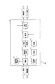
- the vehicle control device 10 effectively includes a recognition unit 11, a collision time calculation unit 12, an operation region setting unit 13, an operation timing setting unit 14, a correction unit 15, an operation determination unit 16, a determination region setting unit 17, and a time measuring unit 18. And a determination unit 19.
- the recognition unit 11 periodically acquires the first detection information from the radar device 21 and acquires the second detection information from the imaging device 22 periodically.
- the recognition part 11 is the 1st position information which is the position (namely, reflection position of a corresponding radar target) obtained from the 1st detection information for every radar target, and the 2nd detection information for every imaging target
- the same radar target and imaging target are located in the vicinity of the first position information and the second position information.
- the target position is determined and the corresponding first position information and second position information are associated with each other.
- a state where the first position information and the second position information match or are close to each other, that is, a state where the position of the target can be accurately obtained by the radar device 21 and the imaging device 22 is referred to as a fusion state. .
- the recognition unit 11 includes acquisition of first detection information for each radar target, acquisition of second detection information for each imaging target, and acquisition of fusion information of the target detected in the fusion state. Is executed periodically. And the recognition part 11 is the position information (fusion information) of the radar target, the imaging target, and the target detected in the fusion state (hereinafter also referred to as a fusion-based target) in each cycle. In this case, the identification information is also stored in the memory, for example, as a detection history.
- the position information in the first detection information, the second detection information, and the fusion information obtained from the target includes at least a position along the traveling direction (vertical direction) of the vehicle 40 in the detection shape of the target ( Vertical position) and a position (horizontal position) along a direction (lateral direction) orthogonal to the traveling direction of the host vehicle 40 is included.
- the recognition unit 11 refers to the detection history based on the identification information of the fusion target in each cycle, and determines whether the fusion target is in the fusion state from the past. I do. When it is determined that the fusion target is continuously in the fusion state, the recognition unit 11 has the fusion target at the position (that is, the first position based on the detection result of the radar device 21). It is determined that it exists. If the fusion target is not detected in a certain cycle, the recognition unit 11 refers to the detection history of the fusion target, and the predetermined period corresponds to the past position (for example, the position in the previous cycle). Treat as a fusion target.
- the recognizing unit 11 recognizes a number of assumed targets (vehicles, pedestrians, roadside objects, etc.) prepared in advance and stored in the memory for the second detection information for the fusion target. Perform pattern matching using feature patterns. Then, the recognition unit 11 associates a corresponding type with the fusion target based on the pattern matching result.
- the types of targets include automobiles, motorcycles, bicycles, pedestrians, and various road structures. A motorcycle and a bicycle may be combined into a motorcycle.
- the recognition unit 11 associates the relative position and relative speed of the fusion target with respect to the host vehicle 40 for each fusion target.
- the relative position a horizontal position indicating a relative distance in a direction orthogonal to the traveling direction of the host vehicle 40 and a vertical position that is a relative position in the traveling direction of the host vehicle 40 are obtained.
- the recognition part 10 is based on the relative position and relative speed of each fusion target, the lateral speed which is a relative speed about the direction (horizontal direction) orthogonal to the advancing direction of the own vehicle 40, and the advancing of the own vehicle 40.
- a longitudinal speed that is a relative speed in the direction (vertical direction) is calculated.
- the recognizing unit 11 subdivides the type of the fusion target using the type determined for the fusion target, the lateral speed, and the vertical speed. For example, if the fusion target is a vehicle, the recognizing unit 11 uses the vertical speed to make the vehicle travel ahead in the traveling direction of the host vehicle 40 in the same direction as the host vehicle 40. The oncoming vehicle traveling in the opposite lane ahead of the traveling direction of the host vehicle 40 and the stationary vehicle stopped in front of the traveling direction of the host vehicle 40 can be distinguished.
- the recognition unit 11 uses the own vehicle speed and the lateral speed and the vertical speed of the fusion target so that the front of the own vehicle 40 is moved in the same direction as the own vehicle 40.
- a preceding bicycle that travels toward the vehicle an opposite bicycle that travels forward in the direction of travel of the host vehicle 40 in a direction opposite to the host vehicle 40, a stationary bicycle that stops in front of the travel direction of the host vehicle 40, and It can be distinguished from crossing bicycles that cross the front in the direction of travel.
- the recognizing unit 11 uses the host vehicle speed and the vertical speed to automatically move the front of the host vehicle 40 in the traveling direction.
- the collision time calculation unit 12 calculates a collision prediction time which is a time until the vertical position of the target indicating the relative distance between the host vehicle 40 and the recognized target becomes zero. Specifically, the collision time calculation unit 12 divides the vertical position of the recognized target by the vertical speed that is the relative speed between the own vehicle 40 and the recognized target, and the own vehicle 40 determines the obtained time. The margin time until it is predicted to collide with a recognized target (collision margin time) or the prediction time (collision prediction time) is used. At this time, when the vertical speed of the recognized target is zero or when the vertical speed takes a negative value (when the host vehicle 40 and the recognized target move away), the vertical position of the recognized target is reduced. Therefore, the collision time calculation unit 12 does not calculate the collision prediction time.
- the collision time calculation unit 12 uses the relative acceleration in addition to the relative distance and the relative speed of the recognized target, so that the collision target is equal acceleration with respect to the host vehicle 40.
- the predicted collision time may be calculated as an exercise. In this case, even when the relative speed between the own vehicle 40 and the recognized target is a negative value (when the own vehicle 40 and the recognized target move away at the time of calculation), the relative acceleration is a positive value. When the relative speed changes to the positive value side, the collision time calculation unit 12 calculates the collision prediction time.
- the operation area setting unit 13 sets an operation area having a predetermined width in the lateral direction orthogonal to the traveling direction of the host vehicle 40.
- This operation area is an area for determining whether or not the lateral position of the recognized target is a position where the safety device should be operated. That is, if the lateral position of the recognized target is within the operation region, the operation region setting unit 13 determines that one condition for operating the safety device is satisfied.
- region may be different about each function of a safety device, and is good also as the same thing.
- the operation area setting unit 13 sets the width of the operation area of the alarm device 31 to the largest. This is because the vehicle control device 10 can avoid a collision without issuing a control command to the brake device 32 if the driver notices the danger of the collision by the warning device 31 and performs an operation to avoid the collision.
- the operation timing setting unit 14 sets the operation timing of each safety device. This operation timing is compared with the above-described collision prediction time. Then, when the position of the recognized target is within the operation region and the predicted collision time is less than or equal to the operation timing, the operation timing setting unit 14 operates the safety device. That is, it can be said that the greater the operation timing is set, the more the safety device operates even when the predicted collision time is longer, and the safety device is operated earlier.
- This operation timing is set to a different value for each function of the safety device.
- the operation timing of the alarm device 31 is set as the earliest timing among all the safety devices 31 and 32. This is because when the driver notices the possibility of a collision between the host vehicle 40 and the target by the alarm device 31 and depresses the brake pedal of the host vehicle 40, the brake device 32 is activated in response to the depression of the brake pedal. This is because, by braking the host vehicle 40, the vehicle control device 10 can avoid a collision without issuing a control command to the brake device 32.
- the operation timing of the brake device 32 is individually provided for the brake assist function and the automatic brake function. These operation timings may be the same value or different ones.
- the traveling direction of the host vehicle 40 is a vertical axis (y axis), and the direction orthogonal to the vertical axis is a horizontal axis (x axis).
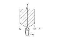
- the working area has a predetermined width in the x-axis direction, and the right width XR and the left width XL that indicate the width in the left-right direction of the working area are values that are predetermined for each type of target.
- T which is the operation timing, is determined in the y-axis direction, and the value obtained by multiplying the operation timing by the relative speed (vertical speed) between the vehicle 40 and the target indicates the position.
- the depth of is in accordance with the value of the operation timing.
- the operation timing is also set in advance for each type of target.
- region is provided along the shape of the road where the own vehicle 40 drive
- the operation region set by the operation region setting unit 13 and the operation timing set by the operation timing setting unit 14 are corrected by the correction unit 15 and then input to the operation determination unit 16.
- the operation determining unit 16 determines whether or not the lateral position of the recognized target is within the operation region, and if the lateral position of the recognized target is within the operation region, one condition for operating the safety device is satisfied. judge. Similarly, the operation determination unit 16 determines whether or not the predicted collision time of the recognized target is less than or equal to the operation timing. If the predicted collision time is less than or equal to the operation timing, one condition for operating the safety device is satisfied. It is determined that If the operation determination unit 16 determines that all the conditions for operating the safety device are satisfied, the operation determination unit 16 transmits an operation command to the safety device and causes the safety device to execute a corresponding function.
- the recognized target is, for example, a bicycle and the bicycle moves across the front of the own vehicle 40
- the recognized target is the vehicle width of the own vehicle 40 (the own vehicle width).
- the width of the operation area is set to a width obtained by adding several meters to the width of the own vehicle.
- the collision with the own vehicle 40 such as traveling diagonally forward of the own vehicle 40 in the same direction or in the opposite direction to the own vehicle 40, etc.
- the safety device is activated even for a bicycle with a low possibility of the accident.
- the operation determination unit 16 uses a relative speed between the host vehicle 40 and the bicycle, and is positioned obliquely forward of the host vehicle 40 and travels in the same direction as the host vehicle 40 or in the opposite direction. Processing to suppress unnecessary operation is performed. Specifically, the correction unit 15 performs processing (delay processing) for reducing the width of the operation region (reduction processing) and delaying the operation timing.
- the bicycle may behave in a lateral direction while traveling.
- the lateral speed is detected.
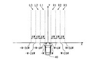
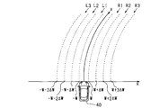
- the determination region setting unit is configured to distinguish between a target moving in the same direction or the reverse direction of the host vehicle 40 and a target that is about to cross the front of the host vehicle 40 in the traveling direction. 17 sets a determination region diagonally forward in the traveling direction of the host vehicle 40. This determination area will be described with reference to FIG. In FIG. 3, the right direction of the host vehicle 40 is the positive direction of the x-axis.
- the determination area is composed of a plurality of areas divided in the horizontal direction, which is a direction orthogonal to the traveling direction of the host vehicle 40. Each region is partitioned by a dividing line parallel to the traveling direction of the host vehicle 40, whereby each region is provided in parallel to the traveling direction of the host vehicle 40.
- a right first region R1, a right second region R2, and a right third region R3 are provided on the right side in the traveling direction of the host vehicle 40 in order from the one closer to the traveling direction of the host vehicle 40.
- a left first region L1, a left second region L2, and a left third region L3 are provided on the left side in the traveling direction of the host vehicle 40 in order from the one closer to the traveling direction of the host vehicle 40.
- Both the end of the right first region R1 on the traveling direction side of the own vehicle 40 and the end of the left first region L1 on the traveling direction side of the own vehicle 40 are both from the traveling direction of the own vehicle 40. They are spaced apart by W, indicating half the width. This means that a determination region is not provided in the range of the vehicle width in front of the traveling direction of the vehicle 40.
- the lateral widths of the regions R1, R2, R3, L1, L2, and L3 are all ⁇ W.
- ⁇ W which is the width in the horizontal direction, is set to, for example, about 1 to 2 m, but may be set based on the detection cycle of the target position and the assumed speed of the target. 2 is provided on the left side of the right end of the right third region R3, and the left end of the operation region is on the left side of the left third region L3. It is provided on the right side of the end.
- the time measuring unit 18 uses the lateral position of the recognized target to determine which of the areas in the determination area is present, and measures the time during which the recognized target stays continuously in the same area as the stay time. That is, the timing unit 18 starts timing when it is determined that the recognized target stays in any region in the determination region, and ends timing when the target moves from the region to another region.
- the timing processing of the time measuring unit 18 includes the time between the movement of the most recently recognized target area to the present time, the movement between the most recently recognized target areas, and the movement between the most recently recognized target areas.
- the stay time counted during the period between the movement of the recognized target area and the movement of the area immediately before the movement of the recognized target area is collectively held as the stay time.
- the determination unit 19 may cross the course of the own vehicle 40 based on whether the recognized target is running in parallel with the host vehicle 40 based on the movement history and staying time between the regions in the determination region based on the recognized target. It is determined whether an operation (crossing operation) is being performed. At this time, when the movement between the areas in the direction in which the recognized target approaches the own vehicle 40 continuously occurs, the first condition for determining that the crossing operation is being performed is satisfied. In addition, if the stay time is shorter than the predetermined time, the second condition for determining that the crossing operation is being performed is satisfied. When both the first condition and the second condition are satisfied, the determination unit 19 assumes that the recognized target is performing a crossing operation, and does not perform the operation region reduction process and the operation timing delay process.
- the determination unit 19 performs an operation region reduction process and an operation timing delay process to suppress unnecessary operation of the safety device.
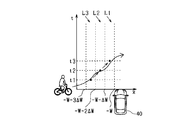
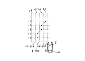
- FIG. 4 is a diagram illustrating a temporal change in the lateral position of the recognized target when the recognized target performs a crossing operation.
- the horizontal axis is the horizontal position of the recognized target
- the vertical axis is the time.
- the time intervals shown on the vertical axis are each one control cycle, and when the recognized target is continuously present in the same region for three or more control cycles, the second condition for performing the correction process is satisfied. If the stay time is less than 3 control cycles, the second condition for performing the correction process is not satisfied.
- the recognized target is present in the third region L3 at time t1, is present in the second region L2 at time t2, and is present in the first region L1 at time t3. .
- the movement history between the areas of the recognized target moves in the approaching direction with respect to the route of the own vehicle 40 between the time t1 and the time t2, and further moves between the time t2 and the time t3. It shows that the movement in the approaching direction with respect to the course of was performed. Therefore, it is highly possible that the recognized target enters the course of the host vehicle 40, and correction processing is not performed.
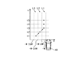
- FIG. 5 is a diagram showing a temporal change in the lateral position of the recognized target when the recognized target runs parallel to the host vehicle 40.
- the recognized target is present in the second region L2 at time t1, is present in the third region L3 from time t2 to time t3, and is present in the second region L2 from time t4 to time t5. .
- time t4 and time t5 it is determined that the movement between the nearest areas of the recognized target is the approaching direction with respect to the course of the host vehicle 40 from time t3 to time t4.
- the recognized target does not continuously move in the approaching direction to the own vehicle 40. .
- the recognition target is likely to be running in parallel with the host vehicle 40, and the possibility of entering the course of the host vehicle 40 is low.
- the recognized target is traveling in the vicinity between the second region L2 and the third region L3.
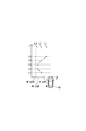
- the vertical axis represents X as the width of the operation region (right width XR, left width XL) and T as the operation timing.
- the horizontal axis represents the relative speed between the vehicle 40 and the recognized target, but other parameters may be used.
- the width of the operation region and the operation timing when correction processing is not performed are indicated by solid lines, and are Xmax and Tmax, which are upper limit values, respectively. These are predetermined values and can also be referred to as reference values.
- the width of the operation region and the operation timing when correction processing is performed are indicated by broken lines.
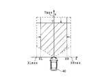
- FIG. 7 shows the operation region and operation timing corrected by the correction unit 15 in this way.
- the width of the operation region (right width XR, left width XL) is set to a value smaller than the reference value (right upper limit value XRmax, left upper limit value XLmax), and the operation timing is set.
- the width of the operation region (right width XR, left width XL) is set to a value smaller than the reference value (right upper limit value XRmax, left upper limit value XLmax), and the operation timing is set.
- FIG. 8 is another example showing a temporal change in the lateral position of the recognized target when the recognized target performs a crossing operation.
- the recognized target is present in the third region L3 at time t1 and time t2, is present in the second region L2 at time t3 and time t4, and is present in the first region L1 at time t5. ing.
- the staying time in the third region L3 and the second region L2 is smaller than a predetermined value (three control cycles) and satisfies the second condition in which correction processing is not performed.
- the vehicle 40 moved in the approach direction with respect to the route between the time t1 and the time t2, and the vehicle 40 further moved in the approach direction with respect to the route between the time t2 and the time t3. Means that. Therefore, although the lateral speed of the recognized target is slower than that shown in FIG. 4, it is highly likely that the recognized target will enter the course of the host vehicle 40, and correction processing is not performed.
- FIG. 9 is an example showing the behavior of a recognized target when a transition is made from the case where the condition for not performing the correction process is satisfied to the case where the condition for performing the correction process is satisfied.
- the recognized target is present in the third region L3 at time t1, is present in the second region L2 at time t2, and is present in the first region L1 from time t3 to time t5.
- the correction process is not performed until the time t4 when the stay time is smaller than the predetermined value.
- the stay time in the first area L1 that is, the stay time from the movement of the latest recognized target area between the areas (time t2 to t3) to the present time (time t5) is a predetermined value (3 control cycles). It becomes the above value. Therefore, the correction process is started at time t5.
- FIG. 10 is an example showing the behavior of a recognized target when transitioning from the case where the condition for performing the correction process is satisfied to the case where the condition for not performing the correction process is satisfied.
- the recognized target is present in the second region L2 at time t1, is present in the third region L3 at times t2 and t3, and is present in the second region L2 at time t4.
- Correction processing is performed to mean that the recognized target has moved away from the host vehicle 40 from time t1 to time t2. Also, at time t3, the movement between the nearest areas of the recognized target is away from the own vehicle 40 at times t1 to t2, so the correction process is continued.
- the recognition target has moved in the direction approaching the course of the own vehicle 40 at time t4, the movement between the previous recognition target areas is the own vehicle at time t1 to t2. Since it is in a direction away from 40, the correction process is continued.
- the movement between the nearest areas of the recognized target is the approach direction with respect to the course of the own vehicle 40 at time t4 to t5, and the movement between the previous areas is also the movement of the own vehicle 40 at time t3 to t4.
- the staying time at time t5 is smaller than a predetermined value. Therefore, it is assumed that the conditions for not performing the correction process are satisfied.
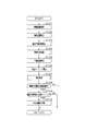
- the vehicle control device 10 acquires detection information from the radar device 21 and the imaging device 22, performs target recognition processing (S101), and calculates the position of each recognized target (S102). Then, a collision prediction time is calculated based on the position of the recognized target and the relative speed of the recognized target with respect to the vehicle 40 (S103). Subsequently, the vehicle control device 10 recognizes a road shape on which the host vehicle 40 travels (S104), calculates an operation region based on the road shape (S105), and calculates an operation timing (S106). When these operation regions and operation timings are calculated, determination processing using the determination regions shown in FIGS. 3 to 5 is performed to determine whether or not the calculated operation regions and operation timings should be corrected (S107).
- the position of the recognized target is within the operating region (S108).
- the position of the recognized target is within the operation region (S108: YES)
- the position of the recognized target is not within the operation region (S108: NO), or when the predicted collision time is not less than the operation timing (S109: NO), at least one of the conditions for operating the safety device is not satisfied. Then, the series of processes is terminated without operating the safety device.
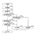
- FIG. 12 is a subroutine of the determination process in S107.
- the vehicle control device 10 sets a determination area diagonally forward in the traveling direction of the host vehicle 40 (S201), and measures the staying time in the determination area of the recognized target (S202). Subsequently, it is determined whether or not the movement between the nearest areas of the recognized target is a direction approaching the course of the host vehicle 40 (S203).
- the determination area is provided in parallel with the traveling direction of the host vehicle 40 as described above. Therefore, when the own vehicle 40 is traveling on a curved section of the road, it is set as a curved area according to the curvature of the curved section as shown in FIG.
- the vehicle control device 10 has the following effects.
- the target device When operating a safety device for a recognized target moving across the front in the direction of travel of the host vehicle 40, if the target device has entered the width of the host vehicle and the safety devices 31, 32 have been operated There may be a delay in the operation of the safety devices 31 and 32. Therefore, it is necessary to set the width of the operation region wider than the width of the own vehicle.
- the recognition target is a two-wheeled vehicle such as a bicycle that runs in parallel with the host vehicle 40, the bicycle may run while wobbling in the lateral direction. If it is determined that the behavior is crossing, unnecessary operation of the safety devices 31 and 32 may occur.
- the width and the operation timing of the operation region are set to values smaller than the reference value. Unnecessary operation of the safety devices 31 and 32 can be suppressed.
- the tendency of the movement direction of the recognized target can be obtained from the movement history between the areas. Furthermore, if the stay time of the recognized target in each region is added to the tendency, the moving direction of the recognized target can be determined.
- the vehicle control device 10 since the correction process is performed using the movement history and the stay time obtained from the determination region and the position of the recognized target, the width of the operation region according to the moving direction of the recognized target. In addition, the operation timing can be changed, and the inoperative and unnecessary operations of the safety devices 31 and 32 can be suppressed.
- the detected position may vary based on the horizontal width of the target. For this reason, for example, when the position based on the left end of the target is detected in the previous control cycle and the position based on the right end of the target is detected in the subsequent control cycle, the target moves in the right direction. There is a possibility of misjudging that it is moving.
- the vehicle control device 10 since it is determined in which of the determination areas having a width in the horizontal direction the recognized target is present, the position of the detected recognized target varies. Although the movement of the recognized target to the adjacent area may be determined, the continuous movement between the areas is not determined. Therefore, it is possible to suppress erroneous determination of the moving direction of the brocade target due to variations in detection of the position of the recognized target, and consequently, it is possible to suppress unnecessary operations of the safety devices 31 and 32.
- Second Embodiment When the target moves away from the traveling direction of the host vehicle 40, it can be said that the possibility that the host vehicle 40 and the target collide with each other is lower than when the target runs parallel to the host vehicle 40. Therefore, in the vehicle control apparatus 10 according to the present embodiment, when the recognition target moves away from the traveling direction of the host vehicle 40 using the determination region shown in the first embodiment, the case where the target object moves in parallel is used. Thus, the width of the operation region is made smaller and the operation timing is set to a smaller value.
- the correction process when the recognized target runs parallel to the host vehicle 40 is referred to as a first correction process
- the correction process when the recognized target moves away from the host vehicle 40 is referred to as a second correction process.
- the width and operation timing of the operation region when the correction process is not performed are shown by solid lines as in the first embodiment, and the width and operation timing of the operation region obtained as a result of the first correction process are shown. This is indicated by a broken line, and the width of the operation region and the operation timing obtained as a result of the second correction process are indicated by a one-dot chain line. That is, as a result of the first correction process, the width of the operation region and the operation timing are set to small values, and as a result of the second correction process, the width of the operation region and the operation timing are set to smaller values.
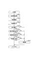
- FIG. 15 is a subroutine of the determination process of S107 in FIG.
- the vehicle control device 10 sets a determination area diagonally forward in the traveling direction of the host vehicle 40 (S301), and measures the stay time in the determination area of the recognized target (S302). Subsequently, it is determined whether or not the movement between the nearest areas of the recognized target is a direction approaching the course of the host vehicle 40 (S303).
- the recognized target When the latest movement of the recognized target is the approach direction to the course of the host vehicle 40 (S303: YES), it is determined whether or not the previous movement between the areas of the recognized target is the approach direction (S304). If the movement of the recognized target between the previous areas is in the approach direction (S304: YES), the recognized target means that the vehicle has continuously moved in the approach direction with respect to the course of the host vehicle 40, so stay It is determined whether the time is smaller than a predetermined value (S305). If the stay time is smaller than the predetermined value (S305: YES), it is highly possible that the recognized target is moving across the course of the host vehicle 40. Exit the subroutine.
- the movement between the most recent areas of the recognized target is the approach direction with respect to the course of the own vehicle 40 (S303: YES)
- the movement between the previous areas of the recognized target is the approach direction with respect to the course of the own vehicle 40. If it is not (S304: NO), since the movement of the recognized target is approaching and separating from the own vehicle 40, there is a high possibility that the recognized target is running in parallel with the own vehicle 40. Therefore, the first correction process is performed (S307), and the series of processes is terminated.
- the stay time is equal to or longer than the predetermined value (305: NO)
- the first correction process is performed (S307), and the series of processes ends.
- the first correction process may be performed.
- the vehicle control device 10 has the following effects.
- the determination region is used to determine whether or not the recognition target is moving away from the host vehicle 40, and the operation region is further reduced and the operation timing is further delayed. 2 correction processing is performed. Thereby, the unnecessary operation
- FIG. 16 is a subroutine of the determination process of S107 in FIG.
- the vehicle control device 10 acquires the behavior of the host vehicle 40 (S401), sets a determination region diagonally forward in the traveling direction of the host vehicle 40 (S402), and measures the stay time in the determination region of the recognized target. (S403). Subsequently, based on the behavior of the host vehicle 40, it is determined whether the host vehicle 40 is traveling straight (S404). When the host vehicle 40 is traveling straight (S404: YES), it is determined whether or not the movement between the nearest areas of the recognized target is a direction approaching the course of the host vehicle 40, as in the first embodiment. (S405).
- the vehicle control device 10 can suppress unnecessary operations of the safety devices 31 and 32 when it is difficult to distinguish between the crossing operation of the recognized target and the parallel running operation.
- the safety devices 31 and 32 are activated in addition to the avoidance operation, or safety contrary to the avoidance operation. If the operation of the devices 31 and 32 is performed, the operation of the safety devices 31 and 32 is an operation contrary to the intention of the driver, and is an unnecessary operation. Therefore, in the present embodiment, the correction unit 15 determines whether or not an operation for avoiding a collision with the recognized target by the driver has been performed, and when the operation is performed, the width of the operation region and the operation timing are determined. The correction process is performed.
- FIG. 17 is a subroutine of the determination process of S107 in FIG.
- the vehicle control device 10 sets a determination area diagonally forward in the traveling direction of the host vehicle 40 (S501), and measures the stay time in the determination area of the recognized target (S502). Subsequently, it is determined whether or not an operation for avoiding a collision has been performed by the driver (S503). When the avoidance operation by the driver is not performed (S503: NO), whether or not the movement between the nearest areas of the recognized target is the direction approaching the course of the own vehicle 40, as in the first embodiment. Is determined (S504).
- the movement between the nearest areas of the recognition target is the approach direction with respect to the traveling direction of the host vehicle 40 (S504: YES)
- the movement between the previous areas of the recognition target is the approach direction with respect to the traveling direction of the host vehicle 40. It is determined whether or not there is (S505).
- the recognized target continuously moves in the approach direction with respect to the traveling direction of the host vehicle 40. Therefore, it is determined whether or not the stay time is equal to or less than a predetermined value (S506).
- the recognition target is likely to be moving across the course of the host vehicle 40, so the correction process of the operation region and the operation timing is not performed.
- the subroutine is finished as it is.
- the vehicle control device 10 can suppress the operation of the safety devices 31 and 32 against the intention of the collision avoidance operation by the driver.
- both the operation region and the operation timing are corrected.
- one of the operation region and the operation timing may be corrected. Even in this case, an effect of suppressing unnecessary operations of the safety devices 31 and 32 can be achieved.
- the width of each region is made equal, but it may not be equal. Variation in position detection by the radar device 21 increases as the distance from the host vehicle 40 increases. Therefore, it is possible to set the width wider as the region is further away from the host vehicle 40. By doing so, it is possible to suppress a situation in which the movement of the recognized target between the regions provided far away is frequently detected.
- each region is provided in parallel with the traveling direction of the host vehicle 40.
- the region may be provided so that the width of each region increases as it goes farther in the vertical direction.
- three determination areas are provided in the left-right direction of the host vehicle 40, but four or more determination areas may be provided.
- the determination area is set in this way, even if the recognized target moves three or more times in the same direction, it may be determined that the recognized target has been continuously moved in the course direction of the vehicle 40. Good.
- the correction amount in the correction process may be changed according to the stay time.
- the width of the operation region and the operation timing are set as reference values, and when it is determined that the recognized target is running in parallel, A value smaller than the reference value was set.
- the width and operation timing of the operation area are set as reference values, and when it is determined that the recognized target performs a crossing action, it is larger than the reference value. It may be set to a value.
- the staying time is used to determine the movement tendency of the recognized target, but the determination may be made using only movement between regions.
- a two-wheeled vehicle such as a bicycle is likely to run in parallel in the same direction as or in the opposite direction of the own vehicle 40 in the forward direction of the own vehicle 40.
- a vehicle or a pedestrian having four or more wheels is less likely to run in parallel in the same direction as the host vehicle 40 or in the opposite direction of the host vehicle 40 in the traveling direction. Therefore, the determination area setting unit 17 may set the determination area only when the recognition target is a two-wheeled vehicle, and the correction unit 15 may perform correction processing when the recognition target is a two-wheeled vehicle.
- the driver drives a vehicle on which the vehicle control device 10 is mounted.
- the vehicle control device 10 may be mounted on a vehicle having an automatic driving function.
- the alarm function, the brake assist function, and the automatic brake function are given as the functions of the safety device, the functions of the safety device are not limited to these.
- a function of performing a steering operation in a direction that avoids a collision with a recognized target may be employed.
Landscapes
- Engineering & Computer Science (AREA)
- Radar, Positioning & Navigation (AREA)
- Remote Sensing (AREA)
- Mechanical Engineering (AREA)
- Physics & Mathematics (AREA)
- Transportation (AREA)
- Automation & Control Theory (AREA)
- General Physics & Mathematics (AREA)
- Computer Networks & Wireless Communication (AREA)
- Electromagnetism (AREA)
- Human Computer Interaction (AREA)
- Traffic Control Systems (AREA)
- Control Of Driving Devices And Active Controlling Of Vehicle (AREA)
- Regulating Braking Force (AREA)
Abstract
車両制御装置は、衝突予測時間と比較することにより安全装置を作動させるか否かを判定する作動タイミングを設定するタイミング設定部と、進行方向前方であって且つ自車の斜め前方に、横方向に向けて分割された複数の判定領域を設定する判定領域設定部と、前記作動領域の幅を変更する処理及び前記作動タイミングを変更する処理の少なくとも一方の処理である補正処理を、認識物標の前記判定領域間での移動履歴に基づいて行う補正部と、前記認識物標の位置が前記作動領域内であり、且つ、前記衝突予測時間が前記作動タイミングを下回った場合に、前記安全装置を作動させる作動判定部と、を備えている。
Description
本開示は、自車両の物標に対する衝突を回避すべく安全装置を作動させる車両制御方法および装置に関する。
従来、自車と、自車の進行方向前方に位置する他車両、歩行者、又は道路構造物等の障害物(物標)との衝突被害を軽減または防止する、プリクラッシュセーフティ(Pre-crash safety:PCS)が公知である。このPCSシステムでは、自車と障害物との相対距離と、相対速度又は相対加速度とに基づいて、自車と障害物との衝突までの余裕時間である衝突余裕時間(衝突予測時間Time to Collision: TTC)を求める。そして、PCSシステムは、求めた衝突余裕時間に基づいて、自車の運転者に対して警報装置により接近を報知したり、自車の制動装置を作動させたりしている。
このPCSシステムに関する公知技術として、特許文献1に記載の車両制御装置がある。特許文献1に記載の車両制御装置では、自車の進路の側方に領域を設け、その領域に物標が存在する場合、自車の最高速度を制限する制御を行っている。
自車の進路の側部に存在する物標は、自車と並走する挙動をとることもあれば、自車の進路を横切る挙動をとることもある。すなわち、物標の挙動に応じて、自車と衝突する可能性は変化する。特許文献1に記載の車両制御装置では、自車の進路の側方に設けた領域に物標が存在するか否かを判定することはできるものの、物標の挙動に応じて自車の制御を行うことはできない。
この点、自車の進行方向前方を横切る物標(例えば二輪車)との衝突を回避すべく、安全装置を作動させるのならば、その二輪車が自車の進行方向の斜め前方に存在する時点で、安全装置を作動させる必要がある。ところが、二輪車は、自車の進行方向斜め前方を自車と同方向へと走行する場合もあり、二輪車は左右方向にふらつきながら走行することがある。このとき、ふらつきに伴う二輪車の自車方向への接近を該二輪車の自車の前方を横切る動作であると判定すれば、自車の安全装置の不要作動が生ずることがある。
本開示の一態様は、上記課題を解決するためになされたものであり、その主たる目的は、自車の進行方向前方を横切る可能性の低い物標に対する安全装置の不要作動を抑制することが可能な車両制御装置を提供することにある。
本開示の第1の態様は、自車の進行方向前方に存在する物標を認識し、この認識物標と自車とが衝突する可能性に応じて、自車と認識物標との衝突の回避又は衝突被害を軽減する装置を安全装置として作動させる車両制御装置である。この車両制御装置は、前記自車と前記認識物標とが衝突すると予測されるまでの予測時間である衝突予測時間を算出する衝突時間算出部と、前記進行方向前方に、前記自車の進路に直交する方向である横方向に所定の幅を有する領域である作動領域を設定する作動領域設定部と、前記衝突予測時間と比較することにより前記安全装置を作動させるか否かを判定する作動タイミングを設定するタイミング設定部と、前記進行方向前方であって且つ前記自車の斜め前方に、前記横方向に向けて分割された複数の判定領域を設定する判定領域設定部と、
前記作動領域の幅を変更する処理及び前記作動タイミングを変更する処理の少なくとも一方の処理である補正処理を、前記認識物標の前記判定領域間での移動履歴に基づいて行う補正部と、前記認識物標の位置が前記作動領域内であり、且つ、前記衝突予測時間が前記作動タイミングを下回った場合に、前記安全装置を作動させる作動判定部と、を備えている。
前記作動領域の幅を変更する処理及び前記作動タイミングを変更する処理の少なくとも一方の処理である補正処理を、前記認識物標の前記判定領域間での移動履歴に基づいて行う補正部と、前記認識物標の位置が前記作動領域内であり、且つ、前記衝突予測時間が前記作動タイミングを下回った場合に、前記安全装置を作動させる作動判定部と、を備えている。
また、本開示の第2の態様は、自車の進行方向前方に存在する物標を認識し、この認識物標と自車とが衝突する可能性に応じて、自車と認識物標との衝突の回避又は衝突被害を軽減する装置を安全装置として作動させる車両制御装置が実行する車両制御方法である。この車両制御方法は、前記自車と前記認識物標とが衝突すると予測されるまでの予測時間である衝突予測時間を算出する衝突時間算出ステップと、前記進行方向前方に、前記自車の進路に直交する方向である横方向に所定の幅を有する領域である作動領域を設定する作動領域設定ステップと、前記衝突予測時間と比較することにより前記安全装置を作動させるか否かを判定する作動タイミングを設定するタイミング設定ステップと、前記進行方向前方であって且つ前記自車の斜め前方に、前記横方向に向けて分割された複数の判定領域を設定する判定領域設定ステップと、前記作動領域の幅を変更する処理及び前記作動タイミングを変更する処理の少なくとも一方の処理である補正処理を、前記認識物標の前記判定領域間での移動履歴に基づいて行う補正ステップと、前記認識物標の位置が前記作動領域内であり、且つ、前記衝突予測時間が前記作動タイミングを下回った場合に、前記安全装置を作動させる作動判定ステップと、を実行する。
本開示の第1および第2の態様に係る車両制御装置および方法はそれぞれ、自車の進行方向の斜め前方において、横方向に分割された複数の判定領域を設定し、その領域間での認識物標の移動履歴により、該認識物標の移動方向の傾向を求めている。そして、本開示の第1および第2の態様に係る車両制御装置および方法はそれぞれ、その傾向により、認識物標が自車の進路に接近しているものであるのか否かを判定することができる。
さらに、上記車両制御装置および方法はそれぞれ、判定領域及び認識物標の位置から得られた移動履歴に基づいて、補正処理として、認識物標が自車の進路に接近しているものであるか否かに応じて作動領域の幅及び作動タイミングの少なくとも一方を変更するように構成されている。この構成により、安全装置の不作動及び不要作動を抑制することができる。
さらに、上記車両制御装置および方法はそれぞれ、判定領域及び認識物標の位置から得られた移動履歴に基づいて、補正処理として、認識物標が自車の進路に接近しているものであるか否かに応じて作動領域の幅及び作動タイミングの少なくとも一方を変更するように構成されている。この構成により、安全装置の不作動及び不要作動を抑制することができる。
以下、本開示の各実施形態を図面に基づいて説明する。なお、以下の各実施形態相互において、互いに同一もしくは均等である部分には、図中、同一符号を付しており、同一符号の部分についてはその説明を援用する。
<第1実施形態>
本実施形態に係る車両制御装置は、車両(自車)40に搭載され、自車40の進行方向(例えば前方)の周囲に物標が存在するか否かを判定し、物標が存在すると判定した場合、その物標と自車両40との衝突を回避すべく、若しくは衝突被害を軽減すべく制御を行うPCSシステムとして機能する。
本実施形態に係る車両制御装置は、車両(自車)40に搭載され、自車40の進行方向(例えば前方)の周囲に物標が存在するか否かを判定し、物標が存在すると判定した場合、その物標と自車両40との衝突を回避すべく、若しくは衝突被害を軽減すべく制御を行うPCSシステムとして機能する。
図1において、車両制御装置10は、CPU、メモリ(ROMおよびRAMを含む)、I/O等を備えたコンピュータである。この車両制御装置10は、CPUが、例えばROMにインストールされているプログラムを実行することで後述する各機能を実現する。
車両制御装置10には、各種の検知情報を入力するセンサ装置として、レーダ装置21、及び撮像装置22が接続されている。
レーダ装置21は、例えば、ミリ波帯の高周波信号を送信波とする公知のミリ波レーダであり、自車40の例えば前端部に設けられている。レーダ装置21は、自車両40の前方に延びる中心軸を有し、この中心軸を中心として水平方向に広がる所定の視野角(検知角、走査角)を有する領域を、物標を検知可能な検知範囲として有しており、検知範囲内の物標の位置を検出する。具体的には、レーダ装置21は、送信アンテナを介して検知範囲に対して所定周期で探査波を送信し、複数の受信アンテナにより、物標が前記探査波を反射することにより得られた反射波を受信する。この探査波の送信時刻と反射波の受信時刻とにより、レーダ装置21は、自車40と物標との距離を算出する。また、物標が前記探査波を反射することにより得られた反射波の、ドップラー効果により変化した周波数により、自車40と物標との間の相対速度を算出する。
加えて、レーダ装置21は、複数の受信アンテナが受信した反射波の位相差により、前記反射波に対応する物標の方位を算出する。なお、物標の位置及び方位が算出できれば、レーダ装置21は、その物標の、自車両40に対する相対位置を特定することができる。なお、レーダ装置21は、所定周期(以下、第1の周期とする)毎に、探査波の送信、前記探査波に基づく反射波の受信、受信した反射波に基づく物標の反射位置(自車両40との間の相対位置)及び相対速度の算出を行い、算出した物標の反射位置と相対速度とを、該物標の第1検知情報として運転支援ECU10に送信する。なお、レーダ装置21により検知された物標をレーダ物標ともいう。
撮像装置22は、例えばCCDカメラ、CMOSイメージセンサ、近赤外線カメラ等の単眼撮像装置である。撮像装置22は、例えば、自車40の車幅方向中央の所定高さに取り付けられており、自車40の前方に延びる光軸を有し、自車40の前方へ向けて、上記光軸を中心に所定角度(画角)範囲で広がる領域(撮像範囲)を、上記所定の高さ、すなわち俯瞰視点から撮像する。
撮像装置22は、撮像した画像、すなわちフレーム画像における、物標の存在を示す特徴点を抽出する。具体的には、撮像装置22は、撮像した画像の輝度情報に基づきエッジ点を抽出し、抽出したエッジ点に対してハフ変換を行う。ハフ変換では、例えば、エッジ点が複数個連続して並ぶ直線上の点や、直線どうしが直交する点が特徴点として抽出される。なお、撮像装置22は、レーダ装置21の第1の周期と同じ若しくは異なる周期(以下第2の周期)毎に、フレーム画像の撮像及び物標の特徴点の抽出を行い、その物標の特徴点の抽出結果を、該物標の第2検知情報として車両制御装置10へ送信する。なお、撮像装置22により検知された物標を撮像物標ともいう。
自車40は、車両制御装置10からの制御指令により駆動する安全装置として、警報装置31及びブレーキ装置32を備えている。
警報装置31は、自車40の車室内に設置されたスピーカやディスプレイである。車両制御装置10が、物標に衝突する可能性が高まったと判定した場合には、その車両制御装置10からの制御指令により、警報音や警報メッセージ等を出力して運転者に衝突の危険を報知する。
ブレーキ装置32は、自車40を制動する制動装置である。車両制御装置10が、物標に衝突する可能性が高まったと判定した場合には、その車両制御装置10からの制御指令により作動する。具体的には、ブレーキ装置32は、運転者によるブレーキ操作に基づく自車40に対する制動力をより強くしたり(ブレーキアシスト機能)、運転者によりブレーキ操作が行われてなければ自車40の自動制動を行ったりする(自動ブレーキ機能)。
車両制御装置10は、能的に、認識部11、衝突時間算出部12、作動領域設定部13、作動タイミング設定部14、補正部15、作動判定部16、判定領域設定部17、計時部18、および判定部19を備えている。
認識部11は、レーダ装置21から周期的に第1検知情報を取得し、撮像装置22から周期的に第2検知情報を取得する。
そして、認識部11は、レーダ物標毎の第1検知情報から得られる位置(すなわち、対応するレーダ物標の反射位置)である第1の位置情報と、撮像物標毎の第2検知情報から得られる該撮像物標の特徴点である第2の位置情報とに基づいて、該第1の位置情報と第2の位置情報とが近傍に位置するレーダ物標および撮像物標を、同じ物標であると判断し、対応する第1の位置情報および第2の位置情報を対応付ける。すなわち、レーダ物標の第1の位置情報の近傍に、撮像物標の第2の位置が存在する場合、その第1の位置情報に基づく位置に実際の物標が存在する可能性が高い。この第1の位置情報と第2の位置情報とが一致または近接している状態、すなわち、レーダ装置21及び撮像装置22により物標の位置が精度よく所得できている状態を、フュージョン状態と称する。
そして、認識部11は、レーダ物標毎の第1検知情報から得られる位置(すなわち、対応するレーダ物標の反射位置)である第1の位置情報と、撮像物標毎の第2検知情報から得られる該撮像物標の特徴点である第2の位置情報とに基づいて、該第1の位置情報と第2の位置情報とが近傍に位置するレーダ物標および撮像物標を、同じ物標であると判断し、対応する第1の位置情報および第2の位置情報を対応付ける。すなわち、レーダ物標の第1の位置情報の近傍に、撮像物標の第2の位置が存在する場合、その第1の位置情報に基づく位置に実際の物標が存在する可能性が高い。この第1の位置情報と第2の位置情報とが一致または近接している状態、すなわち、レーダ装置21及び撮像装置22により物標の位置が精度よく所得できている状態を、フュージョン状態と称する。
認識部11は、上記レーダ物標毎の第1検知情報の取得、撮像物標毎の第2検知情報の取得、およびフュージョン状態において検知された物標のフュージョン情報の取得を含む物標認識処理を周期的に実行する。そして、認識部11は、各周期において、レーダ物標、撮像物標、およびフュージョン状態において検知された物標(以下、フュージョン物標(fusion-based target)とも記載する)の位置情報(フュージョン情報の場合識別情報も含む)を検知履歴として例えば上記メモリに記憶する。
なお、物標から求められた第1検知情報、第2検知情報、およびフュージョン情報における位置情報には、少なくとも当該物標の検知形状における自車40の進行方向(縦方向)に沿った位置(縦位置)、および自車40の進行方向に直交する方向(横方向)に沿った位置(横位置)を含んでいる。
なお、物標から求められた第1検知情報、第2検知情報、およびフュージョン情報における位置情報には、少なくとも当該物標の検知形状における自車40の進行方向(縦方向)に沿った位置(縦位置)、および自車40の進行方向に直交する方向(横方向)に沿った位置(横位置)を含んでいる。
フュージョン物標については、認識部11は、各周期において、そのフュージョン物標の識別情報に基づいて検知履歴を参照し、該フュージョン物標が過去から継続してフュージョン状態であるか否かの判定を行う。そして、そのフュージョン物標が継続してフュージョン状態であると判定された場合、認識部11は、その位置(すなわち、レーダ装置21の検出結果に基づく第1の位置)に、そのフュージョン物標が存在していると決定される。また、フュージョン物標について、ある周期において未検知状態となれば、認識部11は、そのフュージョン物標の検知履歴を参照し、所定期間はその過去位置(例えば、前周期における位置)に対応するフュージョン物標が存在するものとして扱う。
さらに、認識部11は、このフュージョン物標について、その第2検知情報に対して、予め用意され上記メモリに記憶された、想定される多数の物標(車両、歩行者、路側物等)の特徴パターンを用いるパターンマッチングを行う。そして、認識部11は、上記パターンマッチング結果に基づいて、このフュージョン物標に対し、対応する種別を関連付ける。このとき、物標の種別としては、自動車、自動二輪車、自転車、歩行者、及び、各種の道路構造物が挙げられる。なお、自動二輪車と自転車とを纏めて二輪車としてもよい。
続いて、認識部11は、フュージョン物標毎に、該フュージョン物標の自車40に対する相対位置及び相対速度を対応付ける。この相対位置としては、自車40の進行方向に直交する方向の相対距離を示す横位置と、自車40の進行方向についての相対位置である縦位置が得られる。そして、認識部10は、各フュージョン物標の相対位置および相対速度に基づいて、自車40の進行方向に直交する方向(横方向)についての相対速度である横速度と、自車40の進行方向(縦方向)についての相対速度である縦速度とを算出する。
加えて、認識部11は、フュージョン物標毎に、該フュージョン物標について、判別した種別と、横速度及び縦速度とを用いて、該フュージョン物標の種別を細分化する。
例えば、フュージョン物標が車両であれば、認識部11は、その縦速度を用いることにより、該車両を、自車40の進行方向前方を自車40と同方向に向かって走行する先行車両と、自車40の進行方向前方の対向車線を走行する対向車両と、自車40の進行方向前方で停止している静止車両との何れかに区別することができる。
例えば、フュージョン物標が車両であれば、認識部11は、その縦速度を用いることにより、該車両を、自車40の進行方向前方を自車40と同方向に向かって走行する先行車両と、自車40の進行方向前方の対向車線を走行する対向車両と、自車40の進行方向前方で停止している静止車両との何れかに区別することができる。
また、フュージョン物標が自転車であれば、認識部11は、自車速と、フュージョン物標の横速度および縦速度とを用いることにより、自車40の進行方向前方を自車40と同方向に向かって走行する先行自転車と、自車40の進行方向前方を自車40と反対方向に向かって走行する対向自転車と、自車40の進行方向前方で立ち止まっている静止自転車と、自車40の進行方向前方を横断する横断自転車とに区別することができる。
加えて、認識部11は、第1検知情報のみによって検出(認識)された物標、すなわちレーダ物標については、自車速と縦速度とを用いることにより、自車40の進行方向前方を自車40と同方向に向かって移動する先行物標と、自車40の進行方向前方を自車40と反対方向に移動する対向物標と、自車40の進行方向前方で停止している静止物標とに区別することができる。
衝突時間算出部12は、自車40と認識物標との相対距離を示す物標の縦位置がゼロとなるまでの時間である衝突予測時間を算出する。具体的には、衝突時間算出部12は、認識物標の縦位置を、自車40と該認識物標との相対速度である縦速度で除算し、得られた時間を、自車40が認識物標に衝突すると予測されるまでの余裕時間(衝突余裕時間)、あるいは予測時間(衝突予測時間)とする。このとき、認識物標の縦速度がゼロである場合や、縦速度が負の値をとる場合(自車40と認識物標とが遠ざかる場合)には、認識物標の縦位置が縮らないため、衝突時間算出部12は、衝突予測時間を算出しない。なお、この衝突予測時間を算出するうえで、認識物標の相対距離及び相対速度に加えて相対加速度をも用いて、衝突時間算出部12は、認識物標が自車40に対して等加速度運動を行うものとして衝突予測時間を算出してもよい。この場合には、自車40と認識物標との相対速度が負の値である場合(算出時点では自車40と認識物標とが遠ざかる場合)でも、相対加速度が正の値である場合(相対速度が正の値側へと変化する場合)には、衝突時間算出部12は、衝突予測時間を算出する。
作動領域設定部13は、自車40の進行方向に直交する横方向について、所定の幅を有する作動領域を設定する。この作動領域は、認識物標の横位置が安全装置を作動させるべき位置であるか否かを判定する領域である。すなわち、認識物標の横位置が作動領域内であれば、作動領域設定部13は、安全装置を作動させる一つの条件を満たしたと判定する。なお、作動領域の幅は、安全装置の各機能について異なるものとしてもよいし、同じものとしてもよい。
例えば、作動領域設定部13は、警報装置31の作動領域の幅を最も大きく設定する。これは、警報装置31により運転者が衝突の危険性に気づき衝突を回避する操作を行えば、車両制御装置10がブレーキ装置32へ制御指令を行うことなく衝突を回避できるためである。
例えば、作動領域設定部13は、警報装置31の作動領域の幅を最も大きく設定する。これは、警報装置31により運転者が衝突の危険性に気づき衝突を回避する操作を行えば、車両制御装置10がブレーキ装置32へ制御指令を行うことなく衝突を回避できるためである。
作動タイミング設定部14は、各安全装置の作動タイミングを設定する。この作動タイミングは、上述した衝突予測時間と比較される。そして、認識物標の位置が作動領域内であり、且つ、衝突予測時間が作動タイミング以下となった場合に、作動タイミング設定部14は、その安全装置を作動させる。すなわち、作動タイミングが大きく設定されているほど、衝突予測時間が大きい場合でも安全装置が作動し、安全装置を早期に作動させる設定であるといえる。
この作動タイミングは、安全装置の機能ごとに異なる値が設定されている。
具体的には、警報装置31の作動タイミングは、全ての安全装置31および32の中で最も早いタイミングとして設定されている。これは、警報装置31により運転者が自車40と物標との衝突の可能性に気づき、自車40のブレーキペダルを踏み込めば、このブレーキぺダルの踏込に応じてブレーキ装置32が作動して自車40を制動することにより、車両制御装置10がブレーキ装置32へ制御指令を行うことなく衝突を回避できるためである。
ブレーキ装置32についての作動タイミングは、ブレーキアシスト機能と自動ブレーキ機能とについて、それぞれ個別に設けられている。これらの作動タイミングについては、同じ値であってもよく、異なるものであってもよい。
具体的には、警報装置31の作動タイミングは、全ての安全装置31および32の中で最も早いタイミングとして設定されている。これは、警報装置31により運転者が自車40と物標との衝突の可能性に気づき、自車40のブレーキペダルを踏み込めば、このブレーキぺダルの踏込に応じてブレーキ装置32が作動して自車40を制動することにより、車両制御装置10がブレーキ装置32へ制御指令を行うことなく衝突を回避できるためである。
ブレーキ装置32についての作動タイミングは、ブレーキアシスト機能と自動ブレーキ機能とについて、それぞれ個別に設けられている。これらの作動タイミングについては、同じ値であってもよく、異なるものであってもよい。
上述した作動領域及び作動タイミングについて、図2を用いて説明する。図2では、自車40の進行方向を縦軸(y軸)とし、その縦軸に直交する方向を横軸(x軸)としている。作動領域はx軸方向に所定の幅を有し、作動領域の左右方向の幅をそれぞれ示す右方幅XR及び左方幅XLは、物標の種類ごとに予め定められている値である。作動タイミングであるTは、y軸方向に定められるものであり、作動タイミングに自車40と物標との相対速度(縦速度)を乗算した値は、位置を示すこととなるため、作動領域の奥行きは、作動タイミングの値に準ずるものとなる。作動タイミングについても、物標の種類ごとに予め設定されている。なお、この作動領域は、自車40が走行する道路の形状に沿って設けられる。すなわち、自車40が道路の曲線区間を走行する場合には、作動領域の両端が道路形状に平行となるように設定される。
作動領域設定部13により設定された作動領域、及び、作動タイミング設定部14により設定された作動タイミングは、補正部15により補正された後、作動判定部16に入力される。
作動判定部16は、認識物標の横位置が作動領域内であるか否かを判定し、認識物標の横位置が作動領域内であれば、安全装置を作動させる一つの条件を満たしたと判定する。同様に、作動判定部16は、認識物標の衝突予測時間が作動タイミング以下であるか否かを判定し、衝突予測時間が作動タイミング以下であれば、安全装置を作動させる一つの条件を満たしたと判定する。そして、作動判定部16は、上記安全装置を作動させる条件をいずれも満たしていると判定すれば、安全装置にたいして作動指令を送信し、その安全装置により対応する機能を実行させる。
作動判定部16は、認識物標の横位置が作動領域内であるか否かを判定し、認識物標の横位置が作動領域内であれば、安全装置を作動させる一つの条件を満たしたと判定する。同様に、作動判定部16は、認識物標の衝突予測時間が作動タイミング以下であるか否かを判定し、衝突予測時間が作動タイミング以下であれば、安全装置を作動させる一つの条件を満たしたと判定する。そして、作動判定部16は、上記安全装置を作動させる条件をいずれも満たしていると判定すれば、安全装置にたいして作動指令を送信し、その安全装置により対応する機能を実行させる。
このように安全装置を作動させるうえで、認識物標が例えば自転車であり、その自転車が自車40の前方を横切る動きをするならば、認識物標が自車40の車幅(自車幅)内に進入してから安全装置を作動させるのでは遅いため、作動領域の幅を自車幅に数メートルを加算した幅に設定する必要がある。ところが、作動領域を自車幅からさらに数メートル遠方にまで設けた場合、自車40の斜め前方等を自車40と同方向又は逆方向に走行しているような、自車40との衝突の可能性が低い自転車についても安全装置を作動させる可能性がある。このとき、安全装置を作用させる必要がないため、安全装置の不要作動であるといえる。そのため、作動判定部16は、自車40と自転車との相対速度を用いて、自車40の斜め前方に位置し、自車40と同方向又は逆方向に走行する自転車については、安全装置の不要作動を抑制する処理を行う。具体的には、補正部15により、作動領域の幅を縮小し(縮小処理)、作動タイミングを遅らせる処理(遅延処理)を行う。
ところで、自転車は走行中に横方向にふら付く挙動をとる場合があり、この場合には横方向への速度が検出される。このとき、その自転車が自車40と同方向へ走行しているものであるのか、自車40の進路を横切ろうとしているのかの判別が困難であり、安全装置の不作動、又は不要作動が生ずる可能性がある。
そこで、本実施形態では、自車40と同方向又は逆方向に移動している物標と、自車40の進行方向前方を横切ろうとしている物標とを区別すべく、判定領域設定部17が自車40の進行方向の斜め前方に判定領域を設定する。この判定領域について、図3を用いて説明する。なお、図3において、自車40の右方向をx軸の正方向としている。
判定領域は、自車40の進行方向直交する方向である横方向に分割された複数の領域からなる。各領域は、自車40の進行方向に平行な分割線により区画されており、それにより各領域は自車40の進行方向に平行に設けられている。自車40の進行方向に右側には、自車40の進行方向に近いものから順に、右方第1領域R1、右方第2領域R2、右方第3領域R3が設けられる。同様に、自車40の進行方向に左側には、自車40の進行方向に近いものから順に、左方第1領域L1、左方第2領域L2、左方第3領域L3が設けられる。
右方第1領域R1の自車40の進行方向側の端部、及び、左方第1領域L1の自車40の進行方向側の端部は、共に、自車40の進行方向から自車幅の半分の距離を示すWだけ離間して設けられる。これは、自車40の進行方向前方において、自車幅の範囲には判定領域が設けられないことを意味する。各領域R1,R2,R3,L1,L2,L3の横方向の幅はいずれもΔWである。この横方向の幅であるΔWは、例えば1~2m程度に設定されるが、物標の位置の検出周期と、物標の想定される速度に基づいて設定されていればよい。また、図2で示した作動領域の右側端部は、右方第3領域R3の右側端部よりも左側に設けられており、作動領域の左側端部は、左方第3領域L3の左側端部よりも右側に設けられている。
計時部18は、認識物標の横位置を用いて、判定領域における各領域のいずれに存在するかを求め、認識物標が同じ領域に連続して滞在する時間を滞在時間として計時する。すなわち、計時部18は、判定領域におけるいずれかの領域に認識物標が滞在すると判定すれば計時を開始し、その領域から他の領域へと物標が移動すれば、計時を終了する。この計時部18の計時処理は、直近の認識物標の領域間の移動から現在までの滞在時間と、直近の認識物標の領域間の移動と前回の認識物標の領域間の移動(直近の認識物標の領域間の移動の1回前の領域間の移動)との間に計時した滞在時間とを、まとめて滞在時間として保持する。
判定部19は、認識物標による判定領域における各領域間での移動履歴及び滞在時間により、認識物標が自車40に並走しているのか、自車40の進路を横切る可能性のある動作(横切り動作)を行っているのかを判定する。このとき、認識物標が自車40に接近する方向への領域間の移動が連続して生じた場合、横切り動作を行っていると判定する第1条件を満たすものとする。加えて、滞在時間が所定時間よりも小さければ、横切り動作を行っていると判定する第2条件を満たすものとする。そして、第1条件及び第2条件をいずれも満たす場合、判定部19は、認識物標が横切り動作を行っているとし、作動領域の縮小処理及び作動タイミングの遅延処理を行わないものとする。
一方で、第1条件及び第2条件の少なくとも一方を満たさない場合、認識物標は横切り動作を行う可能性は低く、自車40と並走している可能性が高い。そのため、判定部19は、作動領域の縮小処理及び作動タイミングの遅延処理を行い、安全装置の不要作動を抑制するものとする。
一方で、第1条件及び第2条件の少なくとも一方を満たさない場合、認識物標は横切り動作を行う可能性は低く、自車40と並走している可能性が高い。そのため、判定部19は、作動領域の縮小処理及び作動タイミングの遅延処理を行い、安全装置の不要作動を抑制するものとする。
図4は、認識物標が横切り動作を行う際の、認識物標の横位置の時間変化を示す図である。図中、横軸を認識物標の横位置としており、縦軸を時刻としている。また、縦軸において示した時刻の間隔は、それぞれ1制御周期としており、認識物標が同一の領域に連続して3制御周期以上存在する場合、補正処理を行う第2条件を満たすものとし、滞在時間が3制御周期未満であれば、補正処理を行う第2条件を満たさないものとする。
図4において、認識物標は、時刻t1には第3領域L3に存在しており、時刻t2には第2領域L2に存在しており、時刻t3には第1領域L1に存在している。このとき、認識物標の領域間の移動履歴は、時刻t1と時刻t2との間に自車40の進路に対する接近方向への移動を行い、時刻t2と時刻t3との間にさらに自車40の進路に対する接近方向への移動を行ったことを示している。そのため、認識物標が自車40の進路へ進入する可能性が高く、補正処理を行わないものとする。
図5は、認識物標が自車40に並走する際の、認識物標の横位置の時間変化を示す図である。認識物標は、時刻t1には第2領域L2に存在しており、時刻t2から時刻t3にかけて第3領域L3に存在しており、時刻t4から時刻t5にかけて第2領域L2に存在している。時刻t4及び時刻t5では、認識物標の直近の領域間の移動は、時刻t3~時刻t4における自車40の進路に対する接近方向であると判定される。ところが、認識物標の前回における領域間の移動は、時刻t1~t2における自車40の進路に対する離間方向であるため、認識物標は自車40に対する接近方向への連続した移動を行っていない。したがって、認識物標は自車40に並走している可能性が高く、自車40の進路へ進入する可能性は低いため、補正処理を行うものとする。なお、図5で示した例では、認識物標は第2領域L2と第3領域L3との間の近傍を走行しているといえる。
補正部15が行う補正処理に基づく、作動領域の幅及び作動タイミングの補正について、図6を用いて説明する。図6では、縦軸を作動領域の幅であるX(右方幅XR、左方幅XL)及び作動タイミングであるTとしている。また、横軸は自車40と認識物標との相対速度としているが、他のパラメータであってもよい。
図中、補正処理が行われない場合の作動領域の幅及び作動タイミングを実線で示しており、それぞれ上限値であるXmax、Tmaxである。これらは予め定められた値であり、基準値ということもできる。また、補正処理が行われた場合の作動領域の幅及び作動タイミングを破線で示している。補正処理が行われることにより、作動領域の幅及び作動タイミングは、それぞれ、上限値であるXmax、Tmaxよりも小さい値に設定される。なお、このとき、補正処理では上限値から所定値を減算する処理を行ってもよいし、予め定められた値に変更する処理を行ってもよい。
このようにして補正部15により補正された作動領域及び作動タイミングについて図7に示す。補正部15が行う補正処理により、作動領域の幅(右方幅XR、左方幅XL)は基準値(右方上限値XRmax、左方上限値XLmax)よりも小さい値に設定され、作動タイミングは、上限値であるTmaxよりも小さい値となる。すなわち、物標の位置は作動領域内に位置しづらくなり、また、衝突予測時間がより小さな値となった場合に安全装置を作動させることとなる。
図8は、認識物標が横切り動作を行う際の、認識物標の横位置の時間変化を示す別の例である。認識物標は、時刻t1及び時刻t2には第3領域L3に存在しており、時刻t3及び時刻t4には第2領域L2に存在しており、時刻t5には第1領域L1に存在している。このとき、第3領域L3及び第2領域L2の滞在時間は所定値(3制御周期)よりも小さく、補正処理を行わない第2条件を満たしている。加えて、時刻t1と時刻t2との間に自車40の進路に対する接近方向への移動を行い、時刻t2と時刻t3との間にさらに自車40の進路に対する接近方向への移動を行ったことを意味する。そのため、認識物標の横速度は図4で示したものよりも遅いものの、認識物標が自車40の進路へ進入する可能性が高く、補正処理を行わないものとする。
図9は、補正処理を行わない条件を満たす場合から補正処理を行う条件を満たす場合へと遷移する際の、認識物標の挙動を示す例である。認識物標は、時刻t1には第3領域L3に存在しており、時刻t2には第2領域L2に存在しており、時刻t3から時刻t5にかけて第1領域L1に存在している。このとき、認識物標は自車40の進路に接近する方向へと連続して移動しているため、滞在時間が所定値よりも小さい時刻t4までは、補正処理を行わないものとする。ところが、時刻t5において、第1領域L1での滞在時間、すなわち直近の認識物標の領域間の移動(時刻t2~t3)から現在(時刻t5)までの滞在時間が所定値(3制御周期)以上の値となる。そこで、時刻t5において、補正処理を開始する。
図10は、補正処理を行う条件を満たす場合から補正処理を行わない条件を満たす場合へと遷移する際の、認識物標の挙動を示す例である。認識物標は、時刻t1には第2領域L2に存在しており、時刻t2及び時刻t3には第3領域L3に存在しており、時刻t4には第2領域L2に存在している。時刻t1から時刻t2にかけて、認識物標が自車40から遠ざかる移動を行ったことを意味するため補正処理を行う。また、時刻t3においても、認識物標の直近の領域間の移動が、時刻t1~t2における自車40から遠ざかるものであるため、補正処理を継続する。加えて、時刻t4において、認識物標が自車40の進路に接近する方向への移動を行ったことを示すものの、前回の認識物標の領域間の移動が、時刻t1~t2において自車40から遠ざかる方向へのものであるため、補正処理を継続する。時刻t5では、認識物標の直近の領域間の移動は、時刻t4~t5における自車40の進路に対する接近方向であり、且つ前回の領域間の移動も、時刻t3~t4における自車40の進路に対する接近方向である。また、時刻t5における滞在時間は所定値よりも小さい。そのため、補正処理を行わない条件を満たすものとする。
本実施形態に係る車両制御装置10が実行する一連の処理について、図11のフローチャートを用いて説明する。図11で示すフローチャートは、所定の制御周期ごとに車両制御装置10に繰り返し実行される。したがって、後述するステップS101~S110(単に符号Sのみで記載する場合もある)の処理の主体は、車両制御装置10であるが、その記載を省略する場合もある。
まず、車両制御装置10は、レーダ装置21及び撮像装置22から検知情報を取得し、物標の認識処理を行い(S101)、各認識物標の位置を算出する(S102)。そして、その認識物標の位置、及び認識物標の自車40に対する相対速度に基づいて、衝突予測時間を算出する(S103)。
続いて、車両制御装置10は、自車40が走行する道路形状の認識を行い(S104)、その道路形状に基づく作動領域の算出(S105)、及び作動タイミングの算出を行う(S106)。これら作動領域及び作動タイミングが算出されれば、算出した作動領域及び作動タイミングを補正すべきか否かを判定すべく、図3~5で示した判定領域を用いた判定処理を行う(S107)。
続いて、車両制御装置10は、自車40が走行する道路形状の認識を行い(S104)、その道路形状に基づく作動領域の算出(S105)、及び作動タイミングの算出を行う(S106)。これら作動領域及び作動タイミングが算出されれば、算出した作動領域及び作動タイミングを補正すべきか否かを判定すべく、図3~5で示した判定領域を用いた判定処理を行う(S107)。
判定処理の後、認識物標の位置が作動領域内であるか否かを判定する(S108)。認識物標の位置が作動領域内である場合(S108:YES)、安全装置を作動させるひとつの条件を満たしているため、続いて衝突予測時間が作動タイミング以下となったか否かを判定する(S109)。衝突予測時間が作動タイミング以下であれば(S109:YES)、安全装置を作動させる条件をいずれも満たしているため、安全装置を作動させて(S110)、一連の処理を終了する。一方、認識物標の位置が作動領域内でない場合(S108:NO)、又は、衝突予測時間が作動タイミング以下でない場合(S109:NO)、安全装置を作動させる条件の少なくともひとつを満たしていないため、安全装置を作動させることなく一連の処理を終了する。
図12は、S107の判定処理のサブルーチンである。
まず、車両制御装置10は、自車40の進行方向の斜め前方に判定領域を設定し(S201)、認識物標の判定領域における滞在時間を計時する(S202)。続いて、認識物標の直近の領域間の移動が自車40の進路へ接近する方向であるか否かを判定する(S203)。
まず、車両制御装置10は、自車40の進行方向の斜め前方に判定領域を設定し(S201)、認識物標の判定領域における滞在時間を計時する(S202)。続いて、認識物標の直近の領域間の移動が自車40の進路へ接近する方向であるか否かを判定する(S203)。
認識物標の直近の領域間の移動が自車40の進路へ接近方向である場合(S203:YES)、認識物標の前回の領域間の移動が自車40の進路へ接近方向であるか否かを判定する(S204)。認識物標の前回の領域間の移動が自車40の進路への接近方向である場合(S204:YES)、認識物標は連続して自車40の進路への接近方向への移動を行ったことを意味するため、滞在時間が所定値より小さいか否かを判定する(S205)。
S205の処理では、直近の領域間の移動が行われてから現時点までの滞在時間、及び、前回の領域間の移動から直近の領域間の移動までの滞在時間が、いずれも所定値より小さいか否かを判定する。滞在時間が所定値より小さければ(S205:YES)、認識物標は自車40の進路を横切るように移動している可能性が高いため、作動領域及び作動タイミングの補正処理を行わず、そのままサブルーチンを終了する。
一方、認識物標の直近の移動が自車40の進路に対する接近方向でない場合(S203:NO)、認識物標が自車40の進路を横切る可能性が低いため、作動領域の縮小処理及び作動タイミングの遅延処理を含む補正処理を行い(S206)、サブルーチンを終了する。認識物標の直近の領域間の移動が接近方向であるものの、前回の認識移動が自車40の進路に対する接近方向でない場合(S203:YES、S204:NO)、自車40の進行方向斜め前方において、認識物標が自車40と同方向又は逆方向に移動している可能性が高いため、補正処理を行い(S206)、サブルーチンを終了する。
同様に、認識物標が連続して自車40の進行方向に対する接近方向に移動したものの、滞在時間が所定値以上である場合(S203:YES、S204:YES、S205:NO)についても、自車40の進行方向斜め前方において、認識物標が自車40と同方向又は逆方向に移動している可能性が高いため、補正処理を行い(S206)、サブルーチンを終了する。
なお、判定領域は、上述した通り自車40の進行方向に平行に設けられる。そのため、自車40が道路の曲線区間を走行している場合には、図13に示すように、曲線区間の曲率に応じた曲線状の領域として設定される。
上記構成により、本実施形態に係る車両制御装置10は、以下の効果を奏する。
自車40の進行方向前方を横切るように移動する認識物標に対して安全装置を作動させる場合、その物標が自車幅内に進入してから安全装置31、32を作動させていれば、安全装置31、32の作動遅れが生ずることがある。そのため、作動領域の幅は、自車幅よりも広く設定する必要がある。一方で、認識物標が自車40と並走する自転車等の二輪車である場合、その自転車は横方向にふら付きながら走行することがあり、ふら付きの挙動を自車40の進行方向前方を横切る挙動であると判定すれば、安全装置31、32の不要作動が生ずる場合がある。本実施形態に係る車両制御装置10は、判定領域を用いて認識物標が自車40に並走すると判定した場合には、作動領域の幅及び作動タイミングを基準値よりも小さい値としているため、安全装置31、32の不要作動を抑制することができる。
自車40の進行方向の斜め前方において、横方向に分割された複数の判定領域を設ければ、その領域間での移動履歴により、認識物標の移動方向の傾向を求めることができる。さらに、その傾向に対して各領域における認識物標の滞在時間を加えれば、認識物標の移動方向を判定することができる。本実施形態に係る車両制御装置10では、判定領域及び認識物標の位置から得られた移動履歴及び滞在時間を用いて補正処理を行うため、認識物標の移動方向に応じて作動領域の幅及び作動タイミングを変更することができ、安全装置31、32の不作動及び不要作動を抑制することができる。
レーダ装置21等で物標の位置を検出する場合、検出される位置は、その物標の横幅に基づいてばらける可能性がある。このため、例えば、前回の制御周期で物標の左側の端部に基づく位置を検出し、続く制御周期で物標の右側の端部に基づく位置を検出した場合、その物標が右方向へと移動していると誤判定する可能性がある。本実施形態に係る車両制御装置10では、横方向に幅を有する判定領域のいずれに認識物標が存在するかを判定しているため、検出される認識物標の位置にばらつきが生じた場合、認識物標の隣接する領域への移動の判定がなされることはあるものの、領域間の連続した移動の判定がなされることはない。ゆえに、認識物標における位置の検出のばらつきに起因するに錦物標の移動方向の誤判定を抑制することができ、ひいては、安全装置31、32の不要作動を抑制することができる。
<第2実施形態>
物標が自車40の進行方向から遠ざかるように移動する場合、物標が自車40と並走する場合よりも、自車40と物標とが衝突する可能性は低いといえる。そこで、本実施形態に係る車両制御装置10では、第1実施形態で示した判定領域を用いて、認識物標が自車40の進行方向から遠ざかるように移動する場合、並走する場合に対して作動領域の幅をより小さくし作動タイミングをより小さい値とする。なお、認識物標が自車40と並走する場合の補正処理を第1補正処理と称し、認識物標が自車40から遠ざかる場合の補正処理を第2補正処理と称する。
物標が自車40の進行方向から遠ざかるように移動する場合、物標が自車40と並走する場合よりも、自車40と物標とが衝突する可能性は低いといえる。そこで、本実施形態に係る車両制御装置10では、第1実施形態で示した判定領域を用いて、認識物標が自車40の進行方向から遠ざかるように移動する場合、並走する場合に対して作動領域の幅をより小さくし作動タイミングをより小さい値とする。なお、認識物標が自車40と並走する場合の補正処理を第1補正処理と称し、認識物標が自車40から遠ざかる場合の補正処理を第2補正処理と称する。
図14において、第1実施形態と同様に補正処理が行われない場合の作動領域の幅及び作動タイミングを実線で示しており、第1補正処理の結果として得られる作動領域の幅及び作動タイミングを破線で示しており、第2補正処理の結果として得られる作動領域の幅及び作動タイミングを一点鎖線で示している。すなわち、第1補正処理の結果として、作動領域の幅及び作動タイミングが小さい値に設定され、第2補正処理の結果として、作動領域の幅及び作動タイミングがより小さい値に設定される。
本実施形態に係る車両制御装置10が実行する一連の処理は、第1実施形態の図11で示したものと同様であり、S107のサブルーチンの処理が異なっている。図15は、図11におけるS107の判定処理のサブルーチンである。
まず、車両制御装置10は、自車40の進行方向の斜め前方に判定領域を設定し(S301)、認識物標の判定領域における滞在時間を計時する(S302)。続いて、認識物標の直近の領域間の移動が自車40の進路へ接近する方向であるか否かを判定する(S303)。
認識物標の直近の移動が自車40の進路へ接近方向である場合(S303:YES)、認識物標の領域間の前回の移動が接近方向であるか否かを判定する(S304)。認識物標の前回の領域間の移動が接近方向である場合(S304:YES)、認識物標は連続して自車40の進路に対する接近方向への移動を行ったことを意味するため、滞在時間が所定値より小さいか否かを判定する(S305)。滞在時間が所定値より小さければ(S305:YES)、認識物標は自車40の進路を横切るように移動している可能性が高いため、作動領域及び作動タイミングの補正処理を行わず、そのままサブルーチンを終了する。
一方、認識物標の直近の領域間の移動が接近方向でない場合(S303:NO)、認識物標の前回の領域間の移動が自車40の進路に対する接近方向であるか否かを判定する(S306)。認識物標の前回の領域間の移動が自車40の進路に対する接近方向である場合(S306:YES)、認識物標の移動は、
自車40の進路に対し、接近と離間と交互に行っていることを意味するため、認識物標は自車40と並走している可能性が高い。そのため、第1補正処理を行い(S307)、一連の処理を終了する。
自車40の進路に対し、接近と離間と交互に行っていることを意味するため、認識物標は自車40と並走している可能性が高い。そのため、第1補正処理を行い(S307)、一連の処理を終了する。
同様に、認識物標の直近の領域間の移動が自車40の進路に対する接近方向であるものの(S303:YES)、認識物標の前回の領域間の移動が自車40の進路に対する接近方向でない場合(S304:NO)、認識物標の移動は、自車40に対し、接近と離間とを行っているため、認識物標は自車40と並走している可能性が高い。そのため、第1補正処理を行い(S307)、一連の処理を終了する。また、滞在時間が所定値以上である場合(305:NO)についても、第1補正処理を行い(S307)、一連の処理を終了する。
認識物標の直近の領域間の移動が自車40の進路に対する接近方向でなく(S303:NO)、認識物標の前回の領域間の移動も自車40の進路に対する接近方向でない場合(S306:NO)、認識物標は自車40の進路から遠ざかるように移動している可能性が高い。そのため、第2処理を行い(S308)、サブルーチンの処理を終了する。
なお、認識物標が自車40の進路から連続して遠ざかる場合においても、認識物標が自車40の進路に対して連続して近づく場合と同様に、滞在時間が所定値より小さければ第2補正処理を行い、滞在時間が所定値以上であれば、第1補正処理を行うものとしてもよい。
上記構成により、本実施形態に係る車両制御装置10は、以下の効果を奏する。
認識物標が自車40から遠ざかる挙動をとる場合、その認識物標に対して安全装置31、32を作動させる必要性は低い。本実施形態に係る車両制御装置10では、判定領域を用いて認識物標が自車40から遠ざかる挙動を取っているか否かを判定し、作動領域をより縮小し且つ作動タイミングをより遅延させる第2補正処理を行っている。これにより、自車40から遠ざかる認識物標に対する安全装置31、32の不要作動を、より抑制することができる。
<第3実施形態>
本実施形態に係る車両制御装置10が実行する一連の処理は、第1実施形態の図11で示したものと同様であり、S107のサブルーチンの処理が異なっている。図16は、図11におけるS107の判定処理のサブルーチンである。
本実施形態に係る車両制御装置10が実行する一連の処理は、第1実施形態の図11で示したものと同様であり、S107のサブルーチンの処理が異なっている。図16は、図11におけるS107の判定処理のサブルーチンである。
まず、車両制御装置10は、自車40の挙動を取得し(S401)、自車40の進行方向の斜め前方に判定領域を設定し(S402)、認識物標の判定領域における滞在時間を計時する(S403)。続いて、自車40の挙動に基づいて、自車40が直進中であるか否かを判定する(S404)。自車40が直進中である場合(S404:YES)、第1実施形態と同様に、認識物標の直近の領域間の移動が自車40の進路へ接近する方向であるか否かを判定する(S405)。認識物標の領域間の直近の移動が自車40の進路に対する接近方向である場合(S405:YES)、認識物標の前回の領域間の移動が自車40の進路に対する接近方向であるか否かを判定する(S406)。認識物標の前回の領域間の移動が自車40の進路に対する接近方向である場合(S406:YES)、認識物標は連続して自車40の進路に対する接近方向への移動を行ったことを意味するため、滞在時間が所定値より小さいか否かを判定する(S407)。滞在時間が所定値より小さければ(S407:YES)、認識物標は自車40の進路を横切るように移動している可能性が高いため、作動領域及び作動タイミングの補正処理を行わず、そのままサブルーチンを終了する。
一方、自車40が直進中でない場合(S404:NO)、認識物標の横切り動作と並走動作との判別が困難であるため、不要作動を抑制すべく作動領域の縮小処理及び作動タイミングの遅延処理を含む補正処理を行い(S408)、サブルーチンを終了する。また、自車40が直進中であっても(S404:YES)、第1実施形態と同様に、認識物標の直近の領域間の移動が自車40の進路に対する接近方向でない場合(S405:NO)、認識物標が自車40の進路を横切る可能性が低いため、補正処理を行い(S408)、サブルーチンを終了する。
認識物標の直近の領域間の移動が自車40の進路に対する接近方向であるものの、認識物標の前回の領域間の移動が自車40の進路に対する接近方向でない場合(S405:YES、S406:NO)、自車40の進行方向斜め前方において、認識物標が自車40と同方向又は逆方向に移動している可能性が高いため、補正処理を行い(S408)、サブルーチンを終了する。同様に、認識物標が連続して自車40の進路に対する接近方向に移動したものの、滞在時間が所定値よりも大きい場合(S405:YES、S406:YES、S407:NO)についても、自車40の進行方向斜め前方において、認識物標が自車40と同方向又は逆方向に移動している可能性が高いため、補正処理を行い(S408)、サブルーチンを終了する。
上記構成により、本実施形態に係る車両制御装置10は、認識物標の横切り動作と並走動作との区別が困難な場合における安全装置31、32の不要作動を抑制することができる。
<第4実施形態>
運転者が物標の存在を認知し、その物標との衝突を回避すべく操作を行う場合、その回避操作に追加して安全装置31、32の作動を行ったり、その回避操作に反する安全装置31、32の作動を行ったりすれば、その安全装置31、32の作動は運転者の意に反する作動であり、不要作動である。そこで本実施形態では、補正部15が運転者による認識物標との衝突を回避する操作が行われたか否かを判定し、その操作が行われた場合には、作動領域の幅及び作動タイミングの補正処理を行うものとする。
運転者が物標の存在を認知し、その物標との衝突を回避すべく操作を行う場合、その回避操作に追加して安全装置31、32の作動を行ったり、その回避操作に反する安全装置31、32の作動を行ったりすれば、その安全装置31、32の作動は運転者の意に反する作動であり、不要作動である。そこで本実施形態では、補正部15が運転者による認識物標との衝突を回避する操作が行われたか否かを判定し、その操作が行われた場合には、作動領域の幅及び作動タイミングの補正処理を行うものとする。
本実施形態に係る車両制御装置10が実行する一連の処理は、第1実施形態の図11で示したものと同様であり、S107のサブルーチンの処理が異なっている。図17は、図11におけるS107の判定処理のサブルーチンである。
まず、車両制御装置10は、自車40の進行方向の斜め前方に判定領域を設定し(S501)、認識物標の判定領域における滞在時間を計時する(S502)。続いて、衝突を回避する操作が運転者によりなされたか否かを判定する(S503)。運転者による回避操作が行われていない場合(S503:NO)、第1実施形態と同様に、認識物標の直近の領域間の移動が自車40の進路へ接近する方向であるか否かを判定する(S504)。認識物標の直近の領域間の移動が自車40の進行方向に対する接近方向である場合(S504:YES)、認識物標の前回の領域間の移動が自車40の進行方向に対する接近方向であるか否かを判定する(S505)。認識物標の前回の領域間の移動が自車40の進行方向に対する接近方向である場合(S505:YES)、認識物標は連続して自車40の進行方向に対する接近方向への移動を行ったことを意味するため、滞在時間が所定値以下であるか否かを判定する(S506)。滞在時間が所定値以下であれば(S506:YES)、認識物標は自車40の進路を横切るように移動している可能性が高いため、作動領域及び作動タイミングの補正処理を行わず、そのままサブルーチンを終了する。
一方、運転者による回避操作が行われた場合(S503:YES)、認識物標の横切り動作と並走動作との判別が困難であるため、不要作動を抑制すべく作動領域の縮小処理及び作動タイミングの遅延処理を含む補正処理を行い(S507)、サブルーチンを終了する。また、自車40が直進中であっても、第1実施形態と同様に、認識物標の直近の領域間の移動が自車40の進路に対する接近方向でない場合(S504:NO)、認識物標が自車40の進路を横切る可能性が低いため、補正処理を行い(S507)、サブルーチンを終了する。
認識物標の直近の領域間の移動が自車40の進路に対する接近方向であるものの、認識物標の前回の領域間の移動が自車40の進路に対する接近方向でない場合(S504:YES、S505:NO)、自車40の進行方向斜め前方において、認識物標が自車40と同方向又は逆方向に移動している可能性が高いため、補正処理を行い(S507)、サブルーチンを終了する。同様に、認識物標が連続して自車40の進路に対する接近方向に移動したものの、滞在時間が所定値以上である場合(S504:YES、S505:YES、S506:NO)についても、自車40の進行方向斜め前方において、認識物標が自車40と同方向又は逆方向に移動している可能性が高いため、補正処理を行い(S507)、サブルーチンを終了する。
上記構成により、本実施形態に係る車両制御装置10は、運転者による衝突回避操作の意思に反した安全装置31、32の作動を抑制することができる。
<変形例>
各実施形態において、補正処理では作動領域及び作動タイミングを共に補正するものとしたが、作動領域及び作動タイミングの一方を補正するものとしてもよい。この場合においても、安全装置31、32の不要作動を抑制するという効果を奏することができる。
各実施形態において、補正処理では作動領域及び作動タイミングを共に補正するものとしたが、作動領域及び作動タイミングの一方を補正するものとしてもよい。この場合においても、安全装置31、32の不要作動を抑制するという効果を奏することができる。
各実施形態では、各領域の幅を等しくしたが、等しくなくてもよい。レーダ装置21による位置の検出のばらつきは、自車40から遠方になるほど大きくなる。そこで、自車40に対してより遠方に設けられる領域ほど、幅を広く設定することも可能である。こうすることで、遠方に設けられた領域間での認識物標の移動が頻繁に検出される事態を抑制することができる。
各実施形態では、各領域を自車40の進行方向に対して平行に設けたが、縦方向に遠方に向かうにつれて各領域の幅が広がるように設けてもよい。
各実施形態では、判定領域を、自車40の左右方向にそれぞれ3つずつ設けるものとしたが、4つ以上設けるものとしてもよい。このように判定領域を設定する場合、認識物標が同方向へ3回以上移動した場合に、認識物標の自車40の進路方向への連続した移動が行われたものとして判定してもよい。
認識物標の一つの領域における滞在時間が長くなるほど、その認識物標が自車40と並走している可能性が高いといえる。そのため、滞在時間に応じて、補正処理における補正量を変化させてもよい。
各実施形態では、認識物標が横切り動作を行うものであると判定した場合において、作動領域の幅及び作動タイミングを基準値とし、認識物標が並走していると判定した場合に、その基準値よりも小さい値に設定するものとした。この点、認識物標が並走していると判定した場合に作動領域の幅及び作動タイミングを基準値とし、認識物標が横切り動作を行うものであると判定した場合に基準値よりも大きい値に設定するものとしてもよい。
各実施形態では、認識物標の移動の傾向を判定する上で滞在時間を用いているが、領域間での移動のみを用いて判定してもよい。
自転車等の二輪車は、自車40の進行方向の斜め前方を自車40と同方向又は逆方向に並走する可能性が高い。一方で、四輪以上の車両や歩行者は、自車40の進行方向の斜め前方を自車40と同方向又は逆方向に並走する可能性が低い。そのため、判定領域設定部17は、認識物標が二輪車である場合に限って判定領域を設定し、補正部15は認識物標が二輪車である場合に補正処理を行うものとしてもよい。
各実施形態では、車両制御装置10が搭載される車両を運転者が運転するものとしたが、自動運転機能を備える車両に実施形態に係る車両制御装置10を搭載するものとしてもよい。
各実施形態では、安全装置の機能として警報機能、ブレーキアシスト機能、及び自動ブレーキ機能を挙げたが、安全装置の機能はこれらに限られない。例えば、認識物標との衝突を回避する方向へと操舵操作を行う機能等を採用してもよい。
なお、本出願は、日本特許出願2015-203113を基礎として優先権を主張するものであり、この優先権の基礎となる日本特許出願の開示内容は、参照書類として本出願に組み込まれている。
なお、本出願は、日本特許出願2015-203113を基礎として優先権を主張するものであり、この優先権の基礎となる日本特許出願の開示内容は、参照書類として本出願に組み込まれている。
10…車両制御装置、12…衝突時間算出部、13…作動領域設定部、14…作動タイミング設定部、15…補正部、16…作動判定部、17…判定領域設定部、19…判定部。
Claims (11)
- 自車(40)の進行方向前方に存在する物標を認識し、この認識物標と自車とが衝突する可能性に応じて、自車と認識物標との衝突の回避又は衝突被害を軽減する装置を安全装置(31,32)として作動させる車両制御装置(10)であって、
前記自車と前記認識物標とが衝突すると予測されるまでの予測時間である衝突予測時間を算出する衝突時間算出部(12)と、
前記進行方向前方に、前記自車の進路に直交する方向である横方向に所定の幅を有する領域である作動領域を設定する作動領域設定部(13)と、
前記衝突予測時間と比較することにより前記安全装置を作動させるか否かを判定する作動タイミングを設定するタイミング設定部(14)と、
前記進行方向前方であって且つ前記自車の斜め前方に、前記横方向に向けて分割された複数の判定領域を設定する判定領域設定部(17)と、
前記作動領域の幅を変更する処理及び前記作動タイミングを変更する処理の少なくとも一方の処理である補正処理を、前記認識物標の前記判定領域間での移動履歴に基づいて行う補正部(15)と、
前記認識物標の位置が前記作動領域内であり、且つ、前記衝突予測時間が前記作動タイミングを下回った場合に、前記安全装置を作動させる作動判定部(16)と、を備える、車両制御装置。 - 前記補正部は、前記認識物標の移動履歴が、当該認識物標が前記自車の進路へ接近する方向へと移動するものでない場合、前記補正処理により、前記認識物標の移動履歴が、当該認識物標が前記自車の進路へ接近する方向へと移動するものである場合よりも、前記作動領域の幅及び前記作動タイミングの少なくとも一方が小さくなるようにする、請求項1に記載の車両制御装置。
- 前記作動領域設定部は、前記作動領域の幅を予め定められた基準値に基づいて設定し、
前記タイミング設定部は、前記作動タイミングを予め定められた基準値に基づいて設定し、
前記補正部は、前記認識物標の移動履歴が、当該認識物標が前記自車の進路へ接近する方向へと移動するものでない場合、前記作動領域の幅及び前記作動タイミングの少なくとも一方を前記基準値よりも小さくする、請求項1又は2に記載の車両制御装置。 - 前記補正部は、前記認識物標の移動履歴が、当該認識物標が前記自車の進路から離間する方向へと移動するものである場合、前記補正処理により、前記認識物標の移動履歴が、当該認識物標が前記自車から離間する方向へと移動するものでない場合よりも前記作動領域の幅及び前記作動タイミングの少なくとも一方が小さくなるようにする、請求項2又は3のいずれか1項に記載の車両制御装置。
- 前記認識物標が前記複数の判定領域のいずれかに連続して滞在する時間である滞在時間を計時する計時部(18)をさらに備え、
前記補正部は、前記認識物標により、前記判定領域間での前記自車の進路に接近する方向への移動が複数回行われ、且つ、その移動の間の前記滞在時間が所定値よりも小さければ、前記認識物標が前記自車の進路へと接近する方向へ向かう可能性が高いと判定し、前記補正処理を行わない請求項2~4のいずれか1項に記載の車両制御装置。 - 前記認識物標が前記複数の判定領域のいずれかに連続して滞在する時間である滞在時間を計時する計時部(18)をさらに備え、
前記補正部は、前記滞在時間が所定値よりも大きければ、前記認識物標が前記自車の進路に対する接近方向へ向かう可能性が低いと判定し、前記補正処理を行う請求項2~4のいずれか1項に記載の車両制御装置。 - 前記複数の判定領域は、前記自車の進行方向に平行に設定される、請求項1~6のいずれか1項に記載の車両制御装置。
- 前記補正部は、前記自車が直進していない場合、前記判定領域における前記認識物標の移動履歴に関わらず、前記補正処理を行う、請求項1~7のいずれか1項に記載の車両制御装置。
- 前記補正部は、前記自車の運転者が前記衝突を回避する操作を行ったか否かを判定し、該操作が行われた場合、前記判定領域における前記認識物標の移動履歴に関わらず、前記補正処理を行う、請求項1~8のいずれか1項に記載の車両制御装置。
- 前記判定領域設定部は、前記物標が二輪車である場合に前記判定領域を設定し、
前記補正部は、前記物標が二輪車である場合に前記補正処理を行う、請求項1~9のいずれか1項に記載の車両制御装置。 - 自車(40)の進行方向前方に存在する物標を認識し、この認識物標と自車とが衝突する可能性に応じて、自車と認識物標との衝突の回避又は衝突被害を軽減する装置を安全装置(31,32)として作動させる車両制御装置(10)が実行する車両制御方法であって、
前記自車と前記認識物標とが衝突すると予測されるまでの予測時間である衝突予測時間を算出する衝突時間算出ステップと、
前記進行方向前方に、前記自車の進路に直交する方向である横方向に所定の幅を有する領域である作動領域を設定する作動領域設定ステップと、
前記衝突予測時間と比較することにより前記安全装置を作動させるか否かを判定する作動タイミングを設定するタイミング設定ステップと、
前記進行方向前方であって且つ前記自車の斜め前方に、前記横方向に向けて分割された複数の判定領域を設定する判定領域設定ステップと、
前記作動領域の幅を変更する処理及び前記作動タイミングを変更する処理の少なくとも一方の処理である補正処理を、前記認識物標の前記判定領域間での移動履歴に基づいて行う補正ステップと、
前記認識物標の位置が前記作動領域内であり、且つ、前記衝突予測時間が前記作動タイミングを下回った場合に、前記安全装置を作動させる作動判定ステップと、を実行する、車両制御方法。
Priority Applications (1)
| Application Number | Priority Date | Filing Date | Title |
|---|---|---|---|
| US15/768,284 US10787170B2 (en) | 2015-10-14 | 2016-10-12 | Vehicle control method and apparatus |
Applications Claiming Priority (2)
| Application Number | Priority Date | Filing Date | Title |
|---|---|---|---|
| JP2015203113A JP6432482B2 (ja) | 2015-10-14 | 2015-10-14 | 車両制御装置、車両制御方法 |
| JP2015-203113 | 2015-10-14 |
Publications (1)
| Publication Number | Publication Date |
|---|---|
| WO2017065158A1 true WO2017065158A1 (ja) | 2017-04-20 |
Family
ID=58517226
Family Applications (1)
| Application Number | Title | Priority Date | Filing Date |
|---|---|---|---|
| PCT/JP2016/080206 Ceased WO2017065158A1 (ja) | 2015-10-14 | 2016-10-12 | 車両制御方法および装置 |
Country Status (3)
| Country | Link |
|---|---|
| US (1) | US10787170B2 (ja) |
| JP (1) | JP6432482B2 (ja) |
| WO (1) | WO2017065158A1 (ja) |
Cited By (2)
| Publication number | Priority date | Publication date | Assignee | Title |
|---|---|---|---|---|
| WO2019120389A1 (de) * | 2017-12-21 | 2019-06-27 | Continental Teves Ag & Co. Ohg | Verfahren und system zum vermeiden von lateralen kollisionen |
| CN113752996A (zh) * | 2020-06-02 | 2021-12-07 | 现代摩比斯株式会社 | 车辆的前方防撞系统和方法 |
Families Citing this family (10)
| Publication number | Priority date | Publication date | Assignee | Title |
|---|---|---|---|---|
| JP6432447B2 (ja) * | 2015-05-27 | 2018-12-05 | 株式会社デンソー | 車両制御装置、及び車両制御方法 |
| US10317522B2 (en) * | 2016-03-01 | 2019-06-11 | GM Global Technology Operations LLC | Detecting long objects by sensor fusion |
| JP6462630B2 (ja) * | 2016-05-24 | 2019-01-30 | 株式会社デンソー | 物標検出装置 |
| JP7237428B2 (ja) * | 2019-06-10 | 2023-03-13 | ダイハツ工業株式会社 | 衝突回避支援装置 |
| JP7512581B2 (ja) * | 2019-10-29 | 2024-07-09 | 株式会社デンソー | 認識装置、方法、及びプログラム |
| DE102020204078A1 (de) * | 2019-11-27 | 2021-05-27 | Robert Bosch Gesellschaft mit beschränkter Haftung | Fahrerassistenzsystem für Kraftfahrzeuge |
| CN113460064B (zh) * | 2020-03-31 | 2024-01-23 | 北京新能源汽车股份有限公司 | 一种前方目标车辆的识别方法、装置及电动汽车 |
| JP7432447B2 (ja) * | 2020-06-15 | 2024-02-16 | 日立Astemo株式会社 | センサ認識統合装置 |
| JP7491279B2 (ja) * | 2021-09-08 | 2024-05-28 | トヨタ自動車株式会社 | 車両挙動予測装置 |
| JP7614408B2 (ja) * | 2022-01-31 | 2025-01-15 | 日立Astemo株式会社 | 車載電子制御装置 |
Citations (2)
| Publication number | Priority date | Publication date | Assignee | Title |
|---|---|---|---|---|
| JP2007087335A (ja) * | 2005-09-26 | 2007-04-05 | Toyota Motor Corp | 運転支援装置 |
| JP2012194863A (ja) * | 2011-03-17 | 2012-10-11 | Mitsubishi Motors Corp | 車両の運転支援装置 |
Family Cites Families (9)
| Publication number | Priority date | Publication date | Assignee | Title |
|---|---|---|---|---|
| US5529138A (en) * | 1993-01-22 | 1996-06-25 | Shaw; David C. H. | Vehicle collision avoidance system |
| US5314037A (en) * | 1993-01-22 | 1994-05-24 | Shaw David C H | Automobile collision avoidance system |
| US7418346B2 (en) * | 1997-10-22 | 2008-08-26 | Intelligent Technologies International, Inc. | Collision avoidance methods and systems |
| US8000897B2 (en) * | 1997-10-22 | 2011-08-16 | Intelligent Technologies International, Inc. | Intersection collision avoidance techniques |
| US6944543B2 (en) * | 2001-09-21 | 2005-09-13 | Ford Global Technologies Llc | Integrated collision prediction and safety systems control for improved vehicle safety |
| JP5338398B2 (ja) | 2009-03-12 | 2013-11-13 | トヨタ自動車株式会社 | 走行支援装置 |
| JP2011189916A (ja) * | 2010-03-17 | 2011-09-29 | Hitachi Automotive Systems Ltd | 車両の警報装置及びそれを用いた車両 |
| JP5387531B2 (ja) * | 2010-08-26 | 2014-01-15 | 株式会社デンソー | 走行支援装置 |
| JP5884771B2 (ja) | 2013-05-22 | 2016-03-15 | 株式会社デンソー | 衝突緩和装置 |
-
2015
- 2015-10-14 JP JP2015203113A patent/JP6432482B2/ja active Active
-
2016
- 2016-10-12 WO PCT/JP2016/080206 patent/WO2017065158A1/ja not_active Ceased
- 2016-10-12 US US15/768,284 patent/US10787170B2/en active Active
Patent Citations (2)
| Publication number | Priority date | Publication date | Assignee | Title |
|---|---|---|---|---|
| JP2007087335A (ja) * | 2005-09-26 | 2007-04-05 | Toyota Motor Corp | 運転支援装置 |
| JP2012194863A (ja) * | 2011-03-17 | 2012-10-11 | Mitsubishi Motors Corp | 車両の運転支援装置 |
Cited By (5)
| Publication number | Priority date | Publication date | Assignee | Title |
|---|---|---|---|---|
| WO2019120389A1 (de) * | 2017-12-21 | 2019-06-27 | Continental Teves Ag & Co. Ohg | Verfahren und system zum vermeiden von lateralen kollisionen |
| US11414083B2 (en) | 2017-12-21 | 2022-08-16 | Continental Teves Ag & Co. Ohg | Method and system for avoiding lateral collisions |
| CN113752996A (zh) * | 2020-06-02 | 2021-12-07 | 现代摩比斯株式会社 | 车辆的前方防撞系统和方法 |
| US11807204B2 (en) | 2020-06-02 | 2023-11-07 | Hyundai Mobis Co., Ltd. | Forward collision avoidance system and method of vehicle |
| CN113752996B (zh) * | 2020-06-02 | 2023-12-19 | 现代摩比斯株式会社 | 车辆的前方防撞系统和方法 |
Also Published As
| Publication number | Publication date |
|---|---|
| JP2017074848A (ja) | 2017-04-20 |
| US20180312163A1 (en) | 2018-11-01 |
| JP6432482B2 (ja) | 2018-12-05 |
| US10787170B2 (en) | 2020-09-29 |
Similar Documents
| Publication | Publication Date | Title |
|---|---|---|
| JP6432482B2 (ja) | 車両制御装置、車両制御方法 | |
| JP6384446B2 (ja) | 車両制御装置、車両制御方法 | |
| JP6561584B2 (ja) | 車両制御装置、及び車両制御方法 | |
| JP6453695B2 (ja) | 運転支援装置、及び運転支援方法 | |
| JP6729282B2 (ja) | 車両制御装置 | |
| JP6432447B2 (ja) | 車両制御装置、及び車両制御方法 | |
| JP6592266B2 (ja) | 物体検知装置、及び物体検知方法 | |
| CN114987455B (zh) | 碰撞避免辅助装置 | |
| JP7035862B2 (ja) | 走行支援装置 | |
| EP3007149B1 (en) | Driving assistance device for vehicles and onboard computer | |
| JP6451623B2 (ja) | 走行支援装置 | |
| WO2016159288A1 (ja) | 物標存在判定方法及び装置 | |
| JP6477453B2 (ja) | 物体検知装置、物体検知方法 | |
| CN107615352B (zh) | 车辆控制方法以及装置 | |
| JP6669090B2 (ja) | 車両制御装置 | |
| WO2016158944A1 (ja) | 車両制御装置及び車両制御方法 | |
| JP6740970B2 (ja) | 走行支援装置 | |
| JP2017111684A (ja) | 制御装置、制御方法 | |
| JP6432538B2 (ja) | 衝突予測装置 | |
| WO2017164017A1 (ja) | 車両検知装置 | |
| JP7413548B2 (ja) | 走行支援装置 | |
| JP6733616B2 (ja) | 車両制御装置 |
Legal Events
| Date | Code | Title | Description |
|---|---|---|---|
| 121 | Ep: the epo has been informed by wipo that ep was designated in this application |
Ref document number: 16855412 Country of ref document: EP Kind code of ref document: A1 |
|
| WWE | Wipo information: entry into national phase |
Ref document number: 15768284 Country of ref document: US |
|
| NENP | Non-entry into the national phase |
Ref country code: DE |
|
| 122 | Ep: pct application non-entry in european phase |
Ref document number: 16855412 Country of ref document: EP Kind code of ref document: A1 |