WO2017065059A1 - 衝突判定システム、衝突判定端末及びコンピュータプログラム - Google Patents
衝突判定システム、衝突判定端末及びコンピュータプログラム Download PDFInfo
- Publication number
- WO2017065059A1 WO2017065059A1 PCT/JP2016/079479 JP2016079479W WO2017065059A1 WO 2017065059 A1 WO2017065059 A1 WO 2017065059A1 JP 2016079479 W JP2016079479 W JP 2016079479W WO 2017065059 A1 WO2017065059 A1 WO 2017065059A1
- Authority
- WO
- WIPO (PCT)
- Prior art keywords
- terminal
- collision
- self
- collision determination
- area
- Prior art date
- Legal status (The legal status is an assumption and is not a legal conclusion. Google has not performed a legal analysis and makes no representation as to the accuracy of the status listed.)
- Ceased
Links
Images







Classifications
-
- G—PHYSICS
- G08—SIGNALLING
- G08G—TRAFFIC CONTROL SYSTEMS
- G08G1/00—Traffic control systems for road vehicles
- G08G1/16—Anti-collision systems
- G08G1/166—Anti-collision systems for active traffic, e.g. moving vehicles, pedestrians, bikes
-
- B—PERFORMING OPERATIONS; TRANSPORTING
- B60—VEHICLES IN GENERAL
- B60R—VEHICLES, VEHICLE FITTINGS, OR VEHICLE PARTS, NOT OTHERWISE PROVIDED FOR
- B60R21/00—Arrangements or fittings on vehicles for protecting or preventing injuries to occupants or pedestrians in case of accidents or other traffic risks
-
- B—PERFORMING OPERATIONS; TRANSPORTING
- B60—VEHICLES IN GENERAL
- B60R—VEHICLES, VEHICLE FITTINGS, OR VEHICLE PARTS, NOT OTHERWISE PROVIDED FOR
- B60R21/00—Arrangements or fittings on vehicles for protecting or preventing injuries to occupants or pedestrians in case of accidents or other traffic risks
- B60R21/34—Protecting non-occupants of a vehicle, e.g. pedestrians
-
- G—PHYSICS
- G01—MEASURING; TESTING
- G01S—RADIO DIRECTION-FINDING; RADIO NAVIGATION; DETERMINING DISTANCE OR VELOCITY BY USE OF RADIO WAVES; LOCATING OR PRESENCE-DETECTING BY USE OF THE REFLECTION OR RERADIATION OF RADIO WAVES; ANALOGOUS ARRANGEMENTS USING OTHER WAVES
- G01S5/00—Position-fixing by co-ordinating two or more direction or position line determinations; Position-fixing by co-ordinating two or more distance determinations
- G01S5/0009—Transmission of position information to remote stations
- G01S5/0072—Transmission between mobile stations, e.g. anti-collision systems
-
- G—PHYSICS
- G08—SIGNALLING
- G08G—TRAFFIC CONTROL SYSTEMS
- G08G1/00—Traffic control systems for road vehicles
- G08G1/005—Traffic control systems for road vehicles including pedestrian guidance indicator
-
- G—PHYSICS
- G08—SIGNALLING
- G08G—TRAFFIC CONTROL SYSTEMS
- G08G1/00—Traffic control systems for road vehicles
- G08G1/09—Arrangements for giving variable traffic instructions
-
- G—PHYSICS
- G08—SIGNALLING
- G08G—TRAFFIC CONTROL SYSTEMS
- G08G1/00—Traffic control systems for road vehicles
- G08G1/16—Anti-collision systems
-
- H—ELECTRICITY
- H04—ELECTRIC COMMUNICATION TECHNIQUE
- H04W—WIRELESS COMMUNICATION NETWORKS
- H04W4/00—Services specially adapted for wireless communication networks; Facilities therefor
- H04W4/30—Services specially adapted for particular environments, situations or purposes
- H04W4/40—Services specially adapted for particular environments, situations or purposes for vehicles, e.g. vehicle-to-pedestrians [V2P]
Definitions
- the present disclosure relates to a collision determination system, a collision determination terminal, and a computer program.
- a collision determination system for determining the possibility of collision between a pedestrian and a vehicle
- determination is performed using the current position of a pedestrian terminal carried by the pedestrian and the current position of an in-vehicle terminal mounted on the vehicle.
- a dangerous area is set using its own current position, it is determined whether or not a pedestrian terminal exists in the set dangerous area, and the possibility of a collision is determined.
- a configuration for determination is described.
- Patent Documents 2 and 3 in a vehicle-mounted terminal, a pedestrian's movement path is predicted using the current position of the pedestrian terminal, and a positional relationship between the own movement path and the pedestrian's movement path is determined, A configuration for determining the possibility of collision is described.
- Pedestrians are not always walking on the road, but may be stopped. And if the stopped pedestrian is looking at the timing of crossing the road or jumping out (for example, collecting lost items), the stopped pedestrian crosses the road at the timing when the traffic of the vehicle is interrupted. Or popping out. Because of the fact that a pedestrian who has stopped in this manner may start to act suddenly, the possibility of a collision is determined using not only a moving pedestrian but also a stopped pedestrian as a determination target. A system is desired. Since Patent Document 1 is configured to determine whether or not a pedestrian terminal is present in the danger area regardless of the moving direction or moving speed of the pedestrian, for example, walking on the sidewalk in the same direction as the traveling direction of the vehicle. Even the pedestrian who is doing will determine that there is a possibility of a collision. Moreover, since it is the structure which estimates the movement path
- the present disclosure is to provide a collision determination system, a collision determination terminal, and a computer program that can accurately determine the possibility of a collision of a determination target such as a pedestrian that is stopped.
- the first danger area setting unit sets, as the first danger area, an area in which the first collision determination terminal provided in the first determination target can move after a predetermined time from the current position.
- the second danger area setting unit sets, as the second danger area, an area in which the second collision determination terminal provided in the second determination target can move after a predetermined time from the current position.
- the determination unit determines whether or not the first danger area and the second danger area overlap, and determines the possibility that the first determination object and the second determination object collide.
- the notification control unit causes the notification unit to notify the notification information that there is a possibility of collision.
- an area that can move after a predetermined time from the current position is set as a danger area, it is determined whether or not the danger areas overlap, and the first determination object and the second determination object The possibility of collision with the judgment object was judged. Even if at least one of the first determination target and the second determination target is stopped and the stopped determination target starts to move, the possibility of collision between the determination targets can be accurately determined. it can.
- FIG. 1 is a functional block diagram illustrating an overall configuration of an embodiment of the present disclosure.
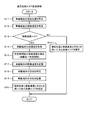
- FIG. 2 is a flowchart showing the acceleration storage process.
- FIG. 3 is a flowchart showing the self-hazardous area setting process.
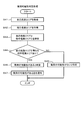
- FIG. 4 is a flowchart showing the partner danger area setting process.
- FIG. 5 is a flowchart showing a collision possibility determination process.
- FIG. 6A is a diagram showing a self-hazardous area set by the in-vehicle terminal
- FIG. 6B is a diagram showing a self-hazardous area set by the in-vehicle terminal
- FIG. 6A is a diagram showing a self-hazardous area set by the in-vehicle terminal
- FIG. 6B is a diagram showing a self-hazardous area set by the in-vehicle terminal
- FIG. 6A is a diagram showing a self-hazardous area set by the in-vehicle terminal
- FIG. 6B is a diagram
- FIG. 6C is a diagram showing a self-hazardous area set by the in-vehicle terminal
- FIG. 6D is a diagram showing a self-hazardous area set by the in-vehicle terminal
- FIG. 7A is a diagram showing a partner danger area set by the in-vehicle terminal
- FIG. 7B is a diagram showing a partner danger area set by the in-vehicle terminal
- FIG. 7C is a diagram showing the partner danger area set by the in-vehicle terminal
- FIG. 7D is a diagram showing a partner danger area set by the in-vehicle terminal
- FIG. 8 is a diagram showing the positional relationship between the vehicle and the pedestrian
- FIG. 8 is a diagram showing the positional relationship between the vehicle and the pedestrian
- FIG. 9 is a diagram showing the positional relationship between the vehicle and the pedestrian
- FIG. 10 is a diagram showing the positional relationship between the vehicle and the pedestrian
- FIG. 11 is a diagram showing the positional relationship between the vehicle and the pedestrian
- FIG. 12A is a diagram showing a self-hazardous area set by the in-vehicle terminal
- FIG. 12B is a diagram showing a self-hazardous area set by the in-vehicle terminal
- FIG. 12C is a diagram showing a self-hazardous area set by the in-vehicle terminal
- FIG. 12D is a diagram showing a self-risk area set by the in-vehicle terminal
- FIG. 12A is a diagram showing a self-hazardous area set by the in-vehicle terminal
- FIG. 12B is a diagram showing a self-hazardous area set by the in-vehicle terminal
- FIG. 12C is a diagram showing a self-hazardous area set by the in-
- FIG. 13A is a diagram showing a self-hazardous area set by the in-vehicle terminal
- FIG. 13B is a diagram showing a self-hazardous area set by the in-vehicle terminal
- FIG. 13C is a diagram showing a self-hazardous area set by the in-vehicle terminal
- FIG. 13D is a diagram showing a self-hazardous area set by the in-vehicle terminal
- FIG. 14 is a diagram showing a positional relationship between the vehicle and the pedestrian
- FIG. 15 is a diagram illustrating a positional relationship between a vehicle and a pedestrian.
- the collision determination system 1 includes an in-vehicle terminal 2 (corresponding to a first collision determination terminal, a collision determination terminal, and a partner terminal) mounted on a vehicle and a pedestrian terminal 3 carried by a pedestrian. (Corresponding to a second collision determination terminal, a collision determination terminal, and a counterpart terminal) are configured to be able to communicate with each other.
- the relationship between the in-vehicle terminal 2 and the pedestrian terminal 3 is an unspecified number, and the unspecified number of the in-vehicle terminals 2 and the unspecified number of pedestrian terminals 3 are configured to be able to communicate with each other.
- the in-vehicle terminal 2 may be a dedicated terminal that performs collision determination.
- the in-vehicle terminal 2 may be a terminal that also has other functions such as a navigation function and an audio function, for example, and may have a configuration in which a collision determination function is incorporated in the navigation terminal and the audio terminal.
- the pedestrian terminal 3 may be a dedicated terminal that performs collision determination.
- the pedestrian terminal 3 may be a terminal that also has other functions such as a telephone function and a schedule management function, for example, and a collision determination function is incorporated in a multi-function mobile phone terminal called a smartphone. It may be configured.
- the in-vehicle terminal 2 includes a control unit 21, a wireless communication unit 22, a GNSS (Global Navigation Satellite System) positioning unit 23, a sensor signal input unit 24, a storage unit 25, and a notification unit 26.
- the control unit 21 includes a microcomputer having a CPU (Central Processing Unit), a ROM (Read Only Memory), a RAM (Random Access Memory), and an I / O (Input / Output).
- the control unit 21 executes processing corresponding to the computer program by executing the computer program stored in the non-transitional tangible recording medium, and controls the overall operation of the in-vehicle terminal 2.
- the wireless communication unit 22 performs wireless communication with the pedestrian terminal 3.
- the wireless communication unit 22 may perform wireless communication with the pedestrian terminal 3 via a wireless base station (not shown), or perform wireless communication with the pedestrian terminal 3 without passing through the wireless base station. May be.
- the GNSS positioning unit 23 extracts various parameters from the GNSS signal received from the satellite, calculates the current position using the extracted various parameters, and outputs the calculated current position to the control unit 21.
- the sensor signal input unit 24 inputs sensor signals from a speed sensor 27, an acceleration sensor 28, and a direction sensor 29 that are mounted on the vehicle separately from the in-vehicle terminal 2.
- the sensor signal input unit 24 inputs a speed signal indicating the moving speed of the in-vehicle terminal 2 (that is, the traveling speed of the vehicle) from the speed sensor 27 and inputs an acceleration signal indicating the acceleration of the in-vehicle terminal 2 from the acceleration sensor 28. Then, an orientation signal indicating the orientation of the in-vehicle terminal 2 is input from the orientation sensor 29.
- the storage unit 25 has a storage area for storing sensor values specified by various sensor signals input from the various sensors 27 to 29 to the sensor signal input unit 24. That is, the storage unit 25 stores a speed storage area that stores the moving speed specified by the speed signal, an acceleration storage area that stores the acceleration specified by the acceleration signal, and an azimuth storage that stores the azimuth specified by the azimuth signal. And having a region.
- the notification command signal is input from the control unit 21, the notification unit 26 notifies the user of notification information indicating that there is a possibility of a collision. If the notification unit 26 includes a display unit, a display message or a warning screen indicating that there is a possibility of a collision is displayed. If the notification part 26 is comprised from the audio
- the control unit 21 includes a self-hazardous area setting unit 21a (corresponding to a first dangerous area setting unit), an opponent dangerous area setting unit 21b (corresponding to a second dangerous area setting unit), a determination unit 21c, and a notification control unit 21d. And have.
- the self-hazardous area setting unit 21a sets an area where the in-vehicle terminal 2 can move after a predetermined time from the current position as a self-hazardous area (corresponding to a first danger area).
- the self-hazardous area setting unit 21a includes the current position calculated by the GNSS positioning unit 23, The self-hazardous area is set using the moving speed specified by the speed signal and the direction specified by the direction signal.
- the self-hazardous area setting unit 21a calculates the moving speed using the acceleration specified by the acceleration signal, and GNSS The self-risk area is set using the current position calculated by the positioning unit 23, the moving speed calculated using the acceleration, and the direction specified by the direction signal.
- the opponent danger area setting unit 21b sets an area where the pedestrian terminal 3 can move after a predetermined time from the current position as an opponent danger area (corresponding to a second danger area).
- the partner danger area setting unit 21b determines the current position, moving speed, and direction of the pedestrian terminal 3. Use to set the opponent danger area.
- the partner danger area setting unit 21 b calculates the movement speed using the acceleration of the pedestrian terminal 3, The partner danger area is set using the current position of the pedestrian terminal 3, the moving speed calculated using the acceleration, and the direction of the pedestrian terminal 3.
- the determination unit 21c determines whether or not the self danger area and the partner danger area overlap, and determines the possibility of collision between the vehicle and the pedestrian (that is, danger). The determination unit 21c determines that the self-danger area and the partner danger area overlap if at least a part of the self-danger area overlaps at least a part of the partner danger area, and the vehicle and the pedestrian may collide with each other. It is determined that there is.
- the notification control unit 21d outputs the notification command signal described above to the notification unit 26, and notifies the notification information that there is a possibility of collision. 26 to notify.
- the pedestrian terminal 3 has basically the same configuration as the in-vehicle terminal 2.
- the pedestrian terminal 3 includes a control unit 31, a wireless communication unit 32, a GNSS positioning unit 33, a sensor signal input unit 34, a storage unit 35, and a notification unit 36.
- the control unit 31 includes a microcomputer having a CPU, ROM, RAM, and I / O.
- the control unit 31 executes processing corresponding to the computer program by executing the computer program stored in the non-transitional tangible recording medium, and controls the overall operation of the pedestrian terminal 3.
- the wireless communication unit 32 performs wireless communication with the in-vehicle terminal 2.
- the wireless communication unit 32 may perform wireless communication with the in-vehicle terminal 2 via a wireless base station (not shown), or may perform wireless communication with the in-vehicle terminal 2 without passing through the wireless base station. good.
- the GNSS positioning unit 33 extracts various parameters from the GNSS signal received from the satellite, calculates the current position using the extracted parameters, and outputs the calculated current position to the control unit 31.
- the sensor signal input unit 34 inputs sensor signals from a speed sensor 37, an acceleration sensor 38, and an orientation sensor 39 that are mounted on the pedestrian terminal 3.
- the sensor signal input unit 34 inputs a speed signal indicating the moving speed of the pedestrian terminal 3 (that is, the walking speed of the pedestrian) from the speed sensor 37, and receives an acceleration signal indicating the acceleration of the pedestrian terminal 3 as the acceleration sensor 38. And an azimuth signal indicating the azimuth of the pedestrian terminal 3 is inputted from the azimuth sensor 39.
- the storage unit 35 has a storage area for storing sensor values specified by various sensor signals input from the various sensors 37 to 39 to the sensor signal input unit 34. That is, the storage unit 35 stores a speed storage area that stores a moving speed specified by a speed signal, an acceleration storage area that stores an acceleration specified by an acceleration signal, and an azimuth storage that stores an azimuth specified by an azimuth signal. And having a region.
- the notification command signal is input from the control unit 31, the notification unit 36 notifies the user of notification information indicating that there is a possibility of a collision. If the notification part 36 is comprised from the display part, the display message and warning screen to the effect of the possibility of a collision will be displayed. If the notification part 36 is comprised from the audio
- the control unit 31 includes a self-risk area setting unit 31a (corresponding to a second risk area setting unit) and a partner risk area setting unit 31b (corresponding to the first risk area setting unit). Equivalent), a determination unit 31c, and a notification control unit 31d.
- the self-hazardous area setting unit 31a sets an area in which the pedestrian terminal 3 can move after a predetermined time from the current position as a self-hazardous area (corresponding to a first danger area). When the moving speed of the pedestrian terminal 3 exceeds “0” (that is, when the pedestrian is walking), the self-hazardous area setting unit 31a determines the current position and speed calculated by the GNSS positioning unit 33.
- the self-hazardous area is set using the moving speed specified by the signal and the direction specified by the direction signal.
- the moving speed of the pedestrian terminal 3 is “0” (that is, when the pedestrian is stopped)
- the self-hazardous area setting unit 31a calculates the moving speed using the acceleration specified by the acceleration signal.
- the self-risk area is set using the current position calculated by the GNSS positioning unit 23, the moving speed calculated using the acceleration, and the direction specified by the direction signal.
- the partner danger area setting unit 31b sets an area where the in-vehicle terminal 2 can move after a predetermined time from the current position as a partner danger area (corresponding to a second danger area).
- a partner danger area corresponding to a second danger area.
- the partner danger area setting unit 31 b uses the current position, the moving speed, and the direction of the in-vehicle terminal 2. Set the partner danger area.
- the partner danger area setting unit 31b calculates the moving speed using the acceleration of the in-vehicle terminal 2, and the in-vehicle terminal 2 The partner danger area is set using the current position, the moving speed calculated using the acceleration, and the direction of the in-vehicle terminal 2.
- the determination unit 31c determines whether or not the self danger area and the partner danger area overlap, and determines the possibility that the vehicle and the pedestrian collide.
- the determination unit 31c determines that the self-danger area overlaps with the partner danger area if at least a part of the self-danger area overlaps with at least a part of the partner danger area, and the vehicle and the pedestrian may collide with each other. It is determined that there is.
- the notification control unit 31d outputs the notification command signal described above to the notification unit 36, and notifies the notification unit that there is a possibility of collision. 36 to notify.
- the control unit 21 of the in-vehicle terminal 2 and the control unit 31 of the pedestrian terminal 3 perform an acceleration storage process, a self danger area setting process, a partner danger area setting process, and a collision possibility determination process, respectively, in relation to the present disclosure.
- each process will be described sequentially.
- the case where the controller 21 determines the possibility of collision between the vehicle and the pedestrian will be described as a representative of the controller 21.
- the control unit 21 determines the possibility that the vehicle and the pedestrian collide
- the in-vehicle terminal 2 is treated as a self terminal and the pedestrian terminal 3 is treated as a partner terminal.
- control unit 31 determines the possibility that the vehicle and the pedestrian collide
- the pedestrian terminal 3 is treated as a self terminal and the in-vehicle terminal 2 is treated as a counterpart terminal.
- the control unit 21 monitors whether or not a start condition for each process is satisfied. When it is determined that any process start condition is satisfied, the control unit 21 starts a process that satisfies the start condition.
- (1) Acceleration storage process When the control unit 21 determines that the acceleration storage process start condition is satisfied, the control unit 21 starts the acceleration storage process.
- the control unit 21 specifies the moving speed of the in-vehicle terminal 2 based on the speed signal input from the speed sensor 27 to the sensor signal input unit 24 (S1), and whether the moving speed is “0”. It is determined whether or not (S2).
- S2: NO the control unit 21 ends the acceleration storage process and waits for the start condition of the next acceleration storage process to be satisfied.
- the control unit 21 When determining that the moving speed is “0” (S2: YES), the control unit 21 specifies the acceleration of the in-vehicle terminal 2 from the acceleration signal input from the acceleration sensor 28 to the sensor signal input unit 24 (S3). It is determined whether or not the acceleration exceeds “0” (S4). When the control unit 21 determines that the acceleration does not exceed “0” (S4: NO), the control unit 21 ends the acceleration storage process, and waits for establishment of a start condition for the next acceleration storage process.
- the control unit 21 When determining that the acceleration exceeds “0” (S4: YES), the control unit 21 stores the acceleration in the acceleration storage area (S5), ends the acceleration storage process, and starts the next acceleration storage process. Wait for the establishment of. In this case, if the acceleration is already stored in the acceleration storage area, the control unit 21 deletes the stored acceleration and stores the acceleration specified at the current timing (that is, the latest acceleration). That is, the control unit 21 updates the acceleration every time it is determined that the moving speed is “0” and the acceleration exceeds “0”. The controller 21 continues to update the acceleration when the vehicle starts to travel from the stop by performing the acceleration storage process described above.
- the control unit 21 determines that the start condition of the self-hazardous area setting process (corresponding to the first procedure) is satisfied, the control part 21 starts the self-hazardous area setting process.
- the control unit 21 inputs the current position from the GNSS positioning unit 23 to identify the current position of the in-vehicle terminal 2 (S11).
- the control unit 21 specifies the moving speed of the in-vehicle terminal 2 based on the speed signal input from the speed sensor 27 to the sensor signal input unit 24 (S12), and determines whether the moving speed is “0” (S13). ).
- the control unit 21 determines that the moving speed is not “0” (S13: NO)
- the current position calculated by the GNSS positioning unit 23, the moving speed specified by the speed signal, and the direction specified by the direction signal Are used to set the self-hazardous area (S14)
- the self-hazardous area setting process is terminated, and the start of the next self-hazardous area setting process is awaited.
- the control unit 21 determines that the moving speed (that is, the traveling speed of the vehicle) is not “0”, the control unit 21 specifies the traveling direction of the vehicle based on the change with time of the current position (that is, the moving direction). As shown in FIG. 6C, the self-hazardous area M is set according to the moving speed and the direction. That is, when the moving speed is relatively fast, the control unit 21 has a relatively high straightness of the vehicle. Therefore, the control unit 21 sets the self-hazardous area M that is relatively long in the traveling direction of the vehicle and relatively narrow in the vehicle width direction. Set.
- the control unit 21 when the moving speed is relatively low, the control unit 21 has a relatively low self-risk area M that is relatively short in the vehicle traveling direction and relatively wide in the vehicle width direction because the straight traveling performance of the vehicle is relatively low.
- the control unit 21 sets the self-hazardous area M in a shape based on a sector. 6A to 6C exemplify the case where the vehicle is moving forward, that is, the case where the front side of the vehicle is the traveling direction, but the case where the vehicle is moving backward, that is, the rear side of the vehicle is the traveling direction. In some cases, the control unit 21 sets a self-hazardous area M behind the vehicle.
- the control unit 21 when determining that the moving speed is “0” (S13: YES), the control unit 21 reads and acquires the acceleration (that is, the latest acceleration) stored by the acceleration storing process (S15). The control unit 21 multiplies the acquired acceleration by a predetermined time, calculates the moving speed after the predetermined time (S16), and stores the calculated moving speed in the speed storage area (S17). That is, when the control unit 21 determines that the movement speed is “0”, the control unit 21 multiplies the acceleration at the start of the previous movement by a predetermined time, and calculates the movement speed after the predetermined time at the start of the current movement. Predict.
- the control unit 21 erases the stored moving speed and stores the moving speed calculated at the current timing (that is, the latest moving speed). To do. That is, the control unit 21 updates the moving speed every time it is determined that the moving speed is “0”.
- the control unit 21 specifies the direction of the in-vehicle terminal 2 based on the direction signal input from the direction sensor 29 to the sensor signal input unit 24 (S18), and stores the direction in the direction storage area (S19). In this case, if the azimuth is already stored in the azimuth storage area, the control unit 21 deletes the stored azimuth and stores the azimuth specified at the current timing (that is, the latest azimuth). That is, the control unit 21 updates the direction every time it determines that the moving speed is “0”. Then, the control unit 21 sets a self-risk area using the current position calculated by the GNSS positioning unit 23, the moving speed calculated using the acceleration, and the direction specified by the direction signal (S20). The self-hazardous area setting process is terminated, and the process waits for the start condition of the next self-hazardous area setting process to be satisfied.
- the control unit 21 sets the self-hazardous area M over the entire periphery of the vehicle as shown in FIG. 6D. Set. In this case, the control unit 21 sets the size (that is, the area) of the self-hazardous area M wider as the moving speed calculated using the acceleration is higher. That is, the control unit 21 sets the size of the self-hazardous area M wider as the acceleration or the predetermined time is larger. The control unit 21 sets the self-hazardous area where the vehicle is predicted to reach from the current position regardless of whether the vehicle is running or stopped by performing the self-hazardous area setting process described above. .
- the control part 21 will start a partner dangerous area setting process.
- the control unit 21 acquires position information of the partner terminal (S21). That is, the control unit 21 receives the position information of the pedestrian terminal 3 transmitted from the pedestrian terminal 3 that is the target of the collision determination by the wireless communication unit 22, and thereby the position information of the pedestrian terminal 3 that is the counterpart terminal. To get. In this case, the control unit 21 may receive position information unilaterally transmitted from the pedestrian terminal 3 by the wireless communication unit 22.
- control unit 21 transmits a position information transmission request to the pedestrian terminal 3 so that the wireless communication unit 22 receives the position information transmitted from the pedestrian terminal 3 as a transmission response to the transmission request. good.
- the position information of the pedestrian terminal 3 includes the current position, moving speed, acceleration, and direction of the pedestrian terminal 3.
- the control unit 21 specifies the current position of the pedestrian terminal 3 based on the position information of the pedestrian terminal 3 (S22).
- the control unit 21 specifies the moving speed of the pedestrian terminal 3 from the position information of the pedestrian terminal 3 (S23), and determines whether the moving speed is “0” (S24).
- S24 determines whether the moving speed is “0” (S24).
- the control unit 21 sets a partner danger area using the current position, the moving speed, and the direction specified by the position information of the pedestrian terminal 3 ( S25), the partner danger area setting process is terminated, and the start of the next partner danger area setting process is awaited.
- the control unit 21 determines that the moving speed (that is, the walking speed of the pedestrian) is not “0”, the control unit 21 determines the pedestrian's movement direction based on the moving direction of the current position specified by the position information of the pedestrian terminal 3.
- the traveling direction is specified, and as shown in FIGS. 7A and 7B, the partner danger area N is set according to the moving speed and the direction specified by the position information of the pedestrian terminal 3. That is, when the moving speed is relatively fast, the control unit 21 is relatively long in the pedestrian direction and relatively narrow in the left-right direction of the pedestrian because the pedestrian is relatively straight. Danger area N is set.
- the control unit 21 when the moving speed is relatively slow, the control unit 21 is relatively short in the pedestrian direction and relatively wide in the left-right direction of the pedestrian because the pedestrian's straightness is relatively low. Danger area N is set. In addition, the control part 21 sets the other party dangerous area N in the shape based on a fan shape.
- the control unit 21 determines that the moving speed is “0” (S24: YES)
- the control unit 21 specifies the acceleration of the pedestrian terminal 3 based on the position information of the pedestrian terminal 3 (S26).
- the acceleration is multiplied by a predetermined time, the moving speed after the predetermined time is calculated (S27), and the calculated moving speed is stored in the speed storage area (S28). That is, when the control unit 21 determines that the movement speed is “0”, the control unit 21 multiplies the acceleration at the start of the previous movement by a predetermined time, and calculates the movement speed after the predetermined time at the start of the current movement. Predict.
- the control unit 21 erases the stored moving speed and stores the moving speed calculated at the current timing (that is, the latest moving speed). To do. That is, the control unit 21 updates the moving speed every time it is determined that the moving speed is “0”.
- the control unit 21 specifies the azimuth of the pedestrian terminal 3 from the position information of the pedestrian terminal 3 (S29), and stores the azimuth in the azimuth storage area (S30). In this case, if the azimuth is already stored in the azimuth storage area, the control unit 21 deletes the stored azimuth and stores the azimuth specified at the current timing (that is, the latest azimuth). That is, the control unit 21 updates the direction every time it determines that the moving speed is “0”. Then, the control unit 21 calculates the movement speed using the acceleration, and uses the current position specified by the position information of the pedestrian terminal 3, the movement speed calculated using the acceleration, and the position information of the pedestrian terminal 3. The partner danger area is set using the specified direction (S31), the partner danger area setting process is terminated, and the start of the next partner danger area setting process is awaited.
- the controller 21 determines that the pedestrian's direction of travel is undecided, and as shown in FIG. 7C and FIG.
- the partner danger area N is set around the left and right sides of about 90 degrees (ie, in a semicircular shape).
- the control unit 21 sets the size of the partner danger area N wider (that is, the longer the radius of the sector) as the moving speed calculated using the acceleration is larger. That is, the control unit 21 sets the size of the opponent danger area N wider as the acceleration or the predetermined time is larger. For example, if the pedestrian tends to relatively widen the first few steps when the pedestrian starts walking, the control unit 21 sets the size of the opponent danger area N relatively wide.
- the control unit 21 determines the partner danger area that the pedestrian is predicted to reach from the current position regardless of whether the pedestrian is walking or stopped.
- the control unit 21 may set the opponent danger area N in a shape different from the semicircular shape. That is, assuming a situation in which a pedestrian suddenly starts moving forward or only to the left and right in a forward-facing situation, the control unit 21 may set the danger area N in a semicircular shape as described above. Assuming a situation where the person suddenly starts moving forward only in a forward-facing situation, the control unit 21 may set the danger area N at an angle smaller than 180 degrees. Further, assuming a situation where the pedestrian starts to suddenly move in all directions in a forward-facing situation, the control unit 21 may set the danger area N in a circular shape.
- the control unit 21 determines that the start condition of the collision possibility determination process is satisfied, the control unit 21 starts the collision possibility determination process.
- the control unit 21 acquires the self-danger area specified by the self-danger area setting process (S41), and acquires the partner danger area specified by the partner danger area setting process (S42).
- the control unit 21 collates the acquired self-hazardous area with the partner-hazardous area (S43), and determines whether there is an opponent-hazardous area that overlaps with the self-hazardous area (S44, corresponding to the third procedure).
- the control unit 21 specifies that there is no partner danger area that overlaps with the self danger area (S34: NO), the control unit 21 specifies that the vehicle and the pedestrian do not collide (S35), and performs the collision possibility determination process. Ends and waits for establishment of the start condition of the next collision possibility determination process. That is, as shown in FIG. 8, the vehicle A on which the in-vehicle terminal 2 is mounted is running, the pedestrians b and c existing around the vehicle A are walking, and the pedestrians a and d are stopped. In the middle situation, the control unit 21 sets a self-hazardous area MA for the vehicle A, and sets opponent danger areas Na to Nd for the pedestrians a to d, respectively. If the control unit 21 determines that none of the partner danger areas Na to Nd overlaps with the self danger area MA, it specifies that there is no possibility of a collision.
- the control unit 21 specifies that there is a partner danger area that overlaps with the self danger area (S34: YES)
- the control unit 21 specifies that the vehicle and the pedestrian may collide (S36). That is, as shown in FIG. 9, the vehicle A on which the in-vehicle terminal 2 is mounted is traveling, the pedestrians b and c existing around the vehicle A are walking, and the pedestrians a and d are stopped.
- the control unit 21 determines that Na of the opponent dangerous areas Na to Nd overlaps with the self-hazardous area MA, it determines that there is a possibility of a collision. 8 and FIG.
- control unit 21 changes the direction of the body (that is, the azimuth) from the direction other than the road to the direction of the road. If person a attempts to cross the road, it identifies that there is a possibility of a collision.
- the control unit 21 outputs a notification command signal to the notification unit 26, notifies the user of notification information indicating that there is a possibility of collision (S37, corresponding to the fourth procedure), and determines the possibility of collision.
- the process ends, and the process waits for establishment of a start condition for the next collision possibility determination process.
- the control unit 21 may simply notify notification information such as “please pay attention to pedestrians” indicating that there is a possibility of a collision.
- the control unit 21 specifies whether the part where the opponent danger area and the self-danger area overlap is on the left or right with reference to the traveling direction of the vehicle, and there is a possibility of a collision on the left or right of the traveling direction.
- the control unit 21 may notify notification information such as “please pay attention to the pedestrian on the right front”.
- the control unit 21 calculates the distance from the current position of the vehicle to the current position of the pedestrian terminal 3 of the pedestrian that has been identified as having the possibility of a collision, so that the approximate distance to the point where the collision is likely to occur is calculated. You may notify the correct distance. That is, for example, when the distance is calculated as 100 meters, the control unit 21 may notify notification information such as “Please beware of a pedestrian ahead 100 meters ahead”.
- the unit 21 may notify the pedestrian who is the user of the pedestrian terminal 3 of the notification information by transmitting the notification information to the pedestrian terminal 3 of the pedestrian who has identified the possibility of the collision.
- the control unit 31 may simply notify notification information such as “Please pay attention to the vehicle” indicating that there is a possibility of a collision.
- the control unit 31 determines the direction in which the vehicle arrives.
- the control unit 31 when it is determined that the vehicle is coming from the left side, the control unit 31 notifies the notification information such as “Please pay attention to the vehicle from the left side”. Also good.
- the control unit 31 calculates the distance as described above. For example, when the distance is calculated to be 100 meters, the notification information such as “Please pay attention to the vehicle from the left side 100 meters ahead” is displayed. You may be notified.
- the self danger area is set, the partner danger area is set, and the self danger area and the partner danger area are collated, but without setting the partner danger area
- the self danger area set by the pedestrian terminal 3 may be acquired from the pedestrian terminal 3 as a partner danger area, and the self danger area and the partner danger area obtained from the pedestrian terminal 3 may be collated. That is, each of the in-vehicle terminal 2 and the pedestrian terminal 3 sets a self-risk area, acquires the self-risk area set by the partner terminal from the partner terminal as the partner risk area, and collates the self-danger area with the partner risk area. Also good.
- the configuration for determining the possibility of colliding with a pedestrian as viewed from the vehicle has been described above, but the configuration for determining the possibility of colliding with a vehicle when viewed from the pedestrian may be used.
- the pedestrian e carrying the pedestrian terminal 3 is stopped with his body facing in a direction other than the road, and vehicles B and C existing around the pedestrian e are traveling.
- the control unit 31 sets a self-hazardous area Ne for the pedestrian e and sets an opponent danger area MB and MC for the vehicles B and C, respectively.
- the control unit 31 determines that neither the partner danger area MB or MC overlaps the self danger area Ne, the control part 31 identifies that there is no possibility of a collision.
- the pedestrian e who is carrying the pedestrian terminal 3 is stopped with his body facing the road, and the vehicles B and C existing around the pedestrian e are traveling.
- the control unit 31 determines that the MB of the opponent dangerous areas MB and MC overlaps the self dangerous area Ne, the controller 31 specifies that there is a possibility of a collision.
- the pedestrian e who has stopped has changed the body direction (that is, the azimuth) from the direction other than the road to the direction of the road. Specifies that there is a possibility of collision if the pedestrian e attempts to cross the road.
- control unit 21 sets the self-hazardous area M with a shape based on a sector
- the configuration may be such that the self-hazardous area M is set with a shape different from the shape based on a sector.
- the control unit 21 may be configured to set the self-hazardous area M in a shape based on a quadrangle.
- the control unit 21 may be configured to set the self-hazardous area M in a shape in which a plurality of shapes based on a sector shape are combined. That is, the control unit 21 may set the self-hazardous area M in any shape.
- the collision determination system 1 for each of the in-vehicle terminal 2 and the pedestrian terminal 3, an area that can be moved after a predetermined time from the current position is set as a dangerous area, and it is determined whether or not the dangerous areas overlap. Judgment of the possibility of collision. Thereby, even if it is a case where the stopped pedestrian begins to act suddenly, the possibility that a vehicle and a pedestrian will collide can be determined with sufficient accuracy.
- the control unit 21 sets the self-hazardous area M
- the self-hazardous area M when the moving speed is relatively slow, the self-hazardous area M is set to be relatively short in the vehicle traveling direction and relatively wide in the vehicle width direction.
- the self-hazardous area M is also set on the left and right sides of the vehicle (that is, in the vehicle width direction).
- the control unit 21 determines the overlap between the self-hazardous area MD and the partner-hazardous area Ng, thereby accurately determining the possibility of a collision. Can be judged well. As shown in FIG. 15, also for a pedestrian h that is stopped at a driver's blind spot across a two-wheeled vehicle such as a bicycle, the control unit 21 determines the overlap between the self-hazardous area MD and the partner-hazardous area Nh. Thus, the possibility of collision can be accurately determined.
- the configuration in which the current position is calculated using the GNSS signal received from the satellite is illustrated, for example, a configuration in which the current position is calculated using a communication radio wave of WiFi (Wireless Fidelity) may be used.
- the configuration of calculating the moving speed using the latest acceleration when the moving speed is “0” is exemplified, but the average value of the accelerations of the past multiple times is calculated, and the movement is performed using the calculated average value.
- a configuration for calculating the speed may be used.
- the configuration in which the vehicle and the pedestrian are applied as the determination target is illustrated, a configuration in which only the vehicle or only the pedestrian is applied, or a configuration in which the possibility of collision between the vehicles or the pedestrians may be determined. If it is the structure which applies only a vehicle, it is effective in the situation where there are many opportunities to drive
Landscapes
- Physics & Mathematics (AREA)
- General Physics & Mathematics (AREA)
- Engineering & Computer Science (AREA)
- Mechanical Engineering (AREA)
- Computer Networks & Wireless Communication (AREA)
- Signal Processing (AREA)
- Radar, Positioning & Navigation (AREA)
- Remote Sensing (AREA)
- Traffic Control Systems (AREA)
Abstract
車載端末(2)は、自己が現在位置から所定時間後に移動可能なエリアを自己危険エリアとして設定する自己危険エリア設定部(21a)と、歩行者端末(3)が現在位置から所定時間後に移動可能なエリアを相手危険エリアとして設定する相手危険エリア設定部(21b)と、自己危険エリアと相手危険エリアとが重なるか否かを判定し、車両と歩行者とが衝突する可能性を判定する判定部(21c)と、衝突の可能性があると特定されると、通知情報を通知部(26)から通知させる通知制御部(21d)とを有する。
Description
本出願は、2015年10月15日に出願された日本出願番号2015-203695号に基づくもので、ここにその記載内容を援用する。
本開示は、衝突判定システム、衝突判定端末及びコンピュータプログラムに関する。
例えば歩行者と車両とが衝突する可能性を判定する衝突判定システムとして、歩行者に携帯されている歩行者端末の現在位置と車両に搭載されている車載端末の現在位置とを用いて判定する構成がある。例えば特許文献1には、車載端末において、自己の現在位置を用いて危険エリアを設定し、その設定した危険エリア内に歩行者端末が存在しているか否かを判定し、衝突の可能性を判定する構成が記載されている。又、特許文献2及び3には、車載端末において、歩行者端末の現在位置を用いて歩行者の移動経路を予測し、自己の移動経路と歩行者の移動経路との位置関係を判定し、衝突の可能性を判定する構成が記載されている。
歩行者は道路上で常に歩行しているとは限らず停止している場合がある。そして、停止している歩行者が道路横断や飛び出し(例えば落し物を回収する等の行為)等のタイミングを見計らっていると、その停止している歩行者が車両の往来が途切れたタイミングで道路横断や飛び出し等を行う場合がある。このように停止している歩行者が突発的に行動し始めることがあるという事情から、移動している歩行者のみならず停止している歩行者をも判定対象として衝突の可能性を判定するシステムが望まれている。特許文献1では、歩行者の移動方向や移動速度に関係なく危険エリア内に歩行者端末が存在しているか否かを判定する構成であるので、例えば車両の進行方向と同じ方向に歩道を歩行している歩行者までも衝突の可能性があると判定してしまう。又、特許文献2及び3では、歩行者の移動経路を予測する構成であるので、移動している歩行者のみが判定対象となり、停止している歩行者は判定対象から除外されてしまう。
本開示は、停止している例えば歩行者等の判定対象の衝突の可能性を精度良く判定することができる衝突判定システム、衝突判定端末及びコンピュータプログラムを提供することにある。
本開示の態様において、第1危険エリア設定部は、第1判定対象に設けられている第1衝突判定端末が現在位置から所定時間後に移動可能なエリアを第1危険エリアとして設定する。第2危険エリア設定部は、第2判定対象に設けられている第2衝突判定端末が現在位置から所定時間後に移動可能なエリアを第2危険エリアとして設定する。判定部は、第1危険エリアと第2危険エリアとが重なるか否かを判定し、第1判定対象と第2判定対象とが衝突する可能性を判定する。そして、第1判定対象と第2判定対象とが衝突する可能性があると判定部により特定されると、通知制御部は、衝突の可能性がある旨の通知情報を通知部から通知させる。
第1衝突判定端末と第2衝突判定端末とのそれぞれについて現在位置から所定時間後に移動可能なエリアを危険エリアとして設定し、危険エリアが重なるか否かを判定し、第1判定対象と第2判定対象とが衝突する可能性を判定するようにした。第1判定対象及び第2判定対象のうち少なくとも一方が停止しており、その停止している判定対象が移動し始めたとしても、それら判定対象同士の衝突の可能性を精度良く判定することができる。
本開示についての上記目的及びその他の目的、特徴や利点は、添付の図面を参照しながら下記の詳細な記述により、より明確になる。その図面は、
図1は、本開示の一実施形態の全体構成を示す機能ブロック図であり、
図2は、加速度記憶処理を示すフローチャートであり、
図3は、自己危険エリア設定処理を示すフローチャートであり、
図4は、相手危険エリア設定処理を示すフローチャートであり、
図5は、衝突可能性判定処理を示すフローチャートであり、
図6Aは、車載端末が設定する自己危険エリアを示す図であり、
図6Bは、車載端末が設定する自己危険エリアを示す図であり、
図6Cは、車載端末が設定する自己危険エリアを示す図であり、
図6Dは、車載端末が設定する自己危険エリアを示す図であり、
図7Aは、車載端末が設定する相手危険エリアを示す図であり、
図7Bは、車載端末が設定する相手危険エリアを示す図であり、
図7Cは、車載端末が設定する相手危険エリアを示す図であり、
図7Dは、車載端末が設定する相手危険エリアを示す図であり、
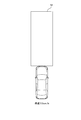
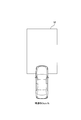
図8は、車両と歩行者との位置関係を示す図であり、
図9は、車両と歩行者との位置関係を示す図であり、
図10は、車両と歩行者との位置関係を示す図であり、
図11は、車両と歩行者との位置関係を示す図であり、
図12Aは、車載端末が設定する自己危険エリアを示す図であり、
図12Bは、車載端末が設定する自己危険エリアを示す図であり、
図12Cは、車載端末が設定する自己危険エリアを示す図であり、
図12Dは、車載端末が設定する自己危険エリアを示す図であり、
図13Aは、車載端末が設定する自己危険エリアを示す図であり、
図13Bは、車載端末が設定する自己危険エリアを示す図であり、
図13Cは、車載端末が設定する自己危険エリアを示す図であり、
図13Dは、車載端末が設定する自己危険エリアを示す図であり、
図14は、車両と歩行者との位置関係を示す図であり、
図15は、車両と歩行者との位置関係を示す図である。
以下、本開示を、車両及び歩行者を判定対象とし、車両と歩行者とが衝突する可能性を判定する衝突判定システムに適用した一実施形態について図面を参照して説明する。
図1に示すように、衝突判定システム1は、車両に搭載されている車載端末2(第1衝突判定端末、衝突判定端末、相手端末に相当)と歩行者に携帯されている歩行者端末3(第2衝突判定端末、衝突判定端末、相手端末に相当)とが通信可能に構成されている。車載端末2と歩行者端末3との関係は不特定多数同士の関係にあり、不特定多数の車載端末2と不特定多数の歩行者端末3とが通信可能に構成されている。車載端末2は、衝突判定を行う専用の端末でも良い。又、車載端末2は、例えばナビゲーション機能やオーディオ機能等の他の機能を兼用する端末でも良く、ナビゲーション端末やオーディオ端末等に衝突判定の機能が組み込まれている構成でも良い。歩行者端末3は、衝突判定を行う専用の端末でも良い。又、歩行者端末3は、例えば電話機能やスケジュール管理機能等の他の機能を兼用する端末でも良く、スマートフォンと称される多機能型の携帯電話端末等に衝突判定の機能が組み込まれている構成でも良い。
図1に示すように、衝突判定システム1は、車両に搭載されている車載端末2(第1衝突判定端末、衝突判定端末、相手端末に相当)と歩行者に携帯されている歩行者端末3(第2衝突判定端末、衝突判定端末、相手端末に相当)とが通信可能に構成されている。車載端末2と歩行者端末3との関係は不特定多数同士の関係にあり、不特定多数の車載端末2と不特定多数の歩行者端末3とが通信可能に構成されている。車載端末2は、衝突判定を行う専用の端末でも良い。又、車載端末2は、例えばナビゲーション機能やオーディオ機能等の他の機能を兼用する端末でも良く、ナビゲーション端末やオーディオ端末等に衝突判定の機能が組み込まれている構成でも良い。歩行者端末3は、衝突判定を行う専用の端末でも良い。又、歩行者端末3は、例えば電話機能やスケジュール管理機能等の他の機能を兼用する端末でも良く、スマートフォンと称される多機能型の携帯電話端末等に衝突判定の機能が組み込まれている構成でも良い。
車載端末2は、制御部21と、無線通信部22と、GNSS(Global Navigation Satellite System)測位部23と、センサ信号入力部24と、記憶部25と、通知部26とを有する。制御部21は、CPU(Central Processing Unit)、ROM(Read Only Memory)、RAM(Random Access Memory)及びI/O(Input/Output)を有するマイクロコンピュータにより構成されている。制御部21は、非遷移的実体的記録媒体に格納されているコンピュータプログラムを実行することで、コンピュータプログラムに対応する処理を実行し、車載端末2の動作全般を制御する。
無線通信部22は、歩行者端末3との間で無線通信を行う。無線通信部22は、図示しない無線基地局を介して歩行者端末3との間で無線通信を行っても良いし、無線基地局を介さずに歩行者端末3との間で無線通信を行っても良い。GNSS測位部23は、衛星から受信したGNSS信号から各種パラメータを抽出し、その抽出した各種パラメータを用いて現在位置を演算し、その演算した現在位置を制御部21に出力する。センサ信号入力部24は、車載端末2とは別に車両に搭載されている速度センサ27、加速度センサ28、方位センサ29からセンサ信号を入力する。即ち、センサ信号入力部24は、車載端末2の移動速度(即ち車両の走行速度)を示す速度信号を速度センサ27から入力し、車載端末2の加速度を示す加速度信号を加速度センサ28から入力し、車載端末2の方位を示す方位信号を方位センサ29から入力する。
記憶部25は、各種センサ27~29からセンサ信号入力部24に入力された各種センサ信号により特定されるセンサ値を記憶する記憶領域を有する。即ち、記憶部25は、速度信号により特定される移動速度を記憶する速度記憶領域と、加速度信号により特定される加速度を記憶する加速度記憶領域と、方位信号により特定される方位を記憶する方位記憶領域とを有する。通知部26は、制御部21から通知指令信号を入力すると、衝突の可能性がある旨を示す通知情報をユーザに対して通知する。通知部26が表示部から構成されていれば、衝突の可能性がある旨の表示メッセージや警告画面を表示する。通知部26が音声出力部から構成されていれば、衝突の可能性がある旨の音声ガイダンスや警告音を音声出力する。
制御部21は、自己危険エリア設定部21a(第1危険エリア設定部に相当)と、相手危険エリア設定部21b(第2危険エリア設定部に相当)と、判定部21cと、通知制御部21dとを有する。自己危険エリア設定部21aは、車載端末2が現在位置から所定時間後に移動可能なエリアを自己危険エリア(第1危険エリアに相当)として設定する。自己危険エリア設定部21aは、車載端末2の移動速度が「0」(零)を超えているとき(即ち車両が走行中のとき)には、GNSS測位部23により演算された現在位置と、速度信号により特定された移動速度と、方位信号により特定された方位とを用いて自己危険エリアを設定する。自己危険エリア設定部21aは、車載端末2の移動速度が「0」であるとき(即ち車両が停止中のとき)には、加速度信号により特定された加速度を用いて移動速度を演算し、GNSS測位部23により演算された現在位置と、その加速度を用いて演算した移動速度と、方位信号により特定された方位とを用いて自己危険エリアを設定する。
相手危険エリア設定部21bは、歩行者端末3が現在位置から所定時間後に移動可能なエリアを相手危険エリア(第2危険エリアに相当)として設定する。相手危険エリア設定部21bは、歩行者端末3の移動速度が「0」を超えているとき(即ち歩行者が歩行中のとき)には、歩行者端末3の現在位置と移動速度と方位とを用いて相手危険エリアを設定する。相手危険エリア設定部21bは、歩行者端末3の移動速度が「0」であるとき(即ち歩行者が停止中のとき)には、歩行者端末3の加速度を用いて移動速度を演算し、歩行者端末3の現在位置と、その加速度を用いて演算した移動速度と、歩行者端末3の方位とを用いて相手危険エリアを設定する。
判定部21cは、自己危険エリアと相手危険エリアとが重なるか否かを判定し、車両と歩行者とが衝突する可能性(即ち危険性)を判定する。判定部21cは、自己危険エリアの少なくとも一部と相手危険エリアの少なくとも一部とが重なれば、自己危険エリアと相手危険エリアとが重なると判定し、車両と歩行者とが衝突する可能性があると判定する。通知制御部21dは、車両と歩行者とが衝突する可能性があると判定されると、上記した通知指令信号を通知部26に出力し、衝突の可能性がある旨の通知情報を通知部26から通知させる。
歩行者端末3は、基本的に車載端末2と同様の構成である。歩行者端末3は、制御部31と、無線通信部32と、GNSS測位部33と、センサ信号入力部34と、記憶部35と、通知部36とを有する。制御部31は、CPU、ROM、RAM及びI/Oを有するマイクロコンピュータにより構成されている。制御部31は、非遷移的実体的記録媒体に格納されているコンピュータプログラムを実行することで、コンピュータプログラムに対応する処理を実行し、歩行者端末3の動作全般を制御する。
無線通信部32は、車載端末2との間で無線通信を行う。無線通信部32は、図示しない無線基地局を介して車載端末2との間で無線通信を行っても良いし、無線基地局を介さずに車載端末2との間で無線通信を行っても良い。GNSS測位部33は、衛星から受信したGNSS信号から各種パラメータを抽出し、その抽出した各種パラメータを用いて現在位置を演算し、その演算した現在位置を制御部31に出力する。センサ信号入力部34は、歩行者端末3に搭載されている速度センサ37、加速度センサ38、方位センサ39からセンサ信号を入力する。即ち、センサ信号入力部34は、歩行者端末3の移動速度(即ち歩行者の歩行速度)を示す速度信号を速度センサ37から入力し、歩行者端末3の加速度を示す加速度信号を加速度センサ38から入力し、歩行者端末3の方位を示す方位信号を方位センサ39から入力する。
記憶部35は、各種センサ37~39からセンサ信号入力部34に入力された各種センサ信号により特定されるセンサ値を記憶する記憶領域を有する。即ち、記憶部35は、速度信号により特定される移動速度を記憶する速度記憶領域と、加速度信号により特定される加速度を記憶する加速度記憶領域と、方位信号により特定される方位を記憶する方位記憶領域とを有する。通知部36は、制御部31から通知指令信号を入力すると、衝突の可能性がある旨を示す通知情報をユーザに対して通知する。通知部36が表示部から構成されていれば、衝突の可能性がある旨の表示メッセージや警告画面を表示する。通知部36が音声出力部から構成されていれば、衝突の可能性がある旨の音声ガイダンスや警告音を音声出力する。
制御部31は、上記した車載端末2の制御部21と同様に、自己危険エリア設定部31a(第2危険エリア設定部に相当)と、相手危険エリア設定部31b(第1危険エリア設定部に相当)と、判定部31cと、通知制御部31dとを有する。自己危険エリア設定部31aは、歩行者端末3が現在位置から所定時間後に移動可能なエリアを自己危険エリア(第1危険エリアに相当)として設定する。自己危険エリア設定部31aは、歩行者端末3の移動速度が「0」を超えているとき(即ち歩行者が歩行中のとき)には、GNSS測位部33により演算された現在位置と、速度信号により特定された移動速度と、方位信号により特定された方位とを用いて自己危険エリアを設定する。自己危険エリア設定部31aは、歩行者端末3の移動速度が「0」であるとき(即ち歩行者が停止中のとき)には、加速度信号により特定された加速度を用いて移動速度を演算し、GNSS測位部23により演算された現在位置と、その加速度を用いて演算した移動速度と、方位信号により特定された方位とを用いて自己危険エリアを設定する。
相手危険エリア設定部31bは、車載端末2が現在位置から所定時間後に移動可能なエリアを相手危険エリア(第2危険エリアに相当)として設定する。相手危険エリア設定部31bは、車載端末2の移動速度が「0」を超えているとき(即ち車両が走行中のとき)には、車載端末2の現在位置と移動速度と方位とを用いて相手危険エリアを設定する。相手危険エリア設定部31bは、車載端末2の移動速度が「0」であるとき(即ち車両が停止中のとき)には、車載端末2の加速度を用いて移動速度を演算し、車載端末2の現在位置と、その加速度を用いて演算した移動速度と、車載端末2の方位とを用いて相手危険エリアを設定する。
判定部31cは、自己危険エリアと相手危険エリアとが重なるか否かを判定し、車両と歩行者とが衝突する可能性を判定する。判定部31cは、自己危険エリアの少なくとも一部と相手危険エリアの少なくとも一部とが重なれば、自己危険エリアと相手危険エリアとが重なると判定し、車両と歩行者とが衝突する可能性があると判定する。通知制御部31dは、車両と歩行者とが衝突する可能性があると判定されると、上記した通知指令信号を通知部36に出力し、衝突の可能性がある旨の通知情報を通知部36から通知させる。
次に、上記した構成の作用について図2から図15を参照して説明する。車載端末2の制御部21及び歩行者端末3の制御部31は、本開示に関連し、それぞれ加速度記憶処理、自己危険エリア設定処理、相手危険エリア設定処理、衝突可能性判定処理を行う。以下、それぞれの処理について順次説明する。ここでは、制御部21を代表し、制御部21が車両と歩行者とが衝突する可能性を判定する場合を説明する。制御部21が車両と歩行者とが衝突する可能性を判定する場合には、車載端末2を自己端末として扱い、歩行者端末3を相手端末として扱う。これとは反対に、制御部31が車両と歩行者とが衝突する可能性を判定する場合には、歩行者端末3を自己端末として扱い、車載端末2を相手端末として扱う。制御部21は、各処理の開始条件が成立したか否か監視しており、何れかの処理の開始条件が成立したと判定すると、その開始条件が成立した処理を開始する。
(1)加速度記憶処理
制御部21は、加速度記憶処理の開始条件が成立したと判定すると、加速度記憶処理を開始する。制御部21は、加速度記憶処理を開始すると、速度センサ27からセンサ信号入力部24に入力された速度信号により車載端末2の移動速度を特定し(S1)、移動速度が「0」であるか否かを判定する(S2)。制御部21は、移動速度が「0」でないと判定すると(S2:NO)、加速度記憶処理を終了し、次の加速度記憶処理の開始条件の成立を待機する。
制御部21は、加速度記憶処理の開始条件が成立したと判定すると、加速度記憶処理を開始する。制御部21は、加速度記憶処理を開始すると、速度センサ27からセンサ信号入力部24に入力された速度信号により車載端末2の移動速度を特定し(S1)、移動速度が「0」であるか否かを判定する(S2)。制御部21は、移動速度が「0」でないと判定すると(S2:NO)、加速度記憶処理を終了し、次の加速度記憶処理の開始条件の成立を待機する。
制御部21は、移動速度が「0」であると判定すると(S2:YES)、加速度センサ28からセンサ信号入力部24に入力された加速度信号により車載端末2の加速度を特定し(S3)、加速度が「0」を超えているか否かを判定する(S4)。制御部21は、加速度が「0」を超えていないと判定すると(S4:NO)、加速度記憶処理を終了し、次の加速度記憶処理の開始条件の成立を待機する。
制御部21は、加速度が「0」を超えていると判定すると(S4:YES)、加速度を加速度記憶領域に記憶し(S5)、加速度記憶処理を終了し、次の加速度記憶処理の開始条件の成立を待機する。この場合、制御部21は、既に加速度を加速度記憶領域に記憶していれば、その記憶している加速度を消去し、今回のタイミングで特定した加速度(即ち最新の加速度)を記憶する。即ち、制御部21は、移動速度が「0」であり且つ加速度が「0」を超えていると判定する毎に加速度を更新する。制御部21は、以上に説明した加速度記憶処理を行うことで、車両が停止中から走行し始めたときの加速度を更新し続ける。
(2)自己危険エリア設定処理
制御部21は、自己危険エリア設定処理(第1手順に相当)の開始条件が成立したと判定すると、自己危険エリア設定処理を開始する。制御部21は、自己危険エリア設定処理を開始すると、GNSS測位部23から現在位置を入力することで、車載端末2の現在位置を特定する(S11)。制御部21は、速度センサ27からセンサ信号入力部24に入力された速度信号により車載端末2の移動速度を特定し(S12)、移動速度が「0」であるか否かを判定する(S13)。制御部21は、移動速度が「0」でないと判定すると(S13:NO)、GNSS測位部23により演算された現在位置と、速度信号により特定された移動速度と、方位信号により特定された方位とを用いて自己危険エリアを設定し(S14)、自己危険エリア設定処理を終了し、次の自己危険エリア設定処理の開始条件の成立を待機する。
制御部21は、自己危険エリア設定処理(第1手順に相当)の開始条件が成立したと判定すると、自己危険エリア設定処理を開始する。制御部21は、自己危険エリア設定処理を開始すると、GNSS測位部23から現在位置を入力することで、車載端末2の現在位置を特定する(S11)。制御部21は、速度センサ27からセンサ信号入力部24に入力された速度信号により車載端末2の移動速度を特定し(S12)、移動速度が「0」であるか否かを判定する(S13)。制御部21は、移動速度が「0」でないと判定すると(S13:NO)、GNSS測位部23により演算された現在位置と、速度信号により特定された移動速度と、方位信号により特定された方位とを用いて自己危険エリアを設定し(S14)、自己危険エリア設定処理を終了し、次の自己危険エリア設定処理の開始条件の成立を待機する。
具体的に説明すると、制御部21は、移動速度(即ち車両の走行速度)が「0」でないと判定すると、現在位置の経時変化(即ち移動方向)により車両の進行方向を特定し、図6A~図6Cに示すように、移動速度と方位とに応じて自己危険エリアMを設定する。即ち、制御部21は、移動速度が相対的に速いときには、車両の直進性が相対的に高いので、車両の進行方向に相対的に長く且つ車幅方向に相対的に狭い自己危険エリアMを設定する。一方、制御部21は、移動速度が相対的に遅いときには、車両の直進性が相対的に低いので、車両の進行方向に相対的に短く且つ車幅方向に相対的に広い自己危険エリアMを設定する。尚、制御部21は、扇形を基本とする形状で自己危険エリアMを設定する。尚、図6A~図6Cは、車両が前進している場合、即ち、車両前方が進行方向である場合を例示しているが、車両が後進している場合、即ち、車両後方が進行方向である場合には、制御部21は、車両後方に自己危険エリアMを設定する。
一方、制御部21は、移動速度が「0」であると判定すると(S13:YES)、加速度記憶処理により記憶した加速度(即ち最新の加速度)を読み出して取得する(S15)。制御部21は、その取得した加速度に所定時間を乗じ、所定時間後の移動速度を演算し(S16)、その演算した移動速度を速度記憶領域に記憶する(S17)。即ち、制御部21は、移動速度が「0」であると判定すると、前回の移動し始めたときの加速度に所定時間を乗じ、今回の移動し始めるときの所定時間後の移動速度を演算して予測する。この場合、制御部21は、既に移動速度を速度記憶領域に記憶していれば、その記憶している移動速度を消去し、今回のタイミングで演算した移動速度(即ち最新の移動速度)を記憶する。即ち、制御部21は、移動速度が「0」であると判定する毎に移動速度を更新する。
制御部21は、方位センサ29からセンサ信号入力部24に入力された方位信号により車載端末2の方位を特定し(S18)、方位を方位記憶領域に記憶する(S19)。この場合、制御部21は、既に方位を方位記憶領域に記憶していれば、その記憶している方位を消去し、今回のタイミングで特定した方位(即ち最新の方位)を記憶する。即ち、制御部21は、移動速度が「0」であると判定する毎に方位を更新する。そして、制御部21は、GNSS測位部23により演算された現在位置と、加速度を用いて演算した移動速度と、方位信号により特定された方位とを用いて自己危険エリアを設定し(S20)、自己危険エリア設定処理を終了し、次の自己危険エリア設定処理の開始条件の成立を待機する。
具体的に説明すると、制御部21は、移動速度が「0」であると、車両の進行方向が未定であるので、図6Dに示すように、車両の周囲全体に亘って自己危険エリアMを設定する。この場合、制御部21は、加速度を用いて演算した移動速度が大きいほど自己危険エリアMのサイズ(即ち面積)を広く設定する。即ち、制御部21は、加速度や所定時間が大きいほど自己危険エリアMのサイズを広く設定する。制御部21は、以上に説明した自己危険エリア設定処理を行うことで、車両が走行中であるか停止中であるかに関係なく車両が現在位置から到達すると予測される自己危険エリアを設定する。
(3)相手危険エリア設定処理
制御部21は、相手危険エリア設定処理(第2手順に相当)の開始条件が成立したと判定すると、相手危険エリア設定処理を開始する。制御部21は、相手危険エリア設定処理を開始すると、相手端末の位置情報を取得する(S21)。即ち、制御部21は、衝突判定の対象である歩行者端末3から送信された歩行者端末3の位置情報を無線通信部22により受信することで、相手端末である歩行者端末3の位置情報を取得する。この場合、制御部21は、歩行者端末3から一方的に送信される位置情報を無線通信部22により受信しても良い。又、制御部21は、位置情報の送信要求を歩行者端末3に送信することで、その送信要求に対する送信応答として歩行者端末3から送信される位置情報を無線通信部22により受信しても良い。歩行者端末3の位置情報には、歩行者端末3の現在位置、移動速度、加速度及び方位が含まれる。
制御部21は、相手危険エリア設定処理(第2手順に相当)の開始条件が成立したと判定すると、相手危険エリア設定処理を開始する。制御部21は、相手危険エリア設定処理を開始すると、相手端末の位置情報を取得する(S21)。即ち、制御部21は、衝突判定の対象である歩行者端末3から送信された歩行者端末3の位置情報を無線通信部22により受信することで、相手端末である歩行者端末3の位置情報を取得する。この場合、制御部21は、歩行者端末3から一方的に送信される位置情報を無線通信部22により受信しても良い。又、制御部21は、位置情報の送信要求を歩行者端末3に送信することで、その送信要求に対する送信応答として歩行者端末3から送信される位置情報を無線通信部22により受信しても良い。歩行者端末3の位置情報には、歩行者端末3の現在位置、移動速度、加速度及び方位が含まれる。
制御部21は、歩行者端末3の位置情報により歩行者端末3の現在位置を特定する(S22)。制御部21は、歩行者端末3の位置情報により歩行者端末3の移動速度を特定し(S23)、移動速度が「0」であるか否かを判定する(S24)。制御部21は、移動速度が「0」でないと判定すると(S24:NO)、歩行者端末3の位置情報により特定された現在位置と移動速度と方位とを用いて相手危険エリアを設定し(S25)、相手危険エリア設定処理を終了し、次の相手危険エリア設定処理の開始条件の成立を待機する。
具体的に説明すると、制御部21は、移動速度(即ち歩行者の歩行速度)が「0」でないと判定すると、歩行者端末3の位置情報により特定される現在位置の移動方向により歩行者の進行方向を特定し、図7A,図7Bに示すように、歩行者端末3の位置情報により特定される移動速度と方位とに応じて相手危険エリアNを設定する。即ち、制御部21は、移動速度が相対的に速いときには、歩行者の直進性が相対的に高いので、歩行者の方位方向に相対的に長く且つ歩行者の左右方向に相対的に狭い相手危険エリアNを設定する。一方、制御部21は、移動速度が相対的に遅いときには、歩行者の直進性が相対的に低いので、歩行者の方位方向に相対的に短く且つ歩行者の左右方向に相対的に広い相手危険エリアNを設定する。尚、制御部21は、扇形を基本とする形状で相手危険エリアNを設定する。
一方、制御部21は、移動速度が「0」であると判定すると(S24:YES)、歩行者端末3の位置情報により歩行者端末3の加速度を特定し(S26)、歩行者端末3の加速度に所定時間を乗じ、所定時間後の移動速度を演算し(S27)、その演算した移動速度を速度記憶領域に記憶する(S28)。即ち、制御部21は、移動速度が「0」であると判定すると、前回の移動し始めたときの加速度に所定時間を乗じ、今回の移動し始めるときの所定時間後の移動速度を演算して予測する。この場合、制御部21は、既に移動速度を速度記憶領域に記憶していれば、その記憶している移動速度を消去し、今回のタイミングで演算した移動速度(即ち最新の移動速度)を記憶する。即ち、制御部21は、移動速度が「0」であると判定する毎に移動速度を更新する。
制御部21は、歩行者端末3の位置情報により歩行者端末3の方位を特定し(S29)、方位を方位記憶領域に記憶する(S30)。この場合、制御部21は、既に方位を方位記憶領域に記憶していれば、その記憶している方位を消去し、今回のタイミングで特定した方位(即ち最新の方位)を記憶する。即ち、制御部21は、移動速度が「0」であると判定する毎に方位を更新する。そして、制御部21は、加速度を用いて移動速度を演算し、歩行者端末3の位置情報により特定された現在位置と、加速度を用いて演算した移動速度と、歩行者端末3の位置情報により特定された方位とを用いて相手危険エリアを設定し(S31)、相手危険エリア設定処理を終了し、次の相手危険エリア設定処理の開始条件の成立を待機する。
具体的に説明すると、制御部21は、移動速度が「0」であると、歩行者の進行方向が未定であるので、図7C,図7Dに示すように、歩行者の方位方向を中心線する左右約90度の周囲に亘って(即ち半円形状で)相手危険エリアNを設定する。この場合、制御部21は、加速度を用いて演算した移動速度が大きいほど相手危険エリアNのサイズを広く(即ち扇形の半径を長く)設定する。即ち、制御部21は、加速度や所定時間が大きいほど相手危険エリアNのサイズを広く設定する。制御部21は、例えば歩行者が歩行し始めの最初の数歩の歩幅を相対的に広くする傾向にあれば、相手危険エリアNのサイズを相対的に広く設定する。制御部21は、以上に説明した相手危険エリア設定処理を行うことで、歩行者が歩行中であるか停止中であるかに関係なく歩行者が現在位置から到達すると予測される相手危険エリアを設定する。尚、制御部21は、相手危険エリアNを半円形状とは異なる形状で設定しても良い。即ち、歩行者が前向きの状況で前方や左右のみに突発的に移動し始める状況を想定すれば、制御部21は、上記したように危険エリアNを半円形状で設定すれば良いが、歩行者が前向きの状況で前方のみに突発的に移動し始める状況を想定すれば、制御部21は、危険エリアNを180度よりも小さい角度で設定すれば良い。又、歩行者が前向きの状況で全方向に突発的に移動し始める状況を想定すれば、制御部21は、危険エリアNを円形状で設定すれば良い。
(4)衝突可能性判定処理
制御部21は、衝突可能性判定処理の開始条件が成立したと判定すると、衝突可能性判定処理を開始する。制御部21は、衝突可能性判定処理を開始すると、自己危険エリア設定処理により特定した自己危険エリアを取得し(S41)、相手危険エリア設定処理により特定した相手危険エリアを取得する(S42)。制御部21は、それら取得した自己危険エリアと相手危険エリアとを照合し(S43)、自己危険エリアと重なる相手危険エリアが存在するか否かを判定する(S44、第3手順に相当)。
制御部21は、衝突可能性判定処理の開始条件が成立したと判定すると、衝突可能性判定処理を開始する。制御部21は、衝突可能性判定処理を開始すると、自己危険エリア設定処理により特定した自己危険エリアを取得し(S41)、相手危険エリア設定処理により特定した相手危険エリアを取得する(S42)。制御部21は、それら取得した自己危険エリアと相手危険エリアとを照合し(S43)、自己危険エリアと重なる相手危険エリアが存在するか否かを判定する(S44、第3手順に相当)。
制御部21は、自己危険エリアと重なる相手危険エリアが存在しないと特定すると(S34:NO)、車両と歩行者とが衝突する可能性がないと特定し(S35)、衝突可能性判定処理を終了し、次の衝突可能性判定処理の開始条件の成立を待機する。即ち、図8に示すように、車載端末2を搭載している車両Aが走行中であり、車両Aの周囲に存在する歩行者b,cが歩行中であり、歩行者a,dが停止中である状況では、制御部21は、車両Aに対して自己危険エリアMAを設定し、歩行者a~dに対してそれぞれ相手危険エリアNa~Ndを設定する。そして、制御部21は、相手危険エリアNa~Ndの何れも自己危険エリアMAと重ならないと判定すると、衝突の可能性がないと特定する。
一方、制御部21は、自己危険エリアと重なる相手危険エリアが存在すると特定すると(S34:YES)、車両と歩行者とが衝突する可能性があると特定する(S36)。即ち、図9に示すように、車載端末2を搭載している車両Aが走行中であり、車両Aの周囲に存在する歩行者b,cが歩行中であり、歩行者a,dが停止中である状況では、制御部21は、相手危険エリアNa~NdのうちNaが自己危険エリアMAと重なると判定すると、衝突の可能性があると特定する。このように図8と図9とを対比すると、停止している歩行者aが身体の向き(即ち方位)を道路以外の方向から道路の方向に変えたことで、制御部21は、その歩行者aが仮に道路横断しようとすると衝突の可能性があると特定する。
そして、制御部21は、通知指令信号を通知部26に出力し、衝突の可能性がある旨を示す通知情報をユーザに対して通知し(S37、第4手順に相当)、衝突可能性判定処理を終了し、次の衝突可能性判定処理の開始条件の成立を待機する。尚、制御部21は、単純に衝突の可能性がある旨を示す例えば「歩行者に注意して下さい」というような通知情報を通知しても良い。又、制御部21は、車両の進行方向を基準として相手危険エリアと自己危険エリアとが重なる箇所が左右の何れかであるかを特定し、進行方向の左右の何れで衝突の可能性があるかを判定することで、衝突の可能性がある地点の方向を通知しても良い。即ち、制御部21は、例えば進行方向の右側で衝突の可能性があると特定した場合には「右前方の歩行者に注意して下さい」というような通知情報を通知しても良い。又、制御部21は、車両の現在位置から衝突の可能性があると特定した歩行者の歩行者端末3の現在位置までの距離を演算することで、衝突の可能性がある地点までの大まかな距離を通知しても良い。即ち、制御部21は、例えば距離を100メートルと演算した場合には「100メートル先の右前方の歩行者に注意して下さい」というような通知情報を通知しても良い。
又、以上は、車載端末2において、車両と歩行者とが衝突する可能性があると特定すると、通知情報を車載端末2のユーザである運転者に対して通知する構成を例示したが、制御部21は、通知情報を衝突の可能性があると特定した歩行者の歩行者端末3に送信させることで、通知情報を歩行者端末3のユーザである歩行者に対して通知しても良い。この場合、歩行者端末3において、制御部31は、単純に衝突の可能性がある旨を示す例えば「車両に注意して下さい」というような通知情報を通知しても良い。又、制御部31は、車両が到来する方向を判定することで、例えば車両が左側から到来すると特定した場合には「左側からの車両に注意して下さい」というような通知情報を通知しても良い。又、制御部31は、上記したように距離を演算することで、例えば距離を100メートルと演算した場合には「100メートル先の左側からの車両に注意して下さい」というような通知情報を通知しても良い。
又、以上は、車載端末2において、自己危険エリアを設定し、相手危険エリアを設定し、自己危険エリアと相手危険エリアとを照合する構成を例示したが、相手危険エリアを設定せずに、歩行者端末3が設定した自己危険エリアを歩行者端末3から相手危険エリアとして取得し、自己危険エリアと歩行者端末3から取得した相手危険エリアとを照合しても良い。即ち、車載端末2及び歩行者端末3がそれぞれ自己危険エリアを設定し、相手端末が設定した自己危険エリアを相手端末から相手危険エリアとして取得し、自己危険エリアと相手危険エリアとを照合しても良い。
又、以上は、車両から見て歩行者と衝突する可能性を判定する構成を例示したが、歩行者から見て車両と衝突する可能性を判定する構成でも良い。図10に示すように、歩行者端末3を携帯している歩行者eが身体を道路以外の方向に向けて停止中であり、歩行者eの周囲に存在する車両B,Cが走行中である状況では、制御部31は、歩行者eに対して自己危険エリアNeを設定し、車両B,Cに対してそれぞれ相手危険エリアMB,MCを設定する。そして、制御部31は、相手危険エリアMB,MCの何れも自己危険エリアNeと重ならないと判定すると、衝突の可能性がないと特定する。一方、図11に示すように、歩行者端末3を携帯している歩行者eが身体を道路の方向に向けて停止中であり、歩行者eの周囲に存在する車両B,Cが走行中である状況では、制御部31は、相手危険エリアMB,MCのうちMBが自己危険エリアNeと重なると判定すると、衝突の可能性があると特定する。このように図10と図11とを対比すると、この場合も、停止している歩行者eが身体の向き(即ち方位)を道路以外の方向から道路の方向に変えたことで、制御部21は、その歩行者eが仮に道路横断しようとすると衝突の可能性があると特定する。
又、自己危険エリアを設定する処理、相手危険エリアを設定する処理、衝突の可能性を判定する処理を車載端末2の制御部21と歩行者端末3の制御部31との間でどのように分散しても良い。制御部21の処理能力と制御部31の処理能力とでは一般的に前者が後者よりも優れていることが多いので、制御部21に処理を偏らせる構成としても良い。又、制御部21に処理が集中している状況では制御部31に処理を預ける構成としても良い。
又、以上は、制御部21が扇形を基本とする形状で自己危険エリアMを設定する構成を例示したが、扇形を基本とする形状とは異なる形状で自己危険エリアMを設定する構成でも良い。図12A~図12Dに示すように、制御部21は、四角形を基本とする形状で自己危険エリアMを設定する構成でも良い。又、図13A~図13Dに示すように、制御部21は、扇形を基本とする形状を複数組み合わせた形状で自己危険エリアMを設定する構成でも良い。即ち、制御部21は、どのような形状で自己危険エリアMを設定しても良い。
以上説明したように本実施形態によれば、次に示す効果を得ることができる。
衝突判定システム1において、車載端末2と歩行者端末3とのそれぞれについて現在位置から所定時間後に移動可能なエリアを危険エリアとして設定し、危険エリアが重なるか否かを判定し、車両と歩行者とが衝突する可能性を判定するようにした。これにより、停止している歩行者が突発的に行動し始める場合であっても、車両と歩行者とが衝突する可能性を精度良く判定することができる。
衝突判定システム1において、車載端末2と歩行者端末3とのそれぞれについて現在位置から所定時間後に移動可能なエリアを危険エリアとして設定し、危険エリアが重なるか否かを判定し、車両と歩行者とが衝突する可能性を判定するようにした。これにより、停止している歩行者が突発的に行動し始める場合であっても、車両と歩行者とが衝突する可能性を精度良く判定することができる。
又、車載端末2や歩行者端末3の移動速度が「0」でないときには、それぞれの現在位置と移動速度と方位とを用いて危険エリアを設定し、車載端末2や歩行者端末3の移動速度が「0」であるときには、それぞれの加速度を用いて移動速度を演算し、現在位置と移動速度と方位とを用いて危険エリアを設定するようにした。これにより、車載端末2や歩行者端末3の移動速度が「0」であっても、前回の加速度を記憶しておくことで、その記憶しておいた加速度を用いて危険エリアを適切に設定することができる。
又、制御部21が自己危険エリアMを設定する際に、移動速度が相対的に遅いときには車両の進行方向に相対的に短く且つ車幅方向に相対的に広い自己危険エリアMを設定するようにし、図6Cに示したように、車両の左右(即ち車幅方向)にも自己危険エリアMを設定するようにした。これにより、運転者の死角でも車両と歩行者とが衝突する(即ち歩行者を巻き込んでしまう)可能性を精度良く判定することができる。即ち、図14に示すように、車載端末2を搭載している車両Dが交差点で左折しようと走行中であり、車両Dの周囲に存在する歩行者f,gが停止中である状況では、歩行者fのみならず運転者の死角で停止している歩行者gについても、制御部21は、自己危険エリアMDと相手危険エリアNgとの重なりを判定することで、衝突の可能性を精度良く判定することができる。図15に示すように、自転車等の二輪車に跨って運転者の死角で停止している歩行者hについても、制御部21は、自己危険エリアMDと相手危険エリアNhとの重なりを判定することで、衝突の可能性を精度良く判定することができる。
本開示は、実施形態に準拠して記述されたが、当該実施形態や構造に限定されるものではないと理解される。本開示は、様々な変形例や均等範囲内の変形をも包含する。加えて、様々な組み合わせや形態、更には、それらに一要素のみ、それ以上、或いはそれ以下、を含む他の組み合わせや形態をも、本開示の範疇や思想範囲に入るものである。
衛星から受信したGNSS信号を用いて現在位置を演算する構成を例示したが、例えばWiFi(Wireless Fidelity)の通信電波を用いて現在位置を演算する構成でも良い。
移動速度が「0」であるときに、最新の加速度を用いて移動速度を演算する構成を例示したが、過去の複数回分の加速度の平均値を演算し、その演算した平均値を用いて移動速度を演算する構成でも良い。
移動速度が「0」であるときに、最新の加速度を用いて移動速度を演算する構成を例示したが、過去の複数回分の加速度の平均値を演算し、その演算した平均値を用いて移動速度を演算する構成でも良い。
判定対象として車両と歩行者とを適用した構成を例示したが、車両のみ又は歩行者のみを適用した構成でも良く、車両同士や歩行者同士が衝突する可能性を判定する構成でも良い。車両のみを適用する構成であれば、例えば駐車場のような停止中の車両の近くを走行する機会が多い状況で有効である。
Claims (13)
- 第1判定対象に設けられている第1衝突判定端末(2)と、第2判定対象に設けられている第2衝突判定端末(3)と、を備えた衝突判定システム(1)であって、
前記第1衝突判定端末が現在位置から所定時間後に移動可能なエリアを第1危険エリアとして設定する第1危険エリア設定部(21a,31b)と、
前記第2衝突判定端末が現在位置から所定時間後に移動可能なエリアを第2危険エリアとして設定する第2危険エリア設定部(21b,31a)と、
前記第1危険エリアと前記第2危険エリアとが重なるか否かを判定し、前記第1判定対象と前記第2判定対象とが衝突する可能性を判定する判定部(21c,31c)と、
前記第1判定対象と前記第2判定対象とが衝突する可能性があると前記判定部により特定されると、衝突の可能性がある旨の通知情報を通知部(26,36)から通知させる通知制御部(21d,31d)と、を備えた衝突判定システム。 - 請求項1に記載した衝突判定システムにおいて、
前記第1危険エリア設定部は、前記第1衝突判定端末の移動速度が零を超えているときには、前記第1衝突判定端末の現在位置、移動速度及び方位を用いて前記第1危険エリアを設定する衝突判定システム。 - 請求項2に記載した衝突判定システムにおいて、
前記第1危険エリア設定部は、前記第1衝突判定端末の移動速度が零であるときには、前記第1衝突判定端末の加速度を用いて移動速度を演算し、その演算した移動速度と前記第1衝突判定端末の現在位置及び方位とを用いて前記第1危険エリアを設定する衝突判定システム。 - 請求項2又は3に記載した衝突判定システムにおいて、
前記第2危険エリア設定部は、前記第2衝突判定端末の移動速度が零を超えているときには、前記第2衝突判定端末の現在位置、移動速度及び方位を用いて前記第2危険エリアを設定する衝突判定システム。 - 請求項4に記載した衝突判定システムにおいて、
前記第2危険エリア設定部は、前記第2衝突判定端末の移動速度が零であるときには、前記第2衝突判定端末の加速度を用いて移動速度を演算し、その演算した移動速度と前記第2衝突判定端末の現在位置及び方位とを用いて前記第2危険エリアを設定する衝突判定システム。 - 請求項1から5の何れか一項に記載した衝突判定システムにおいて、
前記第1危険エリア設定部、前記第2危険エリア設定部、前記判定部及び前記通知制御部は、前記第1衝突判定端末及び前記第2衝突判定端末のうち何れかに纏められている衝突判定システム。 - 請求項1から5の何れか一項に記載した衝突判定システムにおいて、
前記第1危険エリア設定部、前記第2危険エリア設定部、前記判定部及び前記通知制御部は、前記第1衝突判定端末及び前記第2衝突判定端末に分散されている衝突判定システム。 - 自己端末が現在位置から所定時間後に移動可能なエリアを自己危険エリアとして設定する自己危険エリア設定部(21a,31a)と、
相手端末(2,3)が現在位置から所定時間後に移動可能なエリアを相手危険エリアとして設定する相手危険エリア設定部(21b,31b)と、
前記自己危険エリアと前記相手危険エリアとが重なるか否かを判定し、自己判定対象と相手判定対象とが衝突する可能性を判定する判定部(21c,31c)と、
前記自己判定対象と前記相手判定対象とが衝突する可能性があると前記判定部により特定されると、衝突の可能性がある旨の通知情報を通知部(26,36)から通知させる通知制御部(21d,31d)と、を備えた衝突判定端末(2,3)。 - 請求項8に記載した衝突判定端末において、
前記自己危険エリア設定部は、前記自己端末の移動速度が零を超えているときには、前記自己端末の現在位置、移動速度及び方位を用いて前記自己危険エリアを設定する衝突判定端末。 - 請求項9に記載した衝突判定端末において、
前記自己危険エリア設定部は、前記自己端末の移動速度が零であるときには、前記自己端末の加速度を用いて移動速度を演算し、その演算した移動速度と前記自己端末の現在位置及び方位とを用いて前記自己危険エリアを設定する衝突判定端末。 - 請求項8から10の何れか一項に記載した衝突判定端末において、
前記相手危険エリア設定部は、前記相手端末の移動速度が零を超えているときには、前記相手端末の現在位置、移動速度及び方位を用いて前記相手危険エリアを設定する衝突判定端末。 - 請求項11に記載した衝突判定端末において、
前記相手危険エリア設定部は、前記相手端末の移動速度が零であるときには、前記相手端末の加速度を用いて移動速度を演算し、その演算した移動速度と前記相手端末の現在位置及び方位とを用いて前記相手危険エリアを設定する衝突判定端末。 - 衝突判定端末(2,3)の制御部(21,31)に、
自己端末が現在位置から所定時間後に移動可能なエリアを自己危険エリアとして設定する第1手順と、
相手端末が現在位置から所定時間後に移動可能なエリアを相手危険エリアとして設定する第2手順と、
前記自己危険エリアと前記相手危険エリアとが重なるか否かを判定し、自己判定対象と相手判定対象とが衝突する可能性を判定する第3手順と、
前記自己判定対象と前記相手判定対象とが衝突する可能性があると前記第3手順により特定すると、衝突の可能性がある旨の通知情報を通知部(26,36)から通知させる第4手順と、を実行させるコンピュータプログラム。
Priority Applications (2)
| Application Number | Priority Date | Filing Date | Title |
|---|---|---|---|
| US15/768,417 US10573181B2 (en) | 2015-10-15 | 2016-10-04 | Collision determination system, collision determination terminal, and computer program product for determining possibility of collision |
| DE112016004723.1T DE112016004723T5 (de) | 2015-10-15 | 2016-10-04 | Kollisionsbestimmungssystem, kollisionsbestimmungsterminal und computerprogramm |
Applications Claiming Priority (2)
| Application Number | Priority Date | Filing Date | Title |
|---|---|---|---|
| JP2015-203695 | 2015-10-15 | ||
| JP2015203695A JP6655342B2 (ja) | 2015-10-15 | 2015-10-15 | 衝突判定システム、衝突判定端末及びコンピュータプログラム |
Publications (1)
| Publication Number | Publication Date |
|---|---|
| WO2017065059A1 true WO2017065059A1 (ja) | 2017-04-20 |
Family
ID=58518263
Family Applications (1)
| Application Number | Title | Priority Date | Filing Date |
|---|---|---|---|
| PCT/JP2016/079479 Ceased WO2017065059A1 (ja) | 2015-10-15 | 2016-10-04 | 衝突判定システム、衝突判定端末及びコンピュータプログラム |
Country Status (4)
| Country | Link |
|---|---|
| US (1) | US10573181B2 (ja) |
| JP (1) | JP6655342B2 (ja) |
| DE (1) | DE112016004723T5 (ja) |
| WO (1) | WO2017065059A1 (ja) |
Cited By (2)
| Publication number | Priority date | Publication date | Assignee | Title |
|---|---|---|---|---|
| CN111164663A (zh) * | 2017-10-04 | 2020-05-15 | 松下电器产业株式会社 | 路侧装置、通信系统以及危险探测方法 |
| JP2025008641A (ja) * | 2023-07-05 | 2025-01-20 | トヨタ自動車株式会社 | 交通監視装置、交通監視システム、および、MaaS(Mobility as a Service)提供方法 |
Families Citing this family (10)
| Publication number | Priority date | Publication date | Assignee | Title |
|---|---|---|---|---|
| US10049566B2 (en) * | 2016-03-02 | 2018-08-14 | Michael E. Shanahan | Systems and methods for intra-vehicle pedestrian and infrastructure communication |
| CN115158354B (zh) * | 2017-03-02 | 2025-04-18 | 松下汽车电子系统株式会社 | 驾驶辅助方法、驾驶辅助装置以及驾驶辅助系统 |
| JP6917833B2 (ja) * | 2017-08-25 | 2021-08-11 | 株式会社デンソー | 危険通知装置、端末、危険通知情報送信方法、及び危険通知情報提供方法 |
| KR101999540B1 (ko) * | 2017-11-03 | 2019-07-12 | (주)하이디어 솔루션즈 | 센서 기반의 보행자 보호장치 |
| CN108877297A (zh) * | 2018-08-01 | 2018-11-23 | Oppo广东移动通信有限公司 | 安全定位方法及相关产品 |
| TW202102392A (zh) * | 2019-07-02 | 2021-01-16 | 帷享科技股份有限公司 | 提高判斷精度及提早預警之行車安全輔助系統與方法 |
| US11719821B2 (en) * | 2020-02-21 | 2023-08-08 | BlueSpace.ai, Inc. | Method for object avoidance during autonomous navigation |
| US11470449B2 (en) * | 2020-11-24 | 2022-10-11 | Qualcomm Incorporated | Position message update rate adaptation for vehicle-to-pedestrian communications |
| JP7739062B2 (ja) * | 2021-06-18 | 2025-09-16 | 株式会社小松製作所 | 周辺監視システム、周辺監視方法及び周辺監視装置 |
| JP7724189B2 (ja) * | 2022-08-03 | 2025-08-15 | ソフトバンク株式会社 | サーバ、車両およびプログラム |
Citations (2)
| Publication number | Priority date | Publication date | Assignee | Title |
|---|---|---|---|---|
| JP2005056372A (ja) * | 2003-03-26 | 2005-03-03 | Fujitsu Ten Ltd | 車両制御装置、車両制御方法および車両制御プログラム |
| US20130059558A1 (en) * | 2010-03-12 | 2013-03-07 | Telefonaktiebolaget L M Ericsson (Publ) | Cellular Network Based Assistant for Vehicles |
Family Cites Families (11)
| Publication number | Priority date | Publication date | Assignee | Title |
|---|---|---|---|---|
| US7663502B2 (en) * | 1992-05-05 | 2010-02-16 | Intelligent Technologies International, Inc. | Asset system control arrangement and method |
| US7164117B2 (en) * | 1992-05-05 | 2007-01-16 | Automotive Technologies International, Inc. | Vehicular restraint system control system and method using multiple optical imagers |
| US7477758B2 (en) * | 1992-05-05 | 2009-01-13 | Automotive Technologies International, Inc. | System and method for detecting objects in vehicular compartments |
| US9102220B2 (en) * | 1992-05-05 | 2015-08-11 | American Vehicular Sciences Llc | Vehicular crash notification system |
| US7511833B2 (en) * | 1992-05-05 | 2009-03-31 | Automotive Technologies International, Inc. | System for obtaining information about vehicular components |
| US7819003B2 (en) * | 2002-06-11 | 2010-10-26 | Intelligent Technologies International, Inc. | Remote monitoring of fluid storage tanks |
| JP2004268829A (ja) | 2003-03-11 | 2004-09-30 | Denso Corp | 車両用歩行者衝突危険判定装置 |
| JP4487672B2 (ja) * | 2004-07-23 | 2010-06-23 | 株式会社デンソー | 危険領域設定装置 |
| JP4435301B2 (ja) | 2007-05-17 | 2010-03-17 | 三菱電機株式会社 | 移動者検出システム |
| JP5277002B2 (ja) | 2009-01-23 | 2013-08-28 | 日産自動車株式会社 | 現在位置情報通知システム及び現在位置情報通知方法、並びに、端末装置及び情報センタ装置 |
| US9599716B2 (en) | 2014-04-15 | 2017-03-21 | Honeywell International Inc. | Ground-based system and method to extend the detection of excessive delay gradients using dual processing |
-
2015
- 2015-10-15 JP JP2015203695A patent/JP6655342B2/ja not_active Expired - Fee Related
-
2016
- 2016-10-04 WO PCT/JP2016/079479 patent/WO2017065059A1/ja not_active Ceased
- 2016-10-04 DE DE112016004723.1T patent/DE112016004723T5/de not_active Withdrawn
- 2016-10-04 US US15/768,417 patent/US10573181B2/en not_active Expired - Fee Related
Patent Citations (2)
| Publication number | Priority date | Publication date | Assignee | Title |
|---|---|---|---|---|
| JP2005056372A (ja) * | 2003-03-26 | 2005-03-03 | Fujitsu Ten Ltd | 車両制御装置、車両制御方法および車両制御プログラム |
| US20130059558A1 (en) * | 2010-03-12 | 2013-03-07 | Telefonaktiebolaget L M Ericsson (Publ) | Cellular Network Based Assistant for Vehicles |
Cited By (2)
| Publication number | Priority date | Publication date | Assignee | Title |
|---|---|---|---|---|
| CN111164663A (zh) * | 2017-10-04 | 2020-05-15 | 松下电器产业株式会社 | 路侧装置、通信系统以及危险探测方法 |
| JP2025008641A (ja) * | 2023-07-05 | 2025-01-20 | トヨタ自動車株式会社 | 交通監視装置、交通監視システム、および、MaaS(Mobility as a Service)提供方法 |
Also Published As
| Publication number | Publication date |
|---|---|
| US20180350241A1 (en) | 2018-12-06 |
| JP6655342B2 (ja) | 2020-02-26 |
| US10573181B2 (en) | 2020-02-25 |
| JP2017076274A (ja) | 2017-04-20 |
| DE112016004723T5 (de) | 2018-07-26 |
Similar Documents
| Publication | Publication Date | Title |
|---|---|---|
| WO2017065059A1 (ja) | 衝突判定システム、衝突判定端末及びコンピュータプログラム | |
| EP3324556B1 (en) | Visual communication system for autonomous driving vehicles (adv) | |
| KR101965833B1 (ko) | 동적 차선 정의 | |
| US10169991B2 (en) | Proximity awareness system for motor vehicles | |
| JP6819788B2 (ja) | 走行支援方法及び走行支援装置 | |
| JP6312831B2 (ja) | 走行支援システム及び走行支援方法 | |
| JP6459220B2 (ja) | 事故防止システム、事故防止装置、事故防止方法 | |
| JP6065889B2 (ja) | 運転支援装置 | |
| CN107767697A (zh) | 用于处理交通声音数据以提供驾驶员辅助的系统和方法 | |
| JP6520687B2 (ja) | 運転支援装置 | |
| US20180137762A1 (en) | Start control device and method for vehicle | |
| US20170124876A1 (en) | Roadway hazard detection and warning system | |
| JP2009116753A (ja) | 衝突防止システム | |
| JP6658968B2 (ja) | 運転支援方法及び運転支援装置 | |
| JP2019109707A (ja) | 表示制御装置、表示制御方法および車両 | |
| JP6310381B2 (ja) | 情報処理装置、信号機の情報を案内する方法、および、コンピュータプログラム | |
| JP2005010935A (ja) | 走行支援システム及び車載端末器 | |
| JP6797476B2 (ja) | 電子機器、車両、制御装置、制御プログラム及び電子機器の動作方法 | |
| JP6341042B2 (ja) | 逆走判断装置 | |
| JP6685963B2 (ja) | 電子機器、電子機器の制御方法および制御プログラム | |
| JP7818879B2 (ja) | 情報処理装置および情報処理方法 | |
| WO2020166218A1 (ja) | 情報処理装置、運転支援装置、情報処理方法、運転支援方法、及びプログラム | |
| JP7675939B2 (ja) | 掲示物認識装置、掲示物認識システムおよび掲示物認識方法 | |
| JP2016151873A (ja) | 通信端末 | |
| JP6464871B2 (ja) | 車載用表示装置 |
Legal Events
| Date | Code | Title | Description |
|---|---|---|---|
| 121 | Ep: the epo has been informed by wipo that ep was designated in this application |
Ref document number: 16855313 Country of ref document: EP Kind code of ref document: A1 |
|
| WWE | Wipo information: entry into national phase |
Ref document number: 112016004723 Country of ref document: DE |
|
| 122 | Ep: pct application non-entry in european phase |
Ref document number: 16855313 Country of ref document: EP Kind code of ref document: A1 |