WO2017065024A1 - エンジン作業機 - Google Patents
エンジン作業機 Download PDFInfo
- Publication number
- WO2017065024A1 WO2017065024A1 PCT/JP2016/079044 JP2016079044W WO2017065024A1 WO 2017065024 A1 WO2017065024 A1 WO 2017065024A1 JP 2016079044 W JP2016079044 W JP 2016079044W WO 2017065024 A1 WO2017065024 A1 WO 2017065024A1
- Authority
- WO
- WIPO (PCT)
- Prior art keywords
- cylinder
- crankshaft
- receiving portion
- wind receiving
- piston
- Prior art date
- Legal status (The legal status is an assumption and is not a legal conclusion. Google has not performed a legal analysis and makes no representation as to the accuracy of the status listed.)
- Ceased
Links
Images







Classifications
-
- F—MECHANICAL ENGINEERING; LIGHTING; HEATING; WEAPONS; BLASTING
- F02—COMBUSTION ENGINES; HOT-GAS OR COMBUSTION-PRODUCT ENGINE PLANTS
- F02D—CONTROLLING COMBUSTION ENGINES
- F02D9/00—Controlling engines by throttling air or fuel-and-air induction conduits or exhaust conduits
- F02D9/08—Throttle valves specially adapted therefor; Arrangements of such valves in conduits
- F02D9/10—Throttle valves specially adapted therefor; Arrangements of such valves in conduits having pivotally-mounted flaps
- F02D9/1065—Mechanical control linkage between an actuator and the flap, e.g. including levers, gears, springs, clutches, limit stops of the like
-
- F—MECHANICAL ENGINEERING; LIGHTING; HEATING; WEAPONS; BLASTING
- F02—COMBUSTION ENGINES; HOT-GAS OR COMBUSTION-PRODUCT ENGINE PLANTS
- F02D—CONTROLLING COMBUSTION ENGINES
- F02D9/00—Controlling engines by throttling air or fuel-and-air induction conduits or exhaust conduits
- F02D9/02—Controlling engines by throttling air or fuel-and-air induction conduits or exhaust conduits concerning induction conduits
- F02D2009/0201—Arrangements; Control features; Details thereof
- F02D2009/0208—Arrangements; Control features; Details thereof for small engines
-
- F—MECHANICAL ENGINEERING; LIGHTING; HEATING; WEAPONS; BLASTING
- F02—COMBUSTION ENGINES; HOT-GAS OR COMBUSTION-PRODUCT ENGINE PLANTS
- F02D—CONTROLLING COMBUSTION ENGINES
- F02D9/00—Controlling engines by throttling air or fuel-and-air induction conduits or exhaust conduits
- F02D9/02—Controlling engines by throttling air or fuel-and-air induction conduits or exhaust conduits concerning induction conduits
- F02D2009/0201—Arrangements; Control features; Details thereof
- F02D2009/0254—Mechanical control linkage between accelerator lever and throttle valve
Definitions
- the present invention relates to a structure of an engine working machine using a small engine, for example, a brush cutter.
- a small working engine is used as a power source for portable working machines such as brush cutters, blowers, chainsaws, power cutters, and the like that are carried and used by workers.
- the operator needs to set an optimal engine speed according to the work situation. For example, the lower the engine speed, the less fuel consumption, noise, and vibration are required.
- a wind governor is used that performs such engine speed control in an operating state with a simple configuration by feeding back the strength of cooling air.
- Such a configuration can be easily realized by using a small governor plate (wind governor) connected to the throttle valve shaft of the carburetor and having a wind receiving portion. Therefore, in a portable engine working machine in which a small engine is used. Is particularly effective. For this reason, such a structure is effective also in engine working machines other than a brush cutter.
- the wind receiving portion of the governor plate operates so as to open the throttle in response to an external load, and the wind is more likely to be received near the maximum output position. Since the governor plate operates so as to close the throttle so as to receive the wind, there is a problem that the throttle is not fully opened at the time of load, and a sufficient output cannot be obtained. Further, since the governor plate is easily subjected to cooling air at the time of load, there is a problem that the amount of cooling air is reduced and the cooling performance of the cylinder cannot be maintained.
- the present invention has been made in view of such problems, and an object thereof is to provide an invention that solves the above problems.
- the present invention has the following configurations.
- the engine working machine of the present invention includes a cylinder in which a piston can reciprocate in the vertical direction, a crankcase provided below the cylinder, and extends perpendicular to the reciprocating direction of the piston.
- a crankshaft that rotates in association with the cylinder, a throttle valve that controls the amount of intake of the cylinder and controls the number of revolutions of the crankshaft, a throttle shaft that controls the opening of the throttle valve by rotating,
- a cooling fan that is fixed to the crankshaft outside the crankcase and that generates a cooling air that cools the cylinder by rotating as the crankshaft rotates, receives the cooling air, and moves by the cooling air
- An engine working machine comprising: a wind receiving portion for rotating the throttle shaft, wherein the crank in the moving direction of the wind receiving portion.
- the opening degree of the throttle valve becomes smaller as the air bearing portion in the crankshaft direction is moved to the cylinder side.
- the movement of the wind receiving portion may be rotation.
- the rotation shaft of the wind receiving portion is inclined with respect to the crankshaft, and the inclination direction is a direction positioned on the cylinder side as the longitudinal direction of the rotation shaft moves toward the fan. May be.
- the rotation shaft of the wind receiving portion may be the throttle shaft.
- the wind receiving portion may have a larger projected area when viewed in the reciprocating direction of the piston as it moves toward the cylinder.
- the wind receiving portion may be provided with a hole.
- the engine working machine which can control the rotation speed of a crankshaft reliably with the cooling air of a cooling fan is realizable.
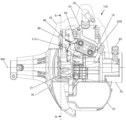
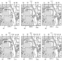
- FIG. 4 is a cross-sectional view taken along the line BB in the maximum output state in the embodiment of the present invention.
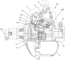
- FIG. 4 is a cross-sectional view of the CC in the maximum output state in the embodiment of the present invention.
- FIG. 12 is an external perspective view of the brush cutter 101 to which the present invention is applied.
- the brush cutter 101 shown in the figure includes a pipe-shaped operating rod 103, a rotary blade 104 provided at one end of the operating rod 103, an engine 102 as a drive source provided at the other end of the operating rod 103, and an operation And a handle 105 provided substantially at the center of the collar 103.
- the operator holding the handle 105 swings the operating rod 103 left and right, and the brush cutting is performed by the rotary blade 104.
- an engine 102 includes a cylinder 13 in which a piston 26 can reciprocate in the vertical direction, and a crankcase 25 provided below the cylinder 13.
- a carburetor 19 and an air cleaner 18 are connected to an intake port, and an exhaust port is connected to the exhaust port.
- the muffler 14 is connected.
- An ignition coil 20 is fixed to the outer periphery of the cylinder 13.
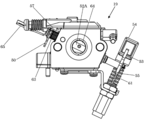
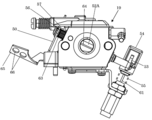
- the carburetor 19 is provided with a throttle shaft 52A.
- the throttle valve 63 changes the opening in the intake passage in conjunction with the throttle shaft 52A, thereby controlling the intake amount of the cylinder 13 and the crankshaft 60 of the engine 102.
- the rotation speed or output is controlled.
- a governor plate 50 having a wind receiving portion 65 is attached to the throttle shaft 52 ⁇ / b> A, and the governor plate 50 is inserted into the cylinder cover 11 through the opening 51. For this reason, the wind receiving portion 65 can rotate about the throttle shaft 52A as a rotation axis, and the throttle shaft 52A also rotates when the wind receiving portion 65 rotates.
- the cooling fan 17 is fixed to the crankshaft 60 of the engine 102 outside the crankcase 25 and is accommodated by the outer surface of the crankcase 25, the fan case 16, and the cylinder cover 11. Cooling is performed by supplying the cooling air CA1 to the cylinder 11 as the cooling fan 17 rotates. At this time, when the wind receiving portion 65 of the governor plate 50 receives the cooling air CA1, the rotational torque is transmitted to the throttle shaft 52A, and the rotational speed or output of the engine 102 can be adjusted by rotating the throttle shaft 52A. .
- a throttle lever 53 that is interlocked with the throttle shaft 52 ⁇ / b> A is disposed, and the throttle lever 53 is accommodated in the opening restriction member 54.
- An opening restriction portion 59 is formed in the opening restriction material 54.
- the opening restriction member 54 is connected to the throttle wire 61.
- the opening restricting member 54 restricts the throttle lever 53 to an idling position (a position where the opening of the throttle valve 63 is minimized) by a return spring 55.
- a torsion spring 63 is attached to the throttle shaft 52A, and always urges the throttle shaft 52A to rotate in a direction that increases the rotational speed or output.
- the governor plate 50 receives the cooling air CA1 to generate torque that rotates the throttle shaft 52A in a direction that reduces the rotational speed or output.
- the throttle lever 53 is urged to the idling position by the return spring 55, so that the throttle shaft 52 ⁇ / b> A is fixed to the idling position at the position regardless of the governor plate 50.
- the throttle shaft 52A is positioned by contacting the throttle stopper 56 and the abutting portion 57 formed on the carburetor 19 as shown in FIG. (Operation by Inclination of Throttle Shaft 52A)
- the throttle shaft 52A and the throttle axis 52B are inclined with respect to the fan rotation shaft 100 (crankshaft 60).
- the cooling fan 17 is inclined at an angle such that the cooling fan 17 side is far from the fan rotation shaft 100 and the anti-cooling fan 17 side is close to the fan rotation shaft 100.
- the direction is inclined toward the cylinder 13.
- the wind receiving portion 65 has a component in the axial direction of the crankshaft 60 in the moving direction, and the opening degree of the throttle valve 63 decreases as the wind receiving portion 65 moves toward the cylinder 13 in the crankshaft 60 direction (to the idling position).
- the throttle valve 63 rotates about the throttle shaft 52A so that the opening degree of the throttle valve 63 increases (closer to the maximum output position) as the distance from the cylinder 13 increases.
- the wind receiving portion 65 is formed so that the projected area of the piston 26 in the reciprocating direction view increases as it moves to the cylinder 13 side.
- the flow velocity of the fan rotation shaft 100 is smaller on the side opposite to the cylinder 13, and the flow velocity is larger on the cylinder 13 side. . Therefore, when there is no load and the throttle shaft 52A is at the idling position (or a position where the rotational speed is low), the cooling air CA1 from the cooling fan 17 toward the cylinder 13 is reliably received along the flow by the wind receiving portion 65. Thus, the rotational torque in the direction of decreasing the rotational speed can be obtained on the throttle shaft 52A, so that the rotational speed can be reliably suppressed. Further, since the flow velocity of the cooling air CA1 is large in the vicinity of the cylinder 13, the torque due to the wind force is further increased, so that the rotation speed can be further suppressed.
- the wind receiving portion 65 rotates in the direction away from the cylinder 13 with respect to the fan rotation shaft 100, the air receiving portion 65 is away from the flow of the cooling air CA1 from the cooling fan 17 toward the cylinder 13, and is difficult to receive the cooling air CA1. Therefore, the rotational torque in the direction of decreasing the rotational speed due to the wind force can be reliably reduced, and the rotational speed or output can be increased by reliably rotating the throttle shaft 52A in the direction of increasing the rotational speed or output. Further, since the flow velocity becomes smaller toward the counter-cylinder 13 side, the torque due to wind force can be further reduced, and the rotation speed or output can be further improved.
- the governor plate 50 can reliably control the engine 102 such that the rotational speed is suppressed when there is no load and the rotational speed or output is increased when the load is applied.
- FIGS. 1 and 2 an air passage from the cooling fan 17 to the cylinder 13 is formed by the cylinder cover 11, the fan case 16, and the ignition coil 20, and the governor plate is formed in the air passage.
- Fifty wind receiving portions 65 are arranged. With this configuration, the cooling air CA1 flows in a concentrated manner toward the air receiving portion 65, so that the air receiving portion 65 reliably receives the cooling air CA1.
- an interval 67A is formed between the wind receiving portion 65 and the ignition coil
- a second interval 67B is formed between the wind receiving portion 65 and the cylinder cover 11.
- the interval 67A is smaller than the second interval 67B.
- the distance 67A becomes wider and the second distance 67B becomes smaller toward the maximum output position
- the distance 67A becomes narrower than the second distance 67B at the maximum output position. Accordingly, the interval 67A becomes narrower as the opening of the throttle valve 63 becomes smaller, so that the wind receiving portion 65 can surely receive the cooling air CA1 from the cooling fan 17 toward the cylinder 13, so that the rotational speed of the engine 102 is increased.
- the interval 67A is widened to secure the air passage area from the cooling fan 17 to the cylinder 13, so that the wind receiving portion 65 is difficult to receive the cooling air CA1 and decreases the rotational speed. While rotating torque can be reduced, the air volume of the cooling air CA1 toward the cylinder 13 is maintained, and the cooling performance of the cylinder can be maintained. Further, when the wind receiving portion 65 is at the maximum output position as shown in FIG. 1, the interval 67A is formed to be wider than the third interval 67C between the wind receiving portion 65 and the cooling fan 17, so the third interval 67C.
- a hole 66 which is a ventilation part of the present invention is formed in the region of the wind receiving part 65 of the governor plate 50.
- the wind receiving portion 65 is far from the cooling fan 17 at the idling position (state 1), is substantially horizontal to the cooling air CA1, and at the maximum output position (state 3). The posture is close to the cooling fan 17 and substantially coincides with the radial direction with respect to the cooling fan 17.
- the wind receiving portion 65 is provided so that the angle with respect to the radial direction of the cooling fan 17 changes by rotating, and the angle with respect to the radial direction increases as the opening of the throttle valve 63 decreases.
- the angle ⁇ formed by the cylinder axis 58 and the wind receiving portion 65 operates so as to become smaller from the idling position to the maximum output position.
- the graph of FIG. 11 conceptually shows the positional relationship between the wind receiving portion 65 and the cooling fan 17, the flow of the cooling air CA ⁇ b> 1, and the torque characteristics due to the wind force at that time.
- the wind receiving portion 65 is substantially horizontal to the cooling air CA1 in a state close to the idling position, and receives the cooling air CA1 from the front, so that the pressure on the surface on the cooling fan 17 side with respect to the cylinder axis 58 is The pressure difference from the anti-cooling fan 17 side increases greatly. This creates a large wind torque.
- the wind receiving portion 65 gradually approaches the maximum output position.
- the wind receiving portion 65 approaches the cooling fan 17 and has a posture along the flow of the cooling air CA1 and the radial direction of the cooling fan 17, and further, the wind receiving portion 65 itself functions as an air guide plate for the cooling air CA1. It becomes like this. Therefore, a flow is formed such that the cooling air CA1 flows along the wind receiving portion 65 at a certain state (state 2), so that there is no pressure difference between the front and back of the wind receiving portion 65, and the wind torque drops sharply. Sometimes. When the wind torque decreases, the torque of the torsion spring 63 increases with respect to the wind torque, and the wind receiving portion 65 operates in a direction that rapidly increases the rotational speed or output.
- the wind receiving portion 65 may be in an unstable vibration state that repeatedly decreases and increases in rotational speed at a certain state (state 2).
- state 1 since the air receiving portion 65 is provided with the air hole 66 as a ventilation portion, the wind torque obtained by the cooling air CA1 at the idling position (state 1) is reduced. From this state, when the rotational speed is reduced by the external load and the air volume of the cooling air CA1 is reduced, the wind receiving portion 65 gradually approaches the maximum output position.
- the air holes 66 do not receive the cooling air CA1
- the air receiving portion 65 can be formed in a wider area, and even if the shape of the air receiving portion 65 varies, the flow hardly changes, and the engine 102 The robustness of the controllability can be improved.
- the opening direction of the air holes 66 is directed to the cylinder 13 or the cylinder axis 58 at the maximum output position, the cooling air CA2 passing through the air holes 66 is smoothly supplied at the maximum output position where the heat generation of the cylinder 13 increases. The cylinder 13 can be supplied and the cooling performance of the cylinder 13 can be maintained.
- the governor plate 50 is provided with a plurality of attachment portions 68 of the torsion spring 63, and the torque by the torsion spring 63 can be attached by switching to a plurality of stages. Therefore, even when applied to the engine 102 having a different displacement or fan diameter, the optimum torque can be easily set again. Therefore, it becomes easy to make the governor plate 50 common to different engines 102, and the cost can be reduced.
- the wind receiving portion 65 is configured to rotate about the throttle shaft 52A.
- the wind receiving portion 65 is configured to rotate about an axis different from the throttle shaft 52A and rotate the throttle shaft 52A via a link or the like. It is also good.
- the ventilation section provided in the area of the wind receiving section 65 allows the cooling air to pass through the area of the wind receiving section 65 in the direction in which the wind receiving section 65 rotates so that the opening degree of the throttle valve 63 is reduced.
- Any shape having a function of reducing the pressure difference between the cooling fan 17 side and the anti-cooling fan 17 side may be used, and instead of the circular hole 66, for example, a square hole or notch may be used.
- regulating portion 60 ... crankshaft, 61 ... throttle wire, 63 ... torsion spring, 64 ... throttle valve, 65 ... Wind receiving portion, 66 ... hole, 67A ... first interval, 67B ... second interval, 67C ... third Septum 68 ... attaching portion, 100 ... fan rotation axis, 101 ... mowing machine, 102 ... engine, 103 ... operating lever, 104 ... cutting blade, 105 ... handle, CA1,2 ... cooling air
Landscapes
- Engineering & Computer Science (AREA)
- Chemical & Material Sciences (AREA)
- Combustion & Propulsion (AREA)
- Mechanical Engineering (AREA)
- General Engineering & Computer Science (AREA)
- Control Of Throttle Valves Provided In The Intake System Or In The Exhaust System (AREA)
- Motor Or Generator Cooling System (AREA)
Abstract
Description
Claims (7)
- ピストンが上下方向に往復動可能なシリンダと、前記シリンダの下方に設けられるクランクケースと、前記ピストンの往復動方向に対して直交して延び、前記ピストンの往復動に伴って回転するクランク軸と、前記シリンダの吸気量を制御し、前記クランク軸の回転数を制御するスロットル弁と、回動することで前記スロットル弁の開度を制御するスロットル軸と、前記クランクケースの外側において前記クランク軸に固定され、前記クランク軸の回転に伴って回転することで前記シリンダを冷却する冷却風を発生させる冷却ファンと、前記冷却風を受け、前記冷却風によって移動することで前記スロットル軸を回動させる風受け部と、を備えるエンジン作業機であって、前記風受け部の移動方向に前記クランク軸の軸方向の成分を持たせ、前記クランク軸方向において前記風受け部が前記シリンダ側に移動するに従い前記スロットル弁の開度が小さくなるようにしたことを特徴とするエンジン作業機。
- 前記風受け部の前記移動は回動であることを特徴とする請求項1に記載のエンジン作業機。
- 前記風受け部の回動軸は、前記クランク軸に対して傾斜しており、その傾斜方向は、前記回動軸の長手方向が前記ファンに向かうに従って前記シリンダ側に位置する方向であることを特徴とする請求項2に記載のエンジン作業機。
- 前記風受け部の回動軸は、前記スロットル軸であることを特徴とする請求項2又は請求項3に記載のエンジン作業機。
- 前記風受け部は、前記シリンダ側に移動するに従い前記ピストンの往復動方向視における投影面積が大きくなることを特徴とする請求項1から請求項4のいずれか1項に記載のエンジン作業機。
- 前記風受け部は、回動することにより前記冷却ファンの放射方向に対する角度が変わり、前記スロットル弁の開度が小さくなるに従って前記放射方向に対する角度が大きくなるよう設けられ、前記風受け部の領域内には、前記スロットル弁の開度が小さくなるように前記風受け部が回動する方向に、前記冷却風を通す通気部が設けられていることを特徴とする請求項2から請求項4のいずれか1項に記載のエンジン作業機。
- ピストンが上下方向に往復動可能なシリンダと、前記シリンダの下方に設けられるクランクケースと、前記ピストンの往復動方向に対して直交して延び、前記ピストンの往復動に伴って回転するクランク軸と、前記シリンダの吸気量を制御し、前記クランク軸の回転数を制御するスロットル弁と、回動することで前記スロットル弁の開度を制御するスロットル軸と、前記クランクケースの外側において前記クランク軸に固定され、前記クランク軸の回転に伴って回転することで前記シリンダを冷却する冷却風を発生させる冷却ファンと、前記シリンダ外周に、前記冷却ファンの外側に位置するよう固定される点火コイルと、前記冷却風を受け、前記冷却風によって移動することで前記スロットル軸を回動させる風受け部と、を備えるエンジン作業機であって、前記風受け部は回動することにより、前記移動を行う構成とし、前記スロットル弁の開度が小さくなるに従い前記風受け部と前記点火コイルとの間隔が狭くなるよう前記風受け部が回動することを特徴とするエンジン作業機。
Priority Applications (3)
| Application Number | Priority Date | Filing Date | Title |
|---|---|---|---|
| CN201680058732.3A CN108138661B (zh) | 2015-10-16 | 2016-09-30 | 发动机式作业机 |
| DE112016004711.8T DE112016004711T5 (de) | 2015-10-16 | 2016-09-30 | Motorgetriebene Arbeitsmaschine |
| JP2017545147A JP6544436B2 (ja) | 2015-10-16 | 2016-09-30 | エンジン作業機 |
Applications Claiming Priority (2)
| Application Number | Priority Date | Filing Date | Title |
|---|---|---|---|
| JP2015-204666 | 2015-10-16 | ||
| JP2015204666 | 2015-10-16 |
Publications (1)
| Publication Number | Publication Date |
|---|---|
| WO2017065024A1 true WO2017065024A1 (ja) | 2017-04-20 |
Family
ID=58517614
Family Applications (1)
| Application Number | Title | Priority Date | Filing Date |
|---|---|---|---|
| PCT/JP2016/079044 Ceased WO2017065024A1 (ja) | 2015-10-16 | 2016-09-30 | エンジン作業機 |
Country Status (4)
| Country | Link |
|---|---|
| JP (1) | JP6544436B2 (ja) |
| CN (1) | CN108138661B (ja) |
| DE (1) | DE112016004711T5 (ja) |
| WO (1) | WO2017065024A1 (ja) |
Cited By (1)
| Publication number | Priority date | Publication date | Assignee | Title |
|---|---|---|---|---|
| CN112881041A (zh) * | 2021-01-11 | 2021-06-01 | 中车青岛四方机车车辆股份有限公司 | 轴箱定位装置及构架试验装置 |
Citations (3)
| Publication number | Priority date | Publication date | Assignee | Title |
|---|---|---|---|---|
| JPS5797131U (ja) * | 1980-12-05 | 1982-06-15 | ||
| JPH06123243A (ja) * | 1992-03-23 | 1994-05-06 | Walbro Far East Inc | 内燃機関の風圧ガバナ装置 |
| JP2005299439A (ja) * | 2004-04-08 | 2005-10-27 | Fuji Heavy Ind Ltd | エンジンの風圧ガバナ機構 |
Family Cites Families (4)
| Publication number | Priority date | Publication date | Assignee | Title |
|---|---|---|---|---|
| FR2318305A1 (fr) * | 1975-07-18 | 1977-02-11 | Gutbrod Sa | Refroidissement et reglage des regimes des moteurs 2 temps |
| US7343898B1 (en) * | 2007-02-13 | 2008-03-18 | Briggs & Stratton Corporation | Air vane governor |
| JP6260140B2 (ja) * | 2013-08-19 | 2018-01-17 | 日立工機株式会社 | エンジン作業機 |
| JP2015124772A (ja) * | 2013-12-27 | 2015-07-06 | 日立工機株式会社 | エンジン作業機 |
-
2016
- 2016-09-30 WO PCT/JP2016/079044 patent/WO2017065024A1/ja not_active Ceased
- 2016-09-30 DE DE112016004711.8T patent/DE112016004711T5/de not_active Withdrawn
- 2016-09-30 JP JP2017545147A patent/JP6544436B2/ja not_active Expired - Fee Related
- 2016-09-30 CN CN201680058732.3A patent/CN108138661B/zh not_active Expired - Fee Related
Patent Citations (3)
| Publication number | Priority date | Publication date | Assignee | Title |
|---|---|---|---|---|
| JPS5797131U (ja) * | 1980-12-05 | 1982-06-15 | ||
| JPH06123243A (ja) * | 1992-03-23 | 1994-05-06 | Walbro Far East Inc | 内燃機関の風圧ガバナ装置 |
| JP2005299439A (ja) * | 2004-04-08 | 2005-10-27 | Fuji Heavy Ind Ltd | エンジンの風圧ガバナ機構 |
Cited By (1)
| Publication number | Priority date | Publication date | Assignee | Title |
|---|---|---|---|---|
| CN112881041A (zh) * | 2021-01-11 | 2021-06-01 | 中车青岛四方机车车辆股份有限公司 | 轴箱定位装置及构架试验装置 |
Also Published As
| Publication number | Publication date |
|---|---|
| JPWO2017065024A1 (ja) | 2018-08-09 |
| CN108138661A (zh) | 2018-06-08 |
| CN108138661B (zh) | 2020-10-30 |
| JP6544436B2 (ja) | 2019-07-17 |
| DE112016004711T5 (de) | 2018-06-28 |
Similar Documents
| Publication | Publication Date | Title |
|---|---|---|
| JP6233018B2 (ja) | エンジン作業機 | |
| JP6313966B2 (ja) | 手で操縦される作業機における内燃エンジンの作動方法 | |
| US9322344B2 (en) | Engine-powered work tool provided with wind governor | |
| JP6110189B2 (ja) | 内燃エンジン | |
| US7520061B2 (en) | Manually guided trimmer | |
| US7363886B2 (en) | Power unit | |
| WO2017065024A1 (ja) | エンジン作業機 | |
| JP6459532B2 (ja) | エンジン作業機 | |
| US10718243B2 (en) | Engine and engine-driven working machine | |
| US10495017B2 (en) | Portable working machine including engine with carburetor and fuel supply control method thereof | |
| US8739418B2 (en) | Engine-driven cutter | |
| EP3237739B1 (en) | Internal combustion engine and method for safe starting the same | |
| JP6398736B2 (ja) | エンジン作業機 | |
| JP2015124772A (ja) | エンジン作業機 | |
| CN103380272A (zh) | 两冲程发动机以及包含其的发动机驱动工作机 | |
| JP6976208B2 (ja) | 汎用エンジン | |
| CN106168170A (zh) | 调速器装置 | |
| WO2016208653A1 (ja) | マフラーカバー及びエンジン | |
| JP5292272B2 (ja) | 風圧式エンジン制御装置 | |
| JP2014047741A (ja) | エンジン及びエンジン作業機 | |
| JP2013147979A (ja) | エンジン及びエンジン作業機 | |
| JP2015224743A (ja) | 動力作業機 | |
| JP6090058B2 (ja) | エンジン作業機 | |
| JP2009115104A (ja) | ダンパ装置 | |
| JP2014108054A (ja) | エンジン駆動ヘッジトリマ |
Legal Events
| Date | Code | Title | Description |
|---|---|---|---|
| 121 | Ep: the epo has been informed by wipo that ep was designated in this application |
Ref document number: 16855278 Country of ref document: EP Kind code of ref document: A1 |
|
| WWE | Wipo information: entry into national phase |
Ref document number: 112016004711 Country of ref document: DE |
|
| ENP | Entry into the national phase |
Ref document number: 2017545147 Country of ref document: JP Kind code of ref document: A |
|
| 122 | Ep: pct application non-entry in european phase |
Ref document number: 16855278 Country of ref document: EP Kind code of ref document: A1 |