WO2017057524A1 - 画像化方法および画像化装置 - Google Patents
画像化方法および画像化装置 Download PDFInfo
- Publication number
- WO2017057524A1 WO2017057524A1 PCT/JP2016/078742 JP2016078742W WO2017057524A1 WO 2017057524 A1 WO2017057524 A1 WO 2017057524A1 JP 2016078742 W JP2016078742 W JP 2016078742W WO 2017057524 A1 WO2017057524 A1 WO 2017057524A1
- Authority
- WO
- WIPO (PCT)
- Prior art keywords
- function
- cone
- wave
- formula
- antenna element
- Prior art date
- Legal status (The legal status is an assumption and is not a legal conclusion. Google has not performed a legal analysis and makes no representation as to the accuracy of the status listed.)
- Ceased
Links
Images





Classifications
-
- G—PHYSICS
- G01—MEASURING; TESTING
- G01N—INVESTIGATING OR ANALYSING MATERIALS BY DETERMINING THEIR CHEMICAL OR PHYSICAL PROPERTIES
- G01N22/00—Investigating or analysing materials by the use of microwaves or radio waves, i.e. electromagnetic waves with a wavelength of one millimetre or more
-
- G—PHYSICS
- G06—COMPUTING OR CALCULATING; COUNTING
- G06T—IMAGE DATA PROCESSING OR GENERATION, IN GENERAL
- G06T12/00—Tomographic reconstruction from projections
-
- A—HUMAN NECESSITIES
- A61—MEDICAL OR VETERINARY SCIENCE; HYGIENE
- A61B—DIAGNOSIS; SURGERY; IDENTIFICATION
- A61B6/00—Apparatus or devices for radiation diagnosis; Apparatus or devices for radiation diagnosis combined with radiation therapy equipment
- A61B6/02—Arrangements for diagnosis sequentially in different planes; Stereoscopic radiation diagnosis
- A61B6/03—Computed tomography [CT]
- A61B6/032—Transmission computed tomography [CT]
-
- A—HUMAN NECESSITIES
- A61—MEDICAL OR VETERINARY SCIENCE; HYGIENE
- A61B—DIAGNOSIS; SURGERY; IDENTIFICATION
- A61B8/00—Diagnosis using ultrasonic, sonic or infrasonic waves
- A61B8/08—Clinical applications
- A61B8/0825—Clinical applications for diagnosis of the breast, e.g. mammography
-
- G—PHYSICS
- G01—MEASURING; TESTING
- G01N—INVESTIGATING OR ANALYSING MATERIALS BY DETERMINING THEIR CHEMICAL OR PHYSICAL PROPERTIES
- G01N22/00—Investigating or analysing materials by the use of microwaves or radio waves, i.e. electromagnetic waves with a wavelength of one millimetre or more
- G01N22/02—Investigating the presence of flaws
-
- G—PHYSICS
- G06—COMPUTING OR CALCULATING; COUNTING
- G06T—IMAGE DATA PROCESSING OR GENERATION, IN GENERAL
- G06T7/00—Image analysis
- G06T7/50—Depth or shape recovery
-
- H—ELECTRICITY
- H04—ELECTRIC COMMUNICATION TECHNIQUE
- H04N—PICTORIAL COMMUNICATION, e.g. TELEVISION
- H04N19/00—Methods or arrangements for coding, decoding, compressing or decompressing digital video signals
- H04N19/10—Methods or arrangements for coding, decoding, compressing or decompressing digital video signals using adaptive coding
- H04N19/169—Methods or arrangements for coding, decoding, compressing or decompressing digital video signals using adaptive coding characterised by the coding unit, i.e. the structural portion or semantic portion of the video signal being the object or the subject of the adaptive coding
- H04N19/17—Methods or arrangements for coding, decoding, compressing or decompressing digital video signals using adaptive coding characterised by the coding unit, i.e. the structural portion or semantic portion of the video signal being the object or the subject of the adaptive coding the unit being an image region, e.g. an object
- H04N19/172—Methods or arrangements for coding, decoding, compressing or decompressing digital video signals using adaptive coding characterised by the coding unit, i.e. the structural portion or semantic portion of the video signal being the object or the subject of the adaptive coding the unit being an image region, e.g. an object the region being a picture, frame or field
Definitions
- the present invention relates to a technique for acquiring and imaging (imaging) internal information of an object using waves, and in particular, an imaging method and an imaging apparatus for acquiring internal information of an object using a wave scattering phenomenon. About.
- X-ray CT X-ray tomography
- MRI Magnetic Resonance Imaging: Nuclear Magnetic Resonance Imaging
- PET PET
- positron Emission Tomography positron tomography
- a wave u such as an electromagnetic wave or an ultrasonic wave is radiated to the object O, and the scattered wave p scattered from the object O in many places around the object O is observed and obtained.
- a technique for visualizing data is employed (see, for example, Patent Document 1 and Non-Patent Document 1).
- Patent Document 1 The technique described in Patent Document 1 is to visualize information inside an object using radio waves.
- the data acquisition is repeated and imaged while correcting the scattered wave data observed by the sensor elements arranged on the circumference with parameters such as conductivity and dielectric constant.
- Non-Patent Document 1 is a technique related to multipath linear array radar, and visualizes information such as defects inside concrete.
- Sensor elements linear multi-array antennas
- arranged in a linear or curved manner on the surface of the object observe the scattered waves of the radiated waves with the sensor, analyze the observation data and visualize it It is.
- Patent Document 1 and Non-Patent Document 1 for example, every time the condition such as the curved surface shape of an object changes, the theory or the internal structure of the device is changed, or the acquired data is re-acquired. Because it is necessary to correct, general-purpose use is difficult. In particular, for an object having a flexible shape such as a living body, the shape of the object and the curvature of the curved surface of the outer shape are often not constant. Therefore, a conventional linear multi-array antenna or an object having a certain shape is used as a model. It is difficult to use the array antenna uniformly. In addition, since it is necessary to reacquire and correct data, there are problems such as a delay in calculation speed and a large use of memory.
- an object of the present invention is to provide an inspection method and an inspection apparatus that are general-purpose and can visualize information inside an object simply and at high speed.
- an imaging method includes: Radiating waves to the object; Receiving the scattered waves scattered by the object at the object; Reconstructing an image relating to internal information of the object from scattered wave data indicating the scattered wave, In the step of reconstructing the image, Deriving a reconstruction function for reconstructing an image related to internal information of the object by solving a partial differential equation using the scattered wave data and an analysis model indicating the shape, Using the reconstruction function, reconstruct an image relating to internal information of the object,
- the partial differential equation is an equation that the reconstruction function satisfies.
- the partial differential equation for the inverse problem is set in the analysis model that observes (inspects) the internal information of the object while freely moving the sensor element having the transmitting antenna element and the receiving antenna element on the object.
- the reconstruction function ⁇ is set for the three-dimensional space, so that the internal information of the object can be visualized in three dimensions with high accuracy and at high speed.
- the object can be observed directly, not through the observation results of other objects.
- this inspection method is an inspection method using scattering tomography by a monostatic method, compared with an inspection device using scattering tomography by a multistatic method, which has a plurality of transmission units and reception units, and has a shape. Can be measured accurately even if it is a flexible inspection object.
- the partial differential equation is Represented using independent variables indicating the position of the transmission point and reception point in the object, A linear partial differential equation in which a scattered field function, which is a function of the field in which the scattered wave is generated, at each point in a space having the same dimension as the number of independent variables,
- an imaging function that is a limit value of a time variable of the reconstruction function may be derived, and an image related to internal information of the object may be reconstructed using the imaging function.
- the shape indicated by the analysis model is a cone
- the imaging function is represented by the following (formula A):
- x is the x coordinate of the position of the transmission point and the reception point
- y is the y coordinate of the position of the transmission point and the reception point
- z is z of the position of the transmission point and the reception point.
- (X, Y, Z) is the origin of the apex of the cone, the direction from the origin toward the center of the bottom of the cone is the Z direction, and the direction parallel to the bottom and passing through the origin is the X direction
- Y is a coordinate parallel to the bottom surface and passing through the origin and perpendicular to the X direction
- ⁇ is a function of dielectric constant
- ⁇ is the reconstruction function
- k x , k y , k z are the wave number x, y, z components
- k is the time wave number
- ⁇ rotates the cone axis. This is the angle of rotation about the axis.
- the shape indicated by the analysis model is a substantially cone having a curved generatrix
- the imaging function is represented by the following (formula C):
- x is the x coordinate of the position of the transmission point and the reception point
- y is the y coordinate of the position of the transmission point and the reception point
- z is z of the position of the transmission point and the reception point.
- (X, Y, Z) is the origin at the apex of the substantially cone, the direction from the origin toward the center of the bottom surface of the approximately cone is the Z direction, and the direction parallel to the bottom surface and passing through the origin is The X direction is the coordinate when the direction parallel to the bottom surface and passing through the origin and perpendicular to the X direction is the Y direction, ⁇ is a function of dielectric constant, ⁇ is the reconstruction function, and a ⁇ is a coefficient, k x , k y , and k z are x, y, and z components of the wave number, k is the wave number of time, and ⁇ is a rotation angle with the substantially conical axis as the rotation axis. .
- the shape indicated by the analysis model is an asymmetric cone
- the imaging function is expressed by the following (formula F) when ⁇ , ⁇ , and ⁇ are variables that satisfy the following (formula E):
- the image relating to the internal information of the object may be reconstructed using a function represented by the following (formula G) obtained by integrating the imaging function with ⁇ . Good. ........:// (Formula E) ........-> (Formula F) ........... (Formula G)
- x is the x coordinate of the position of the transmission point and the reception point
- y is the y coordinate of the position of the transmission point and the reception point
- z is z of the position of the transmission point and the reception point.
- a receiving antenna element that receives the scattered wave and a transmitting antenna element that radiates the wave to the object are provided integrally, and the receiving antenna element and the transmitting antenna element are provided between the receiving antenna element and the transmitting antenna element. Radiating the wave to the object using a probe in which radio wave absorbing means is located, In the receiving step, the scattered wave may be received using the probe.
- the magnitude of the wave directly received by the receiving antenna element can be reduced and received by the receiving antenna element for the magnitude of the directly received wave.
- the ratio of the magnitudes of scattered waves from the target object can be increased. Therefore, a clearer image in the object can be obtained.
- the shape indicated by the analysis model is a cone
- the transmitting antenna element and the receiving antenna element may be integrally moved along a line corresponding to a conical bus in the object.
- the partial differential equation for the inverse problem is set in the analytical model in which the sensor element moves on the conical bus, and the internal information of the object can be imaged at high speed by solving this. .
- the internal information can be imaged more accurately and at high speed with respect to an object having a conical shape.
- the shape indicated by the analysis model is a substantially cone having a curved generatrix
- the transmitting antenna element and the receiving antenna element may be integrally moved along a line corresponding to a substantially conical curved bus in the object.
- the partial differential equation for the inverse problem is set in the analytical model in which the sensor element moves on the curved bus, and by solving this, the internal information of the object can be visualized for general purpose and at high speed. it can.
- internal information can be visualized more accurately and at high speed with respect to an object having a substantially conical shape, for example, a hemispherical shape or a dome shape.
- the shape indicated by the analysis model is an asymmetric cone
- the transmitting antenna element and the receiving antenna element may be integrally moved along a line corresponding to a bus line of an asymmetric cone in the object.
- the partial differential equation for the inverse problem is set in the analytical model in which the sensor element moves on the asymmetric cone-shaped bus, and the internal information of the object can be imaged at high speed by solving this.
- internal information can be visualized more accurately and at high speed with respect to an object having a conical or substantially conical shape lacking a shape or an object having a flexible shape.
- the wave may be a microwave.
- the wave may be a pulse wave or a periodic wave having a predetermined frequency.
- an imaging apparatus includes a transmission antenna element that radiates waves to an object, A receiving antenna element for receiving a scattered wave in which the wave radiated from the transmitting antenna element is scattered in the object; An image reconstruction unit that reconstructs an image related to internal information of the object from scattered wave data indicating scattered waves received by the receiving antenna element; The image reconstruction unit Deriving a reconstruction function for reconstructing an image related to internal information of the object by solving a partial differential equation using the scattered wave data and an analysis model indicating the shape, Reconstructing an image related to the internal information of the object by the reconstruction function, The partial differential equation is an equation that the reconstruction function satisfies.
- this inspection device is an inspection device using a scattering tomography by a monostatic method, compared to an inspection device using a scattering tomography by a multistatic method, which has a plurality of transmission units and reception units, and has a shape. Can be measured accurately even if it is a flexible inspection object.
- the partial differential equation is Represented using independent variables indicating the position of the transmission point and reception point in the object, A linear partial differential equation in which a scattered field function, which is a function of the field in which the scattered wave is generated, at each point in a space having the same dimension as the number of independent variables,
- the image reconstruction unit may derive an imaging function that is a limit value of a time variable of the reconstruction function, and reconstruct an image related to internal information of the object using the imaging function.
- the shape indicated by the analysis model is a cone
- the imaging function is represented by the following (formula A):
- the image reconstruction unit may reconstruct an image related to internal information of the object using a function represented by the following (formula B) obtained by integrating the imaging function with ⁇ . ........:// (Formula A) ........... (Formula B)
- x is the x coordinate of the position of the transmission point and the reception point
- y is the y coordinate of the position of the transmission point and the reception point
- z is z of the position of the transmission point and the reception point.
- (X, Y, Z) is the origin of the apex of the cone, the direction from the origin toward the center of the bottom of the cone is the Z direction, and the direction parallel to the bottom and passing through the origin is the X direction
- Y is a coordinate parallel to the bottom surface and passing through the origin and perpendicular to the X direction
- ⁇ is a function of dielectric constant
- ⁇ is the reconstruction function
- k x , k y , k z are the wave number x, y, z components
- k is the time wave number
- ⁇ rotates the cone axis. This is the angle of rotation about the axis.
- the imaging function is represented by the following (formula C):
- the image reconstruction unit may reconstruct an image related to internal information of the object using a function represented by the following (formula D) obtained by integrating the imaging function with ⁇ . ........:// (Formula C) ........... (Formula D)
- x is the x coordinate of the position of the transmission point and the reception point
- y is the y coordinate of the position of the transmission point and the reception point
- z is z of the position of the transmission point and the reception point.
- (X, Y, Z) is the origin at the apex of the substantially cone, the direction from the origin toward the center of the bottom surface of the approximately cone is the Z direction, and the direction parallel to the bottom surface and passing through the origin is The X direction is the coordinate when the direction parallel to the bottom surface and passing through the origin and perpendicular to the X direction is the Y direction, ⁇ is a function of dielectric constant, ⁇ is the reconstruction function, and a ⁇ is a coefficient, k x , k y , and k z are x, y, and z components of the wave number, k is the wave number of time, and ⁇ is a rotation angle with the substantially conical axis as the rotation axis. .
- the imaging function is expressed by the following (formula F) when ⁇ , ⁇ , and ⁇ are variables that satisfy the following (formula E):
- the image reconstruction unit may reconstruct an image related to internal information of the object using a function represented by the following (formula G) obtained by integrating the imaging function with ⁇ . ........:// (Formula E) ........-> (Formula F) ........... (Formula G)
- x is the x coordinate of the position of the transmission point and the reception point
- y is the y coordinate of the position of the transmission point and the reception point
- z is z of the position of the transmission point and the reception point.
- the imaging apparatus further includes a probe in which the reception antenna element and the transmission antenna element are integrally provided,
- a radio wave absorber may be located between the receiving antenna element and the transmitting antenna element.
- the magnitude of the wave directly received by the receiving antenna element can be reduced and received by the receiving antenna element for the magnitude of the directly received wave.
- the ratio of the magnitudes of scattered waves from the target object can be increased. Therefore, a clearer image in the object can be obtained.
- the shape indicated by the analysis model is a cone
- the transmitting antenna element and the receiving antenna element may be integrally moved along a line corresponding to a conical bus in the object.
- the partial differential equation for the inverse problem is set in the analytical model in which the sensor element moves on the conical bus, and the internal information of the object can be imaged at high speed by solving this. .
- the internal information can be imaged more accurately and at high speed with respect to an object having a conical shape.
- the shape indicated by the analysis model is a substantially cone having a curved generatrix
- the transmitting antenna element and the receiving antenna element may be integrally moved along a line corresponding to a substantially conical curved bus in the object.
- a partial differential equation for the inverse problem is set in an analytical model in which the sensor element moves on a substantially conical bus having a curved bus, and the internal information of the object is generalized and fast by solving this.
- the internal information of the object is generalized and fast by solving this.
- internal information can be visualized more accurately and at high speed with respect to an object having a substantially conical shape, for example, a hemispherical shape or a dome shape.
- the shape indicated by the analysis model is an asymmetric cone
- the transmitting antenna element and the receiving antenna element may be integrally moved along a line corresponding to a bus line of an asymmetric cone in the object.
- the partial differential equation for the inverse problem is set in the analytical model in which the sensor element moves on the asymmetric cone-shaped bus, and the internal information of the object can be imaged at high speed by solving this.
- internal information can be visualized more accurately and at high speed with respect to an object having a conical or substantially conical shape lacking a part or an object having various curved shapes.
- the wave may be a microwave.
- the wave may be a pulse wave or a periodic wave having a predetermined frequency.
- the inverse problem can be analyzed generically and at high speed, and information inside an object having various curved shapes can be easily visualized. It is possible to visualize the internal information of an object having various curved shapes more accurately and at high speed.
- FIG. 1 is a schematic diagram showing a configuration of a mammography apparatus according to a first embodiment. Schematic showing the configuration of the probe in the mammography apparatus according to the first embodiment.
- the figure which shows an example of the usage method of the probe shown in FIG. 1 is a flowchart showing the operation of the mammography apparatus according to the first embodiment.
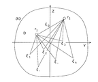
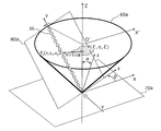
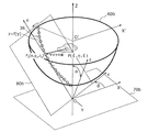
- Analysis model for explaining the principle of the mammography method according to the first embodiment Analysis model for explaining the principle of the mammography method according to the first embodiment
- Analysis model for explaining the principle of the mammography method according to the first embodiment Analysis model for explaining the principle of the mammography method according to the first embodiment
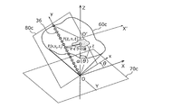
- Analysis model for explaining the principle of the mammography method according to the second embodiment Analysis model for explaining the principle of the mammography method according to the second embodiment
- the inspection method and inspection apparatus according to the present invention are inspection techniques using scattering tomography.
- Scattering tomography is a technology that visualizes and analyzes information inside an object by observing and analyzing the scattered waves when waves are radiated to the object. That is, the inspection method and the inspection apparatus according to the present invention are techniques for detecting a defect or the like of an object nondestructively by analyzing a scattered wave generated by radiating a wave to an object.
- the detailed principle of the scattering tomography is as follows.
- a scattering phenomenon that occurs when a wave is radiated to an object can be expressed using an operator.
- the problem of obtaining the observation data p is called a forward problem.
- An example of using scattering tomography is Multi-Path Linear Array Radar (MPLA Radar).
- MPLA Radar Multi-Path Linear Array Radar
- an antenna element is attached to an object as a sensor element, and even an object having a curvature is approximated as a plane, and an electromagnetic wave radiated from the antenna element and a reflected wave (scattered wave) reflected from the object Therefore, the defect of the object is detected nondestructively.
- An antenna element used for MPLA Radar is composed of a plurality of transmitting antenna elements that radiate waves to an object and a plurality of receiving antenna elements that receive scattered waves generated by the object.
- the position of each antenna element is determined in an analysis model assumed in advance.
- positioned in a certain position is received by the receiving antenna element arrange
- MPLA Radar performs multistatic analysis using scattered waves received by the receiving antenna element and visualizes information inside the object.
- the internal information of the living body can be visualized by assuming a living body model as the analysis model.
- a living body model as the analysis model.
- a breast as an analysis model, it can be used as a mammography for detecting the position and size of cancer tissue inside the breast.
- the shape of the object may not match the assumed analysis model.
- the shape of the object changes depending on the position and orientation of the object. Therefore, the receiving antenna element in the assumed analysis model has a problem that the scattered wave cannot be received normally. . Therefore, it is conceivable that the position of the antenna element and the intensity of the received signal cannot be accurately grasped, and the internal information cannot be grasped accurately when analysis is performed.
- the inspection method and inspection apparatus allows an antenna element composed of a pair of transmission antenna elements and reception antenna elements to freely move on an object in an analysis model of the object assumed in advance.
- the analysis is performed while That is, in the inspection method and the inspection apparatus according to the present invention, a wave is radiated from the transmission antenna element of the paired transmission antenna element and reception antenna element to the object, and the scattered wave is transmitted to the transmission antenna that radiates the wave.
- the signal is received by a pair of receiving antenna elements.
- a monostatic analysis is performed using the scattered wave received with the receiving antenna element, and the information inside an object is imaged.
- a cone having a linear bus is used as a model.
- a mammography apparatus will be described as an inspection apparatus, a breast as an object having a substantially conical shape, and a cancer tissue in the breast as a defective tissue.
- the transmitting antenna element and the receiving antenna element constituting the probe which is a sensor element are moved along the generatrix. That is, the transmitting antenna element and the receiving antenna element are moved together along a line corresponding to a conical bus line in the object.
- the line corresponding to the conical generatrix is a line corresponding to the conical generatrix when the shape of the object 10 is regarded as a cone.
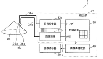
- FIG. 1 is a schematic diagram showing a configuration of a mammography apparatus according to the present embodiment.
- FIG. 2 is a schematic diagram showing the configuration of the probe in the mammography apparatus according to the present embodiment.
- FIG. 3 is a diagram illustrating an example of a method of using the probe illustrated in FIG.
- the mammography apparatus 1 includes a probe 36 and a detection unit 20.
- the probe 36 is a sensor element that detects internal information of the object 10, and includes a pair of transmission antenna elements 36a and reception antenna elements 36b as shown in FIG.
- Each of the transmission antenna element 36a and the reception antenna element 36b may be an antenna array including a plurality of transmission points and reception points.
- the probe 36 has a configuration in which a transmission antenna element 36 a and a reception antenna element 36 b are joined via a wave absorbing means (radio wave absorbing means) 38.
- the transmitting antenna element 36a and the receiving antenna element 36b are connected to coaxial cables 34a and 34b, respectively.
- the wave absorbing means is means for absorbing the wave received by the transmitting antenna element 36a, and is a radio wave absorbing means when the wave is a radio wave such as a microwave.
- the wave absorbing means is a radio wave absorbing means will be described, but the present invention is not limited to this example.
- the relative position between the transmitting antenna element 36a and the receiving antenna element 36b is fixed.
- the configuration of the probe 36 is not limited to this configuration. It is preferable that the transmission antenna element 36a and the reception antenna element 36b are integrally provided via the radio wave absorbing means 38. That is, it is preferable that the receiving antenna element 36b and the transmitting antenna element 36a are integrally provided in the probe 36, and the radio wave absorbing means 38 is located between the receiving antenna element 36b and the transmitting antenna element 36a.
- “Provided integrally” means a state in which the transmitting antenna element 36a and the receiving antenna element 36b are provided in the probe 36, and the transmitting antenna element 36a and the receiving antenna element 36b can move together.
- the transmission antenna element 36a and the reception antenna element 36b are provided integrally, the transmission antenna element 36a and the reception antenna element 36b are arranged in close contact via the radio wave absorbing means 38.
- a case where there is a gap between the antenna element and the radio wave absorber 38 is included.
- the case where there is a gap between the antenna element and the radio wave absorber 38 means that there is a gap between at least one of the transmission antenna element 36a and the radio wave absorber 38 and between the reception antenna element 36b and the radio wave absorber 38.
- a radio wave absorber can be used between the transmitting antenna element 36a and the receiving antenna element 36b.
- “Through the electromagnetic wave absorbing means 38” means that the surface of the transmitting antenna element 36a facing the receiving antenna element 36b or the surface of the receiving antenna element 36b facing the transmitting antenna element 36a has a radio wave absorbing material (wave This includes cases where a film is formed by means such as coating, or a case where a plate-like component made of a radio wave absorbing material is adhered and fixed on the surface.
- the radio wave absorber 38 only needs to be able to reduce the size of the microwave (wave) directly received by the receiving antenna element 36b among the microwaves (wave) transmitted from the transmitting antenna element 36a.
- the radio wave absorbing material is a conductive material, specifically, metal, carbon or the like.
- the code generated by the code generator 32a is propagated to the transmitting antenna element 36a via the coaxial cable 34a.
- the signal received by the antenna element 36b is propagated to the receiving circuit 32b via the coaxial cable 34b. Thereby, the receiving circuit 32b detects the received signal.
- the probe 36 measures the internal information of the object 10 while moving on the object 10 in accordance with a user instruction (operation).
- the probe 36 is configured to be freely movable with respect to the object 10.
- the transmitting antenna element 36 a transmits a wave toward the object 10, and the receiving antenna element 36 b receives a scattered wave scattered by the scatterer 10 a inside the object 10.
- a microwave is described as an example of the wave, but the present invention is not limited to the microwave, and may be an electromagnetic wave or an ultrasonic wave in another band.
- the detection unit 20 includes a control device 30, an image reconstruction unit 40, a code generator 32a, and a reception circuit 32b.
- the control device 30 controls the transmission of the wave from the code generator 32a to the object 10, the reception of the scattered wave by the receiving circuit 32b, and the analysis of the scattered wave received by the image reconstruction unit 40.
- the control device 30 propagates the trigger signal to the code generator 32a.
- the mammography device 1 transmits a wave from the transmitting antenna element 36 a to the target, receives the scattered wave from the scatterer 10 a by the receiving antenna element 36 b, and further receives the scattered wave by the image reconstruction 40. To generate an image.
- the code generator 32a generates a wave radiated from the transmission antenna element 34a as a code based on the trigger signal from the control device 30, and conveys it to the transmission antenna element 34a.
- the code generator 32a generates, for example, the transmission timing and number of waves radiated from the transmission antenna element 36a, and the transmission gain as codes.
- the wave radiated from the transmitting antenna element 36a to the object 10 is, for example, a microwave.
- the receiving circuit 32b conveys microwave scattered wave data received by the receiving antenna element 36b to the image reconstruction unit 40. At this time, the received scattered wave data may be amplified by the receiving circuit 32 b or may be subjected to signal processing such as AD conversion in the control device 30.
- the image reconstruction unit 40 analyzes the scattered wave data conveyed from the receiving circuit 32b, and visualizes the scattered wave data using an image reconstruction algorithm described later. Thereby, an image corresponding to the internal information of the object 10 is reproduced on the image display 50.
- the image display device 50 is a monitor screen and outputs data calculated by the image reconstruction unit 40 as a video.
- an analysis model having a conical shape or a substantially conical shape may be assumed as the analysis model used in the image reconstruction algorithm.
- a conical analysis model in which the diameter of a circle on the bottom surface is 30 cm is assumed.
- the probe 36 may be moved in a line along a generatrix line from the apex of the cone toward the bottom surface. That is, the transmitting antenna element 36a and the receiving antenna element 36b may be moved so as to form a line in the same direction as the axis of the conical rotation object when viewed in plan from at least one direction.
- the rotation target axis of the cone indicates a straight line connecting the apex of the cone and the center of the bottom surface of the cone.
- the transmitting antenna element 36a and the receiving antenna element 36b move in pairs.
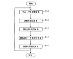
- FIG. 4 is a flowchart showing the operation of the mammography apparatus 1 according to the present embodiment shown in FIG.
- a method for imaging (imaging) internal information of the breast, which is the object 10, by the mammography apparatus 1 is as follows.
- the probe 36 is placed on the object 10 (S10). And a wave is radiated
- a wave for example, a microwave is used.
- the code generator 32a adjusts the wavelength, amplitude, and the like of the microwave, and radiates the object 10 from the transmitting antenna element 36a.
- the scattered wave (scattered wave) reflected by the normal tissue and cancer tissue inside the object 10 is received by the receiving antenna element 36b (S12).
- the normal tissue and cancer tissue correspond to the scatterer 10a shown in FIG.
- the wave is an electromagnetic wave such as a microwave
- the normal tissue and the cancer tissue have different dielectric constants, and thus the intensity of the scattered wave is different.
- the received scattered wave may be amplified or converted to a format suitable for analysis in the image reconstruction unit 40 such as AD conversion in the receiving circuit 32b.
- scattered wave data indicating the received scattered wave is conveyed from the receiving circuit 32b to the image reconstruction unit 40.
- the transported scattered wave data is analyzed (S13).
- the scattered wave data is analyzed by an image reconstruction algorithm described below.
- an imaging function imaging function
- video (image) corresponding to the normal tissue and cancer tissue inside the target object 10 is reconfigure
- the probe 36 is moved, the probe 36 is arrange
- data obtained by reconstruction using an imaging function (imaging function) need not be a moving image, but may be an image, that is, a still image.
- the reconstructed video data is conveyed from the image reconstruction unit 40 to the monitor 50 and displayed on the monitor 50. Thereby, the presence of the cancer tissue inside the object 10 and its position, shape and size can be confirmed.
- the image reconstruction unit 40 reconstructs an image related to the internal information of the object 10 from the scattered wave data indicating the scattered wave received by the reception antenna element 36b. Specifically, the image reconstruction unit 40 derives a reconstruction function by solving the partial differential equation using the scattered wave data and the analysis model indicating the shape. And the image regarding the internal information of the target object 10 is reconstructed by the reconstruction function.
- the partial differential equation is an equation that is satisfied by a reconstruction function for reconstructing an image related to internal information of an object.
- the partial differential equation is an expression expressed using independent variables indicating the positions of the transmission point and the reception point in the object.
- the partial differential equation is a linear partial differential equation in which a scattered field function, which is a function of a field in which a scattered wave is generated, at each point in a space having the same dimension as the number of independent variables.
- the image reconstruction unit derives an imaging function that is the limit value of the time variable of the reconstruction function, and reconstructs an image related to the internal information of the object using the imaging function.
- This image reconstruction algorithm is the image reconstruction principle of the mammography apparatus 1 according to the present embodiment, in which a cone having a linear bus is used as an analysis model.
- ⁇ Image reconstruction algorithm> 5 to 7 are analysis models for explaining the principle of the scattering tomography method according to the present embodiment.
- the object to be visualized is a cone having a straight generatrix.
- a wave radiation point (transmitting antenna element 36a) and a receiving point (receiving antenna element 36b) are arbitrarily installed on the bus. That is, the analysis model is such that the probe 36 moves on the generatrix.
- This image reconstruction algorithm performs monostatic analysis assuming that the radiation point and the reception point are at the same position. Then, using the transmission data indicating the radiated wave radiated from the radiation point and the scattered wave data indicating the scattered wave received at the reception point, information inside the imaging target is visualized.
- a simple mathematical explanation of the image reconstruction algorithm is to first set the solution (function) necessary for visualization, construct an equation from the solution, and obtain a more exact solution from the transmitted data and received data. It solves the inverse problem.
- a green function (reconstruction function) necessary for visualization is set.
- a partial differential equation relating to a three-dimensional space composed of four variables (t, x, y, z) in which this function becomes a solution (function) is constructed.
- the partial differential equation is solved using the transmission data radiated from the transmission antenna element 36a and the reception data (scattered data) received by the reception antenna element 36b as boundary conditions. Thereby, an imaging function is obtained, and information inside the object can be visualized with high quality and high speed.
- the coordinates of the wave transmission point r 1 and the reception point r 2 are always equal.
- the value at the boundary ⁇ D of G (r, ⁇ ) is a measurement value (transmission data and reception data) in the probe 36.
- the above equation is solved under this boundary condition, and a function ⁇ (r) related to the gradient of the dielectric constant in the region D to be obtained from the result is defined.
- L the differential operator L ( ⁇ / ⁇ t, ⁇ / ⁇ r 1 , ⁇ / ⁇ r 2 ) appearing here.
- the object to be visualized is a cone 60a having a linear bus as shown in FIG.
- the probe 36 moves in a line along the generatrix of the cone 60a.
- the probe 36 may also be rotated about an axis passing through the apex of the cone 60a and the center of the bottom surface of the cone 60a. That is, the transmitting antenna element 36a and the receiving antenna element 36b perform measurement while moving in a line in the same direction as the axis of the cone 60a to be analyzed as a model when viewed in plan from at least one direction.
- the rotation target axis of the cone indicates a straight line connecting the apex of the cone and the center of the bottom surface of the cone.
- the virtual tangent plane 80a of the cone 60a at the position of the probe 36 is assumed, the virtual tangent plane 80a is rotated, and scattered wave data is obtained for all rotation angles ⁇ .
- the three-dimensional structure inside the cone 60a is reconstructed from such monolithic time series data on the surface of the cone 60a. The theory will be explained below.
- the vertex of the cone 60a is the point O
- the center of the bottom circle of the cone 60a is the point O ′.
- a direction from the point O toward the point O ′ is defined as a Z direction (Z-axis direction).
- a plane passing through the point O and parallel to the bottom surface of the cone 60a is defined as a reference plane 70a.
- An arbitrary direction on the reference plane 70a is defined as an X direction (X axis direction), and a direction perpendicular to the X direction on the reference plane 70a is defined as a Y direction (Y axis direction).
- a direction parallel to the X direction is defined as an X ′ direction (X ′ axis direction), and a direction parallel to the Y direction is defined as a Y ′ direction (Y ′ axis direction).
- a plane in contact with the cone 60a at the position of the probe 36 is defined as a tangential plane 80a.
- One direction of the intersection line where the tangential plane 80a and the reference plane 70a intersect is defined as an x direction (x axis direction).
- the direction from the point O toward the bottom surface of the cone 60a is defined as the y direction (y-axis direction).
- a direction perpendicular to the x direction and the y direction is defined as a z direction (z axis direction).
- the x-axis is rotated about the Z-axis, and the angle between the X-axis and the x-axis is ⁇ . Further, the angle between the Z axis and the z axis is ⁇ .
- FIG. 7 is a schematic diagram in which the locus of the probe 36 moving on the generatrix of the cone 60a shown in FIG. 6 is partially enlarged.
- the receiving antenna 36b at the point P 2 (x, y 2 , z) P 1 (x, y, z).
- the measurement points P 1 and P 2 move on an arbitrary straight line on which the linear array antenna 36 is arranged.
- Equation 7 is organized as (Equation 8).
- Equation 8 This (Equation 8) was derived assuming a steady state, but it is easy to extend to a non-stationary case. In order to extend (Equation 8) to the non-stationary case, the following (Equation 9) is substituted for variables in (Equation 8).
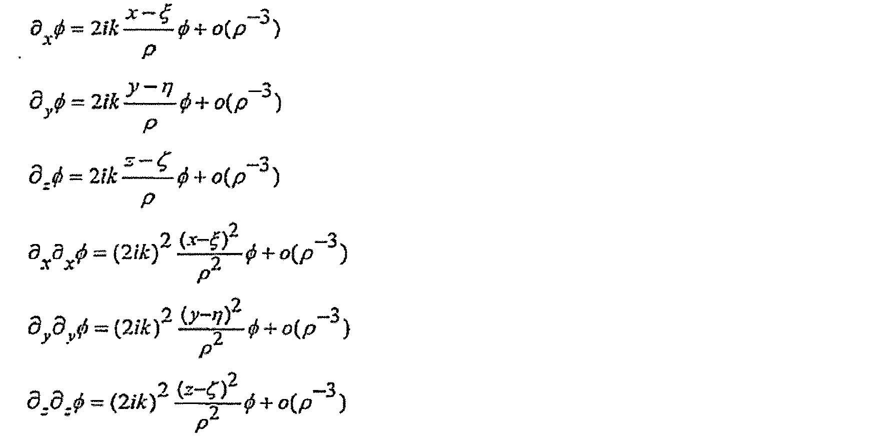
- Equation 10 corresponds to the partial differential equation in the present invention.
- Equation 10 By applying differentiation to the integral kernel in (Equation 10), ⁇ also satisfies the partial differential equation.
- This equation is a three-dimensional pseudo wave equation including four variables t, x, y, and z.
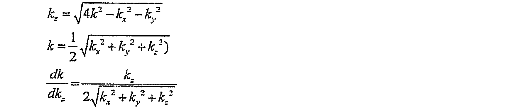
- variable conversion shown in the following (formula 27) is performed in the spectrum region.
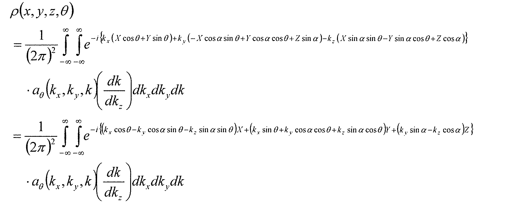
- k x , k y , k z and the like are functions of ⁇ , ⁇ , and ⁇ as in (Equation 26) and (Equation 28), and therefore, using only the Fourier transform, Data can be converted to global coordinates.
- This image function can reconstruct an image related to internal information of an object.
- the mammography apparatus 1 is particularly effective for observing defective tissues in the breast.
- the observation by the mammography apparatus 1 according to the present embodiment uses 1 to 10 GHz UWB (ultra wide band) microwaves.
- Microwaves are effective for observing defective tissues in the breast because attenuation of microwaves is extremely small for living bodies, particularly lipids.
- the apparatus configuration is simpler than that of MRI, and no other substance such as a contrast agent is required, so that it can be used for general purposes.
- the mammography apparatus 1 according to the present embodiment uses the above-described inverse scattering theory, and based on the multipath (multistatic) scattered wave data of the microwave, the three-dimensional components inside the living body such as the breast. Since it is visualized, internal information (configuration) of the living body can be visualized for general purpose and at high speed.
- FIG. 8 is a schematic diagram illustrating an experimental model for a measurement experiment using the mammography apparatus 1 according to the first embodiment.
- FIG. 9 is a diagram illustrating a measurement result obtained by measuring the experimental model illustrated in FIG. 8 with a mammography apparatus.
- the experimental model 100 assumes a pig's breast.
- a plastic container 100a having an inner diameter of 30 cm and a height of about 10 cm has a diameter of 1 mm and a relative dielectric constant.
- five water-filled rubber hoses 100c having a cross-sectional diameter of 5 mm are arranged so as to be filled with six alumina balls 100b and embedded in the alumina balls 100b.
- a microwave of 10 GHz or less was used as the microwave transmitted from the transmission antenna.
- the transmitting antenna 36a and the receiving antenna 36b used have a size of a portion of about 15 mm ⁇ 15 mm in contact with the experimental model 100.
- the five water-filled rubber hoses 100c arranged in the experimental model 100 were observed as shown in FIG. I was able to.
- the water-filled rubber hose 100c was observed when the depth from the surface was about 54 mm. This observation is valid for the model of FIG.
- the mammography apparatus 1 is particularly effective for observing defective tissues in the breast.
- the partial differential equation for the inverse problem is set and solved in the analysis model that moves the probe 36 along the generatrix of the cone 60a. Get visualization function.
- the internal information of the target object 10 can be imaged for general purpose and at high speed.
- the mammography apparatus 1 uses microwaves as waves, the possibility of being exposed to radiation when radiated on a living body as compared with an observation method using X-rays. There is no safety. Moreover, since the contrast ratio between the cancer tissue and the normal tissue is large when imaged as compared with the observation method using X-rays, the observation can be performed with high sensitivity and in a short time. In addition, since the probe can be in contact with the inspection target portion for observation, the apparatus can be reduced in size and cost.
- the observation can be performed by contacting the probe with the inspection target portion without squeezing the inspection target portion, it is possible to easily perform the observation while wearing the patient without suffering.
- microwaves are used as the waves.
- the present invention is not limited to microwaves, and may be electromagnetic waves in other frequency bands or ultrasonic waves.
- a microwave since a microwave is used, a periodic wave having a predetermined frequency is used.
- the wave is not limited to a periodic wave, and a pulse wave may be used.
- the breast is described as an example of the object, but the object is not limited to the breast, and may be another living body or an object, for example, a conical concrete support.
- the configuration of the mammography apparatus 1 according to the present embodiment is substantially the same as that of the mammography apparatus 1 according to the first embodiment, but the cone bus in the cone analysis model shown in the first embodiment is curved. There is a difference from the mammography apparatus 1 shown in the first embodiment in that the transmitting antenna element 36a and the receiving antenna element 36b move along the curved bus. Therefore, the image reconstruction algorithm performed by the image reconstruction unit of the mammography apparatus 1 according to the present embodiment is also different from that of the mammography apparatus 1 according to the first embodiment.
- the transmission antenna element 36a and the reception antenna element 36b are integrally moved along a line corresponding to a substantially conical curved bus line in the object 10.
- the substantially cone is a cone having a curved generatrix
- the line corresponding to the substantially cone generatrix is an abbreviation when the shape of the object 10 is regarded as an approximately cone having a curve generatrix. This is a line corresponding to a conical curved bus.
- ⁇ Image reconstruction algorithm> 10 and 11 are analysis models for explaining the principle of the scattering tomography method according to the present embodiment.
- derivation of the visualization function of the mammography apparatus according to the present embodiment will be described using the models shown in FIGS. 10 and 11 as analysis models.
- the object to be imaged (object 10) is a cone having a curved generatrix, that is, a hemispherical or dome-shaped cone.
- a wave radiation point one transmission antenna element 36a
- a reception point one reception antenna element 36b
- the analysis model is such that the probe 36 moves on the generatrix of a cone having a curved generatrix.
- This image reconstruction algorithm performs monostatic analysis assuming that the radiation point and the reception point are at the same position. Then, using the transmission data indicating the radiated wave radiated from the radiation point and the scattered wave data indicating the scattered wave received at the reception point, information inside the imaging target is visualized.
- the object to be visualized is a cone (substantially cone) 60b having a curved generatrix as shown in FIG.
- the probe 36 moves along the generatrix of the cone 60b.
- the probe 36 may rotate about an axis passing through the apex of the cone 60b and the center of the bottom surface of the cone 60b. That is, the probe 36 composed of a plurality of transmitting antenna elements 36a and a plurality of receiving antenna elements 36b is lined in the same direction as the axis of rotation of the cone 60b as an analysis model when viewed in plan from at least one direction. Measure while moving in the shape.
- the rotation target axis of the cone indicates a straight line connecting the apex of the cone and the center of the bottom surface of the cone.
- the virtual tangent plane 80b rotates about an axis passing through the apex of the cone 60b and the center of the bottom surface of the cone 60b.
- scattered wave data is obtained for all rotation angles ⁇ . From the monostatic time series data on the surface of the cone 60b, the three-dimensional structure inside the cone 60b is reconstructed. The theory will be explained below.
- the vertex of the cone 60b is a point O
- the center of the bottom circle of the cone 60b is a point O ′.
- a direction from the point O toward the point O ′ is defined as a Z direction (Z-axis direction).
- a plane in contact with the cone 60b at the position of the probe 36 is defined as a tangential plane 80b.
- a plane that includes a point where the tangent plane 80b intersects the Z axis and is parallel to the bottom surface of the cone 60b is defined as a reference plane 70b.
- An arbitrary direction on the reference plane 70b is defined as an X direction (X axis direction), and a direction perpendicular to the X direction on the reference plane 70b is defined as a Y direction (Y axis direction).
- a direction parallel to the X direction is defined as an X ′ direction (X ′ axis direction), and a direction parallel to the Y direction is defined as a Y ′ direction (Y ′ axis direction).
- One direction of the intersection line where the tangential plane 80b and the reference plane 70b intersect is defined as an x direction (x axis direction).
- x direction a direction from the point O toward the bottom surface of the cone 60b
- y direction a direction from the point O toward the bottom surface of the cone 60b
- z direction a direction perpendicular to the x direction and the y direction.
- the x axis is rotated about the Z axis, and the angle between the X axis and the x axis is ⁇ . Further, the angle between the Z axis and the z axis is ⁇ .
- FIG. 11 is a schematic diagram in which the locus of the probe 36 moving on the generatrix of the cone 60b shown in FIG. 10 is partially enlarged. As shown in FIG. 11, the x and y coordinates are set on the surface of the object, and the z coordinate is set in the normal direction of the surface of the object. In this analysis model, the probe 36 moves in a curved surface shape in the xyz space.
- a green function (reconstruction function) necessary for visualization is set first, as in the mammography apparatus 1 according to the first embodiment. Then, a partial differential equation relating to a three-dimensional space composed of four variables (t, x, y, z) in which this function becomes a solution (function) is constructed. Then, a strict imaging function of the partial differential equation is obtained using the transmission data radiated from the transmission antenna element 36a and the reception data (scattered data) received by the reception antenna element 36b as boundary conditions. Thereby, the information inside the object can be visualized with high quality and high speed.
- G (r 1 , r 2 , ⁇ ) is the sum of reflected signals from all points ⁇ , and since there are many reflection points in the region, G (r 1 , r 2 , ⁇ ) It can be considered in the same manner as (Formula 1) shown in Embodiment 1.
- the constraints imposed transmission point of the wave r 1 and the reception point r 2 is intended moves on a curved surface which is r 1 and r 2, and, r 1 and r 2 Are substantially the same positions (coordinates).
- the cone bus in the analysis model of the first embodiment is curved, and along the curved bus, the transmission antenna And the receiving antenna moves.
- the antenna array may also rotate around the Z axis.
- a function ⁇ such as the following (Expression 31) is introduced. Note that ⁇ shown in (Expression 34) corresponds to a reconstruction function (solution) for reconstructing an image related to internal information of an object in the present invention.
- the time factor is proportional to exp- i ⁇ t , and the wave number is k.
- the kernel function in the integrand term of the above equation is set as ⁇ .
- z I and z J satisfy the following expressions.
- a (k x , k y , k) is obtained as in the following (Formula 53).
- Equation 59 the equation for converting (x, y ′) to (X, Y) is as follows (Equation 59).
- variable transformation inverse transformation
- Expression 62 variable transformation
- the reconstruction function at the angle ⁇ is as follows (Formula 64).
- This image function reconstructs an image related to the internal information of the object 10. Therefore, an image related to the internal information of the target object 10 such as a defect inside the target object 10 can be visualized for general purpose and at high speed. Further, in the step of reconstructing the image, the setting of the function ⁇ is performed for a three-dimensional space, so that the internal information of the object 10 having a curved surface with a large curvature can be visualized more accurately and at high speed. .
- the mammography apparatus sets the partial differential equation for the inverse problem in the analysis model that moves the probe 36 in a curved surface shape, and obtains the imaging function by solving this.
- the mammography apparatus which analyzes the scattered wave of the wave radiated
- the mammography apparatus according to the present embodiment is different from the mammography apparatus 1 according to the first embodiment in that an object having an asymmetric conical shape is used as an analysis model.
- the transmission antenna element 36a and the reception antenna element 36b are integrally moved along a line corresponding to the asymmetric cone bus of the object 10.
- the line corresponding to the bus of the asymmetric cone is a line corresponding to the bus of the cone when the shape of the object 10 is regarded as an asymmetric cone.
- the shape of the living body is completely the same as the analytical model shown in the first and second embodiments, although a part of the shape is a cone or a substantially conical shape having a rotationally symmetric shape. May not apply.
- an analysis model in the mammography apparatus 1 according to the present embodiment may be used.
- FIG. 12 is an analysis model for explaining the principle of the scattering tomography method according to the present embodiment.
- the image reconstruction algorithm of the mammography apparatus according to the present embodiment is almost the same as the image reconstruction algorithm of the mammography apparatus according to the first embodiment, but the angle ⁇ in the analysis model shown in FIG. Is different from the mammography apparatus 1 according to the first embodiment.
- the object 10 has a shape of a rotationally asymmetric cone, and a part of the object 10 is missing.
- the reconstruction function at the angle ⁇ is as follows (Formula 68).
- the mammography apparatus According to the mammography apparatus according to the present embodiment, even if the shape of a living body to be observed does not completely correspond to the shape of a cone having a rotationally symmetric shape or a substantially cone shape, An imaging function can be obtained by setting and solving the partial differential equation. As a result, in the mammography device that analyzes the scattered waves of the waves radiated to the object, even if the object is flexible or not a perfect cone or a substantially cone, the internal information of the object is Moreover, it can be visualized at high speed.
- the analysis model lacking a part of the cone analysis model shown in Embodiment 1 has been described as an example, but one of the cone analysis models shown in Embodiment 2 is used.
- An analysis model with missing parts may be used.
- the variable conversion formula and the inverse conversion formula for changing the variable in the spectrum domain are changed for (expression).
- an imaging function can be obtained.
- mammography is described as an example, and thus a living body as a target object, specifically, a breast is described as an example.
- the target is not limited to a breast, but other living bodies. It may be a structure.
- a living body not only a living body but object structures other than a living body may be sufficient.
- a structure such as a conical concrete support may be used.
- an analysis model suitable for the shape of the object may be constructed as appropriate.
- microwaves are used as the waves.
- the present invention is not limited to microwaves, and may be electromagnetic waves or ultrasonic waves in other frequency bands.
- a microwave since a microwave is used, a periodic wave having a predetermined frequency is used.
- the wave is not limited to a periodic wave, and a pulse wave may be used.
- the above arithmetic expression and the derivation procedure of the arithmetic expression are examples, and another arithmetic expression and another derivation procedure may be used.
- another processing unit may execute a process executed by a specific processing unit. Further, the order in which the processes are executed in the inspection apparatus may be changed, and a plurality of processes may be executed in parallel.
- the observation step of the internal information of the object in the inspection apparatus of the present invention may be executed by a computer.
- the present invention can be realized as a program for causing a computer to execute the steps included in the scattering tomography method.
- the present invention can be realized as a non-transitory computer-readable recording medium such as a CD-ROM in which the program is recorded.
- the plurality of components included in the inspection apparatus may be realized as an LSI that is an integrated circuit. These components may be individually made into one chip, or may be made into one chip so as to include a part or all of them. Although referred to here as an LSI, it may be referred to as an IC (Integrated Circuit), a system LSI, a super LSI, or an ultra LSI depending on the degree of integration.
- LSI Integrated Circuit
- the method of circuit integration is not limited to LSI, and implementation with a dedicated circuit or a general-purpose processor is also possible.
- An FPGA Field Programmable Gate Array
- a reconfigurable processor that can reconfigure the connection and setting of circuit cells inside the LSI may be used.
- An inspection method for inspecting an internal state of the object by analyzing scattered waves of waves radiated to the object, Radiating the wave to the object by a transmitting antenna element that abuts the object and radiates the wave to the object; The scattered wave is received by a receiving antenna element that is provided integrally with the transmitting antenna element and receives the scattered wave scattered by the wave transmitted from the transmitting antenna element in contact with the object.
- a reconstruction function for reconstructing an image related to the internal information of the object is set in advance for a three-dimensional space having the same shape as the object, Construct a partial differential equation that the asymptotic formula of the reconstruction function satisfies, Deriving an imaging function obtained by solving the partial differential equation from the scattered wave data, An inspection method for reconstructing an image relating to internal information of the object by the imaging function.
- the object has a conical shape; 1. The transmitting antenna element and the receiving antenna element are moved together along the conical bus of the object 1-1. Inspection method described in 1. 1-3.
- the object has a substantially conical shape having a curved generatrix, 1.
- the transmitting antenna element and the receiving antenna element are moved together along the curved busbar 1-1.
- Inspection method described in 1. 1-4. The object has an asymmetric cone shape; 1.
- the transmitting antenna element and the receiving antenna element move together along the asymmetric cone-shaped busbar 1-1.
- the wave is a microwave 1-1. To 1-4.
- the inspection method as described in any one of these. 1-6.
- the wave is a pulse wave or a periodic wave having a predetermined frequency 1-1. To 1-4.
- An inspection device for inspecting an internal state of the object by analyzing scattered waves of waves radiated to the object, A transmitting antenna element that contacts the object and radiates the wave to the object; A receiving antenna element that is provided integrally with the transmitting antenna element and receives scattered waves in which the wave radiated from the transmitting antenna element in contact with the object is scattered on the object; An image reconstruction unit that reconstructs an image related to internal information of the object from scattered wave data indicating scattered waves received by the receiving antenna element; The image reconstruction unit A reconstruction function for reconstructing an image related to the internal information of the object is set in advance for a three-dimensional space having the same shape as the object, Construct a partial differential equation that the asymptotic formula of the reconstruction function satisfies, Deriving an imaging function obtained by solving the partial differential equation from the scattered wave data, An inspection apparatus that reconstructs an image related to internal information of the object by the imaging function.
- the object has a conical shape; 2. The transmitting antenna element and the receiving antenna element are moved together along the conical generatrix of the object 2-1.
- the object has a substantially conical shape having a curved generatrix, The transmitting antenna element and the receiving antenna element are moved together along the curved busbar 2-1.
- the object has an asymmetric cone shape; 2. The transmitting antenna element and the receiving antenna element move together along the asymmetric cone-shaped busbar 2-1.
- the wave is a microwave 2-1. To 2-4.
- the wave is a pulse wave or a periodic wave having a predetermined frequency 2-1.
- To 2-4. The inspection device according to any one of the above.
- the inspection apparatus and the inspection method according to the present invention are useful for inspection of an object having a flexible shape, and can be applied to medical equipment such as a mammography apparatus, for example.
Landscapes
- Health & Medical Sciences (AREA)
- Engineering & Computer Science (AREA)
- Life Sciences & Earth Sciences (AREA)
- Physics & Mathematics (AREA)
- General Physics & Mathematics (AREA)
- General Health & Medical Sciences (AREA)
- Pathology (AREA)
- Medical Informatics (AREA)
- Theoretical Computer Science (AREA)
- Veterinary Medicine (AREA)
- Biomedical Technology (AREA)
- Heart & Thoracic Surgery (AREA)
- Radiology & Medical Imaging (AREA)
- Molecular Biology (AREA)
- Surgery (AREA)
- Animal Behavior & Ethology (AREA)
- Nuclear Medicine, Radiotherapy & Molecular Imaging (AREA)
- Public Health (AREA)
- Biophysics (AREA)
- Biochemistry (AREA)
- Chemical & Material Sciences (AREA)
- Analytical Chemistry (AREA)
- Electromagnetism (AREA)
- Immunology (AREA)
- High Energy & Nuclear Physics (AREA)
- Multimedia (AREA)
- Signal Processing (AREA)
- Pulmonology (AREA)
- Computer Vision & Pattern Recognition (AREA)
- Optics & Photonics (AREA)
- Radar Systems Or Details Thereof (AREA)
- Analysing Materials By The Use Of Radiation (AREA)
- Apparatus For Radiation Diagnosis (AREA)
- Studio Devices (AREA)
- Air Bags (AREA)
- Investigating Or Analyzing Materials By The Use Of Ultrasonic Waves (AREA)
Abstract
Description
波動を対象物に放射するステップと、
前記波動が前記対象物において散乱した散乱波を受信するステップと、
前記散乱波を示す散乱波データから、前記対象物の内部情報に関する画像を再構成するステップとを含み、
前記画像を再構成するステップにおいて、
前記散乱波データと形状を示す解析モデルとを用いて偏微分方程式を解くことにより、前記対象物の内部情報に関する画像を再構成するための再構成関数を導出し、
前記再構成関数を用いて、前記対象物の内部情報に関する画像を再構成し、
前記偏微分方程式は、前記再構成関数が満たす方程式である。
前記対象物内の送信点および受信点の位置を示す独立変数を用いて表され、
前記独立変数の数と同一の次元を持つ空間における各点において、前記散乱波が生じている場の関数である散乱場関数が解となる線形偏微分方程式であり、
前記画像を再構成するステップでは、前記再構成関数の時間変数の極限値である映像化関数を導出し、前記映像化関数を用いて前記対象物の内部情報に関する画像を再構成してもよい。
前記映像化関数は、以下の(式A)により表され、
前記画像を再構成するステップでは、前記映像化関数をθで積分することにより得られる以下の(式B)により表される関数を用いて前記対象物の内部情報に関する画像を再構成してもよい。


ここで、xは前記送信点および前記受信点の位置のx座標であり、yは前記送信点および前記受信点の位置のy座標であり、zは前記送信点および前記受信点の位置のz座標であり、(X,Y,Z)は前記円錐の頂点を原点とし、前記原点から前記円錐の底面の中心に向かう方向をZ方向とし、前記底面に平行で前記原点を通る方向をX方向とし、前記底面に平行で前記原点を通り前記X方向と直交する方向をY方向としたときの座標であり、ρは誘電率の関数であり、φは前記再構成関数であり、φRはφ=φRδ(x)が成り立つ関数であり、kx、ky、kzは波数のx、y、z成分であり、kは時間の波数であり、θは前記円錐の軸を回転軸とする回転角度である。
前記映像化関数は、以下の(式C)により表され、
前記画像を再構成するステップでは、前記映像化関数をθで積分することにより得られる以下の(式D)により表される関数を用いて前記対象物の内部情報に関する画像を再構成してもよい。


ここで、xは前記送信点および前記受信点の位置のx座標であり、yは前記送信点および前記受信点の位置のy座標であり、zは前記送信点および前記受信点の位置のz座標であり、(X,Y,Z)は前記略円錐の頂点を原点とし、前記原点から前記略円錐の底面の中心に向かう方向をZ方向とし、前記底面に平行で前記原点を通る方向をX方向とし、前記底面に平行で前記原点を通り前記X方向と直交する方向をY方向としたときの座標であり、ρは誘電率の関数であり、φは前記再構成関数であり、aθは係数であり、kx、ky、kzは波数のx、y、z成分であり、kは時間の波数であり、θは前記略円錐の軸を回転軸とする回転角度である。
前記映像化関数は、ξ、η、およびζがそれぞれ以下の(式E)を満たす変数であるとき以下の(式F)により表され、
前記画像を再構成するステップでは、前記映像化関数をθで積分することにより得られる以下の(式G)により表される関数を用いて前記対象物の内部情報に関する画像を再構成してもよい。


ここで、xは前記送信点および前記受信点の位置のx座標であり、yは前記送信点および前記受信点の位置のy座標であり、zは前記送信点および前記受信点の位置のz座標であり、(X,Y,Z)は前記錐体の頂点を原点とし、前記原点から前記錐体の底面の中心に向かう方向をZ方向とし、前記底面に平行で前記原点を通る方向をX方向とし、前記底面に平行で前記原点を通り前記X方向と直交する方向をY方向としたときの座標であり、ρは誘電率の関数であり、φは前記再構成関数であり、φRはφ=φRδ(x)が成り立つ関数であり、aθは係数であり、kx、ky、kzは波数のx、y、z成分であり、kは時間の波数であり、θは前記錐体の軸を回転軸とする回転角度であり、αは前記Z方向を基準とした傾き角度である。
前記受信するステップでは、前記プローブを用いて前記散乱波を受信してもよい。
前記送信アンテナ素子および前記受信アンテナ素子は、一体となって前記対象物のうち円錐の母線に相当する線に沿って移動されてもよい。
前記送信アンテナ素子および前記受信アンテナ素子は、一体となって前記対象物のうち略円錐の曲線状の母線に相当する線に沿って移動されてもよい。
前記送信アンテナ素子および前記受信アンテナ素子は、一体となって前記対象物のうち非対称の錐体の母線に相当する線に沿って移動されてもよい。
前記送信アンテナ素子から放射された前記波動が前記対象物において散乱した散乱波を受信する受信アンテナ素子と、
前記受信アンテナ素子により受信した散乱波を示す散乱波データから、前記対象物の内部情報に関する画像を再構成する画像再構成部とを備え、
前記画像再構成部は、
前記散乱波データと形状を示す解析モデルとを用いて偏微分方程式を解くことにより、前記対象物の内部情報に関する画像を再構成するための再構成関数を導出し、
前記再構成関数により、前記対象物の内部情報に関する画像を再構成し、
前記偏微分方程式は、前記再構成関数が満たす方程式である。
前記対象物内の送信点および受信点の位置を示す独立変数を用いて表され、
前記独立変数の数と同一の次元を持つ空間における各点において、前記散乱波が生じている場の関数である散乱場関数が解となる線形偏微分方程式であり、
前記画像再構成部は、前記再構成関数の時間変数の極限値である映像化関数を導出し、前記映像化関数を用いて前記対象物の内部情報に関する画像を再構成してもよい。
前記映像化関数は、以下の(式A)により表され、
前記画像再構成部は、前記映像化関数をθで積分することにより得られる以下の(式B)により表される関数を用いて前記対象物の内部情報に関する画像を再構成してもよい。


ここで、xは前記送信点および前記受信点の位置のx座標であり、yは前記送信点および前記受信点の位置のy座標であり、zは前記送信点および前記受信点の位置のz座標であり、(X,Y,Z)は前記円錐の頂点を原点とし、前記原点から前記円錐の底面の中心に向かう方向をZ方向とし、前記底面に平行で前記原点を通る方向をX方向とし、前記底面に平行で前記原点を通り前記X方向と直交する方向をY方向としたときの座標であり、ρは誘電率の関数であり、φは前記再構成関数であり、φRはφ=φRδ(x)が成り立つ関数であり、kx、ky、kzは波数のx、y、z成分であり、kは時間の波数であり、θは前記円錐の軸を回転軸とする回転角度である。
前記映像化関数は、以下の(式C)により表され、
前記画像再構成部は、前記映像化関数をθで積分することにより得られる以下の(式D)により表される関数を用いて前記対象物の内部情報に関する画像を再構成してもよい。
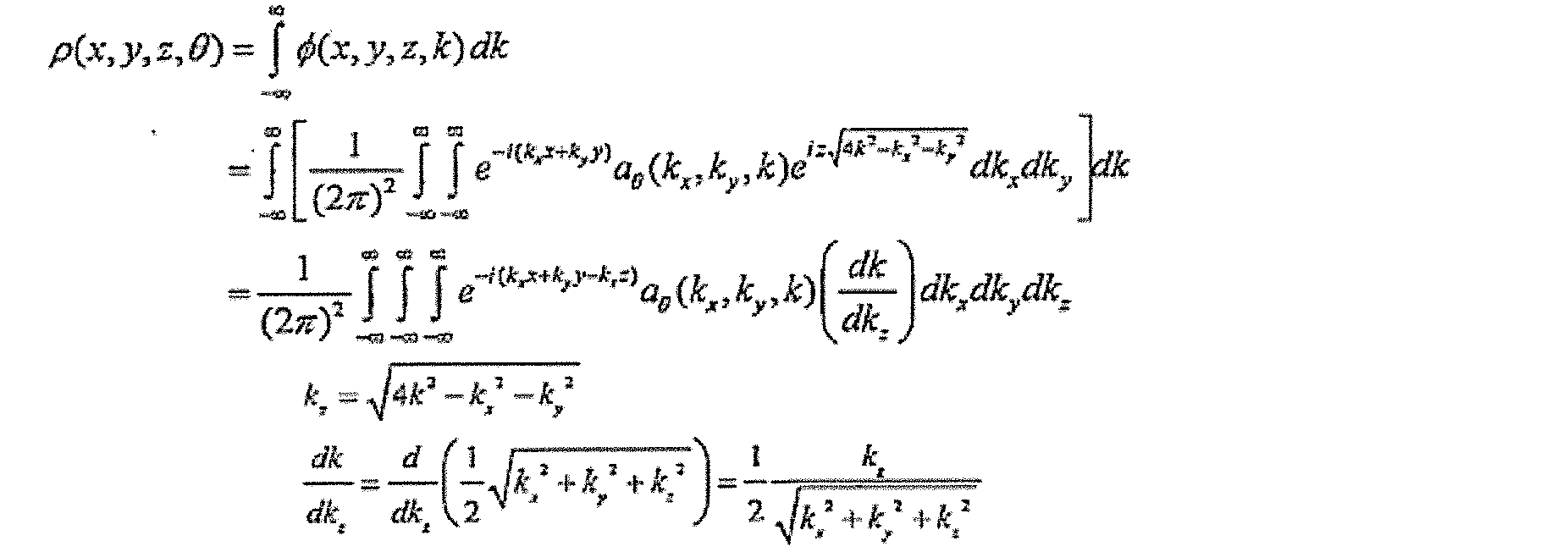

ここで、xは前記送信点および前記受信点の位置のx座標であり、yは前記送信点および前記受信点の位置のy座標であり、zは前記送信点および前記受信点の位置のz座標であり、(X,Y,Z)は前記略円錐の頂点を原点とし、前記原点から前記略円錐の底面の中心に向かう方向をZ方向とし、前記底面に平行で前記原点を通る方向をX方向とし、前記底面に平行で前記原点を通り前記X方向と直交する方向をY方向としたときの座標であり、ρは誘電率の関数であり、φは前記再構成関数であり、aθは係数であり、kx、ky、kzは波数のx、y、z成分であり、kは時間の波数であり、θは前記略円錐の軸を回転軸とする回転角度である。
前記映像化関数は、ξ、η、およびζがそれぞれ以下の(式E)を満たす変数であるとき以下の(式F)により表され、
前記画像再構成部は、前記映像化関数をθで積分することにより得られる以下の(式G)により表される関数を用いて前記対象物の内部情報に関する画像を再構成してもよい。
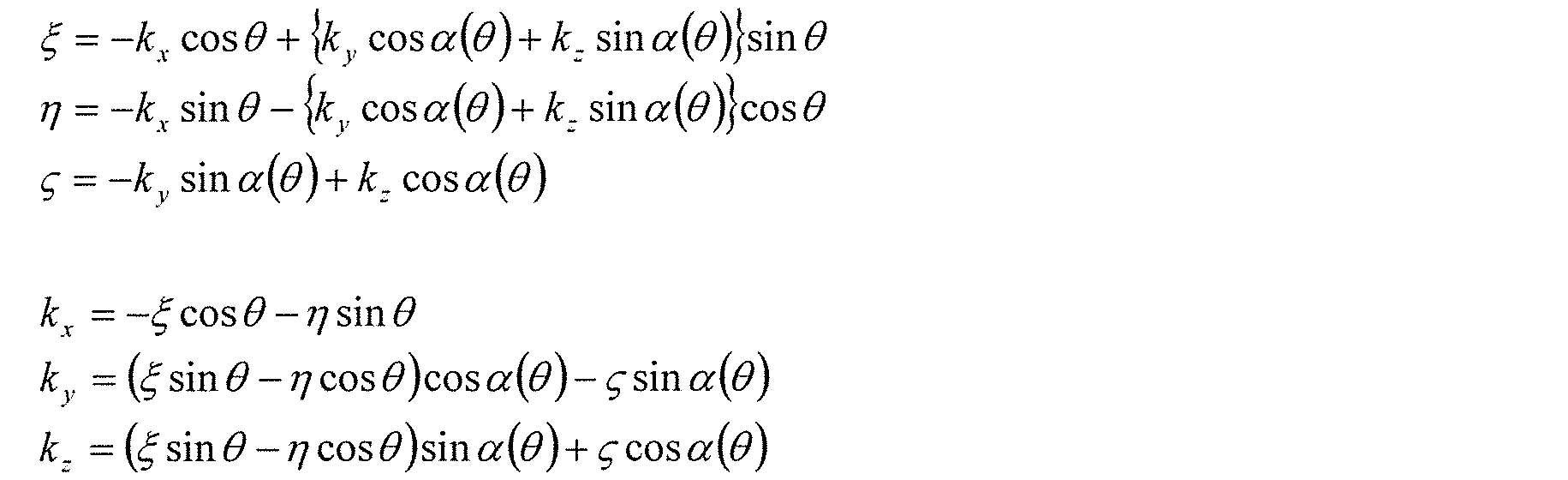


ここで、xは前記送信点および前記受信点の位置のx座標であり、yは前記送信点および前記受信点の位置のy座標であり、zは前記送信点および前記受信点の位置のz座標であり、(X,Y,Z)は前記錐体の頂点を原点とし、前記原点から前記錐体の底面の中心に向かう方向をZ方向とし、前記底面に平行で前記原点を通る方向をX方向とし、前記底面に平行で前記原点を通り前記X方向と直交する方向をY方向としたときの座標であり、ρは誘電率の関数であり、φは前記再構成関数であり、φRはφ=φRδ(x)が成り立つ関数であり、aθは係数であり、kx、ky、kzは波数のx、y、z成分であり、kは時間の波数であり、θは前記錐体の軸を回転軸とする回転角度であり、αは前記Z方向を基準とした傾き角度である。
前記受信アンテナ素子と前記送信アンテナ素子との間には電波吸収手段が位置してもよい。
前記送信アンテナ素子および前記受信アンテナ素子は、一体となって前記対象物のうち円錐の母線に相当する線に沿って移動されてもよい。
前記送信アンテナ素子および前記受信アンテナ素子は、一体となって前記対象物のうち略円錐の曲線状の母線に相当する線に沿って移動されてもよい。
前記送信アンテナ素子および前記受信アンテナ素子は、一体となって前記対象物のうち非対称の錐体の母線に相当する線に沿って移動されてもよい。
本発明に係る実施の形態について説明する前に、本発明の基礎となった技術について説明する。
<検査装置の構成>
以下、実施の形態1にかかる検査装置の構成について、図1~3を用いて説明する。本実施の形態では、生体の内部情報、特に、欠陥組織の位置情報を映像化する例として、直線状の母線を持つ円錐体をモデルとする。具体的には、検査装置としてマンモグラフィ装置を、略円錐状の形状を有する対象物として乳房を、欠陥組織として乳房における癌組織を例として説明する。また、この装置において、センサ素子であるプローブを構成する送信アンテナ素子および受信アンテナ素子は、円錐体の母線に沿って移動されるものである。すなわち、送信アンテナ素子および受信アンテナ素子は、一体となって対象物のうち円錐の母線に相当する線に沿って移動される。ここで、円錐の母線に相当する線とは、対象物10の形状を円錐とみなしたとき、その円錐の母線に相当する線である。
図4は、図1に示した本実施の形態にかかるマンモグラフィ装置1の動作を示すフローチャート図である。
図5~図7は、本実施の形態に係る散乱トモグラフィ方法の原理を説明するための解析モデルである。
図5により、点r1から出た波動が点ξで反射して点r2へ戻ってくる状況を考える。ここで、本実施の形態にかかるマンモグラフィ装置1では、点r1と点r2とは同一の位置である。周波数ωが一定という条件で、波動の送信点r1と受信点r2がx断面D(円錐体60aの側面)の内部を自由に動く。このとき得られるデータをG(r1,r2,ω)と書くと、この関数は領域内の反射点の分布に関係したものとなる。ここで、ωは角周波数であり、ω=2πfである。G(r1,r2,ω)は、全ての点ξからの反射信号の和であり、領域内には多くの反射点があるので、G(r1,r2,ω)は次の(式1)のように書くことができる。



次に、上記した微分作用素を求める方法について説明する。図6および図7は、微分作用素を求める方法について説明するための解析モデルである。



























上記したマンモグラフィ装置1により再構成画像を得ることの効果について、説明する。
次に、本発明の実施の形態2について説明する。
図10および図11は、本実施の形態に係る散乱トモグラフィ方法の原理を説明するための解析モデルである。以下、図10および図11に示すモデルを解析モデルとして、本実施の形態にかかるマンモグラフィ装置の映像化関数の導出について説明する。
図10により、点r1から出た波動が点ξで反射して点r2へ戻ってくる状況を考える。ここで、本実施の形態にかかるマンモグラフィ装置1では、点r1と点r2とは同一の位置である。周波数ωが一定という条件で、波動の送信点r1と受信点r2がある拘束条件を満たしながら曲面(円錐体60bの側面)上を自由に動く。このとき得られるデータをG(r1,r2,ω)と書くと、この関数は領域内の反射点の分布に関係したものとなる。このとき、ωは角周波数=2πfである。G(r1,r2,ω)は、全ての点ξからの反射信号の和であり、領域内に多くの反射点があるので、G(r1,r2,ω)は、実施の形態1に示した(式1)と同様に考えることができる。
以下、この微分作用素を求める方法について述べる。本実施の形態に係る解析モデルでは、図10および図11に示したように、実施の形態1の解析モデルにおける円錐体の母線が曲線状であり、この曲線状の母線に沿って、送信アンテナおよび受信アンテナが移動する。そして、アンテナアレイが、Z軸を中心に回転移動もしてもよい。曲線状の母線の上ではr1、r2のx、y、z座標は、r1=(x,y1,z1)(=(x,y,z))、r2=(x,y2,z2)(=(x,y,z))と表される。

































次に、実施の形態3について説明する。本実施の形態にかかるマンモグラフィ装置が実施の形態1に係るマンモグラフィ装置1と異なる点は、非対称の円錐状の形状を有する対象物を解析モデルとしている点である。


以上、本発明に係る検査装置および検査方法として、マンモグラフィを例として、複数の実施の形態に基づいて説明したが、本発明は実施の形態に限定されるものではない。実施の形態に対して当業者が思いつく変形を施して得られる形態、および、複数の実施の形態における構成要素を任意に組み合わせて実現される別の形態も本発明に含まれる。
1-1. 対象物に対して放射した波動の散乱波を解析して前記対象物の内部状態を検査する検査方法であって、
前記対象物に当接して前記対象物に波動を放射する送信アンテナ素子によって、前記波動を前記対象物に放射するステップと、
前記送信アンテナ素子と一体に設けられ、前記対象物に当接して、前記送信アンテナ素子から送信された前記波動が前記対象物において散乱した散乱波を受信する受信アンテナ素子によって、前記散乱波を受信するステップと、
前記受信アンテナ素子により受信した散乱波を示す散乱波データから、前記対象物の内部情報に関する画像を再構成するステップとを含み、
前記画像を再構成するステップにおいて、
前記対象物の内部情報に関する画像を再構成するための再構成関数を、前記対象物と同一の形状を有する3次元空間を対象としてあらかじめ設定し、
前記再構成関数の漸近式が満たす偏微分方程式を構築し、
前記散乱波データから、前記偏微分方程式を解くことにより得られる映像化関数を導出し、
前記映像化関数により、前記対象物の内部情報に関する画像を再構成する
検査方法。
1-2. 前記対象物は、円錐状の形状を有し、
前記送信アンテナ素子および前記受信アンテナ素子は、一体となって前記対象物の円錐の母線に沿って移動される
1-1.に記載の検査方法。
1-3. 前記対象物は、曲線状の母線を有する略円錐状の形状を有し、
前記送信アンテナ素子および前記受信アンテナ素子は、一体となって前記曲線状の母線に沿って移動される
1-1.に記載の検査方法。
1-4. 前記対象物は、非対称の錐体の形状を有し、
前記送信アンテナ素子および前記受信アンテナ素子は、一体となって前記非対称の錐体の形状の母線に沿って移動する
1-1.に記載の検査方法。
1-5. 前記波動は、マイクロ波である
1-1.から1-4.のいずれか1つに記載の検査方法。
1-6. 前記波動は、パルス波または所定の周波数を有する周期波である
1-1.から1-4.のいずれか1つに記載の検査方法。
2-1. 対象物に対して放射した波動の散乱波を解析して前記対象物の内部状態を検査する検査装置であって、
前記対象物に当接し前記波動を前記対象物に放射する送信アンテナ素子と、
前記送信アンテナ素子と一体に設けられ、前記対象物に当接して前記送信アンテナ素子から放射された前記波動が前記対象物において散乱した散乱波を受信する受信アンテナ素子と、
前記受信アンテナ素子により受信した散乱波を示す散乱波データから、前記対象物の内部情報に関する画像を再構成する画像再構成部とを備え、
前記画像再構成部は、
前記対象物の内部情報に関する画像を再構成するための再構成関数を、前記対象物と同一の形状を有する3次元空間を対象としてあらかじめ設定し、
前記再構成関数の漸近式が満たす偏微分方程式を構築し、
前記散乱波データから、前記偏微分方程式を解くことにより得られる映像化関数を導出し、
前記映像化関数により、前記対象物の内部情報に関する画像を再構成する
検査装置。
2-2. 前記対象物は、円錐状の形状を有し、
前記送信アンテナ素子および前記受信アンテナ素子は、一体となって前記対象物の円錐の母線に沿って移動される
2-1.に記載の検査装置。
2-3. 前記対象物は、曲線状の母線を有する略円錐状の形状を有し、
前記送信アンテナ素子および前記受信アンテナ素子は、一体となって前記曲線状の母線に沿って移動される
2-1.に記載の検査装置。
2-4. 前記対象物は、非対称の錐体の形状を有し、
前記送信アンテナ素子および前記受信アンテナ素子は、一体となって前記非対称の錐体の形状の母線に沿って移動する
2-1.に記載の検査装置。
2-5. 前記波動は、マイクロ波である
2-1.から2-4.のいずれか1つに記載の検査装置。
2-6. 前記波動は、パルス波または所定の周波数を有する周期波である
2-1.から2-4.のいずれか1つに記載の検査装置。
Claims (22)
- 波動を対象物に放射するステップと、
前記波動が前記対象物において散乱した散乱波を受信するステップと、
前記散乱波を示す散乱波データから、前記対象物の内部情報に関する画像を再構成するステップとを含み、
前記画像を再構成するステップにおいて、
前記散乱波データと形状を示す解析モデルとを用いて偏微分方程式を解くことにより、前記対象物の内部情報に関する画像を再構成するための再構成関数を導出し、
前記再構成関数を用いて、前記対象物の内部情報に関する画像を再構成し、
前記偏微分方程式は、前記再構成関数が満たす方程式である
画像化方法。 - 前記偏微分方程式は、
前記対象物内の送信点および受信点の位置を示す独立変数を用いて表され、
前記独立変数の数と同一の次元を持つ空間における各点において、前記散乱波が生じている場の関数である散乱場関数が解となる線形偏微分方程式であり、
前記画像を再構成するステップでは、前記再構成関数の時間変数の極限値である映像化関数を導出し、前記映像化関数を用いて前記対象物の内部情報に関する画像を再構成する請求項1に記載の画像化方法。 - 前記解析モデルが示す形状は円錐であり、
前記映像化関数は、以下の(式A)により表され、
前記画像を再構成するステップでは、前記映像化関数をθで積分することにより得られる以下の(式B)により表される関数を用いて前記対象物の内部情報に関する画像を再構成する請求項2に記載の画像化方法。


ここで、xは前記送信点および前記受信点の位置のx座標であり、yは前記送信点および前記受信点の位置のy座標であり、zは前記送信点および前記受信点の位置のz座標であり、(X,Y,Z)は前記円錐の頂点を原点とし、前記原点から前記円錐の底面の中心に向かう方向をZ方向とし、前記底面に平行で前記原点を通る方向をX方向とし、前記底面に平行で前記原点を通り前記X方向と直交する方向をY方向としたときの座標であり、ρは誘電率の関数であり、φは前記再構成関数であり、φRはφ=φRδ(x)が成り立つ関数であり、kx、ky、kzは波数のx、y、z成分であり、kは時間の波数であり、θは前記円錐の軸を回転軸とする回転角度である。 - 前記解析モデルが示す形状は曲線状の母線を有する略円錐であり、
前記映像化関数は、以下の(式C)により表され、
前記画像を再構成するステップでは、前記映像化関数をθで積分することにより得られる以下の(式D)により表される関数を用いて前記対象物の内部情報に関する画像を再構成する請求項2に記載の画像化方法。
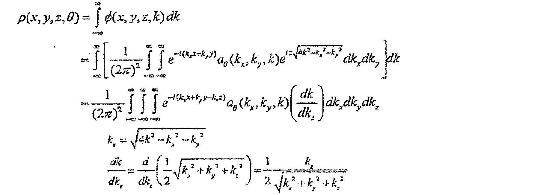

ここで、xは前記送信点および前記受信点の位置のx座標であり、yは前記送信点および前記受信点の位置のy座標であり、zは前記送信点および前記受信点の位置のz座標であり、(X,Y,Z)は前記略円錐の頂点を原点とし、前記原点から前記略円錐の底面の中心に向かう方向をZ方向とし、前記底面に平行で前記原点を通る方向をX方向とし、前記底面に平行で前記原点を通り前記X方向と直交する方向をY方向としたときの座標であり、ρは誘電率の関数であり、φは前記再構成関数であり、aθは係数であり、kx、ky、kzは波数のx、y、z成分であり、kは時間の波数であり、θは前記略円錐の軸を回転軸とする回転角度である。 - 前記解析モデルが示す形状は非対称の錐体であり、
前記映像化関数は、ξ、η、およびζがそれぞれ以下の(式E)を満たす変数であるとき以下の(式F)により表され、
前記画像を再構成するステップでは、前記映像化関数をθで積分することにより得られる以下の(式G)により表される関数を用いて前記対象物の内部情報に関する画像を再構成する請求項2に記載の画像化方法。



ここで、xは前記送信点および前記受信点の位置のx座標であり、yは前記送信点および前記受信点の位置のy座標であり、zは前記送信点および前記受信点の位置のz座標であり、(X,Y,Z)は前記錐体の頂点を原点とし、前記原点から前記錐体の底面の中心に向かう方向をZ方向とし、前記底面に平行で前記原点を通る方向をX方向とし、前記底面に平行で前記原点を通り前記X方向と直交する方向をY方向としたときの座標であり、ρは誘電率の関数であり、φは前記再構成関数であり、φRはφ=φRδ(x)が成り立つ関数であり、aθは係数であり、kx、ky、kzは波数のx、y、z成分であり、kは時間の波数であり、θは前記錐体の軸を回転軸とする回転角度であり、αは前記Z方向を基準とした傾き角度である。 - 前記放射するステップでは、前記散乱波を受信する受信アンテナ素子と前記対象物に前記波動を放射する送信アンテナ素子とが一体に設けられ、前記受信アンテナ素子と前記送信アンテナ素子との間に電波吸収手段が位置しているプローブを用いて前記波動を前記対象物に放射し、
前記受信するステップでは、前記プローブを用いて前記散乱波を受信する請求項1または2に記載の画像化方法。 - 前記解析モデルが示す形状は円錐であり、
前記送信アンテナ素子および前記受信アンテナ素子は、一体となって前記対象物のうち円錐の母線に相当する線に沿って移動される
請求項6に記載の画像化方法。 - 前記解析モデルが示す形状は、曲線状の母線を有する略円錐であり、
前記送信アンテナ素子および前記受信アンテナ素子は、一体となって前記対象物のうち略円錐の曲線状の母線に相当する線に沿って移動される
請求項6に記載の画像化方法。 - 前記解析モデルが示す形状は非対称の錐体であり、
前記送信アンテナ素子および前記受信アンテナ素子は、一体となって前記対象物のうち非対称の錐体の母線に相当する線に沿って移動される
請求項6に記載の画像化方法。 - 前記波動は、マイクロ波である
請求項1~9のいずれか1項に記載の画像化方法。 - 前記波動は、パルス波または所定の周波数を有する周期波である
請求項1~10のいずれか1項に記載の画像化方法。 - 波動を対象物に放射する送信アンテナ素子と、
前記送信アンテナ素子から放射された前記波動が前記対象物において散乱した散乱波を受信する受信アンテナ素子と、
前記受信アンテナ素子により受信した散乱波を示す散乱波データから、前記対象物の内部情報に関する画像を再構成する画像再構成部とを備え、
前記画像再構成部は、
前記散乱波データと形状を示す解析モデルとを用いて偏微分方程式を解くことにより、前記対象物の内部情報に関する画像を再構成するための再構成関数を導出し、
前記再構成関数を用いて、前記対象物の内部情報に関する画像を再構成し、
前記偏微分方程式は、前記再構成関数が満たす方程式である
画像化装置。 - 前記偏微分方程式は、
前記対象物内の送信点および受信点の位置を示す独立変数を用いて表され、
前記独立変数の数と同一の次元を持つ空間における各点において、前記散乱波が生じている場の関数である散乱場関数が解となる線形偏微分方程式であり、
前記画像再構成部は、前記再構成関数の時間変数の極限値である映像化関数を導出し、前記映像化関数を用いて前記対象物の内部情報に関する画像を再構成する請求項12に記載の画像化装置。 - 前記解析モデルが示す形状は円錐であり、
前記映像化関数は、以下の(式A)により表され、
前記画像再構成部は、前記映像化関数をθで積分することにより得られる以下の(式B)により表される関数を用いて前記対象物の内部情報に関する画像を再構成する請求項13に記載の画像化装置。


ここで、xは前記送信点および前記受信点の位置のx座標であり、yは前記送信点および前記受信点の位置のy座標であり、zは前記送信点および前記受信点の位置のz座標であり、(X,Y,Z)は前記円錐の頂点を原点とし、前記原点から前記円錐の底面の中心に向かう方向をZ方向とし、前記底面に平行で前記原点を通る方向をX方向とし、前記底面に平行で前記原点を通り前記X方向と直交する方向をY方向としたときの座標であり、ρは誘電率の関数であり、φは前記再構成関数であり、φRはφ=φRδ(x)が成り立つ関数であり、kx、ky、kzは波数のx、y、z成分であり、kは時間の波数であり、θは前記円錐の軸を回転軸とする回転角度である。 - 前記解析モデルが示す形状は曲線状の母線を有する略円錐であり、
前記映像化関数は、以下の(式C)により表され、
前記画像再構成部は、前記映像化関数をθで積分することにより得られる以下の(式D)により表される関数を用いて前記対象物の内部情報に関する画像を再構成する請求項13に記載の画像化装置。


ここで、xは前記送信点および前記受信点の位置のx座標であり、yは前記送信点および前記受信点の位置のy座標であり、zは前記送信点および前記受信点の位置のz座標であり、(X,Y,Z)は前記略円錐の頂点を原点とし、前記原点から前記略円錐の底面の中心に向かう方向をZ方向とし、前記底面に平行で前記原点を通る方向をX方向とし、前記底面に平行で前記原点を通り前記X方向と直交する方向をY方向としたときの座標であり、ρは誘電率の関数であり、φは前記再構成関数であり、aθは係数であり、kx、ky、kzは波数のx、y、z成分であり、kは時間の波数であり、θは前記略円錐の軸を回転軸とする回転角度である。 - 前記解析モデルが示す形状は非対称の錐体であり、
前記映像化関数は、ξ、η、およびζがそれぞれ以下の(式E)を満たす変数であるとき以下の(式F)により表され、
前記画像再構成部は、前記映像化関数をθで積分することにより得られる以下の(式G)により表される関数を用いて前記対象物の内部情報に関する画像を再構成する請求項13に記載の画像化装置。


ここで、xは前記送信点および前記受信点の位置のx座標であり、yは前記送信点および前記受信点の位置のy座標であり、zは前記送信点および前記受信点の位置のz座標であり、(X,Y,Z)は前記錐体の頂点を原点とし、前記原点から前記錐体の底面の中心に向かう方向をZ方向とし、前記底面に平行で前記原点を通る方向をX方向とし、前記底面に平行で前記原点を通り前記X方向と直交する方向をY方向としたときの座標であり、ρは誘電率の関数であり、φは前記再構成関数であり、φRはφ=φRδ(x)が成り立つ関数であり、aθは係数であり、kx、ky、kzは波数のx、y、z成分であり、kは時間の波数であり、θは前記錐体の軸を回転軸とする回転角度であり、αは前記Z方向を基準とした傾き角度である。 - 前記受信アンテナ素子と前記送信アンテナ素子とが一体に設けられたプローブをさらに備え、
前記受信アンテナ素子と前記送信アンテナ素子との間には電波吸収手段が位置する請求項12または13に記載の画像化装置。 - 前記解析モデルが示す形状は円錐であり、
前記送信アンテナ素子および前記受信アンテナ素子は、一体となって前記対象物のうち円錐の母線に相当する線に沿って移動される
請求項17に記載の画像化装置。 - 前記解析モデルが示す形状は、曲線状の母線を有する略円錐であり、
前記送信アンテナ素子および前記受信アンテナ素子は、一体となって前記対象物のうち略円錐の曲線状の母線に相当する線に沿って移動される
請求項17に記載の画像化装置。 - 前記解析モデルが示す形状は非対称の錐体であり、
前記送信アンテナ素子および前記受信アンテナ素子は、一体となって前記対象物のうち非対称の錐体の母線に相当する線に沿って移動される
請求項17に記載の画像化装置。 - 前記波動は、マイクロ波である
請求項12~20のいずれか1項に記載の画像化装置。 - 前記波動は、パルス波または所定の周波数を有する周期波である
請求項12~21のいずれか1項に記載の画像化装置。
Priority Applications (7)
| Application Number | Priority Date | Filing Date | Title |
|---|---|---|---|
| JP2017543529A JP6752473B2 (ja) | 2015-09-29 | 2016-09-28 | 画像化方法および画像化装置 |
| ES16851695T ES2918590T3 (es) | 2015-09-29 | 2016-09-28 | Método de obtención de imágenes y aparato de obtención de imágenes |
| CN201680059162.XA CN108139340B (zh) | 2015-09-29 | 2016-09-28 | 图像化方法以及图像化装置 |
| US15/764,091 US10586354B2 (en) | 2015-09-29 | 2016-09-28 | Imaging method and imaging apparatus |
| DK16851695.3T DK3358338T3 (da) | 2015-09-29 | 2016-09-28 | Billeddannelsesfremgangsmåde og billeddannelsesapparat |
| PL16851695T PL3358338T3 (pl) | 2015-09-29 | 2016-09-28 | Sposób obrazowania i aparat obrazujący |
| EP16851695.3A EP3358338B1 (en) | 2015-09-29 | 2016-09-28 | Imaging method and imaging apparatus |
Applications Claiming Priority (2)
| Application Number | Priority Date | Filing Date | Title |
|---|---|---|---|
| JP2015-192216 | 2015-09-29 | ||
| JP2015192216 | 2015-09-29 |
Publications (1)
| Publication Number | Publication Date |
|---|---|
| WO2017057524A1 true WO2017057524A1 (ja) | 2017-04-06 |
Family
ID=58427491
Family Applications (1)
| Application Number | Title | Priority Date | Filing Date |
|---|---|---|---|
| PCT/JP2016/078742 Ceased WO2017057524A1 (ja) | 2015-09-29 | 2016-09-28 | 画像化方法および画像化装置 |
Country Status (10)
| Country | Link |
|---|---|
| US (1) | US10586354B2 (ja) |
| EP (1) | EP3358338B1 (ja) |
| JP (1) | JP6752473B2 (ja) |
| CN (1) | CN108139340B (ja) |
| DK (1) | DK3358338T3 (ja) |
| ES (1) | ES2918590T3 (ja) |
| HU (1) | HUE059413T2 (ja) |
| PL (1) | PL3358338T3 (ja) |
| PT (1) | PT3358338T (ja) |
| WO (1) | WO2017057524A1 (ja) |
Cited By (12)
| Publication number | Priority date | Publication date | Assignee | Title |
|---|---|---|---|---|
| WO2020059861A1 (ja) | 2018-09-20 | 2020-03-26 | 凸版印刷株式会社 | 検査用シール |
| JP2020092737A (ja) * | 2018-12-10 | 2020-06-18 | 凸版印刷株式会社 | 検査用シール |
| JP2020092769A (ja) * | 2018-12-11 | 2020-06-18 | 凸版印刷株式会社 | 検査用シール |
| JP2020168348A (ja) * | 2018-09-20 | 2020-10-15 | 凸版印刷株式会社 | 検査用シール |
| JP2020174936A (ja) * | 2019-04-19 | 2020-10-29 | 凸版印刷株式会社 | 検査用シール |
| JP2020178930A (ja) * | 2019-04-25 | 2020-11-05 | 凸版印刷株式会社 | 検査用シール |
| WO2021020387A1 (ja) * | 2019-08-01 | 2021-02-04 | 株式会社 Integral Geometry Science | 散乱トモグラフィ装置及び散乱トモグラフィ方法 |
| JPWO2021053971A1 (ja) * | 2019-09-17 | 2021-03-25 | ||
| WO2021112222A1 (ja) * | 2019-12-06 | 2021-06-10 | 凸版印刷株式会社 | 補助シール、および、検査用シールセット |
| JPWO2022260112A1 (ja) * | 2021-06-11 | 2022-12-15 | ||
| WO2022265017A1 (ja) * | 2021-06-17 | 2022-12-22 | 建次郎 木村 | 映像化装置及び映像化方法 |
| WO2024116762A1 (ja) * | 2022-11-29 | 2024-06-06 | 建次郎 木村 | 映像化装置及び映像化方法 |
Families Citing this family (5)
| Publication number | Priority date | Publication date | Assignee | Title |
|---|---|---|---|---|
| JP6938812B2 (ja) * | 2017-02-24 | 2021-09-22 | 株式会社三井E&Sマシナリー | データ処理方法及び計測装置 |
| JP7319255B2 (ja) * | 2017-06-08 | 2023-08-01 | エムビジョン メディカル デバイセズ リミテッド | 断層画像プロセス、コンピュータ読み取り可能記憶媒体、および断層画像システム |
| US11237103B2 (en) * | 2018-05-31 | 2022-02-01 | Socovar Sec | Electronic device testing system, electronic device production system including same and method of testing an electronic device |
| US11888233B2 (en) * | 2020-04-07 | 2024-01-30 | Ramot At Tel-Aviv University Ltd | Tailored terahertz radiation |
| WO2025054721A1 (en) * | 2023-09-12 | 2025-03-20 | Wave View Imaging Inc. | Method and system for determining positioning configuration of antennas used in scanning biological tissue |
Citations (1)
| Publication number | Priority date | Publication date | Assignee | Title |
|---|---|---|---|---|
| WO2015136936A1 (ja) * | 2014-03-12 | 2015-09-17 | 国立大学法人神戸大学 | 散乱トモグラフィ方法および散乱トモグラフィ装置 |
Family Cites Families (15)
| Publication number | Priority date | Publication date | Assignee | Title |
|---|---|---|---|---|
| DE3224453A1 (de) * | 1982-06-30 | 1984-01-05 | Siemens AG, 1000 Berlin und 8000 München | Ultraschall-tomographiegeraet |
| DE3531893A1 (de) * | 1985-09-06 | 1987-03-19 | Siemens Ag | Verfahren zur bestimmung der verteilung der dielektrizitaetskonstanten in einem untersuchungskoerper sowie messanordnung zur durchfuehrung des verfahrens |
| US5363050A (en) * | 1990-08-31 | 1994-11-08 | Guo Wendy W | Quantitative dielectric imaging system |
| US5859609A (en) * | 1991-08-30 | 1999-01-12 | Battelle Memorial Institute | Real-time wideband cylindrical holographic surveillance system |
| US5588032A (en) * | 1992-10-14 | 1996-12-24 | Johnson; Steven A. | Apparatus and method for imaging with wavefields using inverse scattering techniques |
| US6876878B2 (en) | 1996-06-26 | 2005-04-05 | University Of Utah Research Foundation | Medical broad band electromagnetic holographic imaging |
| US7840249B2 (en) * | 2004-11-24 | 2010-11-23 | University Of Iowa Research Foundation | Clinical micro-CT (CMCT) methods, techniques and apparatus |
| EP2012139A1 (en) * | 2007-07-06 | 2009-01-07 | Sensino Limited | Body monitoring apparatus and method |
| DE102009007255A1 (de) * | 2008-06-02 | 2009-12-03 | Rohde & Schwarz Gmbh & Co. Kg | Brustkrebserkennung mit Fixierungstrichter |
| JP5197461B2 (ja) * | 2009-03-27 | 2013-05-15 | 三井造船株式会社 | 対象物中の誘電率算出装置及び誘電率算出方法 |
| WO2010143691A1 (ja) * | 2009-06-10 | 2010-12-16 | 国立大学法人静岡大学 | 診断装置 |
| JP5638827B2 (ja) * | 2010-04-02 | 2014-12-10 | 古河電気工業株式会社 | 内蔵型レーダ用送受一体アンテナ |
| US9329263B2 (en) * | 2011-05-23 | 2016-05-03 | The Regents Of The University Of Michigan | Imaging system and method |
| WO2014125815A1 (ja) * | 2013-02-12 | 2014-08-21 | 国立大学法人神戸大学 | 散乱トモグラフィ方法および散乱トモグラフィ装置 |
| JP2014198067A (ja) * | 2013-03-29 | 2014-10-23 | 国立大学法人静岡大学 | 診断装置 |
-
2016
- 2016-09-28 CN CN201680059162.XA patent/CN108139340B/zh active Active
- 2016-09-28 US US15/764,091 patent/US10586354B2/en active Active
- 2016-09-28 PL PL16851695T patent/PL3358338T3/pl unknown
- 2016-09-28 WO PCT/JP2016/078742 patent/WO2017057524A1/ja not_active Ceased
- 2016-09-28 ES ES16851695T patent/ES2918590T3/es active Active
- 2016-09-28 DK DK16851695.3T patent/DK3358338T3/da active
- 2016-09-28 EP EP16851695.3A patent/EP3358338B1/en active Active
- 2016-09-28 HU HUE16851695A patent/HUE059413T2/hu unknown
- 2016-09-28 JP JP2017543529A patent/JP6752473B2/ja active Active
- 2016-09-28 PT PT168516953T patent/PT3358338T/pt unknown
Patent Citations (1)
| Publication number | Priority date | Publication date | Assignee | Title |
|---|---|---|---|---|
| WO2015136936A1 (ja) * | 2014-03-12 | 2015-09-17 | 国立大学法人神戸大学 | 散乱トモグラフィ方法および散乱トモグラフィ装置 |
Cited By (33)
| Publication number | Priority date | Publication date | Assignee | Title |
|---|---|---|---|---|
| CN112996438A (zh) * | 2018-09-20 | 2021-06-18 | 凸版印刷株式会社 | 检查用贴片 |
| JP7351162B2 (ja) | 2018-09-20 | 2023-09-27 | 凸版印刷株式会社 | 検査用シール |
| JP2020168348A (ja) * | 2018-09-20 | 2020-10-15 | 凸版印刷株式会社 | 検査用シール |
| US12551314B2 (en) | 2018-09-20 | 2026-02-17 | Toppan Printing Co., Ltd. | Examination marker |
| WO2020059861A1 (ja) | 2018-09-20 | 2020-03-26 | 凸版印刷株式会社 | 検査用シール |
| JP7107200B2 (ja) | 2018-12-10 | 2022-07-27 | 凸版印刷株式会社 | 検査用シール |
| JP2020092737A (ja) * | 2018-12-10 | 2020-06-18 | 凸版印刷株式会社 | 検査用シール |
| JP2020092769A (ja) * | 2018-12-11 | 2020-06-18 | 凸版印刷株式会社 | 検査用シール |
| JP7107201B2 (ja) | 2018-12-11 | 2022-07-27 | 凸版印刷株式会社 | 検査用シール |
| JP2020174936A (ja) * | 2019-04-19 | 2020-10-29 | 凸版印刷株式会社 | 検査用シール |
| JP7147674B2 (ja) | 2019-04-19 | 2022-10-05 | 凸版印刷株式会社 | 検査用シール |
| JP7183938B2 (ja) | 2019-04-25 | 2022-12-06 | 凸版印刷株式会社 | 検査用シール |
| JP2020178930A (ja) * | 2019-04-25 | 2020-11-05 | 凸版印刷株式会社 | 検査用シール |
| JP7464293B2 (ja) | 2019-08-01 | 2024-04-09 | 株式会社 Integral Geometry Science | 散乱トモグラフィ装置及び散乱トモグラフィ方法 |
| JPWO2021020387A1 (ja) * | 2019-08-01 | 2021-02-04 | ||
| WO2021020387A1 (ja) * | 2019-08-01 | 2021-02-04 | 株式会社 Integral Geometry Science | 散乱トモグラフィ装置及び散乱トモグラフィ方法 |
| JPWO2021053971A1 (ja) * | 2019-09-17 | 2021-03-25 | ||
| TWI837407B (zh) * | 2019-09-17 | 2024-04-01 | 日商積分幾何科學股份有限公司 | 散射斷層掃描裝置及散射斷層掃描方法 |
| WO2021053971A1 (ja) * | 2019-09-17 | 2021-03-25 | 株式会社 Integral Geometry Science | 散乱トモグラフィ装置及び散乱トモグラフィ方法 |
| US12505591B2 (en) | 2019-09-17 | 2025-12-23 | Integral Geometry Science Inc. | Scattering tomography device and scattering tomography method |
| KR102827018B1 (ko) | 2019-09-17 | 2025-07-01 | 가부시키가이샤 인테그랄 지오메트리 사이언스 | 산란 토모그래피 장치 및 산란 토모그래피 방법 |
| JP7481757B2 (ja) | 2019-09-17 | 2024-05-13 | 株式会社 Integral Geometry Science | 散乱トモグラフィ装置及び散乱トモグラフィ方法 |
| KR20220062270A (ko) * | 2019-09-17 | 2022-05-16 | 가부시키가이샤 인테그랄 지오메트리 사이언스 | 산란 토모그래피 장치 및 산란 토모그래피 방법 |
| WO2021112222A1 (ja) * | 2019-12-06 | 2021-06-10 | 凸版印刷株式会社 | 補助シール、および、検査用シールセット |
| JP7427943B2 (ja) | 2019-12-06 | 2024-02-06 | Toppanホールディングス株式会社 | 補助シール、および、検査用シールセット |
| JP2021090499A (ja) * | 2019-12-06 | 2021-06-17 | 凸版印刷株式会社 | 補助シール、および、検査用シールセット |
| WO2022260112A1 (ja) * | 2021-06-11 | 2022-12-15 | 株式会社 Integral Geometry Science | 映像化装置及び映像化方法 |
| JP7813474B2 (ja) | 2021-06-11 | 2026-02-13 | 株式会社 Integral Geometry Science | 映像化装置及び映像化方法 |
| JPWO2022260112A1 (ja) * | 2021-06-11 | 2022-12-15 | ||
| JPWO2022265017A1 (ja) * | 2021-06-17 | 2022-12-22 | ||
| WO2022265017A1 (ja) * | 2021-06-17 | 2022-12-22 | 建次郎 木村 | 映像化装置及び映像化方法 |
| JP7822636B2 (ja) | 2021-06-17 | 2026-03-03 | K-theory株式会社 | 映像化装置及び映像化方法 |
| WO2024116762A1 (ja) * | 2022-11-29 | 2024-06-06 | 建次郎 木村 | 映像化装置及び映像化方法 |
Also Published As
| Publication number | Publication date |
|---|---|
| DK3358338T3 (da) | 2022-06-20 |
| JP6752473B2 (ja) | 2020-09-09 |
| ES2918590T3 (es) | 2022-07-19 |
| JPWO2017057524A1 (ja) | 2018-08-02 |
| US20180308259A1 (en) | 2018-10-25 |
| HUE059413T2 (hu) | 2022-11-28 |
| PT3358338T (pt) | 2022-06-20 |
| CN108139340B (zh) | 2021-03-09 |
| EP3358338A4 (en) | 2019-06-12 |
| EP3358338B1 (en) | 2022-03-30 |
| CN108139340A (zh) | 2018-06-08 |
| PL3358338T3 (pl) | 2022-07-04 |
| US10586354B2 (en) | 2020-03-10 |
| EP3358338A1 (en) | 2018-08-08 |
Similar Documents
| Publication | Publication Date | Title |
|---|---|---|
| JP6752473B2 (ja) | 画像化方法および画像化装置 | |
| JP6468570B2 (ja) | 散乱トモグラフィ方法および散乱トモグラフィ装置 | |
| JP6557747B2 (ja) | 散乱トモグラフィ方法および散乱トモグラフィ装置 | |
| Gemmeke et al. | 3D ultrasound computer tomography for medical imaging | |
| US8977340B2 (en) | System and method for collection and use of magnetic resonance data and microwave data to identify boundaries of interest | |
| EP4009861A1 (en) | Apparatus and process for electromagnetic imaging | |
| JP7212827B2 (ja) | 診断装置、トモグラフィ処理の実行方法、診断プログラム | |
| WO2006006559A1 (ja) | ミリ波帯電磁波を用いた生体情報の獲得方法、生体情報を獲得して表示する装置 | |
| EP3239706A1 (en) | Apparatus and method for inspecting an object using ultrasonic waves in the field of material testing | |
| Eremeev et al. | Application of the migration method for radiotomography of breast cancer | |
| Goncharsky et al. | Artifacts of reconstructed images in inverse problems of ultrasound tomography in models with absorption | |
| Lalitha et al. | Design Of Uwb Vivaldi Antenna For Stroke Detection And Monitoring Based OnQualitative Microwave Imaging Technique. | |
| CN114173677A (zh) | 混合医学成像探针、设备及过程 | |
| Mensah et al. | Ultrasound mammography | |
| CN111954806A (zh) | 用于材料的介电不连续性的微波测量的设备 | |
| EREMEEV | METHODS OF DIAGNOSTICS OF BREAST CANCER BY USE OF RADIO MAMMOGRAPHY SERGEY SHIPILOV, RAIL SATAROV, ALEXANDER EREMEEV AND ILYA TSEPLYAEV | |
| Zuo et al. | Rapid High-Resolution Breast Imaging With Ring-Array Multi-Subarray Synthetic-Aperture Frequency-Domain Ultrasound Computed Tomography Method | |
| Addouma et al. | Three-dimensional frequency-domain optical anisotropy imaging of | |
| Zwiebel | Limited view sound speed imaging for breast cancer detection |
Legal Events
| Date | Code | Title | Description |
|---|---|---|---|
| 121 | Ep: the epo has been informed by wipo that ep was designated in this application |
Ref document number: 16851695 Country of ref document: EP Kind code of ref document: A1 |
|
| ENP | Entry into the national phase |
Ref document number: 2017543529 Country of ref document: JP Kind code of ref document: A |
|
| WWE | Wipo information: entry into national phase |
Ref document number: 15764091 Country of ref document: US |
|
| NENP | Non-entry into the national phase |
Ref country code: DE |
|
| WWE | Wipo information: entry into national phase |
Ref document number: 2016851695 Country of ref document: EP |