WO2017057166A1 - プレスラインの運転制御装置及び運転制御方法 - Google Patents
プレスラインの運転制御装置及び運転制御方法 Download PDFInfo
- Publication number
- WO2017057166A1 WO2017057166A1 PCT/JP2016/077960 JP2016077960W WO2017057166A1 WO 2017057166 A1 WO2017057166 A1 WO 2017057166A1 JP 2016077960 W JP2016077960 W JP 2016077960W WO 2017057166 A1 WO2017057166 A1 WO 2017057166A1
- Authority
- WO
- WIPO (PCT)
- Prior art keywords
- controller
- transport
- press
- press machine
- transport device
- Prior art date
Links
- 238000000034 method Methods 0.000 title claims description 49
- 230000032258 transport Effects 0.000 claims description 389
- 238000012546 transfer Methods 0.000 claims description 49
- 238000012545 processing Methods 0.000 claims description 27
- 238000012544 monitoring process Methods 0.000 claims description 23
- 230000005856 abnormality Effects 0.000 claims description 22
- 238000011144 upstream manufacturing Methods 0.000 description 80
- 230000008569 process Effects 0.000 description 34
- 238000004891 communication Methods 0.000 description 28
- 230000002159 abnormal effect Effects 0.000 description 12
- 238000010586 diagram Methods 0.000 description 11
- 230000003247 decreasing effect Effects 0.000 description 3
- 230000007246 mechanism Effects 0.000 description 3
- 238000013459 approach Methods 0.000 description 2
- 230000002452 interceptive effect Effects 0.000 description 2
- 238000003754 machining Methods 0.000 description 2
- 230000000630 rising effect Effects 0.000 description 2
- 230000007704 transition Effects 0.000 description 2
- 230000005540 biological transmission Effects 0.000 description 1
- 238000012937 correction Methods 0.000 description 1
- 230000000694 effects Effects 0.000 description 1
- 238000012986 modification Methods 0.000 description 1
- 230000004048 modification Effects 0.000 description 1
- 238000000465 moulding Methods 0.000 description 1
- 230000000007 visual effect Effects 0.000 description 1
Images


Classifications
-
- B—PERFORMING OPERATIONS; TRANSPORTING
- B21—MECHANICAL METAL-WORKING WITHOUT ESSENTIALLY REMOVING MATERIAL; PUNCHING METAL
- B21D—WORKING OR PROCESSING OF SHEET METAL OR METAL TUBES, RODS OR PROFILES WITHOUT ESSENTIALLY REMOVING MATERIAL; PUNCHING METAL
- B21D43/00—Feeding, positioning or storing devices combined with, or arranged in, or specially adapted for use in connection with, apparatus for working or processing sheet metal, metal tubes or metal profiles; Associations therewith of cutting devices
- B21D43/02—Advancing work in relation to the stroke of the die or tool
- B21D43/04—Advancing work in relation to the stroke of the die or tool by means in mechanical engagement with the work
- B21D43/05—Advancing work in relation to the stroke of the die or tool by means in mechanical engagement with the work specially adapted for multi-stage presses
-
- B—PERFORMING OPERATIONS; TRANSPORTING
- B30—PRESSES
- B30B—PRESSES IN GENERAL
- B30B13/00—Methods of pressing not special to the use of presses of any one of the preceding main groups
-
- B—PERFORMING OPERATIONS; TRANSPORTING
- B30—PRESSES
- B30B—PRESSES IN GENERAL
- B30B15/00—Details of, or accessories for, presses; Auxiliary measures in connection with pressing
- B30B15/14—Control arrangements for mechanically-driven presses
- B30B15/146—Control arrangements for mechanically-driven presses for synchronising a line of presses
-
- B—PERFORMING OPERATIONS; TRANSPORTING
- B30—PRESSES
- B30B—PRESSES IN GENERAL
- B30B15/00—Details of, or accessories for, presses; Auxiliary measures in connection with pressing
- B30B15/30—Feeding material to presses
-
- B—PERFORMING OPERATIONS; TRANSPORTING
- B30—PRESSES
- B30B—PRESSES IN GENERAL
- B30B15/00—Details of, or accessories for, presses; Auxiliary measures in connection with pressing
- B30B15/32—Discharging presses
Definitions
- the present invention relates to an operation control device and an operation control method for a press line.
- the host controller As a press line operation control method in which the press device and transport device are alternately arranged in the work transport direction, the host controller generates a command signal and transmits it to the controller of each device to control the press line.
- a method is known (for example, JP 2008-246529 A).
- the present invention has been made in view of the problems as described above, and an object of the present invention is to control an operation of a press line that can operate so that each device does not interfere without depending on a master signal. And providing an operation control method.
- An operation control device for a press line includes a first press machine, a first transport device that loads a workpiece before processing into the first press machine, and a workpiece after processing from the first press machine.
- An operation control device for a press line including a second transport device for unloading the first press machine, a first press controller for controlling the first press machine, a first transport controller for controlling the first transport device, and the first transport device.
- the first press controller, the first transport controller, and the second transport controller are communicably connected to each other, and the first transport controller is connected to the first transport controller.
- Time information indicating a timing at which the transfer device exits from the interference area with the first press machine (time until exit from the interference area or time from the interference area)
- the first press controller transmits the first press controller after the time (time) when the first transport device leaves the interference area based on the time information received from the first transport controller.
- the first press machine is controlled so that the slide of one press machine enters the interference area with the first transport device, and the timing at which the slide of the first press machine exits the interference area with the second transport device is shown.
- Time information is transmitted to the second transport controller, and the second transport controller is based on the time information received from the first press controller after the time when the slide of the first press machine exits the interference area.
- the second transport device is controlled so that the second transport device enters an interference area with the first press machine.
- the press line operation control method includes a first press machine, a first transport device for carrying a workpiece before machining into the first press machine, and a workpiece after machining from the first press machine.
- a second transport device a first press controller for controlling the first press machine, a first transport controller for controlling the first transport device, and a second transport controller for controlling the second transport device.
- a method for controlling operation of a press line wherein the first transport controller transmits time information indicating a timing at which the first transport device exits an interference area with the first press machine to the first press controller; Based on the time information received by the first press controller from the first transport controller, the first transport device exits the interference area.
- the first press machine is controlled such that the slide of the first press machine enters an interference area with the first transport device, and the slide of the first press machine has an interference area with the second transport device.
- the first press controller acquires time information indicating the timing at which the first transport device leaves the interference region from the first transport controller, and the slide is moved after the time when the first transport device leaves the interference region.
- the second transport controller obtains time information indicating the timing at which the slide exits the interference area from the first press controller, and the second transport apparatus performs the time after the slide exits the interference area.
- the second transport controller includes time information indicating a timing at which the second transport device exits from an interference area with the first transport device.
- the first transport controller transmits the first transport controller after the time when the second transport device leaves the interference area based on the time information received from the second transport controller. You may control a said 1st conveying apparatus so that it may enter into an interference area
- the first transport controller acquires time information indicating the timing at which the second transport device exits the interference area from the second transport controller, and the first transport controller starts after the time when the second transport apparatus exits the interference area.
- the first press controller moves the slide of the first press machine into an interference area with the first transport device at a predesignated speed. Controlling the first press machine to enter, and the second transfer controller controls the second transfer apparatus so that the second transfer apparatus enters an interference area with the first press machine at a predesignated speed.
- the first transport controller may control the first transport device so that the first transport device enters an interference region with the second transport device at a speed specified in advance.
- the timing at which the slide exits the interference area can be easily calculated, and the second transport device Is controlled so as to enter the interference region at a predesignated speed, the timing at which the second transport device exits the interference region can be easily calculated, and the first transport device can be at a predesignated speed.
- the press line further includes a second press machine and a second press controller for controlling the second press machine
- the second transport device includes the The work carried out from the first press machine is carried into the second press machine,
- the second transport controller and the second press controller may be connected to be communicable with each other.
- the second transport controller includes time information indicating a timing at which the second transport device comes out of an interference area with the second press machine. And the second press controller transmits the slide of the second press machine after the time when the second transport device leaves the interference area based on the time information received from the second transport controller. You may control the said 2nd press machine so that it may enter into an interference field with the 2nd conveyance device.
- the press line further includes a second press machine and a second press controller for controlling the second press machine
- the second transport device includes the first press machine.
- the work carried out from the press machine is carried into the second press machine, and the second transport controller receives time information indicating the timing at which the second transport device comes out of the interference area with the second press machine.
- the second press controller acquires time information indicating the timing at which the second transport device exits the interference area from the second transport controller, and the second press controller after the time when the second transport apparatus exits the interference area.
- the second press controller moves the slide of the second press machine into an interference region with the second transport device at a predesignated speed.
- the second press machine may be controlled to enter.
- the present invention it is possible to easily calculate the timing at which the slide of the second press machine exits the interference area by controlling the slide of the second press machine to enter the interference area at a predesignated speed. .
- the first transport controller is located in the plurality of operation sections obtained by dividing the operation of the first transport device.
- the section information indicating the operation section is updated, the updated section information is transmitted to the first press controller, and the second transport controller is configured to transmit the operation information of the second transport apparatus among the plurality of operation sections.
- 2 update the section information indicating the operation section in which the conveying device is located, and transmit the updated section information to the first press controller, and the first press controller divides the slide operation of the first press machine.
- the section information indicating the operation section where the slide of the first press machine is located is updated among the plurality of operation sections, and the updated section information and the first transport controller are updated.
- the state information indicating the state of the interference area is updated based on the controller and the section information received from the second transport controller, and the updated state information is transmitted to the first transport controller and the second transport controller.
- the slide area of the first press machine is in the shortest time (according to a preset press motion) and the interference area with the first transport device
- the first press machine is controlled to enter, and the state information is other than the case where there is a workpiece before processing, based on the time information received from the first transport controller, The first press machine so that the slide of the first press machine enters the interference area with the first transport apparatus after the time when the first transport apparatus leaves the interference area.
- the second transport device when the state information received from the first press controller indicates that there is a workpiece after processing, the second transport device is set in the shortest time (set in advance). The second transport device is controlled so as to enter an interference area with the first press machine (according to the transport motion), and the first information is in a case other than the case where the state information indicates that there is a processed workpiece. Based on the time information received from the press controller, the second conveying device enters the interference area with the first press machine after the time when the slide of the first press machine leaves the interference area.
- the first conveyance controller controls the conveyance device, and when the state information received from the first press controller indicates that there is no workpiece, the first conveyance controller Except when the apparatus controls the first transfer device so that the device enters the interference area with the second transfer device in the shortest time (according to a preset transfer motion), and the status information indicates that there is no workpiece In this case, based on the time information received from the second transport controller, the first transport device enters the interference region with the second transport device after the time when the second transport device leaves the interference region. In this way, the first transfer device may be controlled.
- the first press controller acquires section information indicating an operation section in which each transport apparatus is located from each transport controller, and determines an interference state based on the acquired section information and section information of the first press machine. Update the status information shown, send the updated status information to each transport controller, determine whether the first press controller and each transport controller are expected to generate interference based on the status information, and When the occurrence of the error is predicted, control based on the received time information is performed. As a result, each controller can grasp the interference state and reliably operate each device so as not to interfere.
- the first press controller monitors the first press machine for abnormality and monitors the time information received from the first transport controller.
- the second transport controller monitors the abnormality of the first transport device, and monitors the time information received from the first press controller. An abnormality of the first transport machine is monitored, the first transport controller monitors the abnormality of the first transport device, and the time information received from the second transport controller is monitored to detect an abnormality of the second transport device. May be monitored.
- the first press controller monitors not only the first press machine but also the first transport device
- the second transport controller monitors not only the second transport device but also the first press machine.
- the first transport controller monitors the abnormality of the second transport device as well as the first transport device, so that the abnormality can be detected quickly and the operation can be stopped.
- FIG. 1 is a diagram illustrating a configuration of a press line including an operation control device according to the present embodiment.
- FIG. 2 is a diagram for explaining the interference region.
- FIG. 3 is a diagram illustrating an operation trajectory of the transport device.
- FIG. 4 is a diagram illustrating an operation locus of the press machine.
- FIG. 5 is a functional block diagram illustrating the configuration of the transport controller.
- FIG. 6 is a functional block diagram showing the configuration of the press controller.
- FIG. 7 is a flowchart illustrating the flow of the linked operation process of the transport device.
- FIG. 8 is a flowchart illustrating the flow of the linked operation process of the transport device.
- FIG. 9 is a flowchart showing the flow of the linked operation end process of the transport device.
- FIG. 1 is a diagram illustrating a configuration of a press line including an operation control device according to the present embodiment.
- FIG. 2 is a diagram for explaining the interference region.
- FIG. 3 is a diagram illustrating an operation
- FIG. 10 is a flowchart showing a flow of processing for outputting the interference area departure time of the transfer device.
- FIG. 11 is a flowchart showing the flow of the linked operation processing of the press machine.
- FIG. 12 is a flowchart showing the flow of the linked operation end process of the press machine.
- FIG. 13 is a flowchart showing a flow of processing for outputting the interference area exit time of the press machine.
- FIG. 14 is a diagram illustrating an example of transition of variables generated by each of the upstream transport controller, the press controller, and the downstream transport controller.
- FIG. 1 is a diagram illustrating a configuration of a press line including an operation control device according to the present embodiment.
- the press machine 10 and the conveyance device 20 are alternately arranged in the workpiece conveyance direction (right direction in the drawing), and the workpiece W is conveyed from the upstream press machine to the downstream press machine using the conveyance device 20.
- Each press machine 10 is formed so as to be pressed.
- two press machines 10A and 10B and three transfer apparatuses 20A, 20B, and 20C are arranged side by side in the transfer direction.
- the conveying device 20A functions as an upstream conveying device with respect to the press machine 10A.
- the conveying device 20B functions as a downstream conveying device for the press machine 10A and functions as an upstream conveying device for the press machine 10B.
- the conveying device 20C functions as a downstream conveying device with respect to the press machine 10B.
- the press machine 10A functions as an upstream press machine with respect to the transport apparatus 20B
- the press machine 10B functions as a downstream press machine with respect to the transport apparatus 20B.
- the transport device 20A is a first transport device
- the press machine 10A corresponds to a first press machine
- the transport device 20B corresponds to a second transport device
- the press machine 10B corresponds to a second press machine.
- a material carry-in device 30 is arranged on the upstream side of the transfer device 20A
- a material carry-out device 32 is arranged on the downstream side of the transfer device 20C.
- the press machine 10 includes a slide 11 that can be moved up and down, an upper mold 12 that is attached to the lower surface of the slide 11, a lower mold 13 that is pressed together with the upper mold 12, and a lower mold 13 that is placed and fixed on the upper surface. And bolster 14.
- the drive mechanism which drives the slide 11 of the press machine 10 is well known, it is omitted in FIG. Any driving device that drives the slide 11 can be used. In this example, the drive mechanism is housed in the upper part of the press machine 10.
- the transport device 20 includes a main body 21, a transport body 22, a holding device 23 that holds a workpiece, and a drive device (not shown) that drives the transport body 22.
- a vacuum suction type device is shown as the holding device 23.
- the holding device 23 is not limited to the suction type device, and any type of holding device may be used as long as it has a function of holding a workpiece.
- the transport body 22 of the transport device 20 is a device that transports (feeds) the workpiece held by the holding device 23 in the transport direction and also transports (lifts) it in the vertical direction.
- a conveyance body 22 one using a conveyance arm or a lever mechanism, one driving a carrier by a belt or a linear motor, and the like are well known.
- controlling the conveying apparatus 20 in the following description mainly means controlling the conveying body 22 of the conveying apparatus 20, and more specifically, a driving device (not shown) that drives the conveying body 22. Is to send a control signal to control the carrier 22 driven by the driving device.
- the workpiece W is unloaded from the material carry-in device 30 by the transfer device 20A (specifically, the transfer body 22 and the holding device 23 of the transfer device 20A), is further transferred to the press machine 10A, is pressed, and is transferred to the transfer device 20B ( Specifically, it is unloaded from the press machine 10A by the transfer body 22 and the holding device 23) of the transfer device 20B, and further transferred to the press machine 10B and subjected to press processing, and the transfer device 20C (specifically, the transfer device 20C).
- the material is unloaded from the press machine 10B by the conveying body 22 and the holding device 23) and further unloaded to the material unloading device 32.
- the dotted line in a figure has shown the motion (work conveyance locus
- the press machine 10A (the operation of the slide 11) is controlled by the press controller 40A
- the press machine 10B is controlled by the press controller 40B
- the transport device 20A is controlled by the transport controller 50A
- the transport device 20B is controlled by the transport controller 50B.
- the transport device 20C is controlled by a transport controller 50C.
- the transport controller 50A corresponds to the first transport controller
- the press controller 40A corresponds to the first press controller
- the transport controller 50B corresponds to the second transport controller
- the press controller 40B Corresponds to a second press controller.
- the material carry-in device 30 is controlled by a carry-in controller 31, and the material carry-out device 32 is controlled by a carry-out controller 33.
- transport controller 50A, the press controller 40A, and the transport controller 50B are connected to be able to communicate with each other, and the transport controller 50B, the press controller 40B, and the transport controller 50C are connected to be able to communicate with each other.
- the carry-in controller 31 and the carry controller 50A, and the carry controller 50C and the carry-out controller 33 are also connected to each other so as to communicate with each other.
- the upstream-side transport device places the work W on the lower mold 13 (loads the work W into the press machine 10) and then goes upstream from the press work area. Evacuate to the side. At this time, the slide 11 is descending toward the press work area.
- the downstream side transport device (the transport device 20B for the press machine 10A, the transport device 20C for the press machine 10B) has not entered the press work area. Therefore, in this form (first form), it is only necessary to consider interference between the retreating upstream conveyance device and the slide 11 (press machine 10) that is being lowered.
- the downstream transport device unloads the processed workpiece W and retracts it downstream from the press work area. At this time, the upstream transport device enters the work work area in order to carry the work W before processing.
- the slide 11 is positioned at a height that does not interfere with each transport device. Therefore, in this embodiment (third embodiment), it is only necessary to consider interference between the retreating downstream transport device and the invading upstream transport device.
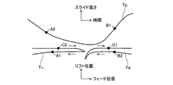
- FIG. 2 is a diagram for explaining the interference region.
- FIG. 2 shows an operation trajectory Tp of the press machine 10 (slide 11), an operation trajectory Tu of the upstream transport device, and an operation trajectory Td of the downstream transport device.
- the motion trajectory Tp is a trajectory when the horizontal axis is time and the vertical axis is the slide height, and the motion trajectories Tu and Td are the feed position (horizontal position) on the horizontal axis and the lift position (horizontal axis). This is the locus when the vertical position is assumed.
- the interference region A interference region between the upstream transport device and the press machine 10 in the first form and the interference region B in the second form.
- the position of the slide 11 (slide height) for each of the (interference area between the press machine 10 and the downstream conveyance apparatus) and the interference area C (interference area between the downstream conveyance apparatus and the upstream conveyance apparatus) in the third embodiment.
- parameters regarding the position of the conveying device 20 are set, and based on this parameter, it is determined whether or not the press machine 10 and the conveying device 20 are in the interference region.
- the operation control device determines that the upstream transfer device has come out of the interference area A, the position A1 where the slide 11 has entered the interference area A, and the slide 11 has come out of the interference area B.
- a position C2 at which it is determined that it has entered is set.
- the upstream-side transport controller 50 transmits to the press controller 40 the time until the upstream-side transport device passes the position A1 (time information indicating the timing of exiting from the interference area A). 11 is transmitted to the downstream side transport controller 50 until time 11 passes the position B1 (time information indicating the timing of exiting from the interference region B), and the downstream side transport controller 50 passes the position C1 of the downstream side transport device. The time until the transmission (time information indicating the timing of exiting from the interference area C) is transmitted to the upstream conveyance controller 50.
- time information indicating the timing of exiting from the interference area C is transmitted to the upstream conveyance controller 50.
- the time until exiting from the interference area is transmitted as time information.
- the time from the interference area may be transmitted as time information. In the latter case, the time obtained by adding the time until the exit from the interference area to the current time may be transmitted as time information.
- the “phase” for determining the operation section of the press machine 10 and the transport device 20 is managed.
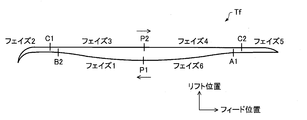
- FIG. 3 shows an operation trajectory Tf of the transport device 20.
- the position P1 is set near the midpoint when the transport device 20 moves upstream
- the position P2 is set near the midpoint when the transport device 20 moves downstream.
- the transport controller 50 sets the phase 1 when the transport device 20 is located in the section from the position P1 to the position B2, and sets the section from the position B2 to the position C1 (from entering the interference area B to exiting from the interference area C).
- Phase 2 when positioned in the section Phase 3 when positioned in the section from the position C1 to the position P2, and Phase 4 when positioned in the section from the position P2 to the position C2.
- Phase 5 when positioned in the section from A1 to position A1 (section from entering interference area C and exiting from interference area A), and Phase 6 when positioned in the section from position A1 to position P1
- the phase of the transport device 20 is managed. That is, here, as the phase of the conveying device 20, six operation sections are set by dividing the operation of the conveying device 20 into six.
- the transport controller 50 is set with a parameter VB that defines the transport speed of the transport device 20 in phase 2, and a parameter VC that defines the transport speed of the transport device 20 in phase 5.
- the transport controller 50 controls the transport device 20 to move at the speed (defined) specified by the parameter VB.
- control is performed so that the transport device 20 moves at a speed specified by the parameter VC.
- the transport controller 50 transports after the time when the slide of the upstream press machine exits the interference area B (time to pass the position B1).
- the device 20 is controlled so as to pass through the position B2 at the speed specified by the parameter VB.
- the transport controller 50 performs the transport device 20 after the time when the downstream transport device leaves the interference region C (time to pass the position C1). Is controlled to pass through the position C2 at the speed specified by the parameter VC. By doing so, it is possible to prevent interference between the downstream transport device being retracted and the transport device 20 entering (interference of the third embodiment).
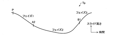
- FIG. 4 shows an operation locus Tp of the press machine 10.
- the position P is set near the top dead center.
- the press controller 40 sets the phase 1 when the slide 11 is located in the section from the position P to the position A2, and the section from the position A2 to the position B1 (the section from entering the interference area A to exiting the interference area B).
- the phase of the press machine 10 is managed as phase 2 when it is positioned at), and as phase 3 when it is positioned in the section from position B1 to position P. That is, here, as the operation section of the press machine 10, three operation sections obtained by dividing the operation of the slide 11 into three are set.
- the press controller 40 is set with a parameter VA that defines the speed of the slide 11 in the phase 2.
- the press controller 40 controls the slide 11 to move at the speed specified by the parameter VA.
- the press controller 40 has a time after the time when the upstream transfer device leaves the interference area A (time to pass through the position A1), Control is performed so that the slide 11 passes through the position A2 at a speed specified by the parameter VA. In this way, it is possible to prevent interference between the retreating upstream conveyance device and the slide 11 that is descending (interference of the first form).
- FIG. 5 is a functional block diagram showing the configuration of the transport controller 50.
- the transport controller 50 includes a state monitoring unit 51, a time calculation unit 52, a communication control unit 53, and a command generation unit 54.
- the state monitoring unit 51 detects in which section of the section (phase) shown in FIG. 3 the transport apparatus 20 is located, and updates the phase variable (section information indicating the operation section in which the transport apparatus 20 is located).
- the updated phase variable is output to the communication control unit 53 and the command generation unit 54.
- the phase variable is 1 to 6, it indicates that the phase of the transfer device 20 during the interlocking operation is 1 to 6, and when the phase variable is 0, it indicates that the transfer device 20 is not in the interlocking operation state. .
- the time calculation unit 52 calculates a time TA (time from the current time until the transport device 20 passes through the position A1) until the transport device 20 exits the interference area A, and the transport device 20 exits the interference area C.
- Time TC time from the current time until the transport device 20 passes the position C1 is calculated.
- the calculated time TA and time TC are continuously output while decreasing with the elapsed time. Note that the lower limit values of the time TA and the time TC are set to 0.1 seconds, for example, and 0 seconds are output when the values cannot be calculated.
- the communication control unit 53 performs control to transmit the phase variable output from the state monitoring unit 51 to the upstream press controller 40 and the downstream press controller 40. Further, the communication control unit 53 transmits the time TA output from the time calculation unit 52 to the downstream press controller 40 and transmits the time TC output from the time calculation unit 52 to the upstream transport controller 50. For example, the communication control unit 53 of the transport controller 50B transmits the time TA to the press controller 40B and transmits the time TC to the transport controller 50A.
- the communication control unit 53 receives a time TB until the upstream press machine (slide) exits from the interference area B from the upstream press controller 40, and a time TC until the downstream transport device exits from the interference area C. Is received from the transport controller 50 on the downstream side.
- the communication control unit 53 of the transport controller 50B receives the time TB from the press controller 40A and receives the time TC from the transport controller 50C.
- the communication control unit 53 receives an interference area state variable described later from each of the upstream and downstream press controllers 40.
- the state monitoring unit 51 monitors the abnormality of the transfer device 20 and sets an abnormal state variable to 1 (own device error) when a failure of the drive unit of the transfer device 20 is detected. Further, the state monitoring unit 51 monitors the time TB received from the upstream press controller 40 and the time TC received from the downstream transport controller 50, and if there is an abnormality in the received time TB, If the state variable is 2 (upstream device abnormality) and the received time TC is abnormal, the abnormal state variable is 3 (downstream device abnormality).
- the command generation unit 54 controls the operation of the conveyance device 20 (conveyance body 22) by calculating an operation command value to a servo motor that drives the conveyance body 22 of the conveyance device 20 and outputting the operation command value to the conveyance device 20. Based on the phase variable output from the state monitoring unit 51, the time TB, the time TC, and the interference region state variable received by the communication control unit 53, the command generating unit 54 determines that the upstream press machine (slide) is in the interference region. After the time exiting from B (timing exiting from interference area B or timing after exiting from interference area B), it passes through position B2 at the speed specified by parameter VB, and phase 2 at the speed specified by parameter VB.
- control is performed so as to move through the section of phase 5 at the speed specified by the parameter VC through the position C2. Further, the command generation unit 54 issues a stop command when the abnormal state variable output from the state monitoring unit 51 is a value other than zero.
- FIG. 6 is a functional block diagram showing the configuration of the press controller 40.
- the press controller 40 includes a state monitoring unit 41, a time calculation unit 42, a communication control unit 43, and a command generation unit 44.
- the state monitoring unit 41 detects in which section of the section (phase) shown in FIG. 4 the slide 11 is located, and updates the phase variable (section information indicating the operation section in which the slide 11 is located).
- the updated phase variable is output to the command generation unit 44.
- the phase variable is 1 to 3 it indicates that the phase of the press machine 10 during the interlocking operation is 1 to 3, and when the phase variable is 0, it indicates that the press machine 10 is not in the interlocking operation state. .
- the time calculation unit 42 calculates a time TB (a time from the present time until the slide 11 passes through the position B1) until the slide 11 comes out of the interference area B.
- the calculated time TB is continuously output while decreasing with the elapsed time.
- the lower limit of the time TB is set to 0.1 seconds, for example, and 0 seconds is output when the value cannot be calculated.
- the communication control unit 43 performs control to transmit the time TB output from the time calculation unit 42 to the transport controller 50 on the downstream side.
- the communication control unit 43 of the press controller 40A transmits the time TB to the transport controller 50B.
- the communication control unit 43 receives the time TA from the upstream side transport controller 50 until the upstream side transport device leaves the interference area A.
- the communication control unit 43 of the press controller 40A receives the time TA from the transport controller 50A.
- the communication control unit 43 receives the phase variable (upstream device phase variable) transmitted from the upstream transport controller 50 and the phase variable (downstream device phase variable) transmitted from the downstream transport controller 50.
- the state monitoring unit 41 monitors the phase variable of the press machine 10 (own device), the upstream device phase variable and the downstream device phase variable received by the communication control unit 43, and determines the interference region state variable (the state of the interference region). Update status information). Specifically, when the upstream device phase variable is changed from 4 to 5, the state monitoring unit 41 sets the interference region state variable to 2 (while the upstream transfer device is entering), and the upstream device phase variable is changed from 5 to 6. When changed, the interference region state variable is set to 3 (with unprocessed workpiece), and when the phase variable of the own device is changed from 1 to 2, the interference region state variable is set to 4 (during press molding).
- the interference region state variable is 5 (with processed workpiece), and when the downstream device phase variable is changed from 1 to 2, the interference region state variable is 6 (downstream transfer)
- the interference region state variable is set to 1 (no workpiece).
- the interference area state variable is set to 0.
- the communication control unit 43 transmits the interference region state variable output from the state monitoring unit 41 to each of the upstream side transport controller 50 and the downstream side transport controller 50.
- the state monitoring unit 41 monitors the abnormality of the press machine 10 and sets an abnormal state variable to 1 (own device abnormality) when a failure of the drive unit of the press machine 10 is detected. In addition, the state monitoring unit 41 monitors the time TA received from the upstream side transport controller 50, and sets the abnormal state variable to 2 (upstream device abnormality) if the received time TA is abnormal. The determination of whether or not the received time TA is abnormal is the same as the determination of the time TB and the time TC in the transport controller 50. When the abnormal state variable is 0, no abnormality is assumed.
- the command generation unit 44 controls the operation of the press machine 10 (slide 11) by calculating an operation command value to the servo motor that drives the slide 11 of the press machine 10 and outputting it to the press machine 10. Based on the interference region state variable output from the state monitoring unit 41 and the time TA received by the communication control unit 43, the command generation unit 44 performs the time after the time when the upstream transport device leaves the interference region A (interference region A Control to move through the phase 2 at a speed determined by the parameter VA at a speed determined by the parameter VA at a time determined by the parameter VA. To do. Further, the command generation unit 44 issues a stop command when the abnormal state variable output from the state monitoring unit 41 is a value other than zero.
- the transport controller 50 determines whether or not the transport device 20 holds a workpiece (step S10). For example, whether or not a workpiece is held is determined based on a state acquired by a sensor or a value visually input by an operator.
- the command generation unit 54 performs control to move the transport device 20 to the vicinity of the position P1 (Step S12), and proceeds to Step S32.
- the vicinity of the position P1 is specified by the parameter VB until it can move without interfering with the upstream press machine and the downstream press machine even when the transport device 20 is in that position and moves to the position B2. It is a position that can take a sufficient distance to accelerate to a certain speed.
- Step S14 the command generation unit 54 performs control to move the transport device 20 to the vicinity of the position P2 (Step S14), and proceeds to Step S16.
- the vicinity of the position P2 can be operated without interfering with the upstream side press machine and the downstream side press machine even when the transport device 20 is in that position, and is designated by the parameter VC before moving to the position C2. It is a position that can take a sufficient distance to accelerate to a certain speed.
- the interference region state variable received from the downstream press controller 40 is 1 (the state information indicates that there is no workpiece, that is, there is no workpiece in the downstream press machine, and the downstream conveyance device interferes) It is determined whether it is not in area C (step S16).
- the command generation unit 54 controls the transport device 20 to pass the position C2 at the speed specified by the parameter VC in the shortest time. (Step S18), the process proceeds to Step S28.
- the downstream apparatus interference area exit time time TC until the downstream conveyor apparatus exits from the interference area C received from the downstream transport controller 50 is 0. It is determined whether it is 1 second or longer (step S20). If the downstream device interference area exit time is 0.1 second or longer (Y in step S20), the command generation unit 54 determines that the parameter after the time when the transport device 20 exits the interference region C from the downstream transport device Control is performed so as to pass the position C2 at a speed designated by VC (step S22), and the process proceeds to step S28.
- step S24 If the downstream device interference area exit time is not 0.1 second or longer (N in step S20), it is determined whether or not a stop command is issued (step S24), and if a stop command is issued (step S24). In Y), an end process is started.
- the command generation unit 54 moves the transport device 20 to the vicinity of the position P2 and waits (if the transport device 20 is stopped near the position P2, the standby is performed as it is. ) (Step S26), and the process proceeds to step S16.
- step S28 it is determined whether or not the phase variable (phase variable of the own device) output from the state monitoring unit 51 has changed from 5 to 6 (step S28), and the phase variable has not changed from 5 to 6 In (N of step S28), it is determined whether or not a stop command has been issued (step S30). If a stop command has been issued (Y in step S30), an end process is started. If no stop command has been issued (N in step S30), the process proceeds to step S28.
- the interference area state variable received from the upstream press controller 40 is 5 (the state information indicates that there is a workpiece after processing). That is, it is determined whether or not there is a processed workpiece in the upstream press machine and the slide 11 is not in the interference region B) (step S32).
- the command generation unit 54 controls the transport device 20 to pass the position B2 at the speed specified by the parameter VB in the shortest time. (Step S34), the process proceeds to Step S44.
- the upstream apparatus interference area exit time time TB until the upstream press machine exits from the interference area B received from the upstream press controller 40 is 0. It is determined whether it is 1 second or longer (step S36). When the upstream device interference area exit time is 0.1 second or longer (Y in step S36), the command generation unit 54 sets the parameter after the time when the transport device 20 leaves the interference area B from the upstream press machine. Control is performed so as to pass through the position B2 at a speed designated by VB (step S38), and the process proceeds to step S44.
- Step S40 If the upstream device interference area exit time is not 0.1 second or longer (N in Step S36), it is determined whether or not a stop command is issued (Step S40), and if a stop command is issued (Step S40). In Y), an end process is started.
- the command generation unit 54 moves the transport device 20 to near the position P1 and waits (if the transport device 20 is stopped near the position P1, it stands by as it is). ) (Step S42), and the process proceeds to step S32.
- step S44 it is determined whether or not the phase variable of the own device has changed from 2 to 3 (step S44). If the phase variable of the own device has changed from 2 to 3 (Y in step S44), step S16 is performed. Migrate to If the phase variable has not changed from 2 to 3 (N in Step S44), it is determined whether or not a stop command has been issued (Step S46), and if a stop command has been issued (Y in Step S46). In this case, the end process is started. If no stop command has been issued (N in step S46), the process proceeds to step S44.
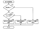
- FIG. 9 is a flowchart showing the flow of the linked operation end process of the transport device 20.
- the transport controller 50 determines whether or not the type of stop command is an emergency stop (step S48). If the stop command is an emergency stop (Y in step S48), the phase variable of the own device is 2 or 5; (That is, in the interference region) (step S50).
- step S50 When the phase variable is 2 or 5 (Y in step S50), the command generation unit 54 performs control to decelerate the transport device 20 with a moderate deceleration (step S52). On the other hand, when the phase variable is not 2 or 5 (any one of 3, 4, 6, 1) (N in Step S50), the command generation unit 54 decelerates the transport device 20 with a rapid deceleration. Control is performed (step S54).
- the transport device 20 when the transport device 20 is in the interference region, the transport device 20 is decelerated at a slow deceleration so as to exit the interference region, and when the transport device 20 is not in the interference region, the transport device 20 By decelerating at a rapid deceleration so that the device 20 does not approach the interference area, it is possible to prevent interference between the devices even when communication between the controllers becomes impossible. If it is not an emergency stop (N in Step S48), the command generation unit 54 performs control to move the transport device 20 to the position P1 or near P2 and stop it (Step S56).
- FIG. 10 is a flowchart showing a flow of processing for outputting the interference area departure time of the transport device 20.
- the transport controller 50 determines whether or not a process of waiting or stopping the transport apparatus 20 is being executed (step S58). If the process is being executed (Y in step S58), the time The calculation unit 52 includes a time TC (time information indicating timing to exit from the interference region C) until the transport device 20 passes the position C1, and a time TA (out of the interference region A) until the transport device 20 passes the position A1. 0 is output as both (time information indicating timing) (step S60). The time TC is transmitted to the upstream transport controller 50, and the time TA is transmitted to the downstream press controller 40. Next, it is determined whether or not to end the operation (step S62). When the operation is continued (N in step S62), the process proceeds to step S58.
- Step S64 it is determined whether the phase variable of the own device is 6 or 1 or 2 (Step S64).
- the time calculation unit 52 calculates and outputs the time TC until the transport device 20 passes the position C1 (Step S66).
- the conveying device 20 passes through the position B2 after the time when the upstream press machine leaves the interference area B, and moves in phase 2 (section from the position B2 to the position C1) at the speed specified by the parameter VB. Therefore, the time TC can be calculated from the upstream device interference area departure time received from the upstream press controller 40, the parameter VB, and the current position of the transport device 20.
- step S68 it is determined whether or not the downstream device interference area departure time received from the downstream transport controller 50 is 0 (step S68). If it is 0 (Y in step S68), the time calculation unit 52 is determined. Outputs 0 as time TA (step S70). If the downstream device interference area departure time is not 0 (N in step S68), the time calculation unit 52 calculates and outputs the time TA until the transport device 20 passes through the position A1 (step S72). Here, the transport device 20 passes through the position C2 after the time when the downstream transport device leaves the interference area C, and moves in phase 5 (section from the position C2 to the position A1) at the speed specified by the parameter VC. Therefore, the time TA can be calculated from the downstream device interference region departure time received from the downstream transport controller 50, the parameter VC, and the current position of the transport device 20.
- the time calculation unit 52 calculates and outputs the time TA until the transport device 20 passes through the position A1 (Step S74).
- FIG. 11 is a flowchart showing the flow of the linked operation process of the press machine 10.
- the press machine 10 starts the linked operation from the vicinity of the top dead center.
- the vicinity of the top dead center is a slide height that is higher than the position B1 and that can be penetrated by both the upstream side transport device and the downstream side transport device, and is determined by the parameter VA before moving to the position A2.
- the interference region state variable output from the state monitoring unit 41 is 3 (the state information indicates that there is a workpiece before processing, that is, there is an unprocessed workpiece, and upstream conveyance It is determined whether or not the device is not in the interference area A (step S82).
- the interference area state variable is 3 (Y in step S82)
- the command generator 44 controls the press machine 10 to pass the position A2 at the speed specified by the parameter VA in the shortest time. (Step S84), the process proceeds to Step S94.
- the upstream apparatus interference area departure time time TA until the upstream conveyance apparatus leaves the interference area A received from the upstream conveyance controller 50 is 0. It is determined whether it is 1 second or longer (step S86). When the upstream device interference area exit time is 0.1 second or longer (Y in step S86), the command generation unit 44 sets the parameter after the time when the press machine 10 leaves the interference area A from the upstream transport device. Control is performed so as to pass the position A2 at a speed designated by VA (step S88), and the process proceeds to step S94.
- Step S90 If the upstream device interference area departure time is not 0.1 second or longer (N in Step S86), it is determined whether or not a stop command has been issued (Step S90), and if a stop command has been issued (Step S90). In Y), an end process is started.
- the command generation unit 44 moves the press machine 10 to near the position P (near top dead center) and waits (the press machine 10 stops near the position P). If it is in the middle, control is performed so that it stands by (step S92), and the process proceeds to step S82.
- step S94 it is determined whether or not the phase variable of the own device has changed from 2 to 3 (step S94). If the phase variable of the own device has changed from 2 to 3 (Y in step S94), step S82 is performed. Migrate to If the phase variable has not changed from 2 to 3 (N in step S94), it is determined whether or not a stop command has been issued (step S96), and if a stop command has been issued (Y in step S96). In this case, the end process is started. If no stop command has been issued (N in step S96), the process proceeds to step S94.
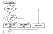
- FIG. 12 is a flowchart showing the flow of the linked operation end process of the press machine 10.
- the press controller 40 determines whether or not the type of stop command is an emergency stop (step S98). If it is an emergency stop (Y in step S98), the phase variable of its own device is 2 or 3. It is judged whether it is (step S100).
- step S100 When the phase variable is 2 or 3 (Y in step S100), the command generation unit 44 performs control to decelerate the slide 11 with a moderate deceleration (step S102). On the other hand, when the phase variable is not 2 or 3 (1) (N in Step S100), the command generation unit 44 performs control to decelerate the slide 11 with a rapid deceleration (Step S104).
- the slide 11 when the slide 11 is in the interference area, the slide 11 is decelerated at a slow deceleration so as to exit the interference area, and when the slide 11 is in front of the interference area, the slide 11 By decelerating at a rapid deceleration so that 11 does not approach the interference region, it is possible to prevent interference between devices even when communication between controllers becomes impossible. If it is not an emergency stop (N in Step S98), the command generation unit 44 performs control to move the slide 11 to the vicinity of the position P and stop it (Step S106).
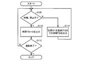
- FIG. 13 is a flowchart showing a flow of processing for outputting the interference area departure time of the press machine 10.
- the press controller 40 determines whether or not a process of waiting or stopping the press machine 10 is being executed (step S108). If the process is being executed (Y in step S108), the time The calculation unit 42 outputs 0 as the time TB (time information indicating the timing of exiting from the interference region B) until the slide 11 passes through the position B1 (step S110). The time TB is transmitted to the downstream transport controller 50. Next, it is determined whether or not to end the operation (step S112). When the operation is continued (N in step S112), the process proceeds to step S108.
- the time calculation unit 42 calculates and outputs the time TB until the slide 11 passes through the position B1 (Step S114).
- the slide 11 passes through the position A2 after the time when the upstream transport device leaves the interference area A and moves in phase 2 (section from the position A2 to the position B1) at the speed specified by the parameter VA.
- the upstream device interference area exit time time TA until the upstream side transport device leaves the interference area A received from the upstream transport controller 50, the parameter VA, and the time TB from the current position of the slide 11 are controlled. Can be calculated.
- FIG. 14 shows an example of transition of variables (time TA, time TB, time TC, phase variable) generated by the upstream side transfer controller, the press controller, and the downstream side transfer controller.
- the press machine enters the interference area A at the time T 1 (the timing at which the upstream transfer apparatus phase variable changes to 6) (the phase variable of the press machine changes). 2), at the time T 2 when the press machine leaves the interference region B (timing when the phase variable of the press machine changes to 3), the downstream side transport device enters the interference region B (the phase variable of the downstream side transport device becomes 2). changes), the downstream transport device at the timing phase variable changes the third time T 3 (downstream transport device leaving the interference area C) upstream transport device enters the interference region C (phase variables of the upstream-side transport device As shown in FIG. 5, each device is operating in conjunction.
- the press controller 40 acquires time information indicating the timing at which the upstream conveyance device exits the interference area A from the upstream conveyance controller 50, and the upstream conveyance apparatus moves from the interference area A.
- the slide 11 is controlled to enter the interference area A
- the downstream transport controller 50 acquires time information indicating the timing at which the slide 11 exits the interference area B from the press controller 40. Control is performed so that the downstream transport device enters the interference region B after the time (time) when the slide 11 exits the interference region B, and the upstream transport controller 50 indicates the timing at which the downstream transport device exits the interference region C.
- the time information is acquired from the downstream transport controller 50, and the time is increased after the time (time) when the downstream transport device leaves the interference area C.
- each device upstream transfer device and press machine, press machine and downstream transfer device, downstream transfer device and upstream transfer device. Interlocked operation is possible.
- each controller generates an operation command value regardless of other devices or an external master signal. Therefore, the influence of communication jitter and CPU clock differences affects the operation of each device. It is possible to prevent reaching the command value. Further, the linked operation can be performed even when the communication speed between the controllers is slow or varies. In this case, the communication delay between the controllers can be measured in advance, and correction can be performed by subtracting it from the interference zone departure time acquired from another controller using the value.
Landscapes
- Engineering & Computer Science (AREA)
- Mechanical Engineering (AREA)
- Press Drives And Press Lines (AREA)
Abstract
Description
前記第2搬送コントローラと前記第2プレスコントローラは、互いに通信可能に接続されていてもよい。
Claims (10)
- 第1プレス機械と、前記第1プレス機械に加工前のワークを搬入する第1搬送装置と、前記第1プレス機械から加工後のワークを搬出する第2搬送装置とを含むプレスラインの運転制御装置であって、
前記第1プレス機械を制御する第1プレスコントローラと、
前記第1搬送装置を制御する第1搬送コントローラと、
前記第2搬送装置を制御する第2搬送コントローラとを含み、
前記第1プレスコントローラ、前記第1搬送コントローラ及び前記第2搬送コントローラは、互いに通信可能に接続され、
前記第1搬送コントローラは、
前記第1搬送装置が前記第1プレス機械との干渉領域から出るタイミングを示す時間情報を前記第1プレスコントローラに送信し、
前記第1プレスコントローラは、
前記第1搬送コントローラから受信した前記時間情報に基づいて、前記第1搬送装置が前記干渉領域から出る時間以降に前記第1プレス機械のスライドが前記第1搬送装置との干渉領域に入るように前記第1プレス機械を制御し、前記第1プレス機械のスライドが前記第2搬送装置との干渉領域から出るタイミングを示す時間情報を前記第2搬送コントローラに送信し、
前記第2搬送コントローラは、
前記第1プレスコントローラから受信した前記時間情報に基づいて、前記第1プレス機械のスライドが前記干渉領域から出る時間以降に前記第2搬送装置が前記第1プレス機械との干渉領域に入るように前記第2搬送装置を制御する、プレスラインの運転制御装置。 - 請求項1において、
前記第2搬送コントローラは、
前記第2搬送装置が前記第1搬送装置との干渉領域から出るタイミングを示す時間情報を前記第1搬送コントローラに送信し、
前記第1搬送コントローラは、
前記第2搬送コントローラから受信した前記時間情報に基づいて、前記第2搬送装置が前記干渉領域から出る時間以降に前記第1搬送装置が前記第2搬送装置との干渉領域に入るように前記第1搬送装置を制御する、プレスラインの運転制御装置。 - 請求項2において、
前記第1プレスコントローラは、
前記第1プレス機械のスライドが予め指定された速度で前記第1搬送装置との干渉領域に入るように前記第1プレス機械を制御し、
前記第2搬送コントローラは、
前記第2搬送装置が予め指定された速度で前記第1プレス機械との干渉領域に入るように前記第2搬送装置を制御し、
前記第1搬送コントローラは、
前記第1搬送装置が予め指定された速度で前記第2搬送装置との干渉領域に入るように前記第1搬送装置を制御する、プレスラインの運転制御装置。 - 請求項1において、 前記プレスラインは、第2プレス機械と、前記第2プレス機械を制御する第2プレスコントローラを更に含み、前記第2搬送装置は、前記第1プレス機械から搬出したワークを前記第2プレス機械に搬入し、
前記第2搬送コントローラと前記第2プレスコントローラは、互いに通信可能に接続されている、プレスラインの運転制御装置。 - 請求項4において、
前記第2搬送コントローラは、
前記第2搬送装置が前記第2プレス機械との干渉領域から出るタイミングを示す時間情報を前記第2プレスコントローラに送信し、
前記第2プレスコントローラは、
前記第2搬送コントローラから受信した前記時間情報に基づいて、前記第2搬送装置が前記干渉領域から出る時間以降に前記第2プレス機械のスライドが前記第2搬送装置との干渉領域に入るように前記第2プレス機械を制御する、プレスラインの運転制御装置。 - 請求項5において、
前記第2プレスコントローラは、
前記第2プレス機械のスライドが予め指定された速度で前記第2搬送装置との干渉領域に入るように前記第2プレス機械を制御する、プレスラインの運転制御装置。 - 請求項2において、
前記第1搬送コントローラは、
前記第1搬送装置の動作を分割した複数の動作区間のうち前記第1搬送装置が位置する動作区間を示す区間情報を更新し、更新した前記区間情報を前記第1プレスコントローラに送信し、
前記第2搬送コントローラは、
前記第2搬送装置の動作を分割した複数の動作区間のうち前記第2搬送装置が位置する動作区間を示す区間情報を更新し、更新した前記区間情報を前記第1プレスコントローラに送信し、
前記第1プレスコントローラは、
前記第1プレス機械のスライドの動作を分割した複数の動作区間のうち前記第1プレス機械のスライドが位置する動作区間を示す区間情報を更新し、更新した前記区間情報と、前記第1搬送コントローラ及び前記第2搬送コントローラから受信した前記区間情報とに基づいて、前記干渉領域の状態を示す状態情報を更新し、更新した前記状態情報を前記第1搬送コントローラ及び前記第2搬送コントローラに送信し、
前記状態情報が、加工前のワークがあることを示す場合には、前記第1プレス機械のスライドが最短時間で前記第1搬送装置との干渉領域に入るように前記第1プレス機械を制御し、当該状態情報が、加工前のワークがあることを示す場合以外の場合には、前記第1搬送コントローラから受信した前記時間情報に基づいて、前記第1搬送装置が前記干渉領域から出る時間以降に前記第1プレス機械のスライドが前記第1搬送装置との干渉領域に入るように前記第1プレス機械を制御し、
前記第2搬送コントローラは、
前記第1プレスコントローラから受信した前記状態情報が、加工後のワークがあることを示す場合には、前記第2搬送装置が最短時間で前記第1プレス機械との干渉領域に入るように前記第2搬送装置を制御し、当該状態情報が、加工後のワークがあることを示す場合以外の場合には、前記第1プレスコントローラから受信した前記時間情報に基づいて、前記第1プレス機械のスライドが前記干渉領域から出る時間以降に前記第2搬送装置が前記第1プレス機械との干渉領域に入るように前記第2搬送装置を制御し、
前記第1搬送コントローラは、
前記第1プレスコントローラから受信した前記状態情報が、ワークがないことを示す場合には、前記第1搬送装置が最短時間で前記第2搬送装置との干渉領域に入るように前記第1搬送装置を制御し、当該状態情報が、ワークがないことを示す場合以外の場合には、前記第2搬送コントローラから受信した前記時間情報に基づいて、前記第2搬送装置が前記干渉領域から出る時間以降に前記第1搬送装置が前記第2搬送装置との干渉領域に入るように前記第1搬送装置を制御する、プレスラインの運転制御装置。 - 請求項2において、
前記第1プレスコントローラは、
前記第1プレス機械の異常を監視し、前記第1搬送コントローラから受信した前記時間情報を監視することで前記第1搬送装置の異常を監視し、
前記第2搬送コントローラは、
前記第2搬送装置の異常を監視し、前記第1プレスコントローラから受信した前記時間情報を監視することで前記第1プレス機械の異常を監視し、
前記第1搬送コントローラは、
前記第1搬送装置の異常を監視し、前記第2搬送コントローラから受信した前記時間情報を監視することで前記第2搬送装置の異常を監視する、プレスラインの運転制御装置。 - 第1プレス機械と、前記第1プレス機械に加工前のワークを搬入する第1搬送装置と、前記第1プレス機械から加工後のワークを搬出する第2搬送装置と、前記第1プレス機械を制御する第1プレスコントローラと、前記第1搬送装置を制御する第1搬送コントローラと、前記第2搬送装置を制御する第2搬送コントローラとを含むプレスラインの運転制御方法であって、
前記第1搬送コントローラが、前記第1搬送装置が前記第1プレス機械との干渉領域から出るタイミングを示す時間情報を前記第1プレスコントローラに送信するステップと、
前記第1プレスコントローラが、前記第1搬送コントローラから受信した前記時間情報に基づいて、前記第1搬送装置が前記干渉領域から出る時間以降に前記第1プレス機械のスライドが前記第1搬送装置との干渉領域に入るように前記第1プレス機械を制御し、前記第1プレス機械のスライドが前記第2搬送装置との干渉領域から出るタイミングを示す時間情報を前記第2搬送コントローラに送信するステップと、
前記第2搬送コントローラが、前記第1プレスコントローラから受信した前記時間情報に基づいて、前記第1プレス機械のスライドが前記干渉領域から出る時間以降に前記第2搬送装置が前記第1プレス機械との干渉領域に入るように前記第2搬送装置を制御するステップとを含む、プレスラインの運転制御方法。 - 請求項9において、
前記プレスラインは、第2プレス機械と、前記第2プレス機械を制御する第2プレスコントローラを更に含み、前記第2搬送装置は、前記第1プレス機械から搬出したワークを前記第2プレス機械に搬入し、
前記第2搬送コントローラが、前記第2搬送装置が前記第2プレス機械との干渉領域から出るタイミングを示す時間情報を前記第2プレスコントローラに送信するステップと、
前記第2プレスコントローラが、前記第2搬送コントローラから受信した前記時間情報に基づいて、前記第2搬送装置が前記干渉領域から出る時間以降に前記第2プレス機械のスライドが前記第2搬送装置との干渉領域に入るように前記第2プレス機械を制御するステップとを含む、プレスラインの運転制御方法。
Priority Applications (4)
| Application Number | Priority Date | Filing Date | Title |
|---|---|---|---|
| EP16851340.6A EP3357678A4 (en) | 2015-09-28 | 2016-09-23 | Operation control device and operation control method for press line |
| CN201680055743.6A CN108136705A (zh) | 2015-09-28 | 2016-09-23 | 冲压生产线的运转控制装置和运转控制方法 |
| US15/761,941 US20180290198A1 (en) | 2015-09-28 | 2016-09-23 | Operation control device and operation control method for press line |
| JP2017501341A JP6249583B2 (ja) | 2015-09-28 | 2016-09-23 | プレスラインの運転制御装置及び運転制御方法 |
Applications Claiming Priority (2)
| Application Number | Priority Date | Filing Date | Title |
|---|---|---|---|
| JP2015189193 | 2015-09-28 | ||
| JP2015-189193 | 2015-09-28 |
Publications (1)
| Publication Number | Publication Date |
|---|---|
| WO2017057166A1 true WO2017057166A1 (ja) | 2017-04-06 |
Family
ID=58424110
Family Applications (1)
| Application Number | Title | Priority Date | Filing Date |
|---|---|---|---|
| PCT/JP2016/077960 WO2017057166A1 (ja) | 2015-09-28 | 2016-09-23 | プレスラインの運転制御装置及び運転制御方法 |
Country Status (5)
| Country | Link |
|---|---|
| US (1) | US20180290198A1 (ja) |
| EP (1) | EP3357678A4 (ja) |
| JP (1) | JP6249583B2 (ja) |
| CN (1) | CN108136705A (ja) |
| WO (1) | WO2017057166A1 (ja) |
Families Citing this family (2)
| Publication number | Priority date | Publication date | Assignee | Title |
|---|---|---|---|---|
| CN111376516A (zh) * | 2018-12-28 | 2020-07-07 | 上海新时达机器人有限公司 | 一种冲压装置控制系统及方法 |
| JP7316111B2 (ja) * | 2019-06-25 | 2023-07-27 | ファナック株式会社 | プレス加工シミュレーション装置 |
Citations (4)
| Publication number | Priority date | Publication date | Assignee | Title |
|---|---|---|---|---|
| JP2004216429A (ja) * | 2003-01-16 | 2004-08-05 | Komatsu Ltd | タンデムプレスラインの異常処理システム |
| JP2010075936A (ja) * | 2008-09-24 | 2010-04-08 | Honda Motor Co Ltd | プレスラインの運転条件設定方法 |
| JP2012066254A (ja) * | 2010-09-21 | 2012-04-05 | Hitachi Zosen Fukui Corp | タンデムプレスラインの制御方法 |
| JP2015006690A (ja) * | 2013-05-30 | 2015-01-15 | アイダエンジニアリング株式会社 | サーボプレスラインの運転方法および運転制御装置 |
Family Cites Families (13)
| Publication number | Priority date | Publication date | Assignee | Title |
|---|---|---|---|---|
| CN1471032A (zh) * | 2002-07-25 | 2004-01-28 | 杨文镛 | 一种整合生产线的监视方法及装置 |
| CN100340390C (zh) * | 2003-05-01 | 2007-10-03 | 株式会社小松制作所 | 串行式连续冲压生产线、串行式连续冲压生产线的运转控制方法及串行式连续冲压生产线的工件运送装置 |
| JP4270497B2 (ja) * | 2003-06-24 | 2009-06-03 | アイダエンジニアリング株式会社 | プレス機械 |
| JP4507250B2 (ja) * | 2004-10-29 | 2010-07-21 | アイダエンジニアリング株式会社 | トランスファプレス機械 |
| JP4382003B2 (ja) * | 2005-03-23 | 2009-12-09 | 川崎重工業株式会社 | ロボット制御装置およびロボット制御方法 |
| ES2452022T3 (es) * | 2006-02-06 | 2014-03-31 | Abb Research Ltd. | Sistema de línea de prensas y método |
| JP4859734B2 (ja) * | 2007-04-09 | 2012-01-25 | アイダエンジニアリング株式会社 | プレスラインのモーション位相調整方法及び装置 |
| JP5234320B2 (ja) * | 2008-01-28 | 2013-07-10 | 株式会社Ihi | サーボプレスラインとその制御方法 |
| JP2009285666A (ja) * | 2008-05-27 | 2009-12-10 | Ihi Corp | サーボプレス設備とその制御方法 |
| JP4702901B2 (ja) * | 2008-07-07 | 2011-06-15 | アイダエンジニアリング株式会社 | サーボプレスラインの運転方法および運転制御装置 |
| JP5647059B2 (ja) * | 2011-04-27 | 2014-12-24 | アイダエンジニアリング株式会社 | タンデムプレスライン |
| JP5768829B2 (ja) * | 2013-03-15 | 2015-08-26 | 株式会社安川電機 | ロボットシステム、ロボット制御方法及び被加工物の製造方法 |
| CN104525665B (zh) * | 2014-12-31 | 2017-03-15 | 广州市金峰机械科技有限公司 | 一种自动冲压方法及其生产线 |
-
2016
- 2016-09-23 EP EP16851340.6A patent/EP3357678A4/en not_active Withdrawn
- 2016-09-23 CN CN201680055743.6A patent/CN108136705A/zh active Pending
- 2016-09-23 WO PCT/JP2016/077960 patent/WO2017057166A1/ja active Application Filing
- 2016-09-23 JP JP2017501341A patent/JP6249583B2/ja active Active
- 2016-09-23 US US15/761,941 patent/US20180290198A1/en not_active Abandoned
Patent Citations (4)
| Publication number | Priority date | Publication date | Assignee | Title |
|---|---|---|---|---|
| JP2004216429A (ja) * | 2003-01-16 | 2004-08-05 | Komatsu Ltd | タンデムプレスラインの異常処理システム |
| JP2010075936A (ja) * | 2008-09-24 | 2010-04-08 | Honda Motor Co Ltd | プレスラインの運転条件設定方法 |
| JP2012066254A (ja) * | 2010-09-21 | 2012-04-05 | Hitachi Zosen Fukui Corp | タンデムプレスラインの制御方法 |
| JP2015006690A (ja) * | 2013-05-30 | 2015-01-15 | アイダエンジニアリング株式会社 | サーボプレスラインの運転方法および運転制御装置 |
Non-Patent Citations (1)
| Title |
|---|
| See also references of EP3357678A4 * |
Also Published As
| Publication number | Publication date |
|---|---|
| JP6249583B2 (ja) | 2017-12-20 |
| EP3357678A4 (en) | 2018-10-31 |
| JPWO2017057166A1 (ja) | 2017-10-05 |
| CN108136705A (zh) | 2018-06-08 |
| US20180290198A1 (en) | 2018-10-11 |
| EP3357678A1 (en) | 2018-08-08 |
Similar Documents
| Publication | Publication Date | Title |
|---|---|---|
| EP2958834B1 (en) | Method and apparatus for changing carriage speed on a closed-loop track | |
| CN108349055B (zh) | 移动行进体的方法、直线驱动器和生产机器 | |
| US20180164788A1 (en) | Production system, controller, and control method | |
| JP5019250B2 (ja) | サーボプレス設備とその制御方法 | |
| JP5647059B2 (ja) | タンデムプレスライン | |
| KR102404513B1 (ko) | 물품 반송 설비 | |
| JP6295242B2 (ja) | 搬送台車、搬送台車の駆動制御方法、及び搬送台車の駆動制御プログラム | |
| JP5897648B2 (ja) | 同期制御中に位置制御のゲインを切換える機能を有する数値制御装置 | |
| US9233802B2 (en) | Conveyor device for the conveyance of workpieces, specifically of circuit boards, in the conveyance direction along a conveyance path | |
| US8096233B2 (en) | Servo press line operation method and servo press line operation control device | |
| JP6249583B2 (ja) | プレスラインの運転制御装置及び運転制御方法 | |
| JP5158467B2 (ja) | サーボプレス設備とその制御方法 | |
| WO2009093368A1 (ja) | 製造設備 | |
| JP5234320B2 (ja) | サーボプレスラインとその制御方法 | |
| JP5136847B2 (ja) | サーボプレス設備とその制御方法 | |
| KR102447060B1 (ko) | 부서지기 쉬운 물체를 운송하기 위한 운송 장치 및 운송 방법 | |
| TWI592775B (zh) | 機器設備端效器於生產作業系統的軌跡規劃與控制方法 | |
| KR20240112431A (ko) | 갠트리로더의 제어 방법 | |
| KR102289024B1 (ko) | 이송 장치 | |
| JP5054779B2 (ja) | トランスファプレス装置 | |
| KR101262831B1 (ko) | 프레스 라인용 연속운전 시스템 | |
| WO2022118704A1 (ja) | 生産システム | |
| US11565410B2 (en) | Robot task system | |
| JP2002019948A (ja) | 搬送装置用制御装置 | |
| JP2013071234A (ja) | ロボットの停止方法およびロボットシステム |
Legal Events
| Date | Code | Title | Description |
|---|---|---|---|
| ENP | Entry into the national phase |
Ref document number: 2017501341 Country of ref document: JP Kind code of ref document: A |
|
| 121 | Ep: the epo has been informed by wipo that ep was designated in this application |
Ref document number: 16851340 Country of ref document: EP Kind code of ref document: A1 |
|
| WWE | Wipo information: entry into national phase |
Ref document number: 15761941 Country of ref document: US |
|
| NENP | Non-entry into the national phase |
Ref country code: DE |
|
| WWE | Wipo information: entry into national phase |
Ref document number: 2016851340 Country of ref document: EP |