WO2017056795A1 - クリーニングブレード - Google Patents
クリーニングブレード Download PDFInfo
- Publication number
- WO2017056795A1 WO2017056795A1 PCT/JP2016/074674 JP2016074674W WO2017056795A1 WO 2017056795 A1 WO2017056795 A1 WO 2017056795A1 JP 2016074674 W JP2016074674 W JP 2016074674W WO 2017056795 A1 WO2017056795 A1 WO 2017056795A1
- Authority
- WO
- WIPO (PCT)
- Prior art keywords
- cleaning blade
- blade
- plate
- conductive
- mass
- Prior art date
- Legal status (The legal status is an assumption and is not a legal conclusion. Google has not performed a legal analysis and makes no representation as to the accuracy of the status listed.)
- Ceased
Links
Images
Classifications
-
- G—PHYSICS
- G03—PHOTOGRAPHY; CINEMATOGRAPHY; ANALOGOUS TECHNIQUES USING WAVES OTHER THAN OPTICAL WAVES; ELECTROGRAPHY; HOLOGRAPHY
- G03G—ELECTROGRAPHY; ELECTROPHOTOGRAPHY; MAGNETOGRAPHY
- G03G21/00—Arrangements not provided for by groups G03G13/00 - G03G19/00, e.g. cleaning, elimination of residual charge
- G03G21/0005—Arrangements not provided for by groups G03G13/00 - G03G19/00, e.g. cleaning, elimination of residual charge for removing solid developer or debris from the electrographic recording medium
- G03G21/0011—Arrangements not provided for by groups G03G13/00 - G03G19/00, e.g. cleaning, elimination of residual charge for removing solid developer or debris from the electrographic recording medium using a blade; Details of cleaning blades, e.g. blade shape, layer forming
- G03G21/0017—Details relating to the internal structure or chemical composition of the blades
Definitions
- the present invention relates to a cleaning blade, and more particularly to a cleaning blade used in an electrophotographic image forming apparatus.
- a cleaning blade is used to clean the surface of an image carrier such as a photoreceptor or an intermediate transfer belt.
- the edge portion at the tip of the blade portion is pressed against the surface of the image carrier or the intermediate transfer belt, which is a counterpart member. Residual toner remaining on the surface of the mating member is scraped off and removed by the sliding contact between the mating member and the edge portion.
- a cleaning blade for example, a cleaning having a metal support having a plate-like portion and a blade portion made of plate-like polyurethane rubber bonded to the front end side of the plate-like portion via an adhesive layer. Blades are widely known.
- Prior Patent Document 1 describes a conductive composition containing a polyol, a urethane polymer, and a borate ester compound as a conductive elastic layer forming material in a cleaning blade.
- the residual toner is usually in a charged state. Therefore, an electrostatic repulsive force is generated between the toners collected in the toner collection box. Therefore, there is a case where the toner does not fit in the toner collection box and the toner overflows from the toner collection box.
- a method of scraping off the residual toner with a cleaning blade while discharging can be considered.
- a method for making the blade portion conductive a method of adding carbon black or an ionic conductive agent can be considered.
- the present invention has been made in view of the above background, and it is an object of the present invention to provide a cleaning blade that hardly pollutes the counterpart member, hardly hinders the reactivity of the urethane catalyst, and can scrape off the remaining toner while removing electricity. To do.
- One aspect of the present invention is a cleaning blade used for removing residual toner remaining on the surface of a counterpart member by sliding contact with the counterpart member in an image forming apparatus employing an electrophotographic method
- a conductive support having a plate-like part, a polyurethane rubber blade part formed on the plate-like part, and a conductive adhesive containing a conductive agent interposed between the plate-like part and the blade part. And has a layer, The said blade part exists in the cleaning blade containing 0.3 mass% or more and less than 10 mass% potassium salt.
- the cleaning blade contains a potassium salt in the specific range in the blade portion. Therefore, it can suppress that the potassium salt which is an ionic conductive agent bleeds and blooms on the surface of a blade part. Therefore, the cleaning blade hardly contaminates the mating member.
- potassium salts are unlikely to inhibit the reactivity of the urethane catalyst like ionic conductive agents such as LiTFSI and LiFSI. Therefore, the above-mentioned cleaning blade is hardened even under the conventional manufacturing conditions, the adhesion of the blade part to the plate-like part is secured, and the rubber elasticity of the blade part by polyurethane rubber can be sufficiently secured. it can.
- the cleaning blade Since the cleaning blade has high adhesion between the plate-like portion of the blade portion and the conductive adhesive layer, when the cleaning blade is used, it is difficult for floating due to peeling or the like to occur at the interface between the blade portion and the conductive adhesive layer. . Therefore, the cleaning blade can suppress an increase in contact electric resistance between the blade portion and the conductive adhesive layer. Therefore, according to the cleaning blade, the conductive path by the blade portion, the conductive adhesive layer, and the conductive support is reliably ensured. Therefore, the cleaning blade is incorporated in the image forming apparatus while being grounded, so that the toner can be scraped and removed by utilizing the rubber elasticity of the polyurethane rubber of the blade portion while discharging the residual toner.
- the present invention it is possible to provide a cleaning blade that hardly pollutes the counterpart member, hardly hinders the reactivity of the urethane catalyst, and can scrape off the remaining toner while removing electricity.
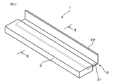
- FIG. 2 is a perspective view of a cleaning blade of Example 1.
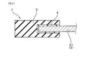
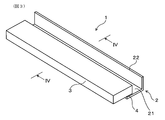
- FIG. It is the figure which showed typically the II-II line cross section in FIG. 10 is a perspective view of a cleaning blade of Example 2.
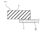
- FIG. 4 is a diagram schematically showing a cross section taken along line IV-IV in FIG. 3.
- the cleaning blade is used to remove residual toner remaining on the surface of the mating member by sliding contact with the mating member in the image forming apparatus employing an electrophotographic system.
- the image forming apparatus include image forming apparatuses such as a copying machine, a printer, a facsimile machine, a multifunction machine, and an on-demand printing machine that employ an electrophotographic system using a charged image.
- the counterpart member include an image carrier such as a photosensitive drum, an intermediate transfer belt, and the like.
- the intermediate transfer belt is used to primarily transfer the toner image carried on the image carrier to the belt, and then secondarily transfer the toner image from the belt to a transfer material such as paper.
- the cleaning blade is a sliding contact portion for sliding the edge portion of the tip of the blade portion into contact with the mating member, and is brought into contact with the surface of the mating member in operation, It can be used to scrape off and remove residual toner on the surface of the mating member that has been carried to the sliding contact portion.
- the cleaning blade has a conductive support having a plate-like portion.
- the conductive support can be composed of a conductive material such as a metal material.
- the plate-like portion can have a shape such as a rectangular shape having a predetermined thickness.
- the length of the plate-like portion in the longitudinal direction can be preferably 230 to 360 mm.
- the thickness of the plate-like portion can be preferably 1.2 to 2 mm.
- the conductive support is connected to a plate-like portion, and can be configured to have an attachment portion for attachment to a member of the image forming apparatus.
- the conductive support may have a shape such as a cross-sectional “L” shape as a whole.
- the cleaning blade has a polyurethane rubber blade portion formed in a plate-like portion.
- the blade portion can be formed on the tip end side in the short direction of the plate-like portion.
- the tip of the plate-like part may be embedded in the blade part.
- the blade portion may be bonded to any one plate surface side of the plate-like portion. In this case, a part of the blade part may be bonded to the tip surface of the plate-like part.
- the blade part contains a potassium salt. That is, in the cleaning blade, the blade portion is made conductive by the potassium salt. Potassium salt functions as an ionic conductive agent. For this reason, the cleaning blade can easily stabilize the volume electrical resistance of the blade portion as compared with the case where carbon black or the like as an electronic conductive agent is added to the blade portion. In addition, the cleaning blade is unlikely to deteriorate in compression set and elongation at the blade portion, and is difficult to increase in hardness.
- the content of the potassium salt in the blade portion is set to 0.3% by mass or more.
- content of potassium salt is a ratio (%) of the mass of the potassium salt contained in a blade part with respect to the whole mass of a blade part.
- the content of the potassium salt in the blade portion is preferably 0.5% by mass or more, more preferably 0.7% by mass or more, and further preferably 1% by mass or more from the viewpoint of ensuring the effect of addition. be able to.
- the content of the potassium salt in the blade portion is less than 10% by mass.
- the content of the potassium salt in the blade portion is preferably 9% by mass or less, more preferably 8% by mass or less, and still more preferably 7% from the viewpoint of the effect of addition, the balance of potassium salt bleed, bloom, production cost, and the like. It can be set to not more than mass%, more preferably not more than 6 mass%, most preferably not more than 5 mass%.
- the anion in the potassium salt is, for example, CF 3 SO 2 C 4 F 9 SO 2 N ⁇ ⁇ nonafluoro-N-[(trifluoromethane) sulfonyl] butanesulfonylamide anion>, (CF 3 SO 2 ) 2 N ⁇ ⁇ bis (trifluoromethanesulfonyl) imide anion>, (FSO 2 ) 2 N ⁇ ⁇ bis (fluorosulfonyl) imidoimide anion>, C 28 H 20 BO 6 ⁇ , AlCl 4 ⁇ , Al 2 Cl 7 ⁇ , NO 3 ⁇ , BF 4 ⁇ , PF 6 ⁇ , CH 3 COO ⁇ , CF 3 COO ⁇ , CF 3 SO 3 ⁇ , (CF 3 SO 2 ) 3 C ⁇ , AsF 6 ⁇ , SbF 6 ⁇ , F (HF) N -, CF 3 CF 2 CF 2 CF 2 CF
- the blade portion may contain one or more potassium salts.
- the anion in the potassium salt is preferably (CF 3 SO 2 ) 2 N ⁇ , CF 3 SO 2 C 4 F 9 SO 2 N ⁇ , C 28 H 20 from the viewpoint of ensuring the above effect.
- BO 6 - may be.
- the cleaning blade is interposed between the plate-like portion and the blade portion, and has a conductive adhesive layer containing a conductive agent.
- the conductive adhesive layer not only bonds the conductive blade portion and the conductive support, but also has a role of electrically connecting the two.
- the conductive adhesive layer is formed on one plate surface of the plate-like portion, the other plate surface, and the blade portion facing each plate surface. It can be interposed between the parts.
- the conductive adhesive layer can be further interposed between the tip surface of the plate-like portion and the portion of the blade portion facing the tip surface.
- the conductive adhesive layer has either one plate surface of the plate-like portion and the blade portion facing the plate surface. It can be interposed between the parts. In this case, the conductive adhesive layer can be further interposed between the tip surface of the plate-like portion and a part of the surface of the blade portion.
- the conductive agent contained in the conductive adhesive layer may be either an electronic conductive agent or an ionic conductive agent. More specifically, examples of the electronic conductive agent include carbon black, carbon nanotube, graphene, metal fine particles, metal oxide fine particles, and the like. These can be used alone or in combination of two or more. Examples of the ionic conductive agent include quaternary ammonium salts, alkali metal salts, alkaline earth metal salts, and the like. These can be used alone or in combination of two or more. As the conductive agent, an electronic conductive agent can be preferably used from the viewpoint of dispersibility in the conductive adhesive layer and the like. Specifically, carbon black can be suitably used as the electronic conductive agent from the viewpoints of dispersibility in the conductive adhesive layer and ease of dispersion control.
- the conductive adhesive layer is preferably 0.1% by mass or more, more preferably 0.5% by mass or more, and even more preferably 1% by mass or more from the viewpoint of imparting conductivity. Can be contained.
- the conductive adhesive layer specifically contains, for example, a conductive agent from the viewpoint of adhesion and the like, preferably 10% by mass or less, more preferably 8% by mass or less, and further preferably 5% by mass or less. be able to.
- the conductive adhesive layer can be composed of a resin adhesive containing a conductive agent.
- the resin adhesive any thermosetting resin adhesive or thermoplastic resin adhesive can be used as long as the blade portion made of polyurethane rubber and the conductive support can be bonded to each other.
- a thermosetting resin adhesive is preferable from the viewpoint of adhesiveness.
- Specific examples of the thermosetting resin adhesive include an epoxy resin adhesive and an acrylic resin adhesive.
- the thickness of the conductive adhesive layer is preferably 0.1 ⁇ m or more, more preferably 0.3 ⁇ m or more, and even more preferably 0.5 ⁇ m or more from the viewpoint of ensuring adhesion.
- the thickness of the conductive adhesive layer is preferably 20 ⁇ m or less, more preferably 15 ⁇ m or less, and even more preferably 10 ⁇ m or less, from the viewpoint of processing stability.
- the volume electrical resistance of the conductive adhesive layer may be equal to or less than the volume electrical resistance of the blade portion. In this case, even if the conductive adhesive layer thinner than the blade portion has a thickness variation, it can be a variation in the volume electrical resistance of the entire cleaning blade. Therefore, it becomes easy to reduce the difference in volume electric resistance between the cleaning blades.
- the volume electrical resistance of the conductive adhesive layer can be preferably smaller than the volume electrical resistance of the blade portion.
- the above-mentioned cleaning blade has a volume electric resistance of preferably less than 1 ⁇ 10 10 ⁇ , more preferably 9 ⁇ 10 9 ⁇ or less, and further preferably from the viewpoint of being advantageous for scraping off residual toner while removing electricity. It can be 8 ⁇ 10 9 ⁇ or less.
- Example 1 The cleaning blade of Example 1 will be described with reference to FIGS. As shown in FIG. 1 and FIG. 2, the cleaning blade 1 of this example has a residual toner (if only toner is left) remaining on the surface of the mating member by sliding contact with the mating member in the image forming apparatus employing the electrophotographic system. In addition, toner external additives are also included).
- the counterpart member is specifically a photosensitive drum in an electrophotographic image forming apparatus.
- the cleaning blade 1 is interposed between the conductive support 2 having the plate-like portion 21, the polyurethane rubber blade portion 3 formed on the plate-like portion 21, and the plate-like portion 21 and the blade portion 3. And a conductive adhesive layer 4 containing a conductive agent (not shown).
- the blade part 3 contains a potassium salt (not shown) of 0.3 mass% or more and less than 10 mass%.
- the conductive support 2 has an attachment portion 22 that is integrally connected to the plate-like portion 21.
- the attachment part 22 is a part for attaching to a member of the image forming apparatus.
- the conductive support 2 is formed in a cross-sectional “L” shape as a whole.
- the blade part 3 is formed on the front end side in the short direction of the plate-like part 21.
- the front end portion of the plate-like portion 21 is embedded in the blade portion 3.
- the conductive adhesive layer 4 is interposed between one plate surface of the plate-like portion 21, the other plate surface, the portion of the blade portion 3 facing each plate surface, and the tip surface of the plate-like portion 21; It is also interposed between the blade portion 3 and the tip surface.
- Example 2 The cleaning blade of Example 2 will be described with reference to FIGS. As shown in FIGS. 3 and 4, in the cleaning blade 1 of this example, the blade portion 3 is bonded to one plate surface side of the plate-like portion 21. The conductive adhesive layer 4 is interposed between one plate surface of the plate-like portion 21 and the portion of the blade portion 3 facing the plate surface. Other configurations are the same as those of the first embodiment.
- polybutylene adipate (Tosoh Corp., “Nipporan 4010”): 87 parts by mass, 1,4-butanediol (Mitsubishi Chemical Corp.) and trimethylolpropane (Guangei Perstorp)
- Low molecular weight polyol mixed at 6 4: 13 parts by mass and triethylenediamine as a catalyst (manufactured by Tosoh Corporation): 0.01 part by mass in a nitrogen atmosphere at 80 ° C. for 1 hour.
- a curing agent solution having a hydroxyl value (OHV) of 210 KOHmg / g
- the above-prepared main agent solution, curing agent solution and ionic conductive agent are blended so that the curing agent solution is 94 parts by mass with respect to 100 parts by mass of the main agent solution, and the ionic conductive agent has a content shown in Table 1.
- the mixture was mixed at 60 ° C. for 3 minutes in a vacuum atmosphere and sufficiently degassed. This prepared each urethane rubber composition used for formation of a blade part in each cleaning blade.
- urethane rubber composition ⁇ Curability of urethane rubber composition> Each urethane rubber composition was applied to a sheet having a thickness of 2 mm and heated at 130 ° C. When the urethane rubber composition is cured in 1 minute, the reactivity of the urethane catalyst by the ionic conductive agent is not hindered, and the curability of the urethane rubber composition is good under the conventional production conditions. did. Further, when the urethane rubber composition does not cure even after 5 minutes, the reactivity of the urethane catalyst by the ionic conductive agent is hindered, and the urethane rubber composition has poor curability under the conventional production conditions. C ”.
- An epoxy resin adhesive (“Aronmite AS-60” manufactured by Toagosei Co., Ltd.) is an electronic conductive agent so that the content of the conductive agent in the formed adhesive layer is the value shown in Table 1. Carbon black (“# 3030B” manufactured by Mitsubishi Chemical Corporation) was added and mixed well for 30 minutes. Thereby, each adhesive used for forming an adhesive layer in each cleaning blade was prepared. For some adhesives, no conductive agent was added for comparison.
- a mold composed of an upper mold and a lower mold was prepared.
- the upper mold and the lower mold are brought close to each other and clamped to form a cavity having a size corresponding to two substantially long plate-like blade portions.
- the cavity is provided with two opposing storage portions.
- Each of these accommodating portions is configured such that a plate-like portion of a conductive support made of a long metal plate (plate thickness: 2 mm) bent into an L-shaped cross section can be arranged.
- a predetermined adhesive was applied to the front and back plate-like surfaces and the tip surface of the tip portion of the plate-like portion of the conductive support so as to have the thickness of the adhesive layer shown in Table 1 described later.
- coating width was made into the range to 2 mm from the front end surface of a plate-shaped part to a base end side.
- a conductive support coated with an adhesive is set in each housing portion of the mold, and after clamping, a predetermined urethane rubber composition is injected into the cavity and heated at 130 ° C. for 5 minutes. Thus, the urethane rubber composition was cured. Thereafter, the molded body was taken out from the mold and cut into two pieces to have a predetermined size. This produced a cleaning blade sample in which the blade portion (thickness 2 mm) made of polyurethane rubber and the conductive support were integrated via the adhesive layer.
- the curability of the urethane rubber composition was “C” evaluation, a cleaning blade sample was prepared by heating for more than 5 minutes until it was cured at 130 ° C.
- Table 1 summarizes the detailed configuration and evaluation results of each cleaning blade.
- sample 2C the content of potassium salt in the blade part exceeds the specified range. Therefore, the sample 2C cannot suppress the bleed and bloom of the ion conductive agent.
- Samples 3C to 6C use ionic conductive agents other than potassium salts. Therefore, in these samples, the reactivity of the urethane catalyst is inhibited, and the curability of the urethane rubber composition is poor under the conventional production conditions.
- Sample 7C has no conductivity because the adhesive layer does not contain a conductive agent. Therefore, it is difficult for sample 7C to scrape off the residual toner while removing the charge.
Landscapes
- Physics & Mathematics (AREA)
- General Physics & Mathematics (AREA)
- Cleaning In Electrography (AREA)
Priority Applications (2)
| Application Number | Priority Date | Filing Date | Title |
|---|---|---|---|
| CN201680034190.6A CN107710078A (zh) | 2015-09-30 | 2016-08-24 | 清洁刮板 |
| US15/865,497 US20180150018A1 (en) | 2015-09-30 | 2018-01-09 | Cleaning blade |
Applications Claiming Priority (2)
| Application Number | Priority Date | Filing Date | Title |
|---|---|---|---|
| JP2015-192404 | 2015-09-30 | ||
| JP2015192404A JP6537949B2 (ja) | 2015-09-30 | 2015-09-30 | クリーニングブレード |
Related Child Applications (1)
| Application Number | Title | Priority Date | Filing Date |
|---|---|---|---|
| US15/865,497 Continuation US20180150018A1 (en) | 2015-09-30 | 2018-01-09 | Cleaning blade |
Publications (1)
| Publication Number | Publication Date |
|---|---|
| WO2017056795A1 true WO2017056795A1 (ja) | 2017-04-06 |
Family
ID=58423234
Family Applications (1)
| Application Number | Title | Priority Date | Filing Date |
|---|---|---|---|
| PCT/JP2016/074674 Ceased WO2017056795A1 (ja) | 2015-09-30 | 2016-08-24 | クリーニングブレード |
Country Status (4)
| Country | Link |
|---|---|
| US (1) | US20180150018A1 (enExample) |
| JP (1) | JP6537949B2 (enExample) |
| CN (1) | CN107710078A (enExample) |
| WO (1) | WO2017056795A1 (enExample) |
Families Citing this family (1)
| Publication number | Priority date | Publication date | Assignee | Title |
|---|---|---|---|---|
| JP6831736B2 (ja) | 2017-03-30 | 2021-02-17 | 株式会社アルファ | ステアリングロック装置 |
Citations (7)
| Publication number | Priority date | Publication date | Assignee | Title |
|---|---|---|---|---|
| JPH07113040A (ja) * | 1993-10-15 | 1995-05-02 | Fukoku Co Ltd | イオン伝導性を有する複写機用ブレード |
| JP2001074034A (ja) * | 1999-09-02 | 2001-03-23 | Tokai Rubber Ind Ltd | 導電性ロール |
| JP2003140427A (ja) * | 2001-08-23 | 2003-05-14 | Tokai Rubber Ind Ltd | 導電性発泡部材 |
| JP2007226185A (ja) * | 2006-01-27 | 2007-09-06 | Kyocera Corp | 画像形成装置 |
| JP2008008957A (ja) * | 2006-06-27 | 2008-01-17 | Bando Chem Ind Ltd | 電子写真装置用弾性部材及びその製造方法 |
| JP2011102859A (ja) * | 2009-11-10 | 2011-05-26 | Ricoh Co Ltd | クリーニング装置、画像形成方法及び画像形成装置 |
| JP2012032808A (ja) * | 2010-07-05 | 2012-02-16 | Canon Inc | 画像形成方法 |
Family Cites Families (4)
| Publication number | Priority date | Publication date | Assignee | Title |
|---|---|---|---|---|
| JP4330599B2 (ja) * | 2006-05-25 | 2009-09-16 | バンドー化学株式会社 | 電子写真装置用クリーニングブレード |
| JP5037292B2 (ja) * | 2007-10-09 | 2012-09-26 | 株式会社リコー | クリーニング装置、像担持体ユニット及び画像形成装置 |
| JP5611004B2 (ja) * | 2010-03-30 | 2014-10-22 | キヤノン株式会社 | 電子写真装置用ブレード |
| JP5449447B2 (ja) * | 2012-04-27 | 2014-03-19 | 住友ゴム工業株式会社 | 導電性ローラ |
-
2015
- 2015-09-30 JP JP2015192404A patent/JP6537949B2/ja active Active
-
2016
- 2016-08-24 CN CN201680034190.6A patent/CN107710078A/zh not_active Withdrawn
- 2016-08-24 WO PCT/JP2016/074674 patent/WO2017056795A1/ja not_active Ceased
-
2018
- 2018-01-09 US US15/865,497 patent/US20180150018A1/en not_active Abandoned
Patent Citations (7)
| Publication number | Priority date | Publication date | Assignee | Title |
|---|---|---|---|---|
| JPH07113040A (ja) * | 1993-10-15 | 1995-05-02 | Fukoku Co Ltd | イオン伝導性を有する複写機用ブレード |
| JP2001074034A (ja) * | 1999-09-02 | 2001-03-23 | Tokai Rubber Ind Ltd | 導電性ロール |
| JP2003140427A (ja) * | 2001-08-23 | 2003-05-14 | Tokai Rubber Ind Ltd | 導電性発泡部材 |
| JP2007226185A (ja) * | 2006-01-27 | 2007-09-06 | Kyocera Corp | 画像形成装置 |
| JP2008008957A (ja) * | 2006-06-27 | 2008-01-17 | Bando Chem Ind Ltd | 電子写真装置用弾性部材及びその製造方法 |
| JP2011102859A (ja) * | 2009-11-10 | 2011-05-26 | Ricoh Co Ltd | クリーニング装置、画像形成方法及び画像形成装置 |
| JP2012032808A (ja) * | 2010-07-05 | 2012-02-16 | Canon Inc | 画像形成方法 |
Also Published As
| Publication number | Publication date |
|---|---|
| JP2017067971A (ja) | 2017-04-06 |
| CN107710078A (zh) | 2018-02-16 |
| JP6537949B2 (ja) | 2019-07-03 |
| US20180150018A1 (en) | 2018-05-31 |
Similar Documents
| Publication | Publication Date | Title |
|---|---|---|
| JP4257771B2 (ja) | 導電性ブレード | |
| JP6463255B2 (ja) | 電子写真用部材および画像形成装置 | |
| KR101216263B1 (ko) | 대전 롤러, 프로세스 카트리지 및 전자 사진 장치 | |
| KR101630100B1 (ko) | 현상 부재와 그 제조 방법 및 전자 사진 화상 형성 장치 | |
| KR101581519B1 (ko) | 이온 도전성 수지 및 전자 사진용 도전성 부재 | |
| KR101496589B1 (ko) | 도전 부재, 프로세스 카트리지 및 전자 사진 화상 형성 장치 | |
| CN1321427C (zh) | 半导电性橡胶部件 | |
| CN101067731B (zh) | 导电性辊 | |
| CN102372917A (zh) | 电子照相设备用导电性橡胶组合物及使用其的带电辊 | |
| JP6537949B2 (ja) | クリーニングブレード | |
| JP6502964B2 (ja) | クリーニングブレード | |
| JP4509274B2 (ja) | 導電部材 | |
| CN102419532B (zh) | 充电元件,处理盒,以及成像装置 | |
| JP5190876B2 (ja) | 導電性ゴム部材 | |
| JP6106553B2 (ja) | 紙送り用ローラ | |
| JP5724087B2 (ja) | 導電性ゴム部材及び帯電ロール | |
| CN102033459A (zh) | 带电辊 | |
| JP6650809B2 (ja) | クリーニングブレード | |
| JP2003202750A (ja) | 現像ロール | |
| JP3140166U (ja) | 導電性シリコーンローラ | |
| JP5541316B2 (ja) | 電気レオロジーゲルおよびこれを用いた保持具 | |
| JP5002301B2 (ja) | 導電性ゴム組成物及びそれを用いてなる導電性ロール | |
| JP6224975B2 (ja) | 導電性材料 | |
| JP2002040896A (ja) | 導電性ブレード | |
| JPH07113040A (ja) | イオン伝導性を有する複写機用ブレード |
Legal Events
| Date | Code | Title | Description |
|---|---|---|---|
| 121 | Ep: the epo has been informed by wipo that ep was designated in this application |
Ref document number: 16850971 Country of ref document: EP Kind code of ref document: A1 |
|
| DPE1 | Request for preliminary examination filed after expiration of 19th month from priority date (pct application filed from 20040101) | ||
| NENP | Non-entry into the national phase |
Ref country code: DE |
|
| 122 | Ep: pct application non-entry in european phase |
Ref document number: 16850971 Country of ref document: EP Kind code of ref document: A1 |