WO2017056733A1 - 二次電池 - Google Patents
二次電池 Download PDFInfo
- Publication number
- WO2017056733A1 WO2017056733A1 PCT/JP2016/073219 JP2016073219W WO2017056733A1 WO 2017056733 A1 WO2017056733 A1 WO 2017056733A1 JP 2016073219 W JP2016073219 W JP 2016073219W WO 2017056733 A1 WO2017056733 A1 WO 2017056733A1
- Authority
- WO
- WIPO (PCT)
- Prior art keywords
- support member
- battery
- electrode group
- secondary battery
- external terminal
- Prior art date
- Legal status (The legal status is an assumption and is not a legal conclusion. Google has not performed a legal analysis and makes no representation as to the accuracy of the status listed.)
- Ceased
Links
Images




Classifications
-
- H—ELECTRICITY
- H01—ELECTRIC ELEMENTS
- H01M—PROCESSES OR MEANS, e.g. BATTERIES, FOR THE DIRECT CONVERSION OF CHEMICAL ENERGY INTO ELECTRICAL ENERGY
- H01M50/00—Constructional details or processes of manufacture of the non-active parts of electrochemical cells other than fuel cells, e.g. hybrid cells
- H01M50/50—Current conducting connections for cells or batteries
- H01M50/572—Means for preventing undesired use or discharge
- H01M50/574—Devices or arrangements for the interruption of current
-
- H—ELECTRICITY
- H01—ELECTRIC ELEMENTS
- H01M—PROCESSES OR MEANS, e.g. BATTERIES, FOR THE DIRECT CONVERSION OF CHEMICAL ENERGY INTO ELECTRICAL ENERGY
- H01M10/00—Secondary cells; Manufacture thereof
- H01M10/05—Accumulators with non-aqueous electrolyte
- H01M10/058—Construction or manufacture
- H01M10/0587—Construction or manufacture of accumulators having only wound construction elements, i.e. wound positive electrodes, wound negative electrodes and wound separators
-
- H—ELECTRICITY
- H01—ELECTRIC ELEMENTS
- H01M—PROCESSES OR MEANS, e.g. BATTERIES, FOR THE DIRECT CONVERSION OF CHEMICAL ENERGY INTO ELECTRICAL ENERGY
- H01M50/00—Constructional details or processes of manufacture of the non-active parts of electrochemical cells other than fuel cells, e.g. hybrid cells
- H01M50/40—Separators; Membranes; Diaphragms; Spacing elements inside cells
- H01M50/489—Separators, membranes, diaphragms or spacing elements inside the cells, characterised by their physical properties, e.g. swelling degree, hydrophilicity or shut down properties
-
- Y—GENERAL TAGGING OF NEW TECHNOLOGICAL DEVELOPMENTS; GENERAL TAGGING OF CROSS-SECTIONAL TECHNOLOGIES SPANNING OVER SEVERAL SECTIONS OF THE IPC; TECHNICAL SUBJECTS COVERED BY FORMER USPC CROSS-REFERENCE ART COLLECTIONS [XRACs] AND DIGESTS
- Y02—TECHNOLOGIES OR APPLICATIONS FOR MITIGATION OR ADAPTATION AGAINST CLIMATE CHANGE
- Y02E—REDUCTION OF GREENHOUSE GAS [GHG] EMISSIONS, RELATED TO ENERGY GENERATION, TRANSMISSION OR DISTRIBUTION
- Y02E60/00—Enabling technologies; Technologies with a potential or indirect contribution to GHG emissions mitigation
- Y02E60/10—Energy storage using batteries
-
- Y—GENERAL TAGGING OF NEW TECHNOLOGICAL DEVELOPMENTS; GENERAL TAGGING OF CROSS-SECTIONAL TECHNOLOGIES SPANNING OVER SEVERAL SECTIONS OF THE IPC; TECHNICAL SUBJECTS COVERED BY FORMER USPC CROSS-REFERENCE ART COLLECTIONS [XRACs] AND DIGESTS
- Y02—TECHNOLOGIES OR APPLICATIONS FOR MITIGATION OR ADAPTATION AGAINST CLIMATE CHANGE
- Y02P—CLIMATE CHANGE MITIGATION TECHNOLOGIES IN THE PRODUCTION OR PROCESSING OF GOODS
- Y02P70/00—Climate change mitigation technologies in the production process for final industrial or consumer products
- Y02P70/50—Manufacturing or production processes characterised by the final manufactured product
Definitions
- the present invention relates to a secondary battery.
- aqueous batteries such as lead batteries, nickel-cadmium batteries and nickel-hydrogen batteries have been mainstream.
- lithium ion secondary batteries having a high energy density have attracted attention, and their research, development, and commercialization are rapidly progressing.
- electric vehicles (EV) and hybrid electric vehicles (HEV) that assist part of driving with electric motors have been developed by each automobile manufacturer due to global warming and depleted fuel problems. Secondary batteries are being demanded.
- a prismatic lithium ion secondary battery having a flat box type battery container is excellent in volumetric efficiency when packed into a pack, so that the demand as a power source mounted on HEV, EV, or other devices increases.
- the pressure inside the battery container may increase due to, for example, overcharge, excessive temperature rise, or damage due to external force.
- a non-aqueous electrolyte secondary battery having a current interrupting mechanism that interrupts current is known (for example, see Patent Document 1 below).
- the non-aqueous electrolyte secondary battery described in Patent Document 1 is connected to an electrode body housed in an outer can, a sealing plate that seals the opening of the outer can, and a current collector plate of either positive or negative electrode A current collecting tab member; and an external electrode terminal protruding outward from the sealing plate. Further, the nonaqueous electrolyte secondary battery is provided on the battery inner side from the sealing plate and on the battery outer side from the current collecting tab member, and is electrically connected to the external electrode terminal, so that the battery internal pressure is increased. A diaphragm is sometimes provided that deforms outward from the battery.
- the non-aqueous electrolyte secondary battery further includes a fragile portion that is broken by a diaphragm.
- the weak part is connected to the battery inner surface of the diaphragm, and the periphery is connected to the current collecting tab member located below the diaphragm. When the diaphragm is deformed and floats, it breaks and cuts off the power to the diaphragm. To do.
- the nonaqueous electrolyte secondary battery further includes a current collecting tab holder into which a part of the current collecting tab member is inserted.
- the current collecting tab member includes a plate-like insertion portion having the weakened portion and a current collecting plate connecting portion connected to one current collecting plate.
- the current collecting tab holder is insulative and has a tab receiving portion into which the insertion portion of the current collecting tab member is inserted. Holder holes are formed on both the inner surface and the outer surface of the tab receiving portion so as to overlap the fragile portion when the insertion portion is inserted.
- the diaphragm is disposed on the battery outer side of the tab receiving portion so as to cover the holder hole, and a bottom surface of the central portion is energized to the weak portion through the holder hole. Connected as possible.
- Patent Document 1 describes that the above-described configuration provides an effect of preventing the weak part from being unnecessarily broken due to an impact or the like and interrupting energization (safety device malfunction).
- the current collecting tab member connected to the electrode body is collected. Vibration is directly transmitted from the electric plate connection portion to the insertion portion, or stress such as torsion acts. Due to the vibration and stress acting on the insertion portion, the weak portion of the insertion portion may be damaged or broken, and the current interruption mechanism may malfunction.
- the present invention has been made in view of the above-described problems, and provides a secondary battery that is excellent in vibration resistance and impact resistance and that can reliably shut off a current path when the internal pressure of a battery container increases. For the purpose.
- a secondary battery of the present invention includes an electrode group, a battery container that accommodates the electrode group, and an external terminal that is disposed on the outer surface of the battery container and is electrically connected to the electrode group. And a current interrupting portion having a weakened portion provided in a current path between the external terminal and the electrode group, wherein the secondary battery is disposed on the first surface of the battery container.
- the secondary battery of the present invention has excellent vibration resistance and impact resistance, and the current path can be reliably and stably interrupted when the internal pressure of the battery container increases.
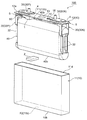
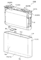
- FIG. 1 is a perspective view of a secondary battery according to an embodiment of the present invention.
- the disassembled perspective view of the secondary battery shown in FIG. The expanded sectional view of the electric current interruption part of the secondary battery shown in FIG.
- the disassembled perspective view of the electrode group of the secondary battery shown in FIG. Sectional drawing which follows the width direction of the secondary battery shown in FIG. Sectional drawing which follows the width direction which shows the modification 1 of the secondary battery shown in FIG.
- FIG. 4 is an exploded perspective view showing a second modification of the secondary battery shown in FIG. 2. Sectional drawing in alignment with the thickness direction of the secondary battery of the modification 2 shown in FIG.
- FIG. 1 is a perspective view of a secondary battery 100 according to an embodiment of the present invention.
- FIG. 2 is an exploded perspective view of the secondary battery 100 shown in FIG.
- the secondary battery 100 of the present embodiment is mainly connected to the electrode group 40, the battery container 10 that houses the electrode group 40, and the electrode group 40 that is disposed on the outer surface of the battery container 10.
- An external terminal 20 and a current interrupting unit 50 having a weakened part 53 (see FIG. 3) provided in a current path between the external terminal 20 and the electrode group 40 are provided.
- the secondary battery 100 of the present embodiment is disposed on the first surface F1 of the battery container 10 and faces the first support member 1 that supports the electrode group 40 and the first surface F1.
- a second support member 2 that is disposed on the second surface F2 of the battery container 10 and supports the electrode group 40 formed separately from the first support member 1, and includes the first support member 1 and the second support member 2.
- At least one of the supporting members 2 is an elastic member.
- the secondary battery 100 of this embodiment is, for example, a prismatic lithium ion secondary battery, and includes a flat rectangular battery container 10.
- the battery container 10 includes a rectangular box-shaped battery can 11 having an opening 11 d at the top, and a rectangular plate-shaped battery lid 12 that seals the opening 11 d of the battery can 11.
- the battery can 11 and the battery lid 12 are made of, for example, aluminum or an aluminum alloy.
- the battery lid 12 is cleaved at an intermediate portion between the external terminals 20 at both ends in the longitudinal direction when the internal pressure of the battery container 10 rises above a predetermined pressure to reduce the internal pressure of the battery container 10.
- a liquid injection hole 14 for injecting a non-aqueous electrolyte into the battery container 10 and a liquid injection plug 15 for sealing the liquid injection hole 14.
- an electrode group 40 fixed to the battery cover 12 and covered with an insulating sheet (not shown) is inserted from the opening 11d of the battery can 11, and the opening 11d of the battery can 11 is formed by laser welding, for example.
- the battery assembly 12 is sealed with the electrode group 40 accommodated therein.
- the direction along the long side of the rectangular battery lid 12 in plan view is the longitudinal direction or width direction of the battery case 10, and the direction along the short side of the battery lid 12 is the short side direction or thickness of the battery case 10.
- the direction perpendicular to the battery lid 12 is referred to as the height direction of the battery container 10.
- the external terminal 20 is disposed on the outer surface 12a of the battery lid 12 with the resin gasket 3 (see FIGS. 3 and 4) having electrical insulation and the external insulating member 4 interposed therebetween.
- the external terminal 20 includes a positive external terminal 20P disposed at one end in the width direction of the battery case 10 and a negative external terminal 20N disposed at the other end in the width direction of the battery case 10.
- the positive external terminal 20P is made of, for example, aluminum or an aluminum alloy
- the negative external terminal 20N is made of, for example, copper or a copper alloy.
- the secondary battery 100 of the present embodiment includes an insulating member 5 fixed to the inner surface 12 b of the battery lid 12, and a current collector fixed to the battery lid 12 via the insulating member 5 and joined to the electrode group 40. And a plate 30.
- the current collector plate 30 includes a positive electrode current collector plate 30P that electrically connects the positive electrode external terminal 20P and the positive electrode 41 (see FIG. 5) of the electrode group 40, a negative electrode external terminal 20N, and the negative electrode 42 ( And a negative electrode current collector plate 30N that is electrically connected to each other.
- the positive electrode current collector plate 30P is made of, for example, aluminum or an aluminum alloy
- the negative electrode current collector plate 30N is made of, for example, copper or a copper alloy.
- FIG. 3 is an enlarged cross-sectional view of the current interrupting unit 50 of the secondary battery 100 shown in FIG.
- FIG. 4 is an exploded perspective view of the current interrupting part 50 and its peripheral members shown in FIG.
- the current interrupting part 50 is disposed between the external terminal 20 and the electrode group 40, constitutes a current path between the external terminal 20 and the electrode group 40, and includes a fragile part 53 provided in the current path.
- the current interrupting unit 50 is a member that forms a current path between the positive external terminal 20P and the electrode group 40, and includes a conductive plate 51, a diaphragm 52, and a positive current collector 30P.
- the fragile portion 53 is provided in the positive electrode current collector plate 30P.
- the conductive plate 51 has, for example, a planar shape such as a circular shape, an oval shape, an elliptical shape, a field track shape having a circular arc portion and a straight line portion corresponding to the planar shape of the diaphragm 52, and a through hole 51a is formed in the center portion. It is the plate-shaped member made.
- the conductive plate 51 is made of a metal having conductivity, and can be made of aluminum or an aluminum alloy, for example, similarly to the positive electrode external terminal 20P and the positive electrode current collector plate 30P.
- the diaphragm 52 has, for example, a planar shape such as a circle, an oval, an ellipse, or a field track shape corresponding to the planar shape of the conductive plate 51.
- the diaphragm 52 is formed into a dome shape or a bowl shape having a cavity on the inside by, for example, bulging a metal thin plate having conductivity by press working or the like.
- the diaphragm 52 can be made of aluminum or an aluminum alloy, for example, similarly to the conductive plate 51 and the positive electrode current collector plate 30P.
- the diaphragm 52 includes a flange-shaped edge portion 52a bent so as to be engaged with the annular groove 51b of the conductive plate 51, and a dome-shaped or bowl-shaped pressure receiving portion that bulges from the edge portion 52a toward the current collecting plate 30. 52b, and a protrusion 52c having a flat bottom surface protruding in a step shape from the bottom of the pressure receiving portion 52b adjacent to the current collector 30 toward the current collector 30.
- the positive electrode current collector plate 30 ⁇ / b> P has a rectangular flat plate-like base portion 31 and a pair of plate-like terminal portions 32.
- the pair of terminal portions 32 are formed in an elongated plate shape that hangs down from the end portion on the outer side in the width direction of the battery case 10 on the side corresponding to the long side of the rectangular base 31 in plan view toward the bottom surface 10b of the battery case 10. Is formed.
- the base 31 that is rectangular in plan view has through-holes 31a at four corners and a recess 31b at the center.
- the concave portion 31b is formed in a bowl shape having an inclined surface along the dome shape of the pressure receiving portion 52b of the diaphragm 52 facing the base portion 31.
- the bottom of the recess 31b has a planar shape such as a circle, an oval, or a field track that corresponds to the planar shape of the protrusion 52c of the diaphragm 52, for example.
- the bottom part of the recess 31b provided in the base 31 of the positive electrode current collector plate 30P is a thin part 31c that is thinner than a part where the recess 31b is not formed or a part corresponding to the inclined surface of the recess 31b.
- the positive electrode current collector plate 30P has an annular groove 31d at the center of the thin portion 31c of the base portion 31.
- the bottom portion of the annular groove 31d is thinner than the thin portion 31c, and is a fragile portion 53 of the current interrupting portion 50 provided in the current path between the external terminal 20 and the electrode group 40.
- the resin-made external insulating member 4 having insulating properties is disposed on the outer surface 12 a of the battery lid 12.
- an insulating resin gasket 3 is disposed inside the opening 4 a of the external insulating member 4 and engaged with the through hole 12 c of the battery lid 12.
- a bus bar fixing bolt 21 is inserted into the through hole 20a of the plate-like portion of the positive external terminal 20P and disposed on the external insulating member 4, and the through hole 3a of the gasket 3 and the through hole of the battery lid 12 are disposed.
- the cylindrical connection part 20b of the positive electrode external terminal 20P is inserted into 12c.
- the conductive plate 51 is disposed with the insulating member 5 interposed on the inner surface 12b of the battery lid 12, and the connecting portion of the positive external terminal 20P is connected to the through hole 5a of the insulating member 5 and the through hole 51a of the conductive plate 51. 20b is inserted.
- the distal end portion of the connecting portion 20b of the positive electrode external terminal 20P is plastically deformed to increase the diameter, and an annular caulking portion 20c is formed at the distal end portion of the connecting portion 20b.
- the caulking portion 20c and the conductive plate 51 are joined by laser welding, for example. Thereby, each member inserted through the connecting portion 20b of the positive external terminal 20P is caulked and fixed to the battery lid 12, and the positive external terminal 20P and the conductive plate 51 are contacted or joined by the caulking portion 20c and the conductive plate 51. Are electrically connected.
- the flange-like edge 52a of the diaphragm 52 is engaged with the annular groove 51b of the conductive plate 51, and the diaphragm 52 and the conductive plate 51 are joined over the entire circumference of the edge 52a, for example, by laser welding.
- the diaphragm 52 and the conductive plate 51 are electrically connected, and the diaphragm 52 and the conductive plate 51 are sealed.
- the protrusions 5b of the insulating member 5 are inserted into the through holes 31a at the four corners of the base 31 of the positive current collector plate 30P, and the inner side of the annular weak portion 53 provided on the base 31 of the positive current collector 30P.
- the protruding portion 52c of the diaphragm 52 is pressed against the thin portion 31c with a predetermined surface pressure. In this state, for example, the tip of the protrusion 5b of the insulating member 5 is heated to expand the diameter, and then cooled and heat-caulked or thermally welded to form the caulking portion 5c.
- the thin portion 31c inside the annular fragile portion 53 provided in the base portion 31 is pressed against the bottom surface of the projecting portion 52c of the diaphragm 52 with a predetermined surface pressure so as to be in close contact therewith.
- the diaphragm 52 and the positive electrode current collector plate 30P are electrically connected to each other by being fixed to the inner surface 12b of the battery lid 12 via the insulating member 5.
- the thin portion 31c inside the annular fragile portion 53 provided on the base portion 31 of the positive current collector plate 30P and the bottom surface of the protruding portion 52c of the diaphragm 52 are joined by, for example, laser welding to form a joined portion.
- the current blocking portion 50 having the current path between the positive external terminal 20P and the electrode group 40 and the weakened portion 53 provided in the current path by the conductive plate 51, the diaphragm 52, and the positive current collecting plate 30P. Is configured. That is, the positive electrode external terminal 20P is connected to the foil exposed portion 41b (see FIG.
- the positive electrode 41 constituting the electrode group 40 via the conductive plate 51, the diaphragm 52, and the positive electrode current collector plate 30P. Further, the positive external terminal 20P, the conductive plate 51, the diaphragm 52, and the positive current collecting plate 30P are electrically insulated from the battery lid 12 by the gasket 3, the external insulating member 4, and the insulating member 5.
- the negative electrode external terminal 20N side of the secondary battery 100 does not have the conductive plate 51 and the diaphragm 52.
- the base 31 of the negative electrode current collector plate 30N does not have the concave portion 31b, the thin portion 31c, and the fragile portion 53, and has a through hole through which the connecting portion 20b of the negative electrode external terminal 20N is inserted.
- the insulating member 5 disposed between the base 31 of the negative electrode current collector plate 30N and the battery lid 12 does not have a recess for disposing the conductive plate 51 and the diaphragm 52.
- the external insulating member 4 and the gasket 3 are arranged in the same manner as the positive electrode external terminal 20P.
- the connecting portion 20b of the negative electrode external terminal 20N is insulated from the through hole 3a of the gasket 3, the opening portion 4a of the external insulating member 4, the through hole 12c of the battery lid 12, and the connecting portion 20b of the positive electrode external terminal 20P.
- the through hole 5a of the member 5 and the through hole of the base 31 of the negative electrode current collector plate 30N are inserted, and a caulking portion 20c is formed at the tip. Further, the caulking portion 20c is joined to the base portion 31 of the negative electrode current collector plate 30N by, for example, laser welding.
- the gasket 3, the external insulating member 4, the insulating member 5, and the negative electrode current collector plate 30N are caulked and fixed to the battery lid 12, and the negative electrode external terminal 20N is electrically connected to the negative electrode current collector plate 30N. 12 is electrically insulated. Thereafter, the terminal portion 32 of the positive current collector plate 30P and the terminal portion 32 of the negative current collector plate 30N are connected to the electrode group 40, respectively.
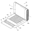
- FIG. 5 is an exploded perspective view in which a part of the electrode group 40 shown in FIG. 2 is developed.
- the electrode group 40 is manufactured, for example, by winding a belt-like positive electrode 41 and a negative electrode 42 with belt-like separators 43 and 44 interposed therebetween and press-molding. That is, in the electrode group 40 of the present embodiment, the flat portion 40a in which the positive electrode 41 and the negative electrode 42 are flatly stacked, and the positive electrode 41 and the negative electrode 42 are curved in a semicylindrical shape at both ends of the flat portion 40a. And a flat wound electrode group having a curved portion 40b laminated.
- the configuration of the electrode group 40 is not limited to the wound electrode group, and for example, a stacked electrode group may be used.
- the electrode group 40 is wound, for example, while applying a tensile load of about 10 N in the extending direction of a strip-shaped laminate in which the positive electrode 41 and the negative electrode 42 are laminated with the separators 43 and 44 interposed therebetween. At this time, the electrode group 40 performs meandering control so that the end portions of the positive electrode 41, the negative electrode 42, and the separators 43 and 44 at both ends in the width direction of the strip-shaped laminate, that is, the winding axis A direction, are in a fixed position. While being beaten.
- the positive electrode 41 has a positive electrode mixture layer 41a formed on both surfaces of the positive foil, and has a foil exposed portion 41b in which the positive foil is exposed on one side edge in the width direction, that is, the winding axis A direction of the electrode group 40.
- the negative electrode 42 has a negative electrode mixture layer 42a formed on both surfaces of the negative electrode foil, and has a foil exposed portion 42b in which the negative electrode foil is exposed on the other side edge in the width direction, that is, the winding axis A direction of the electrode group 40.
- the foil exposed portions 41b and 42b of the positive electrode 41 and the negative electrode 42 are wound so as to be positioned on opposite sides in the width direction, that is, the winding axis A direction.
- the positive electrode 41 can be produced, for example, by the following procedure. First, 10 parts by weight of flaky graphite as a conductive material and 10 parts by weight of polyvinylidene fluoride (hereinafter referred to as PVDF) as a binder with respect to 100 parts by weight of lithium manganate (chemical formula LiMn 2 O 4 ) as a positive electrode active material. And). To this, N-methylpyrrolidone (hereinafter referred to as NMP) is added as a dispersion solvent and kneaded to prepare a positive electrode mixture. This positive electrode mixture is applied to both surfaces of an aluminum foil having a thickness of about 20 ⁇ m, which is a positive foil, leaving the exposed foil portions 41b. Thereafter, the positive electrode layer 41 having a thickness of, for example, about 90 ⁇ m can be obtained by drying, pressing, and cutting, and the thickness of the positive electrode mixture layer 41a not including the aluminum foil.
- PVDF polyvinylidene fluoride
- NMP N-methylpyrrol
- lithium manganate is used as the positive electrode active material.
- another lithium manganate having a spinel crystal structure or a lithium manganese composite oxide or layered crystal structure in which a part is substituted or doped with a metal element Lithium cobaltate, lithium titanate, or a lithium-metal composite oxide obtained by substituting or doping a part thereof with a metal element may be used.
- the negative electrode 42 can be produced, for example, by the following procedure. First, 10 parts by weight of PVDF as a binder is added to 100 parts by weight of amorphous carbon powder as a negative electrode active material, and NMP is added and kneaded as a dispersion solvent to prepare a negative electrode mixture. This negative electrode mixture is applied on both sides of a copper foil having a thickness of about 10 ⁇ m, which is a negative electrode foil, leaving the exposed foil portions 42b. Thereafter, drying, pressing, and cutting can be performed to obtain the negative electrode 42 having a thickness of the negative electrode mixture layer 42a that does not include the copper foil, for example, about 70 ⁇ m.
- amorphous carbon is exemplified as the negative electrode active material, but the negative electrode active material is not particularly limited.
- the negative electrode active material is not particularly limited.
- the particle shape of the negative electrode active material is not particularly limited, and may be, for example, a scale shape, a spherical shape, a fiber shape, a lump shape, or the like.
- PVDF is exemplified as the binder, but polytetrafluoroethylene (PTFE), polyethylene, polystyrene, polybutadiene, butyl rubber, nitrile rubber, styrene butadiene rubber, polysulfide rubber, nitrocellulose, cyanoethyl cellulose.
- PTFE polytetrafluoroethylene
- polyethylene polystyrene
- polybutadiene butyl rubber
- nitrile rubber styrene butadiene rubber
- polysulfide rubber nitrocellulose
- cyanoethyl cellulose cyanoethyl cellulose.
- Various polymers such as latex, acrylonitrile, vinyl fluoride, vinylidene fluoride, propylene fluoride, chloroprene fluoride, and acrylic resin, and mixtures thereof can be used.
- the separators 43 and 44 are made of an insulating material having a microporous property, for example, made of polyethylene, and have a role of insulating the positive electrode 41 and the negative electrode 42.
- the negative electrode mixture layer 42a of the negative electrode 42 is larger in the width direction than the positive electrode mixture layer 41a of the positive electrode 41, so that the positive electrode mixture layer 41a is always sandwiched between the negative electrode mixture layer 42a. .
- the foil exposed portions 41 b and 42 b of the positive electrode 41 and the negative electrode 42 are bundled in the flat portion 40 a of the electrode group 40. As shown in FIG. 2, the foil exposed portions 41b and 42b are bonded and fixed to the terminal portions 32 of the positive electrode current collector plate 30P and the negative electrode current collector plate 30N, respectively, by, for example, resistance welding or ultrasonic welding. . Thus, in the electrode group 40, the positive electrode 41 and the negative electrode 42 are electrically connected to the positive current collector plate 30P and the negative current collector plate 30N, respectively.
- the separators 43 and 44 alternately stacked with the positive electrode 41 and the negative electrode 42 are defined to have a width that exposes the foil exposed portions 41b and 42b on both sides, though wider than the width of the negative electrode mixture layer 42a. As a result, the foil exposed portions 41b and 42b are not hindered when being bundled and welded.
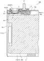
- FIG. 6 is a cross-sectional view along the width direction of the battery case 10 shown in FIG. 1, that is, the longitudinal direction of the battery lid 12.
- the secondary battery 100 of the present embodiment is disposed on the first surface F1 of the battery container 10, and the first support member 1 that supports the electrode group 40 and the battery that faces the first surface F1.
- a second support member 2 that is disposed on the second surface F2 of the container 10 and supports the electrode group 40 that is formed separately from the first support member 1, and includes the first support member 1 and the second support member. At least one of the members 2 is an elastic member.
- the first surface F1 of the battery container 10 on which the first support member 1 is disposed is the inner surface 12b of the battery lid 12 that constitutes the battery container 10.
- the second surface F ⁇ b> 2 of the battery container 10 on which the second support member 2 is disposed is an inner bottom surface 11 b of the battery can 11 constituting the battery container 10.
- the first surface F1 of the battery container 10, that is, the inner surface 12b of the battery lid 12, and the second surface F2 of the battery container 10, that is, the inner bottom surface 11b of the battery can 11, are The surfaces are opposed to each other in the height direction.
- the first surface F1 and the second surface F2 of the battery container 10 may not be the inner surface 12b of the battery lid 12 and the inner bottom surface 11b of the battery can 11.
- the inner surface of the battery container 10, that is, the inner surface of the narrow side surface 10c along the thickness direction of the flat rectangular battery container 10 may be used.
- a resin material having electrical insulation properties such as polypropylene (PP), polybutylene terephthalate (PBT), polyphenylene sulfide (PPS), or the like can be used.
- a rubber-based material having electrical insulation, solvent resistance, and chemical resistance such as fluorine rubber and ethylene propylene rubber (EPDM) can be used.
- the elastic member means a member that is arranged in an elastically deformed state or that can be elastically deformed in a predetermined case.
- the first support member 1 is made of, for example, the above-described resin material having electrical insulation, similarly to the insulating member 5 between the current collector plate 30 and the battery lid 12.
- the second support member 2 is made of, for example, the rubber material described above.
- the first support member 1 is formed integrally with the insulating member 5 disposed between the positive electrode current collector plate 30 ⁇ / b> P and the battery lid 12, for example. 1 surface F1, that is, the inner surface 12b of the battery lid 12.
- the first support member 1 extends from the insulating member 5 in the width direction of the battery case 10, protrudes toward the curved portion 40b of the electrode group 40 facing the first surface F1 of the battery case 10, and the curved portion 40b. Support.
- the first support member 1 between the inner surface 12b of the battery lid 12 and the curved portion 40b of the electrode group 40 has a substantially rectangular parallelepiped shape, and the surface of the first support member 1 facing the curved portion 40b of the electrode group 40 is It is in contact with the bending portion 40b or opposed to the bending portion 40b with a slight gap.
- the surface of the first support member 1 facing the curved portion 40b of the electrode group 40 may be a flat surface or a curved surface that follows the shape of the curved portion 40b.
- the first support member 1 is not elastically deformed by the force received from the curved portion 40b of the electrode group 40, or is provided with rigidity that is a negligible amount of elastic deformation. It is a rigid member.
- the 1st support member 1 can also be made into the elastic member to which the elasticity elastically deform
- the materials of the insulating member 5 and the first support member 1 are different, for example, they can be separately molded and joined together, or can be integrally molded by two-color molding.
- the second support member 2 is an independent single member as shown in FIG. 2 and is formed in a substantially rectangular parallelepiped shape.
- the second surface F2 of the battery container 10 that is, the battery. It arrange
- FIG. The second support member 2 can be fixed to the second surface F2 of the battery container 10 or the curved portion 40b of the electrode group 40 with, for example, an adhesive tape or an adhesive.
- the second support member 2 is compressed and elastically deformed between the second surface F2 of the battery case 10 and the bending portion 40b of the electrode group 40 facing the second surface F2 of the battery case 10, and the bending portion
- the surface facing 40b is a curved surface along the curved portion 40b.
- the second support member 2 applies an elastic force due to elastic deformation to the curved portion 40b of the electrode group 40 in a direction perpendicular to the second surface F2 of the battery case 10, that is, the inner bottom surface 11b of the battery can 11, and An electrode group 40 is sandwiched between the support member 1 and the support member 1.
- the second support member 2 is an elastic member to which elasticity that is elastically deformed by a force received from the curved portion 40 b of the electrode group 40 when the secondary battery 100 is assembled is provided.
- the first support member 1 is an elastic member
- the second support member 2 may be an elastic member or a rigid member. That is, at least one of the first support member 1 and the second support member 2 may be an elastic member.
- the surface of the second support member 2 that faces the curved portion 40b of the electrode group 40 may be a flat surface or a curved surface that follows the shape of the curved portion 40b. Also good.
- the first support member 1 and the second support member 2 are disposed at a position closer to the current interrupting unit 50 than the center of the battery container 10 in the width direction of the battery container 10. . More specifically, the first support member 1 is adjacent to the center side end of the battery case 10 of the base 31 of the positive current collector plate 30 ⁇ / b> P constituting a part of the current interrupting part 50 in the width direction of the battery case 10. And has a width dimension suitable for supporting the electrode group 40.
- the second support member 2 has at least the position of the first support member 1 in the width direction of the battery container 10 in the height direction of the battery container 10, that is, in the direction perpendicular to the second surface F2 of the battery container 10.
- the electrode group 40 is sandwiched between the first support member 1 and the second support member 2 from both sides in the height direction of the battery container 10 in the vicinity of the positive electrode external terminal 20P where the current interrupting unit 50 is disposed.
- the first support member 1 includes the positive electrode external terminal 20P, the bolt 21, the gasket 3, the external insulating member 4, the insulating member 5, and the conductive plate 51 shown in FIG.
- the battery lid 10 is disposed on the inner surface 12 b of the battery lid 12 that is the first surface F ⁇ b> 1.
- the first support member 1 bundles the positive electrode 41 of the electrode group 40 and the foil exposed portions 41b and 42b of the negative electrode 42 and joins them to the positive current collector 30P and the negative current collector 30N. By doing so, it arrange
- the second support member 2 is formed by bundling the exposed portions 41b and 42b of the positive electrode 41 and the negative electrode 42 of the electrode group 40 shown in FIG. 5 as shown in FIG. 2, and the positive current collector 30P and the negative current collector 30N.
- the electrode group 40 is inserted from the opening 11d of the battery can 11, and the second support member 2 is elastically deformed between the second surface F2 of the battery container 10 and the curved portion 40b of the electrode group 40.
- the opening 11d of the battery can 11 is closed by the battery lid 12, and the battery lid 12 is welded over the entire circumference of the opening 11d of the battery can 11 by laser welding, for example.
- the battery container 10 in which the space between the opening 11d of the battery can 11 and the battery lid 12 is sealed is obtained.
- a non-aqueous electrolyte is injected into the battery container 10 through the liquid injection hole 14 of the battery lid 12, and the liquid injection hole 15 is welded by, for example, laser welding to seal the liquid injection hole 14.
- the secondary battery 100 shown in FIG. 1 is obtained.
- the non-aqueous electrolyte to be injected into the battery container 10 for example, 1 mol of lithium hexafluorophosphate (LiPF 6 ) is mixed into a mixed solution in which ethylene carbonate and dimethyl carbonate are mixed at a volume ratio of 1: 2. A solution dissolved at a concentration of 1 liter can be used.
- the non-aqueous electrolyte is not limited to a lithium salt or an organic solvent.
- a non-aqueous electrolytic solution in which a general lithium salt is used as an electrolyte and this is dissolved in an organic solvent may be used.
- the electrolyte for example, LiClO 4 , LiAsF 6 , LiBF 4 , LiB (C 6 H 5 ) 4 , CH 3 SO 3 Li, CF 3 SO 3 Li, or a mixture thereof can be used.
- the organic solvent include propylene carbonate, ethylene carbonate, 1,2-dimethoxyethane, 1,2-diethoxyethane, ⁇ -butyrolactone, tetrahydrofuran, 1,3-dioxolane, 4-methyl-1,3-dioxolane, Diethyl ether, sulfolane, methyl sulfolane, acetonitrile, propiontonyl, etc. or a mixed solvent of two or more of these may be used, and the mixing ratio is not particularly limited.
- the secondary battery 100 having the above configuration stores the external power supplied to the external terminal 20 in the electrode group 40 via the current interrupting unit 50 and the current collector plate 30, and collects the power stored in the electrode group 40.
- the power is supplied from the external terminal 20 to the external device via the plate 30 and the current interrupting unit 50.
- the base 31 of the positive current collector 30P of the diaphragm 52 of the current interrupting unit 50 The pressure acting on the opposite surface is higher than the pressure acting on the opposite surface.
- the diaphragm 52 becomes concave from the base 31 of the positive current collector plate 30P toward the battery lid 12, for example, to buckle. Plastic deformation.
- a stress acts on the thin portion 31c.
- stress concentrates on the fragile portion 53 around the joint portion of the diaphragm 52 and the thin portion 31c, and the thin portion 31c breaks starting from the fragile portion 53, and the positive current collector 30P constituting the current interrupting portion 50 And the diaphragm 52 are disconnected. Thereby, the current path between the electrode group 40 and the positive electrode external terminal 20P is cut off, and the safety of the secondary battery 100 is ensured.
- the secondary battery 100 may be exposed to vibration or shock during normal use before the current interruption unit 50 operates normally due to the occurrence of the above-described abnormality.
- the electrode body is formed by an insulating plate, a sealing body lead, a diaphragm, and a current collecting tab member fixed to the sealing body via a metal thin film. , Suspended from the sealing body.
- the electrode body may vibrate or swing inside the outer can.
- the secondary battery 100 of the present embodiment includes the electrode group 40, the battery container 10 that houses the electrode group 40, and the electrode group 40 that is disposed on the outer surface of the battery container 10.
- An external terminal 20 that is electrically connected, and a current interrupting part 50 having a weakened part 53 provided in a current path between the external terminal 20 and the electrode group 40 are provided.
- the secondary battery 100 of this embodiment is arrange
- the second support member 2 is disposed on the second surface F2 and supports the electrode group 40 separately from the first support member 1. Furthermore, at least one of the first support member 1 and the second support member 2 is an elastic member.
- the secondary battery 100 when the secondary battery 100 is exposed to vibration or impact, stress acts on the first support member 1 and the second support member 2 from the electrode group 40, and at least one elastic member is elastically deformed.
- vibrations and shocks applied to the secondary battery 100 can be absorbed and mitigated, and vibrations or oscillations of the electrode group 40 can be suppressed.
- the second support member 2 that is an elastic member elastically deforms according to the behavior of the electrode group 40 to absorb and relax vibrations and shocks, The vibration or swing of the electrode group 40 can be suppressed.
- the second support member 2 which is an elastic member, is brought into contact with the electrode group 40 in a state in which the second support member 2 is elastically deformed in advance, so that the elastic force is constantly applied from the second support member 2 to the electrode group 40. can do.
- the vibration or swing of the electrode group 40 when the secondary battery 100 is exposed to vibration or impact can be more effectively suppressed, and the dimensional tolerance of the electrode group 40 can be absorbed.
- the electrode group 40 is supported from different directions by the first support member 1 and the second support member 2 disposed on the first surface F1 and the second surface F2 which are different surfaces of the battery case 10, so that the electrode The vibration or swing of the group 40 can be more effectively suppressed.
- the secondary battery 100 of the present embodiment suppresses vibration or swing of the electrode group 40 by the first support member 1 and the second support member 2 when exposed to vibration or impact.
- the stress acting on the fragile portion 53 of the positive current collector 30P connected to the electrode group 40 can be relaxed.
- rupture of the weak part 53 which are the main structures of the electric current interruption part 50 can be suppressed, and the malfunctioning of the electric current interruption part 50 can be prevented. Therefore, according to the secondary battery 100 of the present embodiment, there is provided the secondary battery 100 that is excellent in vibration resistance and impact resistance, and that can reliably and stably interrupt the current path when the internal pressure of the battery container 10 increases. can do.
- the first surface F1 and the second surface F2 of the battery container 10 are surfaces facing each other. Therefore, the electrode group 40 is opposed to each other by the first support member 1 disposed on the first surface F1 of the battery container 10 and the second support member 2 disposed on the second surface F2 of the battery container 10. The vibration or swinging of the electrode group 40 can be more effectively suppressed by being sandwiched.
- both the first support member 1 and the second support member 2 are elastic members, for example, the elastic coefficients of the first support member 1 and the second support member 2 are individually adjusted, or the first support member
- the elastic force acting on the electrode group 40 from the member 1 and the elastic force acting on the electrode group 40 from the second support member 2 can be individually adjusted. Thereby, the vibration or swing of the electrode group 40 can be more effectively suppressed.
- the electrode group 40 is a flat wound electrode group having a flat portion 40a and curved portions 40b at both ends of the flat portion 40a. Then, the curved portion 40b facing the first surface F1 of the battery case 10 is supported by the first support member 1, and the curved portion 40b facing the second surface F2 of the battery case 10 is supported by the second support member 2.
- the support member 1 and the second support member 2 can be disposed.
- the battery container 10 includes a battery can 11 that houses the electrode group 40 and a battery lid 12 that seals the opening 11d of the battery can 11.
- the surface F ⁇ b> 1 is the inner surface 12 b of the battery lid 12. Therefore, it becomes easy to arrange the first support member 1 on the first surface F1 of the battery container 10. Specifically, for example, before the battery lid 12 is welded to the opening 11 d of the battery can 11 and the battery container 10 is sealed, the first support member 1 is disposed on the inner surface 12 b of the battery lid 12. Can do.
- the secondary battery 100 of the present embodiment has a battery lid 12 that is the first surface F1 of the battery container 10 by the connecting portion 20b of the positive electrode external terminal 20P that penetrates the battery lid 12 that is a part of the battery container 10.
- An insulating member 5 fixed to the inner surface 12b and a positive current collector 30P fixed to the insulating member 5 and connected to the electrode group 40 are provided.
- the weak part 53 of the electric current interruption part 50 is formed in the positive electrode current collecting plate 30P.
- the first support member 1 is formed integrally with the insulating member 5.
- the first support member 1 and the insulating member 5 are bundled together in the step of plastically deforming the tip of the connecting portion 20b of the positive electrode external terminal 20P to form the caulking portion 20c and caulking and fixing the insulating member 5 to the battery lid 12. Then, it can be disposed on the first surface F1 of the battery case 10, that is, the inner surface 12b of the battery lid 12. Therefore, the manufacturing process of the secondary battery 100 can be simplified, the product yield and productivity can be improved, and the manufacturing cost can be reduced. Moreover, the increase in the number of parts of the secondary battery 100 can be suppressed, and the part cost can be reduced.
- the current interruption unit 50 is provided at one end in the width direction of the flat rectangular battery case 10.
- the 1st support member 1 and the 2nd support member 2 are arrange
- FIG. Thereby, compared with the case where the 1st supporting member 1 and the 2nd supporting member 2 are arrange
- the vibration or swinging of the electrode group 40 can be more effectively suppressed.
- the vibration absorption property of the elastic member or Impact absorption can be improved. Further, the elastic coefficient, size and shape of the elastic member can be easily adjusted, and the production of the elastic member can be facilitated.
- the first support member 1 and the second support member 2 have electrical insulation. Therefore, it is possible to prevent the positive electrode or the negative electrode constituting the electrode group 40 from being short-circuited with the battery container 10 via the first support member 1 and the second support member 2.
- the 1st support member 1 and the 2nd support member 2 can be manufactured with the material similar to the external insulation member 4, the gasket 3, or the insulation member 5.
- the secondary battery 100 of the present embodiment it is excellent in vibration resistance and impact resistance, and the current path can be reliably and stably interrupted when the internal pressure of the battery container 10 is increased.
- the secondary battery of the present invention has a battery lid 12 that seals the opening 11d of the battery can 11 that faces the bottom surface 10b of the flat rectangular battery case 10, like the secondary battery 100 of the above-described embodiment.
- the configuration is not limited to the configuration including the external terminal 20.
- the external terminal 20 can also be provided on the narrow side surface 10 c of the battery case 10.
- the opening of the battery can 11 is provided on the surface corresponding to the narrow side surface 10 c of the battery container 10, and the outer surface 12 a of the battery lid 12 that seals the opening of the battery can 11 is used as the narrow side surface 10 c of the battery container 10. It is good.
- the first support member 1 is formed integrally with the insulating member 5 disposed between the battery lid 12 and the conductive plate 51 .
- the first support member 1 may be a single member independent of the insulating member 5. Moreover, you may fix the 1st support member 1 and the 2nd support member 2 to the 1st surface F1 and the 2nd surface F2 of the battery container 10 by insert molding, for example.
- at least one of the first support member 1 and the second support member 2 may be an elastic member made of a leaf spring.
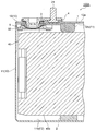
- FIG. 7 is a cross-sectional view corresponding to FIG. 6 showing Modification 1 of the secondary battery 100 described in the above embodiment.
- the first support member 1 is a single member independent of the insulating member 5.
- the 1st support member 1 can be fixed to the 1st surface F1 of the battery container 10 with a double-sided adhesive tape or an adhesive agent, for example.
- the 1st support member 1 can also be fixed to the 1st surface F1 of the battery container 10 by insert molding.
- positioning of the 1st support member 1 can be improved by making the 1st support member 1 a member independent of the insulating member 5.
- FIG. 8 is an exploded perspective view corresponding to FIG. 2 showing a second modification of the secondary battery 100 described in the above embodiment.
- FIG. 9 is a cross-sectional view taken along the thickness direction of the battery container 10 of the secondary battery 100B of Modification 2 shown in FIG.
- the second support member 2B disposed on the second surface F2 of the battery container 10, that is, the inner bottom surface 11b of the battery can 11, is an elastic member made of a leaf spring.
- the second support member 2B is formed of an elastic thin plate, is formed in a partial cylindrical shape along the shape of the curved portion 40b of the electrode group 40, and comes into contact with the curved portion 40b, and from both sides of the support portion 2Ba. And a leg portion 2Bb extending toward the second surface F2 of the battery case 10.
- the front end of the leg 2Bb is bent into a curved surface along the R shape of the corner between the inner bottom surface 11b of the battery can 11 and the inner surface of the wide side surface 10a of the battery case 10, that is, the wide inner side surface 11a of the battery can 11. Has been.
- the distance between the tips of the pair of legs 2Bb of the second support member 2B is equal to or larger than the inner dimension along the thickness direction of the battery case 10. Is also slightly larger. Accordingly, as shown in FIG. 9, when the second support member 2B is disposed on the inner bottom surface 11b of the battery can 11, the ends of the leg portions 2Bb of the second support member 2B are respectively connected to the wide inner surface 11a of the battery can 11. The second support member 2B can be prevented from being displaced by closely contacting the corner between the inner bottom surface 11b.
- the support portion 2Ba that contacts the top of the curved portion 40b of the electrode group 40 from the lower end of the leg portion 2Bb in the height direction of the battery case 10 is provided.
- the dimension to the upper surface is equal to or larger than the distance from the second surface F2 of the battery case 10 to the top of the curved portion 40b of the electrode group 40. Accordingly, as shown in FIG. 9, when the second support member 2 ⁇ / b> B is disposed on the inner bottom surface 11 b of the battery can 11, the second support member 2 ⁇ / b> B does not elastically deform in the height direction of the battery container 10.
- the curved portion 40b of the electrode group 40 is supported by contacting the curved portion 40b of the electrode group 40 in contact with the curved portion 40b of the electrode group 40 or in contact with the curved portion 40b of the electrode group 40 with the second support member 2B elastically deformed.
- an insulating resin material such as polypropylene (PP), polyphenylene sulfide (PPS), polyether ether ketone (PEEK) can be used.
- the thickness of the second support member 2B can be about 0.5 mm to about 2.0 mm, for example.
- a metal material whose surface is covered with an insulating material can be used as the material of the second support member 2B.
- the secondary battery 100B of this modification is disposed on the first surface F1 of the battery container 10, and includes a first support member 1 that supports the electrode group 40, and a second battery container 10 that faces the first surface F1. And a second support member 2B that supports the electrode group 40 separately from the first support member 1. At least one of the first support member 1 and the second support member 2B is an elastic member. Therefore, the same effect as the secondary battery 100 of the above-described embodiment can be obtained.
Landscapes
- Chemical & Material Sciences (AREA)
- Chemical Kinetics & Catalysis (AREA)
- Electrochemistry (AREA)
- General Chemical & Material Sciences (AREA)
- Engineering & Computer Science (AREA)
- Manufacturing & Machinery (AREA)
- Connection Of Batteries Or Terminals (AREA)
- Secondary Cells (AREA)
- Cell Separators (AREA)
Abstract
耐振動性、耐衝撃性に優れ、電池容器の内圧上昇時に電流経路を確実に安定して遮断することができる二次電池を提供する。電極群40と、該電極群40を収容する電池容器10と、該電池容器10の外面に配置されて電極群40と電気的に接続された外部端子20と、該外部端子20と電極群40との間の電流経路に設けられた脆弱部53を有する電流遮断部50と、を備えた二次電池100である。電池容器10の第1の面F1に配置されて電極群40を支持する第1支持部材1と、前記第1の面F1に対向する電池容器10の第2の面F2に配置され、前記第1支持部材1とは別体で形成された電極群40を支持する第2支持部材2とを備える。第1支持部材1と第2支持部材2の少なくとも一方は、弾性部材である。
Description
本発明は、二次電池に関する。
従来、再充電可能な二次電池の分野では、鉛電池、ニッケル-カドミウム電池、ニッケル-水素電池等の水溶液系電池が主流であった。しかし、電気機器の小型化、軽量化が進むに連れ、高エネルギー密度を有するリチウムイオン二次電池が着目され、その研究、開発及び商品化が急速に進められている。また、地球温暖化や枯渇燃料の問題から電気自動車(EV)や駆動の一部を電気モータで補助するハイブリッド電気自動車(HEV)が各自動車メーカーで開発され、その電源として高容量で高出力な二次電池が求められるようになっている。
このような要求に合致する電源として、高電圧の非水溶液系のリチウムイオン二次電池が注目されている。特に、扁平箱型の電池容器を備えた角形リチウムイオン二次電池は、パック化した際の体積効率が優れているため、HEV、EV、又はその他の機器に搭載される電源として需要が増大している。このような密閉型の電池容器を備える角形二次電池では、例えば、過充電、過昇温、又は外力による破損によって、電池容器の内部の圧力が上昇する場合がある。このような場合に電流を遮断する電流遮断機構を備えた非水電解質二次電池が知られている(例えば、下記特許文献1を参照)。
特許文献1に記載された非水電解質二次電池は、外装缶に収容された電極体と、外装缶の開口を封口する封口板と、正負極のいずれか一方の集電板に接続された集電タブ部材と、封口板より外方に突出した外部電極端子と、を備える。また、この非水電解質二次電池は、封口板より電池内方側で集電タブ部材より電池外方側に設けられ、かつ外部電極端子に電気的に接続されており、電池内圧が上昇したときに電池外方側に変形するダイヤフラムを備える。
前記非水電解質二次電池は、さらに、ダイヤフラムによって破断される脆弱部を備えている。脆弱部は、中央部分がダイヤフラムの電池内側面に接続され、その周辺がダイヤフラムの下方に位置する集電タブ部材に接続され、ダイヤフラムが変形し浮き上がったときに破断してダイヤフラムへの通電を遮断する。この非水電解質二次電池は、さらに、集電タブ部材の一部分が挿入される集電タブホルダーを備えている。
前記非水電解質二次電池において、集電タブ部材は、前記脆弱部を有する板状の挿入部と、一方の集電板に接続される集電板接続部と、を備える。集電タブホルダーは、絶縁性であり、集電タブ部材の挿入部が挿入されるタブ受入部を有している。このタブ受入部の電池内方側及び電池外方側の双方の面には、前記挿入部が挿入された状態で前記脆弱部と重なり合う、ホルダー穴が形成されている。
前記非水電解質二次電池において、前記ダイヤフラムは、前記ホルダー穴を覆うように前記タブ受入部の電池外方側に配置され、かつその中央部底面が前記ホルダー穴を介して前記脆弱部に通電可能に接続される。このような構成により、集電タブ部材の板状の挿入部は、タブ受入部を有する集電タブホルダーに挿入されて保持され、集電タブホルダーが集電タブ部材の板状の挿入部の薄肉部を衝撃や振動から保護する。
前記特許文献1には、前記構成により、脆弱部が衝撃等によって無用に破れて通電が遮断(安全装置の誤作動)されるのを防止する効果が得られることが記載されている。しかし、特許文献1に記載された非水電解質二次電池では、外部からの衝撃や振動によって外装缶内部の電極体が振動又は揺動すると、該電極体に接続された集電タブ部材の集電板接続部から挿入部に振動が直接的に伝達され、又は、ねじれ等の応力が作用する。このような挿入部に作用する振動や応力によって、挿入部が有する脆弱部が損傷又は破断して電流遮断機構が誤作動を起こす虞がある。
本発明は、前記課題に鑑みてなされたものであり、耐振動性、耐衝撃性に優れ、電池容器の内圧上昇時に電流経路を確実に安定して遮断することができる二次電池を提供することを目的とする。
前記目的を達成すべく、本発明の二次電池は、電極群と、該電極群を収容する電池容器と、該電池容器の外面に配置されて前記電極群と電気的に接続された外部端子と、該外部端子と前記電極群との間の電流経路に設けられた脆弱部を有する電流遮断部と、を備えた二次電池であって、前記電池容器の第1の面に配置されて前記電極群を支持する第1支持部材と、前記第1の面に対向する前記電池容器の第2の面に配置され、前記第1支持部材とは別体で形成された前記電極群を支持する第2支持部材とを備え、前記第1支持部材と前記第2支持部材の少なくとも一方は、弾性部材であることを特徴とする。
本発明の二次電池によれば、耐振動性、耐衝撃性に優れ、電池容器の内圧上昇時に電流経路を確実に安定して遮断することができる。
以下、本発明の二次電池の実施の形態について、図面を参照して詳細に説明する。
図1は、本発明の実施形態に係る二次電池100の斜視図である。図2は、図1に示す二次電池100の分解斜視図である。
本実施形態の二次電池100は、主に、電極群40と、該電極群40を収容する電池容器10と、該電池容器10の外面に配置されて電極群40と電気的に接続された外部端子20と、該外部端子20と電極群40との間の電流経路に設けられた脆弱部53(図3参照)を有する電流遮断部50と、を備えている。詳細は後述するが、本実施形態の二次電池100は、電池容器10の第1の面F1に配置され、電極群40を支持する第1支持部材1と、第1の面F1に対向する電池容器10の第2の面F2に配置され、第1支持部材1とは別体で形成された電極群40を支持する第2支持部材2と、を備え、第1支持部材1と第2支持部材2の少なくとも一方が、弾性部材であることを特徴としている。
本実施形態の二次電池100は、例えば、角形リチウムイオン二次電池であり、扁平角形の電池容器10を備えている。電池容器10は、上部に開口部11dを有する矩形箱状の電池缶11と、電池缶11の開口部11dを封止する矩形板状の電池蓋12とを有している。電池缶11及び電池蓋12は、例えばアルミニウム又はアルミニウム合金によって製作されている。電池蓋12は、長手方向両端の外部端子20の間の中間部に、電池容器10の内圧が所定の圧力を超えて上昇したときに開裂して電池容器10の内圧を低下させるガス排出弁13と、電池容器10の内部に非水電解液を注入するための注液孔14と、注液孔14を封止する注液栓15とを有している。
電池容器10は、電池蓋12に固定されて図示を省略する絶縁シートに覆われた電極群40を、電池缶11の開口部11dから挿入し、例えばレーザ溶接によって電池缶11の開口部11dの全周に亘って電池蓋12を接合することで、内部に電極群40を収容した状態で密閉される。以下の説明では、平面視で長方形の電池蓋12の長辺に沿う方向を電池容器10の長手方向又は幅方向、電池蓋12の短辺に沿う方向を電池容器10の短手方向又は厚さ方向、電池蓋12に垂直な方向を電池容器10の高さ方向という。
外部端子20は、電気絶縁性を有する樹脂製のガスケット3(図3及び図4参照)及び外部絶縁部材4を介して電池蓋12の外面12aに配置されている。外部端子20は、電池容器10の幅方向の一端に配置された正極外部端子20Pと、電池容器10の幅方向の他端に配置された負極外部端子20Nとによって構成されている。正極外部端子20Pは、例えば、アルミニウム又はアルミニウム合金によって製作され、負極外部端子20Nは、例えば、銅又は銅合金によって製作されている。
また、本実施形態の二次電池100は、電池蓋12の内面12bに固定される絶縁部材5と、該絶縁部材5を介して電池蓋12に固定され、電極群40に接合される集電板30と、を備えている。集電板30は、正極外部端子20Pと電極群40の正極電極41(図5参照)とを電気的に接続する正極集電板30Pと、負極外部端子20Nと電極群40の負極電極42(図5参照)とを電気的に接続する負極集電板30Nとによって構成されている。正極集電板30Pは、例えば、アルミニウム又はアルミニウム合金によって製作され、負極集電板30Nは、例えば、銅又は銅合金によって製作されている。
図3は、図2に示す二次電池100の電流遮断部50の拡大断面図である。図4は、図3に示す電流遮断部50とその周辺の部材の分解斜視図である。
電流遮断部50は、外部端子20と電極群40との間に配置され、これら外部端子20と電極群40との間の電流経路を構成するとともに、この電流経路に設けられた脆弱部53を有している。より詳細には、本実施形態において、電流遮断部50は、正極外部端子20Pと電極群40との間の電流経路を構成する部材として、導電板51と、ダイヤフラム52と、正極集電板30Pとを備え、正極集電板30Pに脆弱部53が設けられている。
導電板51は、例えば、ダイヤフラム52の平面形状に対応する、円形、長円形、楕円形、円弧部及び直線部を有するフィールドトラック形等の平面形状を有し、中央部に貫通孔51aが形成された板状の部材である。導電板51は、導電性を有する金属によって製作され、例えば、正極外部端子20P及び正極集電板30Pと同様に、アルミニウム又はアルミニウム合金によって製作することができる。
ダイヤフラム52は、例えば、導電板51の平面形状に対応する、円形、長円形、楕円形、フィールドトラック形等の平面形状を有している。ダイヤフラム52は、例えば、導電性を有する金属製の薄板をプレス加工等によって膨出させることによって、内側に空洞を有するドーム形又は椀形の形状に成形されている。ダイヤフラム52は、例えば、導電板51及び正極集電板30Pと同様に、アルミニウム又はアルミニウム合金によって製作することができる。
ダイヤフラム52は、導電板51の環状溝51bに係合するように曲折されたフランジ状の縁部52aと、縁部52aから集電板30に向けて膨出するドーム形又は椀形の受圧部52bと、集電板30に隣接する受圧部52bの底部からさらに集電板30に向けて段差状に突出して平坦な底面を有する突出部52cと、を有する。
正極集電板30Pは、矩形平板状の基部31と、一対の板状の端子部32とを有している。一対の端子部32は、平面視で長方形の基部31における長辺に対応する側部の電池容器10の幅方向外側の端部から、電池容器10の底面10bに向けて垂下する細長い板状に形成されている。平面視で矩形の基部31は、四隅に貫通孔31aが形成され、中央部に凹部31bを有している。凹部31bは、基部31に対向するダイヤフラム52の受圧部52bのドーム形の形状に沿う傾斜面を有する擂鉢状に形成されている。凹部31bの底部は、例えば、ダイヤフラム52の突出部52cの平面形状に対応する、円形、長円形、フィールドトラック形等の平面形状を有している。
正極集電板30Pの基部31に設けられた凹部31bの底部は、凹部31bが形成されていない部分や、凹部31bの傾斜面に対応する部分よりも肉厚が薄い薄肉部31cである。正極集電板30Pは、基部31の薄肉部31cの中央部に環状溝31dを有している。環状溝31dの底部は、薄肉部31cよりもさらに肉厚が薄く、外部端子20と電極群40との間の電流経路に設けられた電流遮断部50の脆弱部53である。
図4に示す各部材は、例えば、以下の手順で組み立てることができる。まず、電池蓋12の外面12aに絶縁性を有する樹脂製の外部絶縁部材4を配置する。次に、外部絶縁部材4の開口部4aの内側に、絶縁性を有する樹脂製のガスケット3を配置して電池蓋12の貫通孔12cに係合させる。次に、正極外部端子20Pの板状部分の貫通孔20aに、バスバー固定用のボルト21を挿通させて外部絶縁部材4上に配置するとともに、ガスケット3の貫通孔3a及び電池蓋12の貫通孔12cに、正極外部端子20Pの円筒状の接続部20bを挿通させる。次に、電池蓋12の内面12bに絶縁部材5を介在させて、導電板51を配置するとともに、絶縁部材5の貫通孔5a及び導電板51の貫通孔51aに、正極外部端子20Pの接続部20bを挿通させる。
次に、正極外部端子20Pの接続部20bの先端部を、塑性変形させて拡径させ、接続部20bの先端部に、環状のかしめ部20cを形成する。また、例えばレーザ溶接によって、かしめ部20cと導電板51とを接合する。これにより、正極外部端子20Pの接続部20bを挿通させた各部材が、電池蓋12にかしめ固定され、かしめ部20cと導電板51との接触又は接合によって、正極外部端子20Pと導電板51とが電気的に接続される。次に、導電板51の環状溝51bに、ダイヤフラム52のフランジ状の縁部52aを係合させ、例えばレーザ溶接によって、縁部52aの全周に亘ってダイヤフラム52と導電板51とを接合し、ダイヤフラム52と導電板51とを電気的に接続するとともに、ダイヤフラム52と導電板51との間を封止する。
次に、正極集電板30Pの基部31の四隅の貫通孔31aに絶縁部材5の突起部5bを挿通させるとともに、正極集電板30Pの基部31に設けられた環状の脆弱部53の内側の薄肉部31cに、ダイヤフラム52の突出部52cを所定の面圧で押し付けた状態にする。この状態で、例えば、絶縁部材5の突起部5bの先端部を加熱して拡径させ、その後、冷却してかしめ部5cを形成する熱かしめ又は熱溶着を行う。これにより、正極集電板30Pは、基部31に設けられた環状の脆弱部53の内側の薄肉部31cが、ダイヤフラム52の突出部52cの底面に所定の面圧で押し付けられて密着した状態で、絶縁部材5を介して電池蓋12の内面12bに固定され、ダイヤフラム52と正極集電板30Pとが電気的に接続される。
その後、正極集電板30Pの基部31に設けられた環状の脆弱部53の内側の薄肉部31cと、ダイヤフラム52の突出部52cの底面とを、例えばレーザ溶接によって接合して接合部を形成する。以上により、導電板51とダイヤフラム52と正極集電板30Pとによって、正極外部端子20Pと電極群40との間の電流経路と、該電流経路に設けられた脆弱部53を有する電流遮断部50とが構成される。すなわち、正極外部端子20Pは、導電板51とダイヤフラム52と正極集電板30Pとを介して、電極群40を構成する正極電極41の箔露出部41b(図5参照)に接続される。また、正極外部端子20Pと導電板51とダイヤフラム52と正極集電板30Pは、ガスケット3と外部絶縁部材4と絶縁部材5によって、電池蓋12に対して電気的に絶縁される。
なお、図示は省略するが、二次電池100の負極外部端子20N側は、導電板51、ダイヤフラム52を有しない。また、負極集電板30Nの基部31は、凹部31bや薄肉部31cや脆弱部53を有さず、負極外部端子20Nの接続部20bを挿通させる貫通孔を有している。また、負極集電板30Nの基部31と電池蓋12との間に配置される絶縁部材5は、導電板51及びダイヤフラム52を配置するための凹部を有しない。また、負極外部端子20Nと電池蓋12との間には、正極外部端子20Pと同様に、外部絶縁部材4及びガスケット3が配置される。
負極外部端子20Nの接続部20bは、正極外部端子20Pの接続部20bと同様に、ガスケット3の貫通孔3aと、外部絶縁部材4の開口部4aと、電池蓋12の貫通孔12cと、絶縁部材5の貫通孔5aと、負極集電板30Nの基部31の貫通孔とに挿通され、先端にかしめ部20cが形成される。また、かしめ部20cは、例えばレーザ溶接によって負極集電板30Nの基部31に接合される。これにより、ガスケット3と外部絶縁部材4と絶縁部材5と負極集電板30Nとが電池蓋12にかしめ固定され、負極外部端子20Nは、負極集電板30Nと電気的に接続され、電池蓋12と電気的に絶縁される。その後、正極集電板30Pの端子部32と負極集電板30Nの端子部32とが、それぞれ電極群40に接続される。
図5は、図2に示す電極群40の一部を展開した分解斜視図である。
電極群40は、例えば、帯状の正極電極41と負極電極42とを、帯状のセパレータ43,44を介在させて捲回し、プレス成形することによって製作されている。すなわち、本実施形態の電極群40は、正極電極41及び負極電極42が平坦に積層された扁平部40aと、該扁平部40aの両端で正極電極41及び負極電極42が半円筒状に湾曲して積層された湾曲部40bとを有する扁平な捲回電極群である。なお、本実施形態の二次電池100において、電極群40の構成は、捲回電極群に限定されず、例えば積層型の電極群を用いてもよい。
電極群40は、例えば、正極電極41と負極電極42とをセパレータ43,44を介在させて積層した帯状の積層体の延在方向に、約10Nの引張荷重を加えながら捲回される。このとき、電極群40は、帯状の積層体の幅方向すなわち捲回軸A方向の両端部における正極電極41、負極電極42及びセパレータ43,44の端部が一定の位置になるように蛇行制御しながら捲回される。
正極電極41は、正極箔の両面に正極合剤層41aが形成され、幅方向すなわち電極群40の捲回軸A方向の一方の側縁に、正極箔が露出した箔露出部41bを有している。負極電極42は、負極箔の両面に負極合剤層42aが形成され、幅方向すなわち電極群40の捲回軸A方向の他方の側縁に、負極箔が露出した箔露出部42bを有している。正極電極41及び負極電極42の箔露出部41b,42bは、幅方向すなわち捲回軸A方向において互いに反対側に位置するように捲回される。
正極電極41は、例えば以下の手順で作製することができる。まず、正極活物質としてマンガン酸リチウム(化学式LiMn2O4)100重量部に対し、導電材として10重量部の鱗片状黒鉛と、結着剤として10重量部のポリフッ化ビニリデン(以下、PVDFという。)と、を添加する。これに分散溶媒としてN-メチルピロリドン(以下、NMPという。)を添加し、混練して正極合剤を作製する。この正極合剤を正極箔である厚さ約20μmのアルミニウム箔の両面に箔露出部41bを残して塗布する。その後、乾燥、プレス、裁断してアルミニウム箔を含まない正極合剤層41aの厚さが、例えば約90μmの正極電極41を得ることができる。
本実施形態では、正極活物質にマンガン酸リチウムを用いる場合について例示したが、スピネル結晶構造を有する他のマンガン酸リチウムや一部を金属元素で置換又はドープしたリチウムマンガン複合酸化物や層状結晶構造を有すコバルト酸リチウムやチタン酸リチウムやこれらの一部を金属元素で置換又はドープしたリチウム-金属複合酸化物を用いるようにしてもよい。
負極電極42は、例えば以下の手順で作製することができる。まず、負極活物質として非晶質炭素粉末100重量部に対して、結着剤として10重量部のPVDFを添加し、これに分散溶媒としてNMPを添加、混練して負極合剤を作製する。この負極合剤を、負極箔である厚さ約10μmの銅箔の両面に箔露出部42bを残して塗布する。その後、乾燥、プレス、裁断して銅箔を含まない負極合剤層42aの厚さが、例えば約70μmの負極電極42を得ることができる。
本実施形態では、負極活物質として非晶質炭素を例示したが、負極活物質は特に限定されず、例えば、リチウムイオンを挿入及び脱離可能な天然黒鉛や、人造の各種黒鉛材、コークスなどの炭素質材料等を用いることができる。また、負極活物質の粒子形状についても特に限定されず、例えば、鱗片状、球状、繊維状、塊状等であってもよい。
また、本実施の形態では、結着剤としてPVDFを例示したが、ポリテトラフルオロエチレン(PTFE)、ポリエチレン、ポリスチレン、ポリブタジエン、ブチルゴム、ニトリルゴム、スチレンブタジエンゴム、多硫化ゴム、ニトロセルロース、シアノエチルセルロース、各種ラテックス、アクリロニトリル、フッ化ビニル、フッ化ビニリデン、フッ化プロピレン、フッ化クロロプレン、アクリル系樹脂などの重合体及びこれらの混合体などを用いることができる。
セパレータ43,44は、例えばポリエチレン製の微多孔性を有する絶縁材料からなり、正極電極41と負極電極42とを絶縁する役割を有している。負極電極42の負極合剤層42aは、正極電極41の正極合剤層41aよりも幅方向に大きく、これにより正極合剤層41aは必ず負極合剤層42aに挟まれるように構成されている。
正極電極41、負極電極42の箔露出部41b,42bは、電極群40の扁平部40aにおいて束ねられている。箔露出部41b,42bは、図2に示すように、それぞれ、正極集電板30P及び負極集電板30Nの端子部32に、例えば、抵抗溶接又は超音波溶接によって接合されて固定されている。これにより、電極群40は、正極電極41と負極電極42が、それぞれ正極集電板30Pと負極集電板30Nに電気的に接続されている。なお、正極電極41及び負極電極42と交互に積層されたセパレータ43,44は、負極合剤層42aの幅よりも広いが、両側に箔露出部41b,42bを露出させる幅に規定されているので、箔露出部41b,42bを束ねて溶接する際の支障にはならない。
次に、本実施形態の二次電池100の特徴部分である第1支持部材1と第2支持部材2について詳細に説明する。図6は、図1に示す電池容器10の幅方向すなわち電池蓋12の長手方向に沿う断面図である。
前述のように、本実施形態の二次電池100は、電池容器10の第1の面F1に配置され、電極群40を支持する第1支持部材1と、第1の面F1に対向する電池容器10の第2の面F2に配置され、第1支持部材1とは別体で形成された電極群40を支持する第2支持部材2と、を備え、第1支持部材1と第2支持部材2の少なくとも一方が、弾性部材であることを特徴としている。
より具体的には、本実施形態の二次電池100において、第1支持部材1が配置される電池容器10の第1の面F1は、電池容器10を構成する電池蓋12の内面12bであり、第2支持部材2が配置される電池容器10の第2の面F2は、電池容器10を構成する電池缶11の内底面11bである。本実施形態の二次電池100において、電池容器10の第1の面F1すなわち電池蓋12の内面12bと、電池容器10の第2の面F2すなわち電池缶11の内底面11bは、電池容器10の高さ方向において互いに対向する面である。
なお、二次電池100の構成によっては、電池容器10の第1の面F1及び第2の面F2は、電池蓋12の内面12b及び電池缶11の内底面11bでなくてもよく、例えば、電池容器10の内側面、すなわち扁平角形の電池容器10の厚さ方向に沿う狭側面10cの内側の面であってもよい。
第1支持部材1及び第2支持部材2の素材としては、例えば、ポリプロピレン(PP)、ポリブチレンテレフタレート(PBT)、ポリフェニレンサルファイド(PPS)等の電気絶縁性を有する樹脂材料を用いることができる。また、第1支持部材1及び第2支持部材2の素材として、フッ素ゴムやエチレンプロピレンゴム(EPDM)等の電気絶縁性、耐溶剤性、耐薬品性を有するゴム系材料を用いることもできる。
前述のように、第1支持部材1と第2支持部材2の少なくとも一方は、弾性部材である。ここで、弾性部材とは、弾性変形した状態で配置されているか、又は、所定の場合に弾性変形することが可能な部材を意味する。本実施形態の二次電池100では、第1支持部材1は、集電板30と電池蓋12との間の絶縁部材5と同様に、例えば、前述の電気絶縁性を有する樹脂材料によって製作され、第2支持部材2は、例えば、前述のゴム系材料によって製作されている。
第1支持部材1は、図3、4、6に示すように、例えば、正極集電板30Pと電池蓋12との間に配置された絶縁部材5と一体に形成され、電池容器10の第1の面F1すなわち電池蓋12の内面12bに配置されている。第1支持部材1は、絶縁部材5から電池容器10の幅方向に延伸して、電池容器10の第1の面F1に対向する電極群40の湾曲部40bに向けて突出し、当該湾曲部40bを支持する。電池蓋12の内面12bと電極群40の湾曲部40bとの間の第1支持部材1は、概ね直方体形状を有し、電極群40の湾曲部40bに対向する第1支持部材1の面は、湾曲部40bに接するか、又は、僅かに隙間をあけて湾曲部40bに対向している。電極群40の湾曲部40bに対向する第1支持部材1の面は、平面であってもよいし、湾曲部40bの形状に沿う曲面であってもよい。
本実施形態の二次電池100において、第1支持部材1は、電極群40の湾曲部40bから受ける力によって弾性変形しないか、又は無視できる程度のわずかな弾性変形量となる剛性が付与された剛性部材である。なお、第1支持部材1は、例えば、素材を前述のゴム系材料にすることで、電極群40の湾曲部40bから受ける力によって弾性変形する弾性が付与された弾性部材とすることもできる。このように、絶縁部材5と第1支持部材1の素材が異なる場合でも、例えば、これらを別々に成形して一体に結合させたり、二色成形によって一体に成形したりすることができる。
一方、第2支持部材2は、図2に示すように、独立した単一の部材であり、概ね直方体形状に形成され、図6に示すように、電池容器10の第2の面F2すなわち電池缶11の内底面11bに配置され、電池容器10の第2の面F2に対向する電極群40の湾曲部40bを支持する。第2支持部材2は、例えば、粘着テープ又は接着剤等によって電池容器10の第2の面F2又は電極群40の湾曲部40bに固定することができる。第2支持部材2は、電池容器10の第2の面F2と、電池容器10の第2の面F2に対向する電極群40の湾曲部40bとの間で圧縮されて弾性変形し、湾曲部40bに対向する面が湾曲部40bに沿う曲面状になっている。第2支持部材2は、電極群40の湾曲部40bに対し、電池容器10の第2の面F2すなわち電池缶11の内底面11bと垂直な方向に、弾性変形による弾性力を加え、第1支持部材1との間に電極群40を挟持している。
すなわち、第2支持部材2は、二次電池100の組立時に電極群40の湾曲部40bから受ける力によって弾性変形する弾性が付与された弾性部材である。なお、第1支持部材1が弾性部材である場合、第2支持部材2は、弾性部材であってもよいし、剛性部材であってもよい。すなわち、第1支持部材1と第2支持部材2の少なくとも一方が、弾性部材であればよい。第2支持部材2が剛性部材である場合、電極群40の湾曲部40bに対向する第2支持部材2の面は、平面であってもよいし、湾曲部40bの形状に沿う曲面であってもよい。
本実施形態の二次電池100において、第1支持部材1及び第2支持部材2は、電池容器10の幅方向において、電池容器10の中央よりも電流遮断部50に近い位置に配置されている。より詳細には、第1支持部材1は、電池容器10の幅方向において、電流遮断部50の一部を構成する正極集電板30Pの基部31の電池容器10の中央側の端部に隣接して設けられ、電極群40を支持するのに適した幅寸法を有している。また、第2支持部材2は、電池容器10の幅方向の位置が、電池容器10の高さ方向、すなわち電池容器10の第2の面F2に垂直な方向において、第1支持部材1の少なくとも一部と対向する位置に配置されている。これにより、電極群40は、電流遮断部50が配置された正極外部端子20Pの近傍において、電池容器10の高さ方向両側から第1支持部材1と第2支持部材2によって挟持されている。
第1支持部材1は、正極外部端子20Pの接続部20bによって、図4に示す正極外部端子20P、ボルト21、ガスケット3、外部絶縁部材4、絶縁部材5、及び導電板51の各部材を、図3に示すように電池蓋12にかしめ固定することで、電池容器10の第1の面F1である電池蓋12の内面12bに配置される。また、第1支持部材1は、図2に示すように、電極群40の正極電極41及び負極電極42の箔露出部41b,42bを束ねて正極集電板30P及び負極集電板30Nに接合することで、電池容器10の第1の面F1に対向する電極群40の湾曲部40bに対向して配置される。
第2支持部材2は、図5に示す電極群40の正極電極41及び負極電極42の箔露出部41b,42bを、図2に示すように束ねて正極集電板30P及び負極集電板30Nの端子部32に接合した後に、電池容器10の第2の面F2すなわち電池缶11の内底面11b、又は電池容器10の第2の面F2に対向する電極群40の湾曲部40bに固定される。その後、電極群40を電池缶11の開口部11dから挿入し、第2支持部材2を電池容器10の第2の面F2と電極群40の湾曲部40bとの間で弾性変形させた状態で、電池缶11の開口部11dを電池蓋12によって閉塞し、例えばレーザ溶接によって電池缶11の開口部11dの全周に亘って電池蓋12を溶接する。
これにより、電池缶11の開口部11dと電池蓋12との間が封止された電池容器10が得られる。その後、電池蓋12の注液孔14を介して電池容器10の内部に非水電解液を注入し、例えばレーザ溶接によって注液栓15を溶接して注液孔14を封止して電池容器10を密閉することで、図1に示す二次電池100が得られる。
電池容器10に注入する非水電解液としては、例えば、エチレンカーボネートとジメチルカーボネートとを体積比で1:2の割合で混合した混合溶液中へ六フッ化リン酸リチウム(LiPF6)を1モル/リットルの濃度で溶解したものを用いることができる。なお、非水電解液は、リチウム塩や有機溶媒に制限されない。一般的なリチウム塩を電解質とし、これを有機溶媒に溶解した非水電解液を用いるようにしてもよい。
電解質としては、例えば、LiClO4、LiAsF6、LiBF4、LiB(C6H5)4、CH3SO3Li、CF3SO3Li等やこれらの混合物を用いることができる。また、有機溶媒としては、プロピレンカーボネート、エチレンカーボネート、1,2-ジメトキシエタン、1,2-ジエトキシエタン、γ-ブチロラクトン、テトラヒドロフラン、1,3-ジオキソラン、4-メチル-1,3-ジオキソラン、ジエチルエーテル、スルホラン、メチルスルホラン、アセトニトリル、プロピオニトニル等又はこれら2種類以上の混合溶媒を用いるようにしてもよく、混合配合比についても特に限定されない。
以上の構成を有する二次電池100は、外部端子20に供給された外部電力を電流遮断部50及び集電板30を介して電極群40に蓄積し、電極群40に蓄積した電力を集電板30及び電流遮断部50を介して外部端子20から外部装置へ供給する。例えば、二次電池100の過充電、過昇温、又は外力による破損等の異常によって電池容器10の内部の圧力が上昇すると、電流遮断部50のダイヤフラム52の正極集電板30Pの基部31に対向する面に作用する圧力がその反対側の面に作用する圧力よりも高くなる。これにより、ダイヤフラム52には、ダイヤフラム52を正極集電板30Pの基部31から電池蓋12に向けて変形させる応力が作用する。しかし、電池容器10の内圧が所定の圧力に達するまでは、ダイヤフラム52の受圧部52bの椀形又はドーム形の凸形状が概ね維持される。
電池容器10の内圧がさらに上昇して、予め設定された所定の圧力に達すると、ダイヤフラム52は、正極集電板30Pの基部31から電池蓋12に向けて、例えば座屈するようにして凹状に塑性変形する。このとき、ダイヤフラム52の突出部52cは、正極集電板30Pの基部31の薄肉部31cに接合されているので、薄肉部31cに応力が作用する。すると、ダイヤフラム52と薄肉部31cとの接合部の周囲の脆弱部53に応力が集中して、薄肉部31cが脆弱部53を起点として破断し、電流遮断部50を構成する正極集電板30Pとダイヤフラム52との接続が断たれる。これにより、電極群40と正極外部端子20Pとの間の電流経路が遮断され、二次電池100の安全性が確保される。
以下、本実施形態の二次電池100の作用について説明する。
例えば、車載用途の二次電池100においては、上記のような異常が発生して電流遮断部50が正常に作動する前の通常の使用時に、二次電池100が振動や衝撃に晒されることが考えられる。例えば、前記特許文献1に記載された従来の非水電解質二次電池では、電極体は、絶縁板、封口体リード、ダイヤフラム、及び金属薄膜を介して封口体に固定された集電タブ部材によって、封口体から吊り下げられている。このような構造の非水電解質二次電池が振動や衝撃に晒されると、外装缶内部で電極体が振動又は揺動する虞がある。
特許文献1に記載された非水電解質二次電池において、外装缶内部で電極体が振動又は揺動すると、電極体に接続された集電タブ部材の集電板接続部から、集電タブ部材の挿入部へ振動が直接的に伝達され、又は、ねじれなどの応力が作用する。すると、集電タブ部材の挿入部に設けられた脆弱部が損傷又は破断し、電流遮断機構が非水電解質二次電池の正常時に誤って作動したり、異常時に正常に作動しなくなったりして、誤作動を起こす虞がある。
これに対し、本実施形態の二次電池100は、前述のように、電極群40と、該電極群40を収容する電池容器10と、該電池容器10の外面に配置されて電極群40と電気的に接続された外部端子20と、該外部端子20と電極群40との間の電流経路に設けられた脆弱部53を有する電流遮断部50と、を備えている。また、本実施形態の二次電池100は、電池容器10の第1の面F1に配置され、電極群40を支持する第1支持部材1と、第1の面F1に対向する電池容器10の第2の面F2に配置され、第1支持部材1とは別体で電極群40を支持する第2支持部材2と、を備えている。さらに、第1支持部材1と第2支持部材2の少なくとも一方は、弾性部材である。
そのため、二次電池100が振動や衝撃に晒されると、電極群40から第1支持部材1と第2支持部材2に応力が作用し、少なくとも一方の弾性部材が弾性変形する。これにより、二次電池100に加わった振動や衝撃を吸収及び緩和し、電極群40の振動又は揺動を抑制することができる。より具体的には、本実施形態の二次電池100において、弾性部材である第2支持部材2が、電極群40の挙動に応じて弾性変形することによって、振動や衝撃を吸収及び緩和し、電極群40の振動又は揺動を抑制することができる。
また、弾性部材である第2支持部材2を予め弾性変形させた状態で電極群40に接触させておくことで、第2支持部材2から電極群40に対して常時弾性力を付与した状態にすることができる。これにより、二次電池100が振動や衝撃に晒されたときの電極群40の振動又は揺動をより効果的に抑制することができ、かつ電極群40の寸法公差を吸収することができる。また、電池容器10の異なる面である第1の面F1と第2の面F2に配置した第1支持部材1と第2支持部材2とによって電極群40を異なる方向から支持することで、電極群40の振動又は揺動をより効果的に抑制することができる。
このように、本実施形態の二次電池100は、振動や衝撃に晒された場合に、第1支持部材1と第2支持部材2とによって電極群40の振動又は揺動を抑制することで、電極群40に接続された正極集電板30Pの脆弱部53に作用する応力を緩和することができる。これにより、電流遮断部50の主要な構成である脆弱部53の損傷及び破断を抑制し、電流遮断部50の誤作動を防止することができる。したがって、本実施形態の二次電池100によれば、耐振動性、耐衝撃性に優れ、電池容器10の内圧上昇時に電流経路を確実に安定して遮断することができる二次電池100を提供することができる。
さらに、本実施形態の二次電池100において、電池容器10の第1の面F1と第2の面F2は、互いに対向する面である。そのため、電池容器10の第1の面F1に配置された第1支持部材1と電池容器10の第2の面F2に配置された第2支持部材2とによって電極群40を互いに対向する方向から挟持して、電極群40の振動又は揺動をより効果的に抑制することができる。
また、第1支持部材1と第2支持部材2が、ともに弾性部材である場合には、例えば、第1支持部材1と第2支持部材2の弾性係数を個別に調節したり、第1支持部材1から電極群40へ作用する弾性力と第2支持部材2から電極群40へ作用する弾性力とを個別に調節したりすることができる。これにより、電極群40の振動又は揺動をより効果的に抑制することができる。
また、本実施形態の二次電池100において、電極群40は、扁平部40aと該扁平部40aの両端の湾曲部40bとを有する扁平な捲回電極群である。そして、電池容器10の第1の面F1に対向する湾曲部40bが第1支持部材1によって支持され、電池容器10の第2の面F2に対向する湾曲部40bが第2支持部材2によって支持されている。これにより、扁平角形の電池容器10に収容された扁平な捲回型の電極群40を安定して支持することができるだけでなく、電池容器10内の既存のスペースを有効に活用して第1支持部材1と第2支持部材2とを配置することができる。
また、本実施形態の二次電池100において、電池容器10は、電極群40を収容する電池缶11と、該電池缶11の開口部11dを封止する電池蓋12とを有し、第1の面F1は、電池蓋12の内面12bである。そのため、電池容器10の第1の面F1に、第1支持部材1を配置するのが容易になる。具体的には、例えば、電池蓋12を電池缶11の開口部11dに溶接して電池容器10を封止する前に、電池蓋12の内面12bに第1支持部材1を配置しておくことができる。
また、本実施形態の二次電池100は、電池容器10の一部である電池蓋12を貫通した正極外部端子20Pの接続部20bによって電池容器10の第1の面F1である電池蓋12の内面12bに固定された絶縁部材5と、該絶縁部材5に固定されて電極群40に接続された正極集電板30Pとを備えている。また、電流遮断部50の脆弱部53は、正極集電板30Pに形成にされている。さらに、第1支持部材1は、絶縁部材5と一体に形成されている。
これにより、正極外部端子20Pの接続部20bの先端を塑性変形させてかしめ部20cを形成し、絶縁部材5を電池蓋12にかしめ固定する工程において、第1支持部材1を絶縁部材5と一括して電池容器10の第1の面F1すなわち電池蓋12の内面12bに配置することができる。したがって、二次電池100の製造工程を簡略化し、製品歩留まり及び生産性を向上させ、製造コストを低減することができる。また、二次電池100の部品点数の増加を抑制し、部品コストを低減することができる。
また、本実施形態の二次電池100において、電流遮断部50は、扁平角形の電池容器10の幅方向の一端に設けられている。そして、第1支持部材1及び第2支持部材2は、電池容器10の幅方向において、電池容器10の中央よりも電流遮断部50に近い位置に配置されている。これにより、第1支持部材1及び第2支持部材2が、電池容器10の幅方向において、電池容器10の中央又は中央よりも電流遮断部50から遠い位置に配置されている場合と比較して、電極群40の振動又は揺動をより効果的に抑制することができる。
また、本実施形態の二次電池100において、第1支持部材1と第2支持部材2の少なくとも一方が、ゴム系材料を素材とする弾性部材である場合には、弾性部材の振動吸収性又は衝撃吸収性を向上させることができる。また、弾性部材の弾性係数、寸法及び形状の調節が容易であり、弾性部材の製作を容易にすることができる。
また、本実施形態の二次電池100において、第1支持部材1及び第2支持部材2は、電気絶縁性を有している。そのため、電極群40を構成する正極電極又は負極電極が第1支持部材1及び第2支持部材2を介して電池容器10と短絡するのを防止できる。また、第1支持部材1及び第2支持部材2を、外部絶縁部材4、ガスケット3又は絶縁部材5と、同様の材料によって製作することができる。
以上説明したように、本実施形態の二次電池100によれば、耐振動性、耐衝撃性に優れ、電池容器10の内圧上昇時に電流経路を確実に安定して遮断することができる。
以上、図面を用いて本発明の実施の形態を詳述してきたが、具体的な構成はこの実施形態に限定されるものではなく、本発明の要旨を逸脱しない範囲における設計変更等があっても、それらは本発明に含まれるものである。
例えば、本発明の二次電池は、前述の実施形態の二次電池100のように、扁平角形の電池容器10の底面10bに対向する電池缶11の開口部11dを封止する電池蓋12に外部端子20を備える構成に限定されない。外部端子20は、電池容器10の狭側面10cに設けることも可能である。この場合、例えば、電池缶11の開口部を電池容器10の狭側面10cに対応する面に設け、電池缶11の開口部を封止する電池蓋12の外面12aを電池容器10の狭側面10cとしてもよい。
また、前述の実施形態の二次電池100では、第1支持部材1が、電池蓋12と導電板51との間に配置された絶縁部材5と一体に形成されている場合について説明したが、第1支持部材1は、絶縁部材5と独立した単一の部材であってもよい。また、第1支持部材1及び第2支持部材2は、例えばインサート成形によって電池容器10の第1の面F1及び第2の面F2に固定してもよい。また、前述の実施形態の二次電池100において、第1支持部材1と前記第2支持部材2の少なくとも一方は、板ばねを素材とする弾性部材であってもよい。
図7は、前述の実施形態において説明した二次電池100の変形例1を示す図6に対応する断面図である。
変形例1の二次電池100Aにおいて、第1支持部材1は、絶縁部材5と独立した単一の部材である。第1支持部材1は、電池容器10の第1の面F1に、例えば、両面粘着テープや接着剤によって固定することができる。また、第1支持部材1は、インサート成形によって電池容器10の第1の面F1に固定することもできる。このように、第1支持部材1を絶縁部材5と独立した部材とすることで、第1支持部材1の配置の自由度を向上させることができる。また、第1支持部材1の素材を絶縁部材5の素材と異なる素材にするのが容易になる。
図8は、前述の実施形態において説明した二次電池100の変形例2を示す図2に対応する分解斜視図である。図9は、図8に示す変形例2の二次電池100Bの電池容器10の厚さ方向に沿う断面図である。
変形例2の二次電池100Bにおいて、電池容器10の第2の面F2すなわち電池缶11の内底面11bに配置される第2支持部材2Bは、板ばねを素材とする弾性部材である。第2支持部材2Bは、弾性を有する薄板によって形成され、電極群40の湾曲部40bの形状に沿う部分円筒状に形成されて湾曲部40bに当接する支持部2Baと、支持部2Baの両側から電池容器10の第2の面F2に向けて延びる脚部2Bbとを有する。脚部2Bbの先端部は、電池缶11の内底面11bと電池容器10の広側面10aの内側の面すなわち電池缶11の広内側面11aとの間の角部のR形状に沿う曲面状に曲折されている。
第2支持部材2Bを電池容器10の内部に収容する前は、第2支持部材2Bの一対の脚部2Bbの先端の間隔は、電池容器10の厚さ方向に沿う内寸と等しいかそれよりも僅かに大きい。これにより、図9に示すように、電池缶11の内底面11bに第2支持部材2Bを配置したときに、第2支持部材2Bの脚部2Bbの先端をそれぞれ電池缶11の広内側面11aと内底面11bとの間の角部に密着させ、第2支持部材2Bの位置ずれを防止することができる。
また、第2支持部材2Bを電池容器10の内部に収容する前は、電池容器10の高さ方向における脚部2Bbの下端から、電極群40の湾曲部40bの頂部に当接する支持部2Baの上面までの寸法は、電池容器10の第2の面F2から電極群40の湾曲部40bの頂部までの距離と等しいかそれよりも大きい。これにより、図9に示すように、電池缶11の内底面11bに第2支持部材2Bを配置したときに、電池容器10の高さ方向において、第2支持部材2Bが弾性変形することなく電極群40の湾曲部40bに当接し、又は、第2支持部材2Bが弾性変形した状態で電極群40の湾曲部40bに当接し、電極群40の湾曲部40bを支持する。
第2支持部材2Bの素材としては、例えば、ポリプロピレン(PP)、ポリフェニレンサルファイド(PPS)、ポリエーテルエーテルケトン(PEEK)等の絶縁性を有する樹脂材料を用いることができる。この場合、第2支持部材2Bの厚さは、例えば、約0.5mmから約2.0mm程度にすることができる。また、第2支持部材2Bの素材として表面を絶縁材料によって被覆した金属材料を用いることもできる。
本変形例の二次電池100Bは、電池容器10の第1の面F1に配置され、電極群40を支持する第1支持部材1と、第1の面F1に対向する電池容器10の第2の面F2に配置され、第1支持部材1とは別体で電極群40を支持する第2支持部材2Bと、を備えている。また、第1支持部材1と第2支持部材2Bの少なくとも一方は、弾性部材である。したがって、前述の実施形態の二次電池100と同様の効果を得ることができる。
1 第1支持部材
2 第2支持部材
2B 第2支持部材
5 絶縁部材
10 電池容器
11 電池缶
11d 開口部
12 電池蓋
12b 内面
20 外部端子
20b 接続部
30 集電板
40 電極群
40a 扁平部
40b 湾曲部
50 電流遮断部
53 脆弱部
100 二次電池
100A 二次電池
100B 二次電池
F1 第1の面
F2 第2の面
2 第2支持部材
2B 第2支持部材
5 絶縁部材
10 電池容器
11 電池缶
11d 開口部
12 電池蓋
12b 内面
20 外部端子
20b 接続部
30 集電板
40 電極群
40a 扁平部
40b 湾曲部
50 電流遮断部
53 脆弱部
100 二次電池
100A 二次電池
100B 二次電池
F1 第1の面
F2 第2の面
Claims (9)
- 電極群と、該電極群を収容する電池容器と、該電池容器の外面に配置されて前記電極群と電気的に接続された外部端子と、該外部端子と前記電極群との間の電流経路に設けられた脆弱部を有する電流遮断部と、を備えた二次電池であって、
前記電池容器の第1の面に配置され、前記電極群を支持する第1支持部材と、前記第1の面に対向する前記電池容器の第2の面に配置され、前記第1支持部材とは別体で形成された前記電極群を支持する第2支持部材と、を備え、
前記第1支持部材と前記第2支持部材の少なくとも一方は、弾性部材であることを特徴とする二次電池。 - 前記第1支持部材と前記第2支持部材は、ともに弾性部材であることを特徴とする請求項1に記載の二次電池。
- 前記電極群は、扁平部と該扁平部の両端の湾曲部とを有する扁平な捲回電極群であり、前記第1の面に対向する前記湾曲部が前記第1支持部材によって支持され、前記第2の面に対向する前記湾曲部が前記第2支持部材によって支持されることを特徴とする請求項1又は請求項2に記載の二次電池。
- 前記電池容器は、前記電極群を収容する電池缶と、該電池缶の開口部を封止する電池蓋とを有し、
前記第1の面は、前記電池蓋の内面であることを特徴とする請求項1に記載の二次電池。 - 前記電池容器を貫通した前記外部端子の接続部によって前記第1の面に固定された絶縁部材と、該絶縁部材に固定されて前記電極群に接続された集電板とを備え、
前記脆弱部は、前記集電板に形成され、
前記第1支持部材は、前記絶縁部材と一体に形成されていることを特徴とする請求項1に記載の二次電池。 - 前記電流遮断部は、扁平角形の前記電池容器の幅方向の一端に設けられ、
前記第1支持部材及び前記第2支持部材は、前記幅方向において前記電池容器の中央よりも前記電流遮断部に近い位置に配置されていることを特徴とする請求項1に記載の二次電池。 - 前記第1支持部材と前記第2支持部材の少なくとも一方は、ゴム系材料を素材とする弾性部材であること特徴とする請求項1に記載の二次電池。
- 前記第1支持部材と前記第2支持部材の少なくとも一方は、板ばねを素材とする弾性部材であること特徴とする請求項1に記載の二次電池。
- 前記第1支持部材及び前記第2支持部材は、電気絶縁性を有することを特徴とする請求項7又は請求項8に記載の二次電池。
Priority Applications (1)
| Application Number | Priority Date | Filing Date | Title |
|---|---|---|---|
| JP2017542994A JP6530819B2 (ja) | 2015-09-30 | 2016-08-08 | 二次電池 |
Applications Claiming Priority (2)
| Application Number | Priority Date | Filing Date | Title |
|---|---|---|---|
| JP2015-194081 | 2015-09-30 | ||
| JP2015194081 | 2015-09-30 |
Publications (1)
| Publication Number | Publication Date |
|---|---|
| WO2017056733A1 true WO2017056733A1 (ja) | 2017-04-06 |
Family
ID=58424017
Family Applications (1)
| Application Number | Title | Priority Date | Filing Date |
|---|---|---|---|
| PCT/JP2016/073219 Ceased WO2017056733A1 (ja) | 2015-09-30 | 2016-08-08 | 二次電池 |
Country Status (2)
| Country | Link |
|---|---|
| JP (1) | JP6530819B2 (ja) |
| WO (1) | WO2017056733A1 (ja) |
Cited By (2)
| Publication number | Priority date | Publication date | Assignee | Title |
|---|---|---|---|---|
| JP2021057135A (ja) * | 2019-09-27 | 2021-04-08 | 株式会社Gsユアサ | 蓄電素子 |
| CN114512775A (zh) * | 2020-11-16 | 2022-05-17 | 泰星能源解决方案有限公司 | 电池以及电池的制造方法 |
Families Citing this family (2)
| Publication number | Priority date | Publication date | Assignee | Title |
|---|---|---|---|---|
| KR102601959B1 (ko) * | 2022-02-14 | 2023-11-14 | 주식회사 엘지에너지솔루션 | 전극 구조체, 그리고 전극 구조체를 포함하는 각형 전지 |
| CN116014389B (zh) * | 2023-02-09 | 2023-06-30 | 深圳海润新能源科技有限公司 | 储能装置及用电设备 |
Citations (6)
| Publication number | Priority date | Publication date | Assignee | Title |
|---|---|---|---|---|
| JP2011082162A (ja) * | 2009-10-07 | 2011-04-21 | Sb Limotive Co Ltd | 二次電池 |
| JP2011258550A (ja) * | 2010-06-11 | 2011-12-22 | Sb Limotive Co Ltd | 二次電池 |
| JP2012074287A (ja) * | 2010-09-29 | 2012-04-12 | Hitachi Vehicle Energy Ltd | 角形二次電池 |
| WO2014080518A1 (ja) * | 2012-11-26 | 2014-05-30 | 日立ビークルエナジー株式会社 | 角形二次電池 |
| JP2015115267A (ja) * | 2013-12-13 | 2015-06-22 | 株式会社豊田自動織機 | 電流遮断装置を備えた蓄電装置 |
| JP2015153665A (ja) * | 2014-02-17 | 2015-08-24 | 株式会社豊田自動織機 | 電流遮断装置とそれを用いた蓄電装置 |
-
2016
- 2016-08-08 JP JP2017542994A patent/JP6530819B2/ja active Active
- 2016-08-08 WO PCT/JP2016/073219 patent/WO2017056733A1/ja not_active Ceased
Patent Citations (6)
| Publication number | Priority date | Publication date | Assignee | Title |
|---|---|---|---|---|
| JP2011082162A (ja) * | 2009-10-07 | 2011-04-21 | Sb Limotive Co Ltd | 二次電池 |
| JP2011258550A (ja) * | 2010-06-11 | 2011-12-22 | Sb Limotive Co Ltd | 二次電池 |
| JP2012074287A (ja) * | 2010-09-29 | 2012-04-12 | Hitachi Vehicle Energy Ltd | 角形二次電池 |
| WO2014080518A1 (ja) * | 2012-11-26 | 2014-05-30 | 日立ビークルエナジー株式会社 | 角形二次電池 |
| JP2015115267A (ja) * | 2013-12-13 | 2015-06-22 | 株式会社豊田自動織機 | 電流遮断装置を備えた蓄電装置 |
| JP2015153665A (ja) * | 2014-02-17 | 2015-08-24 | 株式会社豊田自動織機 | 電流遮断装置とそれを用いた蓄電装置 |
Cited By (6)
| Publication number | Priority date | Publication date | Assignee | Title |
|---|---|---|---|---|
| JP2021057135A (ja) * | 2019-09-27 | 2021-04-08 | 株式会社Gsユアサ | 蓄電素子 |
| JP7415397B2 (ja) | 2019-09-27 | 2024-01-17 | 株式会社Gsユアサ | 蓄電素子 |
| CN114512775A (zh) * | 2020-11-16 | 2022-05-17 | 泰星能源解决方案有限公司 | 电池以及电池的制造方法 |
| JP2022079172A (ja) * | 2020-11-16 | 2022-05-26 | プライムプラネットエナジー&ソリューションズ株式会社 | 電池および電池の製造方法 |
| JP7446202B2 (ja) | 2020-11-16 | 2024-03-08 | プライムプラネットエナジー&ソリューションズ株式会社 | 電池および電池の製造方法 |
| US12294096B2 (en) | 2020-11-16 | 2025-05-06 | Prime Planet Energy & Solutions, Inc. | Battery and method of manufacturing same |
Also Published As
| Publication number | Publication date |
|---|---|
| JPWO2017056733A1 (ja) | 2018-05-10 |
| JP6530819B2 (ja) | 2019-06-12 |
Similar Documents
| Publication | Publication Date | Title |
|---|---|---|
| JP5452303B2 (ja) | 二次電池とその製造方法 | |
| US11303002B2 (en) | Secondary battery | |
| US11552377B2 (en) | Rectangular secondary battery | |
| JP6121568B2 (ja) | 角形二次電池 | |
| JP6005172B2 (ja) | 角形二次電池 | |
| JP6208258B2 (ja) | 角形二次電池 | |
| JP6235435B2 (ja) | 二次電池 | |
| WO2015156270A1 (ja) | 二次電池 | |
| JP5779562B2 (ja) | 角形電池 | |
| JP6262069B2 (ja) | 二次電池 | |
| JP2014157722A (ja) | 組電池 | |
| JPWO2013027296A1 (ja) | リチウムイオン二次電池およびその製造方法 | |
| JP6530819B2 (ja) | 二次電池 | |
| JP6235419B2 (ja) | 二次電池 | |
| JP2018081860A (ja) | 二次電池 | |
| JP6235422B2 (ja) | 二次電池 | |
| WO2019167357A1 (ja) | 密閉型電池 | |
| JP2015204236A (ja) | 二次電池および電池モジュール | |
| JP2016219356A (ja) | 角形二次電池 |
Legal Events
| Date | Code | Title | Description |
|---|---|---|---|
| 121 | Ep: the epo has been informed by wipo that ep was designated in this application |
Ref document number: 16850910 Country of ref document: EP Kind code of ref document: A1 |
|
| ENP | Entry into the national phase |
Ref document number: 2017542994 Country of ref document: JP Kind code of ref document: A |
|
| NENP | Non-entry into the national phase |
Ref country code: DE |
|
| 122 | Ep: pct application non-entry in european phase |
Ref document number: 16850910 Country of ref document: EP Kind code of ref document: A1 |