WO2017051469A1 - イオンミリング装置 - Google Patents
イオンミリング装置 Download PDFInfo
- Publication number
- WO2017051469A1 WO2017051469A1 PCT/JP2015/077095 JP2015077095W WO2017051469A1 WO 2017051469 A1 WO2017051469 A1 WO 2017051469A1 JP 2015077095 W JP2015077095 W JP 2015077095W WO 2017051469 A1 WO2017051469 A1 WO 2017051469A1
- Authority
- WO
- WIPO (PCT)
- Prior art keywords
- ion
- acceleration electrode
- ion gun
- ion milling
- magnetic shield
- Prior art date
- Legal status (The legal status is an assumption and is not a legal conclusion. Google has not performed a legal analysis and makes no representation as to the accuracy of the status listed.)
- Ceased
Links
Images



Classifications
-
- H—ELECTRICITY
- H01—ELECTRIC ELEMENTS
- H01J—ELECTRIC DISCHARGE TUBES OR DISCHARGE LAMPS
- H01J37/00—Discharge tubes with provision for introducing objects or material to be exposed to the discharge, e.g. for the purpose of examination or processing thereof
- H01J37/30—Electron-beam or ion-beam tubes for localised treatment of objects
- H01J37/31—Electron-beam or ion-beam tubes for localised treatment of objects for cutting or drilling
-
- H—ELECTRICITY
- H01—ELECTRIC ELEMENTS
- H01J—ELECTRIC DISCHARGE TUBES OR DISCHARGE LAMPS
- H01J37/00—Discharge tubes with provision for introducing objects or material to be exposed to the discharge, e.g. for the purpose of examination or processing thereof
- H01J37/02—Details
- H01J37/04—Arrangements of electrodes and associated parts for generating or controlling the discharge, e.g. electron-optical arrangement or ion-optical arrangement
- H01J37/08—Ion sources; Ion guns
-
- H—ELECTRICITY
- H01—ELECTRIC ELEMENTS
- H01J—ELECTRIC DISCHARGE TUBES OR DISCHARGE LAMPS
- H01J37/00—Discharge tubes with provision for introducing objects or material to be exposed to the discharge, e.g. for the purpose of examination or processing thereof
- H01J37/02—Details
- H01J37/04—Arrangements of electrodes and associated parts for generating or controlling the discharge, e.g. electron-optical arrangement or ion-optical arrangement
- H01J37/09—Diaphragms; Shields associated with electron or ion-optical arrangements; Compensation of disturbing fields
-
- H—ELECTRICITY
- H01—ELECTRIC ELEMENTS
- H01J—ELECTRIC DISCHARGE TUBES OR DISCHARGE LAMPS
- H01J37/00—Discharge tubes with provision for introducing objects or material to be exposed to the discharge, e.g. for the purpose of examination or processing thereof
- H01J37/02—Details
- H01J37/20—Means for supporting or positioning the object or the material; Means for adjusting diaphragms or lenses associated with the support
-
- H—ELECTRICITY
- H01—ELECTRIC ELEMENTS
- H01J—ELECTRIC DISCHARGE TUBES OR DISCHARGE LAMPS
- H01J37/00—Discharge tubes with provision for introducing objects or material to be exposed to the discharge, e.g. for the purpose of examination or processing thereof
- H01J37/26—Electron or ion microscopes; Electron or ion diffraction tubes
- H01J37/28—Electron or ion microscopes; Electron or ion diffraction tubes with scanning beams
-
- H—ELECTRICITY
- H01—ELECTRIC ELEMENTS
- H01J—ELECTRIC DISCHARGE TUBES OR DISCHARGE LAMPS
- H01J37/00—Discharge tubes with provision for introducing objects or material to be exposed to the discharge, e.g. for the purpose of examination or processing thereof
- H01J37/30—Electron-beam or ion-beam tubes for localised treatment of objects
- H01J37/305—Electron-beam or ion-beam tubes for localised treatment of objects for casting, melting, evaporating, or etching
-
- H—ELECTRICITY
- H01—ELECTRIC ELEMENTS
- H01J—ELECTRIC DISCHARGE TUBES OR DISCHARGE LAMPS
- H01J37/00—Discharge tubes with provision for introducing objects or material to be exposed to the discharge, e.g. for the purpose of examination or processing thereof
- H01J37/30—Electron-beam or ion-beam tubes for localised treatment of objects
- H01J37/305—Electron-beam or ion-beam tubes for localised treatment of objects for casting, melting, evaporating, or etching
- H01J37/3053—Electron-beam or ion-beam tubes for localised treatment of objects for casting, melting, evaporating, or etching for evaporating or etching
- H01J37/3056—Electron-beam or ion-beam tubes for localised treatment of objects for casting, melting, evaporating, or etching for evaporating or etching for microworking, e. g. etching of gratings or trimming of electrical components
-
- H—ELECTRICITY
- H01—ELECTRIC ELEMENTS
- H01J—ELECTRIC DISCHARGE TUBES OR DISCHARGE LAMPS
- H01J2237/00—Discharge tubes exposing object to beam, e.g. for analysis treatment, etching, imaging
- H01J2237/02—Details
- H01J2237/026—Shields
- H01J2237/0262—Shields electrostatic
-
- H—ELECTRICITY
- H01—ELECTRIC ELEMENTS
- H01J—ELECTRIC DISCHARGE TUBES OR DISCHARGE LAMPS
- H01J2237/00—Discharge tubes exposing object to beam, e.g. for analysis treatment, etching, imaging
- H01J2237/02—Details
- H01J2237/026—Shields
- H01J2237/0264—Shields magnetic
-
- H—ELECTRICITY
- H01—ELECTRIC ELEMENTS
- H01J—ELECTRIC DISCHARGE TUBES OR DISCHARGE LAMPS
- H01J2237/00—Discharge tubes exposing object to beam, e.g. for analysis treatment, etching, imaging
- H01J2237/04—Means for controlling the discharge
- H01J2237/047—Changing particle velocity
- H01J2237/0473—Changing particle velocity accelerating
- H01J2237/04732—Changing particle velocity accelerating with magnetic means
-
- H—ELECTRICITY
- H01—ELECTRIC ELEMENTS
- H01J—ELECTRIC DISCHARGE TUBES OR DISCHARGE LAMPS
- H01J2237/00—Discharge tubes exposing object to beam, e.g. for analysis treatment, etching, imaging
- H01J2237/06—Sources
- H01J2237/08—Ion sources
- H01J2237/0815—Methods of ionisation
- H01J2237/082—Electron beam
-
- H—ELECTRICITY
- H01—ELECTRIC ELEMENTS
- H01J—ELECTRIC DISCHARGE TUBES OR DISCHARGE LAMPS
- H01J2237/00—Discharge tubes exposing object to beam, e.g. for analysis treatment, etching, imaging
- H01J2237/30—Electron or ion beam tubes for processing objects
- H01J2237/317—Processing objects on a microscale
- H01J2237/3174—Etching microareas
- H01J2237/31745—Etching microareas for preparing specimen to be viewed in microscopes or analyzed in microanalysers
Definitions
- the present invention relates to an ion milling apparatus.
- An ion milling device is a processing device that cuts a sample using a sputtering phenomenon in which accelerated ions collide with a sample and the ions repel atoms and molecules.
- the sample to be processed can be processed with a smooth cross section by placing a mask serving as an ion beam shielding plate on the upper surface and sputtering the protruding portion from the mask end surface (exposed portion not covered by the mask).
- Ion milling equipment is used for metals, glass, ceramics, electronic parts, composite materials, etc. For example, in electronic parts, internal structure, cross-sectional area shape, film thickness evaluation, crystal state, failure and foreign substance cross-section analysis, etc. For applications, it is used for cross-sectional sample preparation for acquiring morphological images, sample composition images, channeling images, X-ray analysis, crystal orientation analysis, and the like by a scanning electron microscope.
- Patent Document 1 discloses an ion milling apparatus equipped with an electron microscope as a method for confirming the progress of processing while a sample is being milled by an ion beam.
- Patent Document 2 discloses a method of observing with a scanning electron microscope while processing the sample surface little by little by ion milling as a method for three-dimensionally analyzing the internal structure of the sample.
- Patent Document 3 is provided with a sample pretreatment device equipped with an ion gun on a scanning electron microscope, performs ion polishing little by little from the surface of the sample in the same vacuum, and sequentially observes the structure in the depth direction from the surface with the scanning electron microscope. A method is disclosed.
- the processing position of the sample can be easily adjusted by mounting a scanning electron microscope (SEM). Advantages such as being able to observe a cross section during or after processing by the milling apparatus in the same apparatus are expected. Therefore, the inventors examined an ion milling device equipped with an SEM. Hereinafter, the examination results will be described.
- SEM scanning electron microscope
- the inventors examined an ion milling apparatus using a small Penning discharge type ion gun with a simple configuration as an ion gun.
- the Penning discharge type ion gun electrons emitted from the cathode are swung by a magnetic field from a permanent magnet and are ionized by colliding with a gas introduced into the ion gun.
- the cathodes By arranging the cathodes at both ends of the anode, electrons reciprocate between the electrodes having the same potential, so that the trajectory can be lengthened and ionization efficiency is improved.
- Some of the cations generated in the ionization chamber pass through the cathode outlet hole, are accelerated by the acceleration electrode, and are released to the outside from the acceleration electrode outlet hole.
- a high plasma density is indispensable, and it is necessary to take a long electron orbit by forming a magnetic field with a high magnetic flux density. Since the Penning discharge type ion gun has a permanent magnet inside, the leakage magnetic field from the ion gun adversely affects the electron beam during observation with an electron microscope. The electron emitted from the electron microscope column has the property that the trajectory is bent even by a weak magnetic field, and it has been found that there is a problem that the electron beam from the electron microscope is greatly bent.
- the present invention has been made in view of the above points, and an object thereof is to provide an ion milling apparatus capable of suppressing the orbital shift of an electron beam emitted from an electron microscope column.
- an ion milling apparatus comprising an ion gun that includes a permanent magnet and generates ions for processing a sample, and a scanning electron microscope that observes the sample
- An ion milling apparatus having a magnetic shield for reducing a leakage magnetic field from the permanent magnet.
- an ion milling device capable of suppressing the orbital shift of the electron beam emitted from the electron microscope column.
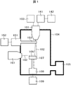
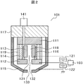
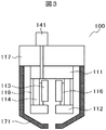
- FIG. 1 is an overall configuration cross-sectional view showing an example of an ion milling apparatus (in accordance with each embodiment of the present invention or provided with a magnetic shield non-ion gun). It is structural sectional drawing for demonstrating the ion gun which does not contain a magnetic shield structure. It is a structural sectional view showing an example (configuration 1, 2) of an ion gun (including a magnetic shield structure) in the ion milling apparatus according to the first embodiment of the present invention.
- FIG. 6 is a structural cross-sectional view showing another example (configuration 3) of an ion gun (including a magnetic shield structure) in the ion milling apparatus according to the first embodiment of the present invention.
- FIG. 6 is a structural cross-sectional view showing another example (configuration 4) of an ion gun (including a magnetic shield structure) in the ion milling apparatus according to the first embodiment of the present invention.
- FIG. 6 is a structural cross-sectional view showing another example (configuration 5) of an ion gun (including a magnetic shield structure) in the ion milling apparatus according to the first embodiment of the present invention.
- FIG. 6 is a structural cross-sectional view showing another example (configuration 6) of an ion gun (including a magnetic shield structure) in the ion milling apparatus according to the first embodiment of the present invention.
- FIG. 6 is a structural cross-sectional view showing another example (configuration 7) of an ion gun (including a magnetic shield structure) in the ion milling apparatus according to the first embodiment of the present invention.
- FIG. 6 is a structural cross-sectional view showing another example (configuration 8) of an ion gun (including a magnetic shield structure) in the ion milling apparatus according to the first embodiment of the present invention.
- It is a figure which shows the magnetic field intensity
- FIG. 5 is a structural cross-sectional view showing an example of an ion gun (including an acceleration electrode guide member) in an ion milling apparatus according to a second embodiment of the present invention.
- FIG. 7 is a structural cross-sectional view showing another example of an ion gun (including an acceleration electrode guide member) in an ion milling apparatus according to a second embodiment of the present invention.
- the inventors examined the above problems and decided to add a magnetic shield to the Penning discharge type ion gun. Thereby, it becomes possible to reduce the leakage magnetic field from the permanent magnet installed in the ion gun.
- a gas supply mechanism that supplies gas into the ion gun, an anode that is disposed inside the ion gun, to which a positive voltage is applied, two cathodes that generate a potential difference between the anode, a cathode ring, An insulator and a permanent magnet are provided, the electrons emitted from the two cathodes are swirled by the magnetic field, the gas is ionized by the swirling electrons, and the generated ions are discharged out of the ion gun by an acceleration electrode.
- the acceleration electrode is formed of a ferromagnetic material.
- a ferromagnetic material can be formed on the surface on which the ion gun-based acceleration electrode is disposed.
- the outer peripheral surface of the acceleration electrode formed of stainless steel and the surface on which the ion gun-based acceleration electrode is disposed can be coated with a ferromagnetic material.
- a ferromagnetic material can be coated on the inner peripheral surface of the acceleration electrode made of stainless steel and the surface on which the ion gun-based acceleration electrode is disposed.
- a magnetic shield structure made of a ferromagnetic material outside the ion gun and to form the ferromagnetic material on the surface on which the ion gun-based acceleration electrode is disposed.
- the cathode ring can be formed of a ferromagnetic material.
- a magnetic shield structure made of a ferromagnetic material can be formed inside the acceleration electrode.
- the ferromagnetic material preferably contains permalloy, pure iron, nickel, copper, molybdenum, and a material mainly composed of at least one of the above.
- the leakage magnetic field from the permanent magnet arranged inside the ion gun can be sufficiently reduced.
- the magnetic shield electrode added to the ion gun it is possible to control the on-axis magnetic field strength inside the ion gun. This makes it possible to select an optimum on-axis magnetic field strength that brings out the ion gun performance, so that a significantly higher milling speed than before can be obtained.
- FIG. 1 is an overall configuration cross-sectional view showing an example of an ion milling apparatus.
- the Penning discharge type ion gun 101 has components necessary for generating ions therein, and forms an irradiation system for irradiating the sample 106 with the ion beam 102.
- the electron microscope column 161 includes components necessary for generating the electron beam 162 therein, and forms an irradiation system for irradiating the sample 106 with the electron beam 162.
- the gas source 142 is connected to the ion gun 101 via the gas supply mechanism 141, and the gas flow rate controlled by the gas supply mechanism 141 is supplied into the ionization chamber of the ion gun 101.
- the irradiation of the ion beam 102 and the ion beam current are controlled by the ion gun control unit 103.
- the ion beam current of the ion beam 102 is measured by the current measuring means 151.
- the current probe 153 also serves as an ion beam shutter, and has a mechanism that is operated by the current probe driver 152.
- the vacuum chamber 104 is controlled to atmospheric pressure or vacuum by a vacuum exhaust system 105.
- the sample 106 is held on a sample table 107, and the sample table 107 is held by a sample table driving unit 108.
- the sample stage drive unit 108 can be pulled out of the vacuum chamber 104 when the vacuum chamber 104 is opened to the atmosphere, and the sample 106 can be inclined at an arbitrary angle with respect to the optical axis of the ion beam 102. Contains all the mechanism elements. Thereby, the sample can be adjusted to a desired direction at the time of processing by the ion beam and at the time of observation by the electron beam.
- the sample stage drive control unit 109 controls the sample stage drive unit 108, can tilt the sample, swing back and forth, and right and left, and can control the speed.
- FIG. 2 is a cross-sectional view showing a configuration of a peripheral portion related to the ion gun 101 not including a magnetic shield structure.
- the ion gun 101 includes a gas supply mechanism 141 that supplies gas into the ion gun, an anode 113, a first cathode 111 and a second cathode 112, a permanent magnet 114, an acceleration electrode 115, an insulator 116, and a cathode ring 119. And fixed to the ion gun base 117.
- the ion gun control unit 103 is electrically connected to the discharge power source 121 and the acceleration power source 122, and controls the discharge voltage and the acceleration voltage.
- Reference numeral 118 denotes an ionization chamber
- reference numeral 131 denotes an anode outlet hole
- reference numeral 132 denotes a cathode outlet hole
- reference numeral 133 denotes an acceleration electrode outlet hole.
- the first cathode 111 and the second cathode 112 are made of ferromagnetic pure iron and form a magnetic circuit together with a permanent magnet 114 which is a magnetomotive force.
- the acceleration electrode 115, the cathode ring 119, and the ion gun base 117 are made of stainless steel (SUS: SteelStSpecial Use Stainless), they are not included in the magnetic circuit together with the alumina insulator 116 and the aluminum anode 113.
- the leakage magnetic field from the ion gun affects the electron beam during observation with an electron microscope.
- a slight electron beam orbit shift is also a problem.
- Electrons emitted from an electron microscope column have the property that their trajectories can be bent by a weak magnetic field. Therefore, in an ion milling device equipped with an electron microscope, the electron beam bends greatly when the acceleration voltage is exchanged. The observation image being observed will be greatly shifted. In order to avoid the shift of the observation image, it is necessary to suppress the leakage magnetic field from the ion gun.
- FIG. 3 is a structural sectional view showing an example of an ion gun (including a magnetic shield structure; hereinafter referred to as a magnetic shield structure ion gun) in the ion milling apparatus according to the present embodiment.
- the ion milling apparatus according to the present embodiment has a configuration in which the ion gun 101 in FIG. 1 is replaced with a magnetic shield structure ion gun 100.
- the Penning discharge type magnetic shield structure ion gun 100 includes a gas supply mechanism 141 that supplies gas to the inside of the ion gun, an anode 113 made of, for example, aluminum that is disposed inside the ion gun and is applied with a positive voltage, and the anode 113.
- a Penning discharge type ion gun including a first cathode 111 and a second cathode 112 made of pure iron, for example, a cathode ring 119 made of stainless steel and an insulator 116 made of, for example, alumina, and a permanent magnet 114 made of, for example, neodymium, which generate a potential difference.
- a magnetic shield 171 made of, for example, Permalloy to the acceleration electrode, a sufficient shielding effect can be obtained, the leakage magnetic field from the magnetic shield structure ion gun 100 can be reduced, and the electron beam 162 emitted from the electron microscope column 161 can be reduced.
- Gauge Shift characterized by sufficiently suppressing (Configuration 1).
- the magnetic shield structure ion gun 100 instead of a permalloy magnetic shield as an accelerating electrode, for example, a magnetic shield effect is obtained by using a magnetic shield 171 made of pure iron, and leakage from the magnetic shield structure ion gun 100 is achieved. It is also possible to reduce the magnetic field and sufficiently suppress the orbital shift of the electron beam 162 emitted from the electron microscope column 161 (Configuration 2).
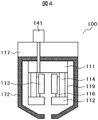
- FIG. 4 is a structural sectional view showing another example of the magnetic shield structure ion gun in the ion milling apparatus according to the present embodiment.
- the acceleration electrode is formed by a magnetic shield 172 made of, for example, pure iron, and in addition to this, for example, the surface of the ion gun base 117 made of, for example, stainless steel is made of, for example, pure iron.
- the magnetic shield 172 it is possible to further reduce the leakage magnetic field from the ion gun 100 having the magnetic shield structure, and to sufficiently suppress the orbital shift of the electron beam 162 emitted from the electron microscope column 161. (Configuration 3).
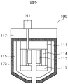
- FIG. 5 is a structural sectional view showing still another example of the magnetic shield structure ion gun in the ion milling apparatus according to the present embodiment.
- This Penning discharge type magnetic shield structure ion gun 100 is made of, for example, magnetism of pure iron on the outer peripheral surface of an acceleration electrode 115 made of, for example, stainless steel and the surface on the side where the acceleration electrode 115 of an ion gun base 117 made of, for example, stainless steel is arranged.
- the shield 173 By covering the shield 173, the leakage magnetic field from the magnetic shield structure ion gun 100 is reduced, and the orbital shift of the electron beam 162 emitted from the electron microscope column 161 is sufficiently suppressed (Configuration 4).
- FIG. 6 is a structural sectional view showing still another example of the magnetic shield structure ion gun in the ion milling apparatus according to the present embodiment.
- This Penning discharge type magnetic shield structure ion gun 100 is made of, for example, pure iron on the inner peripheral surface of an acceleration electrode 115 formed of, for example, stainless steel and the surface on the side where the acceleration electrode 115 of an ion gun base 117 made of, for example, stainless steel is disposed.
- the leakage magnetic field from the ion gun 100 having the magnetic shield structure is reduced, and the orbit shift of the electron beam 162 emitted from the electron microscope column 161 is sufficiently suppressed (Configuration 5). .
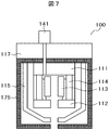
- FIG. 7 is a structural sectional view showing still another example of the magnetic shield structure ion gun in the ion milling apparatus according to the present embodiment.
- the Penning discharge type magnetic shield structure ion gun 100 includes a magnetic shield 175 made of a ferromagnetic material made of pure iron, for example, on the outermost part of the ion gun, and an acceleration electrode made of, for example, stainless steel made of, for example, a stainless steel ion gun base 117.
- a magnetic shield 175 made of pure iron for example, on the surface on which 115 is disposed, the leakage magnetic field from the magnetic shield structure ion gun 100 is reduced, and the orbit shift of the electron beam 162 emitted from the electron microscope column 161 is changed. It is characterized by sufficient suppression (Configuration 6).
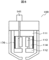
- FIG. 8 is a structural sectional view showing still another example of the magnetic shield structure ion gun in the ion milling apparatus according to the present embodiment.
- the cathode ring is formed by a magnetic shield 176 made of pure iron, for example, so that the leakage magnetic field from the magnetic shield structure ion gun 100 is reduced and emitted from the electron microscope column 161.
- the trajectory shift of the electron beam 162 is sufficiently suppressed (Configuration 7).
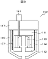
- FIG. 9 is a structural sectional view showing still another example of the magnetic shield structure ion gun in the ion milling apparatus according to the present embodiment.
- This Penning discharge type magnetic shield structure ion gun 100 reduces the leakage magnetic field from the magnetic shield structure ion gun 100 by forming a magnetic shield 177 made of, for example, pure iron inside an acceleration electrode 115 made of stainless steel, for example.
- the trajectory shift of the electron beam 162 emitted from the microscope column 161 is sufficiently suppressed (Configuration 8).
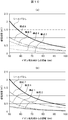
- FIG. 10 is a diagram illustrating the magnetic field strength leaking from the magnetic shield structure ion gun 100 having the above-described configurations in the ion milling apparatus according to the present embodiment.
- FIG. 10A illustrates the configurations 3, 4, 5, 8 and no magnetic shield.
- (b) shows configurations 1, 2, 6, and 7 and the case without a magnetic shield. It is the result of having calculated the leakage magnetic flux density in the magnetic field simulator when the neodymium magnet with a coercive force of 859 kA / m is applied as the permanent magnet 114 mounted in the ion gun with a residual magnetic flux density in the range of 1250 to 1320 mT.
- the leakage magnetic field strength in a region 80 mm away from the tip of the ion gun is 0.69 mT in the ion gun 101 without a magnetic shield, whereas it is 0.12 mT in the magnetic shield structure ion gun of Configuration 1 and 0.09 mT in Configuration 2.
- Configuration 3 can be reduced to 0.03 mT, Configuration 4 to 0.12 mT, Configuration 5 to 0.27 mT, Configuration 6 to 0.12 mT, Configuration 7 to 0.42 mT, Configuration 8 to 0.34 mT. It can be seen that by selecting the structure of the magnetic shield added to the ion gun, the leakage magnetic field strength can be arbitrarily adjusted in the range of 4% to 60% with respect to the ion gun not added with the magnetic shield.
- the Penning discharge type ion gun capable of reducing the magnetic field leakage from the ion gun and sufficiently suppressing the orbit shift of the electron beam emitted from the electron microscope column. Can be provided.
- FIG. 11 is a diagram showing the on-axis magnetic field strength inside the ion gun, where (a) shows configurations 3, 4, 5, 8 and no magnetic shield, and (b) shows configurations 1, 2, 6, 7 and magnetic. The case without shield is shown.
- the magnetic field strength on the central axis of the ion gun when a neodymium magnet having a residual magnetic flux density of 1250 to 1320 mT and a coercive force of 859 kA / m is applied as the permanent magnet 114 mounted in the ion gun is calculated with a magnetic field simulator. is there.
- the on-axis magnetic field strength is about 220 mT in the ion gun 101 without a magnetic shield, whereas it is about 120 mT in the magnetic shield structure ion gun of the configuration 1, about 90 mT in the configuration 2, about 60 mT in the configuration 3, and about 60 mT in the configuration 4.
- 105 mT, configuration 5 is about 100 mT, configuration 6 is about 180 mT, configuration 7 is about 130 mT, and configuration 8 is about 140 mT.
- the on-axis magnetic field strength inside the magnetic shield structure ion gun 100 can be arbitrarily adjusted in the range of 27% to 82% with respect to the ion gun to which no magnetic shield is added. I understand.
- Table 1 shows the performance list of the magnets used.
- FIG. 12 shows the magnetic field strength (magnetic flux) on the central axis of the ion gun when the four types of magnets A to D shown in Table 1 are incorporated as permanent magnets 114 with respect to the ion gun 101 without a magnetic shield.
- (Density) is a result of calculation by a magnetic field simulator.
- the numerical values shown in Table 1 are used for the residual magnetic flux density and the coercive force used in the calculation.
- the position where the magnet is arranged in the Z-axis coordinate which is the horizontal axis in FIG.
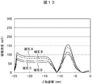
- FIG. 13 shows that the four types of magnets A to D shown in Table 1 are incorporated as permanent magnets 114 in the magnetic shield structure ion gun 100 shown in configuration 2 as an example of this embodiment. It is the result of having calculated the magnetic field intensity (magnetic flux density) on the central axis of the ion gun in the case with a magnetic field simulator.
- the numerical values shown in Table 1 are used for the residual magnetic flux density and the coercive force used in the calculation.
- This region becomes a plasma generation chamber inside the ion gun, and the on-axis magnetic flux density is about 90 mT for magnet A, about 80 mT for magnet B, about 65 mT for magnet C, and about 60 mT for magnet D.
- the on-axis magnetic field strength inside the magnetic shield structure ion gun 100 is reduced by about 41% regardless of the type of magnet compared to the ion gun without the magnetic shield. Thereby, it turns out that the axial magnetic field intensity inside the ion gun can be arbitrarily adjusted within a large range by selecting the magnet type and the magnetic shield structure.
- the amount of ions emitted from the ion gun can be ideally increased by limiting the combination of the appropriate magnetic field strength selection and the appropriate ionization chamber area, depending on the ion gun configuration selected.
- the magnetic shield constitutes a magnetic field control plate that controls the axial magnetic field.
- the processing speed can be controlled in accordance with various uses in which the material or material of the processed sample is different. Note that this effect itself can be obtained without an electron microscope.
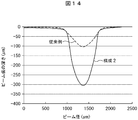
- FIG. 14 is a diagram showing an example of a beam profile for explaining the effect of this embodiment.
- the spot depth in the configuration is shown.
- the conventional example shown in FIG. 14 is an ion gun in which the magnet B shown in Table 1 is incorporated as a permanent magnet 114 in an ion gun 101 to which no magnetic shield is added.
- the anode inner diameter was 4 mm
- the diameter of the anode outlet hole 131 was 4 mm.
- the acceleration voltage was 6 kV
- the discharge voltage was 1.5 kV
- Ar gas having a flow rate of 0.07 cm 3 / min was used as the gas introduced into the ion gun.
- This is a beam profile in the case where milling is performed for 1 hour without using a mask serving as a shielding plate, using silicon as a material to be processed. From the results shown in FIG. 14, the depth of the beam trace is about 100 ⁇ m in the conventional example, whereas in the configuration 2, the depth of the beam trace is about 300 ⁇ m, that is, the milling speed is 300 ⁇ m per hour. In comparison, it is possible to obtain a milling speed about 3 times. Also in this case, the ion beam spot diameter is not reduced.
- an ion milling device capable of suppressing the orbital shift of the electron beam emitted from the electron microscope column by adding the magnetic shield structure to the ion gun. Further, by adding a magnetic shield structure to the ion gun, the axial magnetic field strength inside the ion gun can be controlled to an optimum value. Accordingly, it is possible to provide a Penning discharge type ion milling apparatus capable of obtaining a milling speed that is significantly higher than that of the prior art or obtaining an optimum value of the milling speed according to various materials.
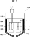
- FIG. 15 is a structural sectional view showing an example of an ion gun (including an acceleration electrode guide) in the ion milling apparatus according to the present embodiment, which is basically the same as the configuration 2 shown in the first embodiment.
- the difference between the ion gun shown in FIG. 15 and the configuration 2 is that the magnetic shield acceleration electrode 180 shown in FIG. 15 has a three-part structure, and an acceleration electrode guide member 181, a first acceleration electrode member 182, and a second acceleration electrode member. 183.
- the acceleration electrode guide member 181 is made of a material other than a ferromagnetic material, for example, stainless steel, and is fixed to the ion gun base 117 by screwing (or fitting).
- the first accelerating electrode member 182 is formed of a ferromagnetic material, for example, pure iron, and is installed by being fitted along the outer periphery of the accelerating electrode guide member 181, and is fixed by the magnetic field of the permanent magnet 114.
- the second acceleration electrode member 183 is formed of a ferromagnetic material, for example, pure iron, and is fitted into a groove formed at the distal end portion of the acceleration electrode guide member 181 and the first acceleration electrode member 182, so that the ion shield 100 is magnetically shielded. It is the structure positioned with respect to it.
- an acceleration electrode guide member 181 made of a material other than a ferromagnetic material is attached without being affected by the permanent magnet 114, and then this acceleration electrode guide member is used as a guide.
- the first and second acceleration electrode members that are magnetic materials can be easily attached. That is, the magnetic shield acceleration electrode 180, which is a ferromagnetic material, can be removed without receiving interference from the permanent magnet 114, and maintainability can be ensured.
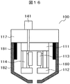
- FIG. 16 is a structural sectional view showing another example of an ion gun (including an acceleration electrode guide) in the ion milling apparatus according to the present embodiment, which is basically the same as the configuration 2 shown in the first embodiment.
- the difference between the ion gun shown in FIG. 16 and Configuration 2 is that the magnetic shield type acceleration electrode 180 shown in FIG. 16 has a two-part structure and includes an acceleration electrode guide member 181 and an acceleration electrode member 182.
- the acceleration electrode guide member 181 is made of a material other than a ferromagnetic material, for example, stainless steel, and is fixed to the ion gun base 117 by screwing.
- the accelerating electrode member 182 is formed of a ferromagnetic material, for example, pure iron, and is installed in a fitting manner along the outer periphery of the accelerating electrode guide member 181, and is fixed by the magnetic field of the permanent magnet 114, so It is a structure that is positioned by. By using this two-divided structure, first, the acceleration electrode guide member 181 made of a material other than the ferromagnetic material is attached without being affected by the permanent magnet 114, and then the acceleration electrode guide member 181 is used as a guide for the magnetic body.
- the acceleration electrode member 182 that is a material can be easily attached. That is, the magnetic shield acceleration electrode 180, which is a ferromagnetic material, can be removed without receiving interference from the permanent magnet 114, and maintainability can be ensured.
- the acceleration electrode guide member is provided, but basically the same effect can be obtained by providing the magnetic shield guide member made of a material other than the ferromagnetic material. Can do.
- a magnetic shield guide member such as an acceleration electrode guide member made of a material other than a ferromagnetic material, it is easy to attach and remove the ferromagnetic magnetic shield, and maintainability can be ensured.
- this invention is not limited to the above-mentioned Example, Various modifications are included.
- the above-described embodiments have been described in detail for easy understanding of the present invention, and are not necessarily limited to those having all the configurations described.
- a part of the configuration of a certain embodiment can be replaced with the configuration of another embodiment, and the configuration of another embodiment can be added to the configuration of a certain embodiment.
- an ion milling apparatus including an ion gun that includes a permanent magnet and generates ions that process a sample, and a scanning electron microscope that observes the sample, A magnetic shield for reducing a leakage magnetic field from the permanent magnet;
- the magnetic shield constitutes a magnetic field control plate for controlling an on-axis magnetic field in the ion gun by changing the structure of the magnetic shield.
- an ion milling apparatus equipped with an ion gun that includes a permanent magnet and generates ions for processing a sample
- An ion milling apparatus wherein a magnetic field control plate is disposed surrounding the outer periphery of the permanent magnet, made of a ferromagnetic material, and controlling an on-axis magnetic field strength of the ion gun.
- the ion gun includes an acceleration electrode that accelerates the ions, and an ion gun base that holds the permanent magnet and the acceleration electrode.
- the ion milling apparatus wherein the magnetic field control plate is also disposed on a surface of the ion gun base on which the acceleration electrode is disposed.
- An ion milling apparatus characterized in that the axial magnetic field intensity inside the ion gun is controlled by changing the structure of the magnetic field control plate.
- SYMBOLS 100 Magnetic-shield structure ion gun, 101 ... Ion gun, 102 ... Ion beam, 103 ... Ion gun control part, 104 ... Vacuum chamber, 105 ... Vacuum exhaust system, 106 ... Sample, 107 ... Sample stand, 108 ... Sample stand drive part, 109 DESCRIPTION OF SYMBOLS ... Sample stage drive control part, 111 ... 1st cathode, 112 ... 2nd cathode, 113 ... Anode, 114 ... Permanent magnet, 115 ... Accelerating electrode, 116 ... Insulator, 117 ... Ion gun base, 118 ... Ionization chamber, 119 ...
Landscapes
- Chemical & Material Sciences (AREA)
- Analytical Chemistry (AREA)
- Physics & Mathematics (AREA)
- Engineering & Computer Science (AREA)
- Plasma & Fusion (AREA)
- Electron Sources, Ion Sources (AREA)
- Drying Of Semiconductors (AREA)
Abstract
Description
前記永久磁石からの漏洩磁場を低減する磁気シールドを有することを特徴とするイオンミリング装置とする。
その際、イオンガンベースの加速電極が配置される面に強磁性体材料を形成することもできる。
また、ステンレスで形成される加速電極の外周面およびイオンガンベースの加速電極が配置される表面に強磁性体材料を被覆することもできる。
また、ステンレスで形成される加速電極の内周面およびイオンガンベースの加速電極が配置される表面に強磁性体材料を被覆することもできる。
また、イオンガン外部に強磁性体材料からなる磁気シールド構造を形成し、かつ、イオンガンベースの加速電極が配置される面に強磁性体材料を形成することもできる。
また、カソードリングを強磁性体材料により形成することもできる。
また、加速電極の内部に強磁性体材料からなる磁気シールド構造を形成することもできる。

(1)永久磁石を含み試料を加工するイオンを発生させるイオンガンと、前記試料を観察する走査電子顕微鏡と、を備えたイオンミリング装置において、
前記永久磁石からの漏洩磁場を低減する磁気シールドを有し、
前記磁気シールドは、前記磁気シールドの構造の変更により前記イオンガンにおける軸上磁場を制御する磁場制御板を構成するものであることを特徴とするイオンミリング装置。
(2)永久磁石を含み試料を加工するイオンを発生させるイオンガンを備えたイオンミリング装置において、
前記永久磁石の外周を取り囲んで配置され、強磁性材料からなり、前記イオンガンの軸上磁場強度を制御する磁場制御板が配置されていることを特徴とするイオンミリング装置。
(3)上記(2)に記載のイオンミリング装置において、
前記イオンガンは、前記イオンを加速する加速電極と、前記永久磁石と前記加速電極とを保持するイオンガンベースとを備え、
前記磁場制御板は、前記イオンガンベースの前記加速電極が配置される側の表面にも配置されていることを特徴とするイオンミリング装置。
(4)上記(2)に記載のイオンミリング装置において、
前記イオンガン内部の軸上磁場強度は、前記磁場制御板の構造の変更により制御されることを特徴とするイオンミリング装置。
Claims (15)
- 永久磁石を含み試料を加工するイオンを発生させるイオンガンと、前記試料を観察する走査電子顕微鏡と、を備えたイオンミリング装置において、
前記永久磁石からの漏洩磁場を低減する磁気シールドを有することを特徴とするイオンミリング装置。 - 請求項1に記載のイオンミリング装置において、
前記イオンガンは、前記イオンを加速する加速電極を備え、
前記磁気シールドは、前記加速電極を強磁性体材料で構成したものであることを特徴とするイオンミリング装置。 - 請求項2に記載のイオンミリング装置において、
前記イオンガンは、前記永久磁石と前記加速電極とを保持するイオンガンベースを備え、
前記イオンガンベースの前記加速電極が配置される側の表面に強磁性体材料が配置されていることを特徴とするイオンミリング装置。 - 請求項1に記載のイオンミリング装置において、
前記イオンガンは、前記イオンを加速する加速電極と、前記永久磁石と前記加速電極とを保持するイオンガンベースとを備え、
前記磁気シールドは、前記加速電極の外周面および前記イオンガンベースの前記加速電極が配置される側の表面に被覆された強磁性体材料で構成されていることを特徴とするイオンミリング装置。 - 請求項1に記載のイオンミリング装置において、
前記イオンガンは、前記イオンを加速する加速電極と、前記永久磁石と前記加速電極とを保持するイオンガンベースとを備え、
前記磁気シールドは、前記加速電極の内周面および前記イオンガンベースの前記加速電極が配置される側の表面に被覆された強磁性体材料で構成されていることを特徴とするイオンミリング装置。 - 請求項1に記載のイオンミリング装置において、
前記イオンガンは、前記イオンを加速する加速電極と、前記永久磁石と前記加速電極とを保持するイオンガンベースとを備え、
前記磁気シールドは、前記イオンガンベースの前記加速電極が配置される側の表面に配置された強磁性体材料と、前記加速電極を覆い前記加速電極とは離間して配置された強磁性体材料とで構成されていることを特徴とするイオンミリング装置。 - 請求項1に記載のイオンミリング装置において、
前記イオンガンは、前記永久磁石の外周面に配置されたカソードリングを備え、
前記磁気シールドは、前記カソードリングを強磁性体材料で構成したものであることを特徴とするイオンミリング装置。 - 請求項1に記載のイオンミリング装置において、
前記磁気シールドは、前記永久磁石の外周を取り囲み前記永久磁石とは離間して配置された強磁性体材料で構成されていることを特徴とするイオンミリング装置。 - 請求項1に記載のイオンミリング装置において、
前記磁気シールドは、パーマロイ、純鉄、ニッケル、銅、モリブデン、および前記の少なくとも一種を主成分とする材料で構成されていることを特徴とするイオンミリング装置。 - 請求項2に記載のイオンミリング装置において、
前記イオンガンは、前記永久磁石と前記加速電極とを保持するイオンガンベースを備え、
前記加速電極は、加速電極ガイド部材、第一の加速電極部材、第二の加速電極部材の3分割構造であり、
前記加速電極ガイド部材は、強磁性体以外の材料で形成され前記イオンガンベースに固定され、
前記第一の加速電極部材は、強磁性体で形成され前記加速電極ガイド部材の外側に設置され、
前記第二の加速電極部材は、強磁性体で形成され前記加速電極ガイド部材と前記第一の加速電極部材にて位置決めされて設置され、
前記第一および前記第二の加速電極部材は前記永久磁石の磁場により固定されていることを特徴とするイオンミリング装置。 - 請求項1に記載のイオンミリング装置において、
前記磁気シールドは、前記永久磁石の外側を取り囲んで配置され、強磁性体以外の材料からなる磁気シールドガイド部材と、前記磁気シールドガイド部材の外側を取り囲んで配置され強磁性体材料からなる磁気シールド部材とを有することを特徴とするイオンミリング装置。 - 永久磁石を含み試料を加工するイオンを発生させるイオンガンと、前記試料を観察する走査電子顕微鏡と、を備えたイオンミリング装置において、
前記永久磁石からの漏洩磁場を低減する磁気シールドを有し、
前記磁気シールドは、前記磁気シールドの構造の変更により前記イオンガンにおける軸上磁場を制御する磁場制御板を構成するものであることを特徴とするイオンミリング装置。 - 永久磁石を含み試料を加工するイオンを発生させるイオンガンを備えたイオンミリング装置において、
前記永久磁石の外周を取り囲んで配置され、強磁性材料からなり、前記イオンガンの軸上磁場強度を制御する磁場制御板が配置されていることを特徴とするイオンミリング装置。 - 請求項13に記載のイオンミリング装置において、
前記イオンガンは、前記イオンを加速する加速電極と、前記永久磁石と前記加速電極とを保持するイオンガンベースとを備え、
前記磁場制御板は、前記イオンガンベースの前記加速電極が配置される側の表面にも配置されていることを特徴とするイオンミリング装置。 - 請求項13に記載のイオンミリング装置において、
前記イオンガン内部の軸上磁場強度は、前記磁場制御板の構造の変更により制御されることを特徴とするイオンミリング装置。
Priority Applications (5)
| Application Number | Priority Date | Filing Date | Title |
|---|---|---|---|
| US15/760,994 US10361065B2 (en) | 2015-09-25 | 2015-09-25 | Ion milling system |
| JP2017541208A JP6637055B2 (ja) | 2015-09-25 | 2015-09-25 | イオンミリング装置 |
| DE112015006787.6T DE112015006787B4 (de) | 2015-09-25 | 2015-09-25 | Ionenätzsystem |
| PCT/JP2015/077095 WO2017051469A1 (ja) | 2015-09-25 | 2015-09-25 | イオンミリング装置 |
| CN201580082721.4A CN107949899B (zh) | 2015-09-25 | 2015-09-25 | 离子铣削装置 |
Applications Claiming Priority (1)
| Application Number | Priority Date | Filing Date | Title |
|---|---|---|---|
| PCT/JP2015/077095 WO2017051469A1 (ja) | 2015-09-25 | 2015-09-25 | イオンミリング装置 |
Publications (1)
| Publication Number | Publication Date |
|---|---|
| WO2017051469A1 true WO2017051469A1 (ja) | 2017-03-30 |
Family
ID=58385912
Family Applications (1)
| Application Number | Title | Priority Date | Filing Date |
|---|---|---|---|
| PCT/JP2015/077095 Ceased WO2017051469A1 (ja) | 2015-09-25 | 2015-09-25 | イオンミリング装置 |
Country Status (5)
| Country | Link |
|---|---|
| US (1) | US10361065B2 (ja) |
| JP (1) | JP6637055B2 (ja) |
| CN (1) | CN107949899B (ja) |
| DE (1) | DE112015006787B4 (ja) |
| WO (1) | WO2017051469A1 (ja) |
Cited By (2)
| Publication number | Priority date | Publication date | Assignee | Title |
|---|---|---|---|---|
| WO2021038754A1 (ja) * | 2019-08-28 | 2021-03-04 | 株式会社日立ハイテク | イオンガン及びイオンミリング装置 |
| CN116261767A (zh) * | 2020-09-17 | 2023-06-13 | 卡尔蔡司Smt有限责任公司 | 以粒子束分析和/或处理样品的装置及方法 |
Families Citing this family (4)
| Publication number | Priority date | Publication date | Assignee | Title |
|---|---|---|---|---|
| WO2019167165A1 (ja) * | 2018-02-28 | 2019-09-06 | 株式会社日立ハイテクノロジーズ | イオンミリング装置及びイオンミリング装置のイオン源調整方法 |
| CN108878249B (zh) * | 2018-06-19 | 2020-01-17 | 大连理工大学 | 一种脉冲潘宁放电等离子体发生装置 |
| CN110449645B (zh) * | 2019-07-26 | 2020-06-16 | 武汉数字化设计与制造创新中心有限公司 | 一种提高fibm三维微结构面形精度的方法 |
| KR102858714B1 (ko) | 2024-05-14 | 2025-09-10 | 서울대학교산학협력단 | 플라즈마 디바이스 |
Citations (4)
| Publication number | Priority date | Publication date | Assignee | Title |
|---|---|---|---|---|
| US4800281A (en) * | 1984-09-24 | 1989-01-24 | Hughes Aircraft Company | Compact penning-discharge plasma source |
| JP2002208374A (ja) * | 2001-01-11 | 2002-07-26 | Seiko Instruments Inc | 集束イオンビーム装置 |
| JP2013011540A (ja) * | 2011-06-30 | 2013-01-17 | Hitachi High-Technologies Corp | 試料の作製装置,作製方法、及びそれを用いた荷電粒子線装置 |
| JP2014235948A (ja) * | 2013-06-04 | 2014-12-15 | 株式会社日立ハイテクノロジーズ | イオン源およびイオンミリング装置 |
Family Cites Families (9)
| Publication number | Priority date | Publication date | Assignee | Title |
|---|---|---|---|---|
| JPH08298092A (ja) | 1995-04-26 | 1996-11-12 | Hitachi Ltd | 走査電子顕微鏡の分析方法 |
| JP2000195460A (ja) | 1998-12-28 | 2000-07-14 | Canon Inc | 走査電子顕微鏡による分析方法 |
| JP2003342757A (ja) * | 2002-05-28 | 2003-12-03 | Canon Inc | ミリング方法およびミリング装置 |
| JP5194133B2 (ja) * | 2009-01-15 | 2013-05-08 | 株式会社日立ハイテクノロジーズ | イオンビーム装置 |
| JP2011154920A (ja) * | 2010-01-28 | 2011-08-11 | Hitachi High-Technologies Corp | イオンミリング装置,試料加工方法,加工装置、および試料駆動機構 |
| WO2012060416A1 (ja) | 2010-11-05 | 2012-05-10 | 株式会社 日立ハイテクノロジーズ | イオンミリング装置 |
| JP5480110B2 (ja) * | 2010-11-22 | 2014-04-23 | 株式会社日立ハイテクノロジーズ | イオンミリング装置及びイオンミリング加工方法 |
| EP2690648B1 (en) | 2012-07-26 | 2014-10-15 | Fei Company | Method of preparing and imaging a lamella in a particle-optical apparatus |
| JP6180952B2 (ja) * | 2014-01-31 | 2017-08-16 | 東芝メモリ株式会社 | デバイス製造装置及び磁気デバイスの製造方法 |
-
2015
- 2015-09-25 WO PCT/JP2015/077095 patent/WO2017051469A1/ja not_active Ceased
- 2015-09-25 JP JP2017541208A patent/JP6637055B2/ja active Active
- 2015-09-25 CN CN201580082721.4A patent/CN107949899B/zh active Active
- 2015-09-25 US US15/760,994 patent/US10361065B2/en active Active
- 2015-09-25 DE DE112015006787.6T patent/DE112015006787B4/de active Active
Patent Citations (4)
| Publication number | Priority date | Publication date | Assignee | Title |
|---|---|---|---|---|
| US4800281A (en) * | 1984-09-24 | 1989-01-24 | Hughes Aircraft Company | Compact penning-discharge plasma source |
| JP2002208374A (ja) * | 2001-01-11 | 2002-07-26 | Seiko Instruments Inc | 集束イオンビーム装置 |
| JP2013011540A (ja) * | 2011-06-30 | 2013-01-17 | Hitachi High-Technologies Corp | 試料の作製装置,作製方法、及びそれを用いた荷電粒子線装置 |
| JP2014235948A (ja) * | 2013-06-04 | 2014-12-15 | 株式会社日立ハイテクノロジーズ | イオン源およびイオンミリング装置 |
Cited By (7)
| Publication number | Priority date | Publication date | Assignee | Title |
|---|---|---|---|---|
| WO2021038754A1 (ja) * | 2019-08-28 | 2021-03-04 | 株式会社日立ハイテク | イオンガン及びイオンミリング装置 |
| JPWO2021038754A1 (ja) * | 2019-08-28 | 2021-03-04 | ||
| KR20220019827A (ko) * | 2019-08-28 | 2022-02-17 | 주식회사 히타치하이테크 | 이온건 및 이온 밀링 장치 |
| JP7186884B2 (ja) | 2019-08-28 | 2022-12-09 | 株式会社日立ハイテク | イオンガン及びイオンミリング装置 |
| US12051560B2 (en) | 2019-08-28 | 2024-07-30 | Hitachi High-Tech Corporation | Ion gun and ion milling machine |
| KR102755862B1 (ko) | 2019-08-28 | 2025-01-21 | 주식회사 히타치하이테크 | 이온건 및 이온 밀링 장치 |
| CN116261767A (zh) * | 2020-09-17 | 2023-06-13 | 卡尔蔡司Smt有限责任公司 | 以粒子束分析和/或处理样品的装置及方法 |
Also Published As
| Publication number | Publication date |
|---|---|
| DE112015006787T5 (de) | 2018-04-26 |
| JPWO2017051469A1 (ja) | 2018-07-05 |
| CN107949899A (zh) | 2018-04-20 |
| JP6637055B2 (ja) | 2020-01-29 |
| US20180286633A1 (en) | 2018-10-04 |
| CN107949899B (zh) | 2019-11-15 |
| US10361065B2 (en) | 2019-07-23 |
| DE112015006787B4 (de) | 2021-11-25 |
Similar Documents
| Publication | Publication Date | Title |
|---|---|---|
| JP6637055B2 (ja) | イオンミリング装置 | |
| JP6220749B2 (ja) | イオンガン及びイオンミリング装置、イオンミリング方法 | |
| US7965818B2 (en) | Field emission X-ray apparatus, methods, and systems | |
| CN110176379B (zh) | 带电粒子束装置和试样加工观察方法 | |
| CN110431649B (zh) | 带电粒子束装置 | |
| JPWO2018011946A1 (ja) | イオンミリング装置 | |
| JP6100619B2 (ja) | イオン源およびイオンミリング装置 | |
| JP2020509548A (ja) | イオン源デバイス | |
| US11412607B2 (en) | Atomic beam generator, bonding apparatus, surface modification method, and bonding method | |
| JP7186884B2 (ja) | イオンガン及びイオンミリング装置 | |
| EP2355125A2 (en) | Particle beam device and method for operation of a particle beam device | |
| JP2016134295A (ja) | 多極子レンズおよび荷電粒子ビーム装置 | |
| CN105898976A (zh) | 等离子体离子源以及带电粒子束装置 | |
| JP2018022701A (ja) | イオンガン及びイオンミリング装置、イオンミリング方法 | |
| TW202129686A (zh) | 離子研磨裝置 | |
| JP2012142129A (ja) | 軟x線源 | |
| JP2018170295A (ja) | イオンガン及びイオンミリング装置、イオンミリング方法 | |
| JP2017174504A (ja) | 複合荷電粒子ビーム装置 | |
| WO2017134817A1 (ja) | 電界電離イオン源、イオンビーム装置、およびビーム照射方法 | |
| US20250308834A1 (en) | Ion milling device and ion milling method | |
| JP2004362937A (ja) | イオン源 | |
| JP2026009617A (ja) | イオン源及びイオン源利用システム | |
| JPH11297248A (ja) | 電子線加速装置 | |
| WO2022244149A1 (ja) | イオンミリング装置 | |
| JPS60180050A (ja) | イオン照射装置 |
Legal Events
| Date | Code | Title | Description |
|---|---|---|---|
| 121 | Ep: the epo has been informed by wipo that ep was designated in this application |
Ref document number: 15904726 Country of ref document: EP Kind code of ref document: A1 |
|
| WWE | Wipo information: entry into national phase |
Ref document number: 112015006787 Country of ref document: DE |
|
| ENP | Entry into the national phase |
Ref document number: 2017541208 Country of ref document: JP Kind code of ref document: A |
|
| WWE | Wipo information: entry into national phase |
Ref document number: 15760994 Country of ref document: US |
|
| 122 | Ep: pct application non-entry in european phase |
Ref document number: 15904726 Country of ref document: EP Kind code of ref document: A1 |