WO2017030036A1 - 内視鏡 - Google Patents
内視鏡 Download PDFInfo
- Publication number
- WO2017030036A1 WO2017030036A1 PCT/JP2016/073309 JP2016073309W WO2017030036A1 WO 2017030036 A1 WO2017030036 A1 WO 2017030036A1 JP 2016073309 W JP2016073309 W JP 2016073309W WO 2017030036 A1 WO2017030036 A1 WO 2017030036A1
- Authority
- WO
- WIPO (PCT)
- Prior art keywords
- grip
- inclined surface
- finger
- longitudinal axis
- user
- Prior art date
Links
Images


Classifications
-
- A—HUMAN NECESSITIES
- A61—MEDICAL OR VETERINARY SCIENCE; HYGIENE
- A61B—DIAGNOSIS; SURGERY; IDENTIFICATION
- A61B1/00—Instruments for performing medical examinations of the interior of cavities or tubes of the body by visual or photographical inspection, e.g. endoscopes; Illuminating arrangements therefor
- A61B1/005—Flexible endoscopes
- A61B1/0051—Flexible endoscopes with controlled bending of insertion part
- A61B1/0052—Constructional details of control elements, e.g. handles
-
- A—HUMAN NECESSITIES
- A61—MEDICAL OR VETERINARY SCIENCE; HYGIENE
- A61B—DIAGNOSIS; SURGERY; IDENTIFICATION
- A61B1/00—Instruments for performing medical examinations of the interior of cavities or tubes of the body by visual or photographical inspection, e.g. endoscopes; Illuminating arrangements therefor
- A61B1/00064—Constructional details of the endoscope body
- A61B1/00066—Proximal part of endoscope body, e.g. handles
-
- A—HUMAN NECESSITIES
- A61—MEDICAL OR VETERINARY SCIENCE; HYGIENE
- A61B—DIAGNOSIS; SURGERY; IDENTIFICATION
- A61B1/00—Instruments for performing medical examinations of the interior of cavities or tubes of the body by visual or photographical inspection, e.g. endoscopes; Illuminating arrangements therefor
- A61B1/005—Flexible endoscopes
- A61B1/0051—Flexible endoscopes with controlled bending of insertion part
- A61B1/0055—Constructional details of insertion parts, e.g. vertebral elements
-
- G—PHYSICS
- G02—OPTICS
- G02B—OPTICAL ELEMENTS, SYSTEMS OR APPARATUS
- G02B23/00—Telescopes, e.g. binoculars; Periscopes; Instruments for viewing the inside of hollow bodies; Viewfinders; Optical aiming or sighting devices
- G02B23/24—Instruments or systems for viewing the inside of hollow bodies, e.g. fibrescopes
-
- A—HUMAN NECESSITIES
- A61—MEDICAL OR VETERINARY SCIENCE; HYGIENE
- A61B—DIAGNOSIS; SURGERY; IDENTIFICATION
- A61B1/00—Instruments for performing medical examinations of the interior of cavities or tubes of the body by visual or photographical inspection, e.g. endoscopes; Illuminating arrangements therefor
- A61B1/00131—Accessories for endoscopes
Definitions
- the present invention relates to an endoscope that is used by a user holding it by hand.
- the outer shell of the grip portion of the endoscope operation assembly disclosed in Japanese Patent Application Laid-Open No. 2007-222651 is formed in a cylindrical shape.
- Two adjacent surfaces of the outer shell of the grip portion are arranged at approximately 90 °.
- the corners between these two adjacent surfaces are continuously formed as curved surfaces.
- a ridge is formed on the surface of the outer shell of the grip portion on the side where the bending operation knob is provided along the longitudinal direction of the grip portion.
- an endoscope is configured such that a lower surface of a universal cord is disposed between a thumb and an index finger of a user's left hand to grip a grip portion of an operation assembly. Then, the user may hold the endoscope insertion part firmly with the right hand and move the right hand appropriately to twist the insertion part while holding the gripping part of the operation assembly properly with the left hand. . In this case, in order to counter the reaction force from the insertion portion against twisting, the user needs to move the operation portion appropriately in conjunction with the movement of the insertion portion while firmly grasping the grip portion. When a user with a relatively small hand appropriately grasps the grasping portion of the endoscope disclosed in Japanese Patent Application Laid-Open No.
- the finger pad of a ring finger or little finger may hit a curved surface at the corner of the two surfaces. .
- the finger pad since the contact area between the user's finger pad and the curved surface is small, the finger pad easily slips with respect to the curved surface of the grip part, and it may be difficult to stably grip the grip part.
- gripping when the finger pad becomes slippery with respect to the curved surface, gripping may not be stable, and the surface of the two adjacent surfaces facing the universal cord may be gripped. The gripping force that is applied is more likely to go in the direction toward the universal cord than in the user's palm.
- a ridge may hit the finger pad of a ring finger or a little finger, for example. In this case, the contact area between the finger pad and the ridge is small. It may be difficult to keep gripping.
- An object of the present invention is to provide an endoscope that can easily hold a gripping part stably even if the user has a relatively large hand or a small user.
- An endoscope includes an insertion portion that is inserted into a subject and has a bending portion that can be bent, a longitudinal axis is defined, and the bending portion of the insertion portion is remotely operated
- An operation portion provided with a bending operation knob, and a cylindrical holding portion provided between the insertion portion and the operation portion and held by a user on the side where the bending operation knob is provided
- the first inclined surface that is inclined with respect to the first surface and the protruding portion provided on the opposite side of the protruding portion from the first inclined surface with the ridge interposed therebetween And the side surface, and a grip portion having a flat or concave second inclined surface inclined with respect to the first surface and the side surface.
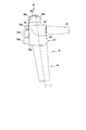
- FIG. 1A is a schematic perspective view showing an endoscope according to the first and second embodiments.
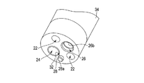
- FIG. 1B is a schematic perspective view showing the distal end hard portion of the insertion portion of the endoscope according to the first and second embodiments.
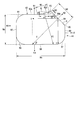
- FIG. 2 is a schematic cross-sectional view taken along the line II-II in FIG. 1A of the endoscope operation assembly according to the first embodiment.
- FIG. 3 is a schematic diagram showing the gripping part in FIG. 2 of the operation assembly of the endoscope according to the first embodiment.
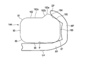
- FIG. 4 is a schematic diagram showing a state in which the user has a relatively small hand holding the operation assembly of the endoscope according to the first embodiment.
- FIG. 5A is a schematic diagram illustrating a state in which a user with a relatively small hand grips the grip portion of the operation assembly of the endoscope according to the first embodiment.
- FIG. 5B is a schematic diagram illustrating a state in which a user with a relatively small hand grips a gripping portion as a reference example for comparison with the gripping portion of the operation assembly of the endoscope according to the first embodiment.
- FIG. 6 is a schematic diagram illustrating a state where the user has a relatively large hand holding the endoscope operation assembly according to the first embodiment.
- FIG. 7A is a schematic diagram showing a state in which a user with a relatively large hand grips the grip portion of the operation assembly of the endoscope according to the first embodiment.
- FIG. 7B is a schematic diagram illustrating a state in which a user with a relatively large hand grips a gripping portion as a reference example for comparison with the gripping portion of the operation assembly of the endoscope according to the first embodiment.
- FIG. 8 is a schematic diagram showing the gripping part in FIG. 2 of the operation assembly of the endoscope according to the second embodiment.
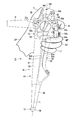
- FIG. 9A is a schematic top view showing a state in which the user holds the operation assembly of the endoscope according to the first reference embodiment with the left hand.
- FIG. 9B is a schematic diagram illustrating a state in which the operation assembly of the endoscope according to the first reference embodiment is viewed from the side opposite to the knob arrangement surface.
- FIG. 10A is a schematic diagram illustrating a state in which the operation assembly of the endoscope according to the second reference embodiment is viewed from the opposite side of the knob arrangement surface when the user holds the operation assembly with the left hand.
- FIG. 10B is a schematic top view showing the operation assembly of the endoscope according to the second reference embodiment.
- an endoscope 10 includes an insertion portion 12 to be inserted into a subject, an operation assembly 14 provided at a proximal end portion of the insertion portion 12, and an operation assembly 14. And a universal cord 16 connected to an external device such as a control device of the endoscope 10.
- the universal cord 16 connects the operation assembly 14 to an external device (not shown) such as a monitor or a control device.
- the virtual longitudinal axis L is prescribed
- the virtual longitudinal axis L is defined not only on the insertion portion 12 but also on the operation assembly 14 as being coaxial.
- the endoscope 10 includes an illumination optical system 22, an observation optical system 24, a treatment instrument insertion channel 26, and an air / water supply path 28, which are well-known.
- the illumination optical system 22 and the observation optical system 24 are disposed from the distal end portion of the insertion portion 12 of the endoscope 10 through the operation assembly 14 to a connector (not shown) of the universal cord 16.
- the treatment instrument insertion channel 26 has a proximal end opening 26a serving as an inlet of the treatment instrument in a grip section 44 described later of the operation assembly 14, and serves as an outlet of the treatment instrument in a distal end hard section 32 described later of the insertion section 12. It has a tip opening 26b.
- the tip opening 26b of the channel 26 also functions as the tip opening of the suction path.
- the proximal end of the suction path is disposed on a connector (not shown) of the universal cord 16 through the operation assembly 14.
- the channel 26 can suck biological tissue, physiological saline, and the like from the distal end opening 26b of the channel 26 at the distal end of the distal end hard portion 32 by a pressing operation of a suction button 54a described later.
- air / water supply path 28 for example, air is discharged from the nozzle 28 a disposed at the tip of the distal end hard portion 32 by an operation for closing a hole of an air / water supply button 54 b described later of the operation assembly 14.
- physiological saline is discharged from the nozzle 28a by the pressing operation of the water supply button 54b.
- the insertion portion 12 includes a distal end hard portion 32, a bending portion 34, and a flexible tube portion 36 in order from the distal end to the proximal end.
- the proximal end of the insertion portion 12, that is, the proximal end of the flexible tube portion 36 is connected to the operation assembly 14.
- the operation assembly 14 includes an operation unit 42 in which various mechanisms to be operated are disposed, a grip 44 (grip) 44 that is gripped by the user, and an insertion unit 12. And a bend stopper 46 for preventing buckling.
- the operation assembly 14 is arranged along the longitudinal axis L in the order of the folding stop 46, the gripping portion 44, and the operation portion 42 in this order from the side close to the insertion portion 12 toward the side away from the insertion portion 12.
- the base end of the flexible tube portion 36 is connected to the bend stopper 46 via a base (not shown).
- the bending operation knobs 52a and 52b On the outer peripheral surface of the operation unit 42, as a part of various mechanisms to be operated, the bending operation knobs 52a and 52b, the suction button (fluid control button) 54a, the air / water supply button (fluid control button) 54b, and the first To fourth switches 56a, 56b, 56c, and 56d.
- the knob disposing surface 62 on which the bending operation knobs 52 a and 52 b are disposed As the outer peripheral surface of the operation unit 42, along the circumferential direction around the longitudinal axis L, the knob disposing surface 62 on which the bending operation knobs 52 a and 52 b are disposed, the suction button 54 a, the air / water supply button 54 b, The button arrangement surface 64 on which the first and second switches 56a and 56b are arranged, and the support portion 66 that is extended between the base of the thumb T of the user's left hand LH and the base of the index finger IF. And a user facing surface (switch disposing surface) 68 on which the fourth switch 56d is disposed.
- the operation unit 42 is provided with a third switch 56c at the upper end thereof. Note that appropriate functions are set for the first to fourth switches 56a, 56b, 56c, and 56d, respectively.
- the support part 66 is mounted on the index finger IF of the user's left hand LH in a state where the user facing surface 68 is arranged so as to face the user.
- the support portion 66 is supported at a position between the base of the thumb T and the base of the index finger IF of the user's hand LH to the back of the hand.
- the lower surface of the universal cord 16 is supported near the base of the thumb T. That is, the universal cord 16 is supported at a position from between the base of the thumb T of the user's hand and the base of the index finger IF to the back of the hand. Then, the user places the thumb T of the left hand LH on the operation unit 42 or the knobs 52a and 52b through the lower side of the universal cord 16.
- the bending operation knobs 52a and 52b can remotely operate the bending portion 34 of the insertion portion 12.
- the bending portion 34 can be bent in the U direction and the D direction by rotating the bending operation knob 52a.
- the bending portion 34 can be bent in the R direction and the L direction by rotating the bending operation knob 52b. Note that the rotation axes of the bending operation knobs 52a and 52b are substantially orthogonal to the longitudinal axis L.
- a step 64 a is formed between the knob disposition surface 62, the button disposition surface 64 and the support portion 66 of the operation portion 42, and second and third grip surfaces 82 and 84 described later of the grip portion 44.
- the grip portion 44 is formed in a cylindrical shape and has a base end opening 26 a of the channel 26.
- the base end opening 26 a of the channel is disposed at a position close to the folding stop 46 in the grip 44 between the operation unit 42 and the folding stop 46.
- FIG. 2 shows the outer shell shape of the grip portion 44 along the line II-II in FIG. 1A. That is, in FIG. 2, the operation assembly 14 is viewed from the grip portion 44 side toward the operation portion 42 side.
- the illumination optical system 22, the observation optical system 24, the air / water supply path 28, and the mechanism used for the bending of the bending portion 34 are disposed inside the grip portion 44.
- the illustration of the object is omitted.
- the illustration of the built-in object is also omitted in FIGS. 3 to 8.
- FIG. 3 schematically shows the outer shell shape of the grip portion 44 shown in FIG.
- the grip portion 44 has a first grip surface (knob side grip surface) 82, a second grip surface 84, and a third grip in the circumferential direction around the longitudinal axis L as the outer peripheral surface.
- the grip portion 44 has an outer peripheral surface in the circumferential direction with respect to the longitudinal axis L formed in an annular shape by the cooperation of the first to fifth grip surfaces 82, 84, 86, 88, 90. For this reason, the grip part 44 is formed in a cylindrical shape in cooperation with the first to fifth grip surfaces 82, 84, 86, 88, 90, and is gripped by the user. Note that the gripping portion 44 is provided between the insertion portion 12 and the operation portion 42 along the longitudinal axis L.
- the third grip surface 86 is formed as a side surface disposed between the first grip surface 82 and the fourth grip surface 88. It is preferable that a part of the first grip surface 82 (a flat surface portion 82a to be described later) and the third grip surface 86 are arranged at approximately 90 ° with respect to each other via the second grip surface 84. It is preferable that the fourth grip surfaces 88 adjacent to the third grip surface 86 are arranged at approximately 90 ° with respect to each other. The fifth grip surfaces 90 adjacent to the fourth grip surface 88 are preferably arranged at approximately 90 ° with respect to each other. It is preferable that a part of the first grip surface 82 adjacent to the fifth grip surface 90 (the flat surface portion 82a) is disposed at approximately 90 °.
- the first grip surface 82 is defined as a “first surface (reference surface)”, and the fourth grip surface 88 is defined as a “second surface”.
- the fourth grip surface 88 which is defined as “second surface”, is formed on the back side of the first grip surface (first surface) 82 with respect to the longitudinal axis L. It is preferable that the first grip surface 82 and the fourth grip surface 88 have portions parallel to each other. For this reason, it is preferable that the normal line N1 of the first grip surface 82 and the normal line N4 of the fourth grip surface 88 are oriented in substantially opposite directions. It is preferable that the third grip surface 86 and the fifth grip surface 90 have portions parallel to each other.
- the normal line N3 of the third grip surface 86 and the normal line N5 of the fifth grip surface 90 are oriented in substantially opposite directions.
- the second grip surface 84 has inclined surfaces (regular surfaces in a gripping force load direction F1 described later) 84a that are inclined with respect to the first grip surface 82 and the third to fifth grip surfaces 86, 88, 90, respectively. Therefore, the normal line N2 of the second grip surface 84 is inclined with respect to the normal lines N1, N3, N4, and N5 of the first grip surface 82 and the third to fifth grip surfaces 86, 88, and 90, respectively. Yes.
- the Y-axis is parallel to the normal lines N1 and N4 in the plane regions of the first grip surface 82 and the fourth grip surface 88, and in the plane region of the third grip surface 86 and the fifth grip surface 90.
- the X axis is taken parallel to the normal lines N3 and N5.
- the width (length) of the fourth grip surface 88 in the X-axis direction is Wa
- the width (length) of the fifth grip surface 90 in the Y-axis direction is Wb.
- the width Wa is preferably larger than the width Wb at a position closer to the operation portion 42 than the folding stop 46 shown in FIG.
- the width Wa and Wb may be substantially the same in the position close to the folding stop 46 shown in FIG.
- the first grip surface 82 of the grip portion 44 is adjacent to the knob arrangement surface 62 of the operation portion 42 along the longitudinal axis L.
- the second grip surface 84 of the grip portion 44 is adjacent to the knob disposition surface 62 and the step 64a of the operation portion 42 along the longitudinal axis L.
- the third grip surface 86 of the grip portion 44 is adjacent to the step 64 a of the operation portion 42 along the longitudinal axis L.
- the fourth grip surface 88 of the grip portion 44 is adjacent to the support portion 66 of the operation portion 42 along the longitudinal axis L.
- the fifth grip surface 90 of the grip portion 44 is adjacent to the user facing surface 68 of the operation portion 42 along the longitudinal axis L.
- the boundary between the user facing surface 68 of the operation unit 42 and the fifth grip surface 90 of the grasping unit 44 is preferably formed so that both are continuous without a step, such as a substantially planar shape.
- the first grip surface 82 is provided with knobs 52 a and 52 b in positions adjacent to the first grip surface 82 around the longitudinal axis L (the first grip surface 82.
- the protrusion 83 is provided so as to protrude in the direction in which the normal line N1 extends.
- the protruding portion 83 that protrudes outward in the radial direction of the longitudinal axis L with respect to the first grip surface 82 continuously forms a peak (ridge) in the axial direction of the longitudinal axis L.
- a ridge 83a is formed.
- the ridge 83a and the inclined surface 84a of the protrusion 83 are adjacent to each other in the circumferential direction of the longitudinal axis L.
- the ridge 83a is preferably formed as a curved surface with an appropriate width such as several millimeters along the circumferential direction of the longitudinal axis L.
- the ridge 83a has a vertex portion in which the radius R is set to, for example, 1 mm to 5 mm in the circumferential direction (width direction).
- the ridge 83 a is formed from the upper end to the lower end of the grip portion 44.
- the ridge 83a does not need to be formed from the upper end to the lower end of the grip portion 44, and may be formed, for example, at a portion where the ring finger RF or the little finger LF hits.
- the first grip surface 82 includes a substantially flat flat surface portion (first surface) 82a and an inclined surface (first inclined surface) 82b formed between the flat surface portion 82a and the ridge 83a of the second grip surface 84. And have.
- the flat surface portion 82a of the first grip surface 82 is not limited to a flat surface, and may be a curved surface, or may be formed with appropriate irregularities or steps.
- the height H of the ridge 83a of the second grip surface 84 with respect to the flat portion 82a by the inclined surface 82b of the first grip surface 82 is formed smaller than the width Wb.
- the X-axis direction component X1 of the inclined surface 82b of the first grip surface 82 is It is larger than the X-axis direction component X2 from the ridge 83a to the inclined surface (slope) 84a of the second grip surface 84.
- the length of the inclined surface 82b of the first grip surface 82 is formed larger than the width W3 described later. That is, the area of the inclined surface 82b of the first grip surface 82 is increased.
- the inclined surface 82b of the first grip surface 82 increases the contact area as much as possible when the ring finger RF of the left hand LH or the little finger LF of the user with a relatively large hand is placed, for example, and the gripping force is increased. It is easy to exert on the grip 44 with the entire finger pad of the LH ring finger RF or the little finger LF.
- the inclined surface 82b of the first grip surface 82 is preferably formed as a curved surface. For this reason, the inclined surface 82b of the first grip surface 82 can have a larger area than that formed as a flat surface, and is suitable for placing the ring finger RF of the user's left hand LH or the finger pad of the little finger LF. is there.
- An imaginary line IL that virtually connects the boundary portion between the flat surface portion 82a of the first grip surface 82 and the inclined surface 82b and the ridge 83a of the second grip surface 84 is defined.
- the imaginary line IL defines the width W1 of the inclined surface 82b of the first grip surface 82.
- the width between the boundary portion between the flat portion 82a of the first grip surface 82 and the inclined surface 82b and the ridge 83a of the second grip surface 84 is defined as W1.
- the width W1 is smaller than the width W2 described later.
- the inclined surface 82b of the first grip surface 82 with respect to the imaginary line IL is formed as a convex curved surface on the lower side. For this reason, the flat part 82a and the inclined surface 82b of the 1st grip surface 82 can be smoothly continued without a level
- the inclined surface 84a is provided on the opposite side of the protruding portion 83 from the inclined surface 82b of the first grip surface 82 across the ridge 83a of the protruding portion 83, and between the ridge 83a and the third grip surface 86. Connected and inclined with respect to the first grip surface 82 (plane portion 82a) and the third grip surface 86.
- an edge 85 is formed between the inclined surface (second inclined surface) 84a of the second grip surface 84 and the third grip surface (side surface) 86. As shown in FIG. That is, the edge 85 is formed at a position closer to the fourth grip surface (second surface) 88 than the second grip surface (first surface) 82.
- the edge portion 85 extends from the upper end to the lower end of the grip portion 44, and defines an inclined surface 84a of the second grip surface 84 between the edge portion 85 and the ridge 83a.
- the edge 85 may be formed as a plane or a curved surface with an appropriate width such as several millimeters along the circumferential direction of the longitudinal axis L.
- the edge portion 85 is formed from the upper end to the lower end of the grip portion 44. The edge portion 85 does not need to be formed from the upper end to the lower end of the grip portion 44.
- the width (length) of the inclined surface 84a of the second grip surface 84 defined between the ridge 83a and the edge 85 is W2.
- a ridge 83 a having a height H is formed between the second grip surface 84 and the first grip surface 82.
- the width W2 of the inclined surface 84a of the second grip surface 84 is equal to the width (length) W3 based on the height H as compared with the state where the ridge 83a is not formed by the inclined surface 82b of the first grip surface 82.
- the volume of the internal space of the grip portion 44 can be maintained as much as possible due to the presence of the ridge 83a.
- the width W2 of the inclined surface 84a of the second grip surface 84 is increased by the width W3 to form the ridge 83a, thereby suppressing the internal space of the grip portion 44 from being reduced. Accordingly, when a built-in object (not shown) is arranged inside the grip portion 44, an appropriate volume can be secured.
- the inclined surface 84a of the second grip surface 84 has a predetermined direction F1 that acts in the opposite direction with respect to the normal line N2 on the ring of the ring finger RF and the little finger LF. It has a width W2 along the circumferential direction of the longitudinal axis L and is inclined with respect to the fourth grip surface 88 to such an extent that it can be defined in the direction (the direction toward the fourth grip surface 88).
- the third grip surface 86 and the fourth grip surface 88 cooperate to form a curved surface 87 on which the base of the finger is disposed.
- a curved surface 89 on which the part on the wrist side of the palm P is arranged in cooperation with the fourth grip surface 88 and the fifth grip surface 90. Is formed.
- the first grip surface 82 and the fifth grip surface 90 are usually not touched by the user's hand, but the first grip surface 82 and the fifth grip surface 90 cooperate to form the curved surface 81. It is preferable that The curved surfaces 81, 87, and 89 are preferably formed in a convex shape outward in the radial direction with respect to the longitudinal axis L.
- the inclined surface 84a of the second grip surface 84 is used as a load direction defining surface for gripping force that defines the direction in which the gripping force gripped by the ring finger RF or the little finger LF of the user's left hand LH is applied.
- an imaginary line (second imaginary line) directed in the opposite direction to the normal N2 extending from the center position along the circumferential direction (width direction) of the longitudinal axis L. It is preferable that F1 virtually intersects any one of the positions including the curved surfaces 87 and 89 in the fourth grip surface 88.
- the imaginary line F1 extends from the center position along the longitudinal axis L of the inclined surface (second inclined surface) 84a of the second grip surface 84.
- the angle ⁇ between the fourth grip surface 88 and the virtual line F1 is preferably about 45 °, for example.
- the orientation of the imaginary line F1 directed to the opposite side to the normal line N2 at the center of the width W2 of the second grip surface 84 only needs to be directed to the fourth grip surface 88 including the curved surfaces 87 and 89. .
- the inclination angle of the inclined surface 84a of the second grip surface 84 with respect to the flat portion 82a of the first grip surface (first surface) 82 is appropriately set within a range where the virtual line F1 intersects the fourth grip surface 88. Is done.
- the angle ⁇ of the inclined surface 84a of the second grip surface 84 with respect to the flat surface portion 82a of the first grip surface 82 is an obtuse angle. That is, the angle ⁇ of the surface S defined by the ridge 83a and the edge 85 of the protrusion 83 of the second grip surface 84 with respect to the flat portion 82a of the first grip surface 82 is an obtuse angle.
- the angle ⁇ of the inclined surface 84a of the second grip surface 84 with respect to the inclined surface 82b of the first grip surface 82 is preferably an obtuse angle, but depending on the intersection position of the load direction F1 and the fourth grip surface 88. May be acute.
- the user places the support unit 66 on the index finger IF of the user's left hand LH with the user facing surface 68 of the operation unit 42 and the fifth grip surface 90 of the gripping unit 44 facing the user. .
- the user places the thumb T of the left hand LH on the user facing surface 68 of the operation unit 42 or the knobs 52a and 52b through the lower side of the universal cord 16.
- the index finger IF is placed in the vicinity of the buttons 54a and 54b or the first switch 56a.
- the middle finger MF is arranged at a position where the knob 52a can be supported through the button arrangement surface 64 or through the lower side of the step 64a.
- the user facing surface 68 and the fifth grip surface 90 can face the front of the user.
- the bending operation knobs 52a and 52b are disposed on the right side of the user, and the universal cord 16 is disposed on the left side of the user.
- the finger pads of the ring finger RF and the little finger LF are arranged on the second grip surface 84.
- the distal node DP of the ring finger RF and the little finger LF is disposed on the second grip surface 84
- the middle node MP is disposed on the third grip surface 86
- the base node PP is disposed on the fourth grip surface 88 including the curved surface 87.
- the finger ring of the ring finger RF and the little finger LF contacts the inclined surface 84a of the second grip surface 84 entirely in surface contact. For this reason, a user with a relatively small hand can make surface contact with the inclined surface 84a of the second grip surface 84 with the fingers RF and LF. Accordingly, even if the user has a relatively small hand, the fingers RF and LF and the inclined surface 84a of the second grip surface 84 are in surface contact with each other, so that the operation assembly 14 of the endoscope 10 according to the present embodiment is appropriately set.
- the width W2 around the longitudinal axis L of the inclined surface (second inclined surface) 84a of the second grip surface 84 is the width around the longitudinal axis of the inclined surface (first inclined surface) 82b of the first grip surface 82. Greater than W1. Further, the inclined surface 82 b of the first grip surface 82 and the inclined surface 84 a of the second grip surface 84 extend along the longitudinal axis L.
- the finger on the inclined surface 84a of the second grip surface 84 The area where RF and LF are in contact is larger than the area where the fingers RF and LF are in contact with each other on the inclined surface 82 b of the first grip surface 82. Therefore, even if the user has a relatively small hand, the fingers RF and LF can be kept in contact with the inclined surface 84a of the second grip surface 84 in a region having a larger area.
- the operation assembly 14 of the endoscope 10 when a user with a relatively small hand grips the operation assembly 14 of the endoscope 10 according to the present embodiment, it can be stably gripped. Even if the usage time of the endoscope 10 is increased, the surface pressure of the fingers RF and LF against the finger pad can be received by the entire finger pad, so that the gripping force can be maintained and maintained. is there.
- the gripping force is applied to the inclined surface 84a of the second grip surface 84 by the ring finger of the ring finger RF and the little finger LF.
- the direction F1 of the gripping force is directed not to the fifth grip surface 90 but to the fourth grip surface 88 where most of the palm P is disposed. That is, the grip portion 44 of the operation assembly 14 of the endoscope 10 according to this embodiment uses the palm P to determine the direction F1 of the grip force applied to the inclined surface 84a of the second grip surface 84 in the gripping state of the operation assembly 14. It is defined on the fourth grip surface 88 to be supported.
- the inclined surface 84a of the second grip surface 84 is obtained.
- the gripping force by the finger pad of the ring finger RF and the little finger LF acts as a force for pressing the fourth grip surface 88 against the palm P.
- the stable gripping state is maintained by pressing the fourth grip surface 88 against the palm P. Therefore, even when the user has a relatively small hand, when the operation assembly 14 of the endoscope 10 according to the present embodiment is appropriately gripped, the gripper 44 is kept slippery while being gripped for a long time. It is possible to easily maintain the gripping force. Note that a user with a relatively small hand can also maintain a gripping force easily by hooking his / her finger on the edge 85 so that the gripping portion 44 can be kept slippery.
- FIG. 5B shows an example of the grip portion 144 in which the second grip surface 84 is not formed as a reference for comparison with the grip portion 44 according to the present embodiment.
- the distal node DP of the ring finger RF and the little finger LF is disposed on the curved surface 185
- the middle node MP is disposed on the third grip surface 186
- the base node PP is disposed on the fourth grip surface 88 including the curved surface 87.
- a user with a relatively small hand does not easily reach the first grip surface 182 with the fingers RF and LF. Therefore, the contact portion between the user's fingers RF and LF and the grip portion 144 is a curved surface 185. That is, in the example shown in FIG.
- the ring finger RF and the little finger LF are placed on the curved surface 185 between the first grip surface 182 and the third grip surface 186.
- a part of the finger pad of the ring finger RF and the little finger LF contacts the curved surface 185. Since the curved surfaces 184 and 185 each have a top, a user with a relatively small hand touches the curved surface 185 with a part of the finger pad of the ring finger RF and the little finger LF, but it is difficult to contact the entire surface. For this reason, even if the user with a relatively small hand holds the operation assembly of the endoscope shown in FIG. 5B appropriately, the ring finger RF and the little finger are more slippery than in the state shown in FIG.
- the region spanning the second grip surface 184 and the third grip surface 186 in FIG. 5B may be pressed by a part of the finger pad of the ring finger RF and the little finger LF.
- a gripping force is applied toward the fifth grip surface 90 rather than the palm P that supports the fourth grip surface 88. For this reason, the force which presses the holding part 144 against the palm P is weakened.
- the middle finger MF has been described as being arranged at a position where the bending operation knob 52a can be supported.
- the middle finger MF may be disposed on the second grip surface 84 in the same manner as the ring finger RF and the little finger LF.
- the grip portion 44 can generally be gripped by one or more fingers from the third finger to the fifth finger, or by two fingers, the fourth finger and the fifth finger.
- the user holds the operation assembly 14 of the endoscope 10. 7A, the ring finger RF and the little finger LF are placed on the first grip surface 82. As shown in FIG. At this time, for example, the distal node DP of the ring finger RF and the little finger LF is the first inclined surface 82b of the first grip surface 82, the middle node MP is the second grip surface 84, and the base node PP is the third grip surface 86. To place.
- the finger ring of the ring finger RF and the little finger LF is in full contact with the inclined surface 82b of the first grip surface 82 by surface contact. For this reason, a user with a relatively large hand can make surface contact between the fingers RF and LF and the inclined surface 82b of the first grip surface 82. Therefore, even if the user has a relatively large hand, the fingers RF and LF and the inclined surface 82b of the first grip surface 82 are in surface contact with each other, so that the operation assembly 14 of the endoscope 10 according to the present embodiment is appropriately set.
- the ridge 83a has a curved surface with a radius R set to 1 mm to 5 mm, for example. For this reason, the contact area between the ridge 83a and the fingers RF and LF is increased, and the anti-slip effect is increased.
- the gripping force is applied to the inclined surface 82b of the first grip surface 82 by the finger pad of the ring finger RF and the little finger LF.
- a virtual line (first virtual line) F ⁇ b> 2 extending in a direction orthogonal to the virtual line IL from the center position of the virtual line IL intersects the inclined surface 82 b of the first grip surface 82.
- the fourth grip surface 88 virtually intersects with any position including the curved surface 87.
- the direction F2 of the gripping force is directed toward the fourth grip surface 88 on which most of the palm P is disposed.
- the gripping portion 44 of the operation assembly 14 of the endoscope 10 uses the palm P to indicate the direction F2 of the gripping force applied to the inclined surface 82b of the first grip surface 82 when the operation assembly 14 is gripped. It is defined on the fourth grip surface 88 to be supported. For this reason, the gripping force by the finger pad of the ring finger RF and the little finger LF on the inclined surface 82b of the first grip surface 82 acts as a force for pressing the fourth grip surface 88 against the palm P. Thus, the stable gripping state is maintained by pressing the fourth grip surface 88 against the palm P.
- the gripper 44 is kept slippery while being gripped for a long time. It is possible to easily maintain the gripping force. Note that a user with a relatively large hand can also maintain a gripping force easily by hooking his / her finger on the edge 85 so that the gripper 44 can be kept slippery.
- FIG. 7B shows an example of the grip portion 144 in which the second grip surface 84 is not formed as a reference for comparison with the grip portion 44 according to the present embodiment.
- the distal node DP of the ring finger RF and the little finger LF is disposed on the inclined surface 182b and the ridge 183a of the first grip surface 182
- the middle node MP is disposed on the curved surface 185
- the base node PP is disposed on the third grip surface 186. That is, in the example shown in FIG. 7B, the ring finger RF and the little finger LF are placed on the flat surface 182a of the first grip surface 182 and the inclined surface 182b of the ridge 183a.
- the inclined surface 182b has a larger inclination than the inclined surface 82b of the first grip surface 82 shown in FIG. 7A.
- the user with a relatively large hand contacts the ring finger 182 and part of the finger pad of the little finger LF with respect to the inclined surface 182b.
- the ring finger RF and the little finger LF maintain the grasping force more than the state shown in FIG. 7A. Difficult and slippery.
- the middle finger MF is described as being disposed at a position where the bending operation knob 52a can be pressed.
- the middle finger MF may be arranged on the inclined surface 82b of the first grip surface 82 in the same manner as the ring finger RF and the little finger LF.
- the user firmly holds the insertion portion 12 with the right hand (not shown) in a state where the operation assembly 14 of the endoscope 10 is held with the left hand LH as described above. And a user performs operation which twists the insertion part 12 by moving a right hand suitably, for example.
- a force for canceling the twist of the insertion portion 12 acts on the operation assembly 14.
- the gripping force loading directions F1 and F2 due to the ring of the ring finger RF and the little finger LF are used. Faces the fourth grip surface 88.
- the endoscope 10 is adjacent along the longitudinal axis L to a surface (knob disposition surface) 62 of the operation unit 42 on the side where the bending operation knobs 52a and 52b are provided.
- the first surface (first grip surface) 82 is defined as a surface to be formed, and a ridge 83a protruding outward at a position adjacent to the first surface 82 in the circumferential direction of the longitudinal axis L is formed.
- 44 is provided on the opposite side to the first surface along the circumferential direction of the longitudinal axis L with respect to the ridge 83a, and the fourth grip surface on the opposite side to the first surface 82 of the grip portion 44.
- An inclined surface (regulating surface) 84a that defines the load direction F1 of the gripping force when gripped by the user toward 88 is formed.
- the normal line N2 of the inclined surface 84a of the second grip surface 84 is obtained.
- a gripping force can be applied toward the opposite side.
- the fourth grip surface 88 can be pressed against the palm P by the gripping force of the ring finger RF and the little finger LF.
- the contact area of the ring finger RF and the little finger LF with respect to the grip portion 44 can be secured, and the grip portion 44 of the operation assembly 14 can be stably gripped.
- a user with a relatively large hand can grip a portion of the first grip surface (first surface) 82 adjacent to the ridge 83a with a finger pad such as a ring finger RF or a little finger LF.
- the fourth grip surface 88 can be pressed against the palm P by the gripping force of the ring finger RF and the little finger LF. Therefore, even a user with a relatively large hand can secure a contact area by the ring finger RF and the little finger LF with respect to the grip portion 44, and can stably grip the grip portion 44 in the operation assembly 14.
- the gripping portion 44 is not slippery and can be stably gripped by appropriately gripping the gripping portion and defining the direction in which the gripping force is applied.
- the virtual line F1 in the direction opposite to the normal line N2 with respect to the inclined surface 84a of the second grip surface 84 intersects the fourth grip surface 88, the user with a relatively small hand can use the ring finger RF and the little finger LF. Even when it is disposed on the inclined surface 84a, it is possible to reliably apply a gripping force toward the fourth grip surface 88.
- the width (lateral width) W2 of the inclined surface 84a of the second grip surface 84 can be secured relatively long.
- the internal space of the holding part 44 can be increased by increasing the width W2 of the inclined surface 84a.
- the ridge 83a is continuously formed on the first grip surface (first surface) 82, it is possible to secure a contact area by the ring finger RF of the left hand LH of the user having a relatively large hand and the finger pad of the little finger LF.
- the ridge 83a is provided at the edge of the second grip surface 84 in the circumferential direction with respect to the longitudinal axis L, and a user with a relatively large hand hangs the ring finger RF or the little finger LF on the ridge 83a to prevent slippage. It can be.
- a proximal end opening 26a of the treatment instrument insertion channel 26 is formed at a position close to the insertion portion 12 (position close to the folding stop 46). Since the second grip surface (slope) 84 is formed up to the vicinity of the proximal end opening 26a, the user can take a large grip position in the grip portion 44, and can freely determine the grip position. be able to.
- the ring finger RF and the little finger LF or the middle finger MF are arranged on the inclined surface 82b of the first grip surface 82 or the inclined surface 84a of the second grip surface 84 of the grip portion 44. At least one of the ring finger RF, the little finger LF, and the middle finger MF is disposed on the inclined surface 82b of the first grip surface 82 or the inclined surface 84a of the second grip surface 84 of the grasping portion 44, and appropriate treatment by the endoscope 10 is performed. It is also suitable to be advanced.
- the inclined surface 84a of the second grip surface 84 may be formed as a convex surface protruding outward in the radial direction with respect to the longitudinal axis L, but it is preferable that the inclined surface 84a can be seen with a flat surface.
- the convex shape of the inclined surface 84a of the second grip surface 84 is set by the contact area because it becomes difficult to grip when the contact area with the finger pad of the ring finger RF or the little finger LF becomes small.
- the inclined surface 84a of the second grip surface 84 has a non-slip effect on the finger pad of the ring finger RF or the little finger LF, such as a combination of a plurality of convex portions or a plurality of convex portions and a plurality of concave portions. It may be formed. In addition, a combination of a plurality of convex portions, or a combination of a plurality of convex portions and a plurality of concave portions can recognize the position where the ring finger RF or the little finger LF is touched by touch.
- the plurality of convex portions of the inclined surface 84a or the base portion of the combination of the plurality of convex portions and the plurality of concave portions is formed as a flat surface. That is, it is preferable that at least a part of the inclined surface 84a is planar. Further, when a combination of a plurality of convex portions and a plurality of concave portions is formed, it can be said that at least a part of the inclined surface 84a is convex and at least a part of the inclined surface 84a is concave.
- the second embodiment will be described with reference to FIG.
- This embodiment is a modification of the first embodiment, and the same members as those described in the first embodiment or members having the same functions are denoted by the same reference numerals as much as possible, and detailed description thereof is omitted.
- the inclined surface 84b of the second grip surface 84 is formed in a concave shape. That is, the inclined surface 84 b is formed in a convex shape toward the longitudinal axis L with respect to the virtual surface S defined by the ridge 83 a and the edge portion 85. It is preferable that the concave inclined surface 84 b is continuously formed to have an appropriate length from the upper end to the lower end of the grip portion 44.
- the depth of the concave inclined surface 84b is preferably recessed in a range smaller than the general thickness of the user's ring finger RF or little finger LF, for example. When the inclined surface 84b has such a depth, it is easy to bring the ring finger RF or little finger LF into contact with the bottom surface of the inclined surface 84b.
- the direction F2 in which the gripping force is applied by the finger pad of the ring finger RF or the little finger LF by gripping can be directed to the fourth grip surface 88.
- a surface (here, a virtual surface) S defined by the ridge 83a and the edge portion 85 of the second grip surface 84 with respect to the flat surface portion 82a of the first grip surface 82 is at an obtuse angle ⁇ .
- the virtual surface S of the second grip surface 84 is preferably located at an obtuse angle ⁇ with respect to the inclined surface 82 b of the first grip surface 82, but the intersection of the load direction F ⁇ b> 2 and the fourth grip surface 88. Depending on the position, it may be at an acute angle.
- the first reference embodiment will be described with reference to FIGS. 9A and 9B.
- the same members as those described in the first and second embodiments or members having the same functions are denoted by the same reference numerals as much as possible, and detailed description thereof is omitted.
- the structure of the suction button 54a and the air / water supply button 54b, which will be described later, and the arrangement of the universal cord 16 are the same as those in the operation assembly 14 of the endoscope 10 described in the first and second embodiments. It can be used appropriately.
- the pressing direction of the suction button 54a is formed at an angle ⁇ (0 ° ⁇ ⁇ 90 °) with respect to the rotation shaft 53 of the bending operation knobs 52a, 52b.
- the air / water feed button 54b is formed so that the air / water feed button 54b is pressed at an angle ⁇ (0 ° ⁇ ⁇ 90 °) with respect to the rotation shaft 53 of the bending operation knobs 52a and 52b. ing. That is, the buttons 54a and 54b are arranged so that the pressing directions thereof are inclined toward the bending operation knobs 52a and 52b.
- FIG. 9A the pressing direction of the suction button 54a is formed at an angle ⁇ (0 ° ⁇ ⁇ 90 °) with respect to the rotation shaft 53 of the bending operation knobs 52a, 52b.
- the universal cord 16 is formed with a larger width along the axial direction of the rotation axis of the bending operation knobs 52a and 52b of the operation unit 14 than in the conventional state indicated by the broken line. Therefore, the base of the thumb T of the left hand LH can be arranged on the back side, and for example, the index finger IF and the middle finger MF can easily reach the switches 56a to 56d, the buttons 54a and 54b, and the like.
- the distance between the buttons 54a and 54b and the base side of the finger of the index finger IF or the middle finger MF may be close.
- the universal cord 16 is arranged on the left side in FIG. 9A than the conventional one (see the broken line in FIG. 9A), so that the base of the thumb T is arranged on the back side and the fingers reach various switches and buttons.
- the buttons 54a and 54b tilt toward the knobs 52a and 52b, the buttons 54a and 54b can be easily operated even when the base side of the finger is close to the buttons 54a and 54b.
- the first switch 56 a has a main pressing direction defined in a direction orthogonal to the rotation shaft 53.
- the first switch 56a it is preferable to use a switch that can be operated by pressing from various directions such as a side as well as a direction orthogonal to the rotation shaft 53.
- FIGS. 10A and 10B the same members as those described in the first and second embodiments or members having the same functions are denoted by the same reference numerals as much as possible, and detailed description thereof is omitted.
- the arrangement of the air / water supply button 54b described later in this reference form can be used as appropriate in the operation assembly 14 of the endoscope 10 described in the first and second embodiments.
- the button disposition surface 64 includes a step 65c, a distal surface (first installation surface) 65a distal to the virtual longitudinal axis L, and a proximal proximal surface (first surface). 2 installation surface) 65b.
- a step 64a between the proximal surface 65b and the grip portion 44 is smaller than the state shown in FIGS. 1A and 2.
- a suction button 54a is disposed on the distal surface 65a.
- An air / water supply button 54b is disposed on the proximal surface 65b.
- the pressing surface of the air / water feeding button 54b is set closer to the virtual longitudinal axis L than the pressing surface of the suction button 54a. For this reason, the air / water supply button 54b is hidden behind the suction button 54a in FIG. 10B.
- Auxiliary operation for holding the bending operation knobs 52a and 52b may be performed using the middle finger MF or the like.
- the air / water supply button 54b is arranged as in this reference embodiment, interference with the air / water supply button 54b when the bending operation knobs 52a and 52b are held by the middle finger MF and the ring finger RF is suppressed. For this reason, it becomes easy to perform an auxiliary operation for holding the bending operation knobs 52a and 52b.
- the press direction of the 1st switch 56a and the suction button 54a is orthogonal to the rotating shaft 53 of knob 52a, 52b.
Abstract
内視鏡は、湾曲操作ノブが設けられた操作部と、挿入部と操作部との間に設けられ、ユーザによって把持される筒状の把持部とを有する。把持部は、湾曲操作ノブが設けられた面に長手軸に沿って隣接する第1の面と、前記長手軸に対し前記第1の面の裏側に形成された第2の面と、前記第1の面と前記第2の面との間に形成された側面と、前記第1の面に対して前記長手軸の軸周りに隣接した位置で前記長手軸における径方向の外側に突出する突出部と、前記突出部における前記第1の面に隣接する側に設けられ前記第2の面の裏側に位置するように前記第1の面に対して傾斜する第1の傾斜面と、前記突出部を挟んで前記第1の傾斜面とは反対側に設けられるとともに前記突出部と前記側面との間を接続し、前記第1の面及び前記側面に対して傾斜する第2の傾斜面とを有する。
Description
この発明は、ユーザが手で把持して用いる内視鏡に関する。
例えば特開2007-222651号公報に開示されている内視鏡の操作アッセンブリの把持部の外殻は筒状に形成されている。把持部の外殻の隣接する2つの面同士は、略90°に配置されている。これら隣接する2つの面同士の角は曲面で連続的に形成されている。把持部の外殻のうち、湾曲操作ノブが設けられている側の面には、把持部の長手方向に沿ってリッジが形成されている。
内視鏡は、一般に、ユニバーサルコードの下側の面をユーザの左手の親指と人差し指との間に配置して操作アッセンブリの把持部を把持する。そして、ユーザの右手で内視鏡の挿入部をしっかりと把持し、左手で操作アッセンブリの把持部を適切に把持した状態で、右手を適宜に動かして挿入部を捻じる操作を行うことがある。この場合、捻じりに対する挿入部からの反力に対抗するため、ユーザは把持部をしっかり握った状態で、挿入部の動きに連動させて操作部を適宜に動かす必要がある。
手が比較的小さいユーザが特開2007-222651号公報の内視鏡の把持部を適切に把持する場合、例えば薬指や小指などの指腹が2つの面同士の角にある曲面に当たることがある。この場合、ユーザの指腹と曲面の接触面積が小さいため、把持部の曲面に対して指腹が滑り易くなり、把持部を安定的に把持し続けることが難しくなり得る。また、曲面に対して指腹が滑り易くなると、把持が安定せず、隣接する2つの面のうちユニバーサルコードの対面にある面を把持することもあり、指腹により把持部の外殻に負荷される把持力は、ユーザの掌に向かうというよりもユニバーサルコードに向かう方向に向かい易い。
手が比較的大きいユーザが特開2007-222651号公報の内視鏡の把持部を把持する場合、例えば薬指や小指などの指腹にリッジが当たることがある。この場合、指腹とリッジとの接触面積が小さく、把持部を把持し続けると薬指や小指などの指腹に負荷がかかり易く、把持部の把持時間が長くなるにつれて、把持部を安定的に把持し続けることが難しいことがある。
この発明は、手が比較的大きいユーザであっても、小さいユーザであっても、把持部を安定的に把持し続け易い内視鏡を提供することを目的とする。
この発明の一態様に係る、内視鏡は、被検体に挿入され、湾曲可能な湾曲部を有し、長手軸が規定される挿入部と、前記挿入部の前記湾曲部を遠隔的に動作させる湾曲操作ノブが設けられた操作部と、前記挿入部と前記操作部との間に設けられ、ユーザによって把持される筒状の把持部であって、前記湾曲操作ノブが設けられた側の前記操作部に形成された面に前記長手軸に沿って隣接する第1の面と、前記長手軸に対し前記第1の面の裏側に形成された第2の面と、前記第1の面と前記第2の面との間に形成された側面と、前記第1の面に対して前記長手軸の軸周りに隣接した位置で前記長手軸における径方向の外側に突出するリッジを有する突出部と、前記突出部における前記第1の面に隣接する側に設けられ前記第2の面の裏側に位置するように前記第1の面に対して傾斜する第1の傾斜面と、前記突出部において、前記突出部の前記リッジを挟んで前記第1の傾斜面とは反対側に設けられるとともに前記リッジと前記側面との間を接続し、前記第1の面及び前記側面に対して傾斜する平面状又は凹状の第2の傾斜面とを有する把持部とを有する。
以下、図面を参照しながらこの発明を実施するための形態について説明する。
まず、第1実施形態について、図1Aから図7Aを用いて説明する。
図1Aに示すように、この実施形態に係る内視鏡10は、被検体に挿入される挿入部12と、挿入部12の基端部に設けられた操作アッセンブリ14と、操作アッセンブリ14に設けられ、内視鏡10の制御装置などの外部装置に接続されるユニバーサルコード16とを有する。ユニバーサルコード16は図示しないモニタや制御装置などの外部装置と操作アッセンブリ14とを接続する。なお、挿入部12にはその先端と基端とにより仮想的な長手軸Lが規定される。仮想的な長手軸Lは挿入部12だけでなく、操作アッセンブリ14上にも同軸として規定される。
図1A及び図1Bに示すように、内視鏡10は、それぞれ公知の、照明光学系22、観察光学系24、処置具挿通チャンネル26及び送気/送水路28を有する。照明光学系22及び観察光学系24は、内視鏡10の挿入部12の先端部から操作アッセンブリ14を通してユニバーサルコード16の図示しないコネクタにかけて配設されている。処置具挿通チャンネル26は、操作アッセンブリ14の後述する把持部44に、処置具の入口となる基端開口26aを有し、挿入部12の後述する先端硬質部32に、処置具の出口となる先端開口26bを有する。また、チャンネル26の先端開口26bは、吸引路の先端開口としても機能する。吸引路の基端は操作アッセンブリ14を通してユニバーサルコード16の図示しないコネクタに配設されている。チャンネル26は、後述する吸引ボタン54aの押圧操作により、先端硬質部32の先端のチャンネル26の先端開口26bから生体組織や生理食塩水などを吸引可能である。送気/送水路28は、操作アッセンブリ14の後述する送気/送水ボタン54bの穴を塞ぐ操作により、先端硬質部32の先端に配設されたノズル28aから例えば空気が吐出され、送気/送水ボタン54bの押圧操作により、ノズル28aから例えば生理食塩水が吐出される。
図1Aに示すように、挿入部12は、その先端から基端に向かって順に、先端硬質部32と、湾曲部34と、可撓管部36とを有する。挿入部12の基端、すなわち、可撓管部36の基端は、操作アッセンブリ14に接続されている。
図1A及び図2に示すように、操作アッセンブリ14は、操作される各種の機構が配設された操作部42と、外側がユーザに把持される把持部(グリップ)44と、挿入部12の座屈を防止する折れ止め46とを有する。操作アッセンブリ14は、その長手軸Lに沿って、挿入部12に近接する側から離隔する側に向かって順に、折れ止め46、把持部44、操作部42の順に配置されている。折れ止め46には、可撓管部36の基端が図示しない口金等を介して接続されている。
操作部42の外周面には、操作される各種の機構の一部として、湾曲操作ノブ52a,52b、吸引ボタン(流体制御ボタン)54a、送気/送水ボタン(流体制御ボタン)54b及び第1から第4スイッチ56a,56b,56c,56dが配設されている。操作部42は、その外周面として、長手軸L周りの周方向に沿って、湾曲操作ノブ52a,52bが配設されるノブ配設面62、吸引ボタン54a、送気/送水ボタン54b、第1及び第2スイッチ56a,56bが配設されるボタン配設面64、ユニバーサルコード16が延出されユーザの左手LHの親指Tの付け根と人差し指IFの付け根との間で支持される支持部66、及び、第4スイッチ56dが配設されるユーザ対向面(スイッチ配設面)68を有する。操作部42は、その上端に、第3スイッチ56cが配設されている。なお、第1から第4スイッチ56a,56b,56c,56dには、それぞれ適宜の機能が設定されている。
そして、ユーザ対向面68をユーザに正対するように配置した状態で、ユーザの左手LHの人差し指IFの上に支持部66を載置する。このとき、実際には、支持部66を、ユーザの手LHの親指Tの付け根と人差し指IFの付け根との間から手の甲にかけての位置で支持する。そして、ユニバーサルコード16の下面を親指Tの付け根付近で支持する。すなわち、ユニバーサルコード16は、ユーザの手の親指Tの付け根と人差し指IFの付け根との間から手の甲にかけての位置で支持される。そして、ユーザは、左手LHの親指Tをユニバーサルコード16の下側を通して操作部42又はノブ52a,52bに配置する。
湾曲操作ノブ52a,52bは、挿入部12の湾曲部34を遠隔的に動作させることが可能である。湾曲操作ノブ52aを回動させることにより、湾曲部34をU方向及びD方向に湾曲可能である。湾曲操作ノブ52bを回動させることにより、湾曲部34をR方向及びL方向に湾曲可能である。なお、湾曲操作ノブ52a,52bの回動軸は長手軸Lに対して略直交している。
操作部42のノブ配設面62、ボタン配設面64及び支持部66と、把持部44の後述する第2及び第3グリップ面82,84との間には段差64aが形成されている。
把持部44は、筒状に形成され、チャンネル26の基端開口26aを有する。チャンネルの基端開口26aは操作部42と折れ止め46との間の把持部44のうち、折れ止め46に近接する位置に配置されている。
図2には、図1A中のII-II線に沿う把持部44の外殻形状を示している。すなわち、図2は、操作アッセンブリ14を、把持部44側から操作部42側に向かって見ている。なお、ここでは、上述した照明光学系22、観察光学系24及び送気/送水路28、更には、湾曲部34の湾曲に用いられる機構など、把持部44の内側に配設されている内蔵物の図示を省略している。内蔵物の図示を省略しているのは、図3から図8も同様である。
図3は、図2に示す把持部44の外殻形状を模式的に示す。図2及び図3に示すように、把持部44は、外周面として、長手軸L周りの周方向に、第1グリップ面(ノブ側グリップ面)82と、第2グリップ面84と、第3グリップ面(突出部側グリップ面(ボタン側グリップ面))86と、第4グリップ面(掌配置面)88と、操作アッセンブリ14を把持したユーザに対向する第5グリップ面(ユーザ対向面)90とを有する。把持部44は、長手軸Lに対して周方向の外周面が、第1から第5グリップ面82,84,86,88,90が協働することにより環状に形成されている。このため、把持部44は、第1から第5グリップ面82,84,86,88,90が協働して筒状に形成され、ユーザによって把持される。なお、把持部44は長手軸Lに沿って挿入部12と操作部42との間に設けられている。
第3グリップ面86は第1グリップ面82と第4グリップ面88の間に配置される側面として形成されている。第1グリップ面82の一部(後述する平面部82a)と第3グリップ面86とは、第2グリップ面84を介して互いに略90°に配置されていることが好適である。第3グリップ面86に隣接する第4グリップ面88は、互いに略90°に配置されていることが好適である。第4グリップ面88に隣接する第5グリップ面90は、互いに略90°に配置されていることが好適である。第5グリップ面90に隣接する第1グリップ面82の一部(平面部82a)は、互いに略90°に配置されていることが好適である。
第1グリップ面82を「第1の面(基準面)」と規定し、第4グリップ面88を「第2の面」と規定する。「第2の面」と規定する第4グリップ面88は、長手軸Lに対し第1グリップ面(第1の面)82の裏側に形成される。第1グリップ面82と第4グリップ面88とは、互いに平行な部分を有することが好適である。このため、第1グリップ面82の法線N1と第4グリップ面88の法線N4とは互いに略反対方向に向けられていることが好ましい。第3グリップ面86と第5グリップ面90とは、互いに平行な部分を有することが好適である。このため、第3グリップ面86の法線N3と第5グリップ面90の法線N5とは互いに略反対方向に向けられていることが好ましい。第2グリップ面84は、第1グリップ面82、第3から第5グリップ面86,88,90のそれぞれに対して傾斜した傾斜面(後述する把持力負荷方向F1の規定面)84aを有する。このため、第2グリップ面84の法線N2は、第1グリップ面82、第3から第5グリップ面86,88,90のそれぞれの法線N1,N3,N4,N5に対して傾斜している。
図3に示すように、第1グリップ面82及び第4グリップ面88の平面領域における法線N1,N4に平行にY軸を取り、第3グリップ面86及び第5グリップ面90の平面領域における法線N3,N5に平行にX軸を取る。第4グリップ面88のX軸方向の幅(長さ)をWaとし、第5グリップ面90のY軸方向の幅(長さ)をWbとする。把持部44のうち、図1に示す折れ止め46よりも操作部42に近接する位置では、幅Waの方が幅Wbよりも大きいことが好ましい。なお、把持部44のうち、図1に示す折れ止め46に近接する位置は、幅Wa,Wbが略同一であっても良い。
図2に示すように、把持部44の第1グリップ面82は長手軸Lに沿って操作部42のノブ配設面62に隣接している。把持部44の第2グリップ面84は、長手軸Lに沿って操作部42のノブ配設面62及び段差64aに隣接している。把持部44の第3グリップ面86は長手軸Lに沿って操作部42の段差64aに隣接している。把持部44の第4グリップ面88は長手軸Lに沿って操作部42の支持部66に隣接している。把持部44の第5グリップ面90は長手軸Lに沿って操作部42のユーザ対向面68に隣接している。操作部42のユーザ対向面68と、把持部44の第5グリップ面90との境界は、両者が略平面状など、段差なく連続するように形成されていることが好ましい。
図2及び図3に示すように、第1グリップ面82には、第1グリップ面82に対して長手軸L周りに隣接した位置に、ノブ52a,52bが設けられる方向(第1グリップ面82に対して法線N1が延出された方向)に突出するように形成された、突出部83が設けられる。図2から図4に示すように、第1グリップ面82に対して長手軸Lにおける径方向の外側に突出する突出部83は、長手軸Lの軸方向に連続して峰(尾根)を形成するリッジ(稜線)83aを形成している。突出部83のリッジ83a及び傾斜面84aは長手軸Lの周方向に隣接している。リッジ83aは、長手軸Lの周方向に沿って、例えば数ミリメートルなど、適宜の幅で曲面として形成されていることが好ましい。特に、リッジ83aは、周方向(幅方向)に、半径Rが例えば1mm~5mmに設定される頂点部が形成されていることが好ましい。リッジ83aは、把持部44の上端から下端に向かって形成されている。リッジ83aは把持部44のうち、上端から下端まで形成されている必要はなく、例えば薬指RFや小指LFが当たる部分に形成されていれば良い。
第1グリップ面82は、略平面の平面部(第1の面)82aと、平面部82aと第2グリップ面84のリッジ83aとの間に形成された傾斜面(第1の傾斜面)82bとを有する。第1グリップ面82の平面部82aは、平面に限らず、曲面であっても良く、また、適宜の凹凸や段差などが形成されていても良い。第1グリップ面82の傾斜面82bによる平面部82aに対する、第2グリップ面84のリッジ83aの高さHは、幅Wbに比べて小さく形成されている。
第1グリップ面82の平面部82aを第2グリップ面84の傾斜面(平面部)84aに向かって仮想的に延長したとき、第1グリップ面82の傾斜面82bのX軸方向成分X1は、リッジ83aから第2グリップ面84の傾斜面(斜面)84aまでのX軸方向成分X2に比べて大きい。このため、第1グリップ面82の傾斜面82bの長さは、後述する幅W3に比べて大きく形成されている。すなわち、第1グリップ面82の傾斜面82bの面積を大きくしている。したがって、第1グリップ面82の傾斜面82bは、例えば手が比較的大きなユーザの左手LHの薬指RFや小指LFの指腹を載置したときに、接触面積をできるだけ大きくし、把持力を左手LHの薬指RFや小指LFの指腹全体で把持部44に及ぼし易い。
第1グリップ面82の傾斜面82bは曲面として形成されていることが好ましい。このため、第1グリップ面82の傾斜面82bは、平面として形成されるよりも面積を大きくすることができ、ユーザの左手LHの薬指RFや小指LFの指腹を載置するのに好適である。第1グリップ面82の平面部82aと傾斜面82bとの境界部分と、第2グリップ面84のリッジ83aとを仮想的に結んだ仮想線ILを規定する。仮想線ILは、第1グリップ面82の傾斜面82bの幅W1を規定する。すなわち、第1グリップ面82の平面部82aと傾斜面82bとの境界部分と、第2グリップ面84のリッジ83aとの間の幅をW1とする。幅W1は後述する幅W2に比べて小さい。仮想線ILに対して第1グリップ面82の傾斜面82bは、下側に凸状の曲面として形成されている。このため、第1グリップ面82の平面部82aと傾斜面82bとを、段差なく、滑らかに連続させることができる。このとき、ユーザの左手LHの薬指RFや小指LFの指腹と、第1グリップ面82の平面部82aと傾斜面82bとの間の境界との間に隙間が生じ得るのが防止される。
なお、仮想線ILに対して傾斜面82bが平面又は上側に凸状であると、長さX1の長さによるが、第1グリップ面82の平面部82aと傾斜面82bとの間に境界(図5B及び図7B参照)が形成される。このとき、ユーザの左手LHの薬指RFや小指LFの指腹と、第1グリップ面82の平面部82aと傾斜面82bとの間の境界との間に隙間が生じ易くなり得る。
なお、仮想線ILに対して傾斜面82bが平面又は上側に凸状であると、長さX1の長さによるが、第1グリップ面82の平面部82aと傾斜面82bとの間に境界(図5B及び図7B参照)が形成される。このとき、ユーザの左手LHの薬指RFや小指LFの指腹と、第1グリップ面82の平面部82aと傾斜面82bとの間の境界との間に隙間が生じ易くなり得る。
なお、傾斜面84aは、突出部83において、突出部83のリッジ83aを挟んで第1グリップ面82の傾斜面82bとは反対側に設けられるとともにリッジ83aと第3グリップ面86との間を接続し、第1グリップ面82(平面部82a)及び第3グリップ面86に対して傾斜する。
図2及び図3に示すように、第2グリップ面84の傾斜面(第2の傾斜面)84aと第3グリップ面(側面)86との間には、縁部85が形成されている。すなわち、縁部85は、第2グリップ面(第1の面)82よりも第4グリップ面(第2の面)88に近接する位置に形成される。縁部85は把持部44の上端から下端に向かって延出され、リッジ83aとの間に第2グリップ面84の傾斜面84aを規定する。縁部85は、リッジ83aと同様に、長手軸Lの周方向に沿って、例えば数ミリメートルなど、適宜の幅で平面又は曲面として形成されていても良い。縁部85は、把持部44の上端から下端に向かって形成されている。縁部85は把持部44のうち、上端から下端まで形成されている必要はない。
リッジ83aと縁部85との間に規定される第2グリップ面84の傾斜面84aの幅(長さ)をW2とする。ここで、第2グリップ面84のうち、第1グリップ面82との間に高さHのリッジ83aが形成されている。このため、第1グリップ面82の傾斜面82bにより、リッジ83aが形成されていない状態よりも、高さHに基づく幅(長さ)W3だけ、第2グリップ面84の傾斜面84aの幅W2を大きくすることができる。そして、リッジ83aの存在により、把持部44の内部空間の体積を、極力維持できる。すなわち、幅W3だけ、第2グリップ面84の傾斜面84aの幅W2を大きくしてリッジ83aを形成することで、把持部44の内部空間が小さくなるのを抑制している。したがって、把持部44の内側に図示しない内蔵物を配置する場合、適宜の体積を確保することができる。
なお、第2グリップ面84の傾斜面84aは、薬指RF及び小指LFの指腹で、法線N2に対して反対方向に向かって作用する、後述する把持力を負荷させる方向F1を、所定の方向(第4グリップ面88に向かう方向)に規定することができる程度に、長手軸Lの周方向に沿って幅W2を有するとともに、第4グリップ面88に対して傾斜している。
第3グリップ面86と第4グリップ面88との間には、第3グリップ面86と第4グリップ面88とが協働して、指の付け根が配置される曲面87が形成されている。第4グリップ面88と第5グリップ面90との間には、第4グリップ面88と第5グリップ面90とが協働して、掌Pのうち手首側の部位が配置される曲面89が形成されている。なお、第1グリップ面82と第5グリップ面90との間は、通常、ユーザの手が当たらないが、第1グリップ面82と第5グリップ面90とが協働して、曲面81として形成されていることが好ましい。なお、曲面81,87,89は、長手軸Lに対して径方向外方に向かって凸状に形成されていることが好適である。
第2グリップ面84の傾斜面84aは、ユーザの左手LHの薬指RFや小指LFにより把持される把持力を作用させる方向を規定する把持力の負荷方向規定面として用いられる。第2グリップ面84の傾斜面84aうち、長手軸Lの周方向(幅方向)に沿って中央の位置から出した法線N2に対して反対方向に向けられた仮想線(第2の仮想線)F1は、第4グリップ面88のうち、曲面87,89を含む位置のいずれかに仮想的に交差することが好ましい。すなわち、仮想線F1は、第2グリップ面84の傾斜面(第2の傾斜面)84aのうち、長手軸L周りに沿って中央の位置から延出される。このときの第4グリップ面88と仮想線F1との間の角度θは、例えば45°程度であることが好ましい。このため、第2グリップ面84の傾斜面84aがユーザの左手LHの薬指RFや小指LFの指腹により把持されたとき、その把持力は、第4グリップ面88に向かって作用される。なお、第2グリップ面84の幅W2の中央における法線N2に対して反対側に向けられた仮想線F1の向きは、曲面87,89を含む第4グリップ面88に向けられていれば良い。このため、第1グリップ面(第1の面)82の平面部82aに対する第2グリップ面84の傾斜面84aの傾斜角度は、仮想線F1が第4グリップ面88に交差する範囲で適宜に設定される。
なお、第2グリップ面84の傾斜面84aが平面である場合、第1グリップ面82の平面部82aに対する第2グリップ面84の傾斜面84aの角度αは、鈍角である。すなわち、第1グリップ面82の平面部82aに対する第2グリップ面84の突出部83のリッジ83aと縁部85とにより規定される面Sの角度αは、鈍角である。一方、第1グリップ面82の傾斜面82bに対する第2グリップ面84の傾斜面84aの角度βは、鈍角であることが好適であるが、負荷方向F1と第4グリップ面88との交差位置によっては鋭角であっても良い。
次に、この実施形態に係る内視鏡10の作用について説明する。
まず、手が比較的小さいユーザが内視鏡10の操作アッセンブリ14を把持する例について、図4及び図5Aを用いて説明する。
ユーザは、操作部42のユーザ対向面68及び把持部44の第5グリップ面90をユーザに正対するように向けた状態で、ユーザの左手LHの人差し指IFの上に支持部66を載置する。ユーザは、左手LHの親指Tをユニバーサルコード16の下側を通して操作部42のユーザ対向面68又はノブ52a,52bに載置する。
ユーザの左手LHの掌Pの大部分は、第4グリップ面88に配置される。ユーザの左手LHの掌Pのうち、手首側は第5グリップ面90にも配置され得る(図2参照)。人差し指IFを、ボタン54a,54b又は第1スイッチ56aの近傍に載置する。中指MFを、ボタン配設面64を通して、又は、段差64aの下側を通してノブ52aを支持可能な位置に配置する。
このように、ユーザが内視鏡10の操作アッセンブリ14を左手LHで適切に把持したとき、ユーザ対向面68及び第5グリップ面90がユーザの正面に対向し得る。ユーザ対向面68及び第5グリップ面90がユーザの正面に対向した状態で、湾曲操作ノブ52a,52bがユーザの右側に、ユニバーサルコード16がユーザの左側に配置される。
そして、図5Aに示すように、薬指RF及び小指LFの指腹を、第2グリップ面84に配置する。このとき、例えば、薬指RF及び小指LFの末節部DPを第2グリップ面84に、中節部MPを第3グリップ面86に、基節部PPを曲面87を含む第4グリップ面88に配置する。
手が比較的小さいユーザは、第2グリップ面84の傾斜面84aに対して、薬指RF及び小指LFの指腹が面接触で全面的に接触する。このため、手が比較的小さいユーザは指RF,LFで第2グリップ面84の傾斜面84aに面接触可能である。したがって、手が比較的小さいユーザであっても、指RF,LFと第2グリップ面84の傾斜面84aとが面接触するため、本実施形態に係る内視鏡10の操作アッセンブリ14を適切に把持した状態の場合、長時間把持し続けた状態で第2グリップ面84の傾斜面84aに対して指RF,LFを滑らせ難く、把持力を維持し易い。そして、第2グリップ面84の傾斜面(第2の傾斜面)84aの長手軸L周りにおける幅W2は、第1グリップ面82の傾斜面(第1の傾斜面)82bの長手軸周りにおける幅W1よりも大きい。また、第1グリップ面82の傾斜面82b及び第2グリップ面84の傾斜面84aが長手軸Lに沿って延びている。このため、第1グリップ面82の傾斜面82b及び第2グリップ面84の傾斜面84aの幅W1,W2及び長手軸Lに沿った方向を考慮すると、第2グリップ面84の傾斜面84aにおいて指RF,LFが接触する面積は、第1グリップ面82の傾斜面82bにおいて指RF,LFが接触する面積に比べて大きい。したがって、手が比較的小さいユーザであっても、より大きな面積の領域に第2グリップ面84の傾斜面84aに対して指RF,LFを接触させておくことができる。このため、手が比較的小さいユーザが本実施形態に係る内視鏡10の操作アッセンブリ14を把持する際、安定して把持することが可能である。また、内視鏡10の使用時間が長くなっても、指RF,LFの指腹に対する面圧は、指腹全体で受けられるため、十分な把持力を維持して把持し続けることが可能である。
第2グリップ面84の傾斜面84aには、薬指RF及び小指LFの指腹により把持力が負荷される。その把持力の方向F1は、第5グリップ面90ではなく、掌Pの大部分が配置された第4グリップ面88の方向に向けられている。すなわち、この実施形態に係る内視鏡10の操作アッセンブリ14の把持部44は、操作アッセンブリ14の把持状態で第2グリップ面84の傾斜面84aに加えられる把持力の向きF1を、掌Pで支持する第4グリップ面88上に規定している。このため、ノブ52a,52bが配設された面62に対して長手軸Lに沿って隣接する第1グリップ面82の傾斜面82bを把持できなくても、第2グリップ面84の傾斜面84aに対する薬指RF及び小指LFの指腹による把持力が、第4グリップ面88を掌Pに押し付ける力として作用する。このように、第4グリップ面88を掌Pに押し付けることで、安定した把持状態が維持される。したがって、手が比較的小さいユーザであっても、本実施形態に係る内視鏡10の操作アッセンブリ14を適切に把持する場合、把持部44を長時間把持し続けた状態で滑り難い状態で維持可能であり、把持力を維持し易い。なお、手が比較的小さいユーザは、縁部85に指を引っ掛けることによっても、把持部44を把持した状態で滑り難い状態に維持可能であり、把持力を維持し易い。
ここで、図5Bには、本実施形態に係る把持部44と比較するため、参考として、第2グリップ面84が形成されていない把持部144の例を示す。例えば、薬指RF及び小指LFの末節部DPを曲面185に、中節部MPを第3グリップ面186に、基節部PPを曲面87を含む第4グリップ面88に配置する。手が比較的小さいユーザは、第1グリップ面182まで指RF,LFが届き難い。そのため、ユーザの指RF,LFと把持部144との接触部位が曲面185となる。すなわち、図5Bに示す例の場合、第1グリップ面182と、第3グリップ面186との間の、曲面185に薬指RF及び小指LFの指腹が当てられる。薬指RF及び小指LFの指腹のうち、曲面185に対して一部が当接する。曲面184,185にはそれぞれ頂部が存在するため、手が比較的小さいユーザは、曲面185に対して薬指RF及び小指LFの指腹の一部が接触するが、全面的には接触させ難い。このため、手が比較的小さいユーザは、図5Bに示す内視鏡の操作アッセンブリを適切に把持した場合であっても、図5Aに示す状態よりも薬指RF及び小指が滑り易く、操作アッセンブリを十分な力で把持する把持力を維持し難い。このように、滑りが生じると、例えば図5B中の第2グリップ面184及び第3グリップ面186にまたがる領域を薬指RF及び小指LFの指腹の一部で押圧することになり得る。このような場合、第4グリップ面88を支持する掌Pというよりも、第5グリップ面90に向かって把持力が加えられてしまう。このため、把持部144を掌Pに押し付ける力が弱められる。
また、図5Bに示す例では、薬指RF及び小指LFの指腹が傾斜面182bに当たる角度によっては、掌Pが当たる第4グリップ面88に向かって力を負荷することができない場合があり得る。このため、薬指RF及び小指LFの指腹による力が、掌Pに押し付ける力として作用しない場合があり得る。この場合、図5Aに示す状態に比べて滑り易くなる。
なお、ここでは、中指MFを、湾曲操作ノブ52aを支持可能な位置に配置するものとして説明した。中指MFを薬指RFや小指LFと同様に第2グリップ面84に配置しても良いことはもちろんである。すなわち、把持部44は、一般的に、第3指から第5指の1本以上の指か、第4指及び第5指の2つで把持することができる。
次に、手が比較的大きいユーザが内視鏡10の操作アッセンブリ14を把持する例について、図6及び図7Aを用いて説明する。
上述したのと同様に、ユーザは内視鏡10の操作アッセンブリ14を把持する。そして、図7Aに示すように、薬指RF及び小指LFの指腹を、第1グリップ面82に配置する。このとき、例えば、薬指RF及び小指LFの末節部DPを第1グリップ面82の第1傾斜面82bに、中節部MPを第2グリップ面84に、基節部PPを第3グリップ面86に配置する。
手が比較的大きいユーザは、第1グリップ面82の傾斜面82bに対して、薬指RF及び小指LFの指腹が面接触で全面的に接触する。このため、手が比較的大きいユーザは指RF,LFと第1グリップ面82の傾斜面82bとを面接触可能である。したがって、手が比較的大きいユーザであっても、指RF,LFと第1グリップ面82の傾斜面82bとが面接触するため、本実施形態に係る内視鏡10の操作アッセンブリ14を適切に把持した状態の場合、長時間把持し続けた状態で第1グリップ面82の傾斜面82bに対して指RF,LFを滑らせ難く、把持力を維持し易い。特に、第1グリップ面82の傾斜面82bを曲面とすることにより、薬指RFや小指LFの指腹との接触面積が大きくなり、滑り止め効果が増大される。また、内視鏡10の使用時間が長くなっても、指RF,LFの指腹に対する面圧は、指腹全体で受けられるため、十分な把持力を維持して把持し続けることが可能である。
また、リッジ83aには、半径Rが例えば1mm~5mmに設定される曲面を有する。このため、リッジ83aと指RF,LFとの接触面積が大きくなり、滑り止め効果が増大される。
第1グリップ面82の傾斜面82bには、薬指RF及び小指LFの指腹により把持力が負荷される。仮想線ILのうち、仮想線ILの中央の位置から仮想線ILに直交する方向に延出された仮想線(第1の仮想線)F2は、第1グリップ面82の傾斜面82bに交差するとともに、第4グリップ面88のうち、曲面87を含む位置のいずれかに仮想的に交差することが好ましい。その把持力の方向F2は、掌Pの大部分が配置された第4グリップ面88の方向に向けられている。すなわち、この実施形態に係る内視鏡10の操作アッセンブリ14の把持部44は、操作アッセンブリ14の把持状態で第1グリップ面82の傾斜面82bに加えられる把持力の向きF2を、掌Pで支持する第4グリップ面88上に規定している。このため、第1グリップ面82の傾斜面82bに対する薬指RF及び小指LFの指腹による把持力が、第4グリップ面88を掌Pに押し付ける力として作用する。このように、第4グリップ面88を掌Pに押し付けることで、安定した把持状態が維持される。したがって、手が比較的大きいユーザであっても、本実施形態に係る内視鏡10の操作アッセンブリ14を適切に把持する場合、把持部44を長時間把持し続けた状態で滑り難い状態で維持可能であり、把持力を維持し易い。なお、手が比較的大きいユーザは、縁部85に指を引っ掛けることによっても、把持部44を把持した状態で滑り難い状態に維持可能であり、把持力を維持し易い。
ここで、図7Bには、本実施形態に係る把持部44と比較するため、参考として、第2グリップ面84が形成されていない把持部144の例を示す。例えば、薬指RF及び小指LFの末節部DPを第1グリップ面182の傾斜面182b及びリッジ183aに、中節部MPを曲面185に、基節部PPを第3グリップ面186に配置する。すなわち、図7Bに示す例の場合、第1グリップ面182の平面部182aとリッジ183aによる傾斜面182bとに薬指RF及び小指LFの指腹が当てられる。傾斜面182bは図7Aに示す第1グリップ面82の傾斜面82bよりも、傾斜が大きい。このとき、手が比較的大きいユーザは、傾斜面182bに対して薬指RF及び小指LFの指腹の一部が接触する。このため、手が比較的大きいユーザは、図7Bに示す内視鏡の操作アッセンブリを適切に把持した場合であっても、図7Aに示す状態よりも薬指RF及び小指LFは把持力を維持し難く、滑り易くなり易い。
なお、ここでは、中指MFを、湾曲操作ノブ52aを押圧可能な位置に配置するものとして説明した。中指MFを薬指RFや小指LFと同様に第1グリップ面82の傾斜面82bに配置しても良いことはもちろんである。
ユーザは、このように内視鏡10の操作アッセンブリ14を左手LHで把持した状態で、図示しない右手で挿入部12をしっかりと把持する。そして、ユーザは、例えば右手を適宜に動かして挿入部12を捻じる操作を行う。この場合、挿入部12の基端部に操作アッセンブリ14が固定されているため、操作アッセンブリ14には、挿入部12の捻じりを打ち消そうとする力が働く。このとき、左手が比較的小さいユーザであっても、比較的大きいユーザであっても、操作アッセンブリ14を自然に把持したときに、薬指RF及び小指LFの指腹による把持力負荷方向F1,F2が第4グリップ面88を向く。このため、掌Pに対して第4グリップ面88を押し付けた状態が維持される。これは、右手で把持した挿入部12の動きに合わせて左手LHで把持した操作アッセンブリ14を適宜に動かしたときにも維持される。したがって、挿入部12の捻じりを打ち消そうとする力が働いても、把持部44に対して薬指RF及び小指LFの指腹を滑らせ難くし、操作アッセンブリ14を把持した状態を維持させることが容易である。このとき、この実施形態に係る内視鏡10の操作アッセンブリ14は、図5B及び図7Bに参考で示した内視鏡の操作アッセンブリに対して、薬指RF及び小指LFの指腹を滑らせ難くしている。
以上説明したように、この実施形態に係る内視鏡10によれば、以下のことが言える。
この実施形態に係る内視鏡10は、把持部44のうち、操作部42のうち湾曲操作ノブ52a,52bが設けられた側の面(ノブ配設面)62に長手軸Lに沿って隣接する面を第1の面(第1グリップ面)82として、第1の面82に対して長手軸Lの周方向に隣接した位置で外方に突出したリッジ83aを形成し、かつ、把持部44のうち、リッジ83aに対して長手軸Lの周方向に沿って第1の面とは反対側に設けられ、把持部44のうち第1の面82に対して反対側の第4グリップ面88に向かってユーザにより把持されたときの把持力の負荷方向F1を規定する傾斜面(規定面)84aを形成している。例えば手が比較的小さいユーザが、薬指RF、小指LF、場合によっては中指MFを傾斜面84aに配置して把持部44を把持したとき、第2グリップ面84の傾斜面84aの法線N2に対して反対側に向かって把持力を負荷することができる。このため、薬指RF、小指LFによる把持力によって、第4グリップ面88を掌Pに押し付けることができる。したがって、手が比較的小さいユーザであっても、把持部44に対する薬指RF、小指LFによる接触面積を確保でき、操作アッセンブリ14のうち、把持部44を安定して把持することができる。また、手が比較的大きいユーザであっても、第1グリップ面(第1の面)82のうちリッジ83aに隣接する部分を薬指RF、小指LF等の指腹で把持できる。このため、手が比較的大きいユーザが操作アッセンブリ14を保持する場合、薬指RF、小指LFによる把持力によって、第4グリップ面88を掌Pに押し付けることができる。したがって、手が比較的大きいユーザであっても、把持部44に対する薬指RF、小指LFによる接触面積を確保でき、操作アッセンブリ14のうち、把持部44を安定して把持することができる。
このように、この実施形態に係る内視鏡10によれば、第2指から第5指の1本以上の指又は第4指及び第5指で第1グリップ面82又は第2グリップ面84を適宜に把持し、把持力を負荷する方向を規定することにより、把持部44を滑り難く安定した把持を可能にしている。
特に、第2グリップ面84の傾斜面84aに対する法線N2の反対側の向きの仮想線F1が第4グリップ面88に交差していることにより、手が比較的小さいユーザが薬指RF、小指LFを傾斜面84aに配置したときであっても、確実に第4グリップ面88に向かって把持力を負荷することができる。
第2グリップ面84の傾斜面84aがリッジ83aに隣接して連続して形成されていることにより、第2グリップ面84の傾斜面84aの幅(横幅)W2を比較的長く確保できる。このように、傾斜面84aの幅W2を大きくすることにより、把持部44の内部空間を大きくすることができる。
リッジ83aが第1グリップ面(第1の面)82に連続的に形成されているため、手が比較的大きなユーザの左手LHの薬指RF、小指LFの指腹による接触面積を確保できる。
リッジ83aは第2グリップ面84の、長手軸Lに対して周方向の縁部に設けられており、手が比較的大きいユーザは、このリッジ83aに薬指RFや小指LFを掛けて、滑り止めとすることができる。
第2グリップ面84のうち、挿入部12に近接する位置(折れ止め46に近接する位置)には、処置具挿通チャンネル26の基端開口26aが形成されている。第2グリップ面(斜面)84が基端開口26aの近傍まで形成されていることによって、把持部44のうち、ユーザが把持する位置を大きく採ることができ、かつ、把持する位置を自由に決めることができる。
なお、ここでは、把持部44の第1グリップ面82の傾斜面82b又は第2グリップ面84の傾斜面84aに薬指RF及び小指LF、又は中指MFが配置されるものとした。薬指RF、小指LF及び中指MFの少なくとも1つが、把持部44の第1グリップ面82の傾斜面82b又は第2グリップ面84の傾斜面84aに配置されて、内視鏡10による適宜の処置が進められることも好適である。
第2グリップ面84の傾斜面84aは長手軸Lに対して径方向外方に突出する凸状面として形成されていても良いが、平面と同視できる程度であることが好ましい。第2グリップ面84の傾斜面84aの凸状態の形状は、薬指RFや小指LFの指腹との接触面積が小さくなると把持し難くなるため、接触面積により設定される。
第2グリップ面84の傾斜面84aには、複数の凸部、又は、複数の凸部と複数の凹部を組み合わせたものなど、薬指RFや小指LFの指腹に対する滑り止め効果がもたらされるものが形成されていても良い。また、複数の凸部、又は、複数の凸部と複数の凹部を組み合わせたものは、触覚で薬指RFや小指LFの指腹を当てる位置を認識させることができる。この場合、傾斜面84aの複数の凸部、又は、複数の凸部と複数の凹部を組み合わせたものの基部は平面として形成されていることが好適である。すなわち、傾斜面84aの少なくとも一部は平面状であることが好適である。さらに、複数の凸部と複数の凹部を組み合わせたものが形成される場合、傾斜面84aの少なくとも一部は凸状であると言え、傾斜面84aの少なくとも一部は凹状であるといえる。
第2実施形態について、図8を用いて説明する。この実施形態は第1実施形態の変形例であって、第1実施形態で説明した部材と同一の部材又は同一の機能を有する部材には極力同一の符号を付し、詳しい説明を省略する。
図8に示すように、この実施形態では、第2グリップ面84の傾斜面84bは凹状に形成されている。すなわち、傾斜面84bは、リッジ83aと縁部85とにより規定される仮想面Sに対して、長手軸Lに向かって凸状に形成されている。この凹状の傾斜面84bは、把持部44の上端から下端に向かって適宜の長さに連続的に形成されていることが好適である。凹状の傾斜面84bの深さは、例えば、ユーザの薬指RFや小指LFの一般的な厚さよりも小さい範囲に凹んでいることが好適である。傾斜面84bがこのような深さであると、薬指RFや小指LFの指腹を傾斜面84bの底面に当接させることが容易である。
そして、第1実施形態で説明したのと同様に、把持により薬指RFや小指LFの指腹により把持力を負荷する方向F2を、第4グリップ面88に向けることができる。
なお、第1グリップ面82の平面部82aに対して第2グリップ面84のリッジ83aと縁部85とにより規定される面(ここでは仮想的な面)Sは、鈍角αの位置にある。一方、第1グリップ面82の傾斜面82bに対して第2グリップ面84の仮想面Sは、鈍角βの位置にあることが好適であるが、負荷方向F2と第4グリップ面88との交差位置によっては鋭角の位置にあっても良い。
次に、第1参考形態について、図9A及び図9Bを用いて説明する。この参考形態では第1及び第2実施形態で説明した部材と同一の部材又は同一の機能を有する部材には極力同一の符号を付し、詳しい説明を省略する。そして、この参考形態における、後述する吸引ボタン54a及び送気/送水ボタン54bの構造、並びに、ユニバーサルコード16の配置は、第1及び第2実施形態で説明した内視鏡10の操作アッセンブリ14に適宜に用いることができる。
図9Aに示すように、吸引ボタン54aの押圧方向は、湾曲操作ノブ52a,52bの回転軸53に対して角度γ(0°<γ<90°)の状態に形成されている。送気/送水ボタン54bも同様に、送気/送水ボタン54bの押圧方向は、湾曲操作ノブ52a,52bの回転軸53に対して角度γ(0°<γ<90°)の状態に形成されている。すなわち、ボタン54a,54bの押圧方向が湾曲操作ノブ52a,52b側に傾いて配置されている。なお、ここでは、図9Bに示すように、ボタン配設面64に対するボタン54a,54bの突出高さは、略同一である。図9Aは、図9B中の符号9Aで示す方向から見ているため、図9A中、送気/送水ボタン54bは吸引ボタン54aの影に隠れている。
図9Aに示すように、ユニバーサルコード16は、破線で示す従来の状態よりも操作部14の湾曲操作ノブ52a,52bの回転軸の軸方向に沿う幅が大きく形成されている。このため、左手LHの親指Tの付け根を奥側に配置することができ、スイッチ56a-56dやボタン54a,54b等に例えば人差し指IFや中指MFが届きやすくなる。
ボタン54a,54bに例えば人差し指IFや中指MFが届きやすくなる場合、ボタン54a,54bと人差し指IFや中指MFの指の根元側との間の距離は近くなり得る。この場合、人差し指IFや中指MFを大きく曲げる必要があるが、ボタン54a,54bの押圧方向が湾曲操作ノブ52a,52b側に傾いて配置されていることにより、人差し指IFや中指MFの曲げ量を低減することができる。
したがって、ユニバーサルコード16を従来(図9A中の破線参照)よりも図9A中の左側に配置することで、親指Tの付け根を奥側に配置して、各種のスイッチやボタン等に指を届き易くしながら、ボタン54a,54bをノブ52a,52b側に傾けることにより、ボタン54a,54bに指の根元側が近接した場合にも、ボタン54a,54bの操作がし易くなる。
図9A中、この参考形態では、第1スイッチ56aは、回転軸53に直交する方向に主な押圧方向が規定される。しかしながら、第1スイッチ56aは、回転軸53に直交する方向だけでなく、側方など、種々の方向からの押圧により動作し得るものが用いられることが好ましい。
次に、第2参考形態について、図10A及び図10Bを用いて説明する。この参考形態では第1及び第2実施形態で説明した部材と同一の部材又は同一の機能を有する部材には極力同一の符号を付し、詳しい説明を省略する。そして、この参考形態における、後述する送気/送水ボタン54bの配置は、第1及び第2実施形態で説明した内視鏡10の操作アッセンブリ14に適宜に用いることができる。
図10Aに示すように、ボタン配設面64は、段差65cにより、仮想的な長手軸Lに対して遠位の遠位面(第1設置面)65aと、近位の近位面(第2設置面)65bとを有する。近位面65bと把持部44との間の段差64aは、図1A及び図2に示す状態よりも小さい。
遠位面65aには、吸引ボタン54aが配設されている。近位面65bには、送気/送水ボタン54bが配設されている。送気/送水ボタン54bの押圧面は、吸引ボタン54aの押圧面よりも仮想的な長手軸Lに対して近接する状態に設定されている。このため、図10B中、送気/送水ボタン54bは吸引ボタン54aの影に隠れている。
中指MF等を用いて、湾曲操作ノブ52a,52bを保持する補助操作を行うことがある。この参考形態のように送気/送水ボタン54bを配置すると、中指MF及び薬指RFで湾曲操作ノブ52a,52bを保持する際の、送気/送水ボタン54bに対する干渉が抑制される。このため、湾曲操作ノブ52a,52bを保持する補助操作を行い易くなる。
なお、図10Bに示すように、ここでは、第1スイッチ56a及び吸引ボタン54aの押圧方向は、ノブ52a,52bの回転軸53に対して直交することが好ましい。
これまで、幾つかの実施形態について図面を参照しながら具体的に説明したが、この発明は、上述した実施形態に限定されるものではなく、その要旨を逸脱しない範囲で行なわれるすべての実施を含む。
Claims (12)
- 被検体に挿入され、湾曲可能な湾曲部を有し、長手軸が規定される挿入部と、
前記挿入部の前記湾曲部を遠隔的に動作させる湾曲操作ノブが設けられた操作部と、
前記挿入部と前記操作部との間に設けられ、ユーザによって把持される筒状の把持部であって、前記湾曲操作ノブが設けられた側の前記操作部に形成された面に前記長手軸に沿って隣接する第1の面と、前記長手軸に対し前記第1の面の裏側に形成された第2の面と、前記第1の面と前記第2の面との間に形成された側面と、前記第1の面に対して前記長手軸の軸周りに隣接した位置で前記長手軸における径方向の外側に突出するリッジを有する突出部と、前記突出部における前記第1の面に隣接する側に設けられ前記第2の面の裏側に位置するように前記第1の面に対して傾斜する第1の傾斜面と、前記突出部において、前記突出部の前記リッジを挟んで前記第1の傾斜面とは反対側に設けられるとともに前記リッジと前記側面との間を接続し、前記第1の面及び前記側面に対して傾斜する平面状又は凹状の第2の傾斜面とを有する把持部と
を有する内視鏡。 - 前記第1の傾斜面は、前記第2の面に向かって前記ユーザにより把持されたときの把持力の負荷方向を規定する、請求項1に記載の内視鏡。
- 前記第2の傾斜面は、前記第2の面に向かって前記ユーザにより把持されたときの把持力の負荷方向を規定する、請求項1に記載の内視鏡。
- 前記第1の傾斜面は、前記突出部の前記リッジに連続している、請求項1に記載の内視鏡。
- 前記第2の傾斜面は、前記突出部の前記リッジに連続している、請求項1に記載の内視鏡。
- 前記第1の傾斜面に対する法線の反対側の向きの、前記第2の面に向かう第1の仮想線は、前記第2の面に交差する、請求項1に記載の内視鏡。
- 前記第1の仮想線は、前記第1の傾斜面のうち、前記長手軸の軸周りに沿って中央の位置から延出される、請求項6に記載の内視鏡。
- 前記第2の傾斜面に対する法線の反対側の向きの、前記第2の面に向かう第2の仮想線は、前記第2の面に交差する、請求項1に記載の内視鏡。
- 前記第2の仮想線は、前記第2の傾斜面のうち、前記長手軸の軸周りに沿って中央の位置から延出される、請求項8に記載の内視鏡。
- 前記第2の傾斜面と前記側面との間に形成される縁部は、前記第1の面よりも前記第2の面に近接する位置に形成される、請求項1に記載の内視鏡。
- 前記第2の傾斜面の前記長手軸の軸周りにおける幅は、前記第1の傾斜面の前記長手軸の軸周りにおける幅よりも大きい、請求項1に記載の内視鏡。
- 前記第1の面は、平面部を有し、
前記第2の傾斜面は、前記平面部に対して鈍角の位置にある、請求項1に記載の内視鏡。
Priority Applications (4)
| Application Number | Priority Date | Filing Date | Title |
|---|---|---|---|
| EP16837026.0A EP3338615A4 (en) | 2015-08-18 | 2016-08-08 | ENDOSCOPE |
| CN201680021414.XA CN107427194B (zh) | 2015-08-18 | 2016-08-08 | 内窥镜 |
| JP2017530243A JP6177491B2 (ja) | 2015-08-18 | 2016-08-08 | 内視鏡 |
| US15/899,391 US10939809B2 (en) | 2015-08-18 | 2018-02-20 | Grasping section of an endoscope |
Applications Claiming Priority (2)
| Application Number | Priority Date | Filing Date | Title |
|---|---|---|---|
| JP2015-161041 | 2015-08-18 | ||
| JP2015161041 | 2015-08-18 |
Related Child Applications (1)
| Application Number | Title | Priority Date | Filing Date |
|---|---|---|---|
| US15/899,391 Continuation US10939809B2 (en) | 2015-08-18 | 2018-02-20 | Grasping section of an endoscope |
Publications (1)
| Publication Number | Publication Date |
|---|---|
| WO2017030036A1 true WO2017030036A1 (ja) | 2017-02-23 |
Family
ID=58050842
Family Applications (1)
| Application Number | Title | Priority Date | Filing Date |
|---|---|---|---|
| PCT/JP2016/073309 WO2017030036A1 (ja) | 2015-08-18 | 2016-08-08 | 内視鏡 |
Country Status (5)
| Country | Link |
|---|---|
| US (1) | US10939809B2 (ja) |
| EP (1) | EP3338615A4 (ja) |
| JP (1) | JP6177491B2 (ja) |
| CN (1) | CN107427194B (ja) |
| WO (1) | WO2017030036A1 (ja) |
Cited By (2)
| Publication number | Priority date | Publication date | Assignee | Title |
|---|---|---|---|---|
| JP2019063180A (ja) * | 2017-09-29 | 2019-04-25 | 富士フイルム株式会社 | 内視鏡 |
| CN110381799A (zh) * | 2017-03-08 | 2019-10-25 | 安布股份有限公司 | 用于内窥镜的手柄 |
Families Citing this family (5)
| Publication number | Priority date | Publication date | Assignee | Title |
|---|---|---|---|---|
| JP1574130S (ja) * | 2016-11-17 | 2017-04-17 | ||
| JP1574129S (ja) * | 2016-11-17 | 2017-04-17 | ||
| JP1574125S (ja) * | 2016-11-17 | 2017-04-17 | ||
| CN110325098A (zh) | 2016-11-28 | 2019-10-11 | 适内有限责任公司 | 具有可分离一次性轴的内窥镜 |
| USD1018844S1 (en) | 2020-01-09 | 2024-03-19 | Adaptivendo Llc | Endoscope handle |
Citations (4)
| Publication number | Priority date | Publication date | Assignee | Title |
|---|---|---|---|---|
| JPS5698206U (ja) * | 1979-12-26 | 1981-08-04 | ||
| JP1386276S (ja) * | 2009-10-16 | 2010-04-26 | ||
| WO2011132544A1 (ja) * | 2010-04-19 | 2011-10-27 | オリンパスメディカルシステムズ株式会社 | 内視鏡操作部、内視鏡 |
| JP1470841S (ja) * | 2012-09-12 | 2013-06-03 |
Family Cites Families (16)
| Publication number | Priority date | Publication date | Assignee | Title |
|---|---|---|---|---|
| JPS63143301U (ja) * | 1987-03-12 | 1988-09-21 | ||
| US4979497A (en) * | 1989-06-06 | 1990-12-25 | Olympus Optical Co., Ltd. | Endoscope |
| JP4356041B2 (ja) * | 1999-03-05 | 2009-11-04 | フジノン株式会社 | 内視鏡の手元操作部構造 |
| JP3729322B2 (ja) * | 2000-02-03 | 2005-12-21 | フジノン株式会社 | 内視鏡の手元操作部 |
| JP4716549B2 (ja) * | 2000-08-22 | 2011-07-06 | オリンパス株式会社 | 電子内視鏡 |
| JP2004109222A (ja) * | 2002-09-13 | 2004-04-08 | Olympus Corp | 内視鏡装置 |
| JP4456499B2 (ja) * | 2005-02-10 | 2010-04-28 | 株式会社マキタ | 作業工具 |
| JP5259113B2 (ja) * | 2006-07-21 | 2013-08-07 | オリンパスメディカルシステムズ株式会社 | 内視鏡 |
| JP4970870B2 (ja) * | 2006-08-10 | 2012-07-11 | オリンパスメディカルシステムズ株式会社 | 内視鏡の操作装置 |
| JP4533907B2 (ja) * | 2007-04-02 | 2010-09-01 | オリンパス株式会社 | 操作ノブアタッチメント |
| JP5464817B2 (ja) * | 2008-04-01 | 2014-04-09 | オリンパスメディカルシステムズ株式会社 | 手持式内視鏡 |
| WO2013154106A1 (ja) * | 2012-04-11 | 2013-10-17 | オリンパスメディカルシステムズ株式会社 | スイッチカバー、スイッチ装置、及び、内視鏡 |
| EP2868252A4 (en) * | 2012-10-22 | 2016-07-13 | Olympus Corp | Borescope |
| JP5829362B2 (ja) * | 2013-10-02 | 2015-12-09 | オリンパス株式会社 | 導入装置 |
| CN105828687B (zh) * | 2013-12-13 | 2019-07-16 | 奥林巴斯株式会社 | 孔内导入装置用的操作部和孔内导入装置 |
| WO2016027521A1 (ja) * | 2014-08-22 | 2016-02-25 | オリンパス株式会社 | 内視鏡の湾曲操作装置及び内視鏡 |
-
2016
- 2016-08-08 JP JP2017530243A patent/JP6177491B2/ja active Active
- 2016-08-08 WO PCT/JP2016/073309 patent/WO2017030036A1/ja active Application Filing
- 2016-08-08 EP EP16837026.0A patent/EP3338615A4/en not_active Withdrawn
- 2016-08-08 CN CN201680021414.XA patent/CN107427194B/zh active Active
-
2018
- 2018-02-20 US US15/899,391 patent/US10939809B2/en active Active
Patent Citations (4)
| Publication number | Priority date | Publication date | Assignee | Title |
|---|---|---|---|---|
| JPS5698206U (ja) * | 1979-12-26 | 1981-08-04 | ||
| JP1386276S (ja) * | 2009-10-16 | 2010-04-26 | ||
| WO2011132544A1 (ja) * | 2010-04-19 | 2011-10-27 | オリンパスメディカルシステムズ株式会社 | 内視鏡操作部、内視鏡 |
| JP1470841S (ja) * | 2012-09-12 | 2013-06-03 |
Non-Patent Citations (1)
| Title |
|---|
| See also references of EP3338615A4 * |
Cited By (3)
| Publication number | Priority date | Publication date | Assignee | Title |
|---|---|---|---|---|
| CN110381799A (zh) * | 2017-03-08 | 2019-10-25 | 安布股份有限公司 | 用于内窥镜的手柄 |
| JP2019063180A (ja) * | 2017-09-29 | 2019-04-25 | 富士フイルム株式会社 | 内視鏡 |
| US11213187B2 (en) | 2017-09-29 | 2022-01-04 | Fujifilm Corporation | Endoscope |
Also Published As
| Publication number | Publication date |
|---|---|
| EP3338615A1 (en) | 2018-06-27 |
| US10939809B2 (en) | 2021-03-09 |
| US20180168436A1 (en) | 2018-06-21 |
| JPWO2017030036A1 (ja) | 2017-10-19 |
| CN107427194A (zh) | 2017-12-01 |
| EP3338615A4 (en) | 2019-05-22 |
| JP6177491B2 (ja) | 2017-08-09 |
| CN107427194B (zh) | 2018-12-14 |
Similar Documents
| Publication | Publication Date | Title |
|---|---|---|
| JP6177491B2 (ja) | 内視鏡 | |
| US20170086651A1 (en) | Endoscope apparatus | |
| JP5054250B2 (ja) | 内視鏡操作部、内視鏡 | |
| JP6395989B1 (ja) | 医療器具 | |
| US10973395B2 (en) | Endoscope cover, endoscope, cover unit, and endoscope unit | |
| WO2015087815A1 (ja) | 孔内導入装置用の操作部及び孔内導入装置 | |
| EP3202301A1 (en) | Bendable tube segment, bendable tube, and insertion device | |
| US10478050B2 (en) | Operation device for into-bore introduction device, and into-bore introduction device | |
| JP5829362B2 (ja) | 導入装置 | |
| JP6010265B1 (ja) | 内視鏡 | |
| WO2016152306A1 (ja) | 医療処置具 | |
| CN215078210U (zh) | 一种用于内镜的旋钮套 | |
| JP2015165842A (ja) | 内視鏡用操作部及び内視鏡 | |
| US11832995B2 (en) | Graspable surgical device | |
| JP4936143B2 (ja) | コンピュータ用マウス | |
| JP6839548B2 (ja) | 内視鏡 | |
| TWI623335B (zh) | Separate safety needle sleeve device and safety needle device thereof | |
| JP6165073B2 (ja) | 孔内導入装置用操作部及び孔内導入装置 | |
| JP5829363B2 (ja) | 導入装置 | |
| TWI361129B (ja) | ||
| JPH0584301U (ja) | 内視鏡 |
Legal Events
| Date | Code | Title | Description |
|---|---|---|---|
| 121 | Ep: the epo has been informed by wipo that ep was designated in this application |
Ref document number: 16837026 Country of ref document: EP Kind code of ref document: A1 |
|
| ENP | Entry into the national phase |
Ref document number: 2017530243 Country of ref document: JP Kind code of ref document: A |
|
| NENP | Non-entry into the national phase |
Ref country code: DE |
|
| WWE | Wipo information: entry into national phase |
Ref document number: 2016837026 Country of ref document: EP |