WO2017030036A1 - Endoscope - Google Patents
Endoscope Download PDFInfo
- Publication number
- WO2017030036A1 WO2017030036A1 PCT/JP2016/073309 JP2016073309W WO2017030036A1 WO 2017030036 A1 WO2017030036 A1 WO 2017030036A1 JP 2016073309 W JP2016073309 W JP 2016073309W WO 2017030036 A1 WO2017030036 A1 WO 2017030036A1
- Authority
- WO
- WIPO (PCT)
- Prior art keywords
- grip
- inclined surface
- finger
- longitudinal axis
- user
- Prior art date
Links
Images


Classifications
-
- A—HUMAN NECESSITIES
- A61—MEDICAL OR VETERINARY SCIENCE; HYGIENE
- A61B—DIAGNOSIS; SURGERY; IDENTIFICATION
- A61B1/00—Instruments for performing medical examinations of the interior of cavities or tubes of the body by visual or photographical inspection, e.g. endoscopes; Illuminating arrangements therefor
- A61B1/005—Flexible endoscopes
- A61B1/0051—Flexible endoscopes with controlled bending of insertion part
- A61B1/0052—Constructional details of control elements, e.g. handles
-
- A—HUMAN NECESSITIES
- A61—MEDICAL OR VETERINARY SCIENCE; HYGIENE
- A61B—DIAGNOSIS; SURGERY; IDENTIFICATION
- A61B1/00—Instruments for performing medical examinations of the interior of cavities or tubes of the body by visual or photographical inspection, e.g. endoscopes; Illuminating arrangements therefor
- A61B1/00064—Constructional details of the endoscope body
- A61B1/00066—Proximal part of endoscope body, e.g. handles
-
- A—HUMAN NECESSITIES
- A61—MEDICAL OR VETERINARY SCIENCE; HYGIENE
- A61B—DIAGNOSIS; SURGERY; IDENTIFICATION
- A61B1/00—Instruments for performing medical examinations of the interior of cavities or tubes of the body by visual or photographical inspection, e.g. endoscopes; Illuminating arrangements therefor
- A61B1/005—Flexible endoscopes
- A61B1/0051—Flexible endoscopes with controlled bending of insertion part
- A61B1/0055—Constructional details of insertion parts, e.g. vertebral elements
-
- G—PHYSICS
- G02—OPTICS
- G02B—OPTICAL ELEMENTS, SYSTEMS OR APPARATUS
- G02B23/00—Telescopes, e.g. binoculars; Periscopes; Instruments for viewing the inside of hollow bodies; Viewfinders; Optical aiming or sighting devices
- G02B23/24—Instruments or systems for viewing the inside of hollow bodies, e.g. fibrescopes
-
- A—HUMAN NECESSITIES
- A61—MEDICAL OR VETERINARY SCIENCE; HYGIENE
- A61B—DIAGNOSIS; SURGERY; IDENTIFICATION
- A61B1/00—Instruments for performing medical examinations of the interior of cavities or tubes of the body by visual or photographical inspection, e.g. endoscopes; Illuminating arrangements therefor
- A61B1/00131—Accessories for endoscopes
Definitions
- the present invention relates to an endoscope that is used by a user holding it by hand.
- the outer shell of the grip portion of the endoscope operation assembly disclosed in Japanese Patent Application Laid-Open No. 2007-222651 is formed in a cylindrical shape.
- Two adjacent surfaces of the outer shell of the grip portion are arranged at approximately 90 °.
- the corners between these two adjacent surfaces are continuously formed as curved surfaces.
- a ridge is formed on the surface of the outer shell of the grip portion on the side where the bending operation knob is provided along the longitudinal direction of the grip portion.
- an endoscope is configured such that a lower surface of a universal cord is disposed between a thumb and an index finger of a user's left hand to grip a grip portion of an operation assembly. Then, the user may hold the endoscope insertion part firmly with the right hand and move the right hand appropriately to twist the insertion part while holding the gripping part of the operation assembly properly with the left hand. . In this case, in order to counter the reaction force from the insertion portion against twisting, the user needs to move the operation portion appropriately in conjunction with the movement of the insertion portion while firmly grasping the grip portion. When a user with a relatively small hand appropriately grasps the grasping portion of the endoscope disclosed in Japanese Patent Application Laid-Open No.
- the finger pad of a ring finger or little finger may hit a curved surface at the corner of the two surfaces. .
- the finger pad since the contact area between the user's finger pad and the curved surface is small, the finger pad easily slips with respect to the curved surface of the grip part, and it may be difficult to stably grip the grip part.
- gripping when the finger pad becomes slippery with respect to the curved surface, gripping may not be stable, and the surface of the two adjacent surfaces facing the universal cord may be gripped. The gripping force that is applied is more likely to go in the direction toward the universal cord than in the user's palm.
- a ridge may hit the finger pad of a ring finger or a little finger, for example. In this case, the contact area between the finger pad and the ridge is small. It may be difficult to keep gripping.
- An object of the present invention is to provide an endoscope that can easily hold a gripping part stably even if the user has a relatively large hand or a small user.
- An endoscope includes an insertion portion that is inserted into a subject and has a bending portion that can be bent, a longitudinal axis is defined, and the bending portion of the insertion portion is remotely operated
- An operation portion provided with a bending operation knob, and a cylindrical holding portion provided between the insertion portion and the operation portion and held by a user on the side where the bending operation knob is provided
- the first inclined surface that is inclined with respect to the first surface and the protruding portion provided on the opposite side of the protruding portion from the first inclined surface with the ridge interposed therebetween And the side surface, and a grip portion having a flat or concave second inclined surface inclined with respect to the first surface and the side surface.
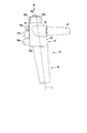
- FIG. 1A is a schematic perspective view showing an endoscope according to the first and second embodiments.
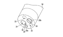
- FIG. 1B is a schematic perspective view showing the distal end hard portion of the insertion portion of the endoscope according to the first and second embodiments.
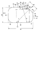
- FIG. 2 is a schematic cross-sectional view taken along the line II-II in FIG. 1A of the endoscope operation assembly according to the first embodiment.
- FIG. 3 is a schematic diagram showing the gripping part in FIG. 2 of the operation assembly of the endoscope according to the first embodiment.
- FIG. 4 is a schematic diagram showing a state in which the user has a relatively small hand holding the operation assembly of the endoscope according to the first embodiment.
- FIG. 5A is a schematic diagram illustrating a state in which a user with a relatively small hand grips the grip portion of the operation assembly of the endoscope according to the first embodiment.
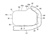
- FIG. 5B is a schematic diagram illustrating a state in which a user with a relatively small hand grips a gripping portion as a reference example for comparison with the gripping portion of the operation assembly of the endoscope according to the first embodiment.
- FIG. 6 is a schematic diagram illustrating a state where the user has a relatively large hand holding the endoscope operation assembly according to the first embodiment.
- FIG. 7A is a schematic diagram showing a state in which a user with a relatively large hand grips the grip portion of the operation assembly of the endoscope according to the first embodiment.
- FIG. 7B is a schematic diagram illustrating a state in which a user with a relatively large hand grips a gripping portion as a reference example for comparison with the gripping portion of the operation assembly of the endoscope according to the first embodiment.
- FIG. 8 is a schematic diagram showing the gripping part in FIG. 2 of the operation assembly of the endoscope according to the second embodiment.
- FIG. 9A is a schematic top view showing a state in which the user holds the operation assembly of the endoscope according to the first reference embodiment with the left hand.
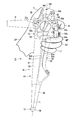
- FIG. 9B is a schematic diagram illustrating a state in which the operation assembly of the endoscope according to the first reference embodiment is viewed from the side opposite to the knob arrangement surface.
- FIG. 10A is a schematic diagram illustrating a state in which the operation assembly of the endoscope according to the second reference embodiment is viewed from the opposite side of the knob arrangement surface when the user holds the operation assembly with the left hand.
- FIG. 10B is a schematic top view showing the operation assembly of the endoscope according to the second reference embodiment.
- an endoscope 10 includes an insertion portion 12 to be inserted into a subject, an operation assembly 14 provided at a proximal end portion of the insertion portion 12, and an operation assembly 14. And a universal cord 16 connected to an external device such as a control device of the endoscope 10.
- the universal cord 16 connects the operation assembly 14 to an external device (not shown) such as a monitor or a control device.
- the virtual longitudinal axis L is prescribed
- the virtual longitudinal axis L is defined not only on the insertion portion 12 but also on the operation assembly 14 as being coaxial.
- the endoscope 10 includes an illumination optical system 22, an observation optical system 24, a treatment instrument insertion channel 26, and an air / water supply path 28, which are well-known.
- the illumination optical system 22 and the observation optical system 24 are disposed from the distal end portion of the insertion portion 12 of the endoscope 10 through the operation assembly 14 to a connector (not shown) of the universal cord 16.
- the treatment instrument insertion channel 26 has a proximal end opening 26a serving as an inlet of the treatment instrument in a grip section 44 described later of the operation assembly 14, and serves as an outlet of the treatment instrument in a distal end hard section 32 described later of the insertion section 12. It has a tip opening 26b.
- the tip opening 26b of the channel 26 also functions as the tip opening of the suction path.
- the proximal end of the suction path is disposed on a connector (not shown) of the universal cord 16 through the operation assembly 14.
- the channel 26 can suck biological tissue, physiological saline, and the like from the distal end opening 26b of the channel 26 at the distal end of the distal end hard portion 32 by a pressing operation of a suction button 54a described later.
- air / water supply path 28 for example, air is discharged from the nozzle 28 a disposed at the tip of the distal end hard portion 32 by an operation for closing a hole of an air / water supply button 54 b described later of the operation assembly 14.
- physiological saline is discharged from the nozzle 28a by the pressing operation of the water supply button 54b.
- the insertion portion 12 includes a distal end hard portion 32, a bending portion 34, and a flexible tube portion 36 in order from the distal end to the proximal end.
- the proximal end of the insertion portion 12, that is, the proximal end of the flexible tube portion 36 is connected to the operation assembly 14.
- the operation assembly 14 includes an operation unit 42 in which various mechanisms to be operated are disposed, a grip 44 (grip) 44 that is gripped by the user, and an insertion unit 12. And a bend stopper 46 for preventing buckling.
- the operation assembly 14 is arranged along the longitudinal axis L in the order of the folding stop 46, the gripping portion 44, and the operation portion 42 in this order from the side close to the insertion portion 12 toward the side away from the insertion portion 12.
- the base end of the flexible tube portion 36 is connected to the bend stopper 46 via a base (not shown).
- the bending operation knobs 52a and 52b On the outer peripheral surface of the operation unit 42, as a part of various mechanisms to be operated, the bending operation knobs 52a and 52b, the suction button (fluid control button) 54a, the air / water supply button (fluid control button) 54b, and the first To fourth switches 56a, 56b, 56c, and 56d.
- the knob disposing surface 62 on which the bending operation knobs 52 a and 52 b are disposed As the outer peripheral surface of the operation unit 42, along the circumferential direction around the longitudinal axis L, the knob disposing surface 62 on which the bending operation knobs 52 a and 52 b are disposed, the suction button 54 a, the air / water supply button 54 b, The button arrangement surface 64 on which the first and second switches 56a and 56b are arranged, and the support portion 66 that is extended between the base of the thumb T of the user's left hand LH and the base of the index finger IF. And a user facing surface (switch disposing surface) 68 on which the fourth switch 56d is disposed.
- the operation unit 42 is provided with a third switch 56c at the upper end thereof. Note that appropriate functions are set for the first to fourth switches 56a, 56b, 56c, and 56d, respectively.
- the support part 66 is mounted on the index finger IF of the user's left hand LH in a state where the user facing surface 68 is arranged so as to face the user.
- the support portion 66 is supported at a position between the base of the thumb T and the base of the index finger IF of the user's hand LH to the back of the hand.
- the lower surface of the universal cord 16 is supported near the base of the thumb T. That is, the universal cord 16 is supported at a position from between the base of the thumb T of the user's hand and the base of the index finger IF to the back of the hand. Then, the user places the thumb T of the left hand LH on the operation unit 42 or the knobs 52a and 52b through the lower side of the universal cord 16.
- the bending operation knobs 52a and 52b can remotely operate the bending portion 34 of the insertion portion 12.
- the bending portion 34 can be bent in the U direction and the D direction by rotating the bending operation knob 52a.
- the bending portion 34 can be bent in the R direction and the L direction by rotating the bending operation knob 52b. Note that the rotation axes of the bending operation knobs 52a and 52b are substantially orthogonal to the longitudinal axis L.
- a step 64 a is formed between the knob disposition surface 62, the button disposition surface 64 and the support portion 66 of the operation portion 42, and second and third grip surfaces 82 and 84 described later of the grip portion 44.
- the grip portion 44 is formed in a cylindrical shape and has a base end opening 26 a of the channel 26.
- the base end opening 26 a of the channel is disposed at a position close to the folding stop 46 in the grip 44 between the operation unit 42 and the folding stop 46.
- FIG. 2 shows the outer shell shape of the grip portion 44 along the line II-II in FIG. 1A. That is, in FIG. 2, the operation assembly 14 is viewed from the grip portion 44 side toward the operation portion 42 side.
- the illumination optical system 22, the observation optical system 24, the air / water supply path 28, and the mechanism used for the bending of the bending portion 34 are disposed inside the grip portion 44.
- the illustration of the object is omitted.
- the illustration of the built-in object is also omitted in FIGS. 3 to 8.
- FIG. 3 schematically shows the outer shell shape of the grip portion 44 shown in FIG.
- the grip portion 44 has a first grip surface (knob side grip surface) 82, a second grip surface 84, and a third grip in the circumferential direction around the longitudinal axis L as the outer peripheral surface.
- the grip portion 44 has an outer peripheral surface in the circumferential direction with respect to the longitudinal axis L formed in an annular shape by the cooperation of the first to fifth grip surfaces 82, 84, 86, 88, 90. For this reason, the grip part 44 is formed in a cylindrical shape in cooperation with the first to fifth grip surfaces 82, 84, 86, 88, 90, and is gripped by the user. Note that the gripping portion 44 is provided between the insertion portion 12 and the operation portion 42 along the longitudinal axis L.
- the third grip surface 86 is formed as a side surface disposed between the first grip surface 82 and the fourth grip surface 88. It is preferable that a part of the first grip surface 82 (a flat surface portion 82a to be described later) and the third grip surface 86 are arranged at approximately 90 ° with respect to each other via the second grip surface 84. It is preferable that the fourth grip surfaces 88 adjacent to the third grip surface 86 are arranged at approximately 90 ° with respect to each other. The fifth grip surfaces 90 adjacent to the fourth grip surface 88 are preferably arranged at approximately 90 ° with respect to each other. It is preferable that a part of the first grip surface 82 adjacent to the fifth grip surface 90 (the flat surface portion 82a) is disposed at approximately 90 °.
- the first grip surface 82 is defined as a “first surface (reference surface)”, and the fourth grip surface 88 is defined as a “second surface”.
- the fourth grip surface 88 which is defined as “second surface”, is formed on the back side of the first grip surface (first surface) 82 with respect to the longitudinal axis L. It is preferable that the first grip surface 82 and the fourth grip surface 88 have portions parallel to each other. For this reason, it is preferable that the normal line N1 of the first grip surface 82 and the normal line N4 of the fourth grip surface 88 are oriented in substantially opposite directions. It is preferable that the third grip surface 86 and the fifth grip surface 90 have portions parallel to each other.
- the normal line N3 of the third grip surface 86 and the normal line N5 of the fifth grip surface 90 are oriented in substantially opposite directions.
- the second grip surface 84 has inclined surfaces (regular surfaces in a gripping force load direction F1 described later) 84a that are inclined with respect to the first grip surface 82 and the third to fifth grip surfaces 86, 88, 90, respectively. Therefore, the normal line N2 of the second grip surface 84 is inclined with respect to the normal lines N1, N3, N4, and N5 of the first grip surface 82 and the third to fifth grip surfaces 86, 88, and 90, respectively. Yes.
- the Y-axis is parallel to the normal lines N1 and N4 in the plane regions of the first grip surface 82 and the fourth grip surface 88, and in the plane region of the third grip surface 86 and the fifth grip surface 90.
- the X axis is taken parallel to the normal lines N3 and N5.
- the width (length) of the fourth grip surface 88 in the X-axis direction is Wa
- the width (length) of the fifth grip surface 90 in the Y-axis direction is Wb.
- the width Wa is preferably larger than the width Wb at a position closer to the operation portion 42 than the folding stop 46 shown in FIG.
- the width Wa and Wb may be substantially the same in the position close to the folding stop 46 shown in FIG.
- the first grip surface 82 of the grip portion 44 is adjacent to the knob arrangement surface 62 of the operation portion 42 along the longitudinal axis L.
- the second grip surface 84 of the grip portion 44 is adjacent to the knob disposition surface 62 and the step 64a of the operation portion 42 along the longitudinal axis L.
- the third grip surface 86 of the grip portion 44 is adjacent to the step 64 a of the operation portion 42 along the longitudinal axis L.
- the fourth grip surface 88 of the grip portion 44 is adjacent to the support portion 66 of the operation portion 42 along the longitudinal axis L.
- the fifth grip surface 90 of the grip portion 44 is adjacent to the user facing surface 68 of the operation portion 42 along the longitudinal axis L.
- the boundary between the user facing surface 68 of the operation unit 42 and the fifth grip surface 90 of the grasping unit 44 is preferably formed so that both are continuous without a step, such as a substantially planar shape.
- the first grip surface 82 is provided with knobs 52 a and 52 b in positions adjacent to the first grip surface 82 around the longitudinal axis L (the first grip surface 82.
- the protrusion 83 is provided so as to protrude in the direction in which the normal line N1 extends.
- the protruding portion 83 that protrudes outward in the radial direction of the longitudinal axis L with respect to the first grip surface 82 continuously forms a peak (ridge) in the axial direction of the longitudinal axis L.
- a ridge 83a is formed.
- the ridge 83a and the inclined surface 84a of the protrusion 83 are adjacent to each other in the circumferential direction of the longitudinal axis L.
- the ridge 83a is preferably formed as a curved surface with an appropriate width such as several millimeters along the circumferential direction of the longitudinal axis L.
- the ridge 83a has a vertex portion in which the radius R is set to, for example, 1 mm to 5 mm in the circumferential direction (width direction).
- the ridge 83 a is formed from the upper end to the lower end of the grip portion 44.
- the ridge 83a does not need to be formed from the upper end to the lower end of the grip portion 44, and may be formed, for example, at a portion where the ring finger RF or the little finger LF hits.
- the first grip surface 82 includes a substantially flat flat surface portion (first surface) 82a and an inclined surface (first inclined surface) 82b formed between the flat surface portion 82a and the ridge 83a of the second grip surface 84. And have.
- the flat surface portion 82a of the first grip surface 82 is not limited to a flat surface, and may be a curved surface, or may be formed with appropriate irregularities or steps.
- the height H of the ridge 83a of the second grip surface 84 with respect to the flat portion 82a by the inclined surface 82b of the first grip surface 82 is formed smaller than the width Wb.
- the X-axis direction component X1 of the inclined surface 82b of the first grip surface 82 is It is larger than the X-axis direction component X2 from the ridge 83a to the inclined surface (slope) 84a of the second grip surface 84.
- the length of the inclined surface 82b of the first grip surface 82 is formed larger than the width W3 described later. That is, the area of the inclined surface 82b of the first grip surface 82 is increased.
- the inclined surface 82b of the first grip surface 82 increases the contact area as much as possible when the ring finger RF of the left hand LH or the little finger LF of the user with a relatively large hand is placed, for example, and the gripping force is increased. It is easy to exert on the grip 44 with the entire finger pad of the LH ring finger RF or the little finger LF.
- the inclined surface 82b of the first grip surface 82 is preferably formed as a curved surface. For this reason, the inclined surface 82b of the first grip surface 82 can have a larger area than that formed as a flat surface, and is suitable for placing the ring finger RF of the user's left hand LH or the finger pad of the little finger LF. is there.
- An imaginary line IL that virtually connects the boundary portion between the flat surface portion 82a of the first grip surface 82 and the inclined surface 82b and the ridge 83a of the second grip surface 84 is defined.
- the imaginary line IL defines the width W1 of the inclined surface 82b of the first grip surface 82.
- the width between the boundary portion between the flat portion 82a of the first grip surface 82 and the inclined surface 82b and the ridge 83a of the second grip surface 84 is defined as W1.
- the width W1 is smaller than the width W2 described later.
- the inclined surface 82b of the first grip surface 82 with respect to the imaginary line IL is formed as a convex curved surface on the lower side. For this reason, the flat part 82a and the inclined surface 82b of the 1st grip surface 82 can be smoothly continued without a level
- the inclined surface 84a is provided on the opposite side of the protruding portion 83 from the inclined surface 82b of the first grip surface 82 across the ridge 83a of the protruding portion 83, and between the ridge 83a and the third grip surface 86. Connected and inclined with respect to the first grip surface 82 (plane portion 82a) and the third grip surface 86.
- an edge 85 is formed between the inclined surface (second inclined surface) 84a of the second grip surface 84 and the third grip surface (side surface) 86. As shown in FIG. That is, the edge 85 is formed at a position closer to the fourth grip surface (second surface) 88 than the second grip surface (first surface) 82.
- the edge portion 85 extends from the upper end to the lower end of the grip portion 44, and defines an inclined surface 84a of the second grip surface 84 between the edge portion 85 and the ridge 83a.
- the edge 85 may be formed as a plane or a curved surface with an appropriate width such as several millimeters along the circumferential direction of the longitudinal axis L.
- the edge portion 85 is formed from the upper end to the lower end of the grip portion 44. The edge portion 85 does not need to be formed from the upper end to the lower end of the grip portion 44.
- the width (length) of the inclined surface 84a of the second grip surface 84 defined between the ridge 83a and the edge 85 is W2.
- a ridge 83 a having a height H is formed between the second grip surface 84 and the first grip surface 82.
- the width W2 of the inclined surface 84a of the second grip surface 84 is equal to the width (length) W3 based on the height H as compared with the state where the ridge 83a is not formed by the inclined surface 82b of the first grip surface 82.
- the volume of the internal space of the grip portion 44 can be maintained as much as possible due to the presence of the ridge 83a.
- the width W2 of the inclined surface 84a of the second grip surface 84 is increased by the width W3 to form the ridge 83a, thereby suppressing the internal space of the grip portion 44 from being reduced. Accordingly, when a built-in object (not shown) is arranged inside the grip portion 44, an appropriate volume can be secured.
- the inclined surface 84a of the second grip surface 84 has a predetermined direction F1 that acts in the opposite direction with respect to the normal line N2 on the ring of the ring finger RF and the little finger LF. It has a width W2 along the circumferential direction of the longitudinal axis L and is inclined with respect to the fourth grip surface 88 to such an extent that it can be defined in the direction (the direction toward the fourth grip surface 88).
- the third grip surface 86 and the fourth grip surface 88 cooperate to form a curved surface 87 on which the base of the finger is disposed.
- a curved surface 89 on which the part on the wrist side of the palm P is arranged in cooperation with the fourth grip surface 88 and the fifth grip surface 90. Is formed.
- the first grip surface 82 and the fifth grip surface 90 are usually not touched by the user's hand, but the first grip surface 82 and the fifth grip surface 90 cooperate to form the curved surface 81. It is preferable that The curved surfaces 81, 87, and 89 are preferably formed in a convex shape outward in the radial direction with respect to the longitudinal axis L.
- the inclined surface 84a of the second grip surface 84 is used as a load direction defining surface for gripping force that defines the direction in which the gripping force gripped by the ring finger RF or the little finger LF of the user's left hand LH is applied.
- an imaginary line (second imaginary line) directed in the opposite direction to the normal N2 extending from the center position along the circumferential direction (width direction) of the longitudinal axis L. It is preferable that F1 virtually intersects any one of the positions including the curved surfaces 87 and 89 in the fourth grip surface 88.
- the imaginary line F1 extends from the center position along the longitudinal axis L of the inclined surface (second inclined surface) 84a of the second grip surface 84.
- the angle ⁇ between the fourth grip surface 88 and the virtual line F1 is preferably about 45 °, for example.
- the orientation of the imaginary line F1 directed to the opposite side to the normal line N2 at the center of the width W2 of the second grip surface 84 only needs to be directed to the fourth grip surface 88 including the curved surfaces 87 and 89. .
- the inclination angle of the inclined surface 84a of the second grip surface 84 with respect to the flat portion 82a of the first grip surface (first surface) 82 is appropriately set within a range where the virtual line F1 intersects the fourth grip surface 88. Is done.
- the angle ⁇ of the inclined surface 84a of the second grip surface 84 with respect to the flat surface portion 82a of the first grip surface 82 is an obtuse angle. That is, the angle ⁇ of the surface S defined by the ridge 83a and the edge 85 of the protrusion 83 of the second grip surface 84 with respect to the flat portion 82a of the first grip surface 82 is an obtuse angle.
- the angle ⁇ of the inclined surface 84a of the second grip surface 84 with respect to the inclined surface 82b of the first grip surface 82 is preferably an obtuse angle, but depending on the intersection position of the load direction F1 and the fourth grip surface 88. May be acute.
- the user places the support unit 66 on the index finger IF of the user's left hand LH with the user facing surface 68 of the operation unit 42 and the fifth grip surface 90 of the gripping unit 44 facing the user. .
- the user places the thumb T of the left hand LH on the user facing surface 68 of the operation unit 42 or the knobs 52a and 52b through the lower side of the universal cord 16.
- the index finger IF is placed in the vicinity of the buttons 54a and 54b or the first switch 56a.
- the middle finger MF is arranged at a position where the knob 52a can be supported through the button arrangement surface 64 or through the lower side of the step 64a.
- the user facing surface 68 and the fifth grip surface 90 can face the front of the user.
- the bending operation knobs 52a and 52b are disposed on the right side of the user, and the universal cord 16 is disposed on the left side of the user.
- the finger pads of the ring finger RF and the little finger LF are arranged on the second grip surface 84.
- the distal node DP of the ring finger RF and the little finger LF is disposed on the second grip surface 84
- the middle node MP is disposed on the third grip surface 86
- the base node PP is disposed on the fourth grip surface 88 including the curved surface 87.
- the finger ring of the ring finger RF and the little finger LF contacts the inclined surface 84a of the second grip surface 84 entirely in surface contact. For this reason, a user with a relatively small hand can make surface contact with the inclined surface 84a of the second grip surface 84 with the fingers RF and LF. Accordingly, even if the user has a relatively small hand, the fingers RF and LF and the inclined surface 84a of the second grip surface 84 are in surface contact with each other, so that the operation assembly 14 of the endoscope 10 according to the present embodiment is appropriately set.
- the width W2 around the longitudinal axis L of the inclined surface (second inclined surface) 84a of the second grip surface 84 is the width around the longitudinal axis of the inclined surface (first inclined surface) 82b of the first grip surface 82. Greater than W1. Further, the inclined surface 82 b of the first grip surface 82 and the inclined surface 84 a of the second grip surface 84 extend along the longitudinal axis L.
- the finger on the inclined surface 84a of the second grip surface 84 The area where RF and LF are in contact is larger than the area where the fingers RF and LF are in contact with each other on the inclined surface 82 b of the first grip surface 82. Therefore, even if the user has a relatively small hand, the fingers RF and LF can be kept in contact with the inclined surface 84a of the second grip surface 84 in a region having a larger area.
- the operation assembly 14 of the endoscope 10 when a user with a relatively small hand grips the operation assembly 14 of the endoscope 10 according to the present embodiment, it can be stably gripped. Even if the usage time of the endoscope 10 is increased, the surface pressure of the fingers RF and LF against the finger pad can be received by the entire finger pad, so that the gripping force can be maintained and maintained. is there.
- the gripping force is applied to the inclined surface 84a of the second grip surface 84 by the ring finger of the ring finger RF and the little finger LF.
- the direction F1 of the gripping force is directed not to the fifth grip surface 90 but to the fourth grip surface 88 where most of the palm P is disposed. That is, the grip portion 44 of the operation assembly 14 of the endoscope 10 according to this embodiment uses the palm P to determine the direction F1 of the grip force applied to the inclined surface 84a of the second grip surface 84 in the gripping state of the operation assembly 14. It is defined on the fourth grip surface 88 to be supported.
- the inclined surface 84a of the second grip surface 84 is obtained.
- the gripping force by the finger pad of the ring finger RF and the little finger LF acts as a force for pressing the fourth grip surface 88 against the palm P.
- the stable gripping state is maintained by pressing the fourth grip surface 88 against the palm P. Therefore, even when the user has a relatively small hand, when the operation assembly 14 of the endoscope 10 according to the present embodiment is appropriately gripped, the gripper 44 is kept slippery while being gripped for a long time. It is possible to easily maintain the gripping force. Note that a user with a relatively small hand can also maintain a gripping force easily by hooking his / her finger on the edge 85 so that the gripping portion 44 can be kept slippery.
- FIG. 5B shows an example of the grip portion 144 in which the second grip surface 84 is not formed as a reference for comparison with the grip portion 44 according to the present embodiment.
- the distal node DP of the ring finger RF and the little finger LF is disposed on the curved surface 185
- the middle node MP is disposed on the third grip surface 186
- the base node PP is disposed on the fourth grip surface 88 including the curved surface 87.
- a user with a relatively small hand does not easily reach the first grip surface 182 with the fingers RF and LF. Therefore, the contact portion between the user's fingers RF and LF and the grip portion 144 is a curved surface 185. That is, in the example shown in FIG.
- the ring finger RF and the little finger LF are placed on the curved surface 185 between the first grip surface 182 and the third grip surface 186.
- a part of the finger pad of the ring finger RF and the little finger LF contacts the curved surface 185. Since the curved surfaces 184 and 185 each have a top, a user with a relatively small hand touches the curved surface 185 with a part of the finger pad of the ring finger RF and the little finger LF, but it is difficult to contact the entire surface. For this reason, even if the user with a relatively small hand holds the operation assembly of the endoscope shown in FIG. 5B appropriately, the ring finger RF and the little finger are more slippery than in the state shown in FIG.
- the region spanning the second grip surface 184 and the third grip surface 186 in FIG. 5B may be pressed by a part of the finger pad of the ring finger RF and the little finger LF.
- a gripping force is applied toward the fifth grip surface 90 rather than the palm P that supports the fourth grip surface 88. For this reason, the force which presses the holding part 144 against the palm P is weakened.
- the middle finger MF has been described as being arranged at a position where the bending operation knob 52a can be supported.
- the middle finger MF may be disposed on the second grip surface 84 in the same manner as the ring finger RF and the little finger LF.
- the grip portion 44 can generally be gripped by one or more fingers from the third finger to the fifth finger, or by two fingers, the fourth finger and the fifth finger.
- the user holds the operation assembly 14 of the endoscope 10. 7A, the ring finger RF and the little finger LF are placed on the first grip surface 82. As shown in FIG. At this time, for example, the distal node DP of the ring finger RF and the little finger LF is the first inclined surface 82b of the first grip surface 82, the middle node MP is the second grip surface 84, and the base node PP is the third grip surface 86. To place.
- the finger ring of the ring finger RF and the little finger LF is in full contact with the inclined surface 82b of the first grip surface 82 by surface contact. For this reason, a user with a relatively large hand can make surface contact between the fingers RF and LF and the inclined surface 82b of the first grip surface 82. Therefore, even if the user has a relatively large hand, the fingers RF and LF and the inclined surface 82b of the first grip surface 82 are in surface contact with each other, so that the operation assembly 14 of the endoscope 10 according to the present embodiment is appropriately set.
- the ridge 83a has a curved surface with a radius R set to 1 mm to 5 mm, for example. For this reason, the contact area between the ridge 83a and the fingers RF and LF is increased, and the anti-slip effect is increased.
- the gripping force is applied to the inclined surface 82b of the first grip surface 82 by the finger pad of the ring finger RF and the little finger LF.
- a virtual line (first virtual line) F ⁇ b> 2 extending in a direction orthogonal to the virtual line IL from the center position of the virtual line IL intersects the inclined surface 82 b of the first grip surface 82.
- the fourth grip surface 88 virtually intersects with any position including the curved surface 87.
- the direction F2 of the gripping force is directed toward the fourth grip surface 88 on which most of the palm P is disposed.
- the gripping portion 44 of the operation assembly 14 of the endoscope 10 uses the palm P to indicate the direction F2 of the gripping force applied to the inclined surface 82b of the first grip surface 82 when the operation assembly 14 is gripped. It is defined on the fourth grip surface 88 to be supported. For this reason, the gripping force by the finger pad of the ring finger RF and the little finger LF on the inclined surface 82b of the first grip surface 82 acts as a force for pressing the fourth grip surface 88 against the palm P. Thus, the stable gripping state is maintained by pressing the fourth grip surface 88 against the palm P.
- the gripper 44 is kept slippery while being gripped for a long time. It is possible to easily maintain the gripping force. Note that a user with a relatively large hand can also maintain a gripping force easily by hooking his / her finger on the edge 85 so that the gripper 44 can be kept slippery.
- FIG. 7B shows an example of the grip portion 144 in which the second grip surface 84 is not formed as a reference for comparison with the grip portion 44 according to the present embodiment.
- the distal node DP of the ring finger RF and the little finger LF is disposed on the inclined surface 182b and the ridge 183a of the first grip surface 182
- the middle node MP is disposed on the curved surface 185
- the base node PP is disposed on the third grip surface 186. That is, in the example shown in FIG. 7B, the ring finger RF and the little finger LF are placed on the flat surface 182a of the first grip surface 182 and the inclined surface 182b of the ridge 183a.
- the inclined surface 182b has a larger inclination than the inclined surface 82b of the first grip surface 82 shown in FIG. 7A.
- the user with a relatively large hand contacts the ring finger 182 and part of the finger pad of the little finger LF with respect to the inclined surface 182b.
- the ring finger RF and the little finger LF maintain the grasping force more than the state shown in FIG. 7A. Difficult and slippery.
- the middle finger MF is described as being disposed at a position where the bending operation knob 52a can be pressed.
- the middle finger MF may be arranged on the inclined surface 82b of the first grip surface 82 in the same manner as the ring finger RF and the little finger LF.
- the user firmly holds the insertion portion 12 with the right hand (not shown) in a state where the operation assembly 14 of the endoscope 10 is held with the left hand LH as described above. And a user performs operation which twists the insertion part 12 by moving a right hand suitably, for example.
- a force for canceling the twist of the insertion portion 12 acts on the operation assembly 14.
- the gripping force loading directions F1 and F2 due to the ring of the ring finger RF and the little finger LF are used. Faces the fourth grip surface 88.
- the endoscope 10 is adjacent along the longitudinal axis L to a surface (knob disposition surface) 62 of the operation unit 42 on the side where the bending operation knobs 52a and 52b are provided.
- the first surface (first grip surface) 82 is defined as a surface to be formed, and a ridge 83a protruding outward at a position adjacent to the first surface 82 in the circumferential direction of the longitudinal axis L is formed.
- 44 is provided on the opposite side to the first surface along the circumferential direction of the longitudinal axis L with respect to the ridge 83a, and the fourth grip surface on the opposite side to the first surface 82 of the grip portion 44.
- An inclined surface (regulating surface) 84a that defines the load direction F1 of the gripping force when gripped by the user toward 88 is formed.
- the normal line N2 of the inclined surface 84a of the second grip surface 84 is obtained.
- a gripping force can be applied toward the opposite side.
- the fourth grip surface 88 can be pressed against the palm P by the gripping force of the ring finger RF and the little finger LF.
- the contact area of the ring finger RF and the little finger LF with respect to the grip portion 44 can be secured, and the grip portion 44 of the operation assembly 14 can be stably gripped.
- a user with a relatively large hand can grip a portion of the first grip surface (first surface) 82 adjacent to the ridge 83a with a finger pad such as a ring finger RF or a little finger LF.
- the fourth grip surface 88 can be pressed against the palm P by the gripping force of the ring finger RF and the little finger LF. Therefore, even a user with a relatively large hand can secure a contact area by the ring finger RF and the little finger LF with respect to the grip portion 44, and can stably grip the grip portion 44 in the operation assembly 14.
- the gripping portion 44 is not slippery and can be stably gripped by appropriately gripping the gripping portion and defining the direction in which the gripping force is applied.
- the virtual line F1 in the direction opposite to the normal line N2 with respect to the inclined surface 84a of the second grip surface 84 intersects the fourth grip surface 88, the user with a relatively small hand can use the ring finger RF and the little finger LF. Even when it is disposed on the inclined surface 84a, it is possible to reliably apply a gripping force toward the fourth grip surface 88.
- the width (lateral width) W2 of the inclined surface 84a of the second grip surface 84 can be secured relatively long.
- the internal space of the holding part 44 can be increased by increasing the width W2 of the inclined surface 84a.
- the ridge 83a is continuously formed on the first grip surface (first surface) 82, it is possible to secure a contact area by the ring finger RF of the left hand LH of the user having a relatively large hand and the finger pad of the little finger LF.
- the ridge 83a is provided at the edge of the second grip surface 84 in the circumferential direction with respect to the longitudinal axis L, and a user with a relatively large hand hangs the ring finger RF or the little finger LF on the ridge 83a to prevent slippage. It can be.
- a proximal end opening 26a of the treatment instrument insertion channel 26 is formed at a position close to the insertion portion 12 (position close to the folding stop 46). Since the second grip surface (slope) 84 is formed up to the vicinity of the proximal end opening 26a, the user can take a large grip position in the grip portion 44, and can freely determine the grip position. be able to.
- the ring finger RF and the little finger LF or the middle finger MF are arranged on the inclined surface 82b of the first grip surface 82 or the inclined surface 84a of the second grip surface 84 of the grip portion 44. At least one of the ring finger RF, the little finger LF, and the middle finger MF is disposed on the inclined surface 82b of the first grip surface 82 or the inclined surface 84a of the second grip surface 84 of the grasping portion 44, and appropriate treatment by the endoscope 10 is performed. It is also suitable to be advanced.
- the inclined surface 84a of the second grip surface 84 may be formed as a convex surface protruding outward in the radial direction with respect to the longitudinal axis L, but it is preferable that the inclined surface 84a can be seen with a flat surface.
- the convex shape of the inclined surface 84a of the second grip surface 84 is set by the contact area because it becomes difficult to grip when the contact area with the finger pad of the ring finger RF or the little finger LF becomes small.
- the inclined surface 84a of the second grip surface 84 has a non-slip effect on the finger pad of the ring finger RF or the little finger LF, such as a combination of a plurality of convex portions or a plurality of convex portions and a plurality of concave portions. It may be formed. In addition, a combination of a plurality of convex portions, or a combination of a plurality of convex portions and a plurality of concave portions can recognize the position where the ring finger RF or the little finger LF is touched by touch.
- the plurality of convex portions of the inclined surface 84a or the base portion of the combination of the plurality of convex portions and the plurality of concave portions is formed as a flat surface. That is, it is preferable that at least a part of the inclined surface 84a is planar. Further, when a combination of a plurality of convex portions and a plurality of concave portions is formed, it can be said that at least a part of the inclined surface 84a is convex and at least a part of the inclined surface 84a is concave.
- the second embodiment will be described with reference to FIG.
- This embodiment is a modification of the first embodiment, and the same members as those described in the first embodiment or members having the same functions are denoted by the same reference numerals as much as possible, and detailed description thereof is omitted.
- the inclined surface 84b of the second grip surface 84 is formed in a concave shape. That is, the inclined surface 84 b is formed in a convex shape toward the longitudinal axis L with respect to the virtual surface S defined by the ridge 83 a and the edge portion 85. It is preferable that the concave inclined surface 84 b is continuously formed to have an appropriate length from the upper end to the lower end of the grip portion 44.
- the depth of the concave inclined surface 84b is preferably recessed in a range smaller than the general thickness of the user's ring finger RF or little finger LF, for example. When the inclined surface 84b has such a depth, it is easy to bring the ring finger RF or little finger LF into contact with the bottom surface of the inclined surface 84b.
- the direction F2 in which the gripping force is applied by the finger pad of the ring finger RF or the little finger LF by gripping can be directed to the fourth grip surface 88.
- a surface (here, a virtual surface) S defined by the ridge 83a and the edge portion 85 of the second grip surface 84 with respect to the flat surface portion 82a of the first grip surface 82 is at an obtuse angle ⁇ .
- the virtual surface S of the second grip surface 84 is preferably located at an obtuse angle ⁇ with respect to the inclined surface 82 b of the first grip surface 82, but the intersection of the load direction F ⁇ b> 2 and the fourth grip surface 88. Depending on the position, it may be at an acute angle.
- the first reference embodiment will be described with reference to FIGS. 9A and 9B.
- the same members as those described in the first and second embodiments or members having the same functions are denoted by the same reference numerals as much as possible, and detailed description thereof is omitted.
- the structure of the suction button 54a and the air / water supply button 54b, which will be described later, and the arrangement of the universal cord 16 are the same as those in the operation assembly 14 of the endoscope 10 described in the first and second embodiments. It can be used appropriately.
- the pressing direction of the suction button 54a is formed at an angle ⁇ (0 ° ⁇ ⁇ 90 °) with respect to the rotation shaft 53 of the bending operation knobs 52a, 52b.
- the air / water feed button 54b is formed so that the air / water feed button 54b is pressed at an angle ⁇ (0 ° ⁇ ⁇ 90 °) with respect to the rotation shaft 53 of the bending operation knobs 52a and 52b. ing. That is, the buttons 54a and 54b are arranged so that the pressing directions thereof are inclined toward the bending operation knobs 52a and 52b.
- FIG. 9A the pressing direction of the suction button 54a is formed at an angle ⁇ (0 ° ⁇ ⁇ 90 °) with respect to the rotation shaft 53 of the bending operation knobs 52a, 52b.
- the universal cord 16 is formed with a larger width along the axial direction of the rotation axis of the bending operation knobs 52a and 52b of the operation unit 14 than in the conventional state indicated by the broken line. Therefore, the base of the thumb T of the left hand LH can be arranged on the back side, and for example, the index finger IF and the middle finger MF can easily reach the switches 56a to 56d, the buttons 54a and 54b, and the like.
- the distance between the buttons 54a and 54b and the base side of the finger of the index finger IF or the middle finger MF may be close.
- the universal cord 16 is arranged on the left side in FIG. 9A than the conventional one (see the broken line in FIG. 9A), so that the base of the thumb T is arranged on the back side and the fingers reach various switches and buttons.
- the buttons 54a and 54b tilt toward the knobs 52a and 52b, the buttons 54a and 54b can be easily operated even when the base side of the finger is close to the buttons 54a and 54b.
- the first switch 56 a has a main pressing direction defined in a direction orthogonal to the rotation shaft 53.
- the first switch 56a it is preferable to use a switch that can be operated by pressing from various directions such as a side as well as a direction orthogonal to the rotation shaft 53.
- FIGS. 10A and 10B the same members as those described in the first and second embodiments or members having the same functions are denoted by the same reference numerals as much as possible, and detailed description thereof is omitted.
- the arrangement of the air / water supply button 54b described later in this reference form can be used as appropriate in the operation assembly 14 of the endoscope 10 described in the first and second embodiments.
- the button disposition surface 64 includes a step 65c, a distal surface (first installation surface) 65a distal to the virtual longitudinal axis L, and a proximal proximal surface (first surface). 2 installation surface) 65b.
- a step 64a between the proximal surface 65b and the grip portion 44 is smaller than the state shown in FIGS. 1A and 2.
- a suction button 54a is disposed on the distal surface 65a.
- An air / water supply button 54b is disposed on the proximal surface 65b.
- the pressing surface of the air / water feeding button 54b is set closer to the virtual longitudinal axis L than the pressing surface of the suction button 54a. For this reason, the air / water supply button 54b is hidden behind the suction button 54a in FIG. 10B.
- Auxiliary operation for holding the bending operation knobs 52a and 52b may be performed using the middle finger MF or the like.
- the air / water supply button 54b is arranged as in this reference embodiment, interference with the air / water supply button 54b when the bending operation knobs 52a and 52b are held by the middle finger MF and the ring finger RF is suppressed. For this reason, it becomes easy to perform an auxiliary operation for holding the bending operation knobs 52a and 52b.
- the press direction of the 1st switch 56a and the suction button 54a is orthogonal to the rotating shaft 53 of knob 52a, 52b.
Abstract
L'invention concerne un endoscope qui présente une section d'actionnement qui est pourvue : d'un bouton d'actionnement de flexion ; d'une section de préhension cylindrique disposée entre une section d'insertion et la section d'actionnement et saisie par un utilisateur. La section de préhension possède : une première surface adjacente, dans une direction d'axe longitudinal, à une surface sur laquelle le bouton d'actionnement de flexion est situé ; une seconde surface formée sur le côté inverse de la première surface dans la direction d'axe longitudinal ; une surface latérale formée entre la première surface et la seconde surface ; une saillie faisant saillie radialement vers l'extérieur par rapport à l'axe longitudinal à un emplacement adjacent à la première surface autour de l'axe longitudinal ; une première surface inclinée, disposée sur le côté de la saillie, qui est adjacent à la première surface, et inclinée par rapport à la première surface de façon à être située sur le côté inverse de la seconde surface ; une seconde surface inclinée qui est située sur le côté de la saillie opposé à la première surface inclinée, qui relie la saillie et la surface latérale, et qui est inclinée par rapport à la première surface et à la surface latérale.
Priority Applications (4)
| Application Number | Priority Date | Filing Date | Title |
|---|---|---|---|
| JP2017530243A JP6177491B2 (ja) | 2015-08-18 | 2016-08-08 | 内視鏡 |
| CN201680021414.XA CN107427194B (zh) | 2015-08-18 | 2016-08-08 | 内窥镜 |
| EP16837026.0A EP3338615A4 (fr) | 2015-08-18 | 2016-08-08 | Endoscope |
| US15/899,391 US10939809B2 (en) | 2015-08-18 | 2018-02-20 | Grasping section of an endoscope |
Applications Claiming Priority (2)
| Application Number | Priority Date | Filing Date | Title |
|---|---|---|---|
| JP2015-161041 | 2015-08-18 | ||
| JP2015161041 | 2015-08-18 |
Related Child Applications (1)
| Application Number | Title | Priority Date | Filing Date |
|---|---|---|---|
| US15/899,391 Continuation US10939809B2 (en) | 2015-08-18 | 2018-02-20 | Grasping section of an endoscope |
Publications (1)
| Publication Number | Publication Date |
|---|---|
| WO2017030036A1 true WO2017030036A1 (fr) | 2017-02-23 |
Family
ID=58050842
Family Applications (1)
| Application Number | Title | Priority Date | Filing Date |
|---|---|---|---|
| PCT/JP2016/073309 WO2017030036A1 (fr) | 2015-08-18 | 2016-08-08 | Endoscope |
Country Status (5)
| Country | Link |
|---|---|
| US (1) | US10939809B2 (fr) |
| EP (1) | EP3338615A4 (fr) |
| JP (1) | JP6177491B2 (fr) |
| CN (1) | CN107427194B (fr) |
| WO (1) | WO2017030036A1 (fr) |
Cited By (2)
| Publication number | Priority date | Publication date | Assignee | Title |
|---|---|---|---|---|
| JP2019063180A (ja) * | 2017-09-29 | 2019-04-25 | 富士フイルム株式会社 | 内視鏡 |
| CN110381799A (zh) * | 2017-03-08 | 2019-10-25 | 安布股份有限公司 | 用于内窥镜的手柄 |
Families Citing this family (5)
| Publication number | Priority date | Publication date | Assignee | Title |
|---|---|---|---|---|
| JP1574130S (fr) * | 2016-11-17 | 2017-04-17 | ||
| JP1574125S (fr) * | 2016-11-17 | 2017-04-17 | ||
| JP1574129S (fr) * | 2016-11-17 | 2017-04-17 | ||
| WO2018098465A1 (fr) | 2016-11-28 | 2018-05-31 | Inventio, Inc. | Endoscope à arbre jetable séparable |
| USD1018844S1 (en) | 2020-01-09 | 2024-03-19 | Adaptivendo Llc | Endoscope handle |
Citations (4)
| Publication number | Priority date | Publication date | Assignee | Title |
|---|---|---|---|---|
| JPS5698206U (fr) * | 1979-12-26 | 1981-08-04 | ||
| JP1386276S (fr) * | 2009-10-16 | 2010-04-26 | ||
| WO2011132544A1 (fr) * | 2010-04-19 | 2011-10-27 | オリンパスメディカルシステムズ株式会社 | Section de commande d'un endoscope, et endoscope |
| JP1470841S (fr) * | 2012-09-12 | 2013-06-03 |
Family Cites Families (16)
| Publication number | Priority date | Publication date | Assignee | Title |
|---|---|---|---|---|
| JPS63143301U (fr) * | 1987-03-12 | 1988-09-21 | ||
| US4979497A (en) * | 1989-06-06 | 1990-12-25 | Olympus Optical Co., Ltd. | Endoscope |
| JP4356041B2 (ja) * | 1999-03-05 | 2009-11-04 | フジノン株式会社 | 内視鏡の手元操作部構造 |
| JP3729322B2 (ja) * | 2000-02-03 | 2005-12-21 | フジノン株式会社 | 内視鏡の手元操作部 |
| JP4716549B2 (ja) * | 2000-08-22 | 2011-07-06 | オリンパス株式会社 | 電子内視鏡 |
| JP2004109222A (ja) * | 2002-09-13 | 2004-04-08 | Olympus Corp | 内視鏡装置 |
| JP4456499B2 (ja) * | 2005-02-10 | 2010-04-28 | 株式会社マキタ | 作業工具 |
| JP5259113B2 (ja) * | 2006-07-21 | 2013-08-07 | オリンパスメディカルシステムズ株式会社 | 内視鏡 |
| JP4970870B2 (ja) * | 2006-08-10 | 2012-07-11 | オリンパスメディカルシステムズ株式会社 | 内視鏡の操作装置 |
| JP4533907B2 (ja) * | 2007-04-02 | 2010-09-01 | オリンパス株式会社 | 操作ノブアタッチメント |
| JP5464817B2 (ja) * | 2008-04-01 | 2014-04-09 | オリンパスメディカルシステムズ株式会社 | 手持式内視鏡 |
| EP2732753A4 (fr) * | 2012-04-11 | 2015-09-30 | Olympus Medical Systems Corp | Couvercle d'interrupteur, dispositif d'interrupteur et endoscope |
| EP2868252A4 (fr) * | 2012-10-22 | 2016-07-13 | Olympus Corp | Endoscope |
| WO2015050062A1 (fr) * | 2013-10-02 | 2015-04-09 | オリンパスメディカルシステムズ株式会社 | Dispositif à introduire |
| WO2015087814A1 (fr) * | 2013-12-13 | 2015-06-18 | オリンパス株式会社 | Section d'actionnement pour un dispositif d'introduction dans une ouverture, et dispositif d'introduction dans une ouverture |
| WO2016027521A1 (fr) * | 2014-08-22 | 2016-02-25 | オリンパス株式会社 | Dispositif d'opération de cintrage pour endoscope, et endoscope |
-
2016
- 2016-08-08 WO PCT/JP2016/073309 patent/WO2017030036A1/fr active Application Filing
- 2016-08-08 JP JP2017530243A patent/JP6177491B2/ja active Active
- 2016-08-08 CN CN201680021414.XA patent/CN107427194B/zh active Active
- 2016-08-08 EP EP16837026.0A patent/EP3338615A4/fr not_active Withdrawn
-
2018
- 2018-02-20 US US15/899,391 patent/US10939809B2/en active Active
Patent Citations (4)
| Publication number | Priority date | Publication date | Assignee | Title |
|---|---|---|---|---|
| JPS5698206U (fr) * | 1979-12-26 | 1981-08-04 | ||
| JP1386276S (fr) * | 2009-10-16 | 2010-04-26 | ||
| WO2011132544A1 (fr) * | 2010-04-19 | 2011-10-27 | オリンパスメディカルシステムズ株式会社 | Section de commande d'un endoscope, et endoscope |
| JP1470841S (fr) * | 2012-09-12 | 2013-06-03 |
Non-Patent Citations (1)
| Title |
|---|
| See also references of EP3338615A4 * |
Cited By (3)
| Publication number | Priority date | Publication date | Assignee | Title |
|---|---|---|---|---|
| CN110381799A (zh) * | 2017-03-08 | 2019-10-25 | 安布股份有限公司 | 用于内窥镜的手柄 |
| JP2019063180A (ja) * | 2017-09-29 | 2019-04-25 | 富士フイルム株式会社 | 内視鏡 |
| US11213187B2 (en) | 2017-09-29 | 2022-01-04 | Fujifilm Corporation | Endoscope |
Also Published As
| Publication number | Publication date |
|---|---|
| CN107427194A (zh) | 2017-12-01 |
| US20180168436A1 (en) | 2018-06-21 |
| JP6177491B2 (ja) | 2017-08-09 |
| JPWO2017030036A1 (ja) | 2017-10-19 |
| EP3338615A1 (fr) | 2018-06-27 |
| US10939809B2 (en) | 2021-03-09 |
| CN107427194B (zh) | 2018-12-14 |
| EP3338615A4 (fr) | 2019-05-22 |
Similar Documents
| Publication | Publication Date | Title |
|---|---|---|
| JP6177491B2 (ja) | 内視鏡 | |
| US10206559B2 (en) | Endoscope apparatus | |
| JP5054250B2 (ja) | 内視鏡操作部、内視鏡 | |
| JP6395989B1 (ja) | 医療器具 | |
| JP2022528173A (ja) | 医療機器用グリップ | |
| US20100043120A1 (en) | Medical glove | |
| US10973395B2 (en) | Endoscope cover, endoscope, cover unit, and endoscope unit | |
| WO2015087815A1 (fr) | Section de fonctionnement pour dispositif d'introduction en ouverture et dispositif d'introduction en ouverture | |
| US10478050B2 (en) | Operation device for into-bore introduction device, and into-bore introduction device | |
| JP5829362B2 (ja) | 導入装置 | |
| JP6124819B2 (ja) | 内視鏡用操作部及び内視鏡 | |
| JP6010265B1 (ja) | 内視鏡 | |
| WO2016152306A1 (fr) | Instrument de traitement médical | |
| CN215078210U (zh) | 一种用于内镜的旋钮套 | |
| US11832995B2 (en) | Graspable surgical device | |
| JP6839548B2 (ja) | 内視鏡 | |
| TWI623335B (zh) | Separate safety needle sleeve device and safety needle device thereof | |
| JP6165073B2 (ja) | 孔内導入装置用操作部及び孔内導入装置 | |
| JP5829363B2 (ja) | 導入装置 | |
| TWI361129B (fr) | ||
| JP2009020875A (ja) | コンピュータ用マウス | |
| JP2009273592A (ja) | 内視鏡用フード |
Legal Events
| Date | Code | Title | Description |
|---|---|---|---|
| 121 | Ep: the epo has been informed by wipo that ep was designated in this application |
Ref document number: 16837026 Country of ref document: EP Kind code of ref document: A1 |
|
| ENP | Entry into the national phase |
Ref document number: 2017530243 Country of ref document: JP Kind code of ref document: A |
|
| NENP | Non-entry into the national phase |
Ref country code: DE |
|
| WWE | Wipo information: entry into national phase |
Ref document number: 2016837026 Country of ref document: EP |