WO2017017958A1 - 弾性クローラ - Google Patents
弾性クローラ Download PDFInfo
- Publication number
- WO2017017958A1 WO2017017958A1 PCT/JP2016/003496 JP2016003496W WO2017017958A1 WO 2017017958 A1 WO2017017958 A1 WO 2017017958A1 JP 2016003496 W JP2016003496 W JP 2016003496W WO 2017017958 A1 WO2017017958 A1 WO 2017017958A1
- Authority
- WO
- WIPO (PCT)
- Prior art keywords
- crawler
- lug
- elastic
- width direction
- region
- Prior art date
- Legal status (The legal status is an assumption and is not a legal conclusion. Google has not performed a legal analysis and makes no representation as to the accuracy of the status listed.)
- Ceased
Links
Images




Classifications
-
- B—PERFORMING OPERATIONS; TRANSPORTING
- B62—LAND VEHICLES FOR TRAVELLING OTHERWISE THAN ON RAILS
- B62D—MOTOR VEHICLES; TRAILERS
- B62D55/00—Endless track vehicles
- B62D55/08—Endless track units; Parts thereof
- B62D55/18—Tracks
- B62D55/24—Tracks of continuously flexible type, e.g. rubber belts
- B62D55/244—Moulded in one piece, with either smooth surfaces or surfaces having projections, e.g. incorporating reinforcing elements
-
- B—PERFORMING OPERATIONS; TRANSPORTING
- B62—LAND VEHICLES FOR TRAVELLING OTHERWISE THAN ON RAILS
- B62D—MOTOR VEHICLES; TRAILERS
- B62D55/00—Endless track vehicles
- B62D55/08—Endless track units; Parts thereof
- B62D55/18—Tracks
- B62D55/24—Tracks of continuously flexible type, e.g. rubber belts
- B62D55/253—Tracks of continuously flexible type, e.g. rubber belts having elements interconnected by one or more cables or like elements
-
- B—PERFORMING OPERATIONS; TRANSPORTING
- B62—LAND VEHICLES FOR TRAVELLING OTHERWISE THAN ON RAILS
- B62D—MOTOR VEHICLES; TRAILERS
- B62D55/00—Endless track vehicles
- B62D55/08—Endless track units; Parts thereof
- B62D55/18—Tracks
- B62D55/26—Ground engaging parts or elements
Definitions
- the present invention relates to an elastic crawler.
- the conventional elastic crawler by providing a plurality of lugs raised from the outer peripheral surface of the crawler main body so as to overlap with the cored bar embedded in the crawler main body at intervals in the circumferential direction, Among the outer peripheral surfaces of the elastic crawlers, there are ones in which grooves extending in the crawler width direction are provided between the core bars adjacent in the crawler circumferential direction (see, for example, Patent Document 1). These groove portions are formed on the outer peripheral surface of the elastic crawler at intervals in the crawler circumferential direction, thereby helping to improve the flexibility of the elastic crawler when the elastic crawler is wound or running.
- an elastic crawler improves the transmission of driving force to snow by the effect of so-called snow column shearing force by stepping and hardening the snow between a plurality of lugs when running on a snowy road.
- the lateral shift can be suppressed.
- the performance of stiffening and softening a soft ground such as snow inside a plurality of lugs (hereinafter also referred to as “packing property”) is important as the performance of the elastic crawler.
- the conventional elastic crawler has a problem that, for example, when stepping on snow, the stepping of the snow is insufficient and the core metal escapes along the groove extending in the crawler width direction. There was room for improvement in packing properties.
- An object of the present invention is to provide an elastic crawler in which transmission of a driving force to snow or soft ground is improved by improving packing properties when the elastic crawler travels.
- An elastic crawler includes a crawler body formed endlessly by an elastic body, a cored bar embedded in the crawler body at intervals in the crawler circumferential direction, and extending in the crawler width direction, and the crawler body And a lug that surrounds a predetermined region that overlaps with the cored bar as viewed in the crawler thickness direction. According to the elastic crawler according to the present invention, it is possible to improve the transmission of driving force to snow or soft ground by improving the packing property.
- the elastic crawler which concerns on this invention WHEREIN: It is preferable that the said lug is provided with the open part which open
- the direction in which the opening portion opens the region is preferably a direction along the crawler width direction. In this case, the lateral shift can be suppressed.
- a direction in which the opening portion opens the region is a direction toward the center side in the crawler width direction along the crawler width direction. In this case, it is possible to further improve the transmission of driving force to snow or soft ground, and to further suppress the lateral displacement.
- the elastic crawler includes two lugs that respectively surround the two regions spaced apart in the crawler width direction, and the two lugs each open the region, and It is preferable to face each other. In this case, it is possible to further improve the transmission of driving force to snow or soft ground, and to further suppress the lateral displacement.
- the lug surrounds all directions of the region. In this case, by improving the packing properties, it is possible to improve the transmission of driving force to snow or soft ground.
- a part of the lug surrounding the predetermined region is a central lug that overlaps the center of the cored bar in the crawler width direction when viewed in the crawler thickness direction. In this case, the packing property can be further improved.
- the lug overlaps a plurality of the core bars adjacent in the crawler circumferential direction when viewed in the crawler thickness direction.
- the durability of the lugs can be improved by increasing the volume of each lug.
- the elastic crawler it is preferable that at least one edge in the crawler circumferential direction of the region coincides with at least one edge in the crawler circumferential direction of the core metal in a crawler thickness direction view. In this case, it is possible to suppress a decrease in packing property due to continuous use.
- an elastic crawler that improves the transmission of driving force to snow, soft ground or the like by improving the packing property during traveling.
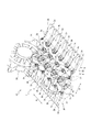
- FIG. 2 is a partial perspective view of the elastic crawler in FIG. 1 as a partial cross section, with a sprocket and an idler virtually shown from the inner peripheral surface side of the elastic crawler.
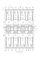
- FIG. 4 is a sectional view taken along line XX in FIG. 3.
- FIG. 4 is a YY sectional view of FIG. 3.
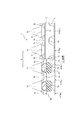
- FIG. 5 is a side view partially showing the elastic crawler of FIG. 1 in a ZZ cross section of FIG. 4.
- the crawler width direction is indicated by a symbol W
- the crawler circumferential direction is indicated by a symbol L
- the crawler thickness direction is indicated by D.
- the “crawler width direction” is the width direction of the elastic crawler 1, but is also synonymous with the width direction of the crawler body 2.
- the “crawler circumferential direction” is the circumferential direction of the elastic crawler 1, but is also synonymous with the circumferential direction of the crawler body 2.
- the “crawler thickness direction” is the thickness direction of the elastic crawler 1, but is also synonymous with the thickness direction of the crawler body 2.
- the elastic crawler 1 includes a crawler main body 2 formed endlessly by an elastic body, for example, as shown in FIGS.
- the crawler main body 2 is an annular member formed in a belt shape with the direction of the symbol W as the crawler width direction and the direction of the symbol L as the crawler circumferential direction.
- the crawler body 2 is made of rubber.
- the elastic crawler 1 includes a plurality of core bars 3 as indicated by broken lines in FIGS. 3 and 4.
- the cored bar 3 is embedded in the crawler main body 2 at intervals in the crawler circumferential direction, and extends in the crawler width direction.
- the central portion 3a of the cored bar 3 is located at the center in the crawler width direction.
- Each of the core bars 3 has a pair of wing portions 3b extending from the crawler width direction inner side to the crawler width direction outer side with the central portion 3a interposed therebetween.
- the central portion 3a of the cored bar 3 is provided with a pair of protrusions 3c that are arranged at intervals in the crawler width direction.
- the main cord layer 11 is disposed on the outer side in the crawler thickness direction (outer peripheral surface side of the crawler body 2) than the wing portion 3 b of the core metal 3.
- the main cord layer 11 is formed, for example, by arranging a plurality of steel cords that circulate the crawler body 2 in the crawler circumferential direction at intervals in the width direction.
- a rolling wheel rolling surface 2a is formed on the inner peripheral surface side of the crawler main body 2.
- a pair of roller rolling surfaces 2a are formed at intervals in the crawler width direction with the center in the crawler width direction interposed therebetween.
- Each of the roller rolling surfaces 2a constitutes a flat surface, and is, for example, an endless flat surface extending in the crawler circumferential direction as shown in FIGS. 2 and 4 to 7.
- a plurality of concave portions 2 b are provided on the inner peripheral surface side of the crawler body 2 between the wing portions 3 b of the cored bar 3 adjacent in the crawler circumferential direction. Is formed.
- each of the recesses 2b extends outward from the wheel raceway surface 2a in the crawler width direction.
- the concave portion 2 b is a portion where the wing portion 3 b of the core metal 3 in the crawler body 2 adjacent to the crawler circumferential direction as viewed in the crawler thickness direction (hereinafter referred to as “core metal”). It is also formed between 2c).
- core metal the core metal
- each of the recesses 2b extends in the crawler circumferential direction of the recess 2b toward the width direction edge 2e of the crawler body 2 (the recess 2b
- the crawler circumferential width) has an enlarged shape.
- the bottom surface 2 b 1 of the recess 2 b is directed toward the outer peripheral surface of the crawler body 2 as it goes toward the edge 2 e in the width direction of the crawler body 2 in the crawler thickness direction. It is inclined.
- an engagement portion described later is provided at the center in the width direction of the crawler main body 2 with an interval in the crawler peripheral direction.
- 2d is formed.
- 2 d of engaging parts are formed so that it may become in line with the recessed part 2b formed in the inner peripheral surface side of the crawler main body 2 in the crawler width direction. That is, the engaging portion 2d is formed at the same position as the concave portion 2b formed on the inner peripheral surface of the crawler body 2 in the crawler circumferential direction.
- the elastic crawler 1 includes a lug on the outer peripheral surface side of the crawler main body 2 that protrudes from the outer peripheral surface of the crawler main body 2 and surrounds a predetermined region R that overlaps with the cored bar 3 as viewed in the crawler thickness direction.
- the “go” includes not only the case where the entire region R is surrounded, but also the case where only one of the regions R is open. Specifically, a case where the region R is surrounded over half a circle or more, a case where the region R is surrounded over 2/3 times or more, and the like can be mentioned. In the present embodiment, for example, as shown in FIGS.
- the lugs are arranged on both sides of the crawler width direction of the crawler main body 2 with the center of the core metal 3 in the crawler width direction as viewed in the crawler thickness direction. And a center lug (lug) 5 that overlaps the center of the core metal 3 in the crawler width direction when viewed in the crawler thickness direction.
- the ground lug 4 and the central lug 5 are formed of rubber. Each of the ground lug 4 and the central lug 5 can be vulcanized and bonded to the outer peripheral surface of the crawler body 2, and can be formed integrally with the crawler body 2, for example. As shown in FIG. 3, in this embodiment, a pair of grounding lugs 4 are respectively arranged at intervals in the crawler width direction with the engaging portion 2d interposed therebetween. Moreover, in this embodiment, the some grounding lug 4 is arrange
- the ground lug 4 has a pair of width direction lug portions 4a adjacent to each other in the crawler circumferential direction.
- the pair of width direction lug portions 4a are arranged at intervals in the crawler circumferential direction.
- the outermost edge 2 a 1 in the crawler width direction of the roller contact surface 2 a formed on the inner peripheral surface side of the crawler body 2 is indicated by a two-dot chain line.
- the width direction lug portion 4a has a shape extending in the crawler width direction so as to shift in the crawler circumferential direction toward the outer side in the crawler width direction when viewed in the crawler thickness direction. is there.
- the inner end portion 4a 1 and the outer end portion 4a 2 of the widthwise lug portion 4a will be placed at a position shifted in the crawler circumferential direction.
- the wing part 3b of the cored bar 3 indicated by the broken line in FIG. 3 is arranged at a position overlapping the cored bar wing part embedded part 2c in the crawler thickness direction view.
- the position overlaps with the concave portion 2b formed on the inner peripheral surface of the crawler body 2 in the crawler thickness direction view. Is arranged.
- the grounding lug 4 has the connection lug part 4b which connects the two width direction lug parts 4a.
- the connecting lug portions 4b are formed between the width direction lug portions 4a adjacent to each other in the crawler circumferential direction, and connect the width direction lug portions 4a to each other.
- the connecting lug portion 4b is a portion including the outer end portion 4a 2 of the width direction lug portion 4a.
- the grounding lug 4 has the inner end portions 4 a 1 of the two widthwise lug portions 4 a at positions overlapping with the rolling wheel rolling surface 2 a and the core metal 3 in the crawler thickness direction view.
- a region R having an open portion A1 defined by a portion including the connecting lug portion 4b is formed, and at a position overlapping with the crawler circumferential direction of the two core bars 3 in a crawler thickness direction view, 2
- a notch A2 defined by a portion including the outer end portion 4a2 of the two widthwise lug portions 4a and a connecting lug portion 4b is formed.
- the ground contact surface 4f of the ground contact lug 4 is raised in the crawler thickness direction so that the two width direction lug portions 4a and the connecting lug portion 4b have the same height, so that the same surface is formed. It is configured.
- the ground lug 4 the opening portion A1 formed between the inner end 4a 1 of the pair of width direction lug portions 4a, from the gap G formed between the crawler circumferential direction of the ground lug 4
- the crawler circumferential direction gap at the same position in the width direction of the crawler main body 2 is configured as a narrow gap, but a wide gap may be used.
- the center lug 5 overlaps with the center of the core bar 3 in the crawler width direction as viewed in the crawler thickness direction, and among the ground lugs 4, the inner ends of the two widthwise lug portions 4a adjacent in the crawler circumferential direction.
- the parts 4a 1 are connected to each other.
- a position that overlaps with the core metal 3 by the crawler thickness direction when viewed, a portion including the inner end 4a 1 of the two widthwise lug portion 4a, a connecting lug portion 4b, a central lug 5 A region (predetermined region) R surrounded by is formed.
- the central lug 5 R is closer to the grounding surface 4f of the grounding lug 4 than the bottom surface 6 of R, and is raised to the same position as the grounding surface 4f of the grounding lug 4 or closer to the core 3 than the grounding surface 4f.
- the maximum raised surface 5a of the central lug 5 is formed at the position.
- the center lug 5 has the open part side inclined surface 5b which approaches the metal core 3 as it goes to the largest raised surface 5a and goes to the crawler width direction outer side.
- the region R is a region surrounded by the ground contact surface 4f of the ground lug 4 and the maximum raised surface 5a of the central lug 5 and having the deepest portion as the bottom surface 6.
- the maximum raised surface 5a is lower in height than the ground contact surface 4f of the ground lug 4, and thus only one of the regions R is opened in the crawler thickness direction view.
- the direction in which the opening portion A1 opens the region R is a direction along the crawler width direction, more specifically, a direction toward the center side in the crawler width direction (inside the crawler width direction) along the crawler width direction. It is.
- the opening A ⁇ b> 1 is formed on the cored bar 3 as viewed in the crawler thickness direction so as to open to the center side in the crawler width direction.
- the pair of ground lugs 4 arranged on both sides in the crawler width direction are mutually in the crawler circumferential direction with reference to the engaging portion 2 d formed on the crawler body 2. They are arranged at positions shifted by an interval between the two engaging portions 2d. Specifically, as shown in FIG.
- the right side of the drawing of the ground lug 4 the inner end portion 4a 1 crawler circumferential direction of one side of the inner end 4a 1 of the two widthwise lug portion 4a, the left side of the drawing of the ground lug 4, the inner end portion 4a 1 of the crawler circumferential direction of the other side of the inner end 4a 1 of the two widthwise lug portion 4a is, in the crawler width direction, the engaging portion of the crawler body 2 They are arranged in a line with 2d.
- the region R having the opening A1 are arranged so as to face each other.
- the gaps G formed between the grounding lugs 4 adjacent in the crawler circumferential direction are respectively connected to the maximum raised portion 5a of the central lug 5 and are formed on the core metal 3 toward the outer side in the crawler width direction. It has a gap-side inclined surface 5c that approaches. As shown in FIG. 5, the gap-side inclined surface 5 c is connected to the bottom surface 6. The clearance-side inclined surface 5c can be inclined at the same or different angle as the opening portion-side inclined surface 5b. As shown in FIG. 6, the bottom surface 6 of the gap G is connected to an inclined surface 7 that inclines toward the core metal 3 toward the edge 2 e in the width direction of the crawler body 2.
- the gap G is on the outer side in the crawler width direction, improves the bendability between the core bars 3 in the crawler circumferential direction, reduces running vibration, and snow that has been stepped on between the ground lugs 4 on the outer side in the crawler width direction. I can escape.
- a notch A ⁇ b> 2 is formed outside the crawler width of the ground lug 4.
- Grounding lug 4 the notch portion A2 formed between the outer end 4a 2 of the pair of width direction lug portion 4a is connected to the ground surface 4f of the ground lug 4, the widthwise end of the crawler body 2 from the ground surface 4f As it goes to the edge 2e, it is connected to the first inclined surface 8 inclined toward the core metal 3, the first inclined surface 8, the bottom surface 6 having the same height as the bottom surface 6 of the region R, and the bottom surface 6.
- the crawler body 2 is formed with a second inclined surface 9 that is inclined toward the core metal 3 toward the edge 2e in the width direction.
- the ground lug 4, the notch portion A2 formed between the outer end 4a 2 of the pair of width direction lug portion 4a is open in the crawler width direction outside.
- FIG. 2 shows a basic configuration of an elastic crawler device 10 according to an embodiment of the present invention, in which the elastic crawler 1 described above is a constituent element.
- the elastic crawler device 10 includes the above-described elastic crawler 1, and a driving wheel, a driven wheel, and a wheel on which the elastic crawler 1 is wound.
- reference numeral 20 denotes a sprocket or idler constituting the elastic crawler device 10.
- the sprocket 20 constitutes the driving wheel
- the idler 20 constitutes the driven wheel.
- the sprocket 20 has its teeth 21 engaged with the engaging portion 2 d to drive the elastic crawler 1, and the idler 20 is driven by the elastic crawler 1 driven by the sprocket 20.
- the engaging portion 2d is configured by a through-hole penetrating the crawler main body 2 in the thickness direction.
- the engaging portion 2d may be a recess without penetrating the crawler main body 2 in the thickness direction.
- Numeral 30 is a wheel constituting the elastic crawler device 10.
- the roller 30 rolls on the roller rolling surface 2 a formed on the inner peripheral surface of the crawler main body 2 in the elastic crawler 1.
- two rotating bodies 31 are connected via a shaft 32.
- the elastic crawler 1 includes an opening portion A1 that opens only one direction of the region R.
- the snow, mud, etc. clogged in the region R can be easily removed from the open portion A1, or the snow, mud, etc. clogged in the region R can be obtained by deforming the lug 4 from the open portion A1. Since the elastic crawler 1 can be used continuously, it is possible to suppress a decrease in packing property.
- the ground lug (the inner end 4a 1 And the connecting lug portion 4b) 4 are stepped and solidified in the region surrounded by the contact lug 4 to further improve the packing property.
- an opening A1 in part) 4 is formed on the center side of the crawler width direction of the ground lug 4 containing 4a 1 may be performed by moving the base point.
- the direction in which the opening A1 opens the region R is a direction along the crawler width direction. In this case, the lateral shift can be suppressed.
- the direction in which the opening A1 opens the region R is a direction toward the center in the crawler width direction along the crawler width direction.
- the escape to the outside of the crawler width direction of the portion that has been stepped on is suppressed, the escape of snow or the like is directed toward the center in the crawler width direction where the burden load from the aircraft is large, thereby reducing the packing property during traveling.
- a part of the lug surrounding the predetermined region R is the central lug 5 that overlaps the center of the core metal 3 in the crawler width direction when viewed in the crawler thickness direction.
- a part of the lug surrounding the predetermined region R is the central lug 5 that overlaps the central portion 3a of the core bar 3 in the crawler width direction.
- the region R is surrounded by the central lug 5 to which the most load is applied, such as a burden load from the airframe, thereby further improving the packing property. be able to.
- the lugs overlap and extend across a plurality of core bars 3 adjacent to each other in the crawler circumferential direction as viewed in the crawler thickness direction.
- the two width direction lug portions 4a of the grounding lug 4 respectively overlap and extend over a plurality of core bars 3 adjacent to each other in the crawler circumferential direction when viewed in the crawler thickness direction.
- an increase in the volume of the grounding lugs 4 per piece and, consequently, an increase in the area of the grounding surface 4f of the lugs 4 improves the transmission of driving force to snow or soft ground, etc.
- the occurrence of slips on low friction roads, etc. is suppressed, and further, wear and rubber chipping are suppressed. That is, it is possible to achieve both durability of the lug and running performance on snow or soft ground.
- the lug surrounding the region R is provided at one position opposed to the center in the crawler width direction, while the other position is provided. , A gap G is provided. In this case, running vibration can be suppressed while improving packing properties.
- the elastic crawler 1 includes two lugs that respectively surround the two regions R spaced apart in the crawler width direction, and each of the two lugs opens the region R. It is also preferable that the opening portions A1 face each other.
- the two ground lugs 4 are arranged at positions symmetrical with respect to the center line with a center line extending in the crawler circumferential direction passing through the center in the crawler width direction.
- the two opening portions A1 are arranged in a row at intervals in the crawler width direction, and these opening portions A1 are opened toward the same central lug 5.
- the edges 4e1, 4e2 of the region R in the crawler circumferential direction are respectively positioned between the crawler circumferential edges of the crawler circumferential edges 3e1, 3e2 of the core metal 3. ing.
- the grounding lug 4 is positioned so as to overlap with the highly rigid cored bar 3 in comparison with the elastic body in the crawler thickness direction, so that the snow can be stepped on with a stronger force and more packing property can be obtained. Improvements can be made.
- the elastic crawler 1 it is also preferable that at least one edge in the crawler circumferential direction of the region R coincides with at least one edge in the crawler circumferential direction of the core metal 3 in the crawler thickness direction view.
- the grounding lug 4 bends around the edges 3e1 and 3e2 in the crawler circumferential direction of the cored bar 3 as the elastic crawler 1 is wound around the sprocket or idler, so that the soil etc. clogged in the region R can be removed. Since it can be easily removed, it is possible to suppress a decrease in packing property due to continuous use of the elastic crawler 1.
- the lug preferably surrounds all directions of the region R.
- the maximum raised portion 5a of the central lug 5 the same height as the ground contact surface 4f of the ground lug 4
- all directions of the region R are surrounded by the ground lug 4 and the central lug 5, or
- the width direction lug portion 4a of each gap G and the notch portion A2 formed between the outer end portion 4a 2, the concave portion 2b formed on the inner peripheral surface of the crawler body 2 overlaps with the thickness direction of the crawler body 2, and the thickness of the crawler body 2 is locally reduced.
- the gap G and the notch A2 cooperate with the concave portion 2b formed on the inner peripheral surface of the crawler body 2 to make the elastic crawler 1 easy to bend sufficiently.
- the width direction of at least a portion of the crawler body 2 of the inner end portion 4a 1 inner end 4a 1 of the widthwise lug portion 4a, as shown in FIG. 6, the rolling wheel rotation plane 2a overlaps with the crawler body 2 in the thickness direction.
- each of the inner end 4a 1 in the width direction lug portion 4a which supports the rolling wheel rotation surface 2a.
- the elastic crawler 1 has an inner peripheral surface of the crawler main body 2 between the blade portions 3b of the cored bar 3 adjacent in the circumferential direction from the rolling wheel rolling surface 2a to the outer side in the width direction of the crawler main body 2.
- a plurality of recesses 2b are formed. Each of the recesses 2b is formed in a portion where there is no cored bar 3 extending in the width direction of the crawler body 2 with an interval in the circumferential direction.
- the wing portion of the core metal 3 from the inner end portion 4 a 1 that overlaps in the thickness direction of the crawler main body 2 between the roller contact surface 2 a and the core metal 3 adjacent in the circumferential direction.
- a plurality of widthwise lug portions 4 a extending in the width direction of the crawler main body 2 to the inner end portion 4 a 2 overlapping with the portion where 3 b is embedded in the thickness direction of the crawler main body 2 are formed.
- the elastic crawler 1 has a width of the crawler body 2 between the core bars 3 adjacent in the circumferential direction, in other words, in a portion where the core bar 3 extending in the width direction of the crawler body 2 does not exist.
- the inner end portion 4a 1 of the width direction lug portion 4a is disposed, while the outer end portions 4a 2 of the width direction lug portions 4a adjacent to each other in the circumferential direction on the outer side in the width direction of the crawler body 2.
- the gaps G are, among the gaps G formed between the grounding lugs 4 adjacent in the circumferential direction, the gaps G (in this embodiment, the notches formed by the connecting lug portions 4b) disposed on the outer side in the width direction of the crawler body 2. (Including part A2).
- the gap G formed by the width direction lug portion 4 a formed on the outer peripheral surface of the crawler main body 2 and the notch A ⁇ b> 2 are formed on the inner peripheral surface of the crawler main body 2. Since the crawler main body 2 (elastic crawler 1) is easily bent when the elastic crawler 1 is driven by disposing the crawler main body 2 in an overlapping position in the thickness direction, power loss during traveling is reduced, and fuel efficiency is improved. Can be achieved.
- the inner end portion 4 a 1 of the width direction lug portion 4 a is disposed at a position overlapping with the concave portion 2 b formed on the inner peripheral surface of the crawler body 2 in the thickness direction of the crawler body 2.
- the spring between the core bars 3 adjacent to each other in the circumferential direction becomes hard (in the portion where the inner end 4a 1 of the width direction lug portion 4a is disposed). Since the spring difference between the cored bar wing part embedded part 2c and the cored bar wing part embedded part 2c is reduced), the vibration during traveling is suppressed, so that the riding comfort is improved.
- the elastic crawler 1 it is possible to achieve both reduction of the bending resistance of the elastic crawler 1 and suppression of vibrations, and thus, it is possible to achieve both low fuel consumption and good riding comfort.
- the elastic crawler 1 if there is a connecting lug 4b formed between the widthwise lug portions 4a adjacent in the circumferential direction and connecting the widthwise lug portions 4a to each other, one piece is provided. Compared with the case where only the width direction lug portion 4a is used as a lug, the volume of the lug per piece increases, and as a result, the durability of the lug can be improved.
- the connecting lug portion 4b has a width adjacent to the circumferential direction at a position where the concave portion 2b formed on the inner peripheral surface of the crawler main body 2 and the crawler main body 2 overlap in the thickness direction.
- a cutout portion A2 formed by the direction lug portions 4a and the connecting lug portion 4b is provided.
- the notch A2 formed in the grounding lug 4 adjacent in the circumferential direction exists as a gap G formed between the widthwise lug portions 4a adjacent in the circumferential direction, and the inner peripheral surface of the crawler body 2
- the crawler body 2 (elastic crawler 1) can be easily bent while increasing the rigidity of the width direction lug portion 4a as the rigidity of the entire grounding lug 4 by overlapping with the concave portion 2b formed in the crawler body 2 in the thickness direction.
- the fuel consumption can be further reduced while improving the durability of the lug.
- the connecting lug portion 4 b is located at a position where the roller rolling surface 2 a and the cored bar 3 formed on the inner peripheral surface of the crawler body 2 overlap with the crawler body 2 in the thickness direction.
- the opening portion A1 formed by the width direction lug portions 4a adjacent to each other in the circumferential direction and the connecting lug portion 4b is formed.
- the elastic crawler device 10 according to the present embodiment, it is possible to achieve both low fuel consumption and good riding comfort.
- an elastic crawler and an elastic crawler device that can achieve both low fuel consumption and good riding comfort.
- the above description is only one embodiment of the present invention, and various modifications are possible according to the claims.
- the direction in which the opening A1 of the ground lug 4 opens the region R is at a position overlapping the cored bar 3 in the crawler thickness direction
- the direction toward the outside of the crawler width direction is of course along the crawler width direction.
- the direction extending along the crawler circumferential direction may also be used.
- the present invention can be used for an elastic crawler in which a lug protrudes from the outer peripheral surface of the crawler body.
Landscapes
- Engineering & Computer Science (AREA)
- Chemical & Material Sciences (AREA)
- Combustion & Propulsion (AREA)
- Transportation (AREA)
- Mechanical Engineering (AREA)
- Tires In General (AREA)
Abstract
Description
本発明に係る弾性クローラによれば、パッキング性が改善されることにより、雪又は軟弱な地面等への駆動力の伝達の向上を図ることができる。
この場合、弾性クローラを継続して使用することによるパッキング性の低下を抑制することができる。
この場合、横ずれの抑制を図ることができる。
この場合、雪又は軟弱な地面等への駆動力の伝達の更なる向上と横ずれの更なる抑制とを図ることができる。
この場合、雪又は軟弱な地面等への駆動力の伝達の更なる向上と横ずれの更なる抑制とを図ることができる。
この場合、パッキング性が改善されることにより、雪又は軟弱な地面等への駆動力の伝達の向上を図ることができる。
この場合、パッキング性を更に改善させることができる。
この場合、1個当たりのラグの体積が増えることで、ラグの耐久性を向上させることができる。
この場合、継続使用によるパッキング性の低下を抑制することができる。
Claims (9)
- 弾性体により無端状に形成されるクローラ本体と、
前記クローラ本体にクローラ周方向に間隔をおいて埋設され、クローラ幅方向に延在する芯金と、
前記クローラ本体の外周面から隆起し、クローラ厚み方向視で前記芯金と重複する所定の領域を囲繞するラグと、
を備える弾性クローラ。 - 前記ラグは、前記領域の一方向のみを開放する開放部を備える、請求項1に記載の弾性クローラ。
- 前記開放部が前記領域を開放する方向は、クローラ幅方向に沿う方向である、請求項2に記載の弾性クローラ。
- 前記開放部が前記領域を開放する方向は、クローラ幅方向に沿ってクローラ幅方向の中央側に向かう方向である、請求項3に記載の弾性クローラ。
- クローラ幅方向に間隔をおいた2つの前記領域をそれぞれ囲繞する2つのラグを備え、前記2つのラグのそれぞれが前記領域を開放するそれぞれの前記開放部は、互いに対向する、請求項2から請求項4の何れか1項に記載の弾性クローラ。
- 前記ラグは、前記領域の全方向を囲繞する、請求項1に記載の弾性クローラ。
- 前記所定の領域を囲繞する前記ラグの一部は、クローラ厚み方向視で前記芯金のクローラ幅方向の中央と重複する、中央ラグである、請求項1から請求項6の何れか1項に記載の弾性クローラ。
- 前記ラグは、クローラ厚み方向視でクローラ周方向に隣り合う複数の前記芯金に亘って重複して延在する、請求項1から請求項6の何れか1項に記載の弾性クローラ。
- 前記領域のクローラ周方向の少なくとも一方の端縁は、前記芯金のクローラ周方向の少なくとも一方の端縁とクローラ厚み方向視で一致する、請求項1から請求項7の何れか1項に記載の弾性クローラ。
Priority Applications (4)
| Application Number | Priority Date | Filing Date | Title |
|---|---|---|---|
| CN201680044752.5A CN107848588B (zh) | 2015-07-30 | 2016-07-28 | 弹性履带 |
| US15/741,767 US10435090B2 (en) | 2015-07-30 | 2016-07-28 | Elastic crawler |
| CA2994057A CA2994057C (en) | 2015-07-30 | 2016-07-28 | Elastic crawler |
| JP2017531022A JPWO2017017958A1 (ja) | 2015-07-30 | 2016-07-28 | 弾性クローラ |
Applications Claiming Priority (2)
| Application Number | Priority Date | Filing Date | Title |
|---|---|---|---|
| JP2015-151244 | 2015-07-30 | ||
| JP2015151244 | 2015-07-30 |
Publications (1)
| Publication Number | Publication Date |
|---|---|
| WO2017017958A1 true WO2017017958A1 (ja) | 2017-02-02 |
Family
ID=57884616
Family Applications (1)
| Application Number | Title | Priority Date | Filing Date |
|---|---|---|---|
| PCT/JP2016/003496 Ceased WO2017017958A1 (ja) | 2015-07-30 | 2016-07-28 | 弾性クローラ |
Country Status (5)
| Country | Link |
|---|---|
| US (1) | US10435090B2 (ja) |
| JP (1) | JPWO2017017958A1 (ja) |
| CN (1) | CN107848588B (ja) |
| CA (1) | CA2994057C (ja) |
| WO (1) | WO2017017958A1 (ja) |
Cited By (1)
| Publication number | Priority date | Publication date | Assignee | Title |
|---|---|---|---|---|
| WO2019097923A1 (ja) * | 2017-11-15 | 2019-05-23 | 株式会社ブリヂストン | ゴムクローラ |
Families Citing this family (1)
| Publication number | Priority date | Publication date | Assignee | Title |
|---|---|---|---|---|
| EP4601935A4 (en) * | 2022-10-12 | 2026-02-18 | Camso Inc | TRACK WITH IRREGULAR EDGES FOR VEHICLE TOWING |
Citations (3)
| Publication number | Priority date | Publication date | Assignee | Title |
|---|---|---|---|---|
| JPH0911937A (ja) * | 1995-06-28 | 1997-01-14 | Bridgestone Corp | ゴムクローラ |
| JP2012096638A (ja) * | 2010-11-01 | 2012-05-24 | Bridgestone Corp | 弾性クローラ |
| JP2012144143A (ja) * | 2011-01-12 | 2012-08-02 | Bridgestone Corp | ゴムクローラ |
Family Cites Families (12)
| Publication number | Priority date | Publication date | Assignee | Title |
|---|---|---|---|---|
| JPS5572469A (en) | 1979-07-23 | 1980-05-31 | Bridgestone Corp | Vibration proof elastic crawler |
| US6170925B1 (en) * | 1997-10-29 | 2001-01-09 | Bridgestone Corporation | Rubber crawler |
| JP4395208B2 (ja) | 1998-10-22 | 2010-01-06 | 株式会社ブリヂストン | ゴムクロ−ラの構造 |
| JP4272580B2 (ja) * | 2003-12-04 | 2009-06-03 | ゼニス産業株式会社 | 弾性クローラ |
| JP4069085B2 (ja) * | 2004-02-04 | 2008-03-26 | 住友ゴム工業株式会社 | ゴムクローラ |
| DE602005025012D1 (de) | 2004-12-02 | 2011-01-05 | Bridgestone Corp | Kernlose gummiraupenkette |
| DE602007010146D1 (de) * | 2006-07-06 | 2010-12-09 | Bridgestone Corp | Gummiraupenkette |
| JP5330748B2 (ja) | 2008-06-30 | 2013-10-30 | 株式会社ブリヂストン | 弾性クローラ |
| JP5264367B2 (ja) * | 2008-08-22 | 2013-08-14 | 株式会社ブリヂストン | ゴムクローラおよびクローラ式走行体 |
| JP5330775B2 (ja) | 2008-08-29 | 2013-10-30 | 株式会社ブリヂストン | 弾性クローラ |
| CN103118930B (zh) | 2010-09-21 | 2015-09-30 | 株式会社普利司通 | 弹性履带 |
| US10435091B2 (en) | 2015-07-30 | 2019-10-08 | Bridgestone Corporation | Elastic crawler and elastic crawler device |
-
2016
- 2016-07-28 US US15/741,767 patent/US10435090B2/en active Active
- 2016-07-28 WO PCT/JP2016/003496 patent/WO2017017958A1/ja not_active Ceased
- 2016-07-28 CA CA2994057A patent/CA2994057C/en active Active
- 2016-07-28 JP JP2017531022A patent/JPWO2017017958A1/ja active Pending
- 2016-07-28 CN CN201680044752.5A patent/CN107848588B/zh active Active
Patent Citations (3)
| Publication number | Priority date | Publication date | Assignee | Title |
|---|---|---|---|---|
| JPH0911937A (ja) * | 1995-06-28 | 1997-01-14 | Bridgestone Corp | ゴムクローラ |
| JP2012096638A (ja) * | 2010-11-01 | 2012-05-24 | Bridgestone Corp | 弾性クローラ |
| JP2012144143A (ja) * | 2011-01-12 | 2012-08-02 | Bridgestone Corp | ゴムクローラ |
Cited By (1)
| Publication number | Priority date | Publication date | Assignee | Title |
|---|---|---|---|---|
| WO2019097923A1 (ja) * | 2017-11-15 | 2019-05-23 | 株式会社ブリヂストン | ゴムクローラ |
Also Published As
| Publication number | Publication date |
|---|---|
| US10435090B2 (en) | 2019-10-08 |
| US20180201334A1 (en) | 2018-07-19 |
| CA2994057C (en) | 2019-10-29 |
| CN107848588A (zh) | 2018-03-27 |
| CA2994057A1 (en) | 2017-02-02 |
| CN107848588B (zh) | 2020-04-03 |
| JPWO2017017958A1 (ja) | 2018-05-24 |
Similar Documents
| Publication | Publication Date | Title |
|---|---|---|
| WO2017017957A1 (ja) | 弾性クローラおよび弾性クローラ装置 | |
| CN106232465B (zh) | 履带 | |
| JP5785952B2 (ja) | ゴムクローラ | |
| KR101772450B1 (ko) | 체인 및 체인용 가이드 플레이트 | |
| WO2017017958A1 (ja) | 弾性クローラ | |
| JP6934810B2 (ja) | ゴムクローラ | |
| JP6499010B2 (ja) | 弾性クローラおよび弾性クローラ装置 | |
| JP5213377B2 (ja) | ゴムクローラ | |
| US9919752B2 (en) | Elastic crawler | |
| JP5382762B2 (ja) | 弾性クローラ | |
| JP4722313B2 (ja) | 突起駆動型ゴムクローラ | |
| JP2724871B2 (ja) | 無限弾性軌道帯 | |
| CN109789902B (zh) | 弹性履带 | |
| JP2020172131A (ja) | クローラ | |
| TW201946818A (zh) | 彈性履帶 | |
| JP2015214305A (ja) | 弾性クローラおよびこれを備えたクローラ走行装置 | |
| JP7314617B2 (ja) | 弾性クローラ | |
| JP2018176830A (ja) | 弾性クローラ | |
| JP6479319B2 (ja) | ゴムクローラ | |
| JP6926867B2 (ja) | 弾性クローラ | |
| JPS5855945B2 (ja) | ゴムクロ−ラ | |
| WO2019097923A1 (ja) | ゴムクローラ | |
| JPH042583A (ja) | 弾性クローラ | |
| WO2018193918A1 (ja) | 弾性クローラ | |
| CN106414224A (zh) | 弹性履带以及具备该弹性履带的履带行驶装置 |
Legal Events
| Date | Code | Title | Description |
|---|---|---|---|
| 121 | Ep: the epo has been informed by wipo that ep was designated in this application |
Ref document number: 16830063 Country of ref document: EP Kind code of ref document: A1 |
|
| ENP | Entry into the national phase |
Ref document number: 2017531022 Country of ref document: JP Kind code of ref document: A |
|
| WWE | Wipo information: entry into national phase |
Ref document number: 15741767 Country of ref document: US |
|
| ENP | Entry into the national phase |
Ref document number: 2994057 Country of ref document: CA |
|
| NENP | Non-entry into the national phase |
Ref country code: DE |
|
| 122 | Ep: pct application non-entry in european phase |
Ref document number: 16830063 Country of ref document: EP Kind code of ref document: A1 |